EP4098447A1 - Machine d'usinage dotée d'un dispositif de séchage et procédé permettant de faire fonctionner un dispositif de séchage - Google Patents
Machine d'usinage dotée d'un dispositif de séchage et procédé permettant de faire fonctionner un dispositif de séchage Download PDFInfo
- Publication number
- EP4098447A1 EP4098447A1 EP22185084.5A EP22185084A EP4098447A1 EP 4098447 A1 EP4098447 A1 EP 4098447A1 EP 22185084 A EP22185084 A EP 22185084A EP 4098447 A1 EP4098447 A1 EP 4098447A1
- Authority
- EP
- European Patent Office
- Prior art keywords
- air
- radiation source
- housing
- blown
- radiator
- Prior art date
- Legal status (The legal status is an assumption and is not a legal conclusion. Google has not performed a legal analysis and makes no representation as to the accuracy of the status listed.)
- Granted
Links
- 238000012545 processing Methods 0.000 title claims abstract description 47
- 238000001035 drying Methods 0.000 title claims abstract description 39
- 238000000034 method Methods 0.000 title claims description 14
- 239000003570 air Substances 0.000 claims abstract description 248
- 230000005855 radiation Effects 0.000 claims abstract description 53
- 239000012080 ambient air Substances 0.000 claims abstract description 38
- 230000001105 regulatory effect Effects 0.000 claims abstract description 5
- 238000001816 cooling Methods 0.000 claims description 73
- 238000007639 printing Methods 0.000 claims description 56
- 230000000694 effects Effects 0.000 claims description 9
- 239000000463 material Substances 0.000 description 37
- 239000011521 glass Substances 0.000 description 15
- 239000000758 substrate Substances 0.000 description 15
- 239000000976 ink Substances 0.000 description 6
- QSHDDOUJBYECFT-UHFFFAOYSA-N mercury Chemical compound [Hg] QSHDDOUJBYECFT-UHFFFAOYSA-N 0.000 description 6
- 239000002966 varnish Substances 0.000 description 4
- CBENFWSGALASAD-UHFFFAOYSA-N Ozone Chemical compound [O-][O+]=O CBENFWSGALASAD-UHFFFAOYSA-N 0.000 description 3
- 229910052751 metal Inorganic materials 0.000 description 3
- 239000002184 metal Substances 0.000 description 3
- 238000007664 blowing Methods 0.000 description 2
- 239000011248 coating agent Substances 0.000 description 2
- 238000000576 coating method Methods 0.000 description 2
- 230000001419 dependent effect Effects 0.000 description 2
- 238000003780 insertion Methods 0.000 description 2
- 230000037431 insertion Effects 0.000 description 2
- 239000004922 lacquer Substances 0.000 description 2
- 238000009281 ultraviolet germicidal irradiation Methods 0.000 description 2
- 230000006978 adaptation Effects 0.000 description 1
- 229910052782 aluminium Inorganic materials 0.000 description 1
- XAGFODPZIPBFFR-UHFFFAOYSA-N aluminium Chemical compound [Al] XAGFODPZIPBFFR-UHFFFAOYSA-N 0.000 description 1
- 230000001174 ascending effect Effects 0.000 description 1
- 238000005452 bending Methods 0.000 description 1
- 238000009529 body temperature measurement Methods 0.000 description 1
- 238000010276 construction Methods 0.000 description 1
- 238000013461 design Methods 0.000 description 1
- 238000011161 development Methods 0.000 description 1
- 238000006073 displacement reaction Methods 0.000 description 1
- 230000005611 electricity Effects 0.000 description 1
- 238000000605 extraction Methods 0.000 description 1
- 238000001125 extrusion Methods 0.000 description 1
- 230000017525 heat dissipation Effects 0.000 description 1
- 238000009434 installation Methods 0.000 description 1
- 238000011835 investigation Methods 0.000 description 1
- 230000007257 malfunction Effects 0.000 description 1
- 230000001681 protective effect Effects 0.000 description 1
- 230000009466 transformation Effects 0.000 description 1
Images


Classifications
-
- B—PERFORMING OPERATIONS; TRANSPORTING
- B41—PRINTING; LINING MACHINES; TYPEWRITERS; STAMPS
- B41F—PRINTING MACHINES OR PRESSES
- B41F23/00—Devices for treating the surfaces of sheets, webs, or other articles in connection with printing
- B41F23/04—Devices for treating the surfaces of sheets, webs, or other articles in connection with printing by heat drying, by cooling, by applying powders
- B41F23/044—Drying sheets, e.g. between two printing stations
- B41F23/045—Drying sheets, e.g. between two printing stations by radiation
- B41F23/0453—Drying sheets, e.g. between two printing stations by radiation by ultraviolet dryers
-
- B—PERFORMING OPERATIONS; TRANSPORTING
- B41—PRINTING; LINING MACHINES; TYPEWRITERS; STAMPS
- B41F—PRINTING MACHINES OR PRESSES
- B41F23/00—Devices for treating the surfaces of sheets, webs, or other articles in connection with printing
- B41F23/04—Devices for treating the surfaces of sheets, webs, or other articles in connection with printing by heat drying, by cooling, by applying powders
- B41F23/0403—Drying webs
- B41F23/0406—Drying webs by radiation
- B41F23/0409—Ultraviolet dryers
-
- B—PERFORMING OPERATIONS; TRANSPORTING
- B41—PRINTING; LINING MACHINES; TYPEWRITERS; STAMPS
- B41F—PRINTING MACHINES OR PRESSES
- B41F23/00—Devices for treating the surfaces of sheets, webs, or other articles in connection with printing
- B41F23/04—Devices for treating the surfaces of sheets, webs, or other articles in connection with printing by heat drying, by cooling, by applying powders
- B41F23/0483—Drying combined with cooling
Definitions
- the invention relates to a processing machine with a drying device, in particular a printing material or sheet processing or substrate processing machine, especially a printing press, and a method for operating a drying device in a processing machine.
- UV emitters installed in a UV module on printing material processing machines are cooled during operation. Cooling of a UV radiator is also necessary at higher outputs so that it does not reach the transformation temperature of the glass tube and thus sags or even puffs up.
- Exhaust air cooling systems for cooling UV radiators are known. Ambient air flows past the UV emitter through an air inlet opening in the housing, with the air inlet opening also being the radiation outlet opening.
- the disadvantage is that the UV radiator, as a result of the structural design, is primarily cooled on the top.
- the underside is generally significantly hotter, as there is insufficient convection. The heat dissipation on the underside takes place in addition to heat radiation through heat conduction from the glass tube to the well-cooled top.
- an irradiation device wherein the radiation source in the irradiation device is arranged to be rotatable about its longitudinal axis in connection with an intake air cooling system.
- the disadvantage of this solution is that it works with an intake air cooling system and has moving parts that are prone to failure, making it complex and uneconomical.
- a UV irradiation device in which a first flow of cooling air is sucked into the housing on the sides via air inlet openings in the outer wall in order to cool the bulkhead system from the outside.
- the cooling air is routed along the housing wall into a central suction duct and from there, via a collector, to a fan that promotes the entire flow of cooling air for the UV irradiation device.
- a second flow of cooling air is collected in the area of the radiation source by a long-necked suction duct and fed into the collector via a throttle.
- a disadvantage of this solution is that this exhaust air cooling does not adequately cool the underside of the radiation source.
- the DE 102 47 464 A1 shows a dryer device with an infrared radiator, with a main dryer assembly being arranged downstream of an after-dryer assembly.
- the dryer device is sealed off from cold ambient air.
- an ultraviolet curing apparatus using a UV ray tube is known.
- the distance between the reflectors and the radiator is adjusted via the length of the radiator.
- an air pipe is used, which directs cooling air directly onto the radiator.
- the cooling air discharged from the air duct is configured to increase in amount as it is farther from an exhaust side.
- FIG. 12 shows a cooling apparatus for an ultraviolet lamp using blown air to cool substrate in order to prevent in advance damage that may be caused by malfunction of the shutter members of the housing.
- the object of the invention is to create an alternative processing machine with a drying device or an alternative method for operating a drying device in a processing machine.
- the cooling on preferably high-performance dryers in processing machines, such as substrate or printing material processing machines should be improved.
- the cooling of a UV radiator should also be further improved on the underside.
- the object is achieved by a device having the features of the independent device claim and a method having the features of independent method claim solved.
- Advantageous configurations result from the dependent claims, the description and the drawings.
- the invention has the advantage that an alternative processing machine with a drying device or an alternative method for operating a drying device in a processing machine is created.
- the cooling on preferably powerful dryers in processing machines, such as substrate or printing material processing machines, in particular printing presses or sheet processing machines, is improved.
- the cooling of a UV radiator on the underside is also particularly preferably further improved.
- the drying device is preferably used in a sheet-processing or substrate-processing machine, especially a printing press, or such a machine is equipped with one or more such drying devices.
- the drying device can preferably also be used optionally as an intermediate dryer or as a final dryer, for example in a delivery.
- a tabular substrate for example sheet metal, can be processed as the substrate.
- material in rolls or sheets can also be processed, in particular printed or painted.
- a particular advantage of exhaust air cooling is that ozone generated by UV radiation is simultaneously extracted from the drying device, for example a UV module.
- ozone is harmful to human health, on the other hand, ozone absorbs UV radiation and thus reduces the curing effect of the drying device, in particular the UV module.
- a blown air system results in improved air flow with the favored exhaust air cooling.
- Ambient air is preferred, in particular that which is outside of the drying device or that is in contact with a printing material Ambient air, guided in a targeted manner by additional directed air and/or blown air in such a way that both the ambient air and the additional air or blown air are optimally guided as cooling air around the radiation source before the common cooling air is removed as exhaust air through one or more air outlet openings, in particular sucked off , becomes.
- the radiation source can be cooled indirectly and/or directly on the underside by air streams introduced on one side or preferably on both sides, for example blown air streams or blasted air jets, with the additional air, for example blown air, being introduced or blown in in particular outside the radiation area of a UV module .
- air is preferably introduced or blown in on both sides, it can meet, for example, in the middle below the UV module or below the radiation source.
- the radiation source in particular a UV emitter, can also be partly blown directly on from below.
- blown air is guided parallel to or in the plane of the air inlet opening of the housing, so that the blowing device is not in the beam path of the radiation from the radiation source.
- the blown air is thus preferably generated at least approximately parallel to the web of processing material or a web of printing material.
- cooling air in the drying device in particular in the UV module, in an improved or optimized manner to the underside of the radiation source and the underside is therefore better cooled.
- the cooling is advantageously more turbulent and, surprisingly, the upper side of the radiation source is also cooled better, which has been proven by investigations, specifically using temperature measurements.
- a drying device for example the UV module, or the radiation source introduced or blown.
- This can be done by air guiding elements, such as metal sheets, and/or blown air openings, in particular nozzles.
- the air introduced or blown in on both sides can be either a partial mass or at least approximately all of the cooling air discharged in the UV module.
- the air volume flow of the air that is additionally introduced or blown in by the blast air system can preferably be between 20% and 50% of the total cooling air volume flow. Accordingly, the proportion of inflowing ambient air can be between 80% and 50%. In particular, a ratio of at least approximately 1/3 of air that is additionally introduced or blown in by the blast air system and of at least approximately 2/3 of inflowing ambient air is sought.
- the radiation sources in particular UV emitters, can thus be operated particularly advantageously with even higher power or the air mass flow can be reduced with the same cooling. Another advantage is that a bending or blowing up of a UV radiator can be avoided more reliably.
- the blown air system is designed as an add-on module or additional module, which can be designed to be detachably or non-detachably connectable to a UV module of a dryer.
- the blown air system can be designed to be placed on any UV module of a dryer.
- the add-on module comprises, in particular, separate air guiding elements or air guiding channels, which are provided for influencing or adjusting the ambient air volume flow flowing around the radiation source.
- An add-on module or additional module can easily be used to retrofit dryers.
- a disc spaced apart from the housing of the UV module could also be provided in the beam path of the radiation source, as long as a sufficient air volume flow flowing into at least one air inlet opening is ensured.
- Substrates or printing materials are conveyed through the machine in processing machines such as printing material processing machines, in particular printing presses or sheet-fed processing machines, for example sheet-fed printing machines, in particular sheet-fed offset rotary printing machines, preferably in aggregate and in-line construction.
- processing machines such as printing material processing machines, in particular printing presses or sheet-fed processing machines, for example sheet-fed printing machines, in particular sheet-fed offset rotary printing machines, preferably in aggregate and in-line construction.
- sheet processing machines for example, sheets of printing material are gripped by cylinders or drums at the front edge and conveyed or transported through the machine while the cylinders are rotating. Between The sheets of printing material are transferred to cylinders when the gripper closes.
- the substrates run through various printing units on the conveying path, in which they are each printed with a printing color corresponding to the desired motif.
- Each of the printing units can, for example, include a plate cylinder, which is inked by an inking unit with the printing ink used.
- This inked plate cylinder transfers the printing ink appropriate to the motif onto a rubber cylinder provided with a rubber blanket, which forms a printing gap with a printing cylinder of a sheet-fed printing press that conveys the substrate sheet.
- the corresponding motif is transferred from the inked rubber blanket of the rubber cylinder to the substrate sheet.
- the finished printed sheets of printing material can be laid out in a delivery of a sheet-fed printing press to form a delivery stack.
- the last printing unit can also be followed, for example, by one or more varnishing units which provide the printed sheets of printing material with a protective varnish or glossy varnish.
- UV inks are preferably used in the printing units and UV varnishes in the coating units.
- a printing machine can contain a turning device for double-sided perfecting printing. Alternatively, however, other printing methods, for example with variable motifs, can also be used.
- a drying device or an intermediate dryer in the machine is designed in particular as a UV drying device and includes, for example, one or more UV modules 1.
- the 1 shows, for example, part of a delivery of a sheet-fed printing press with a drying device arranged above a sheet conveying path, in particular with a dryer, which has a plurality of UV modules 1.
- the drying device can also have a hot-air dryer, among other things.
- the display not shown, are arranged on chains and are driven by these endlessly revolving gripper carriage 5 provided which the processed sheet 4 at the front edge from take over the last cylinder and promote it on the sheet conveyor path to the delivery pile.
- the UV modules 1 are arranged at a specified distance from the sheet conveying path, so that the circulating gripper carriage 5 can move unhindered.
- the sheets 4 can be guided over sheet guide plates 6, with an air cushion being able to be formed between the sheet 4 and the sheet guide plates 6.
- the UV modules 1 can also be arranged in the ascending branch of the circulating chains and/or in a delivery extension.
- a drying device can also be arranged below the sheet conveying path.
- the UV modules 1 each have UV emitters 2 whose UV radiation is directed onto the surface of the sheet 4 directly or via reflectors 3 .
- the treated sheet surface in particular the printed UV ink and/or the applied UV varnish, is dried or cured by this UV radiation acting on the sheet 4 .
- Mercury vapor lamps are preferably used as radiation sources in the UV modules 1 .
- emitters with other wavelengths such. B. infrared dryer, are used.
- slide-in shafts into which the UV modules 1 can be inserted can be provided in the machine or delivery.
- the UV modules 1 can be fixed in these slots, making it possible to replace the UV modules 1, e.g. B. wear of the UV lamp 2 is guaranteed.
- the UV modules 1 work in particular with exhaust air cooling.
- the 2 shows a drying device, in particular a UV module 1, on a sheet-guiding cylinder 7 of a sheet-processing machine, for example the sheet-fed printing press described above.
- the UV module 1 is assigned to the sheet guiding cylinder 7 of a work, in particular as an intermediate dryer.
- the sheet guiding cylinder 7 preferably contains gripper systems, which are used here in particular as Clamping grippers are formed with gripper fingers and gripper pads. The gripper fingers fix the leading edge of the sheet by a gripping movement on the gripper pads, so that the sheet 4 is fixed for transport on the lateral surface of the sheet guiding cylinder 7 rotating in the direction shown.
- the UV module 1 can be arranged in a printing, coating, drying or processing unit etc. of the machine.
- the UV module 1 can be used as an intermediate dryer, in particular between printing units of the machine for drying one or more inks or lacquers, in particular UV inks or UV lacquers.
- the intermediate dryer can also be plugged into an insertion shaft of the machine and can therefore be designed to be exchangeable.
- the UV modules 1 can be interchangeable between the slide-in shafts of the intermediate dryer and the delivery.
- the UV module 1 designed as an intermediate dryer works in particular with exhaust air cooling.
- the 3 shows a UV module 1, which accommodates a UV radiation source, in particular a gas discharge tube filled with mercury vapor, extending longitudinally transversely to the conveying direction of the processing material, for example the printing material or sheet 4.
- the UV module 1 can, for example, be assigned to an insertion shaft of the machine, which preferably also has electrical or pneumatic connections for supply. The corresponding electrical or pneumatic connections can be provided in the slide-in slot, for example.
- a blown air system 13 is assigned to the UV module 1, which extends in particular over the maximum material width to be processed by the machine, for example the width of the printing material.
- the blast air system 13 has an overpressure supply, which includes, for example, an overpressure connection or preferably an overpressure generator.
- the overpressure generators can be embodied as fans, in particular as axial fans 14, preferably distributed over the width of the printing material.
- Fans, in particular axial fans 14, can be supplied with electricity separately or together with the UV module 1.
- the UV module 1 On the dem On the side facing the processing material or printing material, the UV module 1 has an air inlet opening 10 for the ambient air, ie the air that comes into contact with the substrate or printing material or is in the beam path of the UV module 1 .
- the air inlet opening 10 is here in particular at the same time the radiation outlet opening of the UV radiator 2 of the UV module 1.
- the UV module 1 can in particular have a housing profile 8 in which an exhaust air duct 12 is preferably arranged.
- an extrusion profile of the UV module 1 can typically be made of aluminum.
- the reflectors 3 installed in known shutters 9 reflect the radiation of the UV radiator 2 to the substrate or printing material.
- the shutters 9 are preferably provided in the housing profile 8 along the UV radiator 2 .
- the shutters 9 are preferably designed to be movable and/or liquid-cooled.
- the shutters 9 each have, for example, an axis of rotation which is arranged parallel to the extension of the UV radiator 2 and about which the shutters 9 can move.
- the air inlet opening 10 of the housing profile 8 is in particular closed. During operation, the shutters 9 are accordingly held in a position that releases the air inlet opening 10 .
- the cooling air then flows between the shutters 9 in the exhaust air duct 12 of the housing profile 8.
- the exhaust air duct 12 is preferably connected on one side to a suction air source that can be controlled or regulated, for example, and which sucks the exhaust air into the exhaust air duct 12 .
- the exhaust air duct 12 preferably extends over the entire length of the UV emitter 2 so that the air heated by the UV emitter 2 can be sucked off into the exhaust air duct 12 through distributed openings.
- the exhaust air duct 12, which extends along the radiation source, in particular the UV radiator 2 is connected to the space surrounding the UV radiator 2 via elongated holes spaced apart from one another.
- the elongated holes are preferably dimensioned in such a way that they differ from one another in terms of their opening areas.
- the opening areas of the elongated holes between the ends of an elongated UV emitter 2 are dimensioned smaller than the elongated holes provided at the respective ends of the UV emitter 2 .
- the opening areas of the elongated holes between the ends of the elongated UV radiator 2 are very preferably dimensioned to be continuously smaller, in particular without local maxima towards the suction air source of the exhaust air duct 12 .
- the opening areas of the elongated holes assigned to the ends of the elongated UV emitter 2 are dimensioned differently from one another, with the opening area of at least one elongated hole of the end of the UV emitter 2 facing the suction air source of the exhaust air duct 12 preferably being dimensioned smaller than an opening area of at least one elongated hole the end of the UV radiator 2 facing away from the suction air source of the exhaust air duct 12.
- the slots facing the respective ends of the UV radiator 2 can also include two, three or four slots.
- the air flows resulting from operation with activated exhaust air cooling and deactivated blast air system 13 are shown here in principle or schematically.
- cooling takes place primarily on the upper side of the UV radiator 2, while the lower side facing the processing material is cooled less than the upper side.
- the operating mode for example, a warm-up can take place.
- This operating mode can also be provided during operation, for example when the UV module 1 is operated at low power, especially when the glass tube temperature is low, for example with a lamp power of less than 140 to 120 W/cm.
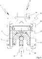
- the figure 5 shows the cross section of UV module 1 with activated blast air system 13, here in particular the attachable blast air system 13.
- One or more fans here in particular axial fans 14, generate an air flow in air ducts 15 to the air inlet opening 10 facing the processing material or printing substrate.
- a blast air jet 17 is preferably generated on both sides of the air inlet opening 10 by blast air openings 16 .
- the blown air jets 17 can each be formed by individual blown air openings 16 or by continuous slot nozzles, which extend, for example, over the length of the radiation source, in particular at least between electrodes 19 of a UV emitter 2 .
- the gap formed by the blast air openings 16 can also be designed to be adjustable, so that, for example, a setting for performance classes and/or an adaptation to installation spaces or machines can be carried out.
- a gap of 1 mm to 10 mm, particularly preferably of 2 mm to 6 mm and very particularly preferably of at least approximately 4 mm, opened by the blown air openings 16, is preferably set.
- the blown air jets 17 generated by the blown air system 13 are in particular aligned towards one another in one plane in such a way that they influence, in particular narrow or constrict, the ambient air flow 11 flowing into the housing profile 8 .
- the blown air jets 17 are preferably guided towards one another in one plane in such a way that they would preferably meet in the middle of the air inlet opening 10 , for example exactly below the UV radiator 2 .
- the ambient air flow 11 is preferably influenced in such a way that the ambient air flow 11 cools the underside of the UV radiator 2 facing the processing material or printing material with increased intensity.
- the blast air system 13 generates in particular a cross flow to the flow of ambient air 11 .
- the 6 shows a UV module 1 with an alternative blown air system 13 that can also be attached, for example.
- the blown air system 13 also has one or more fans, in particular axial fans 14, which generate an air flow flowing in air ducts 15 to the air inlet opening 10 facing the substrate or printing material.
- the blast air system 13 has blast air openings 16 here, which do not blow directly onto the UV radiator 2 but rather constrict or constrict the inflowing ambient air flow 11 below the UV radiator 2 or before it reaches the UV radiator 2 . Since the air ducts 15 or blown air openings 16 can sit at least partially in the beam path of the UV radiator 2, they can also be made of a radiation-transmissive material.
- the 7 shows a UV module 1 with a longitudinally extending UV radiator 2 and associated alternative blast air system 13.
- the blast air system 13 has at least one compressed air connection 18, air ducts 15 and one or more blast air openings 16.
- each air duct 15 extending across the format width transversely to the conveying direction of the processing material is assigned at least one compressed air connection 18, which applies a higher pressure than the ambient pressure to the respective air duct 15.
- the overpressure can develop over the format width and exit via the blast air openings 16 as a blast air jet 17.
- the 8 shows the cross section of the UV module 1 according to section AA of the previous figure with the alternative blast air system 13.
- the compressed air supplied via the respective compressed air connection 18 is distributed over the respective air duct 15 and exits via the blast air openings 16 in the area of the air inlet opening 10 of the UV -module 1 off.
- the blast air jets 17 can each be generated by individual blast air openings 16 or by continuous slot nozzles, which extend, for example, over the width of the processing material or printing material.
- the Blown air jets 17 are in particular aligned towards one another in a plane in such a way that they influence, in particular narrow or constrict, the ambient air flow 11 flowing into the housing profile 8 .
- the influencing of the ambient air flow 11 preferably takes place analogously in such a way that the ambient air flow 11 cools the underside of the UV radiator 2 facing the processing material or printing material with increased intensity.
- the 9 shows an elongate UV emitter 2 designed as a mercury vapor lamp, for example, with a cooling system or blast air system 13 acting exclusively between electrodes 19.
- the UV emitter 2 designed as a medium-pressure mercury vapor lamp, for example, has the two ends arranged in a glass body 20 that are contacted or connected via a pin 21 .
- the electrodes 19 can be controlled, for example, by an integrated or external pilot control device.
- Each of the two spaced apart electrodes 19 lies at least partially in a plane E1, E2 which the elongated UV radiator 2, for example the mercury vapor lamp, intersects as an idealized common normal (as an orthogonal vector).
- the planes E1, E2 are to be understood as idealized parallel planes spaced apart from one another in space, with the surfaces of the electrodes 19 at least touching the planes E1, E2.
- a cooling area B of the cooling system or blast air system 13 is located in particular exclusively between the mutually facing electrode surfaces spanning the planes E1, E2.
- the cooling area B of the cooling system or blast air system 13 with a maximum cooling capacity is preferably formed or limited here by the two levels E1, E2.
- the cooling system or blown air system 13 of the radiation source has a maximum cooling capacity here exclusively in a cooling area B between the planes E1, E2 formed by the electrodes 19.
- a constant cooling capacity is preferably generated over the entire cooling area B, with the Cooling area B particularly preferably extends completely between the facing surfaces of the electrodes 19.
- the maximum cooling capacity in cooling area B can be controlled or regulated according to the desired requirement in terms of intensity or effect. Adjacent to the cooling area B, in particular outside of the planes E1, E2, the cooling capacity of the cooling system or the blown air system 13 is reduced compared to the maximum cooling capacity or is preferably zero.
- the glass body 20 has a larger diameter compared to the edge areas.
- the glass body 20 enclosing the electrodes 19 tapers, with the tapered ends of the glass body 20 carrying in particular the pins 21 for making electrical contact with the electrodes 19.
- the electrodes 19 are therefore preferably physically largely outside the cooling area B of the cooling system or blast air system 13.
- This embodiment is particularly preferably used in medium-format machines, such as sheet-fed printing presses.
- Medium format machines for example, can process processing material with a width of at least approximately 1 m.
- the 10 shows an alternative elongated UV radiator 2, which is particularly suitable for large-format machines.
- Large-format machines such as sheet-fed presses, can, for example, process processing material with a width of more than 1 m, for example approximately 1.4 m or 1.6 m or even more.
- the UV radiator 2 is characterized in that the planes E1, E2 intersect the tapering areas of the glass body 20. The maximum diameter of the glass body 20 is thus only reached within the cooling area B delimited by the planes E1, E2. In particular when the shutters 9 are closed, this prevents the ambient air then flowing in from the side from cooling the electrodes 19 too much.
- the 11 shows an alternative embodiment of a UV radiator 2.
- the glass body 20 only tapers outside of the planes E1, E2.
- the planes E1, E2 thus intersect the glass body 20 in the area of the maximum diameter.
- the planes E1, E2 delimiting the cooling area B of the cooling system or blast air system 13 are also spanned here by the mutually facing surfaces of the electrodes 19 of the UV radiator 2.
- the radiation source in particular a UV radiator 2
- air is preferably blown in on both sides, in particular outside the radiation area of the UV module 1.
- This air preferably meets in the middle below the UV module 1 , in particular approximately in the middle of the UV radiator 2 .
- the underside of the UV radiator 2 is thus greatly cooled. Furthermore, the cooling becomes more turbulent overall and the upper side of the UV radiator 2 is also better cooled.
- the additional air is preferably introduced or blown in exclusively between electrodes 19 of the UV radiator 2 or over the length of the UV module 1 . This can be done using metal sheets and/or blast air nozzles.
- the air that is preferably introduced or blown in on both sides can be either a partial mass or also at least approximately all of the cooling air acting in the UV module 1 .
- a proportion of 80% to 50% of the cooling air is formed by the inflowing ambient air flow 11 and a proportion of 20% to 50% of the cooling air is formed by the air introduced by the blast air system 13 .
- a proportion of 1/3 of the air or blown air 17 additionally introduced by the blown air system 13 and a proportion of 2/3 of the inflowing ambient air flow 11 is aimed for.
- the UV radiator 2 can be operated with a power of between approximately 80 W/cm and approximately 200 W/cm.
- the blown air system 13 can be activated or switched on depending on the power.
- the blown air system 13 can only be activated at a medium output, for example at approximately 120 to 140 W/cm.
- the blown air system 13 can be completely deactivated below a radiator output of, for example, 120 to 140 W/cm.
- the blown air system 13 can just be activated, for example.
- the effect of the blast air system 13 can preferably be increased with the radiator power.
- the effect of the blast air system 13 can just start at a radiator output of 120 to 140 W/cm and can be increased up to a maximum radiator output of 200 W/cm, preferably linearly or depending on the function, so that the effect of the blast air system 13 with a radiator output of 200 W /cm is 100%.
- the blown air can be adjusted in particular according to a characteristic map, which can have local maxima and/or minima, for example.
- the blown air can be set as a function of a curve defined, for example, between 120 W/cm and 200 W/cm.
- a function for operating the blast air system 13 as a function of the radiator power can be predetermined and/or modified, in particular as a function of the machine.
- the effect of the blown air system 13 can also be set individually and/or also be controlled or regulated, for example, according to the radiator output.
- the current radiator power can be known to a control device, in particular the machine control, or can be determined by a sensor system.
Landscapes
- Engineering & Computer Science (AREA)
- Mechanical Engineering (AREA)
- Health & Medical Sciences (AREA)
- General Health & Medical Sciences (AREA)
- Toxicology (AREA)
- Supply, Installation And Extraction Of Printed Sheets Or Plates (AREA)
- Drying Of Solid Materials (AREA)
- Washing And Drying Of Tableware (AREA)
- Processing And Handling Of Plastics And Other Materials For Molding In General (AREA)
- Treatment Of Fiber Materials (AREA)
Applications Claiming Priority (3)
| Application Number | Priority Date | Filing Date | Title |
|---|---|---|---|
| DE102018206154.8A DE102018206154B4 (de) | 2018-04-20 | 2018-04-20 | Trocknungsvorrichtung für eine bedruckstoffverarbeitende Maschine und Verfahren zum Betreiben einer Trocknungsvorrichtung |
| PCT/EP2019/059858 WO2019201960A1 (fr) | 2018-04-20 | 2019-04-16 | Machine de traitement équipée d'un sécheur à rayons et procédé de fonctionnement de ce sécheur |
| EP19719223.0A EP3781404B1 (fr) | 2018-04-20 | 2019-04-16 | Machine de traitement dotée d'un séchoir à rayonnement et procédé destiné au fonctionnement |
Related Parent Applications (2)
| Application Number | Title | Priority Date | Filing Date |
|---|---|---|---|
| EP19719223.0A Division EP3781404B1 (fr) | 2018-04-20 | 2019-04-16 | Machine de traitement dotée d'un séchoir à rayonnement et procédé destiné au fonctionnement |
| EP19719223.0A Division-Into EP3781404B1 (fr) | 2018-04-20 | 2019-04-16 | Machine de traitement dotée d'un séchoir à rayonnement et procédé destiné au fonctionnement |
Publications (2)
| Publication Number | Publication Date |
|---|---|
| EP4098447A1 true EP4098447A1 (fr) | 2022-12-07 |
| EP4098447B1 EP4098447B1 (fr) | 2023-06-28 |
Family
ID=66251764
Family Applications (2)
| Application Number | Title | Priority Date | Filing Date |
|---|---|---|---|
| EP19719223.0A Active EP3781404B1 (fr) | 2018-04-20 | 2019-04-16 | Machine de traitement dotée d'un séchoir à rayonnement et procédé destiné au fonctionnement |
| EP22185084.5A Active EP4098447B1 (fr) | 2018-04-20 | 2019-04-16 | Machine d'usinage dotée d'un dispositif de séchage et procédé permettant de faire fonctionner un dispositif de séchage |
Family Applications Before (1)
| Application Number | Title | Priority Date | Filing Date |
|---|---|---|---|
| EP19719223.0A Active EP3781404B1 (fr) | 2018-04-20 | 2019-04-16 | Machine de traitement dotée d'un séchoir à rayonnement et procédé destiné au fonctionnement |
Country Status (8)
| Country | Link |
|---|---|
| US (1) | US11046070B2 (fr) |
| EP (2) | EP3781404B1 (fr) |
| JP (1) | JP6931133B2 (fr) |
| CN (1) | CN112105505B (fr) |
| DE (1) | DE102018206154B4 (fr) |
| ES (2) | ES2951178T3 (fr) |
| PL (2) | PL4098447T3 (fr) |
| WO (1) | WO2019201960A1 (fr) |
Families Citing this family (2)
| Publication number | Priority date | Publication date | Assignee | Title |
|---|---|---|---|---|
| CN113334925B (zh) * | 2021-06-10 | 2022-10-18 | 海盐西美印刷股份有限公司 | 一种包装纸卡uv油墨印刷固化干燥装置 |
| CN216631458U (zh) * | 2021-11-05 | 2022-05-31 | 江苏时代新能源科技有限公司 | 风嘴及涂布机 |
Citations (15)
| Publication number | Priority date | Publication date | Assignee | Title |
|---|---|---|---|---|
| JPH04132940U (ja) | 1991-05-31 | 1992-12-10 | 岩崎電気株式会社 | 紫外線照射装置 |
| DE69413439T2 (de) | 1993-03-17 | 1999-03-25 | Ushio Electric Inc | Metalldampf Entladungslampe |
| FR2774156A1 (fr) | 1998-01-26 | 1999-07-30 | Renaud Blavignac | Dispositif pour l'acceleration du sechage de certaines encres, vernis, et peintures |
| JP2000157925A (ja) | 1998-11-30 | 2000-06-13 | Iwasaki Electric Co Ltd | 紫外線硬化装置 |
| DE10125770A1 (de) | 2001-05-26 | 2002-12-19 | Arccure Technologies Gmbh | Bestrahlungsvorrichtung |
| DE10247464A1 (de) | 2002-10-11 | 2004-04-22 | Eltosch Torsten Schmidt Gmbh | Trocknervorrichtung |
| EP1625016B1 (fr) | 2003-05-16 | 2008-10-22 | Printing Research, Inc. | Systeme a selection de zones pour le sechage aux uv pour une presse d'imprimerie |
| KR20100008087A (ko) | 2008-07-15 | 2010-01-25 | 이승규 | 인쇄물 건조장치의 냉각시스템 |
| DE102008058056A1 (de) | 2008-11-18 | 2010-07-08 | Deutsche Mechatronics Gmbh | UV-Bestrahlungsvorrichtung |
| DE102010009520A1 (de) * | 2010-02-26 | 2011-09-01 | Claus Simeth | Offsetdruckmaschine und Verfahren zum Betreiben einer Offsetdruckmaschine |
| EP2404757A1 (fr) * | 2010-07-09 | 2012-01-11 | Heidelberger Druckmaschinen AG | Machine de traitement de substrat d'impression avec un ou plusieurs séchoirs |
| JP2014042884A (ja) | 2012-08-27 | 2014-03-13 | Gs Yuasa Corp | 紫外線照射装置 |
| EP2697066B1 (fr) | 2011-08-08 | 2014-12-24 | GEW (EC) Limited | Boîtier amélioré pour appareil de durcissement d'encre |
| EP3045319A1 (fr) * | 2015-01-13 | 2016-07-20 | GEW (EC) Limited | Appareil de durcissement d'impression |
| EP3168861A1 (fr) | 2015-11-13 | 2017-05-17 | IST METZ GmbH | Organe de rayonnement pour radiation uv d'objets |
Family Cites Families (25)
| Publication number | Priority date | Publication date | Assignee | Title |
|---|---|---|---|---|
| DE2547902C3 (de) * | 1975-10-25 | 1979-09-13 | Albert-Frankenthal Ag, 6710 Frankenthal | Trockungskasten für bedruckte Bogen |
| JPS5412175A (en) * | 1977-06-29 | 1979-01-29 | Toshiba Electric Equip | Device for radiating radiation ray |
| JPS57205905A (en) * | 1981-06-11 | 1982-12-17 | Tokyo Shibaura Electric Co | Light irradiator |
| JPS5871593A (ja) * | 1981-10-23 | 1983-04-28 | 日本電池株式会社 | 放電灯空冷装置 |
| JPS60124347A (ja) * | 1983-12-05 | 1985-07-03 | フユージヨン・システムズ・コーポレーシヨン | 無電極ランプを冷却する装置 |
| JPS62294439A (ja) * | 1986-06-11 | 1987-12-21 | Japan Storage Battery Co Ltd | 高出力紫外線ランプの冷却方法 |
| US4809608A (en) * | 1987-11-03 | 1989-03-07 | Kenneth Wolnick | Infrared dryer for printing presses |
| US4882992A (en) * | 1988-07-29 | 1989-11-28 | Airtech Company, Inc. | Combination powder applying and/or infrared drying attachment for printing presses |
| US4983852A (en) * | 1988-11-17 | 1991-01-08 | Burgio Joseph T Jr | System and method for photochemically curing a coating on a substrate |
| US5003185A (en) * | 1988-11-17 | 1991-03-26 | Burgio Joseph T Jr | System and method for photochemically curing a coating on a substrate |
| DE19516053C2 (de) * | 1995-05-04 | 2000-08-24 | Ist Metz Gmbh | UV-Strahler |
| US7692170B2 (en) * | 2004-05-04 | 2010-04-06 | Advanced Photonics Technologies Ag | Radiation apparatus |
| CN1873905A (zh) * | 2005-05-30 | 2006-12-06 | 晶赞光电股份有限公司 | 高压气体放电灯的冷却装置 |
| DE102006027146B4 (de) * | 2006-06-12 | 2009-06-04 | Koenig & Bauer Aktiengesellschaft | Verfahren zur Herabsetzung der benötigten Kühlleistung in einem Kühlwalzenständer einer Rollenrotationsdruckmaschine und eine Vorrichtung in einem Kühlwalzenständer mit Kühlwalzen |
| JP4692823B2 (ja) * | 2005-11-04 | 2011-06-01 | カシオ計算機株式会社 | プロジェクタ |
| DE602007013810D1 (de) * | 2006-12-11 | 2011-05-19 | Air Motion Systems Inc | Uv-modul |
| JP5481054B2 (ja) * | 2008-09-30 | 2014-04-23 | 富士フイルム株式会社 | インクジェット記録装置 |
| JP2011056699A (ja) * | 2009-09-08 | 2011-03-24 | Seiko Epson Corp | 印刷装置、及び印刷装置の制御方法 |
| JP2011145332A (ja) * | 2010-01-12 | 2011-07-28 | Sanyo Electric Co Ltd | 投写型映像表示装置 |
| JP5925716B2 (ja) * | 2013-03-04 | 2016-05-25 | 富士フイルム株式会社 | 画像形成装置 |
| CN205185546U (zh) * | 2015-12-15 | 2016-04-27 | 保定市特种光源电器厂 | 一种紫外线和红外线用灯箱 |
| CN206426649U (zh) * | 2017-01-16 | 2017-08-22 | 中山市立丹源印刷设备有限公司 | 超低温uv干燥设备 |
| US10308010B2 (en) * | 2017-02-08 | 2019-06-04 | Ricoh Company, Ltd. | Infrared-heated air knives for dryers |
| CN207059476U (zh) * | 2017-08-17 | 2018-03-02 | 厦门富莱仕影视器材有限公司 | 印刷机专用风冷低温uv光源 |
| DE102018200260A1 (de) * | 2018-01-10 | 2019-07-11 | Heidelberger Druckmaschinen Ag | Maschine zum Bedrucken von Bedruckstoffbogen mit Tinte |
-
2018
- 2018-04-20 DE DE102018206154.8A patent/DE102018206154B4/de active Active
-
2019
- 2019-04-16 WO PCT/EP2019/059858 patent/WO2019201960A1/fr active Application Filing
- 2019-04-16 PL PL22185084.5T patent/PL4098447T3/pl unknown
- 2019-04-16 EP EP19719223.0A patent/EP3781404B1/fr active Active
- 2019-04-16 ES ES22185084T patent/ES2951178T3/es active Active
- 2019-04-16 PL PL19719223.0T patent/PL3781404T3/pl unknown
- 2019-04-16 JP JP2020544284A patent/JP6931133B2/ja active Active
- 2019-04-16 EP EP22185084.5A patent/EP4098447B1/fr active Active
- 2019-04-16 US US16/970,395 patent/US11046070B2/en active Active
- 2019-04-16 ES ES19719223T patent/ES2945810T3/es active Active
- 2019-04-16 CN CN201980014190.3A patent/CN112105505B/zh active Active
Patent Citations (16)
| Publication number | Priority date | Publication date | Assignee | Title |
|---|---|---|---|---|
| JPH04132940U (ja) | 1991-05-31 | 1992-12-10 | 岩崎電気株式会社 | 紫外線照射装置 |
| DE69413439T2 (de) | 1993-03-17 | 1999-03-25 | Ushio Electric Inc | Metalldampf Entladungslampe |
| FR2774156A1 (fr) | 1998-01-26 | 1999-07-30 | Renaud Blavignac | Dispositif pour l'acceleration du sechage de certaines encres, vernis, et peintures |
| JP2000157925A (ja) | 1998-11-30 | 2000-06-13 | Iwasaki Electric Co Ltd | 紫外線硬化装置 |
| DE10125770A1 (de) | 2001-05-26 | 2002-12-19 | Arccure Technologies Gmbh | Bestrahlungsvorrichtung |
| DE10247464A1 (de) | 2002-10-11 | 2004-04-22 | Eltosch Torsten Schmidt Gmbh | Trocknervorrichtung |
| EP1625016B1 (fr) | 2003-05-16 | 2008-10-22 | Printing Research, Inc. | Systeme a selection de zones pour le sechage aux uv pour une presse d'imprimerie |
| KR101031749B1 (ko) | 2008-07-15 | 2011-04-29 | 이승규 | 인쇄물 건조장치의 냉각시스템 |
| KR20100008087A (ko) | 2008-07-15 | 2010-01-25 | 이승규 | 인쇄물 건조장치의 냉각시스템 |
| DE102008058056A1 (de) | 2008-11-18 | 2010-07-08 | Deutsche Mechatronics Gmbh | UV-Bestrahlungsvorrichtung |
| DE102010009520A1 (de) * | 2010-02-26 | 2011-09-01 | Claus Simeth | Offsetdruckmaschine und Verfahren zum Betreiben einer Offsetdruckmaschine |
| EP2404757A1 (fr) * | 2010-07-09 | 2012-01-11 | Heidelberger Druckmaschinen AG | Machine de traitement de substrat d'impression avec un ou plusieurs séchoirs |
| EP2697066B1 (fr) | 2011-08-08 | 2014-12-24 | GEW (EC) Limited | Boîtier amélioré pour appareil de durcissement d'encre |
| JP2014042884A (ja) | 2012-08-27 | 2014-03-13 | Gs Yuasa Corp | 紫外線照射装置 |
| EP3045319A1 (fr) * | 2015-01-13 | 2016-07-20 | GEW (EC) Limited | Appareil de durcissement d'impression |
| EP3168861A1 (fr) | 2015-11-13 | 2017-05-17 | IST METZ GmbH | Organe de rayonnement pour radiation uv d'objets |
Also Published As
| Publication number | Publication date |
|---|---|
| DE102018206154B4 (de) | 2021-10-28 |
| DE102018206154A1 (de) | 2019-10-24 |
| WO2019201960A1 (fr) | 2019-10-24 |
| JP2021509465A (ja) | 2021-03-25 |
| CN112105505A (zh) | 2020-12-18 |
| JP6931133B2 (ja) | 2021-09-01 |
| US20210001621A1 (en) | 2021-01-07 |
| CN112105505B (zh) | 2021-07-20 |
| PL4098447T3 (pl) | 2023-09-11 |
| ES2945810T3 (es) | 2023-07-07 |
| EP4098447B1 (fr) | 2023-06-28 |
| EP3781404B1 (fr) | 2023-04-05 |
| PL3781404T3 (pl) | 2023-08-21 |
| EP3781404A1 (fr) | 2021-02-24 |
| US11046070B2 (en) | 2021-06-29 |
| ES2951178T3 (es) | 2023-10-18 |
Similar Documents
| Publication | Publication Date | Title |
|---|---|---|
| DE3411029C2 (fr) | ||
| EP0847855B1 (fr) | Dispositif de séchage dans une machine d'impression | |
| EP0674992B1 (fr) | Dispositif de séchage pour une machine à imprimer des feuilles rotative | |
| DE19857984B4 (de) | Mit Excimer-Strahlern arbeitender Trockner in Bogendruckmaschinen | |
| EP4098447B1 (fr) | Machine d'usinage dotée d'un dispositif de séchage et procédé permettant de faire fonctionner un dispositif de séchage | |
| EP2463100A1 (fr) | Machine de traitement de feuilles, notamment presse à feuilles | |
| EP0778131B2 (fr) | Système de guidage de feuilles pour une machine d'impression | |
| EP1306212B1 (fr) | Dispositif pour refroidir les produits imprimés avec de l'air refroidi dans des machines pour imprimer des feuilles rotatives | |
| DE4406844A1 (de) | Vorrichtung zum Führen von frisch beschichteten Bogen | |
| DE2608661C3 (de) | Vorrichtung zum Bedrucken und anschließenden Trocknen von Bogen in einem Greiferschluß | |
| EP1303407A1 (fr) | Dispositif de sechage monte dans une machine d'impression a feuilles | |
| DE10141755B4 (de) | Trocknungsvorrichtung zur Strahlungstrocknung | |
| EP0924069A2 (fr) | Dispositif de guidage de feuilles dans une machine à imprimer | |
| EP1671788B1 (fr) | Machine d'impression rotative avec dispositif d'application de vernis intégré | |
| DE4342203C2 (de) | Einrichtung zum Einwirken auf Bogen in einer Bogenrotationsdruckmaschine | |
| DE102018206152A1 (de) | Trocknungsvorrichtung für eine bedruckstoffverarbeitende Maschine und Verfahren zum Betreiben einer Trocknungsvorrichtung | |
| DE102009054865B4 (de) | Trockner | |
| EP1502738B1 (fr) | Procédé et dispositif pour refroidir le produit à imprimer et la machine à imprimer | |
| DE10157566A1 (de) | Bogenleiteinrichtung mit einer Führungsfläche in einer Druckmaschine | |
| WO2003020522A1 (fr) | Système de séchage par rayonnement | |
| DE102010009520B4 (de) | Offsetdruckmaschine und Verfahren zum Betreiben einer Offsetdruckmaschine | |
| DE19926749A1 (de) | Farbwerk für eine Druckmaschine | |
| DE10144159A1 (de) | Bogenleiteinrichtung | |
| EP0796734B1 (fr) | Cylindre de transfert de feuilles pour machine à imprimer | |
| DE102019118565A1 (de) | Bogenverarbeitende Maschine und Verfahren zum Fördern von Bogen |
Legal Events
| Date | Code | Title | Description |
|---|---|---|---|
| PUAI | Public reference made under article 153(3) epc to a published international application that has entered the european phase |
Free format text: ORIGINAL CODE: 0009012 |
|
| STAA | Information on the status of an ep patent application or granted ep patent |
Free format text: STATUS: THE APPLICATION HAS BEEN PUBLISHED |
|
| STAA | Information on the status of an ep patent application or granted ep patent |
Free format text: STATUS: REQUEST FOR EXAMINATION WAS MADE |
|
| AC | Divisional application: reference to earlier application |
Ref document number: 3781404 Country of ref document: EP Kind code of ref document: P |
|
| AK | Designated contracting states |
Kind code of ref document: A1 Designated state(s): AL AT BE BG CH CY CZ DE DK EE ES FI FR GB GR HR HU IE IS IT LI LT LU LV MC MK MT NL NO PL PT RO RS SE SI SK SM TR |
|
| 17P | Request for examination filed |
Effective date: 20221123 |
|
| GRAP | Despatch of communication of intention to grant a patent |
Free format text: ORIGINAL CODE: EPIDOSNIGR1 |
|
| STAA | Information on the status of an ep patent application or granted ep patent |
Free format text: STATUS: GRANT OF PATENT IS INTENDED |
|
| RIC1 | Information provided on ipc code assigned before grant |
Ipc: B41F 23/04 20060101AFI20230309BHEP |
|
| INTG | Intention to grant announced |
Effective date: 20230404 |
|
| GRAS | Grant fee paid |
Free format text: ORIGINAL CODE: EPIDOSNIGR3 |
|
| GRAA | (expected) grant |
Free format text: ORIGINAL CODE: 0009210 |
|
| STAA | Information on the status of an ep patent application or granted ep patent |
Free format text: STATUS: THE PATENT HAS BEEN GRANTED |
|
| AC | Divisional application: reference to earlier application |
Ref document number: 3781404 Country of ref document: EP Kind code of ref document: P |
|
| AK | Designated contracting states |
Kind code of ref document: B1 Designated state(s): AL AT BE BG CH CY CZ DE DK EE ES FI FR GB GR HR HU IE IS IT LI LT LU LV MC MK MT NL NO PL PT RO RS SE SI SK SM TR |
|
| REG | Reference to a national code |
Ref country code: CH Ref legal event code: EP |
|
| REG | Reference to a national code |
Ref country code: AT Ref legal event code: REF Ref document number: 1582377 Country of ref document: AT Kind code of ref document: T Effective date: 20230715 |
|
| REG | Reference to a national code |
Ref country code: IE Ref legal event code: FG4D Free format text: LANGUAGE OF EP DOCUMENT: GERMAN |
|
| REG | Reference to a national code |
Ref country code: DE Ref legal event code: R096 Ref document number: 502019008365 Country of ref document: DE |
|
| REG | Reference to a national code |
Ref country code: LT Ref legal event code: MG9D |
|
| REG | Reference to a national code |
Ref country code: ES Ref legal event code: FG2A Ref document number: 2951178 Country of ref document: ES Kind code of ref document: T3 Effective date: 20231018 |
|
| PG25 | Lapsed in a contracting state [announced via postgrant information from national office to epo] |
Ref country code: SE Free format text: LAPSE BECAUSE OF FAILURE TO SUBMIT A TRANSLATION OF THE DESCRIPTION OR TO PAY THE FEE WITHIN THE PRESCRIBED TIME-LIMIT Effective date: 20230628 Ref country code: NO Free format text: LAPSE BECAUSE OF FAILURE TO SUBMIT A TRANSLATION OF THE DESCRIPTION OR TO PAY THE FEE WITHIN THE PRESCRIBED TIME-LIMIT Effective date: 20230928 |
|
| REG | Reference to a national code |
Ref country code: NL Ref legal event code: MP Effective date: 20230628 |
|
| PG25 | Lapsed in a contracting state [announced via postgrant information from national office to epo] |
Ref country code: RS Free format text: LAPSE BECAUSE OF FAILURE TO SUBMIT A TRANSLATION OF THE DESCRIPTION OR TO PAY THE FEE WITHIN THE PRESCRIBED TIME-LIMIT Effective date: 20230628 Ref country code: NL Free format text: LAPSE BECAUSE OF FAILURE TO SUBMIT A TRANSLATION OF THE DESCRIPTION OR TO PAY THE FEE WITHIN THE PRESCRIBED TIME-LIMIT Effective date: 20230628 Ref country code: LV Free format text: LAPSE BECAUSE OF FAILURE TO SUBMIT A TRANSLATION OF THE DESCRIPTION OR TO PAY THE FEE WITHIN THE PRESCRIBED TIME-LIMIT Effective date: 20230628 Ref country code: LT Free format text: LAPSE BECAUSE OF FAILURE TO SUBMIT A TRANSLATION OF THE DESCRIPTION OR TO PAY THE FEE WITHIN THE PRESCRIBED TIME-LIMIT Effective date: 20230628 Ref country code: HR Free format text: LAPSE BECAUSE OF FAILURE TO SUBMIT A TRANSLATION OF THE DESCRIPTION OR TO PAY THE FEE WITHIN THE PRESCRIBED TIME-LIMIT Effective date: 20230628 Ref country code: GR Free format text: LAPSE BECAUSE OF FAILURE TO SUBMIT A TRANSLATION OF THE DESCRIPTION OR TO PAY THE FEE WITHIN THE PRESCRIBED TIME-LIMIT Effective date: 20230929 |
|
| PG25 | Lapsed in a contracting state [announced via postgrant information from national office to epo] |
Ref country code: FI Free format text: LAPSE BECAUSE OF FAILURE TO SUBMIT A TRANSLATION OF THE DESCRIPTION OR TO PAY THE FEE WITHIN THE PRESCRIBED TIME-LIMIT Effective date: 20230628 |
|
| PG25 | Lapsed in a contracting state [announced via postgrant information from national office to epo] |
Ref country code: SK Free format text: LAPSE BECAUSE OF FAILURE TO SUBMIT A TRANSLATION OF THE DESCRIPTION OR TO PAY THE FEE WITHIN THE PRESCRIBED TIME-LIMIT Effective date: 20230628 |
|
| PG25 | Lapsed in a contracting state [announced via postgrant information from national office to epo] |
Ref country code: IS Free format text: LAPSE BECAUSE OF FAILURE TO SUBMIT A TRANSLATION OF THE DESCRIPTION OR TO PAY THE FEE WITHIN THE PRESCRIBED TIME-LIMIT Effective date: 20231028 |
|
| PG25 | Lapsed in a contracting state [announced via postgrant information from national office to epo] |
Ref country code: SM Free format text: LAPSE BECAUSE OF FAILURE TO SUBMIT A TRANSLATION OF THE DESCRIPTION OR TO PAY THE FEE WITHIN THE PRESCRIBED TIME-LIMIT Effective date: 20230628 Ref country code: SK Free format text: LAPSE BECAUSE OF FAILURE TO SUBMIT A TRANSLATION OF THE DESCRIPTION OR TO PAY THE FEE WITHIN THE PRESCRIBED TIME-LIMIT Effective date: 20230628 Ref country code: RO Free format text: LAPSE BECAUSE OF FAILURE TO SUBMIT A TRANSLATION OF THE DESCRIPTION OR TO PAY THE FEE WITHIN THE PRESCRIBED TIME-LIMIT Effective date: 20230628 Ref country code: PT Free format text: LAPSE BECAUSE OF FAILURE TO SUBMIT A TRANSLATION OF THE DESCRIPTION OR TO PAY THE FEE WITHIN THE PRESCRIBED TIME-LIMIT Effective date: 20231030 Ref country code: IS Free format text: LAPSE BECAUSE OF FAILURE TO SUBMIT A TRANSLATION OF THE DESCRIPTION OR TO PAY THE FEE WITHIN THE PRESCRIBED TIME-LIMIT Effective date: 20231028 Ref country code: EE Free format text: LAPSE BECAUSE OF FAILURE TO SUBMIT A TRANSLATION OF THE DESCRIPTION OR TO PAY THE FEE WITHIN THE PRESCRIBED TIME-LIMIT Effective date: 20230628 Ref country code: CZ Free format text: LAPSE BECAUSE OF FAILURE TO SUBMIT A TRANSLATION OF THE DESCRIPTION OR TO PAY THE FEE WITHIN THE PRESCRIBED TIME-LIMIT Effective date: 20230628 |
|
| REG | Reference to a national code |
Ref country code: DE Ref legal event code: R097 Ref document number: 502019008365 Country of ref document: DE |
|
| PG25 | Lapsed in a contracting state [announced via postgrant information from national office to epo] |
Ref country code: DK Free format text: LAPSE BECAUSE OF FAILURE TO SUBMIT A TRANSLATION OF THE DESCRIPTION OR TO PAY THE FEE WITHIN THE PRESCRIBED TIME-LIMIT Effective date: 20230628 |
|
| PLBE | No opposition filed within time limit |
Free format text: ORIGINAL CODE: 0009261 |
|
| STAA | Information on the status of an ep patent application or granted ep patent |
Free format text: STATUS: NO OPPOSITION FILED WITHIN TIME LIMIT |