EP4036348A1 - Dekoratives material - Google Patents
Dekoratives material Download PDFInfo
- Publication number
- EP4036348A1 EP4036348A1 EP20869351.5A EP20869351A EP4036348A1 EP 4036348 A1 EP4036348 A1 EP 4036348A1 EP 20869351 A EP20869351 A EP 20869351A EP 4036348 A1 EP4036348 A1 EP 4036348A1
- Authority
- EP
- European Patent Office
- Prior art keywords
- ink
- groove
- decorative material
- grooves
- slope
- Prior art date
- Legal status (The legal status is an assumption and is not a legal conclusion. Google has not performed a legal analysis and makes no representation as to the accuracy of the status listed.)
- Withdrawn
Links
Images







Classifications
-
- B—PERFORMING OPERATIONS; TRANSPORTING
- B44—DECORATIVE ARTS
- B44C—PRODUCING DECORATIVE EFFECTS; MOSAICS; TARSIA WORK; PAPERHANGING
- B44C1/00—Processes, not specifically provided for elsewhere, for producing decorative surface effects
- B44C1/24—Pressing or stamping ornamental designs on surfaces
-
- B—PERFORMING OPERATIONS; TRANSPORTING
- B44—DECORATIVE ARTS
- B44C—PRODUCING DECORATIVE EFFECTS; MOSAICS; TARSIA WORK; PAPERHANGING
- B44C5/00—Processes for producing special ornamental bodies
-
- B—PERFORMING OPERATIONS; TRANSPORTING
- B32—LAYERED PRODUCTS
- B32B—LAYERED PRODUCTS, i.e. PRODUCTS BUILT-UP OF STRATA OF FLAT OR NON-FLAT, e.g. CELLULAR OR HONEYCOMB, FORM
- B32B27/00—Layered products comprising a layer of synthetic resin
- B32B27/06—Layered products comprising a layer of synthetic resin as the main or only constituent of a layer, which is next to another layer of the same or of a different material
- B32B27/08—Layered products comprising a layer of synthetic resin as the main or only constituent of a layer, which is next to another layer of the same or of a different material of synthetic resin
-
- B—PERFORMING OPERATIONS; TRANSPORTING
- B32—LAYERED PRODUCTS
- B32B—LAYERED PRODUCTS, i.e. PRODUCTS BUILT-UP OF STRATA OF FLAT OR NON-FLAT, e.g. CELLULAR OR HONEYCOMB, FORM
- B32B27/00—Layered products comprising a layer of synthetic resin
- B32B27/32—Layered products comprising a layer of synthetic resin comprising polyolefins
-
- B—PERFORMING OPERATIONS; TRANSPORTING
- B32—LAYERED PRODUCTS
- B32B—LAYERED PRODUCTS, i.e. PRODUCTS BUILT-UP OF STRATA OF FLAT OR NON-FLAT, e.g. CELLULAR OR HONEYCOMB, FORM
- B32B3/00—Layered products comprising a layer with external or internal discontinuities or unevennesses, or a layer of non-planar shape; Layered products comprising a layer having particular features of form
- B32B3/26—Layered products comprising a layer with external or internal discontinuities or unevennesses, or a layer of non-planar shape; Layered products comprising a layer having particular features of form characterised by a particular shape of the outline of the cross-section of a continuous layer; characterised by a layer with cavities or internal voids ; characterised by an apertured layer
- B32B3/30—Layered products comprising a layer with external or internal discontinuities or unevennesses, or a layer of non-planar shape; Layered products comprising a layer having particular features of form characterised by a particular shape of the outline of the cross-section of a continuous layer; characterised by a layer with cavities or internal voids ; characterised by an apertured layer characterised by a layer formed with recesses or projections, e.g. hollows, grooves, protuberances, ribs
-
- B—PERFORMING OPERATIONS; TRANSPORTING
- B44—DECORATIVE ARTS
- B44F—SPECIAL DESIGNS OR PICTURES
- B44F11/00—Designs imitating artistic work
- B44F11/06—Imitation of ceramic patterns
-
- B—PERFORMING OPERATIONS; TRANSPORTING
- B44—DECORATIVE ARTS
- B44F—SPECIAL DESIGNS OR PICTURES
- B44F9/00—Designs imitating natural patterns
- B44F9/02—Designs imitating natural patterns wood grain effects
-
- E—FIXED CONSTRUCTIONS
- E04—BUILDING
- E04F—FINISHING WORK ON BUILDINGS, e.g. STAIRS, FLOORS
- E04F13/00—Coverings or linings, e.g. for walls or ceilings
- E04F13/002—Coverings or linings, e.g. for walls or ceilings made of webs, e.g. of fabrics, or wallpaper, used as coverings or linings
-
- E—FIXED CONSTRUCTIONS
- E04—BUILDING
- E04F—FINISHING WORK ON BUILDINGS, e.g. STAIRS, FLOORS
- E04F13/00—Coverings or linings, e.g. for walls or ceilings
- E04F13/07—Coverings or linings, e.g. for walls or ceilings composed of covering or lining elements; Sub-structures therefor; Fastening means therefor
- E04F13/08—Coverings or linings, e.g. for walls or ceilings composed of covering or lining elements; Sub-structures therefor; Fastening means therefor composed of a plurality of similar covering or lining elements
- E04F13/0871—Coverings or linings, e.g. for walls or ceilings composed of covering or lining elements; Sub-structures therefor; Fastening means therefor composed of a plurality of similar covering or lining elements having an ornamental or specially shaped visible surface
- E04F13/0873—Coverings or linings, e.g. for walls or ceilings composed of covering or lining elements; Sub-structures therefor; Fastening means therefor composed of a plurality of similar covering or lining elements having an ornamental or specially shaped visible surface the visible surface imitating natural stone, brick work, tiled surface or the like
-
- B—PERFORMING OPERATIONS; TRANSPORTING
- B32—LAYERED PRODUCTS
- B32B—LAYERED PRODUCTS, i.e. PRODUCTS BUILT-UP OF STRATA OF FLAT OR NON-FLAT, e.g. CELLULAR OR HONEYCOMB, FORM
- B32B2250/00—Layers arrangement
- B32B2250/24—All layers being polymeric
-
- B—PERFORMING OPERATIONS; TRANSPORTING
- B32—LAYERED PRODUCTS
- B32B—LAYERED PRODUCTS, i.e. PRODUCTS BUILT-UP OF STRATA OF FLAT OR NON-FLAT, e.g. CELLULAR OR HONEYCOMB, FORM
- B32B2255/00—Coating on the layer surface
- B32B2255/10—Coating on the layer surface on synthetic resin layer or on natural or synthetic rubber layer
-
- B—PERFORMING OPERATIONS; TRANSPORTING
- B32—LAYERED PRODUCTS
- B32B—LAYERED PRODUCTS, i.e. PRODUCTS BUILT-UP OF STRATA OF FLAT OR NON-FLAT, e.g. CELLULAR OR HONEYCOMB, FORM
- B32B2255/00—Coating on the layer surface
- B32B2255/26—Polymeric coating
-
- B—PERFORMING OPERATIONS; TRANSPORTING
- B32—LAYERED PRODUCTS
- B32B—LAYERED PRODUCTS, i.e. PRODUCTS BUILT-UP OF STRATA OF FLAT OR NON-FLAT, e.g. CELLULAR OR HONEYCOMB, FORM
- B32B2307/00—Properties of the layers or laminate
- B32B2307/40—Properties of the layers or laminate having particular optical properties
- B32B2307/402—Coloured
- B32B2307/4023—Coloured on the layer surface, e.g. ink
-
- B—PERFORMING OPERATIONS; TRANSPORTING
- B32—LAYERED PRODUCTS
- B32B—LAYERED PRODUCTS, i.e. PRODUCTS BUILT-UP OF STRATA OF FLAT OR NON-FLAT, e.g. CELLULAR OR HONEYCOMB, FORM
- B32B2307/00—Properties of the layers or laminate
- B32B2307/40—Properties of the layers or laminate having particular optical properties
- B32B2307/412—Transparent
-
- B—PERFORMING OPERATIONS; TRANSPORTING
- B32—LAYERED PRODUCTS
- B32B—LAYERED PRODUCTS, i.e. PRODUCTS BUILT-UP OF STRATA OF FLAT OR NON-FLAT, e.g. CELLULAR OR HONEYCOMB, FORM
- B32B2307/00—Properties of the layers or laminate
- B32B2307/50—Properties of the layers or laminate having particular mechanical properties
- B32B2307/584—Scratch resistance
-
- B—PERFORMING OPERATIONS; TRANSPORTING
- B32—LAYERED PRODUCTS
- B32B—LAYERED PRODUCTS, i.e. PRODUCTS BUILT-UP OF STRATA OF FLAT OR NON-FLAT, e.g. CELLULAR OR HONEYCOMB, FORM
- B32B2307/00—Properties of the layers or laminate
- B32B2307/70—Other properties
- B32B2307/712—Weather resistant
-
- B—PERFORMING OPERATIONS; TRANSPORTING
- B32—LAYERED PRODUCTS
- B32B—LAYERED PRODUCTS, i.e. PRODUCTS BUILT-UP OF STRATA OF FLAT OR NON-FLAT, e.g. CELLULAR OR HONEYCOMB, FORM
- B32B2451/00—Decorative or ornamental articles
-
- B—PERFORMING OPERATIONS; TRANSPORTING
- B44—DECORATIVE ARTS
- B44C—PRODUCING DECORATIVE EFFECTS; MOSAICS; TARSIA WORK; PAPERHANGING
- B44C1/00—Processes, not specifically provided for elsewhere, for producing decorative surface effects
- B44C1/26—Inlaying with ornamental structures, e.g. niello work, tarsia work
-
- Y—GENERAL TAGGING OF NEW TECHNOLOGICAL DEVELOPMENTS; GENERAL TAGGING OF CROSS-SECTIONAL TECHNOLOGIES SPANNING OVER SEVERAL SECTIONS OF THE IPC; TECHNICAL SUBJECTS COVERED BY FORMER USPC CROSS-REFERENCE ART COLLECTIONS [XRACs] AND DIGESTS
- Y02—TECHNOLOGIES OR APPLICATIONS FOR MITIGATION OR ADAPTATION AGAINST CLIMATE CHANGE
- Y02A—TECHNOLOGIES FOR ADAPTATION TO CLIMATE CHANGE
- Y02A30/00—Adapting or protecting infrastructure or their operation
- Y02A30/60—Planning or developing urban green infrastructure
Definitions
- the present disclosure relates to a decorative material.
- Decorative materials are widely used as materials to decorate surfaces of furniture, building materials, walls, etc.
- some decorative material that is provided with depressions (grooves) filled up with ink on its surface (which is called "WIPING") shows a predetermined texture.
- Patent Literature 1 discloses that in a decorative material made by filling up embossed depressions with ink, the direction where grooves (grooves of parallel lines) in a first depression area extends and the direction where grooves (grooves of parallel lines) in a second depression area extends are changed from each other, and wiping in the filling-up with ink is performed as the direction of the wiping is at any angle with the direction where the grooves extend.
- This allows the filling volumes of the ink of the first and second depression areas to change from each other, or allows a curved part in the direction where the grooves extend to change the filling volume of the ink when there is such a curved part, so that a particular external appearance is expressed.
- Patent Literature 1 JP H5-131800 A
- An object of the present disclosure is to provide a decorative material that is made by filling up grooves with ink; the decorative material can give a feeling of an external appearance and a tactile sense which are different from conventional ones.
- One aspect of the present disclosure is a decorative material including a groove, and an ink part disposed in the groove, wherein, in a cross section in a direction orthogonal to a direction where the groove extends, the groove has a first slope part extending from one end of the groove to a deepest part of the groove, and a second slope part extending from another end of the groove to the deepest part of the groove, wherein when an angle formed by a line segment connecting the one and other ends and a line segment connecting the one end and the deepest part is defined as ⁇ 1 , and an angle formed by a line segment connecting the one and other ends and a line segment connecting the other end and the deepest part is defined as ⁇ 2 , the ⁇ 1 is more than the ⁇ 2 .
- a surface of the ink part may be depressed in a concave form toward a direction where the groove is cut, and an average thickness of the ink part in the first slope part may be more than an average thickness of the ink part in the second slope part.
- the ink part may be disposed so as not to partially cover at least one of the first slope part and the second slope part.
- At least one of the first slope part and the second slope part may be a stepped part.
- the ink part may be disposed so as not to cover at least one of outside corners of the stepped part.
- the groove may extend non-linearly or meanderingly in a plan view.
- the decorative material according to the present disclosure which is made by filling up grooves with ink, can give a feeling of an external appearance and a tactile sense which are different from conventional ones.
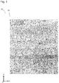
- Fig. 1 is a partially enlarged plan view of a decorative material 10 according to one embodiment on a pattern formation layer 12 side. If necessary, for convenience, Fig. 1 and the following drawings also show the arrows indicating directions (x, y, z), that is, a coordinate system.
- the direction xy is an in-plane direction of the decorative material 10
- the direction z is a thickness direction thereof.
- Fig. 1 is a (plan) view of the decorative material 10 on the pattern formation layer 12 side particularly in the direction z.
- a pattern formation layer 12 is formed so as to give the surface as a whole, an external appearance with depressions like cracks present in the surface which is a style of so-called "burned cedar" of suitably charring the surface of a cedarwood board.
- the mode to be expressed in the present disclosure is not limited to a burned cedar style.
- the targets include a style of a burnt wooden board of charring the surface of a wooden board other than a cedar, a style of brickwork, and tiling which have joints, a style of a fabric grain having a large number of fibrous depressions, and a style of a leather grain having a large number of wrinkle-like depressions.
- depressions of predetermined lengths extending in a specified direction are expressed by grooves 13 inside which ink parts 14 specified by the present invention are disposed.
- specified angles ⁇ 1 and ⁇ 2 in the specified cross section, and the grooves 13 inside which the specified ink parts 14 are disposed lead to a concentration gradient (or concentration distribution) of ink in the grooves in the direction orthogonal to the direction where the grooves extend.
- concentration gradient or concentration distribution
- the direction where the grooves 13 extend (the direction Y in Fig.
- the specified angles ⁇ 1 and ⁇ 2 in the specified cross section, and the grooves 13 inside which the specified ink parts 14 are disposed lead to a concentration gradient (or concentration distribution) of ink in the grooves in the direction orthogonal to the direction where the grooves extend.
- concentration gradient or concentration distribution
- the specified angles ⁇ 1 and ⁇ 2 in the specified cross section, and the grooves 13 inside which the specified ink parts 14 are disposed lead to a concentration gradient (or concentration distribution) of ink in the grooves in the direction orthogonal to the direction where the grooves extend.
- concentration gradient or concentration distribution
- the specified angles ⁇ 1 and ⁇ 2 in the specified cross section, and the grooves 13 inside which the specified ink parts 14 are disposed lead to a concentration gradient (or concentration distribution) of ink in the grooves in the direction orthogonal to the direction where the grooves extend.
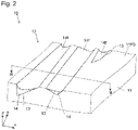
- Fig. 2 is a partially enlarged perspective view of the decorative material 10 which is schematically shown for explaining the form of the pattern formation layer 12.
- Fig. 3 is a cross-sectional view in the thickness direction, which is taken along the line III-III parallel to the direction x of Fig. 2 .
- the decorative material 10 has a substrate 11, and the pattern formation layer 12 provided on one face 11FS (an upper face in Fig. 2 , or a face on the positive side in the z-axis direction in the coordinate system) of the substrate 11. Accordingly, in this embodiment, one face of the substrate 11 is formed so as to function as the pattern formation layer 12.
- the substrate 11 itself has a single layer constitution, and is also used as the pattern formation layer 12.
- the present invention may have the embodiment of a two-layer constitution of laminating both the substrate 11 and the pattern formation layer 12 as separate independent layers.
- the substrate 11 is a sheet member having the functions of holding the pattern formation layer 12, and giving the decorative material 10 strength to retain the shape of the decorative material 10.
- the substrate 11 may be in any form of a film, a sheet and a board.
- a thin member is referred to as a film, a sheet or a board in the order of a relatively less thickness.
- the difference of the substrate according to the thickness is not an essential or important matter. Therefore, even if a film, a sheet or a board is randomly read as any other term thereamong in the present description, the present invention never changes essentially, and claims never change interpretively.
- the material of the substrate 11 is not particularly limited as long as the substrate 11 has the same functions as a conventionally known decorative material.
- the material of the substrate include polyolefin resins such as polyethylene, polypropylene, olefinic thermoplastic elastomers, and ionomers; acrylic resins such as polymethyl methacrylate, and polybutyl methacrylate; thermoplastic polyester resins such as polyethylene terephthalate, polybutylene terephthalate, polyethylene naphthalate, ethylene glycol-terephthalic acid-isophthalic acid copolymers, terephthalic acid-ethylene glycol-1,4 cyclohexanedimethanol copolymers, and various polyester-based thermoplastic elastomers; thermoplastic urethane resins; vinyl chloride resins such as, polyvinyl chloride, vinyl chloride-vinyl acetate copolymers, and ethylene-vinyl chloride copolymers; thermoplastic resins such as polycarbonate,
- the substrate When made from a resin, the substrate may be colored by any known colorant.
- a paper, a nonwoven fabric, a metal, a wood, a ceramic, a glass, a cement, a stone, or the like may be also used in the form of a sheet, a board, a 3D object, or the like by suitably laminating them onto any of the above resin materials.
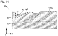
- the substrate is formed of any material of "paper” and the following, it is difficult to form grooves therein compared to the case of a resin substrate, and thus the groove shape, processing conditions, etc. are often limited. Therefore, the substrate of any of these materials is preferably formed to have a two-layer (laminated) constitution as in Fig. 14 , that is, the constitution of laminating the above described resin layer onto a face of the substrate on the side where grooves are to be formed, that is, on the one face 11FS side, as the pattern formation layer 12.
- the thickness of the substrate is not particularly limited.
- a sheet or film substrate having a thickness of approximately 20 ⁇ m to 1000 ⁇ m is used.
- a board substrate having a thickness of approximately 1 mm to 20 mm is used.
- the pattern formation layer 12 is provided on the one face 11FS of the substrate 11 (when the substrate 11 is also used as the pattern formation layer 12, the vicinity of the one face 11FS of the substrate 11 is the pattern formation layer 12), and provides a surface of the decorative material with a desired pattern.
- the pattern formation layer 12 is formed to be suitable for expressing a pattern of a burned cedar style on the decorative material 10.
- the pattern formation layer 12 is provided with a plurality of the grooves 13, and the ink parts 14 disposed inside the grooves 13.
- the grooves 13 are grooves of cross-sectional shapes having features described later. These grooves extend in the direction y in the drawings such as Fig. 2 .
- a plurality of the grooves of different widths sizes in the direction x, which is orthogonal to the extending direction of the grooves
- different depths sizes in the thickness direction of the substrate 11, or in the direction z in the drawings such as Fig. 2
- different shapes of the wall surfaces thereof, and the like are provided in the xy plane, to show a predetermined outer shape (outer shape of a burned cedar style in the present embodiment).
- the widths of the grooves 13 are not particularly limited, but are each preferably 200 ⁇ m to 1000 ⁇ m. This makes it difficult to visually recognize them as grooves, and makes it possible to dispose the ink parts 14 having desired shapes in the grooves 13.
- the width W in any one of the grooves 13 is not necessarily fixed, but may vary all over the extending direction of the grooves (direction y).
- the depths of the grooves 13 are not particularly limited either, but are each preferably 30 ⁇ m to 80 ⁇ m. This makes it possible to dispose the ink parts 14 of desired forms in the grooves 13 as obtaining the effect of expressing a pattern by shades, particularly reproducing the external appearance of cracks or level differences on the charred surface of a wooden board, typically, a surface of burned cedar.
- the depth D in any one of the grooves 13 is not necessarily fixed, but may vary all over the extending direction of the grooves (direction y).
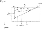
- Fig. 4 shows an enlarged view focusing on one of the grooves 13 in Fig 3 .
- hatching is omitted in Fig. 4 and the following.
- the groove 13 includes a first slope part S 1 extending from one side end part in the width direction W 1 to a deepest part Di, and a second slope part S 2 extending from the other side end part in the width direction W 2 to the deepest part D 1 .
- a line segment W 12 connecting W 1 and W 2 , a line segment W 1 D 1 connecting W 1 and D 1 (same as S 1 in this embodiment), and a line segment W 2 D 1 connecting W 2 and D 1 (same as S 2 in this embodiment) are imagined.
- ⁇ 1 is larger than ⁇ 2 . That is, the first slope part S 1 and the second slope part S 2 are formed so as not to be symmetrical to but to be different from each other, across the deepest part D 1 .
- Fig. 5 shows an embodiment of the deepest part having a predetermined width.
- the line segment W 1 D 1 and the line segment W 2 D 1 may be defined assuming that the center of the width of the deepest part is the deepest part D 1 .
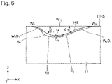
- Fig. 6 shows an embodiment of a curved first slope part S 1 and a curved second slope part S 2 .
- the line segment W 1 D 1 and the line segment W 2 D 1 may be also defined in the same manner as described above and as Fig. 5 .
- the line segment W 1 D 1 and the line segment W 2 D 1 are represented by (replaced with) smoothed first slope part S 1 and smoothed second slope part S 2 that are actually not straight lines.
- Fig. 7 shows an embodiment of stepped first slope part S 1 and stepped second slope part S 2 (hereinafter may be simply abbreviated as “slope part S 1 " and “slope part S 2 ”) in a cross section in the direction orthogonal to the extending direction of the groove 13 (hereinafter may be simply referred to as "cross section").
- the line segment W 1 D 1 and the line segment W 2 D 1 may be also defined in the same manner as described above for obtaining the angles ⁇ 1 and ⁇ 2 assuming that the first slope part S 1 and the second slope part S 2 , which are not straight lines, are smoothed and used as representative slope parts (replacements).
- both the slope part S 1 and the slope part S 2 are stepped parts as described above. Only one of the slope parts (for example, only the first slope part S 1 ) may be a stepped part, and the other slope part (for example, the second slope part S 2 ) may have a linear or curved cross-sectional shape as shown in Fig. 4 or 6 .
- the embodiment of at least one of the slope part S 1 and the slope part S 2 having a stepped shape in the cross-sectional shape of the groove 13 is particularly preferable in view of reproducing the external appearance of a minute structure of cracks or level differences on the charred surface of a wooden board, typically, a surface of burned cedar.
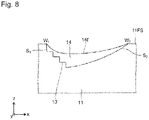
- Figs. 8 and 9 show other examples of stepped slopes.
- the first slope part S 1 has a stepped portion, but the second slope part S 2 is formed of a gentle continuously curved slope without any stepped portions.
- Fig. 9 shows an example of the first slope part S 1 and the second slope part S 2 each of which partially has a stepped shape and the rest of which does not have a stepped shape.
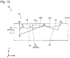
- Fig. 10 shows an embodiment of different positions between W 1 and W 2 in the thickness direction (positions in the direction z) in the groove 13.
- the line segment W 12 connecting W 1 and W 2 the line segment W 1 D 1 connecting W 1 and D 1 (same as S 1 in this embodiment), and the line segment W 2 D 1 connecting W 2 and D 1 (same as S 2 in this embodiment) are also imagined.
- ⁇ 1 is larger than ⁇ 2 . That is, the first slope part S 1 and the second slope part S 2 are formed so as not to be symmetrical to but to be different from each other, across the deepest part D 1 .
- the position of W 1 is higher than that of W 2 .
- the present invention is not limited to this.
- the position of W 1 may be lower than that of W 2 .
- the first slope part S 1 and the second slope part S 2 may be according to any different embodiments from the above-described embodiments.
- the first slope part S 1 may be according to a different embodiment from the second slope part S 2 .
- ⁇ 1 and ⁇ 2 are also defined in the same manner as described above.
- the range of ⁇ 1 is not particularly limited, but is preferably 10° to 45°. With ⁇ 1 more than 45°, ink on the bottom of the groove 13 may be scraped off and have gone when the groove 13 are filled with ink so that the ink is disposed therein to form the ink part 14 by wiping described later, which lessens the effect of giving the groove 13 the external appearance of shades, and a three-dimensional effect of the decorative material. ⁇ 1 less than 10° causes the ink amount of the ink part 14 itself to be small, which may lessen the effect of giving the groove 13 the external appearance of shades, and a three-dimensional effect of the decorative material.
- the range of ⁇ 2 is not particularly limited either, but is preferably 5° to 30°. ⁇ 2 more than 30° results in a small angular difference between ⁇ 1 (up to 45° in the preferred range) and ⁇ 2 , further a small difference between the first slope part S 1 and the second slope part S 2 in ink thickness of the ink part 14, and a slight concentration gradient of the ink of the ink part 14 in the groove 13. As a result, the effect of giving the groove 13 the external appearance of shades, and a three-dimensional effect of the decorative material may lessen. ⁇ 2 less than 5° causes the ink amount of the ink part 14 itself to be small, which may lessen the effect of giving the groove 13 the external appearance of shades, and a three-dimensional effect of the decorative material.
- the difference ( ⁇ 1 - ⁇ 2 ) obtained by subtracting ⁇ 2 from ⁇ 1 is preferably 3° to 35°.
- ( ⁇ 1 - ⁇ 2 ) of 7° or more leads to a remarkable effect of giving the groove 13 the external appearance of shades, and a three-dimensional effect of the decorative material.
- ( ⁇ 1 - ⁇ 2 ) less than 3° results in a small difference between the first slope part S 1 and the second slope part S 2 in ink thickness of the ink part 14, and a slight concentration gradient of the ink of the ink part 14 in the groove 13.
- the effect of giving the groove 13 the external appearance of shades, and a three-dimensional effect of the decorative material may lessen.
- the shape of the first slope part S 1 , the shape of the second slope part S 2 , ⁇ 1 and ⁇ 2 , and the difference between ⁇ 1 and ⁇ 2 are not necessarily fixed, but may vary all over the extending direction of the grooves 13 (direction y). Thus, the positional relationship between ⁇ 1 and ⁇ 2 may be reversed all over the extending direction. In this case, the relationship between the magnitudes of ⁇ 1 and ⁇ 2 may be also considered in the same way as the above.
- the direction in which the groove 13 extends in a plan view is not strictly but preferably based on the direction y.
- the direction orthogonal to this extending direction is preferably set as the direction x.
- the direction where the groove 13 extends is a direction crossing, and preferably orthogonal to an annual ring pattern (including a cross grain and a straight grain) in the design pattern of the printed layer 16c or a direction where a wood grain of vessel grooves extends (tree height direction), as described above.
- Such an extending direction of the groove 13 makes it possible to reproduce the external appearance of the design of cracks or level differences on a carbonized wood portion which are particular to the surface of a burned cedar board.
- the direction in which the groove 13 extends is not necessarily restricted strictly either. It is permitted that the groove 13 inclines to some extent toward the direction x from the direction y, or is a non-linear or curved groove.
- Examples of a non-linear or curved groove typically includes the following (1) or (2).
- the direction where the groove 13 extends is a direction preferably crossing, and more preferably orthogonal to an annual ring pattern in the design pattern of the printed layer 16c or a direction where a wood grain of vessel grooves extends even when the groove 13 has a non-linear or curved shape represented by the following (1) or (2), in a plan view.
- the groove 13 extends in a specified direction (e.g., the direction y), and has a shape of meandering with respect to the direction (direction x) orthogonal to the extending direction thereof.
- the shape of the groove 13 in a plan view may be a curve obtained by modulating any one or more of the amplitudes, wavelengths (spatial frequencies), and phases of these sine wave, square wave, staircase wave, etc. as necessary. Such a shape may be suitably deformed or distorted.
- the shape of the groove 13 in a plan view is formed of a line meandering in the direction orthogonal to the extending direction of a cliff line, a course of a river, or the like extracted from a map, an aerial photograph, or the like.
- the shape has a scale or magnification as necessary dimensionally, and may be properly retouched if necessary.
- both the end parts of the groove 13 may end without reaching the periphery that forms the external shape of the decorative material 10 (outer edge; four sides if the decorative material is a quadrangle in a plan view); one of the end parts may reach the periphery of the decorative material 10 but the other end part may end without reaching the periphery of the decorative material 10; and both the end parts may reach the periphery of the decorative material 10.
- first slope parts S 1 may be next to the second slope parts S 2 ; and the first slope parts S 1 may be next to each other, and the second slope parts S 2 may be next to each other.
- the ink parts 14 are portions formed of ink disposed in the grooves 13.
- the decorative material 10 with such ink can have a different external appearance and tactile sense from that with the grooves 13 only.
- the form of the ink parts 14 may be, for example, as follows.
- a surface 14f of each of the ink parts 14 is formed to cover the first and second slope parts S 1 and S 2 , and have the deepest portion at any place between the end part W 1 and the end part W 2 . That is, the depressed surface 14a of the ink part 14 is in a concave form as shown in Fig. 2 toward a direction where the groove is cut, and where an observer sees the decorative material (e.g., the positive direction of the z-axis in Fig. 2 ).
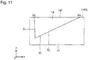
- the ink part 14 covers the first and second slope parts S 1 and S 2 , and keeps approximately the same z position between the end part W 1 and the end part W 2 , to be flat.
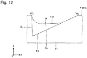
- the surface 14f of the ink part 14 covers the first slope part S 1 and part of the second slope part S 2 , and is in a concave form as shown in Fig. 12 toward a direction where the groove is cut and where an observer sees the decorative material (e.g., the positive direction of the z-axis in Fig. 12 ); and a part of the second slope part S 2 is exposed.
- the ink part 14 covers part of the first slope part S 1 and part of the second slope part S 2 , and both the first slope part S 1 and the second slope part S 2 are partially exposed.
- first slope part S 1 and the second slope part S 2 are stepped parts, for example, as shown in Fig. 13 , it may be also considered that no ink part 14 is formed on stepped outside corners 13oc, and the outside corners 13 OC are exposed.
- the thickness of the ink part on the first slope part S 1 side can be made to be thicker than that on the second slope part S 2 side. More specifically, the average thickness of the ink part on the first slope part S 1 is made to be thicker than that on the second slope part S 2 .
- the difference between the thickness of the ink part on the first slope part S 1 side (relatively thick) and that on the second slope part S 2 side (relatively thin) leads to a good effect of giving the groove 13 the external appearance of shades, and a three-dimensional effect of the decorative material, which is preferable.
- the ink thickness difference is more preferably at least 3 ⁇ m.
- the ink thickness difference of 1 ⁇ m or less results in a slight concentration gradient of the ink of the ink part 14 in the groove 13. As a result, the effect of giving the groove 13 the external appearance of shades, and a three-dimensional effect of the decorative material may lessen.
- the "average thickness of the ink part on the first slope part S 1 " is defined as a value obtained by dividing the cross-sectional area of the ink part present on the first slope part S 1 by the length of the first slope part S 1 in the cross section; and the “average thickness of the ink part on the second slope part S 2 " is defined as a value obtained by dividing the cross-sectional area of the ink part present on the second slope part S 2 by the length of the second slope part S 2 in the cross section.
- the shape of the ink part 14 is not necessarily fixed, but may vary all over the extending direction of the groove 13.
- the ink parts 14 disposed in a plurality of the grooves 13 may each have different forms.
- Such a variation of the shapes of the ink parts 14 expectably brings about a more particular visual effect.
- the mode of filling the grooves 13 with ink varies. More specifically, for example, the difference between the inclination angle ( ⁇ 1 ) of the first slope part and the inclination angle ( ⁇ 2 ) of the second slope part affects the change in the fill rate of the grooves 13 with ink.
- the material of the ink forming the ink parts there is no particular limitation on the material of the ink forming the ink parts.
- a known ink may be used.
- An example of the ink is a vehicle containing any one or more of a color pigment, a matte pigment, a dye, and the like.
- the vehicle may be suitably selected from various thermoplastic resins, thermosetting resins, and ionizing radiation curable resins.
- the change in the form of any one of the ink parts 14 on the first slope part S 1 side is different from that on the second slope part S 2 side since, because of the forms of the first slope parts S 1 and the second slope parts S 2 of the grooves 13 and the forms of the ink parts 14 disposed therein in combination, the thickness of any one of the ink parts 14 sequentially changes all over the width direction of the groove 13; the shape on one side in the width direction is asymmetric to that on the other side, across the deepest part; the thickness of any one of the ink parts 14 on the first slope part S 1 side tends to be thicker than that on the second slope part S 2 side; etc. Therefore, the intensity and direction of the reflected light of the decorative material 10 are different from conventional ones, and thus the decorative material 10 has a visually different effect from conventional one. Likewise, the tactile sense that the decorative material 10 provides is also different from conventional one.
- the difference between W 1 and W 2 , and D 1 can produce a three-dimensional effect, and makes a shading expression rich.
- the above described decorative material 10 is an example of a single layer constitution of using the substrate 11 also as the pattern formation layer 12, and forming the grooves 13 and the ink layers 14 on the surface of the substrate 11 itself.
- the layer constitution of the decorative material is not limited to the above, but may be a laminated constitution of laminating, onto the substrate 11, the pattern formation layer 12 as another layer made from a material different from the substrate 11. Any necessary layer may be further laminated suitably, in addition to these substrate 11 and pattern formation layer 12 of a single layer or laminated constitution.
- Figs. 14 to 16 are explanatory views. Every drawing is viewed from the same point as Fig. 3 .
- Fig. 14 shows a decorative material 10a of laminating the pattern formation layer 12 prepared as another layer made from a material different from the substrate 11, onto the one surface 11FS (upper face in this drawing) of the substrate 11.
- This pattern formation layer 12 may be made from the same material as the substrate 11, and the thickness thereof may be different from the substrate 11.
- the substrate 11 is formed to be a colored concealing layer
- the pattern formation layer 12 is formed to be a colorless or colored transparent layer, which make it possible to show a particular texture.
- an additional substrate may be further laminated on the substrate 11.
- Fig. 15 shows a decorative material 10b of laminating a protective layer 15b made from a transparent resin onto the outermost surface of a layer that functions as the pattern formation layer 12 in the substrate 11, and that is in the vicinity of the upper side in Fig. 15 .
- the resin constituting the protective layer 15b is not particularly limited, but transparent one among the materials listed in the description on the substrate 11 may be used.
- Fig. 16 shows a decorative material 10c of laminating the printed layer 16c onto a face opposite to a layer that functions as the pattern formation layer 12 in the substrate 11, and that is in the vicinity of the upper side in Fig. 16 , that is, on the lower side in Fig. 16 .
- the printed design is shown as a design of the decorative material 10c when the substrate 11 is colorless or colored transparent, which is a particular expression.
- the design pattern of the printed layer 16c is selected according to the design which the decorative material 10 is aimed at reproducing the external appearance of.
- a design pattern of a wood grain is adopted as the design pattern of the printed layer 16c.
- a wood grain pattern approximating the external appearance of a design of a burned cedar board when superimposed on the pattern of the grooves 13 and the ink parts 14 disposed in the grooves 13 to be seen is selected. At this time, it is not always necessary to select a wood grain pattern of a natural burned cedar board.
- the printed layer 16c may have a pattern of a wood grain other than a burned cedar board as long as anyone seeing the decorative material 10 can feel the external appearance of the design of a burned cedar board when observing three superimposed elements of the grooves 13, the ink parts 14, and the wood grain pattern of the printed layer 16c.
- a design pattern of tiling or a brickwork style is adopted as the design pattern of the printed layer 16c.
- a design pattern of a fabric grain style is adopted as the design pattern of the printed layer 16c.
- a design pattern of a leather grain style is adopted as the design pattern of the printed layer 16c.
- the decorative material 10 includes the structure comprising: the grooves 13 characterized by the angles ⁇ 1 and ⁇ 2 , the average thicknesses of the ink parts, etc. as described above; and the ink parts 14 disposed in the grooves.
- the ratio of the total value ⁇ L S of the length(s) of the groove(s) 13 that satisfy/satisfies the conditions particular to the present disclosure (such as angles ⁇ 1 and ⁇ 2 , and the average thicknesses of the ink parts), to the ground total value ⁇ L total of the lengths of all the grooves 13 measured in the extending direction of the respective grooves 13 present on the surface of the decorative material 10 is defined as ⁇ L S / ⁇ L total .
- ⁇ L S / ⁇ L total ⁇ 3/10, and more preferably, ⁇ L S / ⁇ L total ⁇ 5/10.
- the grooves 13 are limited to those corresponding to cracks or portions of level differences of a carbonized wood on the surface of a burnt wood board, typically, a burnt cedar board, that is, when ⁇ L total is a ground total value of the extending lengths of the grooves 13 corresponding to cracks or portions of level differences of a carbonized wood on the surface of a burnt wood board, and ⁇ L S is a total value of the length(s) of the groove(s) 13 that satisfy/satisfies the conditions particular to the present disclosure in L total , preferably, ⁇ L S / ⁇ L total ⁇ 7/10, and more preferably, ⁇ L S / ⁇ L total ⁇ 8/10.
- the layer constitution may be made by the second substrate (a third substrate may be further present), the protective layer, and the printed layer suitably in combination.
- Examples of the layer constitution of the decorative material include: a layer constitution of laminating the second substrate, the printed layer, and the substrate (pattern formation layer) in this order; a layer constitution of laminating the second substrate, the substrate (pattern formation layer), and the protective layer in this order; and a layer constitution of laminating the second substrate, the printed layer, the substrate (pattern formation layer), and the protective layer in this order.
- the method of manufacturing a decorative material is not limited to this.
- the manufacturing method described as follows includes a step of creating an original image, a step of creating a block copy image, a step of making a board, a step of forming grooves of a pattern formation layer, and a step of filling with ink.
- a pattern (pattern of a burned cedar style) in a plan view which is to be expressed by the grooves in the pattern formation layer 12 is obtained and used as an original image.
- a pattern in a plan view which is to be expressed on the surface of the substrate 11 is obtained as the density (lights and shades) of the image, and used as a block copy image.
- the block copy image is preferably in the form of digital data.
- digital data that is formed by: aligning pixels in a two-dimensional coordinate plane (x, y); and allocating a density value unique to each pixel, to each corresponding pixel is obtained by using a technique of reading the original image with a scanner, and subjecting the read image to AD conversion.
- this digital data may be used.
- an embossed board (molding die for decorative materials) having a pattern of a shape using the grooves 13 in a plan view, on a surface thereof is made based on the block copy image.
- the step of producing a pattern of bumps and depressions includes the following procedures (1) to (5).
- a metal roll 20 for chasing embossed boards as shown in Fig. 17 is prepared.
- the metal roll 20 is obtained by plating a copper layer on a surface of a hollow iron cylinder that has a rotation driving axis (shaft) 21 at both end portions in the axis direction.
- the surface of the metal roll 20 is polished by a whetstone to be a rough surface, and then is treated so that specular reflection of laser light for chasing is prevented from deteriorating chasing efficiency.
- the surface of the metal roll 20, which is prepared in the step (2), is chased using a laser light direct chaser based on the image data of the pattern of bumps and depressions, which is created in the step (1), as schematically shown in Fig. 17 .
- a shape that the pattern of bumps and depressions on the embossed board is that of reversing the relationship between bumps and depressions on the pattern of bumps and depressions by the grooves 13 in the decorative material, and may be considered the same as the decorative material.
- the metal roll 20 is driven by an electric motor via the rotation driving axis 21, to be rotated as using the rotation driving axis 21 as the central axis.
- the surface of the metal roll 20 is scanned with laser light P that is emitted from a laser head 22.
- the irradiation with the laser light is carried out in a state where liquid for chasing T is sprayed from an exhaust port for liquid for chasing 23 onto an area irradiated with the laser light which is on the surface of the metal roll 20, in order to prevent powder converted from the vaporized metal from remaining or adhering to the surface of the metal roll 20.
- electropolishing is carried out to remove the residue of the metal adhered to the surface of the metal roll 20.
- a chromium layer having a thickness of 10 ⁇ m is formed on the surface of the metal roll by plating.
- the foregoing makes it possible to obtain a board (die for molding decorative materials.
- the embossed board in the present embodiment including a surface profile of bumps and depressions that is formed of inverse bumps and depressions to the pattern of bumps and depressions using the grooves 13 which is formed on the surface of the pattern formation layer 12.
- the grooves 13 are obtained by embossing the substrate 11 using the made board (embossed board).
- the embossing may be carried out by any suitable known method without any particular limitations. Examples of typical embossing methods include the following.
- a resin sheet made from a thermoplastic resin such as polyolefin resins is used as the substrate.
- This substrate is heated and softened.
- the embossed board is pressed onto a surface of this substrate to shape the pattern of bumps and depressions on the surface of the embossed board, on the surface of the resin sheet.
- the resin sheet is cooled and cured, and then the pattern of bumps and depressions thereon is fixed. Thereafter the resin sheet, on which the pattern of bumps and depressions is formed, is removed from the embossed board.
- thermoplastic resin is typically used as the materials of the substrates used in the embossing methods (A) to (C).
- An ionizing radiation curable resin is typically used as the material of the substrate used in the embossing method (D).
- a thermosetting resin is typically used as the material of the substrate used in the embossing method (E).
- the grooves 13 formed on the surface of the substrate 11 are filled with ink, and the ink is disposed in the groove 13 in a desired thickness distribution to form the ink parts 14.
- This is performed by: supplying (uncured) an ink material to be the ink parts 14, to the face of the substrate 11 where the grooves 13 are formed, by a coating method such as curtain flow coating and roll coating; and scratching this face with a doctor blade, a squeegee, a sponge roller, or the like to remove (wipe) excess ink that is outside the grooves 13.
- a coating method such as curtain flow coating and roll coating
- Such a method itself of filling with and disposing ink in the grooves is a method known as so-called "wiping".
- the method is carried out by moving a doctor blade 30 in the direction (direction x) orthogonal to the direction (direction y) where the grooves 13 extend. That is, the doctor blade 30 is moved toward the direction x, which is orthogonal to the direction y, where the grooves 13 extend.
- the thickness of any one of the ink parts of the grooves 13 on the first slope part S 1 side is more than that on the second slope part S 2 side.
- the ink is cured by a suitable method, so that the decorative material 10 is obtained.
- the use of the above described decorative material is not particularly limited, but examples thereof include interior materials for buildings such as walls, floors, and ceilings; exterior materials for buildings such as exterior walls, roofs, gates, walls, and fences; fittings such as doors, window frames, and door frames; facing materials for millwork such as crown moldings, skirting boards, and handrails; facing materials for housings of home appliances such as TV sets and refrigerators, and of office equipment such as copying machines; facing materials for furniture such as chests of drawers; facing materials for containers such as boxes and resin bottles; interior and exterior materials for vehicles etc.; and interior and exterior materials for vessels.
Landscapes
- Engineering & Computer Science (AREA)
- Architecture (AREA)
- Civil Engineering (AREA)
- Structural Engineering (AREA)
- Ceramic Engineering (AREA)
- Life Sciences & Earth Sciences (AREA)
- Wood Science & Technology (AREA)
- Laminated Bodies (AREA)
- Finishing Walls (AREA)
Applications Claiming Priority (4)
| Application Number | Priority Date | Filing Date | Title |
|---|---|---|---|
| JP2019176742 | 2019-09-27 | ||
| JP2019176897 | 2019-09-27 | ||
| JP2020159476A JP7654947B2 (ja) | 2019-09-27 | 2020-09-24 | 化粧材 |
| PCT/JP2020/036431 WO2021060530A1 (ja) | 2019-09-27 | 2020-09-25 | 化粧材 |
Publications (2)
| Publication Number | Publication Date |
|---|---|
| EP4036348A1 true EP4036348A1 (de) | 2022-08-03 |
| EP4036348A4 EP4036348A4 (de) | 2022-12-07 |
Family
ID=75166320
Family Applications (1)
| Application Number | Title | Priority Date | Filing Date |
|---|---|---|---|
| EP20869351.5A Withdrawn EP4036348A4 (de) | 2019-09-27 | 2020-09-25 | Dekoratives material |
Country Status (5)
| Country | Link |
|---|---|
| US (1) | US20220332082A1 (de) |
| EP (1) | EP4036348A4 (de) |
| CN (1) | CN114423620B (de) |
| AU (1) | AU2020352135A1 (de) |
| WO (1) | WO2021060530A1 (de) |
Families Citing this family (4)
| Publication number | Priority date | Publication date | Assignee | Title |
|---|---|---|---|---|
| JP2023046957A (ja) * | 2021-09-24 | 2023-04-05 | 大日本印刷株式会社 | 化粧材及び化粧材の製造方法 |
| US12403680B2 (en) | 2021-09-24 | 2025-09-02 | Dai Nippon Printing Co., Ltd. | Decorative material |
| USD1015576S1 (en) * | 2021-10-07 | 2024-02-20 | James Hardie Technology Limited | Textured fiber cement cladding panel |
| CN117082769B (zh) * | 2022-05-10 | 2024-10-29 | 比亚迪股份有限公司 | 一种装饰基板及其制备方法和应用 |
Family Cites Families (16)
| Publication number | Priority date | Publication date | Assignee | Title |
|---|---|---|---|---|
| JPS5787318A (en) | 1980-11-19 | 1982-05-31 | Toyo Ink Mfg Co Ltd | Forming method of uneven pattern |
| JP2975074B2 (ja) * | 1990-01-26 | 1999-11-10 | 大日本印刷株式会社 | 化粧材 |
| JPH05131800A (ja) * | 1991-10-09 | 1993-05-28 | Dainippon Printing Co Ltd | 化粧材及びその製造方法 |
| JP2931183B2 (ja) | 1993-07-23 | 1999-08-09 | 大日本印刷株式会社 | 凹凸フィルムの製造装置 |
| JP3380016B2 (ja) * | 1993-11-12 | 2003-02-24 | 大日本印刷株式会社 | 化粧板用賦形型の製造に使用するマスクフィルムの製造方法および該マスクフィルムを用いて製造した化粧板用賦形型 |
| JPH08291607A (ja) * | 1995-04-24 | 1996-11-05 | Hama Cast:Kk | 建築物用壁装材及び建築物の吹き付け塗装方法 |
| JP3189091B2 (ja) * | 1997-12-19 | 2001-07-16 | 広島化成株式会社 | コンクリート用化粧型枠、及びそれを使用した コンクリート表面の化粧施工方法 |
| JP2957566B1 (ja) * | 1998-07-24 | 1999-10-04 | ニチハ株式会社 | 建築板及びその施工構造 |
| JP2000038000A (ja) * | 1998-07-27 | 2000-02-08 | Dainippon Printing Co Ltd | エンボス化粧材 |
| JP2001239627A (ja) * | 2000-02-29 | 2001-09-04 | Dainippon Printing Co Ltd | エンボス化粧シート |
| JP2004060241A (ja) * | 2002-07-26 | 2004-02-26 | Nichiha Corp | 建築板及び建築板印刷装置 |
| BE1015550A5 (nl) * | 2003-06-04 | 2005-06-07 | Flooring Ind Ltd | Vloerpaneel en werkwijze voor het vervaardigen van dergelijk vloerpan eel. |
| EP2108524B1 (de) * | 2008-04-08 | 2011-03-16 | Flooring Industries Limited, SARL | Verfahren zur Herstellung beschichteter Paneele und beschichtetes Paneel |
| KR20110074390A (ko) * | 2009-12-24 | 2011-06-30 | 엘지이노텍 주식회사 | 입체감 형성 외장재 |
| JP6472848B1 (ja) * | 2017-08-31 | 2019-02-20 | 大建工業株式会社 | 無機質化粧板の製造方法 |
| KR20250012747A (ko) * | 2018-03-30 | 2025-01-24 | 다이니폰 인사츠 가부시키가이샤 | 부조 마감 나뭇결 화장재 |
-
2020
- 2020-09-25 EP EP20869351.5A patent/EP4036348A4/de not_active Withdrawn
- 2020-09-25 WO PCT/JP2020/036431 patent/WO2021060530A1/ja not_active Ceased
- 2020-09-25 CN CN202080065041.2A patent/CN114423620B/zh active Active
- 2020-09-25 AU AU2020352135A patent/AU2020352135A1/en active Pending
- 2020-09-25 US US17/641,327 patent/US20220332082A1/en not_active Abandoned
Also Published As
| Publication number | Publication date |
|---|---|
| CN114423620B (zh) | 2023-06-20 |
| WO2021060530A1 (ja) | 2021-04-01 |
| AU2020352135A1 (en) | 2022-03-31 |
| CN114423620A (zh) | 2022-04-29 |
| US20220332082A1 (en) | 2022-10-20 |
| EP4036348A4 (de) | 2022-12-07 |
Similar Documents
| Publication | Publication Date | Title |
|---|---|---|
| EP4036348A1 (de) | Dekoratives material | |
| WO2019066026A1 (ja) | 化粧材、及び該化粧材のための型 | |
| WO2019189407A1 (ja) | 化粧材 | |
| JP7294408B2 (ja) | 化粧材 | |
| JP7585674B2 (ja) | 化粧材 | |
| JP2000008538A (ja) | エンボス化粧材 | |
| WO2019194202A1 (ja) | 化粧材の製造方法 | |
| JP7386594B2 (ja) | 化粧材、化粧材の製造方法 | |
| JP7654947B2 (ja) | 化粧材 | |
| JPWO1995021060A1 (ja) | 木目導管溝の凹凸構造を再現した化粧材/エンボス版ならびにその作成方法および作成装置 | |
| JP2005153464A (ja) | 表面模様付容器 | |
| KR20200130860A (ko) | 화장재, 화장재의 제조 방법 | |
| JP7139650B2 (ja) | 化粧材 | |
| JP7402600B2 (ja) | 化粧材 | |
| JP7067203B2 (ja) | 化粧材 | |
| JP7581736B2 (ja) | 化粧材 | |
| US20220185008A1 (en) | Cosmetic material and production method for cosmetic material | |
| JP2024075728A (ja) | 化粧材 | |
| JP7543678B2 (ja) | 化粧材 | |
| JP7386593B2 (ja) | 化粧材、化粧材の製造方法 | |
| JP2020157551A (ja) | 化粧材 | |
| JPH0687200A (ja) | 化粧フィルム | |
| JPH0999534A (ja) | 化粧シートおよびその製造方法 | |
| JP2019171820A (ja) | 化粧材 | |
| JPH1170798A (ja) | エンボス化粧材 |
Legal Events
| Date | Code | Title | Description |
|---|---|---|---|
| STAA | Information on the status of an ep patent application or granted ep patent |
Free format text: STATUS: THE INTERNATIONAL PUBLICATION HAS BEEN MADE |
|
| PUAI | Public reference made under article 153(3) epc to a published international application that has entered the european phase |
Free format text: ORIGINAL CODE: 0009012 |
|
| STAA | Information on the status of an ep patent application or granted ep patent |
Free format text: STATUS: REQUEST FOR EXAMINATION WAS MADE |
|
| 17P | Request for examination filed |
Effective date: 20220317 |
|
| AK | Designated contracting states |
Kind code of ref document: A1 Designated state(s): AL AT BE BG CH CY CZ DE DK EE ES FI FR GB GR HR HU IE IS IT LI LT LU LV MC MK MT NL NO PL PT RO RS SE SI SK SM TR |
|
| A4 | Supplementary search report drawn up and despatched |
Effective date: 20221108 |
|
| RIC1 | Information provided on ipc code assigned before grant |
Ipc: B44C 1/26 20060101ALN20221102BHEP Ipc: B44F 11/06 20060101ALI20221102BHEP Ipc: B44F 9/02 20060101ALI20221102BHEP Ipc: B44C 1/24 20060101ALI20221102BHEP Ipc: B32B 3/30 20060101ALI20221102BHEP Ipc: E04C 2/20 20060101ALI20221102BHEP Ipc: E04F 13/08 20060101AFI20221102BHEP |
|
| DAV | Request for validation of the european patent (deleted) | ||
| DAX | Request for extension of the european patent (deleted) | ||
| STAA | Information on the status of an ep patent application or granted ep patent |
Free format text: STATUS: EXAMINATION IS IN PROGRESS |
|
| 17Q | First examination report despatched |
Effective date: 20240911 |
|
| STAA | Information on the status of an ep patent application or granted ep patent |
Free format text: STATUS: THE APPLICATION IS DEEMED TO BE WITHDRAWN |
|
| 18D | Application deemed to be withdrawn |
Effective date: 20251014 |