EP4029802A1 - Blattmaterialbehälter - Google Patents
Blattmaterialbehälter Download PDFInfo
- Publication number
- EP4029802A1 EP4029802A1 EP20864033.4A EP20864033A EP4029802A1 EP 4029802 A1 EP4029802 A1 EP 4029802A1 EP 20864033 A EP20864033 A EP 20864033A EP 4029802 A1 EP4029802 A1 EP 4029802A1
- Authority
- EP
- European Patent Office
- Prior art keywords
- layer
- film
- resin layer
- sheet material
- film layer
- Prior art date
- Legal status (The legal status is an assumption and is not a legal conclusion. Google has not performed a legal analysis and makes no representation as to the accuracy of the status listed.)
- Pending
Links
- 239000000463 material Substances 0.000 title claims abstract description 317
- 239000010410 layer Substances 0.000 claims abstract description 1531
- 229920005989 resin Polymers 0.000 claims abstract description 192
- 239000011347 resin Substances 0.000 claims abstract description 192
- 229920005672 polyolefin resin Polymers 0.000 claims abstract description 175
- 229920000219 Ethylene vinyl alcohol Polymers 0.000 claims abstract description 169
- 239000000945 filler Substances 0.000 claims abstract description 40
- 239000011229 interlayer Substances 0.000 claims abstract description 29
- 230000004308 accommodation Effects 0.000 claims abstract description 19
- 229920000092 linear low density polyethylene Polymers 0.000 claims description 238
- 239000004707 linear low-density polyethylene Substances 0.000 claims description 238
- 239000000470 constituent Substances 0.000 claims description 150
- 229920013716 polyethylene resin Polymers 0.000 claims description 68
- 229920001225 polyester resin Polymers 0.000 claims description 44
- 239000004645 polyester resin Substances 0.000 claims description 44
- 230000002093 peripheral effect Effects 0.000 claims description 32
- 239000004677 Nylon Substances 0.000 claims description 30
- 229920001778 nylon Polymers 0.000 claims description 30
- 230000032798 delamination Effects 0.000 abstract description 9
- 239000004715 ethylene vinyl alcohol Substances 0.000 description 82
- UFRKOOWSQGXVKV-UHFFFAOYSA-N ethene;ethenol Chemical compound C=C.OC=C UFRKOOWSQGXVKV-UHFFFAOYSA-N 0.000 description 81
- 229920000139 polyethylene terephthalate Polymers 0.000 description 67
- 239000005020 polyethylene terephthalate Substances 0.000 description 67
- 229920006223 adhesive resin Polymers 0.000 description 59
- 239000004840 adhesive resin Substances 0.000 description 59
- 239000012790 adhesive layer Substances 0.000 description 47
- 230000000052 comparative effect Effects 0.000 description 37
- 229920001684 low density polyethylene Polymers 0.000 description 28
- 239000004702 low-density polyethylene Substances 0.000 description 28
- VGGSQFUCUMXWEO-UHFFFAOYSA-N Ethene Chemical compound C=C VGGSQFUCUMXWEO-UHFFFAOYSA-N 0.000 description 27
- 238000001125 extrusion Methods 0.000 description 27
- 238000007789 sealing Methods 0.000 description 26
- 239000000853 adhesive Substances 0.000 description 25
- 230000001070 adhesive effect Effects 0.000 description 25
- 238000013461 design Methods 0.000 description 24
- 239000005001 laminate film Substances 0.000 description 24
- 238000007740 vapor deposition Methods 0.000 description 23
- 238000012360 testing method Methods 0.000 description 19
- -1 polyethylene terephthalate Polymers 0.000 description 15
- VYPSYNLAJGMNEJ-UHFFFAOYSA-N Silicium dioxide Chemical compound O=[Si]=O VYPSYNLAJGMNEJ-UHFFFAOYSA-N 0.000 description 14
- 229920006015 heat resistant resin Polymers 0.000 description 14
- 238000000034 method Methods 0.000 description 14
- 229920000098 polyolefin Polymers 0.000 description 12
- 229920002799 BoPET Polymers 0.000 description 10
- 238000000465 moulding Methods 0.000 description 9
- 238000012545 processing Methods 0.000 description 7
- 239000000377 silicon dioxide Substances 0.000 description 7
- 230000002708 enhancing effect Effects 0.000 description 6
- 239000012939 laminating adhesive Substances 0.000 description 6
- 238000012986 modification Methods 0.000 description 6
- 230000004048 modification Effects 0.000 description 6
- 229920005678 polyethylene based resin Polymers 0.000 description 6
- 238000004064 recycling Methods 0.000 description 6
- 238000010438 heat treatment Methods 0.000 description 5
- 238000003475 lamination Methods 0.000 description 5
- 239000005977 Ethylene Substances 0.000 description 4
- 239000004698 Polyethylene Substances 0.000 description 4
- 230000004888 barrier function Effects 0.000 description 4
- 239000011230 binding agent Substances 0.000 description 4
- 230000007423 decrease Effects 0.000 description 4
- 238000005304 joining Methods 0.000 description 4
- 229920000573 polyethylene Polymers 0.000 description 4
- 229910052782 aluminium Inorganic materials 0.000 description 3
- XAGFODPZIPBFFR-UHFFFAOYSA-N aluminium Chemical compound [Al] XAGFODPZIPBFFR-UHFFFAOYSA-N 0.000 description 3
- 238000005452 bending Methods 0.000 description 3
- 229920001577 copolymer Polymers 0.000 description 3
- 229920001903 high density polyethylene Polymers 0.000 description 3
- 239000004700 high-density polyethylene Substances 0.000 description 3
- 238000010030 laminating Methods 0.000 description 3
- 238000004519 manufacturing process Methods 0.000 description 3
- 229910052751 metal Inorganic materials 0.000 description 3
- 239000002184 metal Substances 0.000 description 3
- 239000002994 raw material Substances 0.000 description 3
- 239000007787 solid Substances 0.000 description 3
- 239000004952 Polyamide Substances 0.000 description 2
- XTXRWKRVRITETP-UHFFFAOYSA-N Vinyl acetate Chemical compound CC(=O)OC=C XTXRWKRVRITETP-UHFFFAOYSA-N 0.000 description 2
- 230000015572 biosynthetic process Effects 0.000 description 2
- 238000005520 cutting process Methods 0.000 description 2
- 230000000694 effects Effects 0.000 description 2
- 230000003203 everyday effect Effects 0.000 description 2
- 239000011888 foil Substances 0.000 description 2
- 239000007788 liquid Substances 0.000 description 2
- 229920001179 medium density polyethylene Polymers 0.000 description 2
- 239000004701 medium-density polyethylene Substances 0.000 description 2
- 239000000178 monomer Substances 0.000 description 2
- 229920006284 nylon film Polymers 0.000 description 2
- 239000003960 organic solvent Substances 0.000 description 2
- 229920002647 polyamide Polymers 0.000 description 2
- 229920000728 polyester Polymers 0.000 description 2
- 229920000642 polymer Polymers 0.000 description 2
- 239000002453 shampoo Substances 0.000 description 2
- 239000002356 single layer Substances 0.000 description 2
- 238000009864 tensile test Methods 0.000 description 2
- 229920000571 Nylon 11 Polymers 0.000 description 1
- 229920000299 Nylon 12 Polymers 0.000 description 1
- 229920002292 Nylon 6 Polymers 0.000 description 1
- 229920000305 Nylon 6,10 Polymers 0.000 description 1
- 229920002302 Nylon 6,6 Polymers 0.000 description 1
- 239000004743 Polypropylene Substances 0.000 description 1
- 230000002411 adverse Effects 0.000 description 1
- 239000003125 aqueous solvent Substances 0.000 description 1
- 235000013361 beverage Nutrition 0.000 description 1
- DQXBYHZEEUGOBF-UHFFFAOYSA-N but-3-enoic acid;ethene Chemical compound C=C.OC(=O)CC=C DQXBYHZEEUGOBF-UHFFFAOYSA-N 0.000 description 1
- 230000008859 change Effects 0.000 description 1
- 150000001875 compounds Chemical class 0.000 description 1
- 239000003599 detergent Substances 0.000 description 1
- 238000009820 dry lamination Methods 0.000 description 1
- 238000001035 drying Methods 0.000 description 1
- 239000005038 ethylene vinyl acetate Substances 0.000 description 1
- 239000002979 fabric softener Substances 0.000 description 1
- 239000012530 fluid Substances 0.000 description 1
- 239000006261 foam material Substances 0.000 description 1
- 235000013305 food Nutrition 0.000 description 1
- 239000008187 granular material Substances 0.000 description 1
- RZXDTJIXPSCHCI-UHFFFAOYSA-N hexa-1,5-diene-2,5-diol Chemical compound OC(=C)CCC(O)=C RZXDTJIXPSCHCI-UHFFFAOYSA-N 0.000 description 1
- 229920006262 high density polyethylene film Polymers 0.000 description 1
- 230000006872 improvement Effects 0.000 description 1
- 238000005259 measurement Methods 0.000 description 1
- 238000002844 melting Methods 0.000 description 1
- 230000008018 melting Effects 0.000 description 1
- 235000011837 pasties Nutrition 0.000 description 1
- 239000008188 pellet Substances 0.000 description 1
- 230000000149 penetrating effect Effects 0.000 description 1
- 229920003023 plastic Polymers 0.000 description 1
- 239000004033 plastic Substances 0.000 description 1
- 229920001200 poly(ethylene-vinyl acetate) Polymers 0.000 description 1
- 229920001155 polypropylene Polymers 0.000 description 1
- 238000003825 pressing Methods 0.000 description 1
- 230000002265 prevention Effects 0.000 description 1
- 238000007639 printing Methods 0.000 description 1
- 230000008569 process Effects 0.000 description 1
- 238000007127 saponification reaction Methods 0.000 description 1
- 239000000344 soap Substances 0.000 description 1
- 239000004711 α-olefin Substances 0.000 description 1
Images


Classifications
-
- B—PERFORMING OPERATIONS; TRANSPORTING
- B65—CONVEYING; PACKING; STORING; HANDLING THIN OR FILAMENTARY MATERIAL
- B65D—CONTAINERS FOR STORAGE OR TRANSPORT OF ARTICLES OR MATERIALS, e.g. BAGS, BARRELS, BOTTLES, BOXES, CANS, CARTONS, CRATES, DRUMS, JARS, TANKS, HOPPERS, FORWARDING CONTAINERS; ACCESSORIES, CLOSURES, OR FITTINGS THEREFOR; PACKAGING ELEMENTS; PACKAGES
- B65D65/00—Wrappers or flexible covers; Packaging materials of special type or form
- B65D65/38—Packaging materials of special type or form
- B65D65/40—Applications of laminates for particular packaging purposes
-
- B—PERFORMING OPERATIONS; TRANSPORTING
- B32—LAYERED PRODUCTS
- B32B—LAYERED PRODUCTS, i.e. PRODUCTS BUILT-UP OF STRATA OF FLAT OR NON-FLAT, e.g. CELLULAR OR HONEYCOMB, FORM
- B32B1/00—Layered products having a general shape other than plane
-
- B—PERFORMING OPERATIONS; TRANSPORTING
- B32—LAYERED PRODUCTS
- B32B—LAYERED PRODUCTS, i.e. PRODUCTS BUILT-UP OF STRATA OF FLAT OR NON-FLAT, e.g. CELLULAR OR HONEYCOMB, FORM
- B32B27/00—Layered products comprising a layer of synthetic resin
- B32B27/06—Layered products comprising a layer of synthetic resin as the main or only constituent of a layer, which is next to another layer of the same or of a different material
- B32B27/08—Layered products comprising a layer of synthetic resin as the main or only constituent of a layer, which is next to another layer of the same or of a different material of synthetic resin
-
- B—PERFORMING OPERATIONS; TRANSPORTING
- B32—LAYERED PRODUCTS
- B32B—LAYERED PRODUCTS, i.e. PRODUCTS BUILT-UP OF STRATA OF FLAT OR NON-FLAT, e.g. CELLULAR OR HONEYCOMB, FORM
- B32B27/00—Layered products comprising a layer of synthetic resin
- B32B27/18—Layered products comprising a layer of synthetic resin characterised by the use of special additives
- B32B27/20—Layered products comprising a layer of synthetic resin characterised by the use of special additives using fillers, pigments, thixotroping agents
- B32B27/205—Layered products comprising a layer of synthetic resin characterised by the use of special additives using fillers, pigments, thixotroping agents the fillers creating voids or cavities, e.g. by stretching
-
- B—PERFORMING OPERATIONS; TRANSPORTING
- B32—LAYERED PRODUCTS
- B32B—LAYERED PRODUCTS, i.e. PRODUCTS BUILT-UP OF STRATA OF FLAT OR NON-FLAT, e.g. CELLULAR OR HONEYCOMB, FORM
- B32B27/00—Layered products comprising a layer of synthetic resin
- B32B27/30—Layered products comprising a layer of synthetic resin comprising vinyl (co)polymers; comprising acrylic (co)polymers
- B32B27/306—Layered products comprising a layer of synthetic resin comprising vinyl (co)polymers; comprising acrylic (co)polymers comprising vinyl acetate or vinyl alcohol (co)polymers
-
- B—PERFORMING OPERATIONS; TRANSPORTING
- B32—LAYERED PRODUCTS
- B32B—LAYERED PRODUCTS, i.e. PRODUCTS BUILT-UP OF STRATA OF FLAT OR NON-FLAT, e.g. CELLULAR OR HONEYCOMB, FORM
- B32B27/00—Layered products comprising a layer of synthetic resin
- B32B27/32—Layered products comprising a layer of synthetic resin comprising polyolefins
-
- B—PERFORMING OPERATIONS; TRANSPORTING
- B32—LAYERED PRODUCTS
- B32B—LAYERED PRODUCTS, i.e. PRODUCTS BUILT-UP OF STRATA OF FLAT OR NON-FLAT, e.g. CELLULAR OR HONEYCOMB, FORM
- B32B27/00—Layered products comprising a layer of synthetic resin
- B32B27/34—Layered products comprising a layer of synthetic resin comprising polyamides
-
- B—PERFORMING OPERATIONS; TRANSPORTING
- B32—LAYERED PRODUCTS
- B32B—LAYERED PRODUCTS, i.e. PRODUCTS BUILT-UP OF STRATA OF FLAT OR NON-FLAT, e.g. CELLULAR OR HONEYCOMB, FORM
- B32B27/00—Layered products comprising a layer of synthetic resin
- B32B27/36—Layered products comprising a layer of synthetic resin comprising polyesters
-
- B—PERFORMING OPERATIONS; TRANSPORTING
- B32—LAYERED PRODUCTS
- B32B—LAYERED PRODUCTS, i.e. PRODUCTS BUILT-UP OF STRATA OF FLAT OR NON-FLAT, e.g. CELLULAR OR HONEYCOMB, FORM
- B32B3/00—Layered products comprising a layer with external or internal discontinuities or unevennesses, or a layer of non-planar form; Layered products having particular features of form
- B32B3/02—Layered products comprising a layer with external or internal discontinuities or unevennesses, or a layer of non-planar form; Layered products having particular features of form characterised by features of form at particular places, e.g. in edge regions
- B32B3/08—Layered products comprising a layer with external or internal discontinuities or unevennesses, or a layer of non-planar form; Layered products having particular features of form characterised by features of form at particular places, e.g. in edge regions characterised by added members at particular parts
-
- B—PERFORMING OPERATIONS; TRANSPORTING
- B32—LAYERED PRODUCTS
- B32B—LAYERED PRODUCTS, i.e. PRODUCTS BUILT-UP OF STRATA OF FLAT OR NON-FLAT, e.g. CELLULAR OR HONEYCOMB, FORM
- B32B3/00—Layered products comprising a layer with external or internal discontinuities or unevennesses, or a layer of non-planar form; Layered products having particular features of form
- B32B3/26—Layered products comprising a layer with external or internal discontinuities or unevennesses, or a layer of non-planar form; Layered products having particular features of form characterised by a particular shape of the outline of the cross-section of a continuous layer; characterised by a layer with cavities or internal voids ; characterised by an apertured layer
- B32B3/266—Layered products comprising a layer with external or internal discontinuities or unevennesses, or a layer of non-planar form; Layered products having particular features of form characterised by a particular shape of the outline of the cross-section of a continuous layer; characterised by a layer with cavities or internal voids ; characterised by an apertured layer characterised by an apertured layer, the apertures going through the whole thickness of the layer, e.g. expanded metal, perforated layer, slit layer regular cells B32B3/12
-
- B—PERFORMING OPERATIONS; TRANSPORTING
- B32—LAYERED PRODUCTS
- B32B—LAYERED PRODUCTS, i.e. PRODUCTS BUILT-UP OF STRATA OF FLAT OR NON-FLAT, e.g. CELLULAR OR HONEYCOMB, FORM
- B32B7/00—Layered products characterised by the relation between layers; Layered products characterised by the relative orientation of features between layers, or by the relative values of a measurable parameter between layers, i.e. products comprising layers having different physical, chemical or physicochemical properties; Layered products characterised by the interconnection of layers
- B32B7/04—Interconnection of layers
- B32B7/05—Interconnection of layers the layers not being connected over the whole surface, e.g. discontinuous connection or patterned connection
-
- B—PERFORMING OPERATIONS; TRANSPORTING
- B32—LAYERED PRODUCTS
- B32B—LAYERED PRODUCTS, i.e. PRODUCTS BUILT-UP OF STRATA OF FLAT OR NON-FLAT, e.g. CELLULAR OR HONEYCOMB, FORM
- B32B7/00—Layered products characterised by the relation between layers; Layered products characterised by the relative orientation of features between layers, or by the relative values of a measurable parameter between layers, i.e. products comprising layers having different physical, chemical or physicochemical properties; Layered products characterised by the interconnection of layers
- B32B7/04—Interconnection of layers
- B32B7/12—Interconnection of layers using interposed adhesives or interposed materials with bonding properties
-
- B—PERFORMING OPERATIONS; TRANSPORTING
- B65—CONVEYING; PACKING; STORING; HANDLING THIN OR FILAMENTARY MATERIAL
- B65D—CONTAINERS FOR STORAGE OR TRANSPORT OF ARTICLES OR MATERIALS, e.g. BAGS, BARRELS, BOTTLES, BOXES, CANS, CARTONS, CRATES, DRUMS, JARS, TANKS, HOPPERS, FORWARDING CONTAINERS; ACCESSORIES, CLOSURES, OR FITTINGS THEREFOR; PACKAGING ELEMENTS; PACKAGES
- B65D75/00—Packages comprising articles or materials partially or wholly enclosed in strips, sheets, blanks, tubes, or webs of flexible sheet material, e.g. in folded wrappers
- B65D75/008—Standing pouches, i.e. "Standbeutel"
-
- B—PERFORMING OPERATIONS; TRANSPORTING
- B65—CONVEYING; PACKING; STORING; HANDLING THIN OR FILAMENTARY MATERIAL
- B65D—CONTAINERS FOR STORAGE OR TRANSPORT OF ARTICLES OR MATERIALS, e.g. BAGS, BARRELS, BOTTLES, BOXES, CANS, CARTONS, CRATES, DRUMS, JARS, TANKS, HOPPERS, FORWARDING CONTAINERS; ACCESSORIES, CLOSURES, OR FITTINGS THEREFOR; PACKAGING ELEMENTS; PACKAGES
- B65D75/00—Packages comprising articles or materials partially or wholly enclosed in strips, sheets, blanks, tubes, or webs of flexible sheet material, e.g. in folded wrappers
- B65D75/52—Details
- B65D75/58—Opening or contents-removing devices added or incorporated during package manufacture
- B65D75/5861—Spouts
- B65D75/5866—Integral spouts
-
- B—PERFORMING OPERATIONS; TRANSPORTING
- B65—CONVEYING; PACKING; STORING; HANDLING THIN OR FILAMENTARY MATERIAL
- B65D—CONTAINERS FOR STORAGE OR TRANSPORT OF ARTICLES OR MATERIALS, e.g. BAGS, BARRELS, BOTTLES, BOXES, CANS, CARTONS, CRATES, DRUMS, JARS, TANKS, HOPPERS, FORWARDING CONTAINERS; ACCESSORIES, CLOSURES, OR FITTINGS THEREFOR; PACKAGING ELEMENTS; PACKAGES
- B65D75/00—Packages comprising articles or materials partially or wholly enclosed in strips, sheets, blanks, tubes, or webs of flexible sheet material, e.g. in folded wrappers
- B65D75/52—Details
- B65D75/58—Opening or contents-removing devices added or incorporated during package manufacture
- B65D75/5861—Spouts
- B65D75/5872—Non-integral spouts
- B65D75/5877—Non-integral spouts connected to a planar surface of the package wall
-
- B—PERFORMING OPERATIONS; TRANSPORTING
- B32—LAYERED PRODUCTS
- B32B—LAYERED PRODUCTS, i.e. PRODUCTS BUILT-UP OF STRATA OF FLAT OR NON-FLAT, e.g. CELLULAR OR HONEYCOMB, FORM
- B32B38/00—Ancillary operations in connection with laminating processes
- B32B38/0012—Mechanical treatment, e.g. roughening, deforming, stretching
- B32B2038/0028—Stretching, elongating
-
- B—PERFORMING OPERATIONS; TRANSPORTING
- B32—LAYERED PRODUCTS
- B32B—LAYERED PRODUCTS, i.e. PRODUCTS BUILT-UP OF STRATA OF FLAT OR NON-FLAT, e.g. CELLULAR OR HONEYCOMB, FORM
- B32B2250/00—Layers arrangement
- B32B2250/02—2 layers
-
- B—PERFORMING OPERATIONS; TRANSPORTING
- B32—LAYERED PRODUCTS
- B32B—LAYERED PRODUCTS, i.e. PRODUCTS BUILT-UP OF STRATA OF FLAT OR NON-FLAT, e.g. CELLULAR OR HONEYCOMB, FORM
- B32B2250/00—Layers arrangement
- B32B2250/03—3 layers
-
- B—PERFORMING OPERATIONS; TRANSPORTING
- B32—LAYERED PRODUCTS
- B32B—LAYERED PRODUCTS, i.e. PRODUCTS BUILT-UP OF STRATA OF FLAT OR NON-FLAT, e.g. CELLULAR OR HONEYCOMB, FORM
- B32B2250/00—Layers arrangement
- B32B2250/04—4 layers
-
- B—PERFORMING OPERATIONS; TRANSPORTING
- B32—LAYERED PRODUCTS
- B32B—LAYERED PRODUCTS, i.e. PRODUCTS BUILT-UP OF STRATA OF FLAT OR NON-FLAT, e.g. CELLULAR OR HONEYCOMB, FORM
- B32B2250/00—Layers arrangement
- B32B2250/05—5 or more layers
-
- B—PERFORMING OPERATIONS; TRANSPORTING
- B32—LAYERED PRODUCTS
- B32B—LAYERED PRODUCTS, i.e. PRODUCTS BUILT-UP OF STRATA OF FLAT OR NON-FLAT, e.g. CELLULAR OR HONEYCOMB, FORM
- B32B2250/00—Layers arrangement
- B32B2250/24—All layers being polymeric
-
- B—PERFORMING OPERATIONS; TRANSPORTING
- B32—LAYERED PRODUCTS
- B32B—LAYERED PRODUCTS, i.e. PRODUCTS BUILT-UP OF STRATA OF FLAT OR NON-FLAT, e.g. CELLULAR OR HONEYCOMB, FORM
- B32B2255/00—Coating on the layer surface
- B32B2255/10—Coating on the layer surface on synthetic resin layer or on natural or synthetic rubber layer
-
- B—PERFORMING OPERATIONS; TRANSPORTING
- B32—LAYERED PRODUCTS
- B32B—LAYERED PRODUCTS, i.e. PRODUCTS BUILT-UP OF STRATA OF FLAT OR NON-FLAT, e.g. CELLULAR OR HONEYCOMB, FORM
- B32B2255/00—Coating on the layer surface
- B32B2255/20—Inorganic coating
-
- B—PERFORMING OPERATIONS; TRANSPORTING
- B32—LAYERED PRODUCTS
- B32B—LAYERED PRODUCTS, i.e. PRODUCTS BUILT-UP OF STRATA OF FLAT OR NON-FLAT, e.g. CELLULAR OR HONEYCOMB, FORM
- B32B2255/00—Coating on the layer surface
- B32B2255/20—Inorganic coating
- B32B2255/205—Metallic coating
-
- B—PERFORMING OPERATIONS; TRANSPORTING
- B32—LAYERED PRODUCTS
- B32B—LAYERED PRODUCTS, i.e. PRODUCTS BUILT-UP OF STRATA OF FLAT OR NON-FLAT, e.g. CELLULAR OR HONEYCOMB, FORM
- B32B2272/00—Resin or rubber layer comprising scrap, waste or recycling material
-
- B—PERFORMING OPERATIONS; TRANSPORTING
- B32—LAYERED PRODUCTS
- B32B—LAYERED PRODUCTS, i.e. PRODUCTS BUILT-UP OF STRATA OF FLAT OR NON-FLAT, e.g. CELLULAR OR HONEYCOMB, FORM
- B32B2307/00—Properties of the layers or laminate
- B32B2307/30—Properties of the layers or laminate having particular thermal properties
- B32B2307/306—Resistant to heat
-
- B—PERFORMING OPERATIONS; TRANSPORTING
- B32—LAYERED PRODUCTS
- B32B—LAYERED PRODUCTS, i.e. PRODUCTS BUILT-UP OF STRATA OF FLAT OR NON-FLAT, e.g. CELLULAR OR HONEYCOMB, FORM
- B32B2307/00—Properties of the layers or laminate
- B32B2307/30—Properties of the layers or laminate having particular thermal properties
- B32B2307/31—Heat sealable
-
- B—PERFORMING OPERATIONS; TRANSPORTING
- B32—LAYERED PRODUCTS
- B32B—LAYERED PRODUCTS, i.e. PRODUCTS BUILT-UP OF STRATA OF FLAT OR NON-FLAT, e.g. CELLULAR OR HONEYCOMB, FORM
- B32B2307/00—Properties of the layers or laminate
- B32B2307/40—Properties of the layers or laminate having particular optical properties
- B32B2307/402—Coloured
- B32B2307/4026—Coloured within the layer by addition of a colorant, e.g. pigments, dyes
-
- B—PERFORMING OPERATIONS; TRANSPORTING
- B32—LAYERED PRODUCTS
- B32B—LAYERED PRODUCTS, i.e. PRODUCTS BUILT-UP OF STRATA OF FLAT OR NON-FLAT, e.g. CELLULAR OR HONEYCOMB, FORM
- B32B2307/00—Properties of the layers or laminate
- B32B2307/40—Properties of the layers or laminate having particular optical properties
- B32B2307/412—Transparent
-
- B—PERFORMING OPERATIONS; TRANSPORTING
- B32—LAYERED PRODUCTS
- B32B—LAYERED PRODUCTS, i.e. PRODUCTS BUILT-UP OF STRATA OF FLAT OR NON-FLAT, e.g. CELLULAR OR HONEYCOMB, FORM
- B32B2307/00—Properties of the layers or laminate
- B32B2307/50—Properties of the layers or laminate having particular mechanical properties
- B32B2307/514—Oriented
- B32B2307/516—Oriented mono-axially
-
- B—PERFORMING OPERATIONS; TRANSPORTING
- B32—LAYERED PRODUCTS
- B32B—LAYERED PRODUCTS, i.e. PRODUCTS BUILT-UP OF STRATA OF FLAT OR NON-FLAT, e.g. CELLULAR OR HONEYCOMB, FORM
- B32B2307/00—Properties of the layers or laminate
- B32B2307/50—Properties of the layers or laminate having particular mechanical properties
- B32B2307/514—Oriented
- B32B2307/518—Oriented bi-axially
-
- B—PERFORMING OPERATIONS; TRANSPORTING
- B32—LAYERED PRODUCTS
- B32B—LAYERED PRODUCTS, i.e. PRODUCTS BUILT-UP OF STRATA OF FLAT OR NON-FLAT, e.g. CELLULAR OR HONEYCOMB, FORM
- B32B2307/00—Properties of the layers or laminate
- B32B2307/50—Properties of the layers or laminate having particular mechanical properties
- B32B2307/54—Yield strength; Tensile strength
-
- B—PERFORMING OPERATIONS; TRANSPORTING
- B32—LAYERED PRODUCTS
- B32B—LAYERED PRODUCTS, i.e. PRODUCTS BUILT-UP OF STRATA OF FLAT OR NON-FLAT, e.g. CELLULAR OR HONEYCOMB, FORM
- B32B2307/00—Properties of the layers or laminate
- B32B2307/50—Properties of the layers or laminate having particular mechanical properties
- B32B2307/558—Impact strength, toughness
-
- B—PERFORMING OPERATIONS; TRANSPORTING
- B32—LAYERED PRODUCTS
- B32B—LAYERED PRODUCTS, i.e. PRODUCTS BUILT-UP OF STRATA OF FLAT OR NON-FLAT, e.g. CELLULAR OR HONEYCOMB, FORM
- B32B2307/00—Properties of the layers or laminate
- B32B2307/50—Properties of the layers or laminate having particular mechanical properties
- B32B2307/584—Scratch resistance
-
- B—PERFORMING OPERATIONS; TRANSPORTING
- B32—LAYERED PRODUCTS
- B32B—LAYERED PRODUCTS, i.e. PRODUCTS BUILT-UP OF STRATA OF FLAT OR NON-FLAT, e.g. CELLULAR OR HONEYCOMB, FORM
- B32B2307/00—Properties of the layers or laminate
- B32B2307/70—Other properties
- B32B2307/724—Permeability to gases, adsorption
- B32B2307/7242—Non-permeable
- B32B2307/7244—Oxygen barrier
-
- B—PERFORMING OPERATIONS; TRANSPORTING
- B32—LAYERED PRODUCTS
- B32B—LAYERED PRODUCTS, i.e. PRODUCTS BUILT-UP OF STRATA OF FLAT OR NON-FLAT, e.g. CELLULAR OR HONEYCOMB, FORM
- B32B2307/00—Properties of the layers or laminate
- B32B2307/70—Other properties
- B32B2307/732—Dimensional properties
-
- B—PERFORMING OPERATIONS; TRANSPORTING
- B32—LAYERED PRODUCTS
- B32B—LAYERED PRODUCTS, i.e. PRODUCTS BUILT-UP OF STRATA OF FLAT OR NON-FLAT, e.g. CELLULAR OR HONEYCOMB, FORM
- B32B2307/00—Properties of the layers or laminate
- B32B2307/70—Other properties
- B32B2307/75—Printability
-
- B—PERFORMING OPERATIONS; TRANSPORTING
- B32—LAYERED PRODUCTS
- B32B—LAYERED PRODUCTS, i.e. PRODUCTS BUILT-UP OF STRATA OF FLAT OR NON-FLAT, e.g. CELLULAR OR HONEYCOMB, FORM
- B32B2439/00—Containers; Receptacles
-
- B—PERFORMING OPERATIONS; TRANSPORTING
- B65—CONVEYING; PACKING; STORING; HANDLING THIN OR FILAMENTARY MATERIAL
- B65D—CONTAINERS FOR STORAGE OR TRANSPORT OF ARTICLES OR MATERIALS, e.g. BAGS, BARRELS, BOTTLES, BOXES, CANS, CARTONS, CRATES, DRUMS, JARS, TANKS, HOPPERS, FORWARDING CONTAINERS; ACCESSORIES, CLOSURES, OR FITTINGS THEREFOR; PACKAGING ELEMENTS; PACKAGES
- B65D2575/00—Packages comprising articles or materials partially or wholly enclosed in strips, sheets, blanks, tubes or webs of flexible sheet material, e.g. in folded wrappers
- B65D2575/52—Details
- B65D2575/58—Opening or contents-removing devices added or incorporated during package manufacture
Definitions
- the present invention relates to a sheet material container made of a sheet material.
- a relatively hard container such as a blow-molded container has often been used as a container for accommodating an inclusion such as shampoo.
- a sheet material container formed of a sheet material has also been used in recent years.
- Patent Document 1 discloses a sheet material container including a container body and an inner container covered with the container body, in which the container body has a joint portion which is formed of a sheet material having a first film layer and a second film layer disposed inside the first film layer and in which an interlayer between the first film layer and the second film layer is joined, and an enclosing part in which the interlayer between the first film layer and the second film layer is not joined, and air is enclosed between the non-joined layers.
- Patent Document 1 Japanese Patent No. 6186547
- a laminated film including oriented nylon (or PET)/transparent evaporated PET/oriented nylon/LLDPE is used as the first film layer and the second film layer.
- An object of the present invention is to provide a sheet material container having a container body in which an enclosing portion is formed in the interlayer between a first film layer and a second film layer, in which delamination of the film layer is unlikely to occur.
- a sheet material container of the present invention includes a container body, and an inner container that is covered by the container body and defines an accommodation space, wherein the container body is formed of a sheet material including a first film layer and a second film layer disposed inside the first film layer, the sheet material of the container body has a joint portion at which an interlayer between the first film layer and the second film layer is joined and an enclosing portion in which a filler can be enclosed in the interlayer between the first film layer and the second film layer, and the first film layer has an extruded multilayer structural part having a polyolefin resin layer/an ethylene-vinyl alcohol copolymer resin layer on a side facing the enclosing portion.
- the extruded multilayer structural part of the first film layer has a polyolefin resin layer/an ethylene-vinyl alcohol copolymer resin layer/a polyolefin resin layer.
- the extruded multilayer structural part of the first film layer is formed by coextrusion.
- the second film layer has an extruded multilayer structural part having a polyolefin resin layer/an ethylene-vinyl alcohol copolymer resin layer/a polyolefin resin layer on the side facing the enclosing portion.
- the polyolefin resin layer of the second film layer is a linear low-density polyethylene resin layer.
- the polyolefin resin layer of the first film layer is a linear low-density polyethylene resin layer.
- the first film layer has the extruded multilayer structural part and a polyester resin layer stacked on an outside of the extruded multilayer structural part, and the polyester resin layer constitutes an outer surface of the container body.
- the first film layer has the extruded multilayer structural part and a stretched polyethylene resin layer stacked on an outside of the extruded multilayer structural part, and the stretched polyethylene resin layer constitutes an outer surface of the container body.
- the stretched polyethylene resin layer is formed by biaxial stretching.
- a polyolefin resin layer of the first film layer is a polyethylene resin layer, and an average molecular weight of a polyethylene resin used for the polyethylene resin layer and an average molecular weight of a polyethylene resin used for the stretched polyethylene resin layer are the same.
- the first film layer is formed by melt-extruding a polyethylene resin between the extruded multilayer structural part and the stretched polyethylene resin layer.
- the inner container is formed of an inner container constituent sheet material to which a peripheral edge portion is joined.
- the inner container constituent sheet material has a multilayer film having at least two kinds selected from a polyolefin resin layer, an ethylene-vinyl alcohol copolymer resin layer, and a nylon resin layer.
- a tensile elongation in an MD direction or/and a TD direction of the extruded multilayer structural part of the first film layer is 300% or more and 900% or less.
- the filler is enclosed in the enclosing portion.
- the sheet material container of the present invention is less likely to cause delamination of the film layer in a state where the filler is enclosed in the enclosing portion, and can be used stably for a long period of time.
- outside refers to a side opposite to an accommodation space of a sheet material container
- inside refers to an accommodation space side of the sheet material container
- a numerical range represented by "lower limit XXX to upper limit YYY” means the lower limit XXX or more and the upper limit YYY or less.
- a sheet material container of the present embodiment includes a container body and an inner container that is an inner container covered by the container body and defines an accommodation space.
- the container body is formed of a sheet material containing a first film layer and a second film layer disposed inside the first film layer.
- the sheet material of the container body has a joint portion in which an interlayer between the first film layer and the second film layer is joined and an enclosing portion in which a filler can be enclosed in the interlayer between the first film layer and the second film layer.
- the present invention is characterized in that the sheet material container is formed using a sheet material containing a specific film layer.
- the main feature of the present invention is that the first film layer has an extruded multilayer structural part having a polyolefin resin layer/an ethylene-vinyl alcohol copolymer resin layer on a side facing the enclosing portion.
- any structure can be adopted as the structure of the sheet material container including the container body and the inner container, except that the specific film layer is used.
- the structure of the sheet material container having the conventionally known enclosing portion as in Patent Document 1 may be adopted, or the structure of the sheet material container having the enclosing portion to be developed after the filing of the present application may be adopted.
- Patent Document 1 Japanese Patent No. 6186547
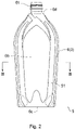
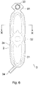
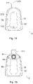
- Figs. 1 to 3 illustrate a sheet material container 5 according to the first embodiment.
- the sheet material container 5 has a container body 6 and an inner container 7 provided in the container body 6.
- the inner container 7 defines an accommodation space 53 for accommodating an inclusion.
- the container body 6 is constituted of a sheet material 3 (container body constituent sheet material 3) in which a plurality of film layers (for example, two film layers including a first film layer 1 and a second film layer 2) are stacked.
- the inner container 7 may be constituted of a sheet material having one film layer, or may be constituted of a sheet material 71 (inner container constituent sheet material 71) in which a plurality of film layers are stacked.
- the container body 6 includes a plurality of planar portions (for example, four planar portions including a first main surface portion 6a, a second main surface portion 6b, a bottom gusset portion 6c, and a top gusset portion 6d).
- the first main surface portion 6a and the second main surface portion 6b are surrounded by an enclosing portion 51 capable of enclosing the filler therein.
- Figs. 1 to 3 illustrate a state after the filler is enclosed in the enclosing portion 51, and the enclosing portion 51 in which the filler is enclosed is three-dimensionally bulged.
- the filler examples include fluids (gas and liquid), solids (for example, powdery/granular materials and resin pellets), and semi-solids (for example, foam materials), and among these fillers, a gas such as air is preferable.
- a spout 61 is attached to the top gusset portion 6d, if necessary.
- the inner container 7 is formed in a bag shape in the container body 6. However, an upper portion of the inner container 7 communicates with an opening portion of the spout 61, and the inclusion can be taken in and out of the accommodation space 53 from the opening portion of the spout 61.
- the inclusion stored in the accommodation space 53 is represented by dots.
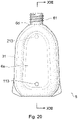
- a container filled with the inclusion can be obtained by attaching a closing cap (not illustrated) to the spout 61. After removing the closing cap and opening the container filled with the inclusion, the inclusion can be poured out by, for example, tilting the container or pressing the first main surface portion 6a and the second main surface portion 6b of the sheet material container 5.
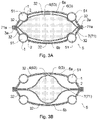
- Fig. 3B illustrates a state where a content of the inclusion 4 is reduced after the inclusion 4 is poured out from a state of Fig. 3A where the container is full of the inclusion 4.
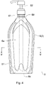
- a cap 62 equipped with a pump may be attached to the spout 61 after the inclusion 4 is placed in the accommodation space 53 of the inner container 7.
- this embodiment is not limited to the case where the spout 61 is attached to the top gusset portion 6d, and for example, a film valve or the like may be provided instead of the spout.
- the type of the inclusion is not limited to a particular inclusion, and may be a liquid (including a pasty inclusion) or a solid (for example, a granulated, granular, or powdery inclusion).
- Specific examples of the inclusions include shampoo, conditioner, body soap, detergent, fabric softener, beverage, and food.
- the container body 6 can be self-supporting with the bottom gusset portion 6c as a grounding portion.
- the container body 6 is not limited to a self-supporting form, and may be a form assuming that the container body 6 is laid down without being self-supporting.
- the sheet material 3 (container body constituent sheet material 3) constituting the container body 6 has a non-joint portion 31 in which an interlayer between the plurality of film layers is not joined, and a joint portion 32 in which the plurality of film layers are joined to each other.
- the filler can be enclosed in the non-joint portion 31. That is, in the present embodiment, the non-joint portion 31 is the enclosing portion 51 capable of enclosing the filler.
- the container body constituent sheet material 3 is constituted of two film layers including the first film layer 1 and the second film layer 2.
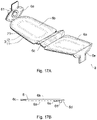
- Fig. 6 is a plan view of the container body constituent sheet material 3 in which the first film layer 1 and the second film layer 2 are stacked, and the container body constituent sheet material 3 is viewed from the second film layer side.
- the sheet material container 5 can be obtained by bending the container body constituent sheet material 3 and joining the peripheral edge portion 3a in a state where the inner container constituent sheet material 71 (not illustrated in Fig. 6 ) is overlaid on the container body constituent sheet material 3 illustrated in Fig. 6 .
- the enclosing portion 51 (the non-joint portion 31 of the container body constituent sheet material 3) of the sheet material container 5 is filled with the filler such as air from an introduction port 34, for example, the introduction port 34 is sealed, whereby the container body 6 (the sheet material container 5) as illustrated in Figs. 1 to 3 in which the filler is filled in the enclosing portion 51 and which is in a self-supporting state is configured.
- the peripheral edge portion 3a is joined by, for example, heat sealing.
- the first film layer 1 constitutes an outer surface of the container body 6.
- the second film layer 2 is stacked inside the first film layer 1.
- the heat sealing includes heat sealing using a heated heat seal bar or a heated roll, and heat sealing using ultrasonic sealing, high frequency sealing, or the like, and refers to all types of heat sealing regardless of the means.
- Fig. 7A is a plan view of the first film layer 1 constituting the container body constituent sheet material 3
- Fig. 7B is a plan view of the second film layer 2 constituting the container body constituent sheet material 3.
- the second film layer 2 is overlaid on the first film layer 1, and an interlayer between the first film layer 1 and the second film layer 2 is joined except for the non-joint portion 31.
- the portion at which the interlayer between the first film layer 1 and the second film layer 2 is joined is the joint portion 32.
- the first film layer 1 and the second film layer 2 are, for example, substantially the same in shape and size in a plan view.
- a hole portion 33 penetrating the first film layer 1 and the second film layer 2 is formed in a portion of the container body constituent sheet material 3 that forms the top gusset portion 6d.
- the spout 61 is inserted into the hole portion 33.
- the spout 61 is illustrated by an alternate long and short dash line, which is a virtual line.
- first film layer 1 and the second film layer 2 is partially subjected to non-joint processing so that the interlayer between the first film layer 1 and the second film layer 2 is partially not joined to form the non-joint portion 31 as illustrated in Fig. 6 .
- an inner surface of the first film layer 1 is subjected to the non-joint processing.
- the portion subjected to the non-joint processing is indicated by innumerable dots.
- first film layer 1 and the second film layer 2 are not joined at the portion subjected to the non-joint processing, and the first film layer 1 and the second film layer 2 are joined at a portion other than the portion subjected to the non-joint processing.
- the first film layer 1 and the second film layer 2 may be joined via an adhesive, or by heat-sealing an innermost layer of the first film layer 1 and an outermost layer of the second film layer 2.
- the innermost layer of the first film layer 1 and the outermost layer of the second film layer 2 are heat-sealed to form the joint portion 32 between the first film layer 1 and the second film layer 2.
- the first film layer has a multilayer film including two or more resin layers.
- an innermost layer of the resin layers constituting the first film layer is referred to as the "first innermost layer”
- an outermost layer of the resin layers constituting the first film layer is referred to as the "first outermost layer”.
- the first film layer is a film layer constituting the outer surface of the container body, the inner surface of the first film layer (inner surface of the first innermost layer) faces the enclosing portion (non-joint portion).
- the first innermost layer is formed of a polyolefin resin layer.
- the polyolefin resin layer is formed of a polyolefin having heat sealability.
- the heat sealability refers to a property of being able to join by heat sealing.
- As the polyolefin resin layer having heat sealability it is preferable to use a polyolefin resin layer without stretching treatment.
- the first film layer has an extruded multilayer structural part having a polyolefin resin layer/an ethylene-vinyl alcohol copolymer resin layer.
- the polyolefin resin layer of the extruded multilayer structural part constitutes the first innermost layer.
- the first film layer is overlaid on the second film layer so that the polyolefin resin layer (first innermost layer) becomes the side facing the non-joint portion.
- the non-joint portion is formed between the film layers, and the filler can be enclosed between the film layers in the non-joint portion. Therefore, in the film layer, the non-joint portion and the enclosing portion can be substantially identified.
- the extruded multilayer structural part refers to a multilayer film structure which has two or more resin layers and in which at least one of the resin layers is stacked on the other resin layer by an extrusion molding method.
- the extruded multilayer structural part refers to a multilayer film structure which has two or more resin layers and in which at least one of the resin layers has a solidified layer of a melt-extruded resin and the resin layer having the solidified layer of the melt-extruded resin is stacked on and bonded to the other resin layer.
- the extruded multilayer structural part includes a case where at least one resin layer without stretching treatment and at least one resin layer subjected to stretching treatment are stacked and bonded, or a case where only two or more resin layers without stretching treatment are stacked and bonded.
- the stretching treatment may be either uniaxial stretching (stretching in an MD direction or a TD direction) or biaxial stretching (stretching in both the MD direction and the TD direction)
- the stretching treatment is preferably the biaxial stretching.
- a coextruded multilayer structural part is conceptually included in the extruded multilayer structural part.
- the coextruded multilayer structural part refers to a multilayer film structure which has two or more resin layers and in which all the resin layers are stacked by an extrusion molding method (co-extrusion molding method). In the film layer formed by the extrusion molding method, adjacent resin layers are stacked on and bonded to each other.
- the coextruded multilayer structural part refers to a coextruded film which has two or more resin layers and in which all the resin layers are each independently having a solidified layer of a melt-extruded resin and in which each resin layer having the solidified layer of the melt-extruded resin is stacked and bonded. From the viewpoint of stretching and non-stretching, the coextruded film preferably has only two or more resin layers without stretching treatment.
- the extruded multilayer structural part of the first film layer has a two-layer structure of a polyolefin resin layer (first innermost layer)/an ethylene-vinyl alcohol copolymer resin layer in order from the side facing the enclosing portion.
- first extruded multilayer structural part the extruded multilayer structural part of the first film layer.
- An interlayer between the polyolefin resin layer and the ethylene-vinyl alcohol copolymer resin layer may be directly stacked and bonded, or the polyolefin resin layer and the ethylene-vinyl alcohol copolymer resin layer may be stacked and bonded with an adhesive resin layer such as adhesive polyolefin interposed therebetween.
- an adhesive resin layer such as adhesive polyolefin interposed therebetween.
- the first extruded multilayer structural part may have three or more layers, provided that it has the two-layer structure.
- Examples of the first extruded structural part include ⁇ 1A> a structure of two kinds of two layers of a polyolefin resin layer (first innermost layer)/an ethylene-vinyl alcohol copolymer resin layer in order from the side facing the enclosing portion, ⁇ 1B> a structure of two kinds of three layers of a polyolefin resin layer (first innermost layer)/an ethylene-vinyl alcohol copolymer resin layer/a polyolefin resin layer in order from the side facing the enclosing portion, ⁇ 1C> a structure of three kinds of four layers of a polyolefin resin layer (first innermost layer)/an ethylene-vinyl alcohol copolymer resin layer/a polyolefin resin layer/a polyester resin layer in order from the side facing the enclosing portion, and ⁇ 1D> a structure of three kinds of three layers of polyolefin resin layer (first innermost layer)/an ethylene-vinyl alcohol copolymer resin
- the adhesive resin layer described above may be interposed between the polyolefin resin layer and the ethylene-vinyl alcohol copolymer resin layer, between the polyolefin resin layer and the polyester resin layer, or/and between the ethylene-vinyl alcohol copolymer resin layer and the polyester resin layer.
- each independently, at least one resin layer may be stacked on another resin layer by extrusion molding, and preferably, all the resin layers (including the adhesive resin layer when the adhesive resin layer is provided) are stacked by coextrusion molding. It is preferable that all the resin layers stacked by the coextrusion molding are not subjected to stretching treatment.
- the first extruded multilayer structural part is preferably ⁇ 1A> or ⁇ 1B>.
- the first extruded multilayer structural part of ⁇ 1A> is preferably a coextruded film in which the polyolefin resin layer and the ethylene-vinyl alcohol copolymer resin layer are each extruded and more preferably a coextruded film in which the polyolefin resin layer, the adhesive resin layer, and the ethylene-vinyl alcohol copolymer resin layer are each extruded.
- the first extruded multilayer structural part of ⁇ 1B> may be a film in which the polyolefin resin layer is extrusion molded onto a coextruded film in which the polyolefin resin layer and the ethylene-vinyl alcohol copolymer resin layer are each extruded or a coextruded film in which the polyolefin resin layer, the ethylene-vinyl alcohol copolymer resin layer, and the polyolefin resin layer are each extrusion molded.
- the first extruded multilayer structural part of ⁇ 1B> is preferably a coextruded film in which the polyolefin resin layer, the ethylene-vinyl alcohol copolymer resin layer, and the polyolefin resin layer are each extruded, and more preferably a coextruded film in which the polyolefin resin layer, the adhesive resin layer, the ethylene-vinyl alcohol copolymer resin layer, the adhesive resin layer, and the polyolefin resin layer are each extruded.
- the first film layer is a resin layer further constituting the first outermost layer (the outermost layer of the first film layer) on the outside of the first extruded multilayer structural part, and it is preferable that a resin layer having heat resistance is stacked.
- the heat-resistant resin layer include a polyester resin layer, a nylon resin layer, and a stretched polyolefin resin layer.
- the polyester resin layer or the stretched polyolefin resin layer is preferably used, and a biaxially stretched polyethylene terephthalate film or a biaxially stretched polyolefin film is more preferably used. Since the stretched polyolefin resin layer such as the stretched polyethylene resin layer is crystallized by orientation, the stretched polyolefin resin layer has heat resistance that can withstand heating during heat sealing as compared with the polyolefin resin layer without stretching treatment.
- a preferred example of the stretched polyolefin resin layer is a stretched polyethylene resin layer.
- examples of polyethylene include high-density polyethylene, medium-density polyethylene, low-density polyethylene, and linear low-density polyethylene.
- the stretched polyethylene resin layer may be uniaxially stretched or biaxially stretched, from the viewpoint of strength, biaxially stretched one is preferable.
- sequential biaxial stretching or simultaneous biaxial stretching can be applied, and after appropriately heating by roll heating, infrared heating, or the other means, stretching can be performed in a desired stretching direction (MD direction, TD direction).
- a stretch ratio is preferably 200% or more and 800% or less, and more preferably 300% or more and 600% or less. By setting a stretch ratio within this range, uneven thickness of the resin layer is unlikely to occur, and breakage during film formation can be prevented.
- the heat-resistant resin layer constituting the first outermost layer may be a single layer or may have a multilayer structure of two or more layers. In the case of two layers, a resin layer in which a biaxially stretched polyethylene terephthalate film and a biaxially stretched nylon film are stacked may be used.
- the heat-resistant resin layer may be one in which an inorganic vapor deposition film such as a metal vapor deposition film or a silica vapor deposition film is stacked.
- a polyester resin layer on which a silica vapor deposition film is stacked (a polyethylene terephthalate film on which the silica vapor deposition film is stacked, preferably a biaxially stretched polyethylene terephthalate film on which the silica vapor deposition film is stacked) is preferably used.
- a biaxially stretched polyethylene terephthalate film and/or a biaxially stretched nylon film is used as an outermost resin layer, the films are usually stacked via an adhesive, as will be described later.
- the heat-resistant resin layer may be stacked on an outer surface of the first extruded multilayer structural part via an adhesive, or may be stacked on the outer surface of the first extruded multilayer structural part by extrusion molding.
- an adhesive for lamination which will be described later, is usually used.
- the heat-resistant resin layer and the outer surface of the first extruded multilayer structural part are directly stacked and bonded, or may be stacked via a binder-like resin layer.
- the heat-resistant resin layer is a polyester resin layer
- adhesiveness to the polyolefin resin layer of the first extruded multilayer structural part may be poor.
- a resin layer serving as a binder for example, a polyethylene resin layer
- a design print layer is provided on the first film layer constituting the outer surface of the container body, if necessary.
- the design print layer may be provided so that the design can be seen from the outside of the container body.
- the design print layer is provided on the outer surface or/and inner surface of the first outermost layer (for example, the resin layer having heat resistance).
- the design print layer is preferably provided on the inner surface of the first outermost layer.
- the design print layer is provided by printing a known color ink on the first outermost layer or the like.
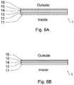
- Fig. 8 illustrates some examples of a layer configuration of the first film layer.
- the first film layer 1 in Fig. 8A has a layer configuration of a polyolefin resin layer 11 (first innermost layer)/an adhesive resin layer/an ethylene-vinyl alcohol copolymer resin layer 12/an adhesive resin layer/a polyolefin resin layer 13/an adhesive layer 14/a design print layer 15/a polyester resin layer 16 (first outermost layer) in order from the side (inside) facing the enclosing portion.
- the adhesive resin layer is not illustrated.
- the first film layer in Fig. 8B has a layer configuration of the polyolefin resin layer 11 (first innermost layer)/an adhesive resin layer/the ethylene-vinyl alcohol copolymer resin layer 12/the adhesive layer 14/the design print layer 15/the polyester resin layer 16 (first outermost layer) in order from the side (inside) facing the enclosing portion.
- the first extruded multilayer structural part having the polyolefin resin layer 11/an adhesive resin layer/the ethylene-vinyl alcohol copolymer resin layer 12/an adhesive resin layer/the polyolefin resin layer 13 in Fig. 8A at least one resin layer is stacked by extrusion molding.
- an adhesive resin and polyolefin are melt-extruded from both sides of the film to be formed in a film shape, whereby the first extruded multilayer structural part is obtained.
- the first extruded multilayer structural part having the polyolefin resin layer 11/an adhesive resin layer/the ethylene-vinyl alcohol copolymer resin layer 12 in Fig. 8B at least one resin layer is stacked by extrusion molding.
- an adhesive resin and polyolefin are melt-extruded from one side of the film to be formed in a film shape, whereby the first extruded multilayer structural part is obtained.
- Each of the first extruded multilayer structural parts of Figs. 8A and 8B is preferably formed by coextrusion molding.
- the first extruded multilayer structural part of Fig. 8A is obtained by melt-extruding the polyolefin, adhesive resin, ethylene-vinyl alcohol copolymer, adhesive resin and polyolefin and forming them in a film shape.
- a thickness of the polyolefin resin layers 11 and 13 of the first extruded multilayer structural part is not limited to a particular thickness, and is, for example, 10 ⁇ m to 150 ⁇ m.
- the polyolefin resin layer 11 constituting the innermost layer of the first film layer 1 is a layer to be heat-sealed, the polyolefin resin layer 11 is preferably relatively thick.
- the thickness of the polyolefin resin layer 11 constituting the first innermost layer is 20 ⁇ m to 150 ⁇ m.
- a thickness of the ethylene-vinyl alcohol copolymer resin layer 12 of the first film layer 1 is not limited to a particular thickness, and is, for example, 4 ⁇ m to 40 ⁇ m.
- a thickness of the adhesive resin layer of the first film layer 1 is not limited to a particular thickness, and is, for example, 3 ⁇ m to 10 ⁇ m.
- the adhesive layer 14 is formed using an adhesive for lamination.
- the adhesive for lamination include a dry laminating adhesive, a solvent-free laminating adhesive, and a wet laminating adhesive.
- the dry laminating adhesive is a solvent-volatile type adhesive containing an organic solvent.
- the solvent-free laminating adhesive is an adhesive that does not contain an organic solvent and does not require a drying step.
- the wet laminating adhesive is a dry type adhesive containing an aqueous solvent.
- a thickness of the adhesive layer 14 is not limited to a particular thickness, and is, for example, 2 ⁇ m to 30 ⁇ m.
- a thickness of the polyester resin layer 16 is not limited to a particular thickness, and is, for example, 8 ⁇ m to 40 ⁇ m.
- the first film layer 1 of Fig. 8 is obtained by applying the adhesive for lamination onto at least one of the first extruded multilayer structural part (extruded multilayer film, preferably coextruded multilayer film) and a polyester resin layer (biaxially stretched polyethylene terephthalate film) and bonding the first extruded multilayer structural part and the polyester resin layer together.
- the polyester resin layer 16 and the first extruded multilayer structural part are stacked and bonded using the adhesive layer 14.
- the resin layer serving as a binder for example, a polyethylene resin layer
- the resin layer may be stacked between the polyester resin layer and the first extruded multilayer structural part to form the first film layer having a polyester resin layer/an extruded binder resin layer/a first extruded multilayer structural part.
- the second film layer has a multilayer film including two or more resin layers.
- an outermost layer of the resin layers constituting the second film layer is referred to as the "second outermost layer”
- an innermost layer of the resin layers constituting the second film layer is referred to as the "second innermost layer”.
- the outer surface of the second film layer (outer surface of the second outermost layer) faces the enclosing portion.
- the second outermost layer is preferably formed of a polyolefin resin layer.
- the polyolefin resin layer is formed of a polyolefin having heat sealability.
- the polyolefin resin layer having heat sealability is preferably a polyolefin resin layer without stretching treatment.
- the second film layer preferably contains an ethylene-vinyl alcohol copolymer resin layer.
- a layer configuration of the preferred second film layer is not limited to a particular layer configuration, provided that the second film layer has a polyolefin resin layer as the second outermost layer and an ethylene-vinyl alcohol copolymer resin layer as a layer other than the second outermost layer.
- the second film layer may have a two-layer structure consisting of only the polyolefin resin layer and the ethylene-vinyl alcohol copolymer resin layer, or may have a multilayer structure having a resin layer in addition to the two layers.
- Examples of the resin layer other than the two layers include another polyolefin resin layer, another polyester resin layer, another nylon resin layer, and the like, which are different from the two layers.
- the second film layer may include an extruded multilayer structural part, or all the resin layers may be stacked and bonded via an adhesive.
- the second film layer preferably has an extruded multilayer structural part including a polyolefin resin layer (second outermost layer)/an ethylene-vinyl alcohol copolymer resin layer.
- the extruded multilayer structural part of the second film layer is referred to as the "second extruded multilayer structural part”.
- An interlayer between the polyolefin resin layer and the ethylene-vinyl alcohol copolymer resin layer may be directly stacked and bonded, or the polyolefin resin layer and the ethylene-vinyl alcohol copolymer resin layer may be stacked and bonded with an adhesive resin layer such as adhesive polyolefin interposed therebetween.
- an adhesive resin layer such as adhesive polyolefin interposed therebetween.
- the second extruded multilayer structural part may have three or more layers, provided that it has the two-layer structure.
- Examples of the second extruded multilayer structural part include ⁇ 2A> a structure of two kinds of two layers of a polyolefin resin layer (second outermost layer)/an ethylene-vinyl alcohol copolymer resin layer in order from the side facing the enclosing portion, ⁇ 2B> a structure of two kinds of three layers of a polyolefin resin layer (second outermost layer)/an ethylene-vinyl alcohol copolymer resin layer/a polyolefin resin layer in order from the side facing the enclosing portion, ⁇ 2C> a structure of three kinds of four layers of polyolefin resin layer (second outermost layer)/an ethylene-vinyl alcohol copolymer resin layer/a polyolefin resin layer/a polyester resin layer in order from the side facing the enclosing portion, and ⁇ 2D> a structure of three kinds of five layers of a polyolefin resin layer (second outermost layer)/a nylon resin layer/an ethylene-viny
- the adhesive resin layer described above may be interposed between the polyolefin resin layer and the ethylene-vinyl alcohol copolymer resin layer, between the polyolefin resin layer and the polyester resin layer, between the polyolefin resin layer and the nylon resin layer, between the nylon resin layer and the ethylene-vinyl alcohol copolymer resin layer, or/and between the nylon resin layer and the polyolefin resin layer.
- each independently, at least one resin layer may be stacked on another resin layer by extrusion molding, and preferably, all the resin layers are stacked by coextrusion molding. It is preferable that all the resin layers stacked by the coextrusion molding are not subjected to stretching treatment.
- the second extruded multilayer structural part is preferably ⁇ 2A> or ⁇ 2B>.
- the second extruded multilayer structural part of ⁇ 2A> is preferably a coextruded film in which the polyolefin resin layer and the ethylene-vinyl alcohol copolymer resin layer are each extrusion molded and more preferably a coextruded film in which the polyolefin resin layer, the adhesive resin layer, and the ethylene-vinyl alcohol copolymer resin layer are each extrusion molded.
- the second extruded multilayer structural part of ⁇ 2B> is preferably a coextruded film in which the polyolefin resin layer, the ethylene-vinyl alcohol copolymer resin layer, and the polyolefin resin layer are each extrusion molded, and more preferably a coextruded film in which the polyolefin resin layer, the adhesive resin layer, the ethylene-vinyl alcohol copolymer resin layer, the adhesive resin layer, and the polyolefin resin layer are each extrusion molded.
- the second film layer is a resin layer further constituting the second innermost layer (the innermost layer of the second film layer) on the inside of the second extruded multilayer structural part, and the resin layer having heat resistance may be stacked.
- the resin layer having excellent heat resistance those as exemplified in the heat-resistant resin layer of the first film layer are used, and examples thereof include a polyester resin layer, a nylon resin layer, and a stretched polyolefin resin layer.
- the polyester resin layer or the stretched polyolefin resin layer is preferably used, and the biaxially stretched polyethylene terephthalate film or the biaxially stretched polyolefin film is more preferably used.
- the heat-resistant resin layer constituting the second innermost layer may be a single layer or may have a multilayer structure of two or more layers.
- the heat-resistant resin layer may be one in which an inorganic vapor deposition film such as a metal vapor deposition film or a silica vapor deposition film is provided.
- the heat-resistant resin layer may be stacked on an inner surface of the second extruded multilayer structural part via an adhesive, or may be stacked on the inner surface of the second extruded multilayer structural part by extrusion molding.
- coextrusion molding may be performed at the same time as the binder-like resin layer (for example, a polyethylene resin layer).
- Fig. 9 illustrates some examples of a layer configuration of the second film layer.
- the second film layer 2 of Fig. 9A has a layer configuration of a polyolefin resin layer 21 (second outermost layer)/an adhesive resin layer/an ethylene-vinyl alcohol copolymer resin layer 22/an adhesive resin layer/a polyolefin resin layer 23 (second innermost layer) in order from the side (outside) facing the enclosing portion.
- the second film layer 2 of Fig. 9B has a layer configuration of the polyolefin resin layer 21 (second outermost layer)/an adhesive resin layer/the ethylene-vinyl alcohol copolymer resin layer 22/an adhesive resin layer/the polyolefin resin layer 23/an adhesive layer 24/a polyester resin layer 26 (second innermost layer) in order from the side (outside) facing the enclosing portion.
- the second film layer 2 of Fig. 9C has a layer configuration of the polyolefin resin layer 21 (second outermost layer)/an adhesive resin layer/a nylon resin layer 27/an adhesive resin layer/the ethylene-vinyl alcohol copolymer resin layer 22/an adhesive resin layer/a nylon resin layer 28/an adhesive resin layer/the polyolefin resin layer 23 (second innermost layer) in order from the side (outside) facing the enclosing portion.
- At least one resin layer is stacked by extrusion molding, and preferably, all the resin layers are stacked by coextrusion molding.
- At least one resin layer is stacked by extrusion molding, and preferably all the resin layers are stacked by coextrusion molding.
- a thickness of the polyolefin resin layers 21 and 23 of the second film layer 2 is not limited to a particular thickness, and is, for example, 10 ⁇ m to 150 ⁇ m.
- the polyolefin resin layer 21 constituting the outermost layer of the second film layer 2 is a layer to be heat-sealed, the polyolefin resin layer 21 is preferably relatively thick.
- the thickness of the polyolefin resin layer 21 constituting the second outermost layer is 20 ⁇ m to 150 ⁇ m.
- a thickness of the ethylene-vinyl alcohol copolymer resin layer 22 of the second film layer 2 is not limited to a particular thickness, and is, for example, 4 ⁇ m to 40 ⁇ m.
- a thickness of the polyester resin layer 26 of the second film layer 2 is not limited to a particular thickness, and is, for example, 8 ⁇ m to 40 ⁇ m.
- a thickness of the nylon resin layers 27 and 28 of the second film layer 2 is not limited to a particular thickness, and is, for example, 8 ⁇ m to 40 ⁇ m.
- a thickness of the adhesive resin layer of the second film layer 2 is not limited to a particular thickness, and is, for example, 3 ⁇ m to 10 ⁇ m.
- the adhesive layer 24 is formed using an adhesive for lamination similarly to the first film layer.
- a thickness of the adhesive layer 24 is not limited to a particular thickness, and is, for example, 2 ⁇ m to 30 ⁇ m.
- a design print layer (not illustrated) may be provided on the second film layer, if necessary.
- the design print layer is provided on the second film layer, it is preferable to provide the design print layer so that the design can be seen from the outside of the container body.
- the design print layer is provided on the second film layer
- the design print layer is provided on the outer surface or/and inner surface of the second innermost layer, or is provided on the outer surface or/and inner surface of the resin layer other than the second innermost layer.
- the polyolefin resin layer of the first film layer and the second film layer is formed of a polyolefin having heat sealability.
- polystyrene resin As the polyolefin having heat sealability, general-purpose polyethylene or polypropylene can be used, preferably low-density polyethylene can be used, and more preferably linear low-density polyethylene can be used.
- the linear low-density polyethylene is a polymer containing at least a structural unit derived from ethylene as a repeating unit.
- the linear low-density polyethylene contains a short-chain branched structure and is generally a low-density polyethylene obtained by copolymerizing ethylene with an ⁇ -olefin at medium or low pressure.
- a density of the linear low-density polyethylene is, for example, about 0.850 to 0.945 g/cm 3 , and preferably about 0.910 to 0.925 g/cm 3 .
- the ethylene-vinyl alcohol copolymer resin layer of the first film layer and the second film layer has an ethylene-vinyl alcohol copolymer.
- the ethylene-vinyl alcohol copolymer has high gas barrier properties.
- the ethylene-vinyl alcohol copolymer is a polymer compound obtained by saponifying an ethylene-vinyl acetate-based copolymer (copolymer containing ethylene and vinyl acetate as essential monomer components).
- An ethylene component content of the ethylene-vinyl alcohol-based copolymer is preferably 20 to 60% by weight based on a total amount of the monomer components.
- a degree of saponification of a vinyl acetate component is preferably 95 mol% or more from the viewpoint of gas barrier properties.
- the polyester resin layer of the first film layer and the second film layer has polyester.
- polyester polyethylene terephthalate (PET) type, poly(ethylene-2,6-naphthalene dicarboxylate) (PEN) type, and the like can be used, and polyethylene terephthalate (PET) type can be preferably used.
- the nylon resin layer of the first film layer and the second film layer has polyamide.
- polyamide polyamide-6, polyamide-12, polyamide-66, polyamide-610, polyamide-11, and the like can be used.
- the enclosing portion is required not to break when the container body 6 is dropped.
- tensile elongation in the MD direction corresponding to the width direction of the sheet material container 5 with respect to the self-supporting state of the sheet material container 5
- the tensile elongations in the MD direction of both the first film layer 1 and the second film layer 2 are kept high.
- the tensile elongation in the MD direction of the extruded multilayer structural part of each of the first film layer 1 and the second film layer 2 is preferably each independently, for example, 300% or more, from the viewpoint of further enhancing the impact resistance, the tensile elongation is more preferably 400% or more, and from the viewpoint of still further enhancing the impact resistance, the tensile elongation is further preferably 500% or more.
- the tensile elongation in the TD direction (corresponding to the height direction of the sheet material container 5 with respect to the self-supporting state of the sheet material container 5) of at least one of the first film layer 1 and the second film layer 2 is also kept high, and it is more preferable that the tensile elongations in the TD direction of both the first film layer 1 and the second film layer 2 are kept high.
- the tensile elongation in the TD direction of the extruded multilayer structural part of each of the first film layer 1 and the second film layer 2 is preferably each independently, for example, 300% or more, from the viewpoint of further enhancing the impact resistance, the tensile elongation is more preferably 400% or more, and from the viewpoint of still further enhancing the impact resistance, the tensile elongation is further preferably 500% or more.
- the upper limit of the tensile elongation in each MD and TD direction is 900% or less, further 800% or less, and 700% or less.
- tensile elongation (%) 100 ⁇ (L-L0)AL0.
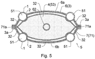
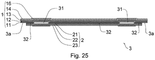
- Fig. 10 is an enlarged end view of the container body constituent sheet material 3 having the first film layer 1 and the second film layer 2 having a preferable layer configuration from the above-exemplified examples. Furthermore, Fig. 10 is an end view obtained by cutting a portion along the line X-X of Fig. 6 .
- the first film layer 1 has the polyolefin resin layer 11/an adhesive resin layer/the ethylene-vinyl alcohol copolymer resin layer 12/an adhesive resin layer/the polyolefin resin layer 13/the adhesive layer 14/a design print layer/the polyester resin layer 16 in order from the side (inside) facing the non-joint portion 31 or the enclosing portion 51.
- the second film layer 2 has the polyolefin resin layer 21/an adhesive resin layer/the ethylene-vinyl alcohol copolymer resin layer 22/an adhesive resin layer/the polyolefin resin layer 23 in order from the side (outside) facing the non-joint portion 31 or the enclosing portion 51.
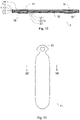
- Fig. 11 is a plan view of the sheet material 71 (inner container constituent sheet material 71) constituting the inner container 7.
- the inner container constituent sheet material 71 is used so as to be overlaid on the inside of the container body constituent sheet material 3 (the innermost layer side of the second film layer 2).
- the hole portion 33 is formed in the portion forming the top gusset portion 6d.
- the inner container constituent sheet material 71 is not limited to a particular material, it is preferable to use a multilayer film having a polyolefin resin layer having heat sealability on both sides, and in addition, it is more preferable to use a multilayer film having a polyolefin resin layer having heat sealability on both sides and including a layer having gas barrier properties.
- the polyolefin resin layer having heat sealability is preferably a polyolefin resin layer without stretching treatment.
- the inner container constituent sheet material 71 has a multilayer film having at least two kinds selected from a polyolefin resin layer, an ethylene-vinyl alcohol copolymer resin layer, and a nylon resin layer.
- the multilayer film constituting the inner container constituent sheet material 71 may be a multilayer film (coextruded film) in which all the resin layers are formed by the extrusion molding method, a multilayer film in which two or more resin layers are formed by the extrusion molding method and some layers are stacked and bonded via an adhesive layer, or a multilayer film in which all layers are stacked and bonded via the adhesive layer.
- Examples of a preferable layer configuration of the inner container constituent sheet material 71 include ⁇ 7A> a polyolefin resin layer having heat sealability/an adhesive resin layer/an ethylene-vinyl alcohol copolymer resin layer/an adhesive resin layer/a polyolefin resin layer having heat sealability, ⁇ 7B> a polyolefin resin layer having heat sealability/an adhesive layer/a polyester resin layer with an inorganic vapor deposition film/an adhesive layer/a polyolefin resin layer having heat sealability, ⁇ 7C> a polyolefin resin layer having heat sealability/an adhesive layer/nylon resin layer with an inorganic vapor deposition film/an adhesive layer/a polyolefin resin layer having heat sealability, ⁇ 7D> a polyolefin resin layer having heat sealability/an adhesive layer or an adhesive resin layer/a nylon resin layer/an adhesive layer/a polyester resin layer with an inorganic vapor deposition film/an adhesive layer/a nylon resin layer/an adhesive layer or an adhesive resin layer
- a polyolefin resin layer having heat sealability/an adhesive layer/a polyester resin layer with an inorganic vapor deposition film/an adhesive layer/a nylon resin layer/an adhesive layer/a polyolefin resin layer having heat sealability is used.
- a metal vapor deposition film such as aluminum, a silica vapor deposition film, or the like can be used.
- Fig. 12A is an enlarged end view of the inner container constituent sheet material 71 having one layer configuration in the above-exemplified examples
- Fig. 12B is an enlarged end view of the inner container constituent sheet material 71 having the other layer configuration in the above-exemplified examples
- Fig. 12 is an end view obtained by cutting a portion along the line XII-XII of Fig. 11 .
- the inner container constituent sheet material 71 has a polyolefin resin layer 711/an adhesive layer/a polyester resin layer 712 with an inorganic vapor deposition film/an adhesive layer/a polyolefin resin layer 713 in order from the side facing the container body constituent sheet material 3 (in order from the outside).
- the inner container constituent sheet material 71 has a polyolefin resin layer 714/an adhesive layer/a polyester resin layer 715 with an inorganic vapor deposition film/an adhesive layer/a nylon resin layer 716/an adhesive layer or an adhesive resin layer/a polyolefin resin layer 717 in order from the side facing the container body constituent sheet material 3 (in order from the outside).
- the adhesive layer (or the adhesive resin layer) is not illustrated.
- a design print layer (not illustrated) may be provided on the inner container constituent sheet material 71, if necessary.
- the design print layer is provided on the inner container constituent sheet material 71, it is preferable to provide the design print layer so that the design can be seen from the outside of the container body.
- the design print layer is provided on the inner container constituent sheet material 71
- the design print layer is provided on the outer surface of the innermost layer of the sheet material 71, or is provided on the outer surface or/and inner surface of the resin layer other than the innermost layer.
- the inner container constituent sheet material 71 illustrated in Fig. 11 is overlaid on an inner surface side of the container body constituent sheet material 3 illustrated in Fig. 6 , the peripheral edge portions 3a and 71a of the container body constituent sheet material 3 and the inner container constituent sheet material 71 are heat-sealed with each other to form a container body constituent sheet material with an inner container constituent sheet material (hereinafter, referred to as the container body sheet material with an inner container).
- the container body sheet material with an inner container By bending the container body sheet material with an inner container and joining (for example, heat-sealing) the peripheral edge portions (the peripheral edge portion 71a of the container body sheet material with an inner container) to each other, the sheet material container 5 including the inner container 7 in the container body 6 is formed.
- the introduction port 34 is sealed, whereby the sheet material container 5 in a state where the filler is filled in the enclosing portion 51 as illustrated in Figs. 1 to 3 is obtained.
- the heat sealing includes heat sealing using a heated heat seal bar or a heated roll, and heat sealing using ultrasonic sealing, high frequency sealing, or the like, and refers to all types of heat sealing regardless of the means.
- Fig. 13 is an enlarged end view of a part of the sheet material container 5 formed using the container body constituent sheet material 3 and the inner container constituent sheet material 7.
- Fig. 13 is also an end view illustrating in detail the layer configuration of the container body constituent sheet material 3 and the inner container constituent sheet material 71 for a part of the sheet material container 5 of Fig. 3 .
- the first film layer 1 has the polyolefin resin layer 11/an adhesive resin layer/the ethylene-vinyl alcohol copolymer resin layer 12/an adhesive resin layer/the polyolefin resin layer 13/the adhesive layer 14/a design print layer/the polyester resin layer 16 in order from the side (inside) facing the non-joint portion 31 or the enclosing portion 51.
- the second film layer 2 has the polyolefin resin layer 21/an adhesive resin layer/the ethylene-vinyl alcohol copolymer resin layer 22/an adhesive resin layer/the polyolefin resin layer 23 in order from the side (outside) facing the non-joint portion 31 or the enclosing portion 51.
- the inner container constituent sheet material 71 has the polyolefin resin layer 711/an adhesive layer/the polyester resin layer 712 with an inorganic vapor deposition film/an adhesive layer/the polyolefin resin layer 713 in order from the side facing the container body constituent sheet material 3 (in order from the outside).
- the adhesive resin layer and the adhesive layer are not illustrated except for the adhesive layer of the first film layer 1 (the same applies to Fig. 26 ).
- the first film layer 1 of the sheet material container 5 of the present invention has the first extruded multilayer structural part having the polyolefin resin layer 11/the ethylene-vinyl alcohol copolymer resin layer 12 on the side facing the enclosing portion 51 (preferably the first extruded multilayer structural part having the polyolefin resin layer 11/the ethylene-vinyl alcohol copolymer resin layer 12/the polyolefin resin layer 13).
- the first film layer 1 is difficult to delaminate.
- the first film layer 1 having the first extruded multilayer structural part by using the first film layer 1 having the first extruded multilayer structural part, delamination of the first film layer 1 is less likely to occur in a region corresponding to the enclosing portion 51 as compared with a conventional sheet material container. Delamination is also less likely to occur in the second film layer 2.
- the sheet material container 5 contains a relatively large amount of polyolefin resin. This is because polyolefin resins such as polyethylene are easy to recycle. From this point of view, it is preferable that the first film layer 1, the second film layer 2 or/and the inner container constituent sheet material 71 (including no polyester resin layer and no nylon resin layer) mainly have a polyolefin resin layer.
- the first film layer 1 constituting the sheet material container 5 has the first extruded multilayer structural part and the stretched polyethylene resin layer stacked on the outside of the first extruded multilayer structural part via an adhesive.
- the first extruded multilayer structural part include ⁇ 1A> to ⁇ 1D> described above, and among them, a coextruded film having a linear low-density polyethylene resin layer having heat sealability/an ethylene-vinyl alcohol copolymer resin layer/a linear low-density polyethylene resin layer having heat sealability is preferable.
- stretched polyethylene resin layer examples include a biaxially stretched linear low-density polyethylene film (biaxially stretched LLDPE film), and a biaxially stretched high-density polyethylene film. If heat resistance to heat sealing can be obtained, a high-density polyethylene resin layer without stretching treatment can be used instead of the stretched polyethylene.
- an adhesive for dry lamination is not used, and, for example, between the first extruded multilayer structural part and the stretched polyethylene resin layer, a polyethylene resin
- LDPE low density polyethylene
- the stretched polyethylene resin layer may be formed by being stacked on the outside of the first extruded multilayer structural part and then stretched together with the first extruded multilayer structural part.
- the second film layer 2 constituting the sheet material container 5 has the second extruded multilayer structural part described above.
- the second extruded multilayer structural part include ⁇ 2A> to ⁇ 2D> described above, and among them, a coextruded film having a linear low-density polyethylene resin layer having heat sealability/an ethylene-vinyl alcohol copolymer resin layer/a linear low-density polyethylene resin layer having heat sealability is preferable.
- the inner container constituent sheet material 71 is preferably a coextruded film having a linear low-density polyethylene resin layer having heat sealability/an ethylene-vinyl alcohol copolymer resin layer/a linear low-density polyethylene resin layer having heat sealability.
- Each stretched polyethylene resin used for the first outermost layer and the second outermost layer, a polyethylene-based resin having heat sealability used for each of the first extruded multilayer structural part and the second extruded multilayer structural part, and a polyethylene-based resin having heat sealability used for the inner container constituent sheet material 71 preferably have the same or similar density, average molecular weight, melting point, and the like, and more preferably have the same average molecular weight.
- Examples thereof include the first film layer in which for the polyethylene resin used for the first outermost layer and the polyethylene resin used for the first extruded multilayer structural part, materials having the same average molecular weight are used, and the stretched polyethylene resin is stacked as the stretched polyethylene resin layer on the outside of the first extruded multilayer structural part.
- the same average molecular weight means that the number average molecular weight and the weight average molecular weight do not have to be completely the same, and are substantially the same including a range of variation in resin production.
- Polyethylene resin can be classified into four types: high-density polyethylene, medium-density polyethylene, low-density polyethylene, and linear low-density polyethylene, according to the density, structure, and the like. It is preferable that each stretched polyethylene resin used for the first outermost layer and the second outermost layer, a polyethylene-based resin having heat sealability used for each of the first extruded multilayer structural part and the second extruded multilayer structural part, and the polyethylene-based resin having heat sealability used for the inner container constituent sheet material 71 belong to the same classification.
- the density of a polyethylene resin as a raw material before each stretched polyethylene resin used for the first outermost layer and the second outermost layer is stretched is the same as the density of the polyethylene-based resin having heat sealability used for each of the first extruded multilayer structural part and the second extruded multilayer structural part and/or the density of the polyethylene-based resin having heat sealability used for the inner container constituent sheet material 71.
- the polyethylene resin in the extruded multilayer structural part and the stretched polyethylene resin layer use a polyethylene resin having the same density as a raw material, and after the stretched polyethylene resin layer is subjected to stretching treatment, the first film layer 1 may be formed by being stacked on the outside of the extruded multilayer structural part.
- the same density means that the density does not have to be completely the same, and is substantially the same including the range of variation in resin production.
- first extruded multilayer structural part As the first extruded multilayer structural part, the second extruded multilayer structural part, and the coextruded film of the inner container constituent sheet, a film that has been coextruded and then subjected to stretching treatment can also be used.
- a film formed by stretching the first extruded multilayer structural part having a polyethylene resin layer (first innermost layer)/an ethylene-vinyl alcohol copolymer resin layer/a polyethylene resin layer can be mentioned.
- the stretched polyethylene resin layer stacked on the outside of the first extruded multilayer structural part via an adhesive may be omitted.
- the first film layer 1 and the like contain an ethylene-vinyl alcohol copolymer resin.
- this resin layer does not adversely affect recycling.
- the portion other than the enclosing portion 51 is the joint portion 32 in the interlayer between the first film layer 1 and the second film layer 2, but the present invention is not limited to this.
- the joint portion 32 having a linear shape may be formed in the interlayer between the first film layer 1 and the second film layer 2, and the enclosing portion 51 may be defined by the joint portion 32.
- Fig. 14A is a plan view of the first film layer 1 constituting a container body constituent sheet material 3 of the present embodiment
- Fig. 14B is a plan view of the second film layer 2 constituting the container body constituent sheet material 3.
- the first film layer 1 and the second film layer 2 are, for example, substantially the same in shape and size in a plan view.
- the first film layer 1 and the second film layer 2 are provided with a pair of extension pieces 111 and 211, respectively, for introducing a filler.
- An inlet 112 for the filler is formed at an end edge between the extension pieces 111 and 211.
- a through hole 113 is formed in a portion of the first film layer 1 that forms a first main surface portion 6a, and an outside air inlet 213 formed of a through hole is formed in a portion of the second film layer 2 that forms the first main surface portion 6a.
- the container body constituent sheet material 3 as illustrated in Fig. 15 is obtained.
- a region partitioned by the linear joint portion 32 is the enclosing portion 51 capable of enclosing the filler.
- a region serving as the enclosing portion 51 of the present embodiment is indicated by innumerable dots.
- the first film layer 1 and the second film layer 2 are joined by, for example, heat sealing.
- the first film layer 1 of the present embodiment also has an extruded multilayer structural part having a polyolefin resin layer/an ethylene-vinyl alcohol copolymer resin layer on the side facing the enclosing portion
- the second film layer 2 has an extruded multilayer structural part having a polyolefin resin layer/an ethylene-vinyl alcohol copolymer resin layer/a polyolefin resin layer on the side facing the enclosing portion.
- an innermost layer of the first film layer 1 has a polyolefin resin layer having heat sealability
- an outermost layer of the second film layer 2 has a polyolefin resin layer having heat sealability
- Fig. 16A is a plan view of an inner container constituent sheet material 71, and a plan view of a container body sheet material 8 with an inner container in which the inner container constituent sheet material 71 is overlaid on and joined to an inner surface of the container body constituent sheet material 3.
- the inner container constituent sheet material 71 has, for example, substantially the same shape and the same size as the second film layer 2 in a plan view. No holes are formed in a plane of the inner container constituent sheet material 71.
- An outer surface of the inner container constituent sheet material 71 illustrated in Fig. 16A is overlaid on the inner surface side of the container body constituent sheet material 3 illustrated in Fig. 15 (on the inner surface side of the second film layer 2), and a peripheral edge portion of the container body constituent sheet material 3 and a peripheral edge portion of the inner container constituent sheet material 71 are joined, whereby the container body sheet material 8 with an inner container illustrated in Fig. 16B can be obtained. It is preferable that when the inner container constituent sheet material 71 is joined, a peripheral edge portion of the first film layer 1 and a peripheral edge portion of the second film layer 2 of the container body constituent sheet material 3 are also joined at the same time. In Fig. 6B, the portion (peripheral edge portion) at which the inner container constituent sheet material 71 is joined is shaded.
- the container body constituent sheet material 3 and the inner container constituent sheet material 71 are joined by, for example, heat sealing.
- a hole portion 33 for attaching a spout 61 is formed in a portion of the container body sheet material 8 with an inner container that forms the top gusset portion 6d.
- the hole portion 33 is a through hole that penetrates the first film layer 1, the second film layer 2, and the inner container constituent sheet material 71.
- the container body sheet material 8 with an inner container is bent as illustrated in Fig. 17A .
- a portion forming a bottom gusset portion 6c is bent inward in a mountain shape
- a portion forming the top gusset portion 6d is bent toward an inner surface of a portion forming a second main surface portion 6b
- a portion 6e corresponding to about half of the top gusset portion 6d of a portion forming a first main surface portion 6a is bent toward the outer surface side.
- the container body sheet material 8 with an inner container is flatten so that an inner surface of the container body sheet material 8 with an inner container comes into contact in side view, and the peripheral edge portion (inner surface of the peripheral edge portion of the container body sheet material 8 with an inner container) is joined, whereby a sheet material container 5 as illustrated in Figs. 18 and 19 can be obtained.
- the sheet material container 5 of the present embodiment also includes a container body 6 formed of the sheet material 3 including the first film layer 1 and the second film layer 2, and an inner container 7, and an enclosing portion 31 capable of enclosing a filler is formed in an interlayer between the first film layer 1 and the second film layer 2.
- the first film layer 1 and the second film layer 2 formed in advance in a predetermined shape are joined to form the container body constituent sheet material 3
- the inner container constituent sheet material 71 formed in advance in a predetermined shape is joined to form the container body sheet material 8 with an inner container
- the container body sheet material 8 with an inner container is appropriately bent to join the peripheral edge portion, and thus to prepare the sheet material container 5.
- the production of the sheet material container 5 is not limited to this procedure.
- sheet-like first and second film layers are overlaid on and joined to one another (joined at a portion similar to the joint portion 32 forming the enclosing portion 31), and a sheet-like inner container constituent sheet material is overlaid thereon and joined thereto (joined at portions similar to the peripheral edge portion of the container body constituent sheet material 3 and the peripheral edge portion of the inner container constituent sheet material 71).
- the filler is introduced into the enclosing portion 51 from the introduction port 112 of the sheet material container 5, and the extension piece 111 for introducing a filler is removed while being sealed, whereby as illustrated in Figs. 20 and 21 , the enclosing portion 51 is filled with the filler, and the self-supportable sheet material container 5 can be obtained.
- a cap such as a cap with a pump is attached to the spout 61.
- the cap is not illustrated in Figs. 20 to 22 .
- the inclusion 4 stored in the accommodation space 53 is represented by dots.
- the through hole 113 and the outside air inlet 213 having a through hole are formed in a portion other than the enclosing portion 51 (for example, the first main surface portion 6a).
- the through hole 113 and the outside air inlet 213 are arranged in an in-plane portion of the first film layer 1 and the second film layer 2 surrounded by the enclosing portion 51.
- a space between the first film layer 1 and the second film layer 2 in the portion surrounded by the enclosing portion 51 is not joined, the inner container 7 and the container body 6 (second film layer 2) are not joined, and gaps 6f and 7f (see Fig. 21 ) are formed, respectively.
- the gaps 6f and 7f communicate with the outside through the through hole 113 and the outside air inlet 213.
- a volume of the inner container 7 decreases as illustrated in Fig. 22 . Since external air flows in and out of the gap 7f through the through hole 113 and the outside air inlet 213 (air flow is indicated by arrows), even if the inner container 7 becomes smaller as the inclusion 4 decreases, an outer shape of the container body 6 is hard to collapse. Thus, the sheet material container 5 is self-supporting in a good state even if the inclusion 4 decreases.
- the first film layer 1 and the second film layer 2 are formed to have substantially the same shape and the same size in a plan view.
- the second film layer 2 may be formed slightly smaller than the first film layer 1 in a plan view.
- the portion subjected to the non-joint processing is indicated by innumerable dots.
- Figs. 24 and 25 illustrate the container body constituent sheet material 3 in which the first film layer 1 and the second film layer 2 having the same shape are stacked. Since the second film layer 2 is slightly smaller than the first film layer 1 in a plan view, an inner surface of the first film layer 1 is exposed at a peripheral edge portion 3a of the container body constituent sheet material 3.
- an inner container constituent sheet material 71 illustrated in Fig. 11 is overlaid on an inner surface side of the container body constituent sheet material 3 illustrated in Fig. 24 , and the peripheral edge portions 3a (exposed inner surface of the first film layer 1) of the container body constituent sheet material 3 and a peripheral edge portion 71a of the inner container constituent sheet material 71 are joined by heat sealing or the like to form a container body constituent sheet material with an inner container.
- the container body constituent sheet material with an inner container is bent inward, and while the peripheral edge portions are joined to each other, a non-joint portion 31 is filled with a filler and sealed, whereby a sheet material container 5 including an inner container 7 in a container body 6 as illustrated in Fig. 26 is formed.
- the sheet material container 5 of this modification is different from the sheet-like container of the above embodiment in that the second film layer 2 is not interposed at the peripheral edge portion 3a, and the remaining configuration is the same.
- the sheet material container including the container body and the inner container has been described.
- the sheet material container having no inner container may be used.
- Such other embodiments include the following aspects.
- a sheet material container including a container body that defines an accommodation space for accommodating an inclusion, in which the container body is formed of a sheet material including a first film layer and a second film layer disposed inside the first film layer, the sheet material of the container body has a joint portion at which an interlayer between the first film layer and the second film layer is joined and an enclosing portion in which a filler can be enclosed in the interlayer between the first film layer and the second film layer, and the first film layer has an extruded multilayer structural part having a polyolefin resin layer/an ethylene-vinyl alcohol copolymer resin layer on a side facing the enclosing portion.
- the extruded multilayer structural part of the first film layer has a polyolefin resin layer/an ethylene-vinyl alcohol copolymer resin layer/a polyolefin resin layer.
- the extruded multilayer structural part of the first film layer is formed by coextrusion.
- the second film layer has an extruded multilayer structural part having a polyolefin resin layer/an ethylene-vinyl alcohol copolymer resin layer/a polyolefin resin layer on the side facing the enclosing portion.
- the polyolefin resin layer of the second film layer is a linear low-density polyethylene resin layer.
- the polyolefin resin layer of the first film layer is a linear low-density polyethylene resin layer.
- the first film layer has the extruded multilayer structural part and a polyester resin layer stacked on an outside of the extruded multilayer structural part, and the polyester resin layer constitutes an outer surface of the container body.
- the first film layer has the extruded multilayer structural part and a stretched polyethylene resin layer stacked on an outside of the extruded multilayer structural part, and the stretched polyethylene resin layer constitutes an outer surface of the container body.
- the stretched polyethylene resin layer is formed by biaxial stretching.
- a polyolefin resin layer of the first film layer is a polyethylene resin layer, and an average molecular weight of a polyethylene resin used for the polyethylene resin layer and an average molecular weight of a polyethylene resin used for the stretched polyethylene resin layer are the same.
- the stretched polyethylene resin layer is formed by being stacked on the outside of the extruded multilayer structural part and then stretched.
- the first film layer is formed by melt-extruding a polyethylene resin between the extruded multilayer structural part and the stretched polyethylene resin layer.
- a tensile elongation in an MD direction or/and a TD direction of the extruded multilayer structural part of the first film layer is 300% or more, preferably 400% or more, and more preferably 500% or more.
- a tensile elongation in an MD direction or/and a TD direction of the extruded multilayer structural part of the first film layer is 900% or less, preferably 800% or less, and more preferably 700% or less.
- a tensile elongation in an MD direction or/and a TD direction of the extruded multilayer structural part of the second film layer is 300% or more, preferably 400% or more, and more preferably 500% or more.
- a tensile elongation in an MD direction or/and a TD direction of the extruded multilayer structural part of the second film layer is 900% or less, preferably 800% or less, and more preferably 700% or less.
- the filler is enclosed in the enclosing portion.
- a sheet material container including a container body that defines an accommodation space for accommodating an inclusion, in which the container body is formed of a sheet material including a first film layer and a second film layer disposed inside the first film layer, the sheet material of the container body has a joint portion at which an interlayer between the first film layer and the second film layer is joined and an enclosing portion in which a filler can be enclosed in the interlayer between the first film layer and the second film layer, the first film layer has an extruded multilayer structural part having a polyolefin resin layer/an ethylene-vinyl alcohol copolymer resin layer/a polyolefin resin layer on a side facing the enclosing portion, the polyolefin resin layer is a stretched polyethylene resin layer, and the stretched polyethylene resin layer is formed by stretching the extruded multilayer structural part after the extruded multilayer structural part is formed.
- the filler is enclosed in the enclosing portion.
- the aspect 18 or 19 includes an inner container that is an inner container covered by the container body and defines an accommodation space.
- a sheet material container including a container body that defines an accommodation space for accommodating an inclusion, in which the container body is formed of a sheet material including a first film layer and a second film layer disposed inside the first film layer, the sheet material of the container body has a joint portion at which an interlayer between the first film layer and the second film layer is joined and an enclosing portion in which a filler can be enclosed in the interlayer between the first film layer and the second film layer, the first film layer has an extruded multilayer structural part having a polyolefin resin layer/an ethylene-vinyl alcohol copolymer resin layer/a polyolefin resin layer on a side facing the enclosing portion, and has a stretched polyethylene resin layer stacked on the outside of the extruded multilayer structural part, the polyolefin resin layer is a polyethylene resin layer, a density of a polyethylene resin as a raw material before the stretched polyethylene resin layer is stretched is the same as a density of the polyethylene resin layer of the extru
- the filler is enclosed in the enclosing portion.
- an inner container that is covered by the container body and defines an accommodation space is included.
- LLDPE linear low-density polyethylene resin
- LDPE low-density polyethylene resin
- EVOH ethylene-vinyl alcohol copolymer resin
- Ny nylon resin
- PET polyethylene terephthalate resin
- AD adhesive resin
- Dry dry laminate adhesive
- a coextruded film of an LLDPE layer having a thickness of 30 ⁇ m/an AD layer having a thickness of 4 ⁇ m/an EVOH layer having a thickness of 10 ⁇ m/an AD layer having a thickness of 4 ⁇ m/an LLDPE layer having a thickness of 100 ⁇ m in order from the outside was provided.
- a coextruded film of an LLDPE layer having a thickness of 100 ⁇ m/an AD layer having a thickness of 4 ⁇ m/an EVOH layer having a thickness of 10 ⁇ m/an AD layer having a thickness of 4 ⁇ m/an LLDPE layer having a thickness of 30 ⁇ m in order from the outside was provided.
- a heating bar was pressed against a portion other than the non-joint portion from the outer surface of the first film layer and the inner surface of the second film layer to heat the portion, whereby a container body constituent sheet material in which the non-joint portion and the joint portion were formed in the interlayer between the first film layer and the second film layer as illustrated in Fig. 6 was prepared.
- a container body constituent sheet material was prepared in the same manner as in Example 1, except that a coextruded film of an LLDPE layer having a thickness of 30 ⁇ m/an AD layer having a thickness of 4 ⁇ m/an EVOH layer having a thickness of 10 ⁇ m/an AD layer having a thickness of 4 ⁇ m/an LLDPE layer having a thickness of 40 ⁇ m in order from the outside was used as the first film layer, and a coextruded film of an LLDPE layer having a thickness of 40 ⁇ m/an AD layer having a thickness of 4 ⁇ m/an EVOH layer having a thickness of 10 ⁇ m/an AD layer having a thickness of 4 ⁇ m/an LLDPE layer having a thickness of 30 ⁇ m in order from the outside was used as the second film layer.
- a container body constituent sheet material was prepared in the same manner as in Example 1, except that a coextruded film of an LLDPE layer having a thickness of 25 ⁇ m/an AD layer having a thickness of 4 ⁇ m/an Ny layer having a thickness of 7.5 ⁇ m/an AD layer having a thickness of 4 ⁇ m/an EVOH layer having a thickness of 10 ⁇ m/an AD layer having a thickness of 4 ⁇ m/an Ny layer having a thickness of 7.5 ⁇ m/an AD layer having a thickness of 4 ⁇ m/an LLDPE layer having a thickness of 50 ⁇ m in order from the outside was used as the second film layer.
- a container body constituent sheet material was prepared in the same manner as in Example 1, except that a coextruded film of an LLDPE layer having a thickness of 18 ⁇ m/an AD layer having a thickness of 4 ⁇ m/an EVOH layer having a thickness of 6 ⁇ m/an AD layer having a thickness of 4 ⁇ m/an LLDPE layer having a thickness of 18 ⁇ m in order from the outside was used as the first film layer, and a coextruded film of an LLDPE layer having a thickness of 18 ⁇ m/an AD layer having a thickness of 4 ⁇ m/an EVOH layer having a thickness of 6 ⁇ m/an AD layer having a thickness of 4 ⁇ m/an LLDPE layer having a thickness of 18 ⁇ m in order from the outside was used as the second film layer.
- a container body constituent sheet material was prepared in the same manner as in Example 1, except that a coextruded film of an LLDPE layer having a thickness of 25 ⁇ m/an AD layer having a thickness of 4 ⁇ m/an Ny layer having a thickness of 7.5 ⁇ m/an AD layer having a thickness of 4 ⁇ m/an EVOH layer having a thickness of 10 ⁇ m/an AD layer having a thickness of 4 ⁇ m/an Ny layer having a thickness of 7.5 ⁇ m/an AD layer having a thickness of 4 ⁇ m/an LLDPE layer having a thickness of 50 ⁇ m in order from the outside was used as the first film layer, and a coextruded film of an LLDPE layer having a thickness of 25 ⁇ m/an AD layer having a thickness of 4 ⁇ m/an Ny layer having a thickness of 7.5 ⁇ m/an AD layer having a thickness of 4 ⁇ m/an EVOH layer having a thickness of 10 ⁇ m/an AD layer having a thickness of 4
- a container body constituent sheet material was prepared in the same manner as in Example 1, except that a laminate film of an LLDPE layer having a thickness of 25 ⁇ m/a Dry layer/a transparent vapor-deposited biaxially stretched Ny layer having a thickness of 15 ⁇ m/a Dry layer/an LLDPE layer having a thickness of 40 ⁇ m in order from the outside was used as the first film layer, and a laminate film of an LLDPE layer having a thickness of 40 ⁇ m/a Dry layer/a transparent vapor-deposited biaxially stretched Ny layer having a thickness of 15 ⁇ m/a Dry layer/an LLDPE layer having a thickness of 25 ⁇ m in order from the outside was used as the second film layer.
- a container body constituent sheet material was prepared in the same manner as in Example 1, except that a laminate film of an LLDPE layer having a thickness of 25 ⁇ m/a Dry layer/a transparent vapor-deposited biaxially stretched Ny layer having a thickness of 15 ⁇ m/a Dry layer/an LLDPE layer having a thickness of 30 ⁇ m in order from the outside was used as the first film layer, and a laminate film of an LLDPE layer having a thickness of 30 ⁇ m/a Dry layer/a transparent vapor-deposited biaxially stretched Ny layer having a thickness of 15 ⁇ m/a Dry layer/an LLDPE layer having a thickness of 25 ⁇ m in order from the outside was used as the second film layer.
- a container body constituent sheet material was prepared in the same manner as in Example 1, except that a laminate film of an LLDPE layer having a thickness of 25 ⁇ m/a Dry layer/a transparent vapor-deposited biaxially stretched PET layer having a thickness of 12 ⁇ m/a Dry layer/an LLDPE layer having a thickness of 30 ⁇ m in order from the outside was used as the first film layer, and a laminate film of an LLDPE layer having a thickness of 30 ⁇ m/a Dry layer/a transparent vapor-deposited biaxially stretched PET layer having a thickness of 12 ⁇ m/a Dry layer/an LLDPE layer having a thickness of 25 ⁇ m in order from the outside was used as the second film layer.
- a container body constituent sheet material was prepared in the same manner as in Example 1, except that a laminate film of an LLDPE layer having a thickness of 20 ⁇ m/a Dry layer/a biaxially stretched EVOH layer having a thickness of 12 ⁇ m/a Dry layer/an LLDPE layer having a thickness of 25 ⁇ m in order from the outside was used as the first film layer, and a laminate film of an LLDPE layer having a thickness of 25 ⁇ m/a Dry layer/a biaxially stretched EVOH layer having a thickness of 12 ⁇ m/a Dry layer/an LLDPE layer having a thickness of 20 ⁇ m in order from the outside was used as the second film layer.
- Air was introduced (air pressure 40 kPa) as a filler into the enclosing portion (non-joint portion) from an inlet of the container body constituent sheet material of Examples 1 to 4 and Comparative Examples 1 to 5, and the inlet was heat-sealed in that state and closed (that is, an enclosing portion with an internal pressure of 40 kPa was formed).
- air pressure 40 kPa air pressure 40 kPa
- Blanks in Table 1 mean that the test has not been performed at that temperature and humidity.
- Sheet material Layer configuration 40 kPa 60 kPa 40°C, 75% RH 50°C, 20% RH 40°C, 75% RH 50°C, 20% RH
- Example 1 First film layer LLDPE 30 ⁇ m/AD 4 ⁇ m/EVOH 10 ⁇ m/AD 4 ⁇ m/LLDPE 100 ⁇ m Good Good Good Good Second film layer LLDPE 100 ⁇ m/AD 4 ⁇ m/EVOH 10 ⁇ m/AD 4 ⁇ m/LLDPE 30 ⁇ m
- Example 2 First film layer LLDPE 30 ⁇ m/AD 4 ⁇ m/EVOH 10 ⁇ m/AD 4 ⁇ m/LLDPE 40 ⁇ m Good Good Good Good Good Second film layer LLDPE 40 ⁇ m/AD 4 ⁇ m/EVOH 10 ⁇ m/AD 4 ⁇ m/LLDPE 30 ⁇ m
- Example 3 First film layer LLDPE 30 ⁇ m/AD 4 ⁇ m/EVOH 10
- a container body constituent sheet material was prepared in the same manner as in Example 1, except that a film of a biaxially stretched PET layer having a thickness of 12 ⁇ m/a Dry layer/an LLDPE layer having a thickness of 30 ⁇ m/an AD layer having a thickness of 4 ⁇ m/an EVOH layer having a thickness of 10 ⁇ m/an AD layer having a thickness of 4 ⁇ m/an LLDPE layer having a thickness of 100 ⁇ m in order from the outside was used as the first film layer, and a film of an LLDPE layer having a thickness of 100 ⁇ m/an AD layer having a thickness of 4 ⁇ m/an EVOH layer having a thickness of 10 ⁇ m/an AD layer having a thickness of 4 ⁇ m/an LLDPE layer having a thickness of 30 ⁇ m/a Dry layer/a biaxially stretched PET layer having a thickness of 12 ⁇ m in order from the outside was used as the second film layer.
- a coextruded film was used for the LLDPE layer/the AD layer/the EVOH layer/the AD layer/the LLDPE layer of the first film layer and the second film layer.
- the first film layer and the second film layer were prepared by laminating a biaxially stretched PET film on the coextruded film via a dry laminate adhesive (Dry).
- a container body constituent sheet material was prepared in the same manner as in Example 1, except that a film of a biaxially stretched PET layer having a thickness of 12 ⁇ m/an LDPE layer having a thickness of 15 ⁇ m/an LLDPE layer having a thickness of 30 ⁇ m/an AD layer having a thickness of 4 ⁇ m/an EVOH layer having a thickness of 10 ⁇ m/an AD layer having a thickness of 4 ⁇ m/an LLDPE layer having a thickness of 100 ⁇ m in order from the outside was used as the first film layer, and a film of an LLDPE layer having a thickness of 100 ⁇ m/an AD layer having a thickness of 4 ⁇ m/an EVOH layer having a thickness of 10 ⁇ m/an AD layer having a thickness of 4 ⁇ m/an LLDPE layer having a thickness of 30 ⁇ m/an LDPE layer having a thickness of 15 ⁇ m/a biaxially stretched PET layer having a thickness of 12 ⁇ m in order from the outside was used as the
- the first film layer and the second film layer were each an extruded film formed by melt-extruding LDPE with a thickness of 15 ⁇ m between a coextruded film of an LLDPE layer having a thickness of 30 ⁇ m/an AD layer having a thickness of 4 ⁇ m/an EVOH layer having a thickness of 10 ⁇ m/an AD layer having a thickness of 4 ⁇ m/an LLDPE layer having a thickness of 100 ⁇ m and a biaxially stretched PET film having a thickness of 12 ⁇ m.
- An anchor coat layer was provided in advance on one side (melt extruded surface of LDPE) of the biaxially stretched PET film.
- a container body constituent sheet material was prepared in the same manner as in Example 1, except that a film of a biaxially stretched PET layer having a thickness of 12 ⁇ m/a Dry layer/an LLDPE layer having a thickness of 25 ⁇ m/an AD layer having a thickness of 4 ⁇ m/an Ny layer having a thickness of 7.5 ⁇ m/an AD layer having a thickness of 4 ⁇ m/an EVOH layer having a thickness of 10 ⁇ m/an AD layer having a thickness of 4 ⁇ m/an Ny layer having a thickness of 7.5 ⁇ m/an AD layer having a thickness of 4 ⁇ m/an LLDPE layer having a thickness of 50 ⁇ m in order from the outside was used as the first film layer, and a film of LLDPE layer having a thickness of 50 ⁇ m/an AD layer having a thickness of 4 ⁇ m/an Ny layer having a thickness of 7.5 ⁇ m/an AD layer having a thickness of 4 ⁇ m/an EVOH layer having a thickness of 10 ⁇ m
- a coextruded film was used for the LLDPE layer/the AD layer/the Ny layer/the AD layer/the EVOH layer/the AD layer/the Ny layer/the AD layer/the LLDPE layer of the first film layer and the second film layer.
- the first film layer and the second film layer were prepared by laminating a biaxially stretched PET film on the coextruded film via a dry laminate adhesive (Dry).
- a container body constituent sheet material was prepared in the same manner as in Example 1, except that a film of a biaxially stretched PET layer having a thickness of 12 ⁇ m/an LDPE layer having a thickness of 15 ⁇ m/an LLDPE layer having a thickness of 25 ⁇ m/an AD layer having a thickness of 4 ⁇ m/an Ny layer having a thickness of 7.5 ⁇ m/an AD layer having a thickness of 4 ⁇ m/an EVOH layer having a thickness of 10 ⁇ m/an AD layer having a thickness of 4 ⁇ m/an Ny layer having a thickness of 7.5 ⁇ m/an AD layer having a thickness of 4 ⁇ m/an LLDPE layer having a thickness of 50 ⁇ m in order from the outside was used as the first film layer, and a film of an LLDPE layer having a thickness of 50 ⁇ m/an AD layer having a thickness of 4 ⁇ m/an EVOH layer having a thickness of 10 ⁇ m/an AD layer having a thickness of 4 ⁇ m/an
- This film was an extruded film formed by melt-extruding LDPE with a thickness of 15 ⁇ m between a coextruded film of an LLDPE layer having a thickness of 25 ⁇ m/an AD layer having a thickness of 4 ⁇ m/an Ny layer having a thickness of 7.5 ⁇ m/an AD layer having a thickness of 4 ⁇ m/an EVOH layer having a thickness of 10 ⁇ m/an AD layer having a thickness of 4 ⁇ m/an Ny layer having a thickness of 7.5 ⁇ m/an AD layer having a thickness of 4 ⁇ m/an LLDPE layer having a thickness of 50 ⁇ m and a biaxially stretched PET film having a thickness of 12 ⁇ m.
- An anchor coat layer was provided in advance on one side (melt extruded surface of LDPE) of the biaxially stretched PET film.
- a container body constituent sheet material was prepared in the same manner as in Example 1, except that a laminate film of a biaxially stretched PET layer having a thickness of 12 ⁇ m/a Dry layer/a transparent vapor-deposited biaxially stretched PET layer having a thickness of 12 ⁇ m/a Dry layer/a biaxially stretched Ny layer having a thickness of 15 ⁇ m/a Dry layer/an LLDPE layer having a thickness of 50 ⁇ m in order from the outside was used as the first film layer, and a laminate film of an LLDPE layer having a thickness of 50 ⁇ m/a Dry layer/a biaxially stretched Ny layer having a thickness of 15 ⁇ m/a Dry layer/a transparent vapor-deposited biaxially stretched PET layer having a thickness of 12 ⁇ m/a Dry layer/a biaxially stretched PET layer having a thickness of 12 ⁇ m in order from the outside was used as the second film layer.
- a container body constituent sheet material was prepared in the same manner as in Example 1, except that a laminate film of a transparent vapor-deposited biaxially stretched PET layer having a thickness of 12 ⁇ m/a Dry layer/a biaxially stretched Ny layer having a thickness of 15 ⁇ m/a Dry layer/an LLDPE layer having a thickness of 30 ⁇ m in order from the outside was used as the first film layer, and a laminate film of an LLDPE layer having a thickness of 30 ⁇ m/a Dry layer/a biaxially stretched Ny layer having a thickness of 15 ⁇ m/a Dry layer/a transparent vapor-deposited biaxially stretched PET layer having a thickness of 12 ⁇ m in order from the outside was used as the second film layer.
- a container body constituent sheet material was prepared in the same manner as in Example 1, except that a laminate film of a transparent vapor-deposited biaxially stretched Ny layer having a thickness of 15 ⁇ m/a Dry layer/an LLDPE layer having a thickness of 20 ⁇ m in order from the outside was used as the first film layer, and a laminate film of an LLDPE layer having a thickness of 20 ⁇ m/a Dry layer/a transparent vapor-deposited biaxially stretched Ny layer having a thickness of 15 ⁇ m in order from the outside was used as the second film layer.
- a container body constituent sheet material was prepared in the same manner as in Example 1, except that a film of a biaxially stretched PET layer having a thickness of 12 ⁇ m/a Dry layer/an LLDPE layer having a thickness of 30 ⁇ m/an AD layer having a thickness of 4 ⁇ m/an EVOH layer having a thickness of 10 ⁇ m/an AD layer having a thickness of 4 ⁇ m/an LLDPE layer having a thickness of 100 ⁇ m in order from the outside was used as the first film layer, and a film of an LLDPE layer having a thickness of 100 ⁇ m/an AD layer having a thickness of 4 ⁇ m/an EVOH layer having a thickness of 10 ⁇ m/an AD layer having a thickness of 4 ⁇ m/an LLDPE layer having a thickness of 30 ⁇ m/a Dry layer/a biaxially stretched PET layer having a thickness of 12 ⁇ m in order from the outside was used as the second film layer.
- a coextruded film was used for the LLDPE layer/
- a container body constituent sheet material was prepared in the same manner as in Example 1, except that a film of a biaxially stretched PET layer having a thickness of 12 ⁇ m/an LDPE layer having a thickness of 15 ⁇ m/an LLDPE layer having a thickness of 30 ⁇ m/an AD layer having a thickness of 4 ⁇ m/an EVOH layer having a thickness of 10 ⁇ m/an AD layer having a thickness of 4 ⁇ m/an LLDPE layer having a thickness of 100 ⁇ m in order from the outside was used as the first film layer, and a film of an LLDPE layer having a thickness of 100 ⁇ m/an AD layer having a thickness of 4 ⁇ m/an EVOH layer having a thickness of 10 ⁇ m/an AD layer having a thickness of 4 ⁇ m/an LLDPE layer having a thickness of 30 ⁇ m/an LDPE layer having a thickness of 15 ⁇ m/a biaxially stretched PET layer having a thickness of 12 ⁇ m in order from the outside was used as the
- This film was an extruded film formed by melt-extruding LDPE with a thickness of 15 ⁇ m between a coextruded film of an LLDPE layer having a thickness of 30 ⁇ m/an AD layer having a thickness of 4 ⁇ m/an EVOH layer having a thickness of 10 ⁇ m/an AD layer having a thickness of 4 ⁇ m/an LLDPE layer having a thickness of 100 ⁇ m and a biaxially stretched PET film having a thickness of 12 ⁇ m.
- An anchor coat layer was provided in advance on one side (melt extruded surface of LDPE) of the biaxially stretched PET film.
- a container body constituent sheet material was prepared in the same manner as in Example 1, except that a coextruded film of an LLDPE layer having a thickness of 18 ⁇ m/an AD layer having a thickness of 4 ⁇ m/an EVOH layer having a thickness of 6 ⁇ m/an AD layer having a thickness of 4 ⁇ m/an LLDPE layer having a thickness of 18 ⁇ m in order from the outside was used as the first film layer, and a coextruded film of an LLDPE layer having a thickness of 18 ⁇ m/an AD layer having a thickness of 4 ⁇ m/an EVOH layer having a thickness of 6 ⁇ m/an AD layer having a thickness of 4 ⁇ m/an LLDPE layer having a thickness of 18 ⁇ m in order from the outside was used as the second film layer.
- a container body constituent sheet material was prepared in the same manner as in Example 1, except that a film of a transparent vapor-deposited biaxially stretched PET layer having a thickness of 12 ⁇ m/a Dry layer/an LLDPE layer having a thickness of 18 ⁇ m/an AD layer having a thickness of 4 ⁇ m/an EVOH layer having a thickness of 6 ⁇ m/an AD layer having a thickness of 4 ⁇ m/an LLDPE layer having a thickness of 18 ⁇ m in order from the outside was used as the first film layer, and a coextruded film of an LLDPE layer having a thickness of 18 ⁇ m/an AD layer having a thickness of 4 ⁇ m/an EVOH layer having a thickness of 6 ⁇ m/an AD layer having a thickness of 4 ⁇ m/an LLDPE layer having a thickness of 18 ⁇ m in order from the outside was used as the second film layer.
- a coextruded film was used for the LLDPE layer/the AD layer/the EVOH layer/the AD layer/the LLDPE layer of the first film layer.
- the first film layer was prepared by laminating a transparent vapor-deposited biaxially stretched PET film on the coextruded film via a dry laminate adhesive (Dry).
- a container body constituent sheet material was prepared in the same manner as in Example 1, except that a film of a biaxially stretched LLDPE layer having a thickness of 40 ⁇ m/an LDPE layer having a thickness of 15 ⁇ m/an LLDPE layer having a thickness of 18 ⁇ m/an AD layer having a thickness of 4 ⁇ m/an EVOH layer having a thickness of 6 ⁇ m/an AD layer having a thickness of 4 ⁇ m/an LLDPE layer having a thickness of 18 ⁇ m in order from the outside was used as the first film layer, and a coextruded film of an LLDPE layer having a thickness of 18 ⁇ m/an AD layer having a thickness of 4 ⁇ m/an EVOH layer having a thickness of 6 ⁇ m/an AD layer having a thickness of 4 ⁇ m/an LLDPE layer having a thickness of 18 ⁇ m in order from the outside was used as the second film layer.
- the first film layer used in Example 11 is an extruded film formed by using a biaxially stretched LLDPE layer (biaxially stretched LLDPE film) having a thickness of 40 ⁇ m instead of the transparent vapor-deposited biaxially stretched PET layer (transparent vapor-deposited biaxially stretched PET film) having a thickness of 12 ⁇ m of the first film layer of Example 10 and melt-extruding LDPE with a thickness of 15 ⁇ m between the biaxially stretched LLDPE film and a coextruded film of an LLDPE layer having a thickness of 18 ⁇ m/an AD layer having a thickness of 4 ⁇ m/an EVOH layer having a thickness of 6 ⁇ m/an AD layer having a thickness of 4 ⁇ m/an LLDPE layer having a thickness of 18 ⁇ m.
- a biaxially stretched LLDPE layer biaxially stretched LLDPE film
- transparent vapor-deposited biaxially stretched PET film transparent vapor-deposited biaxially stretched PET film
- a container body constituent sheet material was prepared in the same manner as in Example 1, except that a laminate film of an LLDPE layer having a thickness of 20 ⁇ m/a Dry layer/a biaxially stretched EVOH layer having a thickness of 12 ⁇ m/a Dry layer/an LLDPE layer having a thickness of 25 ⁇ m in order from the outside was used as the first film layer, and a laminate film of an LLDPE layer having a thickness of 25 ⁇ m/a Dry layer/a biaxially stretched EVOH layer having a thickness of 12 ⁇ m/a Dry layer/an LLDPE layer having a thickness of 20 ⁇ m in order from the outside was used as the second film layer.
- a container body constituent sheet material was prepared in the same manner as in Example 1, except that a laminate film of a transparent vapor-deposited biaxially stretched PET layer having a thickness of 12 ⁇ m/a Dry layer/an LLDPE layer having a thickness of 20 ⁇ m/a Dry layer/a biaxially stretched EVOH layer having a thickness of 12 ⁇ m/a Dry layer/an LLDPE layer having a thickness of 25 ⁇ m in order from the outside was used as the first film layer, and a laminate film of an LLDPE layer having a thickness of 25 ⁇ m/a Dry layer/a biaxially stretched EVOH layer having a thickness of 12 ⁇ m/a Dry layer/an LLDPE layer having a thickness of 20 ⁇ m in order from the outside was used as the second film layer.
- a sheet material container having a container body and an inner container was prepared using the first film layer and the second film layer of Examples 7 to 11 and Comparative Examples 11 and 12 and the inner container constituent sheet material.
- a film of an LLDPE layer having a thickness of 25 ⁇ m/a Dry layer/a transparent vapor-deposited biaxially stretched PET layer having a thickness of 12 ⁇ m/a Dry layer/a biaxially stretched Ny layer having a thickness of 15 ⁇ m/an LLDPE layer having a thickness of 50 ⁇ m was provided.
- the inner container constituent sheet material was formed into a shape as illustrated in Fig. 11 .
- the first film layer and the second film layer of Example 7 were each formed into a shape as illustrated in Fig. 23 , and these layers were overlaid on one another, and heat-sealed at a portion other than the non-joint portion, whereby a container body constituent sheet material as illustrated in Fig. 24 was prepared.
- the inner container constituent sheet material is overlaid on the container body constituent sheet material, and the peripheral edge portion of the container body constituent sheet material (exposed LLDPE layer of the first film layer) and the peripheral edge portion of the inner container constituent sheet material (LLDPE layer) are joined by heat sealing.
- the first film layer and the second film layer of Example 8 were also processed into a sheet material container having a container body and an inner container as illustrated in Fig. 26 in the same manner as in Example 7.
- a film of an LLDPE layer having a thickness of 25 ⁇ m/a Dry layer/a transparent vapor-deposited biaxially stretched PET layer having a thickness of 12 ⁇ m/a Dry layer/a biaxially stretched Ny layer having a thickness of 15 ⁇ m/an LLDPE layer having a thickness of 50 ⁇ m was prepared.
- the inner container constituent sheet material was formed into a shape as illustrated in Fig. 11 .
- the first film layer and the second film layer of Example 9 were each formed into a shape as illustrated in Fig. 7 , and these layers were overlaid on one another, and heat-sealed at a portion other than the non-joint portion, whereby a container body constituent sheet material as illustrated in Fig. 6 was prepared.
- the inner container constituent sheet material is overlaid on the container body constituent sheet material, and the peripheral edge portion of the container body constituent sheet material (LLDPE layer of the second film layer) and the peripheral edge portion of the inner container constituent sheet material (LLDPE layer) are joined by heat sealing.
- the first film layer and the second film layer of Comparative Example 11 were also processed into a sheet material container having a container body and an inner container as illustrated in Fig. 13 in the same manner as in Example 9.
- a film of an LLDPE layer having a thickness of 25 ⁇ m/a Dry layer/a transparent vapor-deposited biaxially stretched PET layer having a thickness of 12 ⁇ m/a Dry layer/a biaxially stretched Ny layer having a thickness of 15 ⁇ m/an LLDPE layer having a thickness of 50 ⁇ m was prepared.
- the inner container constituent sheet material was formed into a shape as illustrated in Fig. 16A .
- the first film layer and the second film layer of Example 10 were each formed into a shape as illustrated in Fig. 14 , and these layers were overlaid on one another, and heat-sealed at the joint portion, whereby a container body constituent sheet material as illustrated in Fig. 15 was prepared.
- the inner container constituent sheet material was overlaid on the container body constituent sheet material, and the peripheral edge portion of the container body constituent sheet material (LLDPE layer of the second film layer) and the peripheral edge portion of the inner container constituent sheet material (LLDPE layer) were joined by heat sealing, whereby a container body constituent sheet material with an inner container as illustrated in Fig. 16B was prepared.
- the first film layer and the second film layer of Comparative Example 12 were also processed into a sheet material container having a container body and an inner container as illustrated in Fig. 20 in the same manner as in Example 10.
- a container body constituent sheet material with an inner container was prepared in the same manner as in Example 10 except that a coextruded film of an LLDPE layer having a thickness of 50 ⁇ m/an AD layer having a thickness of 4 ⁇ m/an EVOH layer having a thickness of 6 ⁇ m/an AD layer having a thickness of 4 ⁇ m/an LLDPE layer having a thickness of 50 ⁇ m was used as the inner container constituent sheet material and the first film layer and the second film layer of Example 11 were used, and a sheet material container having a container body and an inner container as illustrated in Fig. 20 was prepared.
- the first film layer used in Example 10 is a laminate film in which a transparent vapor-deposited biaxially stretched PET layer having a thickness of 12 ⁇ m and a coextruded film (an LLDPE layer having a thickness of 18 ⁇ m/an AD layer having a thickness of 4 ⁇ m/an EVOH layer having a thickness of 6 ⁇ m/an AD layer having a thickness of 4 ⁇ m/an LLDPE layer having a thickness of 18 ⁇ m) are bonded using a dry laminate adhesive (Dry layer).
- a transparent vapor-deposited biaxially stretched PET layer having a thickness of 12 ⁇ m and a coextruded film an LLDPE layer having a thickness of 18 ⁇ m/an AD layer having a thickness of 4 ⁇ m/an EVOH layer having a thickness of 6 ⁇ m/an AD layer having a thickness of 4 ⁇ m/an LLDPE layer having a thickness of 18 ⁇ m
- Dry layer dry laminate adhesive
- each tensile elongation in the MD direction and the TD direction of the coextruded film was measured.
- the tensile elongation in the MD direction of the coextruded film of Example 10 was about 360%, and the tensile elongation in the TD direction was about 420%.
- the second film layer of Example 10 is the same as the coextruded film whose tensile elongation has been measured.
- the coextruded film of Example 11 is also the same as the coextruded film whose tensile elongation has been measured.
- the first film layer used in Comparative Example 12 is a laminate film in which a transparent vapor-deposited biaxially stretched PET layer having a thickness of 12 ⁇ m and a laminate film (an LLDPE layer having a thickness of 20 ⁇ m/a Dry layer/a biaxially stretched EVOH layer having a thickness of 12 ⁇ m/a Dry layer/an LLDPE layer having a thickness of 25 ⁇ m) are bonded using a dry laminate adhesive (Dry layer).
- a transparent vapor-deposited biaxially stretched PET layer having a thickness of 12 ⁇ m and a laminate film an LLDPE layer having a thickness of 20 ⁇ m/a Dry layer/a biaxially stretched EVOH layer having a thickness of 12 ⁇ m/a Dry layer/an LLDPE layer having a thickness of 25 ⁇ m
- each tensile elongation in the MD direction and the TD direction of the laminate film was measured.
- the tensile elongation in the MD direction of the laminate film of Comparative Example 12 was about 110%, and the tensile elongation in the TD direction was about 88%.
- the second film layer of Comparative Example 12 is the same as the laminate film whose tensile elongation has been measured.
- the tensile elongation in the MD direction was measured by the following procedure. From the films of Example 10 and Comparative Example 12, test pieces having a length in the MD direction of 200 mm and a length in the TD direction of 15 mm were cut out. The test piece was set on a measuring instrument Autograph (manufactured by Shimadzu Corporation: AG-X plus 500N) (distance between chucks: 50 mm), pulled under standard conditions at a tensile speed of 300 mm/min, and stretched in the MD direction until the test piece broke, and the length of the test piece before the test and the length of the test piece when the test piece broke were measured. By substituting the length into the following formula, the tensile elongation in the MD direction was calculated.
- the tensile elongation in the TD direction was calculated in the same manner as the procedure of the tensile test in the MD direction (that is, in the procedure for measuring the tensile elongation in the TD direction, "MD” in the procedure of the tensile test in the MD direction was read as “TD”, and "TD” was read as “MD”).
- Tensile elongation (%) 100 ⁇ (L-L0)/L0.
- L in the above formula represents the length of the test piece in the MD direction (or TD direction) before the test
- L0 represents the length of the test piece in the MD direction (or TD direction) during breaking.
Applications Claiming Priority (3)
| Application Number | Priority Date | Filing Date | Title |
|---|---|---|---|
| JP2019163883 | 2019-09-09 | ||
| JP2020066271 | 2020-04-01 | ||
| PCT/JP2020/033206 WO2021049385A1 (ja) | 2019-09-09 | 2020-09-02 | シート材容器 |
Publications (2)
| Publication Number | Publication Date |
|---|---|
| EP4029802A1 true EP4029802A1 (de) | 2022-07-20 |
| EP4029802A4 EP4029802A4 (de) | 2023-11-15 |
Family
ID=74866605
Family Applications (1)
| Application Number | Title | Priority Date | Filing Date |
|---|---|---|---|
| EP20864033.4A Pending EP4029802A4 (de) | 2019-09-09 | 2020-09-02 | Blattmaterialbehälter |
Country Status (4)
| Country | Link |
|---|---|
| US (1) | US11713172B2 (de) |
| EP (1) | EP4029802A4 (de) |
| JP (1) | JPWO2021049385A1 (de) |
| WO (1) | WO2021049385A1 (de) |
Families Citing this family (7)
| Publication number | Priority date | Publication date | Assignee | Title |
|---|---|---|---|---|
| US11713172B2 (en) | 2019-09-09 | 2023-08-01 | Fuji Seal International, Inc. | Sheet material container |
| WO2021181691A1 (ja) * | 2020-03-13 | 2021-09-16 | 花王株式会社 | シート材容器 |
| JP7288139B2 (ja) * | 2020-03-13 | 2023-06-06 | 花王株式会社 | シート材容器 |
| EP4310021A1 (de) * | 2021-04-26 | 2024-01-24 | Kao Corporation | Behälter für blattmaterial |
| EP4223658A4 (de) * | 2021-05-31 | 2024-01-31 | Kao Corp | Behälter für blattmaterial |
| WO2023037474A1 (ja) * | 2021-09-09 | 2023-03-16 | 花王株式会社 | シート材容器 |
| WO2023095293A1 (ja) * | 2021-11-26 | 2023-06-01 | 花王株式会社 | シート材容器 |
Family Cites Families (12)
| Publication number | Priority date | Publication date | Assignee | Title |
|---|---|---|---|---|
| JP2012076305A (ja) * | 2010-09-30 | 2012-04-19 | Toppan Printing Co Ltd | 積層体およびその製造方法 |
| US20150284144A1 (en) * | 2014-04-02 | 2015-10-08 | Dave Dytchkowskyj | Flexible Package With A Stable Structure |
| JP6405691B2 (ja) * | 2014-05-09 | 2018-10-17 | 凸版印刷株式会社 | 自立性包装袋 |
| JP2015231845A (ja) * | 2014-06-09 | 2015-12-24 | 凸版印刷株式会社 | 自立性包装袋 |
| JP6436719B2 (ja) * | 2014-10-28 | 2018-12-12 | 株式会社クレハ | スキンパック用熱収縮性延伸多層フィルム、それを用いたスキンパック包装体、及びスキンパック用熱収縮性延伸多層フィルムの製造方法 |
| AR105879A1 (es) * | 2015-04-15 | 2017-11-22 | Dow Global Technologies Llc | Recipiente flexible con una válvula de pulverización |
| WO2017042905A1 (ja) * | 2015-09-09 | 2017-03-16 | 花王株式会社 | シート材容器 |
| JP6741557B2 (ja) * | 2016-11-01 | 2020-08-19 | 花王株式会社 | シート材容器の製造方法 |
| CN109641680B (zh) | 2017-03-07 | 2022-04-26 | 花王株式会社 | 薄片材料容器 |
| JP6803306B2 (ja) * | 2017-08-09 | 2020-12-23 | 花王株式会社 | 容器 |
| WO2019126189A1 (en) * | 2017-12-22 | 2019-06-27 | E. I. Du Pont De Nemours And Company | Thermoplastic adhesive composition |
| US11713172B2 (en) | 2019-09-09 | 2023-08-01 | Fuji Seal International, Inc. | Sheet material container |
-
2020
- 2020-09-02 US US17/640,670 patent/US11713172B2/en active Active
- 2020-09-02 JP JP2021545245A patent/JPWO2021049385A1/ja active Pending
- 2020-09-02 WO PCT/JP2020/033206 patent/WO2021049385A1/ja unknown
- 2020-09-02 EP EP20864033.4A patent/EP4029802A4/de active Pending
Also Published As
| Publication number | Publication date |
|---|---|
| EP4029802A4 (de) | 2023-11-15 |
| JPWO2021049385A1 (de) | 2021-03-18 |
| US20220324624A1 (en) | 2022-10-13 |
| WO2021049385A1 (ja) | 2021-03-18 |
| US11713172B2 (en) | 2023-08-01 |
Similar Documents
| Publication | Publication Date | Title |
|---|---|---|
| EP4029802A1 (de) | Blattmaterialbehälter | |
| JP2967740B2 (ja) | 酸素吸収多層フィルムの製造方法 | |
| EP3785895B1 (de) | Recycelbare, zusammendrückbare tube mit barriereeigenschaften | |
| JP5315628B2 (ja) | 包装袋 | |
| WO2015186585A1 (ja) | 易カット性の吸収性積層体、及びそれを用いた包装袋 | |
| CN110856442A (zh) | 具有在密封时改进的耐热性的可回收利用的包装层压板 | |
| JP5151463B2 (ja) | 紙容器用複合シート材料と該複合シート材料を用いて成形した紙容器 | |
| CN114423610A (zh) | 包装体 | |
| JP3921883B2 (ja) | ラミネートチューブ用積層フィルム | |
| CN101357519B (zh) | 多层片材、容器及包装体 | |
| US11400682B2 (en) | Hygroscopic packaging container | |
| JP2002002736A (ja) | 注出口組合体 | |
| JP4043599B2 (ja) | ガスバリア性多層ヒートシールフィルムとその製造方法 | |
| JP3019153B2 (ja) | 酸素吸収多層フィルム | |
| JP2020019564A (ja) | 包装シート及びそれを用いた包装体 | |
| JPS5924506Y2 (ja) | 容器 | |
| JP7255346B2 (ja) | 積層シートおよび紙容器 | |
| WO2023132361A1 (ja) | 包装袋用積層体、包装袋、スパウト付き包装袋及び内容物入りスパウト付き包装袋 | |
| WO2023176817A1 (ja) | 積層フィルムおよび包装体 | |
| JP2024018377A (ja) | 積層フィルム及び包装体 | |
| JP2024036304A (ja) | 積層フィルム及び包装体 | |
| JP2002052660A (ja) | 包装材 | |
| JP2021160116A (ja) | 積層フィルム | |
| JP2023037857A (ja) | フィルム、積層フィルムおよび包装袋 | |
| CA3184463A1 (en) | Multilayer blocked film composite |
Legal Events
| Date | Code | Title | Description |
|---|---|---|---|
| STAA | Information on the status of an ep patent application or granted ep patent |
Free format text: STATUS: THE INTERNATIONAL PUBLICATION HAS BEEN MADE |
|
| PUAI | Public reference made under article 153(3) epc to a published international application that has entered the european phase |
Free format text: ORIGINAL CODE: 0009012 |
|
| STAA | Information on the status of an ep patent application or granted ep patent |
Free format text: STATUS: REQUEST FOR EXAMINATION WAS MADE |
|
| 17P | Request for examination filed |
Effective date: 20220225 |
|
| AK | Designated contracting states |
Kind code of ref document: A1 Designated state(s): AL AT BE BG CH CY CZ DE DK EE ES FI FR GB GR HR HU IE IS IT LI LT LU LV MC MK MT NL NO PL PT RO RS SE SI SK SM TR |
|
| DAV | Request for validation of the european patent (deleted) | ||
| DAX | Request for extension of the european patent (deleted) | ||
| A4 | Supplementary search report drawn up and despatched |
Effective date: 20231016 |
|
| RIC1 | Information provided on ipc code assigned before grant |
Ipc: B65D 30/16 20060101AFI20231010BHEP |