EP3970175B1 - Kontaktloser auslöser mit drehmagnetsensor für ein elektrowerkzeug - Google Patents
Kontaktloser auslöser mit drehmagnetsensor für ein elektrowerkzeug Download PDFInfo
- Publication number
- EP3970175B1 EP3970175B1 EP20806375.0A EP20806375A EP3970175B1 EP 3970175 B1 EP3970175 B1 EP 3970175B1 EP 20806375 A EP20806375 A EP 20806375A EP 3970175 B1 EP3970175 B1 EP 3970175B1
- Authority
- EP
- European Patent Office
- Prior art keywords
- sensor
- output
- power tool
- controller
- trigger
- Prior art date
- Legal status (The legal status is an assumption and is not a legal conclusion. Google has not performed a legal analysis and makes no representation as to the accuracy of the status listed.)
- Active
Links
Images


Classifications
-
- B—PERFORMING OPERATIONS; TRANSPORTING
- B25—HAND TOOLS; PORTABLE POWER-DRIVEN TOOLS; MANIPULATORS
- B25F—COMBINATION OR MULTI-PURPOSE TOOLS NOT OTHERWISE PROVIDED FOR; DETAILS OR COMPONENTS OF PORTABLE POWER-DRIVEN TOOLS NOT PARTICULARLY RELATED TO THE OPERATIONS PERFORMED AND NOT OTHERWISE PROVIDED FOR
- B25F5/00—Details or components of portable power-driven tools not particularly related to the operations performed and not otherwise provided for
- B25F5/02—Construction of casings, bodies or handles
-
- G—PHYSICS
- G01—MEASURING; TESTING
- G01R—MEASURING ELECTRIC VARIABLES; MEASURING MAGNETIC VARIABLES
- G01R33/00—Arrangements or instruments for measuring magnetic variables
- G01R33/02—Measuring direction or magnitude of magnetic fields or magnetic flux
-
- H—ELECTRICITY
- H01—ELECTRIC ELEMENTS
- H01H—ELECTRIC SWITCHES; RELAYS; SELECTORS; EMERGENCY PROTECTIVE DEVICES
- H01H13/00—Switches having rectilinearly-movable operating part or parts adapted for pushing or pulling in one direction only, e.g. push-button switch
- H01H13/02—Details
- H01H13/12—Movable parts; Contacts mounted thereon
- H01H13/14—Operating parts, e.g. push-button
-
- H—ELECTRICITY
- H01—ELECTRIC ELEMENTS
- H01H—ELECTRIC SWITCHES; RELAYS; SELECTORS; EMERGENCY PROTECTIVE DEVICES
- H01H13/00—Switches having rectilinearly-movable operating part or parts adapted for pushing or pulling in one direction only, e.g. push-button switch
- H01H13/02—Details
- H01H13/12—Movable parts; Contacts mounted thereon
- H01H13/20—Driving mechanisms
-
- H—ELECTRICITY
- H03—ELECTRONIC CIRCUITRY
- H03K—PULSE TECHNIQUE
- H03K17/00—Electronic switching or gating, i.e. not by contact-making and –breaking
- H03K17/94—Electronic switching or gating, i.e. not by contact-making and –breaking characterised by the way in which the control signals are generated
- H03K17/945—Proximity switches
- H03K17/95—Proximity switches using a magnetic detector
- H03K17/9505—Constructional details
-
- H—ELECTRICITY
- H03—ELECTRONIC CIRCUITRY
- H03K—PULSE TECHNIQUE
- H03K17/00—Electronic switching or gating, i.e. not by contact-making and –breaking
- H03K17/94—Electronic switching or gating, i.e. not by contact-making and –breaking characterised by the way in which the control signals are generated
- H03K17/965—Switches controlled by moving an element forming part of the switch
- H03K17/97—Switches controlled by moving an element forming part of the switch using a magnetic movable element
-
- H—ELECTRICITY
- H01—ELECTRIC ELEMENTS
- H01H—ELECTRIC SWITCHES; RELAYS; SELECTORS; EMERGENCY PROTECTIVE DEVICES
- H01H3/00—Mechanisms for operating contacts
- H01H3/32—Driving mechanisms, i.e. for transmitting driving force to the contacts
- H01H3/50—Driving mechanisms, i.e. for transmitting driving force to the contacts with indexing or locating means, e.g. indexing by ball and spring
-
- H—ELECTRICITY
- H01—ELECTRIC ELEMENTS
- H01H—ELECTRIC SWITCHES; RELAYS; SELECTORS; EMERGENCY PROTECTIVE DEVICES
- H01H9/00—Details of switching devices, not covered by groups H01H1/00 - H01H7/00
- H01H9/02—Bases, casings, or covers
- H01H9/06—Casing of switch constituted by a handle serving a purpose other than the actuation of the switch, e.g. by the handle of a vacuum cleaner
Definitions
- Embodiments described herein relate to a trigger or other user input for electronic power tools.
- DE 199 53204 discloses a switching module for switching control current paths, in particular in vehicles.
- the actuating unit actuates a switching arm arranged in the switching module housing from a defined switching position into another defined switching position
- the switching element is arranged on the switching arm and the switching element switches the control current path without contact.
- Input devices such as a trigger on a power tool
- the invention provides a trigger assembly for a power tool according to claim 1.
- the sensor of the above trigger assembly may be configured to be in electronically coupled to a controller of the power tool, and the controller may be configured to control an output of the power tool.
- the sensor of the above trigger assembly may also be configured to output a signal to the controller based on the sensed magnetic field.
- the output of the sensor in the above trigger assembly may be a voltage indicative of a position of the trigger shoe.
- the magnet is an annular magnet configured to rotate based on movement of the arm.
- the above trigger assembly wherein the sensor may be configured to sense a change in the magnetic field of the annular magnet in response to the annular magnet rotating.
- the above trigger assembly may further include a selector disposed on a surface of the housing.
- the trigger assembly may further include a pin including a first end that is engageable with the selector and a second end that is coupled to the selector magnet, and a selector sensor configured to sense a magnetic field of the selector magnet.
- the axial motion of the selector may be configured to rotate the selector magnet, thereby altering the magnetic field sensed by the sensor.
- the selector sensor may be configured to sense a polarity of the selector magnet, and output a digital signal to the controller based on the sensed polarity.
- controller may be configured to execute an operating mode selected from a number of operating modes of the power tool based on the digital signal received from the selector sensor.
- operating modes of the power tool may include a forward operating mode and a reverse operating mode.
- a method for controlling an output of an electric power tool includes actuating a trigger shoe of the electric power tool in a first linear direction, wherein the actuation of the trigger shoe moves a movable plunger in the first linear direction.
- the method further includes converting the linear movement of the movable plunger into a rotation movement of a movable arm in a first rotational direction, and rotating an annular magnet coupled to the movable arm in the first rotational direction.
- the method also includes sensing a parameter of a magnetic field generated by the annular magnet at a first magnetic sensor and converting the parameter of the rotating magnetic field to an output voltage.
- the method also includes receiving, at a controller of the electric power tool, the output voltage, and controlling the output of the electric power tool based on the received output voltage.
- the above method may also include the output of the electric power tool being a rotational speed.
- the above method may also include the sensed parameter being a magnetic flux density vector component.
- the above method may also include the first magnetic sensor being an analog rotational magnetic field sensor.
- the above method may also include sensing a parameter of the magnetic field generated by the annular magnet at a second magnetic sensor, wherein the second magnetic sensor is a digital magnetic sensor.
- the above method may also include initiating a wake-up process for the controller based on the controller receiving an output of the second magnetic sensor.
- a power tool in another embodiment, includes a trigger assembly.
- the trigger assembly includes a trigger shoe configured to be actuated in a first linear direction, wherein the actuation of the trigger shoe moves a movable plunger in the first linear direction.
- the trigger assembly further includes a movable arm configured to convert the linear movement of the movable plunger into a rotational movement of a movable arm in a first rotational direction, the movable arm further configured to rotate an annular magnet coupled to the movable arm in the first rotational direction.
- the trigger assembly also includes a magnetic sensor configured to sense a first parameter of a magnetic field generated by the annular magnet, wherein the magnetic sensor is configured to convert the magnetic field to an output voltage representative of a position of the trigger shoe.
- the power tool also includes a controller configured to receive the output voltage from the magnetic sensor and control the output of the power tool based on the received output voltage.
- the above described power tool may also include a second magnetic sensor configured to sense a second parameter of the annular magnet and transmit an output of the controller, wherein the second magnetic sensor is a digital magnetic sensor, and the second parameter is a polarity of the annular magnet.
- controller is further configured to initiate a wake-up process for the controller based on the controller receiving the output of the second magnetic sensor.
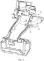
- FIG. 1 illustrates an example power tool 100, according to one embodiment.
- the power tool includes a housing 105, a battery pack interface 110, a driver 115 (e.g., a chuck or bit holder), and a contactless trigger assembly 200.
- the power tool 100 may further have a mode selection device.
- the mode selection device may be a forward-reverse selector 204, which can allow a user to control the direction of a rotating portion of the tool.
- FIG. 1 shows a specific power tool with a rotational output, it is contemplated that the herein described contactless trigger designs may be used with multiple types of power tools, such as drills, drivers, impact drivers, impulse drivers, saws (e.g.
- band saws circular saws, miter saws, and the like
- lights hammer drills, nail guns, staple guns, liquid dispenser (e.g. caulk guns), crimping and/or clamping devices, or another type of power tool that uses a brushless DC motor that is controlled via a user input (e.g. a trigger).
- hammer drills nail guns, staple guns, liquid dispenser (e.g. caulk guns), crimping and/or clamping devices, or another type of power tool that uses a brushless DC motor that is controlled via a user input (e.g. a trigger).
- FIG. 2 illustrates a cross-sectioned view of the power tool 100, according to some embodiments.
- the contactless trigger assembly 200 also referred as the trigger 200
- the forward-reverse selector 204 also referred to as the selector 204 are types of user inputs to a controller associated with the tool 100, as will be described below.
- the trigger 200 may produce an analog signal indicative of a desired speed or torque that varies based on the travel distance of a trigger shoe 228.
- an analog magnetic sensor may be in communication with a magnet within the contactless trigger assembly 200.
- the forward-reverse selector 204 which may be considered part of the contactless trigger assembly, may be able to be moved from a first discrete position to a second discrete position.
- the forward-reverse selector 204 may include a magnet that is in communication with a magnetic sensor, such as a digital magnetic sensor, thereby outputting a signal to a controller of the tool 100 based on the position of the forward-reverse selector 204.
- a magnetic sensor such as a digital magnetic sensor
- An example of such a controller is described further below (see motor controller 930 in FIG. 15 ).
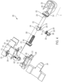
- FIGS. 3 and 4 illustrate a detailed view of the contactless trigger assembly 200, according to some embodiments.
- the contactless trigger assembly 200 includes a housing 208 with a first housing section 212 and a second housing section 216 that are removably couplable to one another.
- the first housing section 212 includes rails 220 extending from a first surface 224 of the housing 208.
- the first surface 224 of the housing 208 is defined by both the first housing section 212 and the second housing section 216 when the first and second housing sections 212, 216 are coupled.
- the rails 220 are positioned to allow the trigger shoe 228 to slide along a length of the rails 220, such that the travel distance of the trigger shoe 228 may be actualized.
- the first surface 224 of the housing 208 further includes a moveable plunger 232 extending therefrom.
- the moveable plunger 232 includes a first end 236 that is sized to be received by a circular recessed portion 240 of the trigger shoe 228, such that the trigger shoe 228 and the moveable plunger 232 are coupled, providing in sync movement between the trigger shoe 228 and the moveable plunger 232.
- the diameter of the circular recessed portion 240 is not significantly larger than the diameter of the moveable plunger 232, allowing a tight fitting between the moveable plunger 232 and the trigger shoe 228.
- the moveable plunger 232 and the trigger shoe 228 may be coupled via alternate means such as fasteners, adhesive, or the like.
- the housing 208 may be omitted, and the above components may be installed directly within the housing 105 of the tool 100.
- a second end 244 of the moveable plunger 232 is disposed in an internal portion 238 of the housing 208.
- the first surface 224 includes a hole 248, with an opening member 252 disposed in the hole 248.
- the moveable plunger 232 is disposed in the opening member 252 such that the moveable plunger 232 slides on an annular surface 254 of the opening member 252, with the first end 236 of the moveable plunger 232 being disposed externally of the housing 208 and the second end 244 of the moveable plunger 232 being disposed internally of the housing 208.
- the second end 244 of the moveable plunger 232 includes a recessed portion 256 (see FIG.
- the recessed portion 256 of the moveable plunger 232 includes a length that is sized to allow the moveable plunger 232 to move the travel distance, such that the trigger shoe 228 moves the travel distance.
- a spring 268 is disposed on the stationary rod 260 and an external surface of the second end 244 of the moveable plunger 232, with the spring 268 being disposed between a plate 272 of the stationary rod 260 and a cam 276 of the moveable plunger 232.
- the plate 272 of the stationary rod 260 is directly coupled to the internal surface 264 of the housing 208.
- the cam 276 of the moveable plunger 232 includes a diameter that is larger than the diameter of the spring 268, such that the spring 268 biases a first surface 280 of the cam 276.
- the cam 276 prevents the second end 244 of the moveable plunger 232 from exiting the internal portion 238 of the housing 208 due to the cam 276 having a larger diameter than that of the opening member 252.
- the spring 268 biases the first surface 280 of the moveable plunger 232 along an axis A, such that a second surface of the moveable plunger 232 interfaces with the opening member 252.
- the internal portion 238 of the housing 208 further includes an annular magnet 284 coupled to the cam 276 of the moveable plunger 232 via an arm 288.
- the arm 288 is moveably coupled to the cam 276 via a first pin 292 of the arm 288.
- the arm 288 is also permanently coupled to the annular magnet 284 via a projection 293. Accordingly, as the moveable plunger 232 moves along the axis A, the arm 288 is rotated about an axis B, which intersects the center of the annular magnet 284, in a direction C. As the arm 288 rotates in the direction C, the annular magnet 284 also rotates in the direction C.
- the analog magnetic sensor is an analog rotational magnetic field sensor.
- the analog rotational magnetic field sensor may be configured to output a linear voltage to a controller of the tool 100 (see, e.g., motor controller 930 of FIG. 15 ).
- the linear voltage may be indicative of a position of the trigger shoe 228, and may be used to control an associated parameter of the tool 100, such as the rotational speed of a motor.
- the annular magnet 284 may also be in communication with a digital magnetic sensor.
- the digital magnetic sensor may be configured to transition from a first state to a second state based on detecting a change of the magnetic field produced by the annular magnet 284 in response to rotating as the trigger shoe 228 is depressed.
- the digital magnetic sensor outputs a first value when the rotation magnet produces a magnetic field indicative of the magnet being in a first predefined position (e.g. associated with a fully released trigger shoe 228).
- the rotational magnetic sensor may then be configured to provide a second value when the magnet transitions away from the first predefined position.
- the transitional output of the digital magnetic sensor may provide an input to a controller of the tool 100 (see, e.g., motor controller 930 of FIG. 15 ), which indicates that the controller should turn on (e.g., a wake-up signal).
- the annular magnet 284 may be in communication with only a digital magnetic sensor. For example, in some embodiments, where the tool 100 operates at a single speed or includes a separate speed adjusting mechanism (e.g., a speed dial), only a digital magnetic sensor is included to detect the annular magnet 284.
- the spring 268 biases the moveable plunger 232 and, thus, the trigger shoe 228, to an extended position relative to the first surface 224 of the housing 208.
- the annular magnet 284 is in a first position, with a first magnetic field relative to the PCB 418, which the analog rotational magnetic field sensor detects.
- the first magnetic field detected by the analog rotational magnetic field sensor is then converted to a first output value, which is then received by a controller of the tool 100.
- the trigger shoe 228 moves the moveable plunger 232 along the axis A, such that the trigger shoe 228 moves toward the first surface 224 of the housing 208.
- Movement of the moveable plunger 232 biases the spring 268 toward the plate 272 of the stationary rod 260, thereby, also moving the cam 276 toward the plate 272.
- This causes the arm 288 to pivot about the axis B, rotating the annular magnet 284 about the axis B in the direction C.
- the annular magnet 284 is in a second position, with a second magnetic field relative to the PCB 418, which the analog rotational magnetic field sensor detects.
- the second magnetic field detected by the analog rotational magnetic field sensor is then converted to a second output voltage that is distinct from the first output voltage, which is then received by the controller of the tool 100.
- the spring 268 biases the cam 276, which moves the moveable plunger 232 and, thus, the trigger shoe 228, along the axis A in a direction away from the first surface 224 of the housing 208. Movement of the cam 276 causes the arm 288 to pivot about the axis B in a direction opposite to that of the direction C. The annular magnet 284 is therefore rotated in the opposite direction to that of the direction C until movement of the cam 276 is inhibited by the opening member 252. At this time, the annular magnet 284 is in the first position, with the first magnetic field, which the analog rotational magnetic field sensor detects. The first magnetic field detected by the analog rotational magnetic field sensor is then converted to the first output voltage, which is then received by the controller of the tool 100.
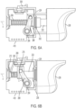
- the contactless trigger 200 includes the forward-reverse selector 204, as described above.
- a camming assembly 300 communicates with recessed portion walls 304 of the selector 204 via a selector arm 308 (see also FIG. 6 ) that has a portion extending through an opening 312 (see also FIG. 4 ) of the housing 208.
- the opening 312 is defined by both the first housing section 212 and the second housing section 216, on a second surface 314 of the housing 208 that is perpendicular to the first surface 224 of the housing 208.
- the selector arm 308 includes a center pin portion 316, an intermediate portion 320, and an upwardly extending portion 324.
- the center pin portion 316 extends through the opening 312 of the housing 208, such that the center pin portion 316 is positioned both in the internal portion 238 of the housing 208 and externally from the housing 208.
- An end of the center pin portion 316 that is in the internal portion 238 of the housing 208 is coupled to a magnet 328.
- the intermediate portion 320 is disposed externally of the housing 208 and is integrally connected to the center pin portion 316.
- the intermediate portion 320 extends away from the opening 312 of the housing 208, along the second surface 314.
- the upwardly extending portion 324 is integrally connected to the intermediate portion 320 and is perpendicular to the intermediate portion 320, such that the upwardly extending portion 324 extends away from the second surface 314.
- the upwardly extending portion 324 includes a first side 332 and a second side 336 opposite the first side 332, the first side 332 and the second side 336 are curved (shown in FIG. 9 ).
- a ball detent 340 is disposed in a recess in the internal portion 238 of the housing 208.
- the ball detent 340 is biased toward an outside surface of the end of the center pin portion 316 via a ball detent spring 344 (see FIG. 7 ).
- the outside surface of the center pin portion 316 includes a first recession 348, a second recession 350, and a third recession 352, each sized to receive the ball detent 340.
- the selector 204 may move along an axis D in a first direction and a second direction, the second direction being opposite from the first direction.
- a first wall 356 of the recessed portion walls 304 of the selector 204 comes into contact with the first side 332 of the upwardly extending portion 324. Since the first side 332 is curved, as the first wall 356 biases the first side 332, the upwardly extending portion 324 rotates the intermediate portion 320 and, thus, the center pin portion 316, about an axis E (see FIGS. 8 , 10A), which extends through the center of the center pin portion 316, in a direction F (see FIG.
- the ball detent 340 is moved out of the second recession 350, which acts as a neutral positon, and along the outside surface of the center pin portion 340.
- the center pin portion 316 continues to rotate. Continued rotation of the center pin portion 316 and, thus, the magnet 328, is inhibited by the ball detent 340 being received in the first recession 348, such that the center pin portion 316 is locked in a first position (shown in FIG. 10B ).
- a second wall 360 of the recessed portion walls 304 of the selector 204 comes into contact with the second side 336 of the upwardly extending portion 324. Since the second side 336 is curved, as the second wall 360 biases the second side 336, the upwardly extending portion 324 rotates the intermediate portion 320 and, thus, the center pin portion 316, about the axis E in a direction opposite to that of the direction F. As the second wall 360 continues to bias the second side 336, the center pin potion 316 continues to rotate.
- the magnetic field of the magnet 328 varies relative to stationary elements of the assembly, such as the PCB 418.
- This variation of the magnetic field is detected by a magnetic field sensor 420 located on the PCB 418.
- the magnetic field sensor 420 is a digital magnetic field sensor configured to transition from a first digital level to a second digital level based on the digital magnetic field sensor detecting a change in the magnetic polarity of the magnet 328. The change in polarity is caused by the rotation of the magnet 328 and its associated poles.
- the PCB 418 may extend out of a housing 208 of the contactless trigger assembly 200. This configuration can allow the PCB 418 to extend into the tool 100, thereby providing additional PCB space. For example, as illustrated in FIGS. 3 and 8 , a portion of the PCB 418 extends downward out of the housing 208.
- FIGS. 11-12 are a functional diagram illustrating the annular magnet 508 in communication with an analog magnet sensor 600 and a digital magnetic sensor 602, according to some embodiments.
- the analog magnet sensor 600 and the digital magnetic sensor 602 are both mounted on the PCB 418, described above.
- the annular magnet 508 is in a position associated with the trigger shoe 228 being in a fully released position.
- the analog magnetic sensor 600 is detecting a magnetic field generated by the annular magnet.
- the magnetic field is a result of the magnet flux received by the analog sensor based on the analog sensor 600 being located at an angle of ⁇ A from a centerline axis 604 of the annular magnet 508.
- the digital magnetic sensor 602 detects a magnetic field based on the digital sensor 602 being located at an angle of ⁇ B from the centerline axis 604.
- the digital magnetic sensor 602 may be an omnidirectional Hall effect sensor with a normally high state that goes low as the magnet transitions to a different polarity, thereby making the digital sensor 602 insensitive to strong external fields.
- the annular magnet 508 is shown to have two poles (for example, a north pole and a south pole). As shown in FIG. 11 , the boundary between the two poles bisects the diameter of the magnet.
- a similar magnet design is used in regards to the forward/reverse selector 204.
- FIG. 12 shows the annular magnet being in a position associated with the trigger shoe 228 being in a fully pulled positon.
- the annular magnet is now positioned such that the south pole of the magnet is positioned in proximity to the analog magnetic sensor 600, such that the analog magnetic sensor 600 receiving a magnetic field based on the analog sensor being located at an angle of ⁇ A to the centerline 604.
- the annular magnet is now positioned such that the north pole of the magnet is positioned in proximity to the digital magnetic sensor 602, and is receiving a magnetic field based on the digital sensor 602 being located at an angle of ⁇ B to the centerline 604.
- Both the analog sensor 600 and the digital sensor 602 may be rotational Hall effect magnetic sensors that are configured to measure a magnetic flux density vector component that enters the face of the sensor, and outputs either a linear proportional signal, or a digital signal.
- the magnetic sensors 600, 602 are not being used to measure a flux based on a distance to a magnetic element. Rather, the magnetic sensors 600, 602 measure an angle of the respective sensor to the magnet based on a received magnetic flux density vector component, thereby allowing the distance between the sensors 600, 602 and the magnet to remain constant during operation.
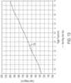
- FIG. 13 is a graph showing an example output of an analog magnetic sensor, such as magnetic sensor 600, in relation to travel distance of the trigger shoe 228.
- the output of the analog sensor increases in a generally linear fashion as the trigger shoe 228 moves from an initial relaxed position (depressed 0 mm) to a fully depressed position (depressed 8 mm), as shown by output trend line 700.
- the particular voltage levels and travel distances are merely examples, as different levels and distances are used in other embodiments.
- the relationship between the travel distance of the trigger shoe 228 and the analog output of the magnetic sensor 600 is non-linear, such as logarithmic or exponential.
- the output of the magnetic sensor 600 is a voltage. However, in other embodiments, the output is a current (e.g. 4-20mA) or a digital value.
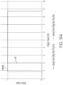
- FIG. 14A is a graph showing an example output of a digital magnetic sensor, such as magnet sensor 602 and/or the digital magnetic sensor 420 used by the forward-reverse selector 204.
- the output of the digital sensor varies between a digital high ("1"), and a digital low ("0").
- the digital magnetic sensor 602 transitions to a digital high when the trigger shoe 228 travel is approximately 2 mm.
- the digital magnetic sensor 602 may be configured to transition to a digital high when the trigger shoe 228 travel distance is less than 2 mm or greater than 2 mm in some embodiments.
- the digital sensor is further shown to transition back to a digital low during the release of the trigger shoe 228.
- the digital sensor 602 may transition back to a digital low when the trigger shoe 228 is within 0.9 mm of the fully released position.
- the digital magnetic sensor 602 may also be configured to transition to a digital low when the trigger shoe 228 is less than 0.9 mm of the fully released position, or more than 0.9 mm of the fully released position.
- a transition between a digital high and a digital low may also be output by the digital magnetic sensor 420 used by the forward-reverse selector 204.
- the digital magnetic sensor 420 may output a digital high when the forward-reverse selector 204 is in the first locked position.
- the digital magnetic sensor 420 may output a digital high when the forward-reverse selector 204 is in the second locked position.
- the digital magnetic sensor 420 may transition to a digital low signal when the forward-reverse selector 204 is moved out of either the first locked position or the second locked position, depending on the configuration of the tool.
- the digital magnetic sensor 420 may only transition between digital states when the forward-reverse selector 204 is moved to one of the first or second locked positions. For example, the digital magnetic sensor 420 may transition to a digital high when the forward-reverse selector 204 is placed in the first locked position, and transition to a digital low when the forward-reverse selector is placed in the second locked position, or vice versa.
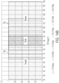
- FIG. 14B is a graph showing an example output of a dual output digital magnetic sensor, such as the digital magnetic sensor 420 used by the forward-reverse selector 204 in some embodiments.
- the digital magnetic sensor 420 may be configured to output a first digital high at a first output when the forward-reverse selector 204 is in a first position, a second digital high at a second output when the forward-reverse selector 204 is in a second position, and a digital low on both the first output and the second output when the forward-reverse selector 204 is in a third position.
- a first digital high 750 may be output via the first output of the digital magnetic sensor 420.
- a second digital high 752 is output via the second output of the digital magnetic sensor 420.
- the first and second outputs may be in communication with a controller via two or more I/O ports of the controller.
- the transitions to digital highs can be varied based on a desired amount of rotation of the magnet 328. For example, a rotation of 5 degrees may be sufficient to cause a transition from the digital magnetic sensor 420. However, rotations of more than 5 degrees or less than 5 degrees are also contemplated.
- the power source 922 may receive AC power (e.g., 120V/60Hz mains power) from a tool plug that is coupled to a standard wall outlet, and then filter, condition, and rectify the received power to output DC power.
- Each Hall-effect sensor 928 outputs motor feedback information, such as an indication (e.g., a pulse) when a magnet of the rotor rotates across the face of that Hall-effect sensor 928.
- the motor controller 930 can determine the position, velocity, and acceleration of the rotor.
- the digital sensor 420 may provide a control signal (e.g., a digital signal) to the controller indicating a position of the forward-reverse selector 204, which in turn instructs the controller 930 to operate the motor 926 in either a forward or reverse direction, which may be controlled via the power switching network 924, as described below.
- a control signal e.g., a digital signal
- the motor controller 930 transmits control signals to the power switching network 924 to drive the motor 926, as explained in further detail with respect to FIG. 16 .
- the power tool 100 may be a sensorless power tool that does not include a Hall-effect sensor 928 or other position sensors to detect the position of a rotor of the motor 926. Rather, the rotor position may be detected based on the inductance of the motor 926 or the back electromotive force (emf) generated in the motor 926.
- the motor controller 930 and other components of the power tool 100 are electrically coupled to the power source 922 such that the power source 922 provides power thereto.
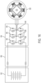
- FIG. 16 illustrates a circuit diagram of the power switching network 924.
- the power switching network 924 includes a number of high side power switching elements 940 (e.g., field effect transistors [FETs]) and a number of low side power switching elements 944 (e.g., FETs).
- the motor controller 930 provides the control signals to control the high side FETs 940 and the low side FETs 944 to drive the motor based on the motor feedback information and user controls described above.
- the motor controller 930 in response to detecting a pull of the trigger shoe 228 and the input from forward-reverse selector 204, the motor controller 930 provides the control signals to selectively enable and disable the FETs 940 and 944 (e.g., sequentially, in pairs) resulting in power from the power source 922 to be selectively applied to stator coils of the motor 926 to cause rotation of a rotor. More particularly, to drive the motor 926, the motor controller 920 enables a first high side FET 940 and first low side FET 944 pair (e.g., by providing a voltage at a gate terminal of the FETs) for a first period of time.
- a first high side FET 940 and first low side FET 944 pair e.g., by providing a voltage at a gate terminal of the FETs
- the motor controller 930 In response to determining that the rotor of the motor 926 has rotated based on a pulse from the Hall-effect sensors 928, the motor controller 930 disables the first FET pair, and enables a second high side FET 940 and a second low side FET 944. In response to determining that the rotor of the motor 926 has rotated based on pulse(s) from the Hall-effect sensors 928, the motor controller 930 disables the second FET pair, and enables a third high side FET 940 and a third low side FET 944. This sequence of cyclically enabling pairs of high side FET 940 and low side FET 944 repeats to drive the motor 926.
- control signals include pulse width modulated (PWM) signals having a duty cycle that is set in proportion to the amount of trigger pull of the trigger shoe 228 (as indicated by the output of the magnetic sensor 600), to thereby control the speed or torque of the motor 926.
- PWM pulse width modulated
- FIG. 17 is a process 1700 for controlling the output of an electric power tool, such as power tool 100 is described, according to some embodiments.
- an input trigger of the electric power tool is actuated.
- the input trigger may be the trigger shoe 228 described above.
- other input triggers such as pushbuttons, levers, and the like may also be used.
- the input trigger is actuated in a first linear direction (e.g., a linear pulling of the trigger shoe 228).
- the linear actuation of the input trigger is converted to a rotational movement via one or more mechanical interfaces.
- the linear motion of the input trigger is converted to a rotational movement using the contactless trigger assembly 200 described above.
- other configurations for converting the linear movement of the input trigger to a rotational movement are also contemplated.
- the rotational movement is transferred to a magnet of the electric power tool, such as annular magnet 284 described above.
- the magnet may be coupled to the rotating arm 288 as described above.
- the magnet is rotated based on the actuation of the input trigger.
- an analog sensor detects variation in a magnetic field generated by the rotating magnet.
- the sensor is a rotational Hall-effect magnetic sensor.
- the analog sensor may be configured to detect a change in a magnetic flux density component, which results from the rotation of the magnet.
- the analog sensor converts the sensed magnetic field to an output signal, which may be provided to a controller, such as motor controller 930, as described above.
- the output of the analog sensor is a voltage that varies linearly with the rotation of the magnet as shown in FIG. 13 .
- the output may be a non-linear output, such as a stepped output, a logarithmic output, etc.
- the controller 930 upon receiving the output of the analog sensor, controls an output of the electric tool based on the received analog sensor output.
- the motor controller 930 receives the output from the analog sensor 600 and drives the motor 926 by controlling the power switching network 924 based on the output from the analog sensor 600, as described above.
- the motor controller 930 drives the power switching network 924 to control the output power to the motor 926 in a non-linear operation, as shown in motor drive profile 1800 shown in FIG. 18 .
- a first region 1802 includes lower speeds that allow for more precise control by a user (e.g., through modulating the depressed amount of the shoe 228).
- the second region 1804 allows the tool to reach full speed earlier in the output range of the sensor (e.g. earlier in the trigger pull).
- the controller 930 may be configured to operate the output of the tool at 100% power (e.g., with a pulse width modulated signal driving the power switching network 924 at 100 % duty ratio) when the trigger pull reaches 60% of full travel. This arrangement enables the output of the tool to be at 100 % power across the tolerance range of the trigger shoe 228 or other input trigger.
- the output of the electric tool may be a rotational output, wherein the controller controls the rotational speed of the rotational output based on the received sensor output.
- the controller also receives a control signal from the magnetic sensor 420 associated with the forward-reverse selector 204.
- the motor controller 930 may then control the output of the power tool based on both the received output of the analog sensor 600 and the control signal from the magnetic sensor 420 to control the output of the tool at a desired output level and also in the desired direction.
- a digital magnetic sensor such as digital magnetic sensor 602 senses the variation in the magnetic field in addition to or instead of the analog sensor.
- the digital magnetic sensors convert the sensed magnetic field to a digital output, such as that shown in FIG. 14 , at process block 1710.
- the digital output may be received by the controller 930 of the electric tool to initiate certain functions, such as instructing the controller to "wake-up” or initialize in order to operate the tool. For example, if the digital magnetic sensors output a digital high to the controller, the controller 930 may "wake-up” or enter a normal mode from a "sleeping" or low-power mode.
- the controller 930 may enter a low-power mode after the electronic tool has been inactive for a predetermined period of time (e.g. two hours).
- the analog sensor 600 is not included and the annular magnet 284 is in communication with only the digital magnetic sensor 602.
- the tool 100 operates at a single speed, includes a separate speed adjusting mechanism (e.g., a jigsaw with a speed dial), or is a tool that includes a cyclic motor operation that is enabled upon a trigger pull (e.g., a nailer or stapler), only the digital sensor 602 is included to detect the annular magnet 284.
- the control signal from the digital sensor 602 to the motor controller 930 acts as an enable signal to the controller 930 and, in process step 1712, the controller 930 drives the motor 926 in response to receiving the enable signal from the digital sensor 602.
- FIGS. 19A-19C illustrate an alternative embodiment of a contactless trigger assembly 1900, such as contactless trigger assembly 200 described above.
- the contactless trigger assembly 1900 includes a printed circuit board 1902, and an arm 1904. Similar to the contactless trigger assembly 200, the arm 1904 may be moveably coupled to a cam 1906 of a moveable plunger 1908. As the moveable plunger 1908 moves along the axis A, the arm 1904 is rotated in direction C.
- the contactless trigger assembly 1900 further includes a metallic member 1910 coupled to the arm 1904 at a pivoting cam 1912, and is configured to rotate with the arm 1904. In one embodiment, the metallic member 1910 is constructed out of a ferrous material.
- the metallic member 1910 may be constructed out of a non-ferrous material.
- Example metallic materials may include iron, steel, aluminum, copper, and the like.
- An inductive coil 1914 is coupled to the circuit board 1902, and is positioned between the circuit board 1902 and the arm 1904. In some embodiments, an electrical current is provided to the inductive coil to generate a magnetic field.
- the metallic member 1910 As the arm 1904 rotates in a direction C, the metallic member 1910 also rotates in the direction C. As shown in FIG. 19 , the metallic member 1910 and the inductive coil 1914 are not contiguous annular shapes, but rather are curved arcs that, depending on the position of the movable plunger, overlap by a certain degree. Rotation of the metallic member 1910 causes the amount of the ferrous member 1910 to vary, thereby altering a strength of a magnetic field generated by the inductive coil 1914, which is in turn detected by a sensor on the printed circuit board 1902. The variance in the sensed magnetic field may be correlated to a position of the trigger. Sensing the strength of a varying magnetic field eliminates the need for a rotational magnetic field sensor. In one embodiment, the sensor is an analog rotational magnetic field sensor. In other embodiments, the sensor is an inductive sensor configured to sense the strength of the magnetic field generated by the inductive coil 1914.
- the arm 1904 rotates in a direction C along with the ferrous member 1910.
- the portion of the inductive coil 1914 covered by the metallic member 1910 changes.
- the trigger (not shown) is in the relaxed position causing the arm to be in a first position.
- the metallic member 1910 is positioned such that it covers the entire length of the inductive coil 1914.
- the portion of the metallic member 1910 covering the inductive coil 1914 is reduced by a value proportional to the movement of the arm 1904.
- the arm 1904 reaches the maximum travel position, as shown in FIG.
- the portion of the metallic member 1910 covering the inductive coil 1914 is further reduced.
- a magnetic field is varied, which is detected by the sensor.
- the sensor is configured to provide an output to a controller, such as motor controller 930, representative of the sensed inductive value, which may then be used to control an output of a power tool, such as described above.
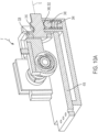
- FIGS. 20A-20C illustrates an alternative embodiment of the contactless trigger assembly 1900 as contactless trigger assembly 2000.
- the components and operation of the trigger assembly 200 are similar to that of trigger assembly 1900, and it is understood that the components and operation of the contactless trigger assembly 2000 are the same as those in contactless trigger assembly 1900, unless noted otherwise below.
- the inductive coil 1914 is positioned such that no part of the metallic member 1910 covers the inductive coil 1914 when the trigger is in the relaxed position (e.g. not depressed).
- the trigger (not shown) is in the relaxed (e.g. not depressed) position causing the arm to be in a first position.
- the sine-cosine sensor can achieve a resolution of approximately 0.15° for detecting the position of the metallic member 1910, and a detection accuracy of greater than 98%.
Landscapes
- Engineering & Computer Science (AREA)
- Mechanical Engineering (AREA)
- Physics & Mathematics (AREA)
- Condensed Matter Physics & Semiconductors (AREA)
- General Physics & Mathematics (AREA)
- Switches That Are Operated By Magnetic Or Electric Fields (AREA)
- Measurement Of Length, Angles, Or The Like Using Electric Or Magnetic Means (AREA)
Claims (15)
- Auslöser-Baugruppe (200) für ein Elektrowerkzeug (100), umfassend:ein Gehäuse (208);einen beweglichen Stößel (232), der sich von einer Oberfläche (224) des Gehäuses erstreckt, wobei der bewegliche Stößel ein erstes Ende (236), das außerhalb des Gehäuses angeordnet ist, und ein zweites Ende (244), das innerhalb des Gehäuses angeordnet ist, einschließt;einen Auslöserschuh (228), der mit dem ersten Ende des beweglichen Stößels gekoppelt ist;einen Arm (288), der eine erste Seite, die beweglich mit dem zweiten Ende des beweglichen Stößels verbunden ist, und eine zweite Seite, die mit einem ringförmigen Magneten (284) gekoppelt ist, einschließt; undeinen Sensor (600), der dafür konfiguriert ist, ein Magnetfeld des ringförmigen Magneten zu erfassen,wobei eine Bewegung des Auslöserschuhs den ringförmigen Magneten um eine Mittelachse (B) des ringförmigen Magneten dreht und das durch den Sensor erfasste Magnetfeld verändert.
- Auslöser-Baugruppe nach Anspruch 1, wobei der Sensor mit einer Steuerungseinrichtung (930) des Elektrowerkzeugs elektrisch verbunden ist, wobei die Steuerungseinrichtung dafür konfiguriert ist, eine Ausgabe des Elektrowerkzeugs zu steuern.
- Auslöser-Baugruppe nach Anspruch 2, wobei der Sensor dafür konfiguriert ist, auf der Grundlage des erfassten Magnetfelds ein Signal an die Steuerungseinrichtung auszugeben;
und optional
wobei die Ausgabe eine Spannung ist, die eine Position des Auslöserschuhs angibt. - Auslöser-Baugruppe nach Anspruch 1, wobei der Sensor dafür konfiguriert ist, eine Änderung des Magnetfelds des ringförmigen Magneten als Antwort darauf, dass der ringförmige Magnet sich dreht, zu erfassen.
- Auslöser-Baugruppe nach Anspruch 1, ferner umfassend:einen Auswahlschalter (204), der auf einer Oberfläche des Gehäuses angeordnet ist;einen Stift (308), der ein erstes Ende (324), das mit dem Auswahlschalter in Eingriff gebracht werden kann, und ein zweites Ende (316), das mit einem Auswahlschalter-Magneten (328) gekoppelt ist, einschließt; undeinen Auswahlschalter-Sensor (420), der dafür konfiguriert ist, ein Magnetfeld des Auswahlschalter-Magneten zu erfassen,wobei eine axiale Bewegung des Auswahlschalters den Auswahlschalter-Magneten dreht und das durch den Sensor erfasste Magnetfeld verändert.
- Auslöser-Baugruppe nach Anspruch 5, wobei der Auswahlschalter-Sensor dafür konfiguriert ist, eine Polarität des Auswahlschalter-Magneten zu erfassen, und auf der Grundlage der erfassten Polarität ein digitales Signal an eine Steuerungseinrichtung (930) auszugeben.
- Auslöser-Baugruppe nach Anspruch 6, wobei die Steuerungseinrichtung dafür konfiguriert ist, eine Betriebsart auszuführen, die auf der Grundlage des vom Auswahlschalter-Sensor empfangenen digitalen Signals aus einer Vielzahl von Betriebsarten des Elektrowerkzeugs ausgewählt wird;
und optional
wobei die Vielzahl von Betriebsarten eine Vorwärtsbetriebsart und eine Rückwärtsbetriebsart umfasst. - Verfahren zum Steuern einer Ausgabe eines elektrischen Elektrowerkzeugs (100), wobei das Verfahren Folgendes umfasst:Betätigen eines Auslöserschuhs (228) des elektrischen Elektrowerkzeugs in einer ersten linearen Richtung, wobei die Betätigung des Auslöserschuhs einen beweglichen Stößel (232) in der ersten linearen Richtung bewegt;Umsetzen einer linearen Bewegung des beweglichen Stößels in eine Drehbewegung eines beweglichen Arms (288) in einer ersten Drehrichtung;Drehen eines ringförmigen Magneten (284), der mit dem beweglichen Arm gekoppelt ist, in der ersten Drehrichtung, wobei der ringförmige Magnet um eine Mittelachse (B) des ringförmigen Magneten gedreht wird;Erfassen eines Parameters eines durch den ringförmigen Magneten erzeugten Magnetfelds an einem ersten Magnetsensor (600);Umsetzen des Parameters des Magnetfelds in eine Ausgangsspannung; undEmpfangen der Ausgangsspannung an einer Steuerungseinrichtung (930) des elektrischen Elektrowerkzeugs; undSteuern der Ausgabe des elektrischen Elektrowerkzeugs über die Steuerungseinrichtung auf der Grundlage der empfangenen Ausgangsspannung.
- Verfahren nach Anspruch 8, wobei die Ausgabe des elektrischen Elektrowerkzeugs eine Drehzahl ist.
- Verfahren nach Anspruch 8, wobei der erfasste Parameter eine Vektorkomponente der magnetischen Flussdichte ist.
- Verfahren nach Anspruch 8, wobei der erste Magnetsensor ein analoger Rotationsmagnetfeldsensor (600) ist.
- Verfahren nach Anspruch 8, ferner umfassend das Erfassen eines Parameters des durch den ringförmigen Magneten erzeugten Magnetfelds an einem zweiten Magnetsensor, wobei der zweite Magnetsensor ein digitaler Magnetsensor (602) ist;
und optional
ferner umfassend das Einleiten eines Aufwachprozesses für die Steuerungseinrichtung, darauf basierend, dass die Steuerungseinrichtung eine Ausgabe des zweiten Magnetsensors empfängt. - Elektrowerkzeug (100), umfassend:
die Auslöser-Baugruppe nach Anspruch 2, wobei:der Auslöserschuh dafür konfiguriert ist, in einer ersten linearen Richtung betätigt zu werden, wobei eine Betätigung des Auslöserschuhs den beweglichen Stößel in der ersten linearen Richtung bewegt,der Arm ein beweglicher Arm ist, der dafür konfiguriert ist, eine lineare Bewegung des beweglichen Stößels in eine Drehbewegung des beweglichen Arms in einer ersten Drehrichtung umzusetzen, der bewegliche Arm ferner dafür konfiguriert ist, den mit dem beweglichen Arm gekoppelten ringförmigen Magneten in der ersten Drehrichtung um die Mittelachse des ringförmigen Magneten zu drehen, undder Sensor ein Magnetsensor ist, der dafür konfiguriert ist, einen ersten Parameter des durch den ringförmigen Magneten erzeugten Magnetfelds zu erfassen, wobei der Magnetsensor dafür konfiguriert ist, das Magnetfeld in eine Ausgangsspannung umzusetzen, die eine Position des Auslöserschuhs darstellt; unddie Steuerungseinrichtung dafür konfiguriert ist, die Ausgangsspannung vom Magnetsensor zu empfangen und die Ausgabe des Elektrowerkzeugs auf der Grundlage der empfangenen Ausgangsspannung zu steuern. - Elektrowerkzeug nach Anspruch 13, wobei die Ausgabe des Elektrowerkzeugs eine Drehzahl ist.
- Elektrowerkzeug nach Anspruch 13, ferner umfassend:einen zweiten Magnetsensor (602), der dafür konfiguriert ist, einen zweiten Parameter des ringförmigen Magneten zu erfassen und eine Ausgabe an die Steuerungseinrichtung zu übertragen, wobei der zweite Magnetsensor ein digitaler Magnetsensor ist, und der zweite Parameter eine Polarität des ringförmigen Magneten ist;und optionalwobei die Steuerungseinrichtung ferner dafür konfiguriert ist, einen Aufwachprozess für die Steuerungseinrichtung darauf basierend einzuleiten, dass die Steuerungseinrichtung die Ausgabe des zweiten Magnetsensors empfängt.
Applications Claiming Priority (3)
| Application Number | Priority Date | Filing Date | Title |
|---|---|---|---|
| US201962847103P | 2019-05-13 | 2019-05-13 | |
| US201962870353P | 2019-07-03 | 2019-07-03 | |
| PCT/US2020/032442 WO2020231974A1 (en) | 2019-05-13 | 2020-05-12 | Contactless trigger with rotational magnetic sensor for a power tool |
Publications (3)
| Publication Number | Publication Date |
|---|---|
| EP3970175A1 EP3970175A1 (de) | 2022-03-23 |
| EP3970175A4 EP3970175A4 (de) | 2023-01-11 |
| EP3970175B1 true EP3970175B1 (de) | 2025-04-30 |
Family
ID=73289276
Family Applications (1)
| Application Number | Title | Priority Date | Filing Date |
|---|---|---|---|
| EP20806375.0A Active EP3970175B1 (de) | 2019-05-13 | 2020-05-12 | Kontaktloser auslöser mit drehmagnetsensor für ein elektrowerkzeug |
Country Status (4)
| Country | Link |
|---|---|
| US (3) | US11890741B2 (de) |
| EP (1) | EP3970175B1 (de) |
| CN (1) | CN114096382B (de) |
| WO (1) | WO2020231974A1 (de) |
Families Citing this family (9)
| Publication number | Priority date | Publication date | Assignee | Title |
|---|---|---|---|---|
| WO2020182273A1 (en) * | 2019-03-08 | 2020-09-17 | Mirka Oy | Trigger apparatus for powered device, powered device, and method of controlling an operation of a powered device |
| WO2020231974A1 (en) | 2019-05-13 | 2020-11-19 | Milwaukee Electric Tool Corporation | Contactless trigger with rotational magnetic sensor for a power tool |
| EP3822035A1 (de) * | 2019-11-14 | 2021-05-19 | Hilti Aktiengesellschaft | Handgriffvorrichtung für eine werkzeugmaschine |
| US20220167982A1 (en) * | 2020-12-02 | 2022-06-02 | Ethicon Llc | Surgical instruments with electrical connectors for power transmission across sterile barrier |
| JP2022118534A (ja) | 2021-02-02 | 2022-08-15 | オムロン株式会社 | トリガスイッチ |
| CN114868513A (zh) | 2021-02-05 | 2022-08-09 | 米沃奇电动工具公司 | 用于割草机的非接触开关 |
| EP4124413A1 (de) * | 2021-07-30 | 2023-02-01 | Hilti Aktiengesellschaft | Verfahren zum steuern und regeln einer werkzeugmaschine |
| CN114582648A (zh) * | 2022-02-28 | 2022-06-03 | 维沃移动通信有限公司 | 一种电子设备 |
| US20240083008A1 (en) * | 2022-09-09 | 2024-03-14 | Milwaukee Electric Tool Corporation | Trigger mechanism for power tool |
Family Cites Families (89)
| Publication number | Priority date | Publication date | Assignee | Title |
|---|---|---|---|---|
| DE19825433A1 (de) | 1997-07-23 | 1999-01-28 | Mannesmann Vdo Ag | Magnetischer Positionssensor |
| DE3637128A1 (de) | 1986-10-31 | 1988-05-05 | Hilti Ag | Einrichtung zur automatischen werkzeugspezifischen betriebsdateneinstellung eines elektrischen antriebsgeraets fuer auswechselbare werkzeuge |
| DE3720512A1 (de) | 1987-06-20 | 1988-12-29 | Hilti Ag | Handgeraet |
| US5014793A (en) | 1989-04-10 | 1991-05-14 | Measurement Specialties, Inc. | Variable speed DC motor controller apparatus particularly adapted for control of portable-power tools |
| US5365155A (en) | 1990-10-22 | 1994-11-15 | Marquardt Gmbh | Rotational speed control and use of same to control the rotational speed of an electric hand tool motor |
| US5235261A (en) | 1991-06-27 | 1993-08-10 | Stryker Corporation | DC powered surgical handpiece having a motor control circuit |
| DE9211412U1 (de) | 1992-08-28 | 1992-12-17 | As-Motor Gmbh U. Co Kg, 7163 Oberrot | Arbeitsgerät, insbesondere elektrischer Rasenmäher |
| US5847908A (en) | 1997-12-17 | 1998-12-08 | Ingersoll-Rand Company | Machine having current loss shutdown circuit with low resistance relay |
| DE19953204A1 (de) * | 1999-11-05 | 2001-05-10 | Valeo Schalter & Sensoren Gmbh | Schaltmodul zum Schalten von Steuerstrombahnen, insbesondere in Fahrzeugen |
| US7101300B2 (en) * | 2001-01-23 | 2006-09-05 | Black & Decker Inc. | Multispeed power tool transmission |
| DE10212721A1 (de) | 2001-03-24 | 2002-09-26 | Marquardt Gmbh | Ansteuereinrichtung für einen Elektromotor |
| JP3776772B2 (ja) | 2001-08-22 | 2006-05-17 | 本田技研工業株式会社 | 電動芝刈機 |
| JP3973459B2 (ja) | 2002-03-15 | 2007-09-12 | 株式会社マキタ | バッテリ駆動式電動工具およびバッテリ駆動式電動工具の使用方法 |
| JP3765081B2 (ja) | 2002-04-26 | 2006-04-12 | 株式会社マキタ | バッテリ駆動式電動工具 |
| US7210541B2 (en) | 2002-09-03 | 2007-05-01 | Microtorq Llc | Transducerized rotary tool |
| US7090030B2 (en) | 2002-09-03 | 2006-08-15 | Microtorq L.L.C. | Tranducerized torque wrench |
| DE10259569A1 (de) | 2002-12-19 | 2004-07-01 | Hilti Ag | Elektrohandwerkzeugmaschine mit kontaktlosem elektrischen Handschalter |
| US7076830B2 (en) | 2003-01-09 | 2006-07-18 | Royal Appliance Mfg. Co. | Electronically commutated drive system for vacuum cleaner |
| JP4286552B2 (ja) | 2003-02-05 | 2009-07-01 | 株式会社マキタ | 電動工具およびソレノイドの駆動方法 |
| DE102004038311A1 (de) | 2003-08-08 | 2005-03-10 | Marquardt Gmbh | Elektrischer Schalter |
| ATE427812T1 (de) | 2004-07-15 | 2009-04-15 | Marquardt Gmbh | Elektrowerkzeug, insbesondere akku- elektrowerkzeug |
| JP4823499B2 (ja) | 2004-07-23 | 2011-11-24 | 勝行 戸津 | ブラシレスモータ駆動回転工具の制御方法 |
| JP4531525B2 (ja) * | 2004-10-21 | 2010-08-25 | 日本電産シバウラ株式会社 | トリガースイッチ |
| ATE419636T1 (de) | 2005-11-16 | 2009-01-15 | Marquardt Gmbh | Elektrowerkzeug, insbesondere akku- elektrowerkzeug |
| DE102005058613A1 (de) | 2005-12-07 | 2007-06-14 | Bosch Rexroth Ag | Werkzeug mit berührungslosem Schalter |
| US20070144753A1 (en) | 2005-12-22 | 2007-06-28 | Microtorq, L.L.C. | Transducerized rotary tool |
| DE102006040647A1 (de) | 2006-08-30 | 2008-03-13 | Robert Bosch Gmbh | Handwerkzeugmaschine |
| ATE489901T1 (de) | 2007-01-17 | 2010-12-15 | W & H Dentalwerk Buermoos Gmbh | Medizinischer handgriff |
| DE102007043035A1 (de) | 2007-09-11 | 2009-03-12 | Tool Express-Service Schraubertechnik Gmbh | Handwerkzeug mit Zwei-Hand-Bedienung |
| TWI379746B (en) | 2007-10-05 | 2012-12-21 | Senco Brands Inc | Fastener driving tool using a gas spring |
| US8763874B2 (en) | 2007-10-05 | 2014-07-01 | Senco Brands, Inc. | Gas spring fastener driving tool with improved lifter and latch mechanisms |
| SE531646C2 (sv) | 2007-10-17 | 2009-06-16 | Atlas Copco Tools Ab | Skruvdragare med organ för övervakning av en reaktionsarm |
| DE102007000454A1 (de) | 2007-11-09 | 2009-05-14 | Hilti Aktiengesellschaft | Schlagende Handwerkzeugmaschine mit kontaktlosen Handschalter im Seitenhandgriff |
| DE102008014506A1 (de) | 2008-03-15 | 2009-09-17 | Wabco Gmbh | Zylinder |
| DE102008001154B4 (de) | 2008-04-14 | 2022-01-27 | Robert Bosch Gmbh | Elektrohandwerkzeug mit einer Betätigungsvorrichtung und einem Antriebsmotor |
| JP5255920B2 (ja) | 2008-06-16 | 2013-08-07 | 株式会社マキタ | 動力工具 |
| FR2935106B1 (fr) | 2008-08-22 | 2010-09-17 | Pellenc Sa | Outil electroportatif a commande par gachette |
| JP5512110B2 (ja) | 2008-09-26 | 2014-06-04 | 株式会社マキタ | 電動工具 |
| CN101714647B (zh) | 2008-10-08 | 2012-11-28 | 株式会社牧田 | 电动工具用蓄电池匣以及电动工具 |
| KR101099978B1 (ko) * | 2008-12-31 | 2011-12-28 | 엘에스산전 주식회사 | 개폐기능을 구비한 제어모듈 및 한류기 |
| DE102009027317B4 (de) | 2009-06-30 | 2019-12-05 | Robert Bosch Gmbh | Werkzeug |
| US8856555B2 (en) | 2009-07-17 | 2014-10-07 | Fluke Corporation | Power state coordination for portable test tools |
| JP5462575B2 (ja) | 2009-10-05 | 2014-04-02 | 株式会社マキタ | 電動工具 |
| US8875804B2 (en) | 2010-01-07 | 2014-11-04 | Black & Decker Inc. | Screwdriving tool having a driving tool with a removable contact trip assembly |
| JP5504899B2 (ja) * | 2010-01-12 | 2014-05-28 | 株式会社デンソー | 電磁継電器 |
| JP5437861B2 (ja) | 2010-03-09 | 2014-03-12 | 株式会社マキタ | 電動工具 |
| WO2011131031A1 (zh) | 2010-04-21 | 2011-10-27 | 苏州宝时得电动工具有限公司 | 割草机和控制割草机自驱操作的控制方法 |
| US8689901B2 (en) | 2010-05-12 | 2014-04-08 | X'pole Precision Tools Inc. | Electric power tool |
| DE102010022008A1 (de) | 2010-05-29 | 2011-12-01 | Daimler Ag | Magnetschalter |
| DE102010029560A1 (de) | 2010-06-01 | 2011-12-01 | Robert Bosch Gmbh | Handgeführte Elektrowerkzeugmaschine für ein Klingenwerkzeug |
| DE102010023397A1 (de) | 2010-06-10 | 2011-12-15 | Festool Gmbh | Hand-Werkzeugmaschine mit einem elektrischen Schalter |
| US8587231B2 (en) | 2010-09-28 | 2013-11-19 | Black & Decker Inc. | Method and system for electronic braking of a motor |
| DE202011001836U1 (de) | 2011-01-22 | 2011-03-24 | X'pole Precision Tools Inc., Chung-Li City | Elektro-/Pneumatikwerkzeug mit einem Staubschutzschalter |
| US9824838B2 (en) | 2011-02-05 | 2017-11-21 | Alevo International, S.A. | Commutating circuit breaker |
| WO2012134471A1 (en) | 2011-03-31 | 2012-10-04 | Ingersoll-Rand Company | Forward/reverse switching device for power tools |
| EP2691215B1 (de) * | 2011-03-31 | 2016-11-23 | Ingersoll-Rand Company | Tragbares elektrowerkzeug mit auslösern und verfahren zu seiner montage |
| US20140008090A1 (en) | 2011-03-31 | 2014-01-09 | Ingersoll-Rand Company | Handheld Power Tools with Triggers and Methods for Assembling Same |
| JP2012254508A (ja) | 2011-06-10 | 2012-12-27 | Makita Corp | 電動工具 |
| US8995907B2 (en) | 2011-06-24 | 2015-03-31 | Baker Hughes Incorporated | Data communication system |
| JP2013202702A (ja) | 2012-03-27 | 2013-10-07 | Hitachi Koki Co Ltd | 電動工具 |
| US9457462B2 (en) * | 2012-05-02 | 2016-10-04 | Milwaukee Electric Tool Corporation | Power tool having a speed selector switch |
| US9450471B2 (en) | 2012-05-24 | 2016-09-20 | Milwaukee Electric Tool Corporation | Brushless DC motor power tool with combined PCB design |
| DE102012211880A1 (de) | 2012-07-06 | 2014-01-09 | Robert Bosch Gmbh | Elektrowerkzeugmaschine mit Schutzvorrichtung |
| US9134200B2 (en) | 2012-08-17 | 2015-09-15 | Cts Corporation | Motor vehicle chassis sensor |
| CN204658374U (zh) | 2012-08-20 | 2015-09-23 | Ac(澳门离岸商业服务)有限公司 | 具有整合式印刷电路板设计的无刷直流电动机电动工具 |
| US10414033B2 (en) | 2012-10-04 | 2019-09-17 | Black & Decker Inc. | Power tool hall effect mode selector switch |
| WO2014146678A1 (en) * | 2013-03-18 | 2014-09-25 | Abb Technology Ag | Magnetic actuating device for a current switching device |
| FR3004680B1 (fr) | 2013-04-23 | 2016-02-26 | France Reducteurs | Dispositif de commande de la vitesse d'un engin a propulsion electrique et engin correspondant |
| DE102014202585A1 (de) | 2013-04-29 | 2014-10-30 | Robert Bosch Gmbh | Handwerkzeugbedieneinheit |
| DE102013212573B4 (de) | 2013-06-28 | 2023-12-14 | Robert Bosch Gmbh | Handwerkzeugmaschinenschaltvorrichtung |
| AU2014314778C1 (en) | 2013-08-28 | 2018-11-01 | Positec Power Tools (Suzhou) Co., Ltd | Power tool and operation method therefor for fast locking and releasing working accessory |
| TWM475341U (en) | 2013-10-04 | 2014-04-01 | Tranmax Machinery Co Ltd | Switch component for use in power tool |
| DE102014007402A1 (de) | 2014-05-20 | 2015-11-26 | Festool Gmbh | Hand-Werkzeugmaschine mit einem Partikelabfuhr-Anschluss |
| US20170165824A1 (en) | 2014-06-30 | 2017-06-15 | Hitachi Koki Co., Ltd. | Electric tool |
| US10357871B2 (en) | 2015-04-28 | 2019-07-23 | Milwaukee Electric Tool Corporation | Precision torque screwdriver |
| US10414436B1 (en) | 2015-12-29 | 2019-09-17 | Hydro-Gear Limited Partnership | Control assembly for zero turn device |
| CN106997821A (zh) | 2016-01-26 | 2017-08-01 | 苏州宝时得电动工具有限公司 | 开关及电动工具 |
| DE102016117783B4 (de) | 2016-09-21 | 2023-11-16 | Johnson Electric Germany GmbH & Co. KG | Elektrischer Schalter |
| DE102016117785A1 (de) | 2016-09-21 | 2018-03-22 | Johnson Electric Germany GmbH & Co. KG | Elektrischer Schalter |
| CN211029866U (zh) | 2016-09-28 | 2020-07-17 | 米沃奇电动工具公司 | 触发器组件及电动工具 |
| JP6734183B2 (ja) | 2016-11-25 | 2020-08-05 | 本田技研工業株式会社 | 作業機 |
| US10240881B1 (en) * | 2017-03-08 | 2019-03-26 | Louis M. Galie | Fast action shock invariant magnetic actuator for firearms |
| AU2017412539B2 (en) | 2017-05-02 | 2020-04-30 | Nanjing Chervon Industry Co., Ltd. | Walk-behind self-propelled machine |
| CN109844885A (zh) | 2018-03-14 | 2019-06-04 | 常州格力博有限公司 | 安全开关 |
| CN110475468B (zh) | 2018-03-28 | 2022-07-26 | 南京泉峰科技有限公司 | 骑乘式割草机及其操作装置 |
| MX2020000519A (es) | 2019-01-31 | 2020-08-20 | Techtronic Cordless Gp | Herramienta electrica que tiene altura o velocidad variable. |
| CN111756280A (zh) | 2019-03-28 | 2020-10-09 | 南京德朔实业有限公司 | 骑乘式割草机 |
| WO2020231974A1 (en) | 2019-05-13 | 2020-11-19 | Milwaukee Electric Tool Corporation | Contactless trigger with rotational magnetic sensor for a power tool |
| CN114868513A (zh) | 2021-02-05 | 2022-08-09 | 米沃奇电动工具公司 | 用于割草机的非接触开关 |
-
2020
- 2020-05-12 WO PCT/US2020/032442 patent/WO2020231974A1/en not_active Ceased
- 2020-05-12 US US17/056,090 patent/US11890741B2/en active Active
- 2020-05-12 CN CN202080049020.1A patent/CN114096382B/zh active Active
- 2020-05-12 EP EP20806375.0A patent/EP3970175B1/de active Active
-
2023
- 2023-10-19 US US18/490,295 patent/US12115644B2/en active Active
-
2024
- 2024-10-14 US US18/914,735 patent/US12491620B2/en active Active
Also Published As
| Publication number | Publication date |
|---|---|
| EP3970175A1 (de) | 2022-03-23 |
| US20220134532A1 (en) | 2022-05-05 |
| EP3970175A4 (de) | 2023-01-11 |
| CN114096382A (zh) | 2022-02-25 |
| US12491620B2 (en) | 2025-12-09 |
| WO2020231974A1 (en) | 2020-11-19 |
| US20250033184A1 (en) | 2025-01-30 |
| US11890741B2 (en) | 2024-02-06 |
| US20240042591A1 (en) | 2024-02-08 |
| US12115644B2 (en) | 2024-10-15 |
| CN114096382B (zh) | 2024-07-23 |
Similar Documents
| Publication | Publication Date | Title |
|---|---|---|
| EP3970175B1 (de) | Kontaktloser auslöser mit drehmagnetsensor für ein elektrowerkzeug | |
| US11784538B2 (en) | Power tool user interfaces | |
| US20140008090A1 (en) | Handheld Power Tools with Triggers and Methods for Assembling Same | |
| US20240396549A1 (en) | Trigger assembly | |
| EP2431987B1 (de) | Elektrisches Werkzeug mit daran montiertem Drehzahlregelungsschalter | |
| EP2691213B1 (de) | Vorwärts/rückwärts-schaltvorrichtung für elektrowerkzeuge | |
| US20180215029A1 (en) | Quick double trigger configuration change | |
| US20100186529A1 (en) | Linear actuator | |
| US10146247B2 (en) | Reaction force output device | |
| EP3807597B1 (de) | Betätigeranorndung für ein elektrowerkzeug | |
| CN115008424B (zh) | 非接触式方向选择机构 | |
| CN114571396B (zh) | 板用起子 | |
| JP5895158B2 (ja) | 電動工具 | |
| EP4299251B1 (de) | Elektrowerkzeug | |
| JP2009068535A (ja) | レンジ検出装置 | |
| JP2022042351A (ja) | 電動工具 | |
| EP3302891B1 (de) | Elektrowerkzeugbenutzerschnittstelle | |
| CN223617660U (zh) | 动力工具 | |
| JP3241131B2 (ja) | 船舶推進機用パワーステアリング装置 | |
| US20250062663A1 (en) | Power tool user interface printed circuit board | |
| KR100602655B1 (ko) | 전동식 랙바의 절대위치 검출장치 | |
| HK40077919A (en) | Non-contact direction selector mechanism | |
| JPS62288758A (ja) | 車輌用変速機の検出装置 |
Legal Events
| Date | Code | Title | Description |
|---|---|---|---|
| STAA | Information on the status of an ep patent application or granted ep patent |
Free format text: STATUS: THE INTERNATIONAL PUBLICATION HAS BEEN MADE |
|
| PUAI | Public reference made under article 153(3) epc to a published international application that has entered the european phase |
Free format text: ORIGINAL CODE: 0009012 |
|
| STAA | Information on the status of an ep patent application or granted ep patent |
Free format text: STATUS: REQUEST FOR EXAMINATION WAS MADE |
|
| 17P | Request for examination filed |
Effective date: 20211119 |
|
| AK | Designated contracting states |
Kind code of ref document: A1 Designated state(s): AL AT BE BG CH CY CZ DE DK EE ES FI FR GB GR HR HU IE IS IT LI LT LU LV MC MK MT NL NO PL PT RO RS SE SI SK SM TR |
|
| DAV | Request for validation of the european patent (deleted) | ||
| DAX | Request for extension of the european patent (deleted) | ||
| A4 | Supplementary search report drawn up and despatched |
Effective date: 20221212 |
|
| RIC1 | Information provided on ipc code assigned before grant |
Ipc: B25F 5/02 20060101ALI20221206BHEP Ipc: H01H 9/06 20060101ALI20221206BHEP Ipc: H01H 3/50 20060101ALI20221206BHEP Ipc: H03K 17/97 20060101AFI20221206BHEP |
|
| REG | Reference to a national code |
Ref country code: DE Ref legal event code: R079 Free format text: PREVIOUS MAIN CLASS: H01H0036000000 Ipc: H03K0017970000 Ref country code: DE Ref legal event code: R079 Ref document number: 602020050515 Country of ref document: DE Free format text: PREVIOUS MAIN CLASS: H01H0036000000 Ipc: H03K0017970000 |
|
| GRAP | Despatch of communication of intention to grant a patent |
Free format text: ORIGINAL CODE: EPIDOSNIGR1 |
|
| RIC1 | Information provided on ipc code assigned before grant |
Ipc: B25F 5/02 20060101ALI20241014BHEP Ipc: H01H 9/06 20060101ALI20241014BHEP Ipc: H01H 3/50 20060101ALI20241014BHEP Ipc: H03K 17/97 20060101AFI20241014BHEP |
|
| STAA | Information on the status of an ep patent application or granted ep patent |
Free format text: STATUS: GRANT OF PATENT IS INTENDED |
|
| INTG | Intention to grant announced |
Effective date: 20241121 |
|
| GRAS | Grant fee paid |
Free format text: ORIGINAL CODE: EPIDOSNIGR3 |
|
| GRAA | (expected) grant |
Free format text: ORIGINAL CODE: 0009210 |
|
| STAA | Information on the status of an ep patent application or granted ep patent |
Free format text: STATUS: THE PATENT HAS BEEN GRANTED |
|
| AK | Designated contracting states |
Kind code of ref document: B1 Designated state(s): AL AT BE BG CH CY CZ DE DK EE ES FI FR GB GR HR HU IE IS IT LI LT LU LV MC MK MT NL NO PL PT RO RS SE SI SK SM TR |
|
| REG | Reference to a national code |
Ref country code: CH Ref legal event code: EP Ref country code: GB Ref legal event code: FG4D |
|
| REG | Reference to a national code |
Ref country code: IE Ref legal event code: FG4D |
|
| REG | Reference to a national code |
Ref country code: DE Ref legal event code: R096 Ref document number: 602020050515 Country of ref document: DE |
|
| PGFP | Annual fee paid to national office [announced via postgrant information from national office to epo] |
Ref country code: DE Payment date: 20250512 Year of fee payment: 6 |
|
| REG | Reference to a national code |
Ref country code: NL Ref legal event code: MP Effective date: 20250430 |
|
| REG | Reference to a national code |
Ref country code: AT Ref legal event code: MK05 Ref document number: 1791051 Country of ref document: AT Kind code of ref document: T Effective date: 20250430 |
|
| PG25 | Lapsed in a contracting state [announced via postgrant information from national office to epo] |
Ref country code: FI Free format text: LAPSE BECAUSE OF FAILURE TO SUBMIT A TRANSLATION OF THE DESCRIPTION OR TO PAY THE FEE WITHIN THE PRESCRIBED TIME-LIMIT Effective date: 20250430 Ref country code: ES Free format text: LAPSE BECAUSE OF FAILURE TO SUBMIT A TRANSLATION OF THE DESCRIPTION OR TO PAY THE FEE WITHIN THE PRESCRIBED TIME-LIMIT Effective date: 20250430 Ref country code: PT Free format text: LAPSE BECAUSE OF FAILURE TO SUBMIT A TRANSLATION OF THE DESCRIPTION OR TO PAY THE FEE WITHIN THE PRESCRIBED TIME-LIMIT Effective date: 20250901 |
|
| REG | Reference to a national code |
Ref country code: LT Ref legal event code: MG9D |
|
| PG25 | Lapsed in a contracting state [announced via postgrant information from national office to epo] |
Ref country code: NO Free format text: LAPSE BECAUSE OF FAILURE TO SUBMIT A TRANSLATION OF THE DESCRIPTION OR TO PAY THE FEE WITHIN THE PRESCRIBED TIME-LIMIT Effective date: 20250730 Ref country code: GR Free format text: LAPSE BECAUSE OF FAILURE TO SUBMIT A TRANSLATION OF THE DESCRIPTION OR TO PAY THE FEE WITHIN THE PRESCRIBED TIME-LIMIT Effective date: 20250731 |
|
| PG25 | Lapsed in a contracting state [announced via postgrant information from national office to epo] |
Ref country code: NL Free format text: LAPSE BECAUSE OF FAILURE TO SUBMIT A TRANSLATION OF THE DESCRIPTION OR TO PAY THE FEE WITHIN THE PRESCRIBED TIME-LIMIT Effective date: 20250430 Ref country code: PL Free format text: LAPSE BECAUSE OF FAILURE TO SUBMIT A TRANSLATION OF THE DESCRIPTION OR TO PAY THE FEE WITHIN THE PRESCRIBED TIME-LIMIT Effective date: 20250430 |
|
| PG25 | Lapsed in a contracting state [announced via postgrant information from national office to epo] |
Ref country code: BG Free format text: LAPSE BECAUSE OF FAILURE TO SUBMIT A TRANSLATION OF THE DESCRIPTION OR TO PAY THE FEE WITHIN THE PRESCRIBED TIME-LIMIT Effective date: 20250430 |
|
| PG25 | Lapsed in a contracting state [announced via postgrant information from national office to epo] |
Ref country code: HR Free format text: LAPSE BECAUSE OF FAILURE TO SUBMIT A TRANSLATION OF THE DESCRIPTION OR TO PAY THE FEE WITHIN THE PRESCRIBED TIME-LIMIT Effective date: 20250430 |
|
| PG25 | Lapsed in a contracting state [announced via postgrant information from national office to epo] |
Ref country code: AT Free format text: LAPSE BECAUSE OF FAILURE TO SUBMIT A TRANSLATION OF THE DESCRIPTION OR TO PAY THE FEE WITHIN THE PRESCRIBED TIME-LIMIT Effective date: 20250430 |
|
| PG25 | Lapsed in a contracting state [announced via postgrant information from national office to epo] |
Ref country code: RS Free format text: LAPSE BECAUSE OF FAILURE TO SUBMIT A TRANSLATION OF THE DESCRIPTION OR TO PAY THE FEE WITHIN THE PRESCRIBED TIME-LIMIT Effective date: 20250731 |
|
| PG25 | Lapsed in a contracting state [announced via postgrant information from national office to epo] |
Ref country code: IS Free format text: LAPSE BECAUSE OF FAILURE TO SUBMIT A TRANSLATION OF THE DESCRIPTION OR TO PAY THE FEE WITHIN THE PRESCRIBED TIME-LIMIT Effective date: 20250830 |
|
| PG25 | Lapsed in a contracting state [announced via postgrant information from national office to epo] |
Ref country code: LV Free format text: LAPSE BECAUSE OF FAILURE TO SUBMIT A TRANSLATION OF THE DESCRIPTION OR TO PAY THE FEE WITHIN THE PRESCRIBED TIME-LIMIT Effective date: 20250430 |
|
| REG | Reference to a national code |
Ref country code: CH Ref legal event code: H13 Free format text: ST27 STATUS EVENT CODE: U-0-0-H10-H13 (AS PROVIDED BY THE NATIONAL OFFICE) Effective date: 20251223 |
|
| PG25 | Lapsed in a contracting state [announced via postgrant information from national office to epo] |
Ref country code: SM Free format text: LAPSE BECAUSE OF FAILURE TO SUBMIT A TRANSLATION OF THE DESCRIPTION OR TO PAY THE FEE WITHIN THE PRESCRIBED TIME-LIMIT Effective date: 20250430 Ref country code: DK Free format text: LAPSE BECAUSE OF FAILURE TO SUBMIT A TRANSLATION OF THE DESCRIPTION OR TO PAY THE FEE WITHIN THE PRESCRIBED TIME-LIMIT Effective date: 20250430 |
|
| PG25 | Lapsed in a contracting state [announced via postgrant information from national office to epo] |
Ref country code: LU Free format text: LAPSE BECAUSE OF NON-PAYMENT OF DUE FEES Effective date: 20250512 |
|
| PG25 | Lapsed in a contracting state [announced via postgrant information from national office to epo] |
Ref country code: CH Free format text: LAPSE BECAUSE OF NON-PAYMENT OF DUE FEES Effective date: 20250531 |
|
| PG25 | Lapsed in a contracting state [announced via postgrant information from national office to epo] |
Ref country code: CZ Free format text: LAPSE BECAUSE OF FAILURE TO SUBMIT A TRANSLATION OF THE DESCRIPTION OR TO PAY THE FEE WITHIN THE PRESCRIBED TIME-LIMIT Effective date: 20250430 |
|
| PG25 | Lapsed in a contracting state [announced via postgrant information from national office to epo] |
Ref country code: EE Free format text: LAPSE BECAUSE OF FAILURE TO SUBMIT A TRANSLATION OF THE DESCRIPTION OR TO PAY THE FEE WITHIN THE PRESCRIBED TIME-LIMIT Effective date: 20250430 |
|
| PG25 | Lapsed in a contracting state [announced via postgrant information from national office to epo] |
Ref country code: SK Free format text: LAPSE BECAUSE OF FAILURE TO SUBMIT A TRANSLATION OF THE DESCRIPTION OR TO PAY THE FEE WITHIN THE PRESCRIBED TIME-LIMIT Effective date: 20250430 Ref country code: RO Free format text: LAPSE BECAUSE OF FAILURE TO SUBMIT A TRANSLATION OF THE DESCRIPTION OR TO PAY THE FEE WITHIN THE PRESCRIBED TIME-LIMIT Effective date: 20250430 |
|
| PG25 | Lapsed in a contracting state [announced via postgrant information from national office to epo] |
Ref country code: IT Free format text: LAPSE BECAUSE OF FAILURE TO SUBMIT A TRANSLATION OF THE DESCRIPTION OR TO PAY THE FEE WITHIN THE PRESCRIBED TIME-LIMIT Effective date: 20250430 |
|
| REG | Reference to a national code |
Ref country code: BE Ref legal event code: MM Effective date: 20250531 |
|
| PG25 | Lapsed in a contracting state [announced via postgrant information from national office to epo] |
Ref country code: MC Free format text: LAPSE BECAUSE OF FAILURE TO SUBMIT A TRANSLATION OF THE DESCRIPTION OR TO PAY THE FEE WITHIN THE PRESCRIBED TIME-LIMIT Effective date: 20250430 |
|
| REG | Reference to a national code |
Ref country code: DE Ref legal event code: R097 Ref document number: 602020050515 Country of ref document: DE |
|
| PLBE | No opposition filed within time limit |
Free format text: ORIGINAL CODE: 0009261 |
|
| STAA | Information on the status of an ep patent application or granted ep patent |
Free format text: STATUS: NO OPPOSITION FILED WITHIN TIME LIMIT |
|
| REG | Reference to a national code |
Ref country code: CH Ref legal event code: L10 Free format text: ST27 STATUS EVENT CODE: U-0-0-L10-L00 (AS PROVIDED BY THE NATIONAL OFFICE) Effective date: 20260311 |
|
| GBPC | Gb: european patent ceased through non-payment of renewal fee |
Effective date: 20250730 |