EP3940829A1 - Carbon electrode material for redox flow battery and redox flow battery provided with same - Google Patents
Carbon electrode material for redox flow battery and redox flow battery provided with same Download PDFInfo
- Publication number
- EP3940829A1 EP3940829A1 EP20770077.4A EP20770077A EP3940829A1 EP 3940829 A1 EP3940829 A1 EP 3940829A1 EP 20770077 A EP20770077 A EP 20770077A EP 3940829 A1 EP3940829 A1 EP 3940829A1
- Authority
- EP
- European Patent Office
- Prior art keywords
- carbon
- electrode material
- fibers
- graphite particles
- graphite
- Prior art date
- Legal status (The legal status is an assumption and is not a legal conclusion. Google has not performed a legal analysis and makes no representation as to the accuracy of the status listed.)
- Withdrawn
Links
- OKTJSMMVPCPJKN-UHFFFAOYSA-N Carbon Chemical compound [C] OKTJSMMVPCPJKN-UHFFFAOYSA-N 0.000 title claims abstract description 290
- 239000007772 electrode material Substances 0.000 title claims abstract description 165
- 229910052799 carbon Inorganic materials 0.000 title claims abstract description 96
- 229910002804 graphite Inorganic materials 0.000 claims abstract description 183
- 239000010439 graphite Substances 0.000 claims abstract description 183
- 239000002245 particle Substances 0.000 claims abstract description 173
- 239000003575 carbonaceous material Substances 0.000 claims abstract description 133
- 229920000049 Carbon (fiber) Polymers 0.000 claims abstract description 111
- 239000004917 carbon fiber Substances 0.000 claims abstract description 111
- 125000004430 oxygen atom Chemical group O* 0.000 claims abstract description 13
- 239000000835 fiber Substances 0.000 claims description 162
- 238000000034 method Methods 0.000 claims description 48
- XLYOFNOQVPJJNP-UHFFFAOYSA-N water Substances O XLYOFNOQVPJJNP-UHFFFAOYSA-N 0.000 claims description 29
- 239000011148 porous material Substances 0.000 claims description 26
- 238000002441 X-ray diffraction Methods 0.000 claims description 16
- IJGRMHOSHXDMSA-UHFFFAOYSA-N Atomic nitrogen Chemical compound N#N IJGRMHOSHXDMSA-UHFFFAOYSA-N 0.000 claims description 15
- 239000011572 manganese Substances 0.000 claims description 15
- 239000010936 titanium Substances 0.000 claims description 14
- 125000004432 carbon atom Chemical group C* 0.000 claims description 10
- PWHULOQIROXLJO-UHFFFAOYSA-N Manganese Chemical compound [Mn] PWHULOQIROXLJO-UHFFFAOYSA-N 0.000 claims description 9
- 229910052748 manganese Inorganic materials 0.000 claims description 9
- QSHDDOUJBYECFT-UHFFFAOYSA-N mercury Chemical compound [Hg] QSHDDOUJBYECFT-UHFFFAOYSA-N 0.000 claims description 8
- 229910052753 mercury Inorganic materials 0.000 claims description 8
- 229910052757 nitrogen Inorganic materials 0.000 claims description 7
- 238000001179 sorption measurement Methods 0.000 claims description 7
- RTAQQCXQSZGOHL-UHFFFAOYSA-N Titanium Chemical compound [Ti] RTAQQCXQSZGOHL-UHFFFAOYSA-N 0.000 claims description 3
- 229910052719 titanium Inorganic materials 0.000 claims description 3
- 238000007254 oxidation reaction Methods 0.000 abstract description 91
- 230000003647 oxidation Effects 0.000 abstract description 76
- 238000007599 discharging Methods 0.000 abstract description 12
- 150000002500 ions Chemical class 0.000 abstract description 12
- 230000003247 decreasing effect Effects 0.000 abstract description 10
- 239000003792 electrolyte Substances 0.000 description 43
- 239000007788 liquid Substances 0.000 description 43
- 229920002239 polyacrylonitrile Polymers 0.000 description 29
- 230000000694 effects Effects 0.000 description 28
- 238000003763 carbonization Methods 0.000 description 27
- QAOWNCQODCNURD-UHFFFAOYSA-N Sulfuric acid Chemical compound OS(O)(=O)=O QAOWNCQODCNURD-UHFFFAOYSA-N 0.000 description 24
- 238000012360 testing method Methods 0.000 description 24
- 238000010438 heat treatment Methods 0.000 description 23
- 238000010000 carbonizing Methods 0.000 description 22
- 239000004745 nonwoven fabric Substances 0.000 description 22
- 239000011295 pitch Substances 0.000 description 22
- 238000006243 chemical reaction Methods 0.000 description 19
- 239000007864 aqueous solution Substances 0.000 description 15
- 238000005259 measurement Methods 0.000 description 15
- 230000000052 comparative effect Effects 0.000 description 13
- 230000001590 oxidative effect Effects 0.000 description 13
- WSFSSNUMVMOOMR-UHFFFAOYSA-N Formaldehyde Chemical compound O=C WSFSSNUMVMOOMR-UHFFFAOYSA-N 0.000 description 12
- 239000012298 atmosphere Substances 0.000 description 12
- 239000006185 dispersion Substances 0.000 description 12
- 239000003014 ion exchange membrane Substances 0.000 description 12
- 239000000463 material Substances 0.000 description 12
- 230000006866 deterioration Effects 0.000 description 11
- 239000005011 phenolic resin Substances 0.000 description 11
- 239000002243 precursor Substances 0.000 description 11
- 239000004744 fabric Substances 0.000 description 10
- 238000005087 graphitization Methods 0.000 description 10
- 238000002844 melting Methods 0.000 description 10
- 230000008018 melting Effects 0.000 description 10
- QVGXLLKOCUKJST-UHFFFAOYSA-N atomic oxygen Chemical compound [O] QVGXLLKOCUKJST-UHFFFAOYSA-N 0.000 description 8
- LEONUFNNVUYDNQ-UHFFFAOYSA-N vanadium atom Chemical compound [V] LEONUFNNVUYDNQ-UHFFFAOYSA-N 0.000 description 8
- 229910021607 Silver chloride Inorganic materials 0.000 description 7
- 238000004833 X-ray photoelectron spectroscopy Methods 0.000 description 7
- 238000003411 electrode reaction Methods 0.000 description 7
- 238000004519 manufacturing process Methods 0.000 description 7
- 239000012299 nitrogen atmosphere Substances 0.000 description 7
- HKZLPVFGJNLROG-UHFFFAOYSA-M silver monochloride Chemical compound [Cl-].[Ag+] HKZLPVFGJNLROG-UHFFFAOYSA-M 0.000 description 7
- 125000006850 spacer group Chemical group 0.000 description 7
- 239000000853 adhesive Substances 0.000 description 6
- 230000001070 adhesive effect Effects 0.000 description 6
- 239000006229 carbon black Substances 0.000 description 6
- 235000019241 carbon black Nutrition 0.000 description 6
- VNWKTOKETHGBQD-UHFFFAOYSA-N methane Chemical compound C VNWKTOKETHGBQD-UHFFFAOYSA-N 0.000 description 6
- 229920005989 resin Polymers 0.000 description 6
- 239000011347 resin Substances 0.000 description 6
- 239000000126 substance Substances 0.000 description 6
- 229910052720 vanadium Inorganic materials 0.000 description 6
- 229920002972 Acrylic fiber Polymers 0.000 description 5
- 239000011230 binding agent Substances 0.000 description 5
- 239000002041 carbon nanotube Substances 0.000 description 5
- 229910021393 carbon nanotube Inorganic materials 0.000 description 5
- 239000013078 crystal Substances 0.000 description 5
- 238000001035 drying Methods 0.000 description 5
- 230000035699 permeability Effects 0.000 description 5
- BASFCYQUMIYNBI-UHFFFAOYSA-N platinum Chemical compound [Pt] BASFCYQUMIYNBI-UHFFFAOYSA-N 0.000 description 5
- 239000013585 weight reducing agent Substances 0.000 description 5
- VEXZGXHMUGYJMC-UHFFFAOYSA-N Hydrochloric acid Chemical compound Cl VEXZGXHMUGYJMC-UHFFFAOYSA-N 0.000 description 4
- 230000002378 acidificating effect Effects 0.000 description 4
- 239000011149 active material Substances 0.000 description 4
- 239000011337 anisotropic pitch Substances 0.000 description 4
- 238000005452 bending Methods 0.000 description 4
- 238000001354 calcination Methods 0.000 description 4
- 239000011294 coal tar pitch Substances 0.000 description 4
- 230000006835 compression Effects 0.000 description 4
- 238000007906 compression Methods 0.000 description 4
- 238000011156 evaluation Methods 0.000 description 4
- 239000007789 gas Substances 0.000 description 4
- 238000005470 impregnation Methods 0.000 description 4
- 239000001301 oxygen Substances 0.000 description 4
- 229910052760 oxygen Inorganic materials 0.000 description 4
- DCKVFVYPWDKYDN-UHFFFAOYSA-L oxygen(2-);titanium(4+);sulfate Chemical compound [O-2].[Ti+4].[O-]S([O-])(=O)=O DCKVFVYPWDKYDN-UHFFFAOYSA-L 0.000 description 4
- 230000000630 rising effect Effects 0.000 description 4
- 239000004071 soot Substances 0.000 description 4
- 229910000349 titanium oxysulfate Inorganic materials 0.000 description 4
- CENHPXAQKISCGD-UHFFFAOYSA-N trioxathietane 4,4-dioxide Chemical compound O=S1(=O)OOO1 CENHPXAQKISCGD-UHFFFAOYSA-N 0.000 description 4
- 229910021383 artificial graphite Inorganic materials 0.000 description 3
- UPHIPHFJVNKLMR-UHFFFAOYSA-N chromium iron Chemical compound [Cr].[Fe] UPHIPHFJVNKLMR-UHFFFAOYSA-N 0.000 description 3
- 239000011300 coal pitch Substances 0.000 description 3
- 239000011248 coating agent Substances 0.000 description 3
- 238000000576 coating method Methods 0.000 description 3
- 239000002131 composite material Substances 0.000 description 3
- 239000002180 crystalline carbon material Substances 0.000 description 3
- 238000009826 distribution Methods 0.000 description 3
- XPFVYQJUAUNWIW-UHFFFAOYSA-N furfuryl alcohol Chemical compound OCC1=CC=CO1 XPFVYQJUAUNWIW-UHFFFAOYSA-N 0.000 description 3
- 229910021389 graphene Inorganic materials 0.000 description 3
- 229910021382 natural graphite Inorganic materials 0.000 description 3
- 230000033116 oxidation-reduction process Effects 0.000 description 3
- -1 polyparaphenylene benzobisoxazole Polymers 0.000 description 3
- 239000000843 powder Substances 0.000 description 3
- 239000002994 raw material Substances 0.000 description 3
- 230000009467 reduction Effects 0.000 description 3
- 238000006722 reduction reaction Methods 0.000 description 3
- 239000000243 solution Substances 0.000 description 3
- 238000005211 surface analysis Methods 0.000 description 3
- 238000012546 transfer Methods 0.000 description 3
- 239000002759 woven fabric Substances 0.000 description 3
- NLHHRLWOUZZQLW-UHFFFAOYSA-N Acrylonitrile Chemical compound C=CC#N NLHHRLWOUZZQLW-UHFFFAOYSA-N 0.000 description 2
- 229920003043 Cellulose fiber Polymers 0.000 description 2
- VYZAMTAEIAYCRO-UHFFFAOYSA-N Chromium Chemical compound [Cr] VYZAMTAEIAYCRO-UHFFFAOYSA-N 0.000 description 2
- 229910017060 Fe Cr Inorganic materials 0.000 description 2
- 229910002544 Fe-Cr Inorganic materials 0.000 description 2
- XEEYBQQBJWHFJM-UHFFFAOYSA-N Iron Chemical compound [Fe] XEEYBQQBJWHFJM-UHFFFAOYSA-N 0.000 description 2
- WHXSMMKQMYFTQS-UHFFFAOYSA-N Lithium Chemical compound [Li] WHXSMMKQMYFTQS-UHFFFAOYSA-N 0.000 description 2
- ISWSIDIOOBJBQZ-UHFFFAOYSA-N Phenol Chemical compound OC1=CC=CC=C1 ISWSIDIOOBJBQZ-UHFFFAOYSA-N 0.000 description 2
- 239000004698 Polyethylene Substances 0.000 description 2
- 239000004372 Polyvinyl alcohol Substances 0.000 description 2
- HSFWRNGVRCDJHI-UHFFFAOYSA-N alpha-acetylene Natural products C#C HSFWRNGVRCDJHI-UHFFFAOYSA-N 0.000 description 2
- 239000003990 capacitor Substances 0.000 description 2
- 125000002915 carbonyl group Chemical group [*:2]C([*:1])=O 0.000 description 2
- 230000008859 change Effects 0.000 description 2
- 229910052804 chromium Inorganic materials 0.000 description 2
- 239000011651 chromium Substances 0.000 description 2
- 239000000571 coke Substances 0.000 description 2
- 238000012937 correction Methods 0.000 description 2
- 230000002950 deficient Effects 0.000 description 2
- 238000003487 electrochemical reaction Methods 0.000 description 2
- 125000002534 ethynyl group Chemical group [H]C#C* 0.000 description 2
- 125000000524 functional group Chemical group 0.000 description 2
- 238000005227 gel permeation chromatography Methods 0.000 description 2
- 230000009931 harmful effect Effects 0.000 description 2
- 230000001771 impaired effect Effects 0.000 description 2
- 125000000686 lactone group Chemical group 0.000 description 2
- 229910052744 lithium Inorganic materials 0.000 description 2
- NUJOXMJBOLGQSY-UHFFFAOYSA-N manganese dioxide Chemical compound O=[Mn]=O NUJOXMJBOLGQSY-UHFFFAOYSA-N 0.000 description 2
- 238000000691 measurement method Methods 0.000 description 2
- 239000013081 microcrystal Substances 0.000 description 2
- 239000003921 oil Substances 0.000 description 2
- 229920002451 polyvinyl alcohol Polymers 0.000 description 2
- 230000008569 process Effects 0.000 description 2
- 238000012545 processing Methods 0.000 description 2
- 125000004151 quinonyl group Chemical group 0.000 description 2
- 230000009257 reactivity Effects 0.000 description 2
- 239000002002 slurry Substances 0.000 description 2
- 239000002904 solvent Substances 0.000 description 2
- 230000004580 weight loss Effects 0.000 description 2
- XQUPVDVFXZDTLT-UHFFFAOYSA-N 1-[4-[[4-(2,5-dioxopyrrol-1-yl)phenyl]methyl]phenyl]pyrrole-2,5-dione Chemical compound O=C1C=CC(=O)N1C(C=C1)=CC=C1CC1=CC=C(N2C(C=CC2=O)=O)C=C1 XQUPVDVFXZDTLT-UHFFFAOYSA-N 0.000 description 1
- DGXAGETVRDOQFP-UHFFFAOYSA-N 2,6-dihydroxybenzaldehyde Chemical compound OC1=CC=CC(O)=C1C=O DGXAGETVRDOQFP-UHFFFAOYSA-N 0.000 description 1
- CMLFRMDBDNHMRA-UHFFFAOYSA-N 2h-1,2-benzoxazine Chemical compound C1=CC=C2C=CNOC2=C1 CMLFRMDBDNHMRA-UHFFFAOYSA-N 0.000 description 1
- 239000004925 Acrylic resin Substances 0.000 description 1
- 229920000178 Acrylic resin Polymers 0.000 description 1
- 238000004438 BET method Methods 0.000 description 1
- XMWRBQBLMFGWIX-UHFFFAOYSA-N C60 fullerene Chemical class C12=C3C(C4=C56)=C7C8=C5C5=C9C%10=C6C6=C4C1=C1C4=C6C6=C%10C%10=C9C9=C%11C5=C8C5=C8C7=C3C3=C7C2=C1C1=C2C4=C6C4=C%10C6=C9C9=C%11C5=C5C8=C3C3=C7C1=C1C2=C4C6=C2C9=C5C3=C12 XMWRBQBLMFGWIX-UHFFFAOYSA-N 0.000 description 1
- 239000004966 Carbon aerogel Substances 0.000 description 1
- 229910016523 CuKa Inorganic materials 0.000 description 1
- LFQSCWFLJHTTHZ-UHFFFAOYSA-N Ethanol Chemical compound CCO LFQSCWFLJHTTHZ-UHFFFAOYSA-N 0.000 description 1
- UFHFLCQGNIYNRP-UHFFFAOYSA-N Hydrogen Chemical compound [H][H] UFHFLCQGNIYNRP-UHFFFAOYSA-N 0.000 description 1
- 229920000877 Melamine resin Polymers 0.000 description 1
- 229920000557 Nafion® Polymers 0.000 description 1
- 229920000459 Nitrile rubber Polymers 0.000 description 1
- 239000004743 Polypropylene Substances 0.000 description 1
- VYPSYNLAJGMNEJ-UHFFFAOYSA-N Silicium dioxide Chemical compound O=[Si]=O VYPSYNLAJGMNEJ-UHFFFAOYSA-N 0.000 description 1
- XUIMIQQOPSSXEZ-UHFFFAOYSA-N Silicon Chemical compound [Si] XUIMIQQOPSSXEZ-UHFFFAOYSA-N 0.000 description 1
- 229920001807 Urea-formaldehyde Polymers 0.000 description 1
- 238000010521 absorption reaction Methods 0.000 description 1
- 239000006230 acetylene black Substances 0.000 description 1
- 230000009471 action Effects 0.000 description 1
- GZCGUPFRVQAUEE-SLPGGIOYSA-N aldehydo-D-glucose Chemical compound OC[C@@H](O)[C@@H](O)[C@H](O)[C@@H](O)C=O GZCGUPFRVQAUEE-SLPGGIOYSA-N 0.000 description 1
- 229910003481 amorphous carbon Inorganic materials 0.000 description 1
- 238000004458 analytical method Methods 0.000 description 1
- RHZUVFJBSILHOK-UHFFFAOYSA-N anthracen-1-ylmethanolate Chemical compound C1=CC=C2C=C3C(C[O-])=CC=CC3=CC2=C1 RHZUVFJBSILHOK-UHFFFAOYSA-N 0.000 description 1
- 239000003830 anthracite Substances 0.000 description 1
- 230000003466 anti-cipated effect Effects 0.000 description 1
- 239000004760 aramid Substances 0.000 description 1
- 229920003235 aromatic polyamide Polymers 0.000 description 1
- 238000010296 bead milling Methods 0.000 description 1
- 238000009835 boiling Methods 0.000 description 1
- 238000009933 burial Methods 0.000 description 1
- 239000011203 carbon fibre reinforced carbon Substances 0.000 description 1
- 239000002134 carbon nanofiber Substances 0.000 description 1
- 239000007833 carbon precursor Substances 0.000 description 1
- 230000015556 catabolic process Effects 0.000 description 1
- 239000001913 cellulose Substances 0.000 description 1
- 229920002678 cellulose Polymers 0.000 description 1
- 238000006482 condensation reaction Methods 0.000 description 1
- 238000001816 cooling Methods 0.000 description 1
- 239000004643 cyanate ester Substances 0.000 description 1
- 230000007812 deficiency Effects 0.000 description 1
- 238000006731 degradation reaction Methods 0.000 description 1
- 238000003795 desorption Methods 0.000 description 1
- 238000011161 development Methods 0.000 description 1
- 238000010586 diagram Methods 0.000 description 1
- 238000002050 diffraction method Methods 0.000 description 1
- 229910001873 dinitrogen Inorganic materials 0.000 description 1
- 238000007323 disproportionation reaction Methods 0.000 description 1
- 238000002296 dynamic light scattering Methods 0.000 description 1
- 229920001971 elastomer Polymers 0.000 description 1
- 230000005684 electric field Effects 0.000 description 1
- 239000003822 epoxy resin Substances 0.000 description 1
- 230000001747 exhibiting effect Effects 0.000 description 1
- 239000002657 fibrous material Substances 0.000 description 1
- 229910003472 fullerene Inorganic materials 0.000 description 1
- 239000007849 furan resin Substances 0.000 description 1
- 239000006232 furnace black Substances 0.000 description 1
- 230000004927 fusion Effects 0.000 description 1
- 229910021397 glassy carbon Inorganic materials 0.000 description 1
- 238000000227 grinding Methods 0.000 description 1
- XLYOFNOQVPJJNP-ZSJDYOACSA-N heavy water Substances [2H]O[2H] XLYOFNOQVPJJNP-ZSJDYOACSA-N 0.000 description 1
- 239000001257 hydrogen Substances 0.000 description 1
- 229910052739 hydrogen Inorganic materials 0.000 description 1
- 125000002887 hydroxy group Chemical group [H]O* 0.000 description 1
- 229910052742 iron Inorganic materials 0.000 description 1
- 238000007561 laser diffraction method Methods 0.000 description 1
- 239000004973 liquid crystal related substance Substances 0.000 description 1
- 239000007791 liquid phase Substances 0.000 description 1
- 230000007774 longterm Effects 0.000 description 1
- 239000012528 membrane Substances 0.000 description 1
- 239000011302 mesophase pitch Substances 0.000 description 1
- 229910021645 metal ion Inorganic materials 0.000 description 1
- 230000031864 metaphase Effects 0.000 description 1
- 239000000178 monomer Substances 0.000 description 1
- 239000004570 mortar (masonry) Substances 0.000 description 1
- 239000007773 negative electrode material Substances 0.000 description 1
- 230000007935 neutral effect Effects 0.000 description 1
- 125000004433 nitrogen atom Chemical group N* 0.000 description 1
- 239000002736 nonionic surfactant Substances 0.000 description 1
- 229940023569 palmate Drugs 0.000 description 1
- 239000002006 petroleum coke Substances 0.000 description 1
- 239000012071 phase Substances 0.000 description 1
- 239000006253 pitch coke Substances 0.000 description 1
- 230000010287 polarization Effects 0.000 description 1
- 229920003192 poly(bis maleimide) Polymers 0.000 description 1
- 229920006350 polyacrylonitrile resin Polymers 0.000 description 1
- 229920000647 polyepoxide Polymers 0.000 description 1
- 229920000573 polyethylene Polymers 0.000 description 1
- 229920000642 polymer Polymers 0.000 description 1
- 229920001155 polypropylene Polymers 0.000 description 1
- 229920005749 polyurethane resin Polymers 0.000 description 1
- 239000007774 positive electrode material Substances 0.000 description 1
- 239000011164 primary particle Substances 0.000 description 1
- 230000002250 progressing effect Effects 0.000 description 1
- 238000006479 redox reaction Methods 0.000 description 1
- 230000002441 reversible effect Effects 0.000 description 1
- 239000005060 rubber Substances 0.000 description 1
- 238000007086 side reaction Methods 0.000 description 1
- 239000011863 silicon-based powder Substances 0.000 description 1
- 239000007787 solid Substances 0.000 description 1
- 238000003860 storage Methods 0.000 description 1
- VLOPEOIIELCUML-UHFFFAOYSA-L vanadium(2+);sulfate Chemical compound [V+2].[O-]S([O-])(=O)=O VLOPEOIIELCUML-UHFFFAOYSA-L 0.000 description 1
- UUUGYDOQQLOJQA-UHFFFAOYSA-L vanadyl sulfate Chemical compound [V+2]=O.[O-]S([O-])(=O)=O UUUGYDOQQLOJQA-UHFFFAOYSA-L 0.000 description 1
- 229920001567 vinyl ester resin Polymers 0.000 description 1
- 230000000007 visual effect Effects 0.000 description 1
- 238000005406 washing Methods 0.000 description 1
Images

Classifications
-
- C—CHEMISTRY; METALLURGY
- C01—INORGANIC CHEMISTRY
- C01B—NON-METALLIC ELEMENTS; COMPOUNDS THEREOF; METALLOIDS OR COMPOUNDS THEREOF NOT COVERED BY SUBCLASS C01C
- C01B32/00—Carbon; Compounds thereof
- C01B32/20—Graphite
- C01B32/21—After-treatment
-
- C—CHEMISTRY; METALLURGY
- C01—INORGANIC CHEMISTRY
- C01B—NON-METALLIC ELEMENTS; COMPOUNDS THEREOF; METALLOIDS OR COMPOUNDS THEREOF NOT COVERED BY SUBCLASS C01C
- C01B32/00—Carbon; Compounds thereof
-
- C—CHEMISTRY; METALLURGY
- C04—CEMENTS; CONCRETE; ARTIFICIAL STONE; CERAMICS; REFRACTORIES
- C04B—LIME, MAGNESIA; SLAG; CEMENTS; COMPOSITIONS THEREOF, e.g. MORTARS, CONCRETE OR LIKE BUILDING MATERIALS; ARTIFICIAL STONE; CERAMICS; REFRACTORIES; TREATMENT OF NATURAL STONE
- C04B35/00—Shaped ceramic products characterised by their composition; Ceramics compositions; Processing powders of inorganic compounds preparatory to the manufacturing of ceramic products
- C04B35/71—Ceramic products containing macroscopic reinforcing agents
- C04B35/78—Ceramic products containing macroscopic reinforcing agents containing non-metallic materials
- C04B35/80—Fibres, filaments, whiskers, platelets, or the like
- C04B35/83—Carbon fibres in a carbon matrix
-
- D—TEXTILES; PAPER
- D01—NATURAL OR MAN-MADE THREADS OR FIBRES; SPINNING
- D01F—CHEMICAL FEATURES IN THE MANUFACTURE OF ARTIFICIAL FILAMENTS, THREADS, FIBRES, BRISTLES OR RIBBONS; APPARATUS SPECIALLY ADAPTED FOR THE MANUFACTURE OF CARBON FILAMENTS
- D01F9/00—Artificial filaments or the like of other substances; Manufacture thereof; Apparatus specially adapted for the manufacture of carbon filaments
- D01F9/08—Artificial filaments or the like of other substances; Manufacture thereof; Apparatus specially adapted for the manufacture of carbon filaments of inorganic material
- D01F9/12—Carbon filaments; Apparatus specially adapted for the manufacture thereof
-
- H—ELECTRICITY
- H01—ELECTRIC ELEMENTS
- H01M—PROCESSES OR MEANS, e.g. BATTERIES, FOR THE DIRECT CONVERSION OF CHEMICAL ENERGY INTO ELECTRICAL ENERGY
- H01M4/00—Electrodes
- H01M4/86—Inert electrodes with catalytic activity, e.g. for fuel cells
- H01M4/96—Carbon-based electrodes
-
- H—ELECTRICITY
- H01—ELECTRIC ELEMENTS
- H01M—PROCESSES OR MEANS, e.g. BATTERIES, FOR THE DIRECT CONVERSION OF CHEMICAL ENERGY INTO ELECTRICAL ENERGY
- H01M8/00—Fuel cells; Manufacture thereof
- H01M8/18—Regenerative fuel cells, e.g. redox flow batteries or secondary fuel cells
- H01M8/184—Regeneration by electrochemical means
- H01M8/188—Regeneration by electrochemical means by recharging of redox couples containing fluids; Redox flow type batteries
-
- C—CHEMISTRY; METALLURGY
- C01—INORGANIC CHEMISTRY
- C01P—INDEXING SCHEME RELATING TO STRUCTURAL AND PHYSICAL ASPECTS OF SOLID INORGANIC COMPOUNDS
- C01P2002/00—Crystal-structural characteristics
- C01P2002/60—Compounds characterised by their crystallite size
-
- C—CHEMISTRY; METALLURGY
- C01—INORGANIC CHEMISTRY
- C01P—INDEXING SCHEME RELATING TO STRUCTURAL AND PHYSICAL ASPECTS OF SOLID INORGANIC COMPOUNDS
- C01P2004/00—Particle morphology
- C01P2004/80—Particles consisting of a mixture of two or more inorganic phases
-
- C—CHEMISTRY; METALLURGY
- C01—INORGANIC CHEMISTRY
- C01P—INDEXING SCHEME RELATING TO STRUCTURAL AND PHYSICAL ASPECTS OF SOLID INORGANIC COMPOUNDS
- C01P2006/00—Physical properties of inorganic compounds
- C01P2006/12—Surface area
-
- C—CHEMISTRY; METALLURGY
- C01—INORGANIC CHEMISTRY
- C01P—INDEXING SCHEME RELATING TO STRUCTURAL AND PHYSICAL ASPECTS OF SOLID INORGANIC COMPOUNDS
- C01P2006/00—Physical properties of inorganic compounds
- C01P2006/40—Electric properties
-
- C—CHEMISTRY; METALLURGY
- C04—CEMENTS; CONCRETE; ARTIFICIAL STONE; CERAMICS; REFRACTORIES
- C04B—LIME, MAGNESIA; SLAG; CEMENTS; COMPOSITIONS THEREOF, e.g. MORTARS, CONCRETE OR LIKE BUILDING MATERIALS; ARTIFICIAL STONE; CERAMICS; REFRACTORIES; TREATMENT OF NATURAL STONE
- C04B2235/00—Aspects relating to ceramic starting mixtures or sintered ceramic products
- C04B2235/02—Composition of constituents of the starting material or of secondary phases of the final product
- C04B2235/30—Constituents and secondary phases not being of a fibrous nature
- C04B2235/42—Non metallic elements added as constituents or additives, e.g. sulfur, phosphor, selenium or tellurium
- C04B2235/422—Carbon
- C04B2235/425—Graphite
-
- C—CHEMISTRY; METALLURGY
- C04—CEMENTS; CONCRETE; ARTIFICIAL STONE; CERAMICS; REFRACTORIES
- C04B—LIME, MAGNESIA; SLAG; CEMENTS; COMPOSITIONS THEREOF, e.g. MORTARS, CONCRETE OR LIKE BUILDING MATERIALS; ARTIFICIAL STONE; CERAMICS; REFRACTORIES; TREATMENT OF NATURAL STONE
- C04B2235/00—Aspects relating to ceramic starting mixtures or sintered ceramic products
- C04B2235/02—Composition of constituents of the starting material or of secondary phases of the final product
- C04B2235/50—Constituents or additives of the starting mixture chosen for their shape or used because of their shape or their physical appearance
- C04B2235/52—Constituents or additives characterised by their shapes
- C04B2235/5208—Fibers
- C04B2235/5216—Inorganic
- C04B2235/524—Non-oxidic, e.g. borides, carbides, silicides or nitrides
- C04B2235/5248—Carbon, e.g. graphite
-
- C—CHEMISTRY; METALLURGY
- C04—CEMENTS; CONCRETE; ARTIFICIAL STONE; CERAMICS; REFRACTORIES
- C04B—LIME, MAGNESIA; SLAG; CEMENTS; COMPOSITIONS THEREOF, e.g. MORTARS, CONCRETE OR LIKE BUILDING MATERIALS; ARTIFICIAL STONE; CERAMICS; REFRACTORIES; TREATMENT OF NATURAL STONE
- C04B2235/00—Aspects relating to ceramic starting mixtures or sintered ceramic products
- C04B2235/02—Composition of constituents of the starting material or of secondary phases of the final product
- C04B2235/50—Constituents or additives of the starting mixture chosen for their shape or used because of their shape or their physical appearance
- C04B2235/54—Particle size related information
- C04B2235/5409—Particle size related information expressed by specific surface values
-
- Y—GENERAL TAGGING OF NEW TECHNOLOGICAL DEVELOPMENTS; GENERAL TAGGING OF CROSS-SECTIONAL TECHNOLOGIES SPANNING OVER SEVERAL SECTIONS OF THE IPC; TECHNICAL SUBJECTS COVERED BY FORMER USPC CROSS-REFERENCE ART COLLECTIONS [XRACs] AND DIGESTS
- Y02—TECHNOLOGIES OR APPLICATIONS FOR MITIGATION OR ADAPTATION AGAINST CLIMATE CHANGE
- Y02E—REDUCTION OF GREENHOUSE GAS [GHG] EMISSIONS, RELATED TO ENERGY GENERATION, TRANSMISSION OR DISTRIBUTION
- Y02E60/00—Enabling technologies; Technologies with a potential or indirect contribution to GHG emissions mitigation
- Y02E60/30—Hydrogen technology
- Y02E60/50—Fuel cells
Definitions
- the present invention relates to a carbon electrode material for use in a redox flow battery, and more specifically to a carbon electrode material that has excellent oxidation resistance and low resistance and that allows the entirety of a redox flow battery to have excellent energy efficiency.
- a redox flow battery is a battery that utilizes oxidation-reduction in an aqueous solution of redox flow ions, and is a high-capacity storage battery having very high safety because of its mild reaction in only a liquid phase.
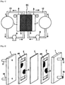
- a redox flow battery mainly includes outer tanks 6 and 7 for storing electrolytes (positive electrode electrolyte, negative electrode electrolyte), and an electrolytic cell EC.
- electrolytes positive electrode electrolyte, negative electrode electrolyte
- an electrolytic cell EC In the electrolytic cell EC, an ion-exchange membrane 3 is disposed between current collecting plates 1, 1 opposing each other.
- electrochemical energy conversion that is, charging and discharging, is performed on electrodes 5 incorporated in the electrolytic cell EC.
- a carbon material that has chemical resistance, electrical conductivity, and liquid permeability is used for the material of the electrode 5.
- an aqueous solution that contains metal ions whose valence is changed by oxidation-reduction is typically used as an electrolyte used for a redox flow battery.
- the type of electrolyte has been changed from a type in which a hydrochloric acid aqueous solution of iron is used for a positive electrode and a hydrochloric acid aqueous solution of chromium is used for a negative electrode, to a type in which a sulfuric acid aqueous solution of vanadium having high electromotive force is used for both electrodes, thereby increasing the energy density.
- the emitted electron passes through an external circuit and reduces V 5+ to V 4+ (ion containing oxygen in practice) in a three-dimensional electrode on the positive electrode side.
- V 5+ to V 4+ ion containing oxygen in practice
- SO 4 2- becomes insufficient in the negative electrode electrolyte
- SO 4 2- becomes excessive in the positive electrode electrolyte
- the charge balance can be maintained.
- a reaction reverse to that during discharging progresses.
- An electrode material for a redox flow battery is particularly required to have the following performances.
- Patent Literature 1 discloses a carbon material having a specific pseudo-graphite microcrystal structure with high crystallinity as an electrode material for Fe-Cr batteries that is capable of increasing the total energy efficiency of a battery.
- Patent Literature 1 discloses a carbon material that has pseudo-graphite microcrystals having an average ⁇ 002> interplanar spacing, determined by wide-angle X-ray analysis, of 3.70 ⁇ or smaller and an average crystallite size in the c-axis direction of 9.0 ⁇ or larger and that has a total acidic functional group amount of at least 0.01 meq/g.
- Patent Literature 2 discloses a carbon electrode material that is carbon fibers made from polyacrylonitrile-based fibers and is composed of a carbon having a pseudo-graphite crystal structure having a ⁇ 002> interplanar spacing, determined by wide-angle X-ray analysis, of 3.50 to 3.60 ⁇ and in which the number of oxygen atoms bound to the surface of the carbon is 10 to 25% of the number of carbon atoms thereon.
- Patent Literature 3 discloses an electrode that has a pseudo-graphite crystal structure having a ⁇ 002> interplanar spacing, determined by wide-angle X-ray analysis, of 3.43 to 3.60 ⁇ , a crystallite size in the c-axis direction of 15 to 33 ⁇ , and a crystallite size in the a-axis direction of 30 to 75 ⁇ , and in which the amount of acidic functional groups on the surface determined by XPS surface analysis is 0.2 to 1.0% of the total number of surface carbon atoms, and the number of surface-bound nitrogen atoms is not larger than 3% of the total number of surface carbon atoms.
- Patent Literature 4 discloses an electrode material that is composed of a carbon composite material in which carbon particulates having a crystal structure having a ⁇ 002> interplanar spacing, determined by wide-angle Xray analysis, of 3.43 to 3.70 ⁇ and an average primary particle diameter of not smaller than 30 nm and not larger than 5 ⁇ m are attached on carbon fibers, and the crystal structure of the carbon composite material has a ⁇ 002> interplanar spacing, determined by wide-angle X-ray analysis, of 3.43 to 3.60 ⁇ , a crystallite size in the c-axis direction of 15 to 35 ⁇ , and a crystallite size in the a-axis direction of 30 to 75 ⁇ .
- Patent Literature 4 indicates that, in the carbon composite material, the carbon fibers and the carbon particulates are preferably in close proximity or adhered to each other by an adhesive such as a phenol resin, and, when the adhesive is used, only the portions where the carbon fibers are originally in contact with each other can be fixed without excessively reducing the carbon fiber surfaces that are electrochemical reaction fields.
- Patent Literature 4 discloses a carbon fiber non-woven fabric obtained by immersing a non-woven fabric in a solution in which 5% by weight (Example 1) of carbon particulates (phenol resin) or 5% by weight (Examples 2 to 4) of a phenol resin is mixed, and then performing carbonization and dry oxidation.
- an electrolyte for example, Mn-Ti-based electrolyte
- manganese is used for a positive electrode
- chromium, vanadium, and/or titanium is used for a negative electrode
- Patent Literature 5 is proposed as an electrolyte that has a higher electromotive force than the above-described vanadium-based electrolyte and that is stably available at low cost.
- Mn ions are unstable in an aqueous solution, and the reaction rate is slow, so that the cell resistance is increased.
- the electrode material deteriorates since the oxidizing power of Mn ions (positive electrode charging liquid) generated during charging is very strong.
- the oxidation resistance to Mn ions is a characteristic required strongly for Mn-Ti-based redox flow batteries, and it has been found that the above problems cannot be sufficiently addressed by merely using the electrode materials for redox flow batteries described in Patent Literatures 2 to 4 described above, and it is difficult to achieve both high oxidation resistance and low resistance.
- the present invention has been made in view of the above circumstances, and an object of the present invention is to provide a carbon electrode material, for a redox flow battery, which is capable of decreasing cell resistance during initial charging and discharging while improving oxidation resistance to Mn ions (positive electrode charging liquid), particularly even when an Mn-Ti-based electrolyte is used, thereby improving battery energy efficiency.
- the present inventors have conducted studies in order to solve the above problems. As a result, the present inventors have found that the desired purpose can be achieved when graphite particles (B) are used as carbon particles, and carbon fibers (A) and a carbon material (C), which satisfy the following requirements, and a structure of the carbon fibers (A) are used, and have completed the present invention.
- the carbon electrode material of the present invention can achieve both high oxidation resistance and low resistance, and thus is particularly useful as an electrode material for a Mn-Ti-based redox flow battery.
- a resistance value that is substantially equal to the initial resistance value can be maintained, so that an electrode material having very excellent oxidation resistance can be provided.
- Such a carbon electrode material of the present invention is preferably used for flow-type and non-flow type batteries or a redox flow battery composited with lithium, a capacitor, and a fuel-cell system.
- the present inventors have diligently studied to particularly provide a carbon electrode material that is preferably used for Mn-Ti-based redox flow batteries in which Mn ions are used as a positive electrode active material and Ti ions are used as a negative electrode active material.
- Mn ions are used as a positive electrode active material
- Ti ions are used as a negative electrode active material.
- it is important for a Mn-Ti-based redox flow battery to have oxidation resistance to Mn ions but this point has not been taken into consideration for the electrode materials proposed so far. Therefore, as a result of the studies by the present inventors, it has been found that it is difficult to achieve both oxidation resistance and low resistance when the conventional electrode materials are used for a Mn-Ti-based redox flow battery.
- examples of particles exhibiting reaction activity in a redox flow battery include known carbon particles including: carbon blacks such as acetylene black (acetylene soot), oil black (furnace black, oil soot), and gas black (gas soot); and carbon particles such as graphitized soot, carbon fiber powder, carbon nanotubes (CNT), carbon nanofibers, carbon aerogel, mesoporous carbon, glassy carbon powder, activated carbon, graphene, graphene oxide, N-doped CNT, boron-doped CNT, fullerenes, petroleum coke, acetylene coke, and anthracite coke.
- carbon blacks such as acetylene black (acetylene soot), oil black (furnace black, oil soot), and gas black (gas soot)
- carbon particles such as graphitized soot, carbon fiber powder, carbon nanotubes (CNT), carbon nanofibers, carbon aerogel, mesoporous carbon, glass
- carbon particles such as carbon blacks, which have high reactivity and specific surface area and low crystallinity, are easily oxidized by a positive electrode charging liquid of manganese and cannot be used.
- carbon particles, such as CNT, which merely have high carbon crystallinity are merely used, sufficient reaction activity cannot be exhibited.
- these carbon particles are rare and expensive, and thus are not suitable as inexpensive electrode materials.
- the present inventors have decided to adopt a carbon material that has binding properties for binding both carbon fibers (A) and graphite particles (B) and that has high crystallinity and satisfies the following requirements (1) and (2).
- binding both carbon fibers (A) and graphite particles (B) means that the carbon material firmly binds the surfaces and insides of the carbon fibers and the graphite particles (including binding between the carbon fibers, and binding graphite particles to each other) to each other, and the surfaces of the graphite particles are exposed while the carbon fibers are covered with the carbon material as a whole of the electrode material.
- the carbon material that has bound the carbon fibers and the carbon particles is not in a coating state.
- “not in a coating state” means that the carbon material (C) does not form a webbed form such as a totipalmate form or a palmate form between the carbon fibers (A). This is because, in the case where the coating state is formed, the liquid permeability for an electrolyte deteriorates and the reaction surface area of the graphite particles cannot be effectively utilized.
- FIG. 3 shows an SEM photograph showing a state where both the carbon fibers (A) and the graphite particles (B) are bound.
- FIG. 3 is an SEM photograph (magnification: 100 times) of No. 1 (example of the present invention using a spunlace that satisfies the requirements of the present invention) in Table 2A in Example 2 described later. From FIG. 3 , it is found that the surfaces and insides of the carbon fibers (A) and the graphite particles (B) are firmly bound by the carbon material (C), and the surfaces of the graphite particles (B) are exposed while the carbon fibers (A) are covered with the carbon material (C).
- FIG. 4 and FIG. 5 are each an SEM photograph showing a state where both the carbon fibers (A) and the graphite particles (B) are not bound in the electrode material of the present invention.
- FIG. 4 is an SEM photograph (magnification: 100 times) of No. 15 (comparative example using a spunlace that does not satisfy the requirements of the electrode material of the present invention) in Table 2A in Example 2 described later.
- FIG. 5 is an SEM photograph (magnification: 100 times) of No. 10 (comparative example using carbon paper that does not satisfy the requirements of the present invention) in Table 2A in Example 2 described later.
- the content ratio of the carbon material (C) to the total content of the carbon fibers (A), the graphite particles (B), and the carbon material (C) is preferably increased, and is set to be, for example, not less than 20% by mass in the present invention.
- the carbon material (C) used in the present invention is different from the carbon material described in Patent Literature 4 described above. This is because, in Patent Literature 4, based on the idea that it is sufficient that only the part where carbon fibers and carbon particulates are originally in contact with each other is fixed (adhered), there is only recognition that it is sufficient that the carbon material to be used acts as a partial adhesive. Therefore, the content ratio of the carbon material is 14.4% by mass at most in Examples of Patent Literature 4.
- the carbon material (C) having such binding properties when used, the carbon material (C) strongly binds the carbon fibers (A) via the graphite particles (B), so that an efficient conductive path can be formed, and the action due to the addition of the graphite particles (B) described above is more effectively exerted, whereby both low resistance and high oxidation resistance can be achieved.
- the structure of the carbon fibers (A) used in the present invention satisfies an average curvature of not less than 1R and an average fiber diameter of 5 to 15 ⁇ m.
- the carbon electrode material of the present invention satisfies the following requirement (4).
- the number of oxygen atoms bound to the surface of the carbon electrode material is not less than 1.0% of the total number of carbon atoms on the surface of the carbon electrode material.
- oxygen atoms can be introduced into edge surfaces or defective structural portions of carbon.
- reactive groups such as a carbonyl group, a quinone group, a lactone group, and a free-radical oxide are generated from the introduced oxygen atoms on the surface of the electrode material. Therefore, these reactive groups make a large contribution to electrode reaction, thereby achieving sufficiently low resistance.
- the electrode material of the present invention is configured as described above, very high oxidation resistance can be achieved, and the reaction activity is also increased, so that an electrode having low resistance and long-life is obtained.
- the electrode material of the present invention is used as an electrode material for an electrolytic cell of a positive electrode manganese-based redox flow battery, it is possible to decrease the cell resistance during initial charging and discharging and improve the battery energy efficiency, so that it is possible to provide a carbon electrode material having excellent oxidation resistance to a positive electrode charging liquid.
- FIG. 2 is an exploded perspective view of a liquid-circulation type electrolytic cell that is preferably used in the present invention.
- an ion-exchange membrane 3 is disposed between two current collecting plates 1, 1 opposing each other, and liquid flow paths 4a and 4b for an electrolyte are formed by spacers 2 on both sides of the ion-exchange membrane 3 along the inner surfaces of the current collecting plates 1, 1.
- An electrode material 5 is disposed in at least one of the liquid flow paths 4a and 4b.
- a liquid inflow port 10 and a liquid outflow port 11 for an electrolyte are disposed at each current collecting plate 1.
- Electrode structure is threedimensionally formed
- the entire pore surface of the electrode material 5 can be used as an electrochemical reaction field to improve charging and discharging efficiency while transfer of electrons is ensured by the current collecting plate 1.
- the charging and discharging efficiency of the electrolytic cell is improved.
- the electrode material 5 of the present invention is an electrode material in which the carbon fibers (A) act as a base material and the graphite particles (B) are carried by the high-crystalline carbon material (C), and the above-described requirements (1) to (4) are satisfied.
- the details of the requirements are as follows.
- the carbon fibers used in the present invention mean fibers that are obtained by heating and carbonizing a precursor of organic fibers (details will be described later) and in which 90% or more in terms of mass ratio is composed of carbon (JIS L 0204-2).
- a precursor of organic fibers which is the raw material of the carbon fibers
- acrylic fibers such as polyacrylonitrile
- phenol fibers phenol fibers
- PBO fibers such as polyparaphenylene benzobisoxazole (PBO); aromatic polyamide fibers
- pitch fibers such as isotropic pitch fibers, anisotropic pitch fibers, and mesophase pitch
- cellulose fibers and the like can be used.
- acrylic fibers as the precursor of the organic fibers, acrylic fibers, phenol fibers, cellulose fibers, isotropic pitch fibers, and anisotropic pitch fibers are preferable, and acrylic fibers are more preferable, from the viewpoint of having excellent oxidation resistance, excellent strength and elasticity, etc.
- the acrylic fibers are not particularly limited as long as the fibers contain acrylonitrile as a main component, but the content of acrylonitrile in the raw material monomer forming the acrylic fibers is preferably not less than 95% by mass and more preferably not less than 98% by mass.
- the mass average molecular weight of the organic fibers is, but is not particularly limited to, preferably not less than 10000 and not larger than 100000, more preferably not less than 15000 and not larger than 80000, and further preferably not less than 20000 and not larger than 50000.
- the mass average molecular weight can be measured by a method such as gel permeation chromatography (GPC) or a solution viscosity method.
- the average fiber diameter of the carbon fibers is preferably 0.5 to 40 ⁇ m. If the average fiber diameter is smaller than 0.5 ⁇ m, the liquid permeability deteriorates. On the other than, if the average fiber diameter is larger than 40 ⁇ m, the three-dimensional structure becomes excessively coarse, resulting in an increase in cell resistance.
- the average fiber diameter is more preferably 3 to 20 ⁇ m in consideration of the balance between the liquid permeability and the three-dimensional structure.
- the average fiber length of the carbon fibers is preferably 30 to 100 mm. If the average fiber length is shorter than 30 mm, the entanglement of the fibers is insufficient, so that there is a problem that a structure form cannot be maintained at the time of oxidative deterioration, for example. On the other hand, if the average fiber length is longer than 100 mm, it becomes difficult for the fibers to be defibrated, so that there is a problem that the uniformity is impaired, for example.
- the average fiber length is more preferably 40 to 80 mm.
- a structure of the above carbon fibers (hereinafter, sometimes referred to as a fiber structure) is used as a base material.
- the use of the fiber structure improves the strength and facilitates handling and processability.
- the fiber structure satisfies an average curvature of not less than 1R and an average fiber diameter of 5 to 15 ⁇ m.
- the following has been found for the first time.
- the structure form can be maintained by the three-dimensional structure, so that a resistance substantially equal to the initial resistance value can be maintained, and fewer particles fall off at the time of oxidative deterioration, whereby an electrode material having very excellent oxidation resistance can be provided (see the cells for "overall cell resistance” at "oxidation resistance test” in Table 2 shown below).
- the structure form cannot be maintained. Therefore, the space maintained by the structure form disappears, the liquid flowability in the cell significantly deteriorates, and the battery performance significantly deteriorates.
- the larger the curvature R that is, the smaller the curvature radius r), the higher the degree of bending.
- SEM scanning electron microscope
- the average curvature is preferably larger, and is preferably not less than 5R, and more preferably not less than 10R. However, in consideration of defibration of fibers, etc., in general, the average curvature is preferably not larger than 200R.
- the above “fiber structure having an average curvature of not less than 1R” means that most of the fibers forming the fiber structure are curved or curled.
- the above “fiber structure having an average curvature R of not less than 1” can also be said to be a three-dimensional structure in which the fibers exist in the thickness direction when a cross-section in the thickness direction (cross-section perpendicular to the fiber length direction) of the fiber structure is observed with a scanning electron microscope.
- papers such as carbon paper linear fibers are connected to each other, and when such a paper is observed with a microscope by the same method as described above, the average curvature R is zero, and the requirements of the present invention are not satisfied.
- the above papers are also different from the fiber structure used in the present invention, in that the papers are two-dimensional structures in which fibers do not exist in the thickness direction but exist only in the fiber length direction.
- non-woven fabrics, felt, knitted fabrics, woven fabrics, and special woven/knitted fabrics which are made of carbon fibers are more preferable from the viewpoint of handleability, processability, productivity, etc.
- Non-woven fabrics are more preferable.
- non-woven fabrics are defined in JIS L 0222, and examples thereof include spunbond non-woven fabrics, spunlace non-woven fabrics, needlepunched non-woven fabrics, resin-bonded non-woven fabrics, and thermal-bonded non-woven fabrics, depending on the difference in manufacturing methods such as entanglement, fusion, and bonding.
- the average fiber diameter of the fiber structure is 5 to 15 ⁇ m. If the average fiber diameter is smaller than the above lower limit, the strength of the structure form is decreased. On the other hand, if the average fiber diameter is larger than the above upper limit, the uniformity of the structure form is impaired.
- the average fiber diameter of the structure is preferably 7 to 10 ⁇ m.
- the carbon fibers are obtained by heating and carbonizing the precursor of the organic fibers.
- the "heating and carbonizing” preferably includes at least a flameproofing step and a carbonizing (calcining) step.
- the carbonizing step does not necessarily have to be performed after the flameproofing step as described above.
- the carbonizing step may be performed after flameproofed fibers are impregnated with the graphite particles and the carbon material as in EXAMPLES described later. In this case, the carbonizing step after the flameproofing step can be omitted.
- the above flameproofing step means a step of heating the precursor of the organic fibers under an air atmosphere preferably at a temperature of not lower than 180°C and not higher than 350°C to obtain flameproofed organic fibers.
- the heating temperature is more preferably not lower than 190°C and further preferably not lower than 200°C.
- the heating temperature is preferably not higher than 330°C and more preferably not higher than 300°C.
- the organic fibers may be thermally contracted, and the molecular orientation thereof may be broken, to reduce the electrical conductivity of the carbon fibers. Therefore, the organic fibers are preferably flameproofed under a strained or drawn state, and more preferably flameproofed under a strained state.
- the carbonizing step means a step of heating the flameproofed organic fibers obtained as described above, under an inert atmosphere (preferably, under a nitrogen atmosphere) preferably at a temperature of not lower than 1000°C and not higher than 2000°C to obtain the carbon fibers.
- the heating temperature is more preferably not lower than 1100°C and further preferably not lower than 1200°C.
- the heating temperature is more preferably not higher than 1900°C.
- the heating temperature in the carbonizing step can be selected according to the type of the organic fibers as a raw material.
- the heating temperature is preferably not lower than 800°C and not higher than 2000°C, and more preferably not lower than 1000°C and not higher than 1800°C.
- the above flameproofing step and carbonizing step are preferably continuously performed.
- a temperature rising rate is preferably not larger than 20°C/minute and more preferably not larger than 15°C/minute when the temperature rises from the flameproofing temperature to the carbonizing temperature.
- the lower limit of the temperature rising rate is preferably not less than 5°C/minute in consideration of the mechanical properties and the like.
- the electrode material of the present invention satisfies a condition that Lc(C)/Lc(A) is not less than 1.0 when Lc(A) and Lc(C) represent crystallite sizes, in the c-axis direction, obtained by X-ray diffraction in the carbon fibers (A) and the carbon material (C), respectively, as defined in the above-described (2). Therefore, in the present invention, Lc(A) in the carbon fibers (A) is not particularly limited as long as the above-described (2) is satisfied, but Lc(A) is preferably 1 to 15 nm and more preferably 1 to 10 nm.
- Lc(A) is further preferably 2 to 10 nm. A method for measuring Lc(A) will be described in detail later in Examples.
- the graphite particles are necessary to increase the change in valence (reactivity) due to oxidation-reduction to achieve high oxidation resistance.
- the graphite particles used in the present invention have Lc(B) of preferably not less than 35 nm and more preferably not less than 37 nm. Accordingly, a carbon edge surface serving as a reaction field can be exposed without excess or deficiency, so that it is possible to achieve both low resistance and high oxidation resistance.
- the upper limit of the above value is not particularly limited from the above viewpoint, but, in general, is preferably not larger than 50 nm in consideration of the balance between oxidation resistance and low resistance, etc.
- Graphite particles are generally roughly classified into natural graphite and artificial graphite.
- natural graphite include scaly graphite, flaky graphite, earthy graphite, spheroidal graphite, and laminate graphite
- artificial graphite include expanded graphite and graphite oxide.
- any of natural graphite and artificial graphite can be used, but among them, graphite oxide, scaly graphite, flaky graphite, earthy graphite, spheroidal graphite, laminate graphite, and expanded graphite are preferable since these graphites have a carbon edge surface as a reaction field.
- scaly graphite, laminate graphite, spheroidal graphite, and expanded graphite are more preferable since not only the carbon edge surface is exposed very greatly to achieve low resistance, but also the cost is low and the amount of resources is abundant.
- These scaly graphite, laminate graphite, spheroidal graphite, and expanded graphite may be added alone, or two or more of these graphites may be mixed and used.
- scaly graphite means one having leaf-like appearance.
- Scaly graphite is different from flaky graphite (which is lumpy in shape and is sometimes referred to as lump graphite).
- the particle diameter of the graphite particles (B) used in the present invention is preferably not less than 1 ⁇ m and more preferably not less than 3 ⁇ m. If the particle diameter is less than 1 ⁇ m, the ratio of the graphite particles buried in the carbon material is increased, and a small amount of the graphite particles appear on the surface of the carbon material, so that the specific surface area of the carbon material is excessively increased. As a result, the effect of improving oxidation resistance by the addition of the graphite particles (B) is not effectively exhibited, and the oxidation resistance tends to decrease.
- the “particle diameter” means an average particle diameter (D50) as a median diameter at 50% in a particle diameter distribution obtained by a dynamic light scattering method or the like.
- D50 average particle diameter
- the graphite particles a commercially available product may be used. In this case, the particle diameter shown in the catalog can be adopted.
- the graphite particles used in the present invention are contained in a content of preferably not less than 20% and more preferably not less than 25% as a mass ratio to the total content of the carbon fibers (A) and graphite particles (B), which are described above, and the carbon material (C) described below. Accordingly, the above effect by the addition of the graphite particles is effectively exhibited, and in particular, the oxidation resistance is improved.
- the upper limit of the content is not particularly limited from the viewpoint of oxidation resistance, etc., but, in general, is not larger than 60% in consideration of the balance between oxidation resistance and low resistance, etc.
- the content of the carbon fibers (A) used for calculating the above content is the content of a structure such as a non-woven fabric in the case where the structure is used as the base material.
- the mass ratio of the carbon material (C) described below to the graphite particles (B) is preferably not less than 0.2 and not larger than 3.0, and more preferably not less than 0.3 and not larger than 2.5. If the above ratio is less than 0.2, more graphite particles fall off, so that, in particular, the effect of improving oxidation resistance by the addition of the graphite is not effectively exhibited. On the other hand, if the above ratio is larger than 3.0, the carbon edge surfaces of the graphite particles, which are reaction fields, are covered, so that desired low resistance is not achieved.
- the BET specific surface area, of the graphite particles (B) used in the present invention, obtained from a nitrogen adsorption amount is preferably 3 to 20 m 2 /g and more preferably 5 to 15 m 2 /g. If the BET specific surface area is less than 3 m 2 /g, the exposure of the edge surfaces of the graphite particles (B) is reduced, so that the desired low resistance is not achieved. On the other hand, if the BET specific surface area is equal to or larger than 20 m 2 /g, the specific surface area is excessively increased, so that the effect of improving oxidation resistance by the addition of the graphite particles (B) is not effectively exhibited, and the oxidation resistance tends to decrease.
- the "BET specific surface area obtained from a nitrogen adsorption amount” means a specific surface area calculated from the amount of gas molecules adsorbing when gas molecules are caused to adsorb to solid particles.
- the carbon material used in the present invention is added as a binding agent (binder) for firmly binding carbon fibers and graphite particles, which cannot be intrinsically bound to each other, and has an effect of protecting carbon fibers which are inferior in oxidation resistance.
- Lc(C) needs to satisfy not less than 10 nm when Lc(C) represents the crystallite size, in the c-axis direction, obtained by X-ray diffraction in the carbon material (C) as defined in the above (1)
- Lc(C)/Lc(A) needs to satisfy not less than 1.0 when Lc(A) represents the crystallite size, in the c-axis direction, obtained by X-ray diffraction in the carbon fibers (A) as defined in the above (2).
- Lc(C) is preferably not less than 10 nm and more preferably not less than 12 nm.
- the upper limit of Lc(C) is not particularly limited from the above viewpoint, but, in general, is preferably not larger than 40 nm in consideration of achievement of both oxidation resistance and low resistance, etc.
- the ratio Lc(C)/Lc(A) is less than 1.0, the above effect is not effectively exhibited.
- the above ratio is preferably not less than 2 and more preferably not less than 3.
- the above ratio is larger than 10, it is difficult to achieve low resistance.
- the above ratio is preferably not larger than 8.
- the carbon material (C) used in the present invention is contained in a content of preferably not less than 20% and more preferably not less than 30% as a mass ratio to the total content of the carbon fibers (A) and graphite particles (B), which are described above, and the carbon material (C).
- a content ratio of the carbon material is increased as described above, both the carbon fibers and the graphite particles can be sufficiently bound, so that the effect by the addition of the carbon material is effectively exhibited, and in particular, the oxidation resistance is improved.
- the upper limit of the content is not particularly limited from the viewpoint of oxidation resistance, etc., but, in general, is preferably not larger than 60% in consideration of liquid flow pressure loss, etc.
- the upper limit of the content is more preferably not larger than 50%.
- the type of the carbon material (C) used in the present invention may be any type when the carbon fibers (A) and the graphite particles (B) can be bound. Specifically, the type of the carbon material (C) is not particularly limited as long as binding properties are exhibited during carbonizing when the electrode material of the present invention is produced.
- pitches such as coal-tar pitch and coal-based pitch
- resins such as phenol resin, benzoxazine resin, epoxide resin, furan resin, vinylester resin, melamineformaldehyde resin, urea-formaldehyde resin, resorcinol-formaldehyde resin, cyanate ester resin, bismaleimide resin, polyurethane resin, and polyacrylonitrile; furfuryl alcohol; and rubber such as acrylonitrile-butadiene rubber.
- pitches such as coal-tar pitch and coal-based pitch
- resins such as phenol resin, benzoxazine resin, epoxide resin, furan resin, vinylester resin, melamineformaldehyde resin, urea-formaldehyde resin, resorcinol-formaldehyde resin, cyanate ester resin, bismaleimide resin, polyurethane resin, and polyacrylonitrile
- furfuryl alcohol and rubber such as
- pitches such as coal-tar pitch and coal-based pitch which are easily crystallizable are preferable since the target carbon material (C) can be obtained at a low calcining temperature.
- Polyacrylonitrile resin is also preferably used since the target carbon material (C) can be obtained when the calcining temperature is increased. Pitches are particularly preferable.
- a harmful effect generation of formaldehyde and formaldehyde odor at room temperature
- a harmful effect generation of formaldehyde and formaldehyde odor at room temperature
- a phenol resin is used as an adhesive. Therefore, in addition to the above-described harmful effect being exerted, for example, equipment for controlling the concentration of formaldehyde at a working site such that the concentration of formaldehyde is not higher than a control concentration needs to be additionally provided, and this is disadvantageous from the viewpoint of cost and workability.
- pitches that are particularly preferably used will be described in detail.
- the content ratio of a mesophase liquid crystal phase
- the content ratio of a mesophase can be controlled by an infusibilizing temperature and time. If the content of the mesophase is small, a pitch in a melted state is obtained at a relatively low temperature or a pitch in a liquid state is obtained at room temperature. On the other hand, if the content ratio of the metaphase is large, the pitch is melted at a high temperature, resulting in a high carbonization yield.
- the content ratio of the mesophase is preferably larger (that is, carbonization rate is higher), and is, for example, preferably not less than 30% and more preferably not less than 50%. Accordingly, fluidity at the time of melting is reduced, and the carbon fibers can be bound to each other through the graphite particles without excessively covering the surfaces of the graphite particles.
- the upper limit of the content ratio is, for example, preferably not larger than 90% in consideration of exhibition of binding properties, etc.
- the melting point of the pitch is preferably not lower than 100°C and more preferably not lower than 200°C. Accordingly, in addition to the above effect being obtained, odor in the impregnating process can be reduced, so that such a melting point is also preferable from the viewpoint of processability.
- the upper limit of the melting point is, for example, preferably not higher than 350°C in consideration of exhibition of binding properties, etc.
- the electrode material of the present invention satisfies the condition that the number of oxygen atoms bound to the surface of the carbon electrode material is not less than 1.0% of the total number of carbon atoms on the surface of the carbon electrode material.
- the ratio of the number of bound oxygen atoms to the total number of carbon atoms is sometimes abbreviated as O/C.
- the O/C can be measured by surface analysis such as X-ray photoelectron spectroscopy (XPS) or fluorescent X-ray analysis.
- the electrode reaction velocity can be significantly increased, thereby achieving low resistance.
- the hydrophilicity can be enhanced by controlling the O/C, so that a water flow rate (preferably, not less than 0.5 mm/sec) of the electrode material as described later can be assured.
- the electrode reaction rate at the time of discharging is decreased, so that the electrode reaction activity cannot be enhanced. As a result, the resistance is increased.
- the electrode reaction activity in other words, voltage efficiency
- the electrode material having a lot of oxygen atoms bound to the surface thereof as described above are not clear, a lot of oxygen atoms on the surface are considered to effectively act on affinity between the carbon material (C) and the electrolyte, emission and reception of electrons, desorption of complex ions from the carbon material, complex exchange reaction, etc.
- the electrode material of the present invention has excellent hydrophilicity.
- the hydrophilicity can be confirmed by a water flow rate when a water droplet is dropped after the electrode material is oxidized in a dry process.
- the water flow rate of the electrode material of the present invention is preferably not less than 0.5 mm/sec. Accordingly, the affinity for the electrolyte can be determined as being sufficient. The higher the water flow rate of the electrode material is, the better the electrode material is.
- the water flow rate is more preferably not less than 1 mm/sec, further preferably not less than 5 mm/sec, and further preferably not less than 10 mm/sec.
- a surface area A having a pore diameter of 0.1 to 10 ⁇ m preferably satisfies 0.3 to 3.5 m 2 /g. According to the results of the studies by the present inventors, it has been found that the surface area A having a pore diameter in the above range has a high correlation with the effect of decreasing resistance at a state of charge of 30% in a low charging depth region where the active material is insufficient, and when the surface area A is increased, a good effect of decreasing resistance is exhibited in the low charging depth region (see the cells for overall cell resistance at SOC of 30% described later).
- the reaction of the redox flow battery occurs only on the surface of the electrode with which the electrolyte comes into contact. Therefore, in the region where the pore diameter is smaller than the above range and is, for example, several nanometers or smaller, entry of the active material is blocked due to the influence of surface tension with the electrolyte, so that it is considered that the surface area in this region is unlikely to contribute to the reaction. On the other hand, it is considered that, in the region where the pore diameter is 0.1 to 10 ⁇ m, which is the target in the present invention, the electrolyte is efficiently brought into contact with the electrode surface portion, and particularly, the reaction in the low charging depth region where the active material is insufficient is smoothly carried out.
- the pore diameter is less than 0.1 ⁇ m, the proportion, in the low charging depth region, which contributes to the reaction may be decreased. On the other hand, if the pore diameter is larger than 10 ⁇ m, the surface area in the same space tends to be insufficient, so that such a pore diameter is not preferable.
- the pore diameter is more preferably 0.1 to 5 ⁇ m.
- the surface area A is less than 0.3 m 2 /g, it is difficult to achieve the desired effect.
- the surface area A is larger than 3.5 m 2 /g, the durability tends to deteriorate.
- the surface area A is more preferably 0.5 to 3.3 m 2 /g and further preferably 1.0 to 3.0 m 2 /g.
- the ratio of the surface area A to the total surface area is preferably not less than 50%. If the ratio is less than 50%, it is difficult to achieve the effect of decreasing resistance in the above-described low charging depth region, and the number of starting points of oxidative deterioration is increased, so that the durability deteriorates even if the performance is the same.
- the ratio is more preferably not less than 60%.
- the upper limit of the ratio is not particularly limited from the above viewpoint, but, in general, is preferably not larger than 80% in consideration of the occupied volume for achieving the above surface area, etc.
- Examples of the method for obtaining the above surface area A include the following first to fourth methods.
- the first method is a method of appropriately controlling the weight ratio of the graphite particles (B) to the carbon material (C).
- the weight ratio of graphite particles (B)/carbon material (C) is preferably 3/1 to 1/3. If the weight ratio is less than 3/1, the binding properties by the carbon material (C) are insufficient, and falling-off of powder is increased, so that such a ratio is not preferable. On the other hand, if the weight ratio is larger than 1/3, it becomes difficult to obtain the desired surface area A.
- the average particle diameter of the graphite particles (B) is preferably 1 to 30 ⁇ m and more preferably 5 to 20 ⁇ m.
- the second method is to increase the melting point of the carbon material (C) and control the particle diameter of the carbon material (C). According to this method, carbonization after the carbon material (C) is melted rapidly progresses, and fluidity of the carbon material (C) is suppressed, so that the predetermined surface area A is obtained without closing pores having a pore diameter of 0.1 to 10 ⁇ m, which is the target.
- the melting point of the carbon material (C) is preferably not lower than 100°C and more preferably not lower than 200°C. Accordingly, in addition to the above effect being obtained, odor in the impregnating process can be reduced, so that such a melting point is also preferable from the viewpoint of processability.
- the upper limit of the melting point of the carbon material (C) is, for example, preferably not higher than 350°C in consideration of exhibition of binding properties, etc. Furthermore, in the case where such a carbon material (C) is used, the average particle diameter of the carbon material (C) is preferably controlled to 1 to 40 ⁇ m. If the average particle diameter of the carbon material (C) is less than 1 ⁇ m, the pores having a pore diameter of 0.1 to 10 ⁇ m, which is the target, may be closed. On the other hand, if the average particle diameter of the carbon material (C) is larger than 40 ⁇ m, the contact surface with the graphite particles (B) is reduced, so that the binding force is insufficient.
- the third method is to infusibilize the carbon material (C). Specifically, when the carbon material (C) is heated at 200 to 350°C under an oxygen atmosphere, after the carbon material (C) is once melted, the condensation reaction of the carbon precursor in a green pitch coke progresses to infusibilize the carbon material (C). Accordingly, the fluidity when the carbon material (C) is melted is suppressed without impairing the binding properties with the graphite particles (B) or the binding properties with the carbon fibers (A), and the predetermined surface area A can be obtained without closing the pores having a pore diameter of 0.1 to 10 ⁇ m, which is the target.
- the heating temperature for the carbon material (C) is preferably not lower than 250°C and more preferably not lower than 300°C. In the above method, the carbon material (C) that has been infusibilized and ground in advance may be used.
- the fourth method is a method of adding a material that almost disappears during carbonization. Accordingly, desired pores can be formed.
- the above material include cellulose, polyethylene, and polypropylene.
- a material in a particle state having an average particle diameter of 5 to 30 ⁇ m or a fibrous material having an average fiber diameter of 10 to 20 ⁇ m is preferably used.
- the weight per unit area of the electrode material of the present invention is preferably 50 to 500 g/m 2 and more preferably 100 to 400 g/m 2 in the case where the thickness (hereinafter, referred to as "spacer thickness") of the spacer 2 between the current collecting plate 1 and the ion-exchange membrane 3 is 0.3 to 3 mm.
- spacer thickness the thickness of the spacer 2 between the current collecting plate 1 and the ion-exchange membrane 3 is 0.3 to 3 mm.
- a non-woven fabric or paper having one face flattened is more preferably used as the base material.
- Any known flattening method can be applied. Examples of the flattening method include a method of applying a slurry to one face of the carbon fibers and drying the slurry thereon, and a method of impregnation and drying on a smooth film formed of PET or the like.
- the thickness of the electrode material of the present invention is preferably at least larger than the spacer thickness.
- the thickness of the electrode material is preferably 1.5 to 6.0 times the spacer thickness.
- the ion-exchange membrane 3 may be pierced due to compression stress of a sheetshaped object. Therefore, as the electrode material of the present invention, a material having a compression stress of not larger than 9.8 N/cm 2 is preferably used.
- two or three layers of the electrode material of the present invention may be stacked and used in order to adjust the compression stress or the like according to the weight per unit area and/or the thickness of the electrode material of the present invention.
- another form of an electrode material may also be used in combination.
- the BET specific surface area, of the electrode material of the present invention, obtained from a nitrogen adsorption amount is preferably 1.0 to 8 m 2 /g and more preferably 1.5 to 6 m 2 /g. If the BET specific surface area is less than 1.0 m 2 /g, the exposure of the edge surfaces of the graphite particles (B) is reduced, so that desired low resistance is not achieved. On the other hand, if the BET specific surface area is larger than 8 m 2 /g, the specific surface area is excessively increased, so that the effect of improving oxidation resistance by the addition of the graphite particles (B) is not effectively exhibited, and the oxidation resistance tends to decrease.
- the electrode material of the present invention can be produced through a carbonizing step, a graphitization step, and an oxidization step after the carbon fibers (base material) are impregnated with the graphite particles and a precursor (before carbonized) of the carbon material. In each step, any known method can be applied.
- the carbon fibers are impregnated with the graphite particles and the precursor of the carbon material.
- Any known method can be adopted for impregnating the carbon fibers with the graphite particles and the precursor of the carbon material.
- An example of such a method is a method of heating and melting the above carbon material precursor, dispersing the graphite particles in the obtained melt, immersing the carbon fibers in the melted dispersion liquid, and then cooling the carbon fibers to room temperature.
- a method of dispersing the above carbon material precursor and the graphite particles in a solvent such as an alcohol or water to which a binder (provisional adhesive) such as polyvinyl alcohol which disappears during carbonization is added, immersing the carbon fibers in the dispersion liquid, and then heating and drying the carbon fibers, as described later in Examples, can be used.
- the excess liquid of the above melted dispersion liquid or dispersion liquid in which the carbon fibers have been immersed can be removed by, for example, a method in which the excess dispersion liquid provided when the carbon fibers are immersed in the dispersion liquid is squeezed through nip rollers having a predetermined clearance, or a method in which the surface of the excess dispersion liquid provided when the carbon fibers are immersed in the dispersion liquid is scraped by a doctor blade or the like.
- drying is performed under an air atmosphere at, for example, 80 to 150°C.
- the carbonizing step is performed for calcining the product obtained by the impregnation in the above step. Accordingly, the carbon fibers are bound to each other through the graphite particles.
- decomposed gas generated during carbonization is sufficiently removed.
- heating is preferably performed at a temperature of not lower than 800°C and not higher than 2000°C under an inert atmosphere (preferably, under a nitrogen atmosphere).
- the heating temperature is preferably not lower than 1000°C, further preferably not lower than 1200°C, and even more preferably not lower than 1300°C, and is more preferably not higher than 1500°C and further preferably not higher than 1400°C.
- the carbonizing treatment after flameproofing the fibers may be omitted. That is, the method for producing the electrode material of the present invention is mainly classified into the following method 1 and method 2.
- the method 1 carbonization is performed twice and the processing cost is thus increased.
- a sheet used as the electrode material is unlikely to be influenced by a difference in a volume shrinkage rate
- the obtained sheet is advantageously unlikely to be deformed (warped).
- the carbonizing step is performed only once and the processing cost can thus be reduced.
- the obtained sheet is likely to be deformed due to a difference in a volume shrinkage rate during carbonization of each material. Whether to adopt either of the above methods 1 and 2 may be determined as appropriate in consideration of these points.
- the graphitization step is performed in order to sufficiently increase the crystallinity of the carbon material and achieve high oxidation resistance. Furthermore, after the carbonizing step, heating is preferably performed under an inert atmosphere (preferably, under a nitrogen atmosphere) at a temperature that is not lower than 1800°C and higher than the heating temperature in the carbonizing step, and more preferably at a temperature of not lower than 2000°C. The upper limit of the temperature is preferably not higher than 3000°C in consideration of the load on the equipment, etc.
- the method in Patent Literature 4 described above is different from the method for producing the electrode material according to the present invention, in that the graphitization step is not performed. Therefore, the electrode material in Patent Literature 4 does not satisfy the requirement [Lc of the carbon material (C) is not less than 10 nm] for the electrode material of the present invention.
- the oxidization step is further performed, whereby oxygen functional groups such as a hydroxyl group, a carbonyl group, a quinone group, a lactone group, and a free-radical oxide are introduced into the surface of the electrode material.
- oxygen functional groups such as a hydroxyl group, a carbonyl group, a quinone group, a lactone group, and a free-radical oxide are introduced into the surface of the electrode material.
- a dry oxidization step means a step of heating (oxidizing), for example, at a temperature of not lower than 500°C and not higher than 900°C under an air atmosphere.
- the heating temperature is more preferably not lower than 600°C and further preferably not lower than 650°C.
- the heating temperature is more preferably not higher than 800°C and further preferably not higher than 750°C.
- the mass yield of the electrode material obtained from the masses before and after the oxidization is preferably adjusted to be not lower than 90% and not higher than 96%.
- This mass yield can be adjusted by, for example, a method of adjusting the treatment time or temperature in the dry air oxidization as appropriate.
- Lc(A) of the carbon fibers Lc(B) of the graphite particles, and Lc(C) of the carbon material were measured as follows.
- the carbon fibers, the graphite particles, and the carbon material (individual elements) used in the examples were sequentially subjected to the same heating process as in Example 2, and finally processed samples were used for the measurement.
- the carbon crystallinity is influenced dominantly by thermal energy imparted to the sample, and the crystallinity of Lc is determined by a thermal history of the sample at the highest temperature.
- a graphene laminate structure formed in the graphitization step may be broken depending on a degree of the succeeding oxidization, and the crystallinity may be reduced due to generation of a defective structure, etc. Therefore, the finally processed samples were used.
- Each individual element sample obtained as described above was ground by using an agate mortar until the particle diameter became about 10 ⁇ m.
- About 5% by mass of X-ray standard high-purity silicon powder as an internal standard substance was mixed with the ground sample, and a sample cell was filled therewith, and a wide angle X-ray measurement was performed by diffractometry using CuKa rays as a ray source.
- peaks were separated from a chart obtained by the wide-angle X-ray measurement to calculate the respective Lc values. Specifically, a peak having a top in a range where twice (2 ⁇ ) a diffraction angle ⁇ was 26.4° to 26.6° was set as the graphite particles (B), and a peak having a top in a range where twice (2 ⁇ ) the diffraction angle ⁇ was 25.7° to 26.2° was set as the carbon material (C).
- a peak shape as a sine wave was determined from each peak top, and a peak shape as a sine wave was thereafter determined from a foot portion appearing near 24.0° to 25.0°, and set as the carbon fibers (A).
- both peak tops were separated from each other by determining a peak shape as a sine wave from a foot portion appearing near 24.0° to 26.0°.
- Lc of each of the carbon fibers (A), the graphite particles (B), and the carbon material (C) was calculated by the following method based on the three peaks separated by the above method.
- wavelength ⁇ 1.5418 ⁇
- structure factor k 0.9
- ⁇ represents the half width of a ⁇ 002> diffraction peak
- ⁇ represents a ⁇ 002> diffraction angle
- the surface of the carbon electrode material was observed with a scanning electron microscope (SEM) at a magnification of 100 times.
- SEM scanning electron microscope
- the radius of the arc was defined as a curvature radius r (measured in millimeter), and 1/r was calculated and defined as a curvature R.
- the same measurement was performed at 5 locations in total, and the average value of the measurements was calculated to obtain an average curvature R.
- a 5801MC device available from ULVAC-PHI, Inc. was used for measurement by X-ray photoelectron spectroscopy abbreviated as ESCA or XPS.
- the sample was fixed onto a sample holder by a Mo plate, exhaustion was sufficiently performed in a preliminary exhaustion chamber, and the sample was thereafter put into a chamber in a measurement chamber.
- Monochromated AlKa rays were used as a ray source, output was set at 14 kV and 12 mA, and the degree of vacuum in the device was set to 10 -8 torr.
- the ratio of the number of oxygen atoms bound to the surface to the total number of carbon atoms on the surface was calculated as a percentage (%), to calculate O/C.
- Each electrode material obtained in a method described below was cut out so as to have a 2.7 cm side in the up-down direction (liquid flowing direction), a 3.3 cm side in the width direction, and an electrode area of 8.91 cm 2 , and was introduced only to the positive electrode side. At this time, the number of electrode materials was adjusted such that the weight per unit area within the cell was 230 to 350 g/m 2 .
- Two electrode materials produced as described below were stacked on the negative electrode side to assemble the cell shown in FIG. 1 .
- a Nafion 212 membrane was used for the ion-exchange membrane, and the spacer thickness was set to 0.5 mm.
- the overall cell resistance ( ⁇ cm 2 ) in the following equations (1) and (2) was calculated from a voltage curve of the 10th cycle at 144 mA/cm 2 in a voltage range of 1.55 to 1.00 V.
- a plain weave cloth (thickness: 1.0 mm, weight per unit area: 600 g/m 2 ) made of polyacrylonitrile fibers having an average fiber diameter of 16 ⁇ m was heated at 300°C under an air atmosphere to flameproof the cloth, and the cloth was calcined at 1000°C under a nitrogen atmosphere for 1 hour. Then, the cloth was heated at 600°C under an air atmosphere for 8 minutes, and then calcined at 1800°C under a nitrogen atmosphere for 1 hour. Furthermore, the cloth was treated at 700°C under an air atmosphere for 15 minutes, thereby obtaining an electrode material, for a negative electrode, having a weight per unit area of 152 g/m 2 and a thickness of 0.73 mm.
- Part 1 For the electrode material, two types of oxidation resistance were evaluated as described below.
- Part 2 evaluates that the resistance does not easily increase even if the weight loss due to oxidative deterioration progresses, and thus Part 2 can be said to be a more advanced test for evaluating oxidation resistance as compared with Part 1.
- the electrode material was immersed in an excessive amount of the charging liquid for a longer time.
- the weight-reduced electrode material was washed with the uncharged electrolyte, then washed with 2.5 M sulfuric acid, and washed with pure water until the washing liquid became neutral.
- the washed electrode material was dried at 120°C overnight, the overall cell resistance at SOC of 50% was then measured in the same manner as in the above (6), and the oxidation resistance was evaluated.
- the BET specific surface area of the sample was measured using a specific surface area/pore distribution measuring device, Gemini 2375 (manufactured by Micromeritics Instrument Corporation). Specifically, the adsorption amount of nitrogen gas at the boiling point (-195.8°C) of liquid nitrogen was measured in a range of relative pressure of 0.02 to 0.95, and an adsorption isotherm of the sample was created. Based on the results in the range of relative pressure of 0.02 to 0.15, the BET specific surface area per weight (unit: m 2 /g) was obtained by the BET method.
- Measurement was performed under the following conditions using a pore distribution measuring device [AutoPore IV9520 (manufactured by SHIMADZU CORPORATION)].
- a sample was cut into a strip of about 12.5 mm x 25 mm, about 0.04 to 0.15 g of the sample was taken in a 5 mL powder cell (stem volume: 0.4 mL), and measurement was performed under the condition of an initial pressure of about 3.7 kPa (about 0.5 psia, equivalent to a pore diameter of about 340 ⁇ m).
- the mercury parameters were set to a mercury contact angle of 130 degrees and mercury surface tension of 485 dynes/cm which are the device default, and the volume of pores having a pore diameter 0.1 to 10 ⁇ m was measured. From this value, a surface area A was calculated by using the surface area of a cylinder as a model
- a to E are each graphite defined in the present invention
- A, B, and C are each scaly graphite
- D is laminate graphite
- E is spheroidal graphite.
- F is scaly graphite having a small Lc
- G is scaly graphite having a particle diameter of less than 1 ⁇ m and a small Lc.
- A' is graphite obtained by grinding A for 6 hours through bead milling with a LABSTAR Mini machine manufactured by Ashizawa Finetech Ltd., and is an example that has a small Lc.
- a and b are carbon blacks.
- electrode materials were produced as follows, and various items thereof were measured.
- an electrode material was produced as follows, using a spunlace non-woven fabric made of flameproofed polyacrylonitrile fibers, as a structure of carbon fibers, C in Table 1 (example satisfying the requirements of present invention) as graphite particles, and a pitch, which is coal tar pitch MCP250 (melting point: 250°C, particle diameter: 10 ⁇ m) manufactured by JFE Chemical Corporation, as a carbon material.
- RHEODOL TW-L120 nonionic surfactant
- Kao Corporation 1.8% of polyvinyl alcohol (provisional adhesive), 14% of MCP250 manufactured by JFE Chemical Corporation (carbon material), and 9.8% of C in Table 1 as graphite powder were added to ion-exchanged water and stirred with a mechanical stirrer for 1 hour to prepare a dispersion liquid.
- a spunlace non-woven fabric made of polyacrylonitrile fibers (manufactured by SHINWA Corporation, weight per unit area: 100 g/m 2 , average curvature: 40R, average fiber diameter: 20 ⁇ m, average fiber length: 80 mm, thickness: 0.81 mm) was immersed in the dispersion liquid thus obtained, and then passed through nip rollers to remove the excess dispersion liquid.
- the non-woven fabric was dried at 150°C under an air atmosphere for 20 minutes, then carbonized (calcined) at 1000°C under a nitrogen atmosphere for 1 hour, and further graphitized at 2000°C for 1 hour. After the graphitization, oxidation was performed at 700°C under an air atmosphere for 20 minutes, to obtain an electrode material (No. 1) having a thickness of 0.66 mm and a weight per unit area of 184.0 g/m 2 .
- the average fiber diameter of the fiber structure in the above No. 1 was 10 ⁇ m due to shrinkage during carbonization (see Table 2).
- An electrode material No.2 (a thickness of 0.44 mm, a weight per unit area of 104.0 g/m 2 ) was produced by the same manner as in No.1 except using A in Table 1 (example satisfying the requirements of present invention) as graphite particles; using a spunlace non-woven fabric made of flameproofed polyacrylonitrile fibers having a weight per unit area of 55 g/m 2 .
- the average fiber diameter of the fiber structure in the above No.2 was 10 ⁇ m due to shrinkage during carbonization (see Table 2).
- An electrode material No.3 (a thickness of 0.69 mm, a weight per unit area of 225.0 g/m 2 ) was produced by the same manner as in No.1 except using B in Table 1 (example satisfying the requirements of present invention) as graphite particles; changing a ratio of the amount of graphite particles and a carbon material to the total amount of carbon fibers, graphite particles, and a carbon material as shown in Table 2.
- the average fiber diameter of the fiber structure in the above No.3 was 10 ⁇ m due to shrinkage during carbonization (see Table 2).
- An electrode material No.4 (a thickness of 0.75 mm, a weight per unit area of 199.0 g/m 2 ) was produced by the same manner as in No.1 except using E in Table 1 (example satisfying the requirements of present invention) as graphite particles; changing a ratio of the amount of graphite particles and a carbon material to the total amount of carbon fibers, graphite particles, and a carbon material as shown in Table 2.
- the average fiber diameter of the fiber structure in the above No.4 was 10 ⁇ m due to shrinkage during carbonization (see Table 2).
- An electrode material No.5 (a thickness of 0.66 mm, a weight per unit area of 196.0 g/m 2 ) was produced by the same manner as in No.1 except using D in Table 1 (example satisfying the requirements of present invention) as graphite particles; adding 4.9% of above D to ion-exchanged water; changing a ratio of the amount of graphite particles and a carbon material to the total amount of carbon fibers, graphite particles, and a carbon material as shown in Table 2.
- the average fiber diameter of the fiber structure in the above No. 5 was 10 ⁇ m due to shrinkage during carbonization (see Table 2).
- An electrode material No.6 (a thickness of 2.11 mm, a weight per unit area of 341.0 g/m 2 ) was produced by the same manner as in No.5 except using C in Table 1 (example satisfying the requirements of present invention) as graphite particles; changing a ratio of the amount of graphite particles and a carbon material to the total amount of carbon fibers, graphite particles, and a carbon material as shown in Table 2; using felt (weight per unit area: 150 g/m 2 , average curvature: 20R, average fiber diameter: 20 ⁇ m, average fiber length: 70 mm, thickness: 2.52 mm) made of flameproofed polyacrylonitrile fibers as a structure of carbon fibers.
- the average fiber diameter of the fiber structure in the above No. 6 was 10 ⁇ m due to shrinkage during carbonization (see Table 2).
- An electrode material No.7 (a thickness of 0.96 mm, a weight per unit area of 239.0 g/m 2 ) was produced by the same manner as in No.1 except using Mali fleece (weight per unit area: 100 g/m 2 , average curvature: 33R, average fiber diameter: 20 ⁇ m, average fiber length: 80 mm, thickness: 1.21 mm) made of flameproofed polyacrylonitrile fibers as a structure of carbon fibers; using B in Table 1 (example satisfying the requirements of present invention) as graphite particles; changing a ratio of the amount of graphite particles and a carbon material to the total amount of carbon fibers, graphite particles, and a carbon material as shown in Table 2.
- the average fiber diameter of the fiber structure in the above No. 7 was 10 ⁇ m due to shrinkage during carbonization (see Table 2).
- An electrode material No.8 (a thickness of 1.94 mm, a weight per unit area of 255.0 g/m 2 ) was produced by the same manner as in No.1 except using felt (weight per unit area: 100 g/m 2 , average curvature: 5R, average fiber diameter: 18 ⁇ m, average fiber length: 50 mm, thickness: 2.13 mm) made of anisotropic pitch fibers as carbon fibers; changing a ratio of the amount of graphite particles and a carbon material to the total amount of carbon fibers, graphite particles, and a carbon material as shown in Table 2.
- the average fiber diameter of the fiber structure in the above No. 8 was 9 ⁇ m due to shrinkage during carbonization (see Table 2).
- An electrode material No.9 (a thickness of 0.66 mm, a weight per unit area of 184.0 g/m 2 ) was produced by the same manner as in No.1 except using A in Table 1 (example satisfying the requirements of present invention) as graphite particles; adding 14.7% of above A to ion-exchanged water; changing a ratio of the amount of graphite particles and a carbon material to the total amount of carbon fibers, graphite particles, and a carbon material as shown in Table 2.
- the average fiber diameter of the fiber structure in the above No.9 was 10 ⁇ m due to shrinkage during carbonization (see Table 2).
- Carbon paper (CFP-030-PE, manufactured by Nippon Polymer Sangyo CO., LTD., weight per unit area: 30 g/m 2 , average curvature: 0, average fiber diameter: 7 ⁇ m, average fiber length: 6 mm, thickness: 0.51 mm) made of polyacrylonitrile fibers instead of using the spunlace non-woven fabric made of flameproofed polyacrylonitrile fibers used in above No.1.
- an electrode material (Comparative Example) No.10 (a thickness of 0.50 mm, a weight per unit area of 121.0 g/m 2 ) was produced by the same manner as in No.1 except using graphite particles (A); changing a ratio of the amount of graphite particles and a carbon material to the total amount of carbon fibers, graphite particles, and a carbon material as shown in Table 2.
- An electrode material (Comparative Example) No.11 (a thickness of 0.79 mm, a weight per unit area of 192.0 g/m 2 ) was produced by the same manner as in No.1 except using Carbon paper (manufactured by ORIBEST CO., LTD., weight per unit area: 60 g/m 2 , average curvature: 0, average fiber diameter: 7 ⁇ m, average fiber length: 6 mm, thickness: 0.84 mm) made of polyacrylonitrile fibers; using B in Table 1 as graphite particles; changing a ratio of the amount of graphite particles and a carbon material to the total amount of carbon fibers, graphite particles, and a carbon material as shown in Table 2.
- An electrode material (Comparative Example) No.12 (a thickness of 0.77 mm, a weight per unit area of 162.0 g/m 2 ) was produced by the same manner as in No.10 except using D in table 1 as graphite particles, in No.11.
- This example uses A in table 1 as graphite particles and phenol resin (TD-4304 manufactured by DIC Co., LTD.,) as a carbon material.
- an electrode material (Comparative Example) No.13 (a thickness of 0.63 mm, a weight per unit area of 197.0 g/m 2 ) was produced by the same manner as in No.1 except adding 4.9% of graphite particles and 10% of aqueous dispersion of phenol resin to ion-exchanged water; changing a ratio of the amount of graphite particles and a carbon material to the total amount of carbon fibers, graphite particles, and a carbon material as shown in Table 2.
- No. 14 was Comparative Example simulating Patent Literature 3 and an electrode material was produced by treating carbon fibers without using graphite particles and a carbon material.
- a spunlace non-woven fabric (weight per unit area: 100 g/m 2 , average curvature: 5R, average fiber diameter: 18 ⁇ m, average fiber length: 80 mm, thickness: 0.81 mm) made of flameproofed polyacrylonitrile fibers was carbonized (calcined) at 1000°C under a nitrogen atmosphere for 1 hour, and further graphitized at 1500°C for 1 hour. After the graphitization, oxidation was performed at 700°C for 15 minutes, to obtain an electrode material (Comparative Example) No.14 (a thickness of 0.78 mm, a weight per unit area of 50 g/m 2 ). A temperature rising rate from flame resistance temperature to carbonization temperature is the same as No.1. The average fiber diameter of the fiber structure in the above No. 14 was 9 ⁇ m due to shrinkage during carbonization (see Table 2).
- An electrode material No.15 (a thickness of 0.66 mm, a weight per unit area of 154 g/m 2 ) made of the carbon fibers (A) and the carbon material (C) was produced by the same manner as in No.1 except using no graphite particles; using a spunlace non-woven fabric (weight per unit area: 50 g/m 2 , average curvature: 40R, average fiber diameter: 20 ⁇ m, average fiber length: 80 mm, thickness: 0.81 mm) carbonized (calcined) at 1000°C.
- An electrode material (Comparative Example) No.16 (a thickness of 1.42 mm, a weight per unit area of 311.0 g/m 2 ) was produced by the same manner as in No.1 except using felt (manufactured by GUN EI Chemical Industry CO., LTD., weight per unit area: 200 g/m 2 , average curvature: 15R, average fiber diameter: 19 ⁇ m, thickness: 11 mm) made of Kynol (Trade mark) fibers.
- the average fiber diameter of the fiber structure in the above No. 15 was 9 ⁇ m due to shrinkage during carbonization (see Table 2).
- An electrode material No.17 (a thickness of 0.66 mm, a weight per unit area of 184.0 g/m 2 ) was produced by the same manner as in No.1 except using G (example unsatisfying the requirements of present invention) in table 1 as graphite particles.
- the average fiber diameter of the fiber structure in the above No. 1 7 was 10 ⁇ m due to shrinkage during carbonization (see Table 2).
- electrode materials that satisfy the requirements of the present invention and that each have excellent oxidation resistance while maintaining low resistance were obtained.
- these electrode materials each maintained almost the same resistance value as the initial resistance value even when the weight of the electrode material was reduced by about half due to the charging liquid, and thus were proved to have very excellent durability (see the cells for overall cell resistance at SOC of 50%).
- the surface area A having a pore diameter of 0.1 to 10 ⁇ m satisfies the preferable requirements of the present invention, the resistance value at a state of charge of 30%, which is a low charging depth, is also significantly reduced (see the cells for overall cell resistance at SOC of 30%). Therefore, it is found that the surface area having a pore diameter of 0.1 to 10 ⁇ m contributes to the reduction of the above resistance.
- Nos. 10 to 17 are comparative examples using carbon paper that is a fiber structure that does not satisfy the requirements of the present invention.
- Nos. 10 to 12 were respectively compared with Nos. 2, 3, and 5 in each of which the type of the carbon fibers was the same but only the type of the fiber structure was different (spunlace non-woven fabric was used), the values of the cell resistance and the oxidation resistance test (potential test) of both were similar.
- the oxidation resistance test overall cell resistance at SOC of 50%
- the shape of the electrode material was not able to be maintained, and charging/discharging was not able to be performed even when assembled to a cell (evaluation was impossible). It is inferred that this is because the structure form was broken due to compression during cell assembly and the electrolyte stopped flowing.
- No. 14 is an example that simulates Patent Literature 3 and in which both graphite particles and a carbon material were not used, and, in No. 14, the cell resistance was higher and the oxidation resistance (potential test, overall cell resistance at SOC of 50%) was significantly reduced as compared with the examples of the present invention.
- No. 15 is an example in which graphite particles were not used and only a high-crystalline carbon material was used, and, in No. 15, the oxidation resistance (potential test) was excellent, but the cell resistance was high. In the oxidation resistance test under the weight reduction of the electrode material, the overall cell resistance at SOC of 50% was increased as compared with the examples of present invention.
- a carbon electrode material that has excellent oxidation resistance and that has low resistance and long life can be provided. Therefore, the carbon electrode material is particularly useful as an electrode material for a redox flow battery in which a Mn-Ti-based electrolyte is used.
- the carbon electrode material of the present invention is preferably used for flow-type and non-flow type redox flow batteries, a redox flow battery composited with lithium, a capacitor, and a fuel-cell system, etc.
Landscapes
- Chemical & Material Sciences (AREA)
- Engineering & Computer Science (AREA)
- Chemical Kinetics & Catalysis (AREA)
- General Chemical & Material Sciences (AREA)
- Organic Chemistry (AREA)
- Electrochemistry (AREA)
- Manufacturing & Machinery (AREA)
- Life Sciences & Earth Sciences (AREA)
- Ceramic Engineering (AREA)
- Sustainable Energy (AREA)
- Sustainable Development (AREA)
- Inorganic Chemistry (AREA)
- Composite Materials (AREA)
- Materials Engineering (AREA)
- Structural Engineering (AREA)
- Textile Engineering (AREA)
- General Life Sciences & Earth Sciences (AREA)
- Geology (AREA)
- Inert Electrodes (AREA)
- Fuel Cell (AREA)
Applications Claiming Priority (2)
| Application Number | Priority Date | Filing Date | Title |
|---|---|---|---|
| JP2019045662 | 2019-03-13 | ||
| PCT/JP2020/009753 WO2020184449A1 (ja) | 2019-03-13 | 2020-03-06 | レドックスフロー電池用炭素電極材およびそれを備えたレドックスフロー電池 |
Publications (1)
| Publication Number | Publication Date |
|---|---|
| EP3940829A1 true EP3940829A1 (en) | 2022-01-19 |
Family
ID=72426961
Family Applications (1)
| Application Number | Title | Priority Date | Filing Date |
|---|---|---|---|
| EP20770077.4A Withdrawn EP3940829A1 (en) | 2019-03-13 | 2020-03-06 | Carbon electrode material for redox flow battery and redox flow battery provided with same |
Country Status (6)
| Country | Link |
|---|---|
| US (1) | US20220140355A1 (https=) |
| EP (1) | EP3940829A1 (https=) |
| JP (1) | JPWO2020184449A1 (https=) |
| CN (1) | CN113544887A (https=) |
| TW (1) | TW202046542A (https=) |
| WO (1) | WO2020184449A1 (https=) |
Families Citing this family (1)
| Publication number | Priority date | Publication date | Assignee | Title |
|---|---|---|---|---|
| JP7775643B2 (ja) * | 2021-11-08 | 2025-11-26 | 東洋紡エムシー株式会社 | レドックスフロー電池用電極材およびそれを備えたレドックスフロー電池 |
Family Cites Families (18)
| Publication number | Priority date | Publication date | Assignee | Title |
|---|---|---|---|---|
| JPS59101776A (ja) * | 1982-11-30 | 1984-06-12 | Toyobo Co Ltd | 電極材 |
| JPS60232669A (ja) | 1984-05-02 | 1985-11-19 | Toyobo Co Ltd | 電解槽用電極材 |
| JP2595519B2 (ja) | 1987-02-16 | 1997-04-02 | 東洋紡績株式会社 | 液流通型電解槽用電極 |
| JPH05234612A (ja) | 1992-02-21 | 1993-09-10 | Toyobo Co Ltd | 電解槽用炭素電極材 |
| JP3601581B2 (ja) | 1999-06-11 | 2004-12-15 | 東洋紡績株式会社 | バナジウム系レドックスフロー電池用炭素電極材 |
| JP5007849B1 (ja) | 2011-03-25 | 2012-08-22 | 住友電気工業株式会社 | レドックスフロー電池、及びその運転方法 |
| US8920765B2 (en) * | 2011-10-06 | 2014-12-30 | Showa Denko K.K. | Graphite material, method for producing same, carbon material for battery electrodes, and battery |
| JP2015138692A (ja) * | 2014-01-23 | 2015-07-30 | 東洋紡株式会社 | 一体化炭素電極 |
| WO2016123604A1 (en) * | 2015-01-30 | 2016-08-04 | Massachusetts Institute Of Technology | Fluorinated coatings for high performance electrodes |
| JP2017027920A (ja) * | 2015-07-28 | 2017-02-02 | 東洋紡株式会社 | レドックス電池用電極材 |
| JP6617464B2 (ja) | 2015-07-31 | 2019-12-11 | 東洋紡株式会社 | レドックス電池用炭素電極材 |
| JP2017033757A (ja) * | 2015-07-31 | 2017-02-09 | 東洋紡株式会社 | レドックス電池用炭素電極材 |
| JP2018133141A (ja) * | 2017-02-13 | 2018-08-23 | 東洋紡株式会社 | 薄い隔膜を用いたレドックス電池 |
| JP6855843B2 (ja) * | 2017-03-01 | 2021-04-07 | 三菱ケミカル株式会社 | レドックスフロー電池用電極とその製造方法、およびレドックスフロー電池 |
| JP6907076B2 (ja) | 2017-09-01 | 2021-07-21 | キヤノン株式会社 | トナーおよびその製造方法 |
| US11101466B2 (en) * | 2017-09-07 | 2021-08-24 | Toyobo Co., Ltd. | Carbon electrode material for redox flow battery, and manufacturing method thereof |
| WO2019049755A1 (ja) * | 2017-09-07 | 2019-03-14 | 東洋紡株式会社 | レドックスフロー電池用炭素電極材およびその製造方法 |
| CN113544888B (zh) * | 2019-03-13 | 2023-08-11 | 东洋纺Mc株式会社 | 碳电极材料和氧化还原电池 |
-
2020
- 2020-03-06 JP JP2021505032A patent/JPWO2020184449A1/ja not_active Withdrawn
- 2020-03-06 US US17/437,755 patent/US20220140355A1/en not_active Abandoned
- 2020-03-06 WO PCT/JP2020/009753 patent/WO2020184449A1/ja not_active Ceased
- 2020-03-06 CN CN202080019619.0A patent/CN113544887A/zh active Pending
- 2020-03-06 EP EP20770077.4A patent/EP3940829A1/en not_active Withdrawn
- 2020-03-12 TW TW109108122A patent/TW202046542A/zh unknown
Also Published As
| Publication number | Publication date |
|---|---|
| JPWO2020184449A1 (https=) | 2020-09-17 |
| WO2020184449A1 (ja) | 2020-09-17 |
| US20220140355A1 (en) | 2022-05-05 |
| CN113544887A (zh) | 2021-10-22 |
| TW202046542A (zh) | 2020-12-16 |
Similar Documents
| Publication | Publication Date | Title |
|---|---|---|
| US11101466B2 (en) | Carbon electrode material for redox flow battery, and manufacturing method thereof | |
| JP3601581B2 (ja) | バナジウム系レドックスフロー電池用炭素電極材 | |
| EP3940828A1 (en) | Carbon electrode material for manganese/titanium-based redox flow battery | |
| JP7088197B2 (ja) | レドックスフロー電池用炭素電極材およびその製造方法 | |
| JP6786776B2 (ja) | レドックス電池用電極材の製造方法 | |
| JP2017033758A (ja) | レドックス電池用炭素電極材 | |
| KR102613534B1 (ko) | 바나듐 산화환원 흐름전지용 전극의 제조방법 및 이에 의하여 얻어진 전극을포함하는 바나듐 산화환원 흐름전지 | |
| JP7552813B2 (ja) | 炭素電極材及びレドックス電池 | |
| JP7388361B2 (ja) | 炭素電極材及びレドックス電池 | |
| JP6973075B2 (ja) | レドックス電池用炭素電極材 | |
| JP2017027918A (ja) | レドックスフロー電池用電極材 | |
| JP2017033757A (ja) | レドックス電池用炭素電極材 | |
| JP6809257B2 (ja) | 炭素質材料およびこれを用いた電池 | |
| EP3940829A1 (en) | Carbon electrode material for redox flow battery and redox flow battery provided with same | |
| WO2021225106A1 (ja) | レドックスフロー電池用炭素電極材、及び該炭素電極材を備えたレドックスフロー電池 | |
| WO2020184664A1 (ja) | 炭素電極材およびそれを備えたレドックス電池 | |
| WO2021225105A1 (ja) | レドックスフロー電池用炭素電極材、及び該炭素電極材を備えたレドックスフロー電池 | |
| WO2020184450A1 (ja) | マンガン/チタン系レドックスフロー電池用炭素正極電極材およびそれを備えた電池 | |
| WO2023080236A1 (ja) | レドックスフロー電池用電極材及びそれを備えたレドックスフロー電池 | |
| WO2021225107A1 (ja) | マンガン/チタン系レドックスフロー電池用炭素電極材 |
Legal Events
| Date | Code | Title | Description |
|---|---|---|---|
| STAA | Information on the status of an ep patent application or granted ep patent |
Free format text: STATUS: THE INTERNATIONAL PUBLICATION HAS BEEN MADE |
|
| PUAI | Public reference made under article 153(3) epc to a published international application that has entered the european phase |
Free format text: ORIGINAL CODE: 0009012 |
|
| STAA | Information on the status of an ep patent application or granted ep patent |
Free format text: STATUS: REQUEST FOR EXAMINATION WAS MADE |
|
| 17P | Request for examination filed |
Effective date: 20211013 |
|
| AK | Designated contracting states |
Kind code of ref document: A1 Designated state(s): AL AT BE BG CH CY CZ DE DK EE ES FI FR GB GR HR HU IE IS IT LI LT LU LV MC MK MT NL NO PL PT RO RS SE SI SK SM TR |
|
| DAV | Request for validation of the european patent (deleted) | ||
| DAX | Request for extension of the european patent (deleted) | ||
| RAP3 | Party data changed (applicant data changed or rights of an application transferred) |
Owner name: SUMITOMO ELECTRIC INDUSTRIES, LTD. Owner name: TOYOBO CO., LTD. |
|
| STAA | Information on the status of an ep patent application or granted ep patent |
Free format text: STATUS: THE APPLICATION HAS BEEN WITHDRAWN |
|
| 18W | Application withdrawn |
Effective date: 20230123 |