EP3934812B1 - Sanitärbrause aufweisend einen strahlbildner mit mindestens einem entenschnabelventil - Google Patents
Sanitärbrause aufweisend einen strahlbildner mit mindestens einem entenschnabelventil Download PDFInfo
- Publication number
- EP3934812B1 EP3934812B1 EP20711057.8A EP20711057A EP3934812B1 EP 3934812 B1 EP3934812 B1 EP 3934812B1 EP 20711057 A EP20711057 A EP 20711057A EP 3934812 B1 EP3934812 B1 EP 3934812B1
- Authority
- EP
- European Patent Office
- Prior art keywords
- valve
- thickening
- sanitary shower
- liquid
- outlet
- Prior art date
- Legal status (The legal status is an assumption and is not a legal conclusion. Google has not performed a legal analysis and makes no representation as to the accuracy of the status listed.)
- Active
Links
Images


Classifications
-
- B—PERFORMING OPERATIONS; TRANSPORTING
- B05—SPRAYING OR ATOMISING IN GENERAL; APPLYING FLUENT MATERIALS TO SURFACES, IN GENERAL
- B05B—SPRAYING APPARATUS; ATOMISING APPARATUS; NOZZLES
- B05B1/00—Nozzles, spray heads or other outlets, with or without auxiliary devices such as valves, heating means
- B05B1/14—Nozzles, spray heads or other outlets, with or without auxiliary devices such as valves, heating means with multiple outlet openings; with strainers in or outside the outlet opening
- B05B1/18—Roses; Shower heads
- B05B1/185—Roses; Shower heads characterised by their outlet element; Mounting arrangements therefor
-
- B—PERFORMING OPERATIONS; TRANSPORTING
- B05—SPRAYING OR ATOMISING IN GENERAL; APPLYING FLUENT MATERIALS TO SURFACES, IN GENERAL
- B05B—SPRAYING APPARATUS; ATOMISING APPARATUS; NOZZLES
- B05B1/00—Nozzles, spray heads or other outlets, with or without auxiliary devices such as valves, heating means
- B05B1/28—Nozzles, spray heads or other outlets, with or without auxiliary devices such as valves, heating means with integral means for shielding the discharged liquid or other fluent material, e.g. to limit area of spray; with integral means for catching drips or collecting surplus liquid or other fluent material
-
- B—PERFORMING OPERATIONS; TRANSPORTING
- B05—SPRAYING OR ATOMISING IN GENERAL; APPLYING FLUENT MATERIALS TO SURFACES, IN GENERAL
- B05B—SPRAYING APPARATUS; ATOMISING APPARATUS; NOZZLES
- B05B1/00—Nozzles, spray heads or other outlets, with or without auxiliary devices such as valves, heating means
- B05B1/30—Nozzles, spray heads or other outlets, with or without auxiliary devices such as valves, heating means designed to control volume of flow, e.g. with adjustable passages
- B05B1/3006—Nozzles, spray heads or other outlets, with or without auxiliary devices such as valves, heating means designed to control volume of flow, e.g. with adjustable passages the controlling element being actuated by the pressure of the fluid to be sprayed
Definitions
- the present invention relates to a sanitary shower head.
- Such sanitary shower heads can be used for showers or bathtubs, which are used in particular for personal hygiene.
- showers or bathtubs usually have a shower head that directs a spray jet from above onto the shower user when showering, and/or a hand shower that the user can operate by hand when showering.
- Sanitary shower heads for showers or bathtubs are also known, with which a liquid can be dispensed with different jet types, for example in the form of rain jets, full jets, massage jets or pearl jets.
- the switching between the individual jet types can be carried out, for example, using manually and/or electrically operated switching elements, for example in the form of valves or solenoid valves, on the sanitary shower heads.
- the liquid can be directed to the corresponding jet formers to form the desired jet types via the switching elements.
- Control elements can be provided to control or change a desired jet type, with which a user of the sanitary shower can set the desired jet type.
- the sanitary shower heads stop dispensing liquid, the liquid can drip undesirably from the sanitary shower heads.
- sanitary showers with outlet nozzles in the form of so-called duckbill valves are known.
- a duckbill valve is a valve that has a valve jacket in the shape of a duckbill. Such valves are also known as "duckbill valves".
- the valve jacket consists at least partially of rubber or a synthetic elastomer, such as silicone, and comprises a valve base through which the liquid can flow into the duckbill valve.
- the valve jacket tapers in a flow direction of the liquid up to a slot-shaped valve outlet.
- the slot-shaped valve outlet is closed when the sanitary shower is not in use. If an inflow of the liquid is activated, for example by opening a corresponding inflow valve in an inflow line of the sanitary shower, the slit-shaped valve outlet through an elastic deformation of the valve casing as a result of the Pliquid pressure, so that the liquid can pass through the duckbill valve. After the inlet valve of the sanitary shower is closed, the slit-shaped valve outlet closes automatically as a result of the falling liquid pressure, so that the liquid is prevented from dripping.
- the disadvantage of the duckbill valves is that they can become calcified after a long period of use of the sanitary shower and then no longer close completely. In addition, particularly thin-walled duckbill valves no longer close completely after just a few uses. This means that the sanitary shower can drip despite the formation of duckbill valves. See the document for more information. US4341239 .
- the object of the invention is therefore to at least partially solve the problems described with reference to the prior art and in particular to provide a sanitary shower in which dripping of liquid is reduced or completely prevented.
- the sanitary shower can be used in particular for a shower or bathtub.
- Such showers or bathtubs can be used by a user in particular for the purpose of personal hygiene or for therapeutic use.
- the shower or bathtub is usually arranged in a sanitary facility, such as a bathroom.
- the shower or bathtub can also be used in systems with bathing facilities, such as saunas, whirlpools, swimming pools, etc.
- the sanitary shower is, for example, an overhead shower or hand shower.
- the sanitary shower serves to dispense a liquid, in particular water.
- the sanitary shower has a housing which can, for example, be made at least partially of plastic and/or metal, for example stainless steel or brass.
- the liquid can be fed to the sanitary shower via at least one liquid inlet.
- the sanitary shower can be connected to at least one rigid or flexible inlet line or inlet pipe via the at least one liquid inlet.
- the at least one liquid inlet can be designed, for example, with a thread or a bayonet lock.
- the liquid can be dispensed through the sanitary shower in at least one jet type.
- the liquid can be dispensed through the sanitary shower in a plurality of jet types, for example in two to four jet types.
- the jet types can be, for example, rain jets, full jets, massage jets and/or pearl jets.
- the liquid can only be dispensed in one or two different jet types at the same time.
- the sanitary shower can have at least one valve in at least one liquid channel, by means of which the liquid can be guided to at least one jet former for the respective jet type.
- the at least one liquid channel runs in particular through the housing and connects the at least one liquid inlet with the at least one jet former.
- the liquid channel can also extend, for example, through the jet former and/or through a nozzle of the jet former to an outlet opening of the sanitary shower.
- the sanitary shower can have one jet former for each jet type.
- the jet former has at least one nozzle and/or at least one outlet opening for the liquid, through which at least one spray jet of the liquid specific to the respective jet type can be formed.
- the sanitary shower can have a (single) jet former which has at least one nozzle and/or at least one outlet opening for each jet type, wherein the at least one nozzle and/or the at least one outlet opening differ for the different jet types, for example in terms of their geometry.
- the liquid can be guided through the at least one valve (in a targeted manner) to the at least one nozzle and/or the at least one outlet opening for the desired jet type.
- the at least one valve is in particular a manually or electrically actuated valve, for example in the manner of a solenoid valve.
- the at least one liquid channel has at least one duckbill valve with an elastic valve casing.
- each outlet opening of the sanitary shower is assigned at least one duckbill valve, so that each outlet opening can be closed by at least one duckbill valve.
- the outlet openings and/or nozzles are in particular not formed from the at least one duckbill valve.
- the at least one duckbill valve is preferably located in the sanitary shower, in the at least one jet former and/or in the at least one nozzle of the sanitary shower.
- at least one duckbill valve can be arranged in each nozzle of the sanitary shower.
- the elastic valve casing consists at least partially of rubber or a synthetic elastomer, such as silicone.
- valve casing extends in a flow direction of the liquid from a valve base to a slot-shaped valve outlet.
- the slot-shaped valve outlet extends orthogonally to the flow direction, in particular straight and/or in particular not cross-shaped.
- the at least one duckbill valve can have a valve length of, for example, 1 mm (millimeters) to 5 mm, preferably (essentially) 2 mm, in the flow direction from the valve base to the valve outlet or from the valve base to a beak tip.
- the valve base has in particular an inner diameter of 1 mm to 3 mm, preferably 1.5 to 1.6 mm.
- the valve base can be tubular or hose-shaped.
- a flow cross-section tapers within the elastic valve casing, starting from the valve base in the flow direction, ever further to the slot-shaped valve outlet.
- the valve casing can thus be funnel-shaped on the inside in the flow direction.
- the at least one duckbill valve is attached in particular via its valve base to an inner wall of the at least one liquid channel.
- the at least one duckbill valve can be formed in one piece with the at least one liquid channel or the at least one jet former, for example in the manner of an injection-molded part.
- the slot-shaped valve outlet is located at the tip of the duckbill valve and is closed when no liquid flows into the sanitary shower.
- the liquid pressure building up in the at least one liquid channel opens the slot-shaped valve outlet by elastic deformation of the valve casing. If the use of the sanitary shower is stopped so that no more liquid flows into the sanitary shower and/or the at least one liquid channel, the slot-shaped valve outlet closes automatically due to the decreasing liquid pressure.
- the valve casing has an outward-facing thickening at least in the area of the slot-shaped valve outlet.
- outward-facing means in particular that the thickening is formed on an outer surface of the elastic valve casing. The thickening supports the automatic closing of the slot-shaped valve outlet by strengthening the restoring force of the elastic valve casing (only and/or at least) in the area of the slot-shaped valve outlet.
- the thickening preferably does not extend over the entire outer surface of the elastic valve casing. This prevents the at least one liquid valve from not opening or not opening sufficiently at low liquid pressures, or if there are a plurality of liquid valves, only individual duckbill valves from opening at low liquid pressures, so that the sanitary shower releases the liquid with an uneven spray pattern.
- the thickening can extend in the flow direction, for example, with a thickening length of 0.2 mm to 1 mm, preferably 0.4 mm to 0.5 mm. Furthermore, the thickening can be straight.
- the Thickening parallel to the slot-shaped valve outlet has at least partially a constant wall thickness.
- the beak tip can also be (essentially) rectangular and/or have a beak thickness of 0.5 mm to 2 mm, preferably (approximately) 0.8 mm. Such a thickening supports the closing of the slot-shaped valve outlet without changing the opening behavior of the slot-shaped valve outlet.
- the valve casing can have a first wall thickness outside the thickening and a second wall thickness in the area of the thickening, which is at least 10% greater than the first wall thickness.
- the first wall thickness and/or the second wall thickness can be dimensioned in particular orthogonal to an inner surface of the valve casing.
- the first wall thickness can be 0.1 mm to 0.5 mm, preferably (approximately) 0.2 mm.
- the thickening can be at least partially convex.
- the thickening is at least partially convex when viewed against the flow direction. This can mean that the second wall thickness is greatest in the middle of the slot-shaped valve outlet and reduces outwards parallel to the slot-shaped valve outlet.
- Such a thickening supports the closing of the slot-shaped valve outlet, whereby a higher fluid pressure is required to open the middle of the slot-shaped valve outlet than outside the middle of the slot-shaped valve outlet.
- the thickening can be at least partially concave.
- the thickening is at least partially concave when viewed against the flow direction. This can mean that the second wall thickness is smallest in the middle of the slot-shaped valve outlet and increases outwards parallel to the slot-shaped valve outlet.
- Such a thickening supports the closing of the slot-shaped valve outlet, whereby when the slot-shaped valve outlet is opened, the middle area of the slot-shaped valve outlet opens more quickly because in the middle Area of the slot-shaped valve outlet less material has to be displaced or elastically deformed.
- the thickening is at least partially designed in the manner of at least one web.
- the at least one web is in particular wall-shaped.
- the at least one web is in particular elastically deformable when the slot-shaped valve outlet is opened.
- the at least one web can support the closing of the slot-shaped valve outlet, in particular through its restoring force.
- the at least one duckbill valve has in particular a first web and a second web.
- the first web and the second web are in particular on opposite sides of the valve casing in relation to the slot-shaped valve outlet.
- the first web and the second web are in particular aligned with one another.
- the at least one web can extend from the valve base to the slot-shaped valve outlet.
- the at least one web can extend from the valve base to the beak tip of the at least one duckbill valve.
- the at least one web can extend from an outer surface of the valve jacket to an inner wall of the at least one fluid channel.
- the at least one web can have a web width of 0.1 mm to 0.5 mm, preferably the at least one web has a web width of (substantially) 0.2 mm.
- the at least one web extends orthogonally to the slot-shaped valve outlet.
- the thickening can be at least partially elastically deformable when the slot-shaped valve outlet is opened. Due to the elastic deformation of the thickening, energy can be stored in the thickening for closing the slot-shaped valve outlet.
- the Fig.1 shows a sanitary shower 1 from the side.
- the sanitary shower 1 is designed in the manner of a hand shower and has a housing 2 with a liquid inlet 3.
- the sanitary shower 1 can be connected to an inlet hose (not shown here) by means of the liquid inlet 3.
- a liquid can be fed to the sanitary fitting 1 through the inlet hose, which enters the housing 2 of the sanitary shower 1 via the liquid inlet 3.
- the liquid can be fed to a jet former 4 of the sanitary shower 1 via channels and/or valves (not shown here).
- the jet former 4 has a A plurality of nozzles 5, via which the liquid can be released into an environment 21 in a desired jet type, for example as rain jets, when the sanitary shower 1 is used.
- the Fig.2 shows a first embodiment of a duckbill valve of a nozzle 5 of the jet former 4 in a sectional view along the Fig.1 shown section line II-II.
- the nozzle 5 extends vertically downwards from a round jet forming mat 22. Furthermore, the nozzle 5 has a liquid channel 19 which extends through the jet forming mat 22 to an outlet opening 23.
- the liquid flowing through the Fig.1 When the sanitary shower 1 is used, the liquid entering the housing 2 of the sanitary shower 1 via the liquid inlet 3 shown flows in a flow direction 8 through the liquid channel 19 and exits the nozzle 5 into the environment 21 via the outlet opening 23.
- the duckbill valve 6 is arranged in the liquid channel 19 and is located upstream of the outlet opening 23 in the flow direction 8.
- the duckbill valve 6 has an elastic valve jacket 7 which extends in the flow direction 8 from a valve base 9 to a slot-shaped valve outlet 10.
- the valve jacket 7 is attached to the valve base 9 on an inner wall 18 of the liquid channel 19 and has a valve base diameter 26 which is (approximately) 1.6 mm here.
- the valve base diameter 26 corresponds in the area of the valve base 9 to a channel diameter 27 of the liquid channel 19.
- the valve jacket 7 therefore has a circular inner diameter 24 in the area of the valve base 9.
- valve jacket 7 or the inner diameter 24 of the valve jacket 7 tapers in the flow direction 8 in a funnel shape up to the slot-shaped valve outlet 10 at a beak tip 25 of the duckbill valve 6 with a taper angle 32, which here is (approximately) 45°.
- the inner diameter 24 of the valve jacket 7 therefore changes from a circular shape to an oval, (essentially) rectangular or linear shape starting from the valve base 9 up to the slot-shaped valve outlet 10.
- the duckbill valve 6 has a valve length 11 from the valve base 9 to the beak tip 25, which here is (approximately) 2 mm.
- the sanitary fitting 1 When the sanitary fitting 1 is used, the liquid flowing through the liquid channel 19 in the flow direction 8 into the duckbill valve 6 deforms due to the liquid pressure. the valve casing 7 elastically so that the slot-shaped valve outlet 10 is spread and thus opens. After using the sanitary fitting 1, the slot-shaped valve outlet 10 closes automatically so that dripping of liquid from the outlet opening 23 can be prevented.
- the Fig.3 shows the beak tip 25 of the first embodiment of the duckbill valve 6 in the Fig.2 shown area III.
- the valve casing 7 has an outward-facing thickening 12 in the area of the slot-shaped valve outlet 10, i.e. in the area of the beak tip 25. Outside the thickening 12, the valve casing 7 has a first wall thickness 13 and in the area of the thickening 12 a second wall thickness 14 which is greater than the first wall thickness 13.
- the first wall thickness 13 is (approximately) 0.2 mm.
- the first wall thickness 13 and the second wall thickness 14 are measured perpendicular to an inner surface 29 of the valve casing 7. Starting from an outer surface 17 of the valve casing 7, the thickening 12 rises with a height 28.
- the thickening 12 also has a thickening length 30 in the flow direction 8, which here is (approximately) 0.45 mm. Furthermore, the thickening 12 (perpendicular to the flow direction 8 and/or perpendicular to the slot-shaped valve outlet 10) leads to a beak thickness 31 of the beak tip 25 of the duckbill valve 6, which here is (approximately) 0.8 mm.
- the Fig.4 shows the nozzle 5 of the jet former 4 along the Fig.2 shown section line IV-IV.
- This is in particular a top view of the valve casing 7 of the duckbill valve 6 in the liquid channel 19.
- the slot-shaped valve outlet 10 has an outlet width 33, which here is (approximately) 1.3 mm.
- the thickening 12 is straight in the first embodiment of the duckbill valve 6. This means that the thickening 12 leads to a constant beak thickness 31 parallel to the slot-shaped valve outlet 10.
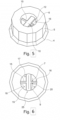
- the Fig.5 shows a further embodiment of a duckbill valve 6 in a perspective sectional view along a Fig.2 shown section line IV-IV through a nozzle 5 of a jet former 4.
- the further embodiment of the duckbill valve 6 differs from the first embodiment in that the thickening 12 comprises a first web 15 and a second web 16, which extend on both sides of the valve outlet 10 and orthogonal to the slot-shaped valve outlet 10.
- the Fig.6 shows the further design variant of the duckbill valve 6 from the same perspective as in the Fig.4 shown first embodiment of the duckbill valve 6.
- the first web 15 and the second web 16 extend perpendicular to the drawing plane from the beak tip 25 to the valve base 9 and parallel to the drawing plane from the outer surface 17 of the valve casing 7 to the inner wall 18 of the liquid channel 19. Furthermore, the first web 15 and the second web 16 have a web width 20, which here is (approximately) 0.2 mm.
- the present invention makes it possible to reduce or completely prevent dripping of liquid from a sanitary shower head.
Landscapes
- Bathtubs, Showers, And Their Attachments (AREA)
- Nozzles (AREA)
Description
- Die vorliegende Erfindung betrifft eine Sanitärbrause. Derartige Sanitärbrausen sind für Duschen oder Badewannen verwendbar, die insbesondere der Körperhygiene von Personen dienen.
- Duschen oder Badewannen weisen regelmäßig eine Kopfbrause, die beim Duschen einen Sprühstrahl von oben auf einen Benutzer der Dusche richtet, und/oder eine Handbrause auf, die beim Duschen durch den Benutzer von Hand führbar ist. Weiterhin sind Sanitärbrausen für Duschen oder Badewannen bekannt, mit denen eine Flüssigkeit mit unterschiedlichen Strahlarten, beispielsweise in Form von Regenstrahlen, Vollstrahlen, Massagestrahlen oder Perlstrahlen, abgebbar sind. Die Umstellung zwischen den einzelnen Strahlarten kann beispielsweise über manuell und/oder elektrisch betätigbare Umstellelemente, beispielsweise nach Art von Ventilen oder Magnetventilen, an den Sanitärbrausen erfolgen. Über die Umstellelemente ist die Flüssigkeit gezielt zu entsprechenden Strahlbildnern zur Ausbildung der gewünschten Strahlarten leitbar. Zur Steuerung bzw. Umstellung einer gewünschten Strahlart können Bedienelemente vorgesehen sein, mit denen ein Benutzer der Sanitärbrause die gewünschte Strahlart einstellen kann. Beim Abstellen einer Flüssigkeitsabgabe durch die Sanitärbrause kann es zu einem unerwünschten Nachtropfen der Flüssigkeit aus der Sanitärbrause kommen. Zum Verhindern dieses Nachtropfens sind Sanitärbrausen mit Auslassdüsen in Form von sogenannten Entenschnabelventilen bekannt. Ein Entenschnabelventil ist ein Ventil, das einen Ventilmantel in Form eines Entenschnabels aufweist. Solche Ventile sind auch als "Duckbill-Ventile" bekannt. Der Ventilmantel besteht zumindest teilweise aus Gummi oder einem synthetischen Elastomer, wie zum Beispiel Silikon, und umfasst eine Ventilbasis, über die die Flüssigkeit in das Entenschnabelventil einfließen kann. Der Ventilmantel verjüngt sich in einer Strömungsrichtung der Flüssigkeit bis zu einem schlitzförmigen Ventilauslass. Der schlitzförmige Ventilauslass ist geschlossen, wenn die Sanitärbrause nicht verwendet wird. Wird ein Zufluss der Flüssigkeit aktiviert, beispielsweise indem ein entsprechendes Zuflussventil in einer Zuflussleitung der Sanitärbrause geöffnet wird, öffnet sich der schlitzförmige Ventilauslass durch eine elastische Verformung des Ventilmantels infolge des PFlüssigkeitsdrucks, sodass die Flüssigkeit das Entenschnabelventil passieren kann. Nach dem Schließen des Zuflussventils der Sanitärbrause schließt sich der schlitzförmige Ventilauslass infolge des sinkenden Flüssigkeitsdrucks automatisch, sodass ein Nachtropfen der Flüssigkeit verhindert wird. Nachteilig an den Entenschnabelventilen ist, dass diese nach längerer Verwendung der Sanitärbrause verkalken können und dann nicht mehr vollständig schließen. Zudem schließen sich besonders dünnwandige Entenschnabelventile bereits nach wenigen Verwendungen nicht mehr vollständig. Hierdurch ist ein Nachtropfen der Sanitärbrause trotz Ausbildung von Entenschnabelventilen möglich. Siehe hierzu das Dokument
US4341239 . - Aufgabe der Erfindung ist es daher, die mit Bezug auf den Stand der Technik geschilderten Probleme zumindest teilweise zu lösen und insbesondere eine Sanitärbrause anzugeben, bei der ein Nachtropfen von Flüssigkeit reduziert oder vollständig verhindert ist.
- Diese Aufgaben werden gelöst mit einer Sanitärbrause gemäß den Merkmalen des unabhängigen Patentanspruchs. Weitere vorteilhafte Ausgestaltungen der Erfindung sind in den abhängigen Patentansprüchen angegeben. Es ist darauf hinzuweisen, dass die in den abhängigen Patentansprüchen einzeln aufgeführten Merkmale in beliebiger technologisch sinnvoller Weise miteinander kombiniert werden können und weitere Ausgestaltungen der Erfindung definieren. Darüber hinaus werden die in den Patentansprüchen angegebenen Merkmale in der Beschreibung näher präzisiert und erläutert, wobei weitere bevorzugte Ausgestaltungen der Erfindung dargestellt werden.
- Hierzu trägt eine Sanitärbrause bei, die zumindest die folgenden Komponenten aufweist:
- ein Gehäuse,
- zumindest einen Flüssigkeitszulauf für eine Flüssigkeit und
- zumindest einen Strahlbildner mit zumindest einem Flüssigkeitskanal, wobei der zumindest eine Flüssigkeitskanal mindestens ein Entenschnabelventil mit einem elastischen Ventilmantel aufweist, der sich in einer Strömungsrichtung der Flüssigkeit von einer Ventilbasis bis zu einem schlitzförmigen Ventilauslass erstreckt und wobei der Ventilmantel zumindest im Bereich des schlitzförmigen Ventilauslasses eine nach außen gerichtete Aufdickung aufweist.
- Die Sanitärbrause ist insbesondere für eine Dusche oder Badewanne verwendbar. Derartige Duschen oder Badewannen sind durch einen Benutzer insbesondere zum Zwecke der Körperpflege oder zur therapeutischen Anwendung verwendbar. Hierzu ist die Dusche oder Badewanne regelmäßig in einer Sanitäreinrichtung, wie zum Beispiel einem Badezimmer, angeordnet. Weiterhin kann die Dusche oder Badewanne auch in Anlagen mit Badeeinrichtung, wie z. B. Saunen, Whirlpools, Schwimmbädern usw., verwendet werden. Bei der Sanitärbrause handelt es sich beispielsweise um eine Kopfbrause oder Handbrause. Die Sanitärbrause dient der Abgabe einer Flüssigkeit, insbesondere Wasser. Hierzu weist die Sanitärbrause ein Gehäuse auf, das beispielsweise zumindest teilweise aus Kunststoff und/oder Metall, beispielsweise Edelstahl oder Messing, bestehen kann. Der Sanitärbrause ist die Flüssigkeit über zumindest einen Flüssigkeitszulauf zuführbar. Hierzu ist die Sanitärbrause über den zumindest einen Flüssigkeitszulauf an zumindest eine starre oder flexible Zuflussleitung oder ein Zuflussrohr anschließbar. Hierzu kann der zumindest eine Flüssigkeitszulauf beispielsweise mit einem Gewinde oder einem Bajonettverschluss ausgebildet sein. Die Flüssigkeit ist durch die Sanitärbrause in zumindest einer Strahlart abgebbar. Insbesondere ist die Flüssigkeit durch die Sanitärbrause in einer Mehrzahl von Strahlarten, beispielsweise in zwei bis vier Strahlarten, abgebbar. Bei den Strahlarten kann es sich beispielsweise um Regenstrahlen, Vollstrahlen, Massagestrahlen und/oder Perlstrahlen handeln. Insbesondere ist die Flüssigkeit bei der Benutzung der Sanitärbrause nur in einer oder zwei unterschiedlichen Strahlarten gleichzeitig abgebbar. Zum Wechseln der Strahlart kann die Sanitärbrause in zumindest einem Flüssigkeitskanal zumindest ein Ventil aufweisen, mittels dem die Flüssigkeit zu zumindest einem Strahlbildner für die jeweilige Strahlart leitbar ist. Der zumindest eine Flüssigkeitskanal verläuft insbesondere durch das Gehäuse und verbindet den zumindest einen Flüssigkeitszulauf mit dem zumindest einen Strahlbildner. Weiterhin kann sich der Flüssigkeitskanal beispielsweise auch durch den Strahlbildner und/oder durch eine Düse des Strahlbildners bis zu einer Auslassöffnung der Sanitärbrause erstrecken. Die Sanitärbrause kann je Strahlart einen Strahlbildner aufweisen. Der Strahlbildner weist zumindest eine Düse und/oder zumindest eine Auslassöffnung für die Flüssigkeit auf, durch die zumindest ein für die jeweilige Strahlart spezifischer Sprühstrahl der Flüssigkeit bildbar ist. Alternativ kann die Sanitärbrause einen (einzigen) Strahlbildner aufweisen, der für jede Strahlart zumindest eine Düse und/oder zumindest eine Auslassöffnung aufweist, wobei sich die zumindest eine Düse und/oder die zumindest eine Auslassöffnung für die unterschiedlichen Strahlarten, beispielsweise hinsichtlich ihrer Geometrie, unterscheiden. In diesem Fall ist die Flüssigkeit durch das zumindest eine Ventil (gezielt) zu der zumindest einen Düse und/oder der zumindest einen Auslassöffnung für die gewünschte Strahlart leitbar. Bei dem zumindest einen Ventil handelt es sich insbesondere um ein manuell oder elektrisch betätigbares Ventil, beispielsweise nach Art eines Magnetventils.
- Der zumindest eine Flüssigkeitskanal weist mindestens ein Entenschnabelventil mit einem elastischen Ventilmantel auf. Insbesondere ist jeder Auslassöffnung der Sanitärbrause zumindest ein Entenschnabelventil zugeordnet, sodass jede Auslassöffnung durch zumindest ein Entenschnabelventil verschließbar ist. Die Auslassöffnungen und/oder Düsen sind insbesondere jedoch nicht aus dem mindestens einen Entenschnabelventil gebildet. Das mindestens eine Entenschnabelventil befindet sich stattdessen bevorzugt in der Sanitärbrause, in dem zumindest einen Strahlbildner und/oder in der zumindest einen Düse der Sanitärbrause. Weiterhin kann in jeder Düse der Sanitärbrause zumindest ein Entenschnabelventil angeordnet sein. Der elastische Ventilmantel besteht zumindest teilweise aus Gummi oder einem synthetischen Elastomer, wie zum Beispiel Silikon. Weiterhin erstreckt sich der Ventilmantel in einer Strömungsrichtung der Flüssigkeit von einer Ventilbasis bis zu einem schlitzförmigen Ventilauslass. Der schlitzförmige Ventilauslass erstreckt sich orthogonal zu der Strömungsrichtung insbesondere gerade und/oder insbesondere nicht kreuzförmig. Das mindestens eine Entenschnabelventil kann in der Strömungsrichtung von der Ventilbasis bis zu dem Ventilauslass bzw. von der Ventilbasis bis zu einer Schnabelspitze eine Ventillänge von beispielsweise 1 mm (Millimeter) bis 5 mm, bevorzugt (im Wesentlichen) 2 mm aufweisen. Die Ventilbasis weist insbesondere einen Innendurchmesser von 1 mm bis 3 mm, bevorzugt 1,5 bis 1,6 mm auf. Weiterhin kann die Ventilbasis rohrförmig oder schlauchförmig ausgebildet sein. In erfindungsgemäßer Weise verjüngt sich ein Strömungsquerschnitt innerhalb des elastischen Ventilmantels ausgehend von der Ventilbasis in der Strömungsrichtung immer weiter zu dem schlitzförmigen Ventilauslass. Somit kann der Ventilmantel in der Strömungsrichtung innen trichterförmig ausgebildet sein. Das zumindest eine Entenschnabelventil ist insbesondere über seine Ventilbasis an einer Innenwand des zumindest einen Flüssigkeitskanals befestigt. Weiterhin kann das mindestens eine Entenschnabelventil einstückig mit dem zumindest einen Flüssigkeitskanal oder dem zumindest einen Strahlbildner ausgebildet sein, beispielsweise nach Art eines Spritzgussteils. Der schlitzförmige Ventilauslass befindet sich an der Schnabelspitze des Entenschnabelventils und ist geschlossen, wenn der Sanitärbrause keine Flüssigkeit zuströmt. Wird die Sanitärbrause verwendet, öffnet der sich in dem zumindest einen Flüssigkeitskanal aufbauende Flüssigkeitsdruck den schlitzförmigen Ventilauslass durch eine elastische Verformung des Ventilmantels. Wird die Verwendung der Sanitärbrause beendet, sodass der Sanitärbrause und/oder dem zumindest einen Flüssigkeitskanal keine Flüssigkeit mehr zufließt, schließt sich der schlitzförmige Ventilauslass aufgrund des sich abbauenden Flüssigkeitsdrucks automatisch. Der Ventilmantel weist zumindest im Bereich des schlitzförmigen Ventilauslasses eine nach außen gerichtete Aufdickung auf. Nach außen gerichtet bedeutet in diesem Zusammenhang insbesondere, dass die Aufdickung an einer Außenfläche des elastischen Ventilmantels ausgebildet ist. Die Aufdickung unterstützt das automatische Schließen des schlitzförmigen Ventilauslasses, indem es die Rückstellkraft des elastischen Ventilmantels (nur und/oder zumindest) im Bereich des schlitzförmigen Ventilauslasses verstärkt. Hierdurch kann verhindert werden, dass das mindestens eine Entenschnabelventil bei einer Verkalkung und/oder wegen einer zu geringen Wandstärke nicht ordnungsgemäß schließt und die Flüssigkeit aus der Sanitärbrause dadurch nachtropft. Die Aufdickung erstreckt sich jedoch bevorzugt nicht über die gesamte Außenfläche des elastischen Ventilmantels. Dies verhindert, dass sich das mindestens eine Flüssigkeitsventil bei geringen Flüssigkeitsdrücken nicht bzw. nicht ausreichend öffnet oder sich bei einer Mehrzahl von Flüssigkeitsventilen bei geringen Flüssigkeitsdrücken nur einzelne Entenschnabelventile öffnen, sodass die Sanitärbrause die Flüssigkeit mit einem ungleichmäßigen Strahlbild abgibt. Die Aufdickung kann sich in der Strömungsrichtung beispielsweise mit einer Aufdickungslänge von 0,2 mm bis 1 mm, bevorzugt 0,4 mm bis 0,5 mm erstrecken. Weiterhin kann die Aufdickung gerade ausgebildet sein. Dies bedeutet insbesondere, dass die Aufdickung parallel zu dem schlitzförmigen Ventilauslass zumindest teilweise eine konstante Wandstärke aufweist. Die Schnabelspitze kann in diesem Fall (im Wesentlichen) zudem rechteckförmig ausgebildet sein und/oder eine Schnabeldicke von 0,5 mm bis 2 mm, bevorzugt (circa) 0,8 mm aufweisen. Durch eine derartige Aufdickung wird das Schließen des schlitzförmigen Ventilauslasses unterstützt, ohne das Öffnungsverhalten des schlitzförmigen Ventilauslasses zu ändern.
- Der Ventilmantel kann außerhalb der Aufdickung eine erste Wandstärke und im Bereich der Aufdickung eine zweite Wandstärke aufweisen, die mindestens 10 % größer als die erste Wandstärke ist. Die erste Wandstärke und/oder die zweite Wandstärke können sich insbesondere orthogonal zu einer Innenfläche des Ventilmantels bemessen. Weiterhin kann die erste Wandstärke 0,1 mm bis 0,5 mm, bevorzugt (circa) 0,2 mm betragen.
- Die Aufdickung kann zumindest teilweise konvex ausgebildet sein. Insbesondere ist die Aufdickung entgegen der Strömungsrichtung betrachtet zumindest teilweise konvex ausgebildet. Dies kann bedeuten, dass die zweite Wandstärke in der Mitte des schlitzförmigen Ventilauslasses am größten ist und sich parallel zu dem schlitzförmigen Ventilauslass nach außen reduziert. Durch eine derartige Aufdickung wird das Schließen des schlitzförmigen Ventilauslasses unterstützt, wobei zum Öffnen der Mitte des schlitzförmigen Ventilauslasses ein höherer Flüssigkeitsdruck benötigt wird als außerhalb der Mitte des schlitzförmigen Ventilauslasses.
- Die Aufdickung kann zumindest teilweise konkav ausgebildet sein. Insbesondere ist die Aufdickung entgegen der Strömungsrichtung betrachtet zumindest teilweise konkav ausgebildet. Dies kann bedeuten, dass die zweite Wandstärke in der Mitte des schlitzförmigen Ventilauslasses am kleinsten ist und sich parallel zu dem schlitzförmigen Ventilauslass nach außen vergrößert. Durch eine derartige Aufdickung wird das Schließen des schlitzförmigen Ventilauslasses unterstützt, wobei bei der Öffnung des schlitzförmigen Ventilauslasses sich der mittlere Bereich des schlitzförmigen Ventilauslasses schneller öffnet, weil im mittleren Bereich des schlitzförmigen Ventilauslasses weniger Material verdrängt bzw. elastisch verformt werden muss.
- In erfindungsgemäßer Weise ist die Aufdickung zumindest teilweise nach Art zumindest eines Stegs ausgebildet. Der zumindest eine Steg ist insbesondere wandförmig ausgebildet. Der zumindest eine Steg ist beim Öffnen des schlitzförmigen Ventilauslasses insbesondere elastisch verformbar. Hierdurch kann der zumindest eine Steg, insbesondere durch seine Rückstellkraft, das Schließen des schlitzförmigen Ventilauslasses unterstützen. Das mindestens eine Entenschnabelventil weist insbesondere einen ersten Steg und einen zweiten Steg auf. Der erste Steg und der zweite Steg befinden sich in Bezug zum schlitzförmigen Ventilauslass insbesondere auf gegenüberliegenden Seiten des Ventilmantels. Weiterhin fluchten der erste Steg und der zweite Steg insbesondere miteinander.
- Der zumindest eine Steg kann sich von der Ventilbasis bis zu dem schlitzförmigen Ventilauslass erstrecken. Insbesondere kann sich der zumindest eine Steg von der Ventilbasis bis zu der Schnabelspitze des mindestens einen Entenschnabelventils erstrecken.
- Der zumindest eine Steg kann sich von einer Außenfläche des Ventilmantels bis zu einer Innenwand des zumindest einen Flüssigkeitskanals erstrecken.
- Der zumindest eine Steg kann eine Stegbreite von 0,1 mm bis 0,5 mm aufweisen bevorzugt weist der zumindest eine Steg eine Stegbreite von (im Wesentlichen) 0,2 mm auf.
- In erfindungsgemäßer Weise verläuft der zumindest eine Steg orthogonal zu dem schlitzförmigen Ventilauslass.
- Die Aufdickung kann beim Öffnen des schlitzförmigen Ventilauslasses zumindest teilweise elastisch verformbar sein. Durch die elastische Verformung der Aufdickung kann in der Aufdickung Energie zum Schließen des schlitzförmigen Ventilauslasses speicherbar sein.
- Die Erfindung sowie das technische Umfeld werden nachfolgend anhand der Figuren näher erläutert. Es ist darauf hinzuweisen, dass die Figuren eine besonders bevorzugte Ausführungsvariante der Erfindung zeigen, diese jedoch nicht darauf beschränkt ist. Dabei sind gleiche Bauteile in den Figuren mit denselben Bezugszeichen versehen. Es zeigen beispielhaft und schematisch:
- Fig. 1:
- eine Sanitärbrause;
- Fig. 2:
- eine erste Ausführungsvariante eines Entenschnabelventils der Sanitärbrause in einer ersten Schnittdarstellung;
- Fig. 3:
- die erste Ausführungsvariante des Entenschnabelventils in einer vergrößerten Detailansicht.
- Fig. 4:
- die erste Ausführungsvariante des Entenschnabelventils in einer zweiten Schnittdarstellung;
- Fig. 5:
- eine weitere Ausführungsvariante des Entenschnabelventils der Sanitärbrause in einer perspektivischen Schnittdarstellung; und
- Fig. 6:
- die weitere Ausführungsvariante des Entenschnabelventils der Sanitärbrause in einer weiteren Schnittdarstellung.
- Die
Fig. 1 zeigt eine Sanitärbrause 1 aus seitlicher Perspektive. Die Sanitärbrause 1 ist hier nach Art einer Handbrause ausgebildet und weist ein Gehäuse 2 mit einem Flüssigkeitszulauf 3 auf. Mittels des Flüssigkeitszulaufs 3 ist die Sanitärbrause 1 mit einem hier nicht gezeigten Zulaufschlauch verbindbar. Durch den Zulaufschlauch ist der Sanitärarmatur 1 eine Flüssigkeit zuführbar, die über den Flüssigkeitszulauf 3 in das Gehäuse 2 der Sanitärbrause 1 eintritt. Innerhalb des Gehäuses 2 ist die Flüssigkeit über hier nicht gezeigte Kanäle und/oder Ventile einem Strahlbildner 4 der Sanitärbrause 1 zuführbar. Der Strahlbildner 4 weist eine Vielzahl von Düsen 5 auf, über die bei einer Verwendung der Sanitärbrause 1 die Flüssigkeit in einer gewünschten Strahlart, beispielsweise als Regenstrahlen, an eine Umgebung 21 abgebbar ist. - Die
Fig. 2 zeigt eine erste Ausführungsvariante eines Entenschnabelventils einer Düse 5 des Strahlbildners 4 in einer Schnittdarstellung entlang der in derFig. 1 gezeigten Schnittlinie II-II. Die Düse 5 erstreckt sich von einer runden Strahlbildnermatte 22 vertikal nach unten. Weiterhin weist die Düse 5 einen Flüssigkeitskanal 19 auf, der sich durch die Strahlbildnermatte 22 bis zu einer Auslassöffnung 23 erstreckt. Die über den in derFig. 1 gezeigten Flüssigkeitszulauf 3 in das Gehäuse 2 der Sanitärbrause 1 eintretende Flüssigkeit strömt bei einer Verwendung der Sanitärbrause 1 in einer Strömungsrichtung 8 durch den Flüssigkeitskanal 19 und tritt über die Auslassöffnung 23 aus der Düse 5 in die Umgebung 21 aus. In dem Flüssigkeitskanal 19 ist das Entenschnabelventil 6 angeordnet, das der Auslassöffnung 23 in der Strömungsrichtung 8 vorgelagert ist. Das Entenschnabelventil 6 weist einen elastischen Ventilmantel 7 auf, der sich in der Strömungsrichtung 8 von einer Ventilbasis 9 bis zu einem schlitzförmigen Ventilauslass 10 erstreckt. Der Ventilmantel 7 ist an der Ventilbasis 9 an einer Innenwand 18 des Flüssigkeitskanals 19 befestigt und weist einen Ventilbasisdurchmesser 26 auf, der hier (circa) 1,6 mm beträgt. Der Ventilbasisdurchmesser 26 entspricht im Bereich der Ventilbasis 9 einem Kanaldurchmesser 27 des Flüssigkeitskanals 19. Der Ventilmantel 7 weist daher im Bereich der Ventilbasis 9 einen kreisförmigen Innendurchmesser 24 auf. Ausgehend von der Ventilbasis 9 verjüngt sich der Ventilmantel 7 bzw. der Innendurchmesser 24 des Ventilmantels 7 in der Strömungsrichtung 8 trichterförmig bis zu dem schlitzförmigen Ventilauslass 10 an einer Schnabelspitze 25 des Entenschnabelventils 6 mit einem Verjüngungswinkel 32, der hier (circa) 45° beträgt. Der Innendurchmesser 24 des Ventilmantels 7 ändert sich daher ausgehend von der Ventilbasis 9 bis zu dem schlitzförmigen Ventilauslass 10 von einer kreisförmigen Form immer weiter zu einer ovalen, (im Wesentlichen) rechteckigen oder linienförmigen Form. Das Entenschnabelventil 6 weist von der Ventilbasis 9 bis zu der Schnabelspitze 25 eine Ventillänge 11 auf, die hier (circa) 2 mm beträgt. Bei der Verwendung der Sanitärarmatur 1 verformt die durch den Flüssigkeitskanal 19 in der Strömungsrichtung 8 in das Entenschnabelventil 6 strömende Flüssigkeit infolge des Flüssigkeitsdrucks den Ventilmantel 7 elastisch, sodass der schlitzförmigen Ventilauslass 10 gespreizt wird und sich damit öffnet. Nach der Verwendung der Sanitärarmatur 1 schließt sich der schlitzförmigen Ventilauslass 10 automatisch, sodass ein Nachtropfen der Flüssigkeit aus der Auslassöffnung 23 verhinderbar ist. - Die
Fig. 3 zeigt die Schnabelspitze 25 der ersten Ausführungsvariante des Entenschnabelventils 6 in dem in derFig. 2 gezeigten Bereich III. Der Ventilmantel 7 weist im Bereich des schlitzförmigen Ventilauslasses 10, d. h. im Bereich der Schnabelspitze 25 eine nach außen gerichtete Aufdickung 12 auf. Außerhalb der Aufdickung 12 weist der Ventilmantel 7 eine erste Wandstärke 13 und im Bereich der Aufdickung 12 eine zweite Wandstärke 14 auf, die größer als die erste Wandstärke 13 ist. Die erste Wandstärke 13 beträgt (circa) 0,2 mm. Die erste Wandstärke 13 und die zweite Wandstärke 14 bemessen sich senkrecht zu einer Innenfläche 29 des Ventilmantels 7. Ausgehend von einer Außenfläche 17 des Ventilmantels 7 erhebt sich die Aufdickung 12 mit einer Erhebungshöhe 28. Die Aufdickung 12 weist zudem in der Strömungsrichtung 8 eine Aufdickungslänge 30 auf, die hier (circa) 0,45 mm beträgt. Weiterhin führt die Aufdickung 12 (senkrecht zur Strömungsrichtung 8 und/oder senkrecht zum schlitzförmigen Ventilauslass 10) zu einer Schnabeldicke 31 der Schnabelspitze 25 des Entenschnabelventils 6, die hier (circa) 0,8 mm beträgt. - Die
Fig. 4 zeigt die Düse 5 des Strahlbildners 4 entlang der in derFig. 2 gezeigten Schnittlinie IV-IV. Es handelt sich hierbei insbesondere um eine Draufsicht auf den Ventilmantel 7 des Entenschnabelventils 6 in dem Flüssigkeitskanal 19. Zu erkennen ist hier insbesondere die Schnabelspitze 25 des Entenschnabelventils 6 mit der Aufdickung 12 sowie dem schlitzförmigen Ventilauslass 10. Der schlitzförmige Ventilauslass 10 weist eine Auslassbreite 33 auf, die hier (circa) 1,3 mm beträgt. Die Aufdickung 12 ist bei der ersten Ausführungsvariante des Entenschnabelventils 6 gerade ausgebildet. Dies bedeutet, dass die Aufdickung 12 parallel zu dem schlitzförmigen Ventilauslass 10 zu einer konstanten Schnabeldicke 31 führt. - Die
Fig. 5 zeigt eine weitere Ausführungsvariante eines Entenschnabelventils 6 in einer perspektivischen Schnittdarstellung entlang einer in derFig. 2 gezeigten Schnittlinie IV-IV durch eine Düse 5 eines Strahlbildners 4. Die weitere Ausführungsvariante des Entenschnabelventils 6 unterscheidet sich von der ersten Ausführungsvariante dadurch, dass die Aufdickung 12 einem ersten Steg 15 und einen zweiten Steg 16 umfasst, die sich beidseitig von dem Ventilauslass 10 und orthogonal zu dem schlitzförmigen Ventilauslass 10 erstrecken. - Die
Fig. 6 zeigt die weitere Ausführungsvariante des Entenschnabelventils 6 aus gleicher Perspektive wie die in derFig. 4 gezeigte erste Ausführungsvariante des Entenschnabelventils 6. Der erste Steg 15 und der zweite Steg 16 erstrecken sich senkrecht zur Zeichnungsebene von der Schnabelspitze 25 bis zur Ventilbasis 9 sowie parallel zur Zeichnungsebene von der Außenfläche 17 des Ventilmantels 7 bis zur Innenwand 18 des Flüssigkeitskanals 19. Weiterhin weisen der erste Steg 15 und der zweite Steg 16 eine Stegbreite 20 auf, die hier (circa) 0,2 mm beträgt. - Durch die vorliegende Erfindung ist ein Nachtropfen einer Flüssigkeit aus einer Sanitärbrause reduzierbar oder vollständig verhinderbar.
-
- 1
- Sanitärbrause
- 2
- Gehäuse
- 3
- Flüssigkeitszulauf
- 4
- Strahlbildner
- 5
- Düse
- 6
- Entenschnabelventil
- 7
- Ventilmantel
- 8
- Strömungsrichtung
- 9
- Ventilbasis
- 10
- Ventilauslass
- 11
- Ventillänge
- 12
- Aufdickung
- 13
- erste Wandstärke
- 14
- zweite Wandstärke
- 15
- erster Steg
- 16
- zweiter Steg
- 17
- Außenfläche
- 18
- Innenwand
- 19
- Flüssigkeitskanal
- 20
- Stegbreite
- 21
- Umgebung
- 22
- Strahlbildnermatte
- 23
- Auslassöffnung
- 24
- Innendurchmesser
- 25
- Schnabelspitze
- 26
- Ventilbasisdurchmesser
- 27
- Kanaldurchmesser
- 28
- Erhebungshöhe
- 29
- Innenfläche
- 30
- Aufdickungslänge
- 31
- Schnabeldicke
- 32
- Verjüngungswinkel
- 33
- Auslassbreite
Claims (8)
- Sanitärbrause (1), zumindest aufweisend:- ein Gehäuse (2),- zumindest einen Flüssigkeitszulauf (3) für eine Flüssigkeit und- zumindest einen Strahlbildner (4) mit zumindest einem Flüssigkeitskanal (19), wobei der zumindest eine Flüssigkeitskanal (19) mindestens ein Entenschnabelventil (6) mit einem elastischen Ventilmantel (7) aufweist, der sich in einer Strömungsrichtung (8) der Flüssigkeit von einer Ventilbasis (9) bis zu einem schlitzförmigen Ventilauslass (10) erstreckt und wobei der Ventilmantel (7) zumindest im Bereich des schlitzförmigen Ventilauslasses (10) eine nach außen gerichtete Aufdickung (12) aufweist, wobei die Aufdickung (12) zumindest teilweise nach Art zumindest eines Stegs (15, 16) ausgebildet ist, wobei der zumindest eine Steg (15, 16) orthogonal zu dem schlitzförmigen Ventilauslass (10) verläuft, wobei sich ein Strömungsquerschnitt innerhalb des elastischen Ventilmantels (7) ausgehend von der Ventilbasis (9) in der Strömungsrichtung (8) immer weiter zu dem schlitzförmigen Ventilauslass (10) verjüngt.
- Sanitärbrause (1) nach Patentanspruch 1, wobei der Ventilmantel (7) außerhalb der Aufdickung (12) eine erste Wandstärke (13) und im Bereich der Aufdickung (12) eine zweite Wandstärke (14) aufweist, die mindestens 10 % größer als die erste Wandstärke (13) ist.
- Sanitärbrause (1) nach einem der vorhergehenden Patentansprüche, wobei die Aufdickung (12) zumindest teilweise konvex ausgebildet ist.
- Sanitärbrause (1) nach einem der vorhergehenden Patentansprüche, wobei die Aufdickung (12) zumindest teilweise konkav ausgebildet ist.
- Sanitärbrause (1) nach einem der vorhergehenden Patentansprüche, wobei sich der zumindest eine Steg (15, 16) von der Ventilbasis (9) bis zu dem schlitzförmigen Ventilauslass (10) erstreckt.
- Sanitärbrause (1) nach einem der vorhergehenden Patentansprüche, wobei sich der zumindest eine Steg (15, 16) von einer Außenfläche (17) des Ventilmantels (7) bis zu einer Innenwand (18) des zumindest einen Flüssigkeitskanals (19) der Düse (5) erstreckt.
- Sanitärbrause (1) nach einem der vorhergehenden Patentansprüche, wobei der zumindest eine Steg (15, 16) eine Stegbreite (20) von 0,1 mm bis 0,5 mm aufweist.
- Sanitärbrause (1) nach einem der vorhergehenden Patentansprüche, wobei die Aufdickung (12) beim Öffnen des schlitzförmigen Ventilauslasses (10) zumindest teilweise elastisch verformbar ist.
Applications Claiming Priority (2)
| Application Number | Priority Date | Filing Date | Title |
|---|---|---|---|
| DE102019105974.7A DE102019105974A1 (de) | 2019-03-08 | 2019-03-08 | Sanitärbrause aufweisend einen Strahlbildner mit mindestens einem Entenschnabelventil |
| PCT/EP2020/055298 WO2020182492A1 (de) | 2019-03-08 | 2020-02-28 | Sanitärbrause aufweisend einen strahlbildner mit mindestens einem entenschnabelventil |
Publications (2)
| Publication Number | Publication Date |
|---|---|
| EP3934812A1 EP3934812A1 (de) | 2022-01-12 |
| EP3934812B1 true EP3934812B1 (de) | 2024-08-07 |
Family
ID=69810783
Family Applications (1)
| Application Number | Title | Priority Date | Filing Date |
|---|---|---|---|
| EP20711057.8A Active EP3934812B1 (de) | 2019-03-08 | 2020-02-28 | Sanitärbrause aufweisend einen strahlbildner mit mindestens einem entenschnabelventil |
Country Status (5)
| Country | Link |
|---|---|
| US (1) | US11998933B2 (de) |
| EP (1) | EP3934812B1 (de) |
| CN (1) | CN113874119A (de) |
| DE (1) | DE102019105974A1 (de) |
| WO (1) | WO2020182492A1 (de) |
Families Citing this family (1)
| Publication number | Priority date | Publication date | Assignee | Title |
|---|---|---|---|---|
| CN105792635A (zh) * | 2013-11-27 | 2016-07-20 | 恩普乐股份有限公司 | 发射器及滴灌用输送管 |
Citations (3)
| Publication number | Priority date | Publication date | Assignee | Title |
|---|---|---|---|---|
| US4341239A (en) * | 1980-07-14 | 1982-07-27 | Vernay Laboratories, Inc. | Combination check-overpressure relief valve |
| US4524805A (en) * | 1983-07-08 | 1985-06-25 | Hoffman Allan C | Normally closed duckbill valve and method of manufacture |
| WO2010107723A2 (en) * | 2009-03-20 | 2010-09-23 | Itt Manufacturing Enterprises, Inc. | High pressure duckbill valve and insert |
Family Cites Families (26)
| Publication number | Priority date | Publication date | Assignee | Title |
|---|---|---|---|---|
| US3504699A (en) * | 1967-03-20 | 1970-04-07 | Grimar Inc | Check valve |
| DE3107808A1 (de) * | 1981-02-28 | 1982-09-16 | Friedrich Grohe Armaturenfabrik Gmbh & Co, 5870 Hemer | Selbstreinigender brausekopf |
| US5228625A (en) * | 1990-02-22 | 1993-07-20 | Masco Gmbh | Sprinkler head |
| AT402164B (de) * | 1992-11-04 | 1997-02-25 | Ideal Standard | Brausekopf |
| JPH06262101A (ja) * | 1992-11-04 | 1994-09-20 | Friedrich Grohe Ag | シャワーヘッド |
| JP2003502594A (ja) * | 1999-06-15 | 2003-01-21 | アイピー.ワン ピーティーワイ.リミテッド | 逆止め弁 |
| US6227464B1 (en) * | 1999-08-23 | 2001-05-08 | Masco Corporation Of Indiana | In-line basket filter and anti-siphon valve assembly for spray spout and the like |
| US20050187524A1 (en) * | 2000-12-19 | 2005-08-25 | Willis Allan F. | Sealing valve assembly for medical products |
| GB0121377D0 (en) * | 2001-09-04 | 2001-10-24 | Aqualisa Products Ltd | Shower handset |
| ATE428505T1 (de) * | 2002-06-17 | 2009-05-15 | Ergon S R L | Austragsvorrichtung für einen brausekopf |
| US7934620B2 (en) * | 2004-01-09 | 2011-05-03 | The Last Straw, Llc | Leakage protection |
| ITMI20041756A1 (it) * | 2004-09-15 | 2004-12-15 | Ergon S R L | Dispositivo diffusore per doccia |
| KR20100040632A (ko) * | 2008-10-10 | 2010-04-20 | 세비앙 주식회사 | 샤워기 헤드용 잔수 배출방지 가스켓 |
| CN201909076U (zh) * | 2010-11-02 | 2011-07-27 | 尼亚加拉节能产品(厦门)有限公司 | 新型流量控制器 |
| CN102645014A (zh) * | 2012-05-29 | 2012-08-22 | 侯全舵 | 带气泵的热水器 |
| JP5406340B2 (ja) * | 2012-07-18 | 2014-02-05 | 株式会社 Mtg | シャワーヘッド及びカートリッジ |
| CN203124148U (zh) * | 2013-01-31 | 2013-08-14 | 伟特(厦门)淋浴设备有限公司 | 一种新型吸气淋浴设备 |
| CN105142609B (zh) * | 2013-03-11 | 2018-09-28 | 株式会社Mtg | 沐浴用化妆剂以及化妆剂盒 |
| CN203448203U (zh) * | 2013-07-30 | 2014-02-26 | 科勒(中国)投资有限公司 | 浴缸及其浴缸按摩喷头 |
| NL2015082B1 (en) * | 2015-07-03 | 2017-01-30 | Avesto Tech B V | Duckbill valve. |
| CN205398987U (zh) * | 2016-03-02 | 2016-07-27 | 无锡好力泵业有限公司 | 洗衣机洗涤剂泵用鸭嘴阀机构 |
| DE102016219551B4 (de) * | 2016-10-07 | 2022-01-05 | Hansgrohe Se | Brausestrahlerzeugungsvorrichtung |
| IL249680B (en) * | 2016-12-21 | 2018-05-31 | Zabari Lidor | Self-sealing and disinfecting shower head |
| CN106984451A (zh) * | 2017-05-10 | 2017-07-28 | 北京航科阶跃科技有限公司 | 花洒、洗浴装置及洗浴系统 |
| DE102018201183B3 (de) * | 2018-01-25 | 2019-01-31 | Hansgrohe Se | Brausestrahlerzeugungsvorrichtung mit Überdruckventil |
| CN108869812B (zh) * | 2018-07-06 | 2024-04-16 | 嘉兴志嘉智能电器有限公司 | 负压防止虹吸的真空破坏器 |
-
2019
- 2019-03-08 DE DE102019105974.7A patent/DE102019105974A1/de active Pending
-
2020
- 2020-02-28 US US17/437,134 patent/US11998933B2/en active Active
- 2020-02-28 WO PCT/EP2020/055298 patent/WO2020182492A1/de not_active Ceased
- 2020-02-28 EP EP20711057.8A patent/EP3934812B1/de active Active
- 2020-02-28 CN CN202080034164.XA patent/CN113874119A/zh active Pending
Patent Citations (3)
| Publication number | Priority date | Publication date | Assignee | Title |
|---|---|---|---|---|
| US4341239A (en) * | 1980-07-14 | 1982-07-27 | Vernay Laboratories, Inc. | Combination check-overpressure relief valve |
| US4524805A (en) * | 1983-07-08 | 1985-06-25 | Hoffman Allan C | Normally closed duckbill valve and method of manufacture |
| WO2010107723A2 (en) * | 2009-03-20 | 2010-09-23 | Itt Manufacturing Enterprises, Inc. | High pressure duckbill valve and insert |
Also Published As
| Publication number | Publication date |
|---|---|
| CN113874119A (zh) | 2021-12-31 |
| US11998933B2 (en) | 2024-06-04 |
| US20220168757A1 (en) | 2022-06-02 |
| EP3934812A1 (de) | 2022-01-12 |
| DE102019105974A1 (de) | 2020-09-10 |
| WO2020182492A1 (de) | 2020-09-17 |
Similar Documents
| Publication | Publication Date | Title |
|---|---|---|
| EP3323949B1 (de) | Sanitäres einbauteil | |
| EP3338898B1 (de) | Brausestrahlaustrittsvorrichtung und damit ausgerüstete brause | |
| EP1001095B1 (de) | Wasserstrahlbelüfter | |
| EP1470298B1 (de) | Strahlregler | |
| DE112012005017B4 (de) | Vorrichtung zum Steuern einer Fluid-Strömung in einem Notfall-Waschsystem, Vorrichtung zum Steuern einer Fluid-Strömung und Waschsystem zum Liefern einer Fluid-Strömung | |
| EP3935224B1 (de) | Sanitärarmatur mit einem zweiwegeventil | |
| WO2011092008A1 (de) | Strahlregler | |
| EP4111007A1 (de) | Strahlregler für eine sanitärarmatur mit mindestens drei flüssigkeitskanälen | |
| DE102016213491A1 (de) | Brausestrahlerzeugungsvorrichtung | |
| DE102018121773A1 (de) | Brausekopf für eine Sanitärarmatur mit einer Mehrzahl von Membranventilen | |
| DE10394030T5 (de) | Fluidsteuervorrichtung | |
| EP2597213B1 (de) | Sanitäres Einbauteil | |
| EP3934812B1 (de) | Sanitärbrause aufweisend einen strahlbildner mit mindestens einem entenschnabelventil | |
| WO2020182491A1 (de) | Sanitärbrause aufweisend einen strahlbildner mit mindestens einem entenschnabelventil | |
| DE3886876T2 (de) | Hydromassage-Armatur mit automatischer Schliessvorrichtung. | |
| EP1716296B1 (de) | Sanitäre auslaufvorrichtung | |
| EP3702541B1 (de) | Brause für eine sanitärarmatur mit einer rückstellfeder | |
| DE2729198C2 (de) | Vorrichtung zur Regelung der Luftzufuhr bei Luftsprudelmatten in Luftsprudelmassagebädern | |
| DE102007010133B3 (de) | Strahlformer | |
| DE102021106072A1 (de) | Brause für eine Sanitärarmatur mit ausrückbarem Kammelement | |
| EP3844351A1 (de) | Brause für eine sanitärarmatur mit einem betätigungselement für eine mehrzahl von membranventilen | |
| WO2025011834A1 (de) | Brausestrahlerzeugungsvorrichtung mit tropfschutz | |
| DE102023133009A1 (de) | Duschvorrichtung mit einer Sanitärbrause | |
| DE20215272U1 (de) | Strahlregler | |
| DE10253840A1 (de) | Duschanordnung |
Legal Events
| Date | Code | Title | Description |
|---|---|---|---|
| STAA | Information on the status of an ep patent application or granted ep patent |
Free format text: STATUS: UNKNOWN |
|
| STAA | Information on the status of an ep patent application or granted ep patent |
Free format text: STATUS: THE INTERNATIONAL PUBLICATION HAS BEEN MADE |
|
| PUAI | Public reference made under article 153(3) epc to a published international application that has entered the european phase |
Free format text: ORIGINAL CODE: 0009012 |
|
| STAA | Information on the status of an ep patent application or granted ep patent |
Free format text: STATUS: REQUEST FOR EXAMINATION WAS MADE |
|
| 17P | Request for examination filed |
Effective date: 20210906 |
|
| AK | Designated contracting states |
Kind code of ref document: A1 Designated state(s): AL AT BE BG CH CY CZ DE DK EE ES FI FR GB GR HR HU IE IS IT LI LT LU LV MC MK MT NL NO PL PT RO RS SE SI SK SM TR |
|
| DAV | Request for validation of the european patent (deleted) | ||
| DAX | Request for extension of the european patent (deleted) | ||
| STAA | Information on the status of an ep patent application or granted ep patent |
Free format text: STATUS: EXAMINATION IS IN PROGRESS |
|
| 17Q | First examination report despatched |
Effective date: 20221013 |
|
| GRAP | Despatch of communication of intention to grant a patent |
Free format text: ORIGINAL CODE: EPIDOSNIGR1 |
|
| STAA | Information on the status of an ep patent application or granted ep patent |
Free format text: STATUS: GRANT OF PATENT IS INTENDED |
|
| INTG | Intention to grant announced |
Effective date: 20240507 |
|
| GRAS | Grant fee paid |
Free format text: ORIGINAL CODE: EPIDOSNIGR3 |
|
| GRAA | (expected) grant |
Free format text: ORIGINAL CODE: 0009210 |
|
| STAA | Information on the status of an ep patent application or granted ep patent |
Free format text: STATUS: THE PATENT HAS BEEN GRANTED |
|
| AK | Designated contracting states |
Kind code of ref document: B1 Designated state(s): AL AT BE BG CH CY CZ DE DK EE ES FI FR GB GR HR HU IE IS IT LI LT LU LV MC MK MT NL NO PL PT RO RS SE SI SK SM TR |
|
| REG | Reference to a national code |
Ref country code: GB Ref legal event code: FG4D Free format text: NOT ENGLISH |
|
| REG | Reference to a national code |
Ref country code: CH Ref legal event code: EP |
|
| REG | Reference to a national code |
Ref country code: IE Ref legal event code: FG4D Free format text: LANGUAGE OF EP DOCUMENT: GERMAN |
|
| REG | Reference to a national code |
Ref country code: DE Ref legal event code: R096 Ref document number: 502020008797 Country of ref document: DE |
|
| P01 | Opt-out of the competence of the unified patent court (upc) registered |
Free format text: CASE NUMBER: APP_48804/2024 Effective date: 20240827 |
|
| REG | Reference to a national code |
Ref country code: LT Ref legal event code: MG9D |
|
| REG | Reference to a national code |
Ref country code: NL Ref legal event code: MP Effective date: 20240807 |
|
| PG25 | Lapsed in a contracting state [announced via postgrant information from national office to epo] |
Ref country code: NO Free format text: LAPSE BECAUSE OF FAILURE TO SUBMIT A TRANSLATION OF THE DESCRIPTION OR TO PAY THE FEE WITHIN THE PRESCRIBED TIME-LIMIT Effective date: 20241107 |
|
| PG25 | Lapsed in a contracting state [announced via postgrant information from national office to epo] |
Ref country code: NL Free format text: LAPSE BECAUSE OF FAILURE TO SUBMIT A TRANSLATION OF THE DESCRIPTION OR TO PAY THE FEE WITHIN THE PRESCRIBED TIME-LIMIT Effective date: 20240807 Ref country code: PT Free format text: LAPSE BECAUSE OF FAILURE TO SUBMIT A TRANSLATION OF THE DESCRIPTION OR TO PAY THE FEE WITHIN THE PRESCRIBED TIME-LIMIT Effective date: 20241209 Ref country code: FI Free format text: LAPSE BECAUSE OF FAILURE TO SUBMIT A TRANSLATION OF THE DESCRIPTION OR TO PAY THE FEE WITHIN THE PRESCRIBED TIME-LIMIT Effective date: 20240807 Ref country code: PL Free format text: LAPSE BECAUSE OF FAILURE TO SUBMIT A TRANSLATION OF THE DESCRIPTION OR TO PAY THE FEE WITHIN THE PRESCRIBED TIME-LIMIT Effective date: 20240807 Ref country code: GR Free format text: LAPSE BECAUSE OF FAILURE TO SUBMIT A TRANSLATION OF THE DESCRIPTION OR TO PAY THE FEE WITHIN THE PRESCRIBED TIME-LIMIT Effective date: 20241108 |
|
| PG25 | Lapsed in a contracting state [announced via postgrant information from national office to epo] |
Ref country code: BG Free format text: LAPSE BECAUSE OF FAILURE TO SUBMIT A TRANSLATION OF THE DESCRIPTION OR TO PAY THE FEE WITHIN THE PRESCRIBED TIME-LIMIT Effective date: 20240807 |
|
| PG25 | Lapsed in a contracting state [announced via postgrant information from national office to epo] |
Ref country code: LV Free format text: LAPSE BECAUSE OF FAILURE TO SUBMIT A TRANSLATION OF THE DESCRIPTION OR TO PAY THE FEE WITHIN THE PRESCRIBED TIME-LIMIT Effective date: 20240807 |
|
| PG25 | Lapsed in a contracting state [announced via postgrant information from national office to epo] |
Ref country code: IS Free format text: LAPSE BECAUSE OF FAILURE TO SUBMIT A TRANSLATION OF THE DESCRIPTION OR TO PAY THE FEE WITHIN THE PRESCRIBED TIME-LIMIT Effective date: 20241207 |
|
| PG25 | Lapsed in a contracting state [announced via postgrant information from national office to epo] |
Ref country code: HR Free format text: LAPSE BECAUSE OF FAILURE TO SUBMIT A TRANSLATION OF THE DESCRIPTION OR TO PAY THE FEE WITHIN THE PRESCRIBED TIME-LIMIT Effective date: 20240807 |
|
| PG25 | Lapsed in a contracting state [announced via postgrant information from national office to epo] |
Ref country code: RS Free format text: LAPSE BECAUSE OF FAILURE TO SUBMIT A TRANSLATION OF THE DESCRIPTION OR TO PAY THE FEE WITHIN THE PRESCRIBED TIME-LIMIT Effective date: 20241107 Ref country code: ES Free format text: LAPSE BECAUSE OF FAILURE TO SUBMIT A TRANSLATION OF THE DESCRIPTION OR TO PAY THE FEE WITHIN THE PRESCRIBED TIME-LIMIT Effective date: 20240807 |
|
| PG25 | Lapsed in a contracting state [announced via postgrant information from national office to epo] |
Ref country code: RS Free format text: LAPSE BECAUSE OF FAILURE TO SUBMIT A TRANSLATION OF THE DESCRIPTION OR TO PAY THE FEE WITHIN THE PRESCRIBED TIME-LIMIT Effective date: 20241107 Ref country code: PT Free format text: LAPSE BECAUSE OF FAILURE TO SUBMIT A TRANSLATION OF THE DESCRIPTION OR TO PAY THE FEE WITHIN THE PRESCRIBED TIME-LIMIT Effective date: 20241209 Ref country code: PL Free format text: LAPSE BECAUSE OF FAILURE TO SUBMIT A TRANSLATION OF THE DESCRIPTION OR TO PAY THE FEE WITHIN THE PRESCRIBED TIME-LIMIT Effective date: 20240807 Ref country code: NO Free format text: LAPSE BECAUSE OF FAILURE TO SUBMIT A TRANSLATION OF THE DESCRIPTION OR TO PAY THE FEE WITHIN THE PRESCRIBED TIME-LIMIT Effective date: 20241107 Ref country code: NL Free format text: LAPSE BECAUSE OF FAILURE TO SUBMIT A TRANSLATION OF THE DESCRIPTION OR TO PAY THE FEE WITHIN THE PRESCRIBED TIME-LIMIT Effective date: 20240807 Ref country code: LV Free format text: LAPSE BECAUSE OF FAILURE TO SUBMIT A TRANSLATION OF THE DESCRIPTION OR TO PAY THE FEE WITHIN THE PRESCRIBED TIME-LIMIT Effective date: 20240807 Ref country code: IS Free format text: LAPSE BECAUSE OF FAILURE TO SUBMIT A TRANSLATION OF THE DESCRIPTION OR TO PAY THE FEE WITHIN THE PRESCRIBED TIME-LIMIT Effective date: 20241207 Ref country code: HR Free format text: LAPSE BECAUSE OF FAILURE TO SUBMIT A TRANSLATION OF THE DESCRIPTION OR TO PAY THE FEE WITHIN THE PRESCRIBED TIME-LIMIT Effective date: 20240807 Ref country code: GR Free format text: LAPSE BECAUSE OF FAILURE TO SUBMIT A TRANSLATION OF THE DESCRIPTION OR TO PAY THE FEE WITHIN THE PRESCRIBED TIME-LIMIT Effective date: 20241108 Ref country code: FI Free format text: LAPSE BECAUSE OF FAILURE TO SUBMIT A TRANSLATION OF THE DESCRIPTION OR TO PAY THE FEE WITHIN THE PRESCRIBED TIME-LIMIT Effective date: 20240807 Ref country code: ES Free format text: LAPSE BECAUSE OF FAILURE TO SUBMIT A TRANSLATION OF THE DESCRIPTION OR TO PAY THE FEE WITHIN THE PRESCRIBED TIME-LIMIT Effective date: 20240807 Ref country code: BG Free format text: LAPSE BECAUSE OF FAILURE TO SUBMIT A TRANSLATION OF THE DESCRIPTION OR TO PAY THE FEE WITHIN THE PRESCRIBED TIME-LIMIT Effective date: 20240807 |
|
| PGFP | Annual fee paid to national office [announced via postgrant information from national office to epo] |
Ref country code: DE Payment date: 20250220 Year of fee payment: 6 |
|
| PG25 | Lapsed in a contracting state [announced via postgrant information from national office to epo] |
Ref country code: DK Free format text: LAPSE BECAUSE OF FAILURE TO SUBMIT A TRANSLATION OF THE DESCRIPTION OR TO PAY THE FEE WITHIN THE PRESCRIBED TIME-LIMIT Effective date: 20240807 Ref country code: SM Free format text: LAPSE BECAUSE OF FAILURE TO SUBMIT A TRANSLATION OF THE DESCRIPTION OR TO PAY THE FEE WITHIN THE PRESCRIBED TIME-LIMIT Effective date: 20240807 |
|
| PG25 | Lapsed in a contracting state [announced via postgrant information from national office to epo] |
Ref country code: EE Free format text: LAPSE BECAUSE OF FAILURE TO SUBMIT A TRANSLATION OF THE DESCRIPTION OR TO PAY THE FEE WITHIN THE PRESCRIBED TIME-LIMIT Effective date: 20240807 |
|
| PG25 | Lapsed in a contracting state [announced via postgrant information from national office to epo] |
Ref country code: CZ Free format text: LAPSE BECAUSE OF FAILURE TO SUBMIT A TRANSLATION OF THE DESCRIPTION OR TO PAY THE FEE WITHIN THE PRESCRIBED TIME-LIMIT Effective date: 20240807 |
|
| PG25 | Lapsed in a contracting state [announced via postgrant information from national office to epo] |
Ref country code: SK Free format text: LAPSE BECAUSE OF FAILURE TO SUBMIT A TRANSLATION OF THE DESCRIPTION OR TO PAY THE FEE WITHIN THE PRESCRIBED TIME-LIMIT Effective date: 20240807 |
|
| REG | Reference to a national code |
Ref country code: DE Ref legal event code: R097 Ref document number: 502020008797 Country of ref document: DE |
|
| PLBE | No opposition filed within time limit |
Free format text: ORIGINAL CODE: 0009261 |
|
| STAA | Information on the status of an ep patent application or granted ep patent |
Free format text: STATUS: NO OPPOSITION FILED WITHIN TIME LIMIT |
|
| 26N | No opposition filed |
Effective date: 20250508 |
|
| PG25 | Lapsed in a contracting state [announced via postgrant information from national office to epo] |
Ref country code: SE Free format text: LAPSE BECAUSE OF FAILURE TO SUBMIT A TRANSLATION OF THE DESCRIPTION OR TO PAY THE FEE WITHIN THE PRESCRIBED TIME-LIMIT Effective date: 20240807 |
|
| PG25 | Lapsed in a contracting state [announced via postgrant information from national office to epo] |
Ref country code: MC Free format text: LAPSE BECAUSE OF FAILURE TO SUBMIT A TRANSLATION OF THE DESCRIPTION OR TO PAY THE FEE WITHIN THE PRESCRIBED TIME-LIMIT Effective date: 20240807 |
|
| REG | Reference to a national code |
Ref country code: CH Ref legal event code: PL |
|
| PG25 | Lapsed in a contracting state [announced via postgrant information from national office to epo] |
Ref country code: LU Free format text: LAPSE BECAUSE OF NON-PAYMENT OF DUE FEES Effective date: 20250228 |
|
| PG25 | Lapsed in a contracting state [announced via postgrant information from national office to epo] |
Ref country code: CH Free format text: LAPSE BECAUSE OF NON-PAYMENT OF DUE FEES Effective date: 20250228 |
|
| GBPC | Gb: european patent ceased through non-payment of renewal fee |
Effective date: 20250228 |