EP3854591B1 - Lithographischer druckplattenvorläufer und lithographisches druckverfahren - Google Patents
Lithographischer druckplattenvorläufer und lithographisches druckverfahren Download PDFInfo
- Publication number
- EP3854591B1 EP3854591B1 EP21162555.3A EP21162555A EP3854591B1 EP 3854591 B1 EP3854591 B1 EP 3854591B1 EP 21162555 A EP21162555 A EP 21162555A EP 3854591 B1 EP3854591 B1 EP 3854591B1
- Authority
- EP
- European Patent Office
- Prior art keywords
- treatment
- resin
- image recording
- recording layer
- particles
- Prior art date
- Legal status (The legal status is an assumption and is not a legal conclusion. Google has not performed a legal analysis and makes no representation as to the accuracy of the status listed.)
- Active
Links
Images

Classifications
-
- B—PERFORMING OPERATIONS; TRANSPORTING
- B41—PRINTING; LINING MACHINES; TYPEWRITERS; STAMPS
- B41N—PRINTING PLATES OR FOILS; MATERIALS FOR SURFACES USED IN PRINTING MACHINES FOR PRINTING, INKING, DAMPING, OR THE LIKE; PREPARING SUCH SURFACES FOR USE AND CONSERVING THEM
- B41N1/00—Printing plates or foils; Materials therefor
- B41N1/12—Printing plates or foils; Materials therefor non-metallic other than stone, e.g. printing plates or foils comprising inorganic materials in an organic matrix
- B41N1/14—Lithographic printing foils
-
- B—PERFORMING OPERATIONS; TRANSPORTING
- B41—PRINTING; LINING MACHINES; TYPEWRITERS; STAMPS
- B41C—PROCESSES FOR THE MANUFACTURE OR REPRODUCTION OF PRINTING SURFACES
- B41C1/00—Forme preparation
- B41C1/10—Forme preparation for lithographic printing; Master sheets for transferring a lithographic image to the forme
- B41C1/1008—Forme preparation for lithographic printing; Master sheets for transferring a lithographic image to the forme by removal or destruction of lithographic material on the lithographic support, e.g. by laser or spark ablation; by the use of materials rendered soluble or insoluble by heat exposure, e.g. by heat produced from a light to heat transforming system; by on-the-press exposure or on-the-press development, e.g. by the fountain of photolithographic materials
- B41C1/1016—Forme preparation for lithographic printing; Master sheets for transferring a lithographic image to the forme by removal or destruction of lithographic material on the lithographic support, e.g. by laser or spark ablation; by the use of materials rendered soluble or insoluble by heat exposure, e.g. by heat produced from a light to heat transforming system; by on-the-press exposure or on-the-press development, e.g. by the fountain of photolithographic materials characterised by structural details, e.g. protective layers, backcoat layers or several imaging layers
-
- B—PERFORMING OPERATIONS; TRANSPORTING
- B41—PRINTING; LINING MACHINES; TYPEWRITERS; STAMPS
- B41N—PRINTING PLATES OR FOILS; MATERIALS FOR SURFACES USED IN PRINTING MACHINES FOR PRINTING, INKING, DAMPING, OR THE LIKE; PREPARING SUCH SURFACES FOR USE AND CONSERVING THEM
- B41N1/00—Printing plates or foils; Materials therefor
- B41N1/04—Printing plates or foils; Materials therefor metallic
- B41N1/08—Printing plates or foils; Materials therefor metallic for lithographic printing
-
- B—PERFORMING OPERATIONS; TRANSPORTING
- B41—PRINTING; LINING MACHINES; TYPEWRITERS; STAMPS
- B41N—PRINTING PLATES OR FOILS; MATERIALS FOR SURFACES USED IN PRINTING MACHINES FOR PRINTING, INKING, DAMPING, OR THE LIKE; PREPARING SUCH SURFACES FOR USE AND CONSERVING THEM
- B41N3/00—Preparing for use and conserving printing surfaces
-
- G—PHYSICS
- G03—PHOTOGRAPHY; CINEMATOGRAPHY; ANALOGOUS TECHNIQUES USING WAVES OTHER THAN OPTICAL WAVES; ELECTROGRAPHY; HOLOGRAPHY
- G03F—PHOTOMECHANICAL PRODUCTION OF TEXTURED OR PATTERNED SURFACES, e.g. FOR PRINTING, FOR PROCESSING OF SEMICONDUCTOR DEVICES; MATERIALS THEREFOR; ORIGINALS THEREFOR; APPARATUS SPECIALLY ADAPTED THEREFOR
- G03F7/00—Photomechanical, e.g. photolithographic, production of textured or patterned surfaces, e.g. printing surfaces; Materials therefor, e.g. comprising photoresists; Apparatus specially adapted therefor
- G03F7/004—Photosensitive materials
- G03F7/027—Non-macromolecular photopolymerisable compounds having carbon-to-carbon double bonds, e.g. ethylenic compounds
- G03F7/032—Non-macromolecular photopolymerisable compounds having carbon-to-carbon double bonds, e.g. ethylenic compounds with binders
- G03F7/033—Non-macromolecular photopolymerisable compounds having carbon-to-carbon double bonds, e.g. ethylenic compounds with binders the binders being polymers obtained by reactions only involving carbon-to-carbon unsaturated bonds, e.g. vinyl polymers
-
- G—PHYSICS
- G03—PHOTOGRAPHY; CINEMATOGRAPHY; ANALOGOUS TECHNIQUES USING WAVES OTHER THAN OPTICAL WAVES; ELECTROGRAPHY; HOLOGRAPHY
- G03F—PHOTOMECHANICAL PRODUCTION OF TEXTURED OR PATTERNED SURFACES, e.g. FOR PRINTING, FOR PROCESSING OF SEMICONDUCTOR DEVICES; MATERIALS THEREFOR; ORIGINALS THEREFOR; APPARATUS SPECIALLY ADAPTED THEREFOR
- G03F7/00—Photomechanical, e.g. photolithographic, production of textured or patterned surfaces, e.g. printing surfaces; Materials therefor, e.g. comprising photoresists; Apparatus specially adapted therefor
- G03F7/004—Photosensitive materials
- G03F7/09—Photosensitive materials characterised by structural details, e.g. supports, auxiliary layers
- G03F7/11—Photosensitive materials characterised by structural details, e.g. supports, auxiliary layers having cover layers or intermediate layers, e.g. subbing layers
-
- B—PERFORMING OPERATIONS; TRANSPORTING
- B41—PRINTING; LINING MACHINES; TYPEWRITERS; STAMPS
- B41C—PROCESSES FOR THE MANUFACTURE OR REPRODUCTION OF PRINTING SURFACES
- B41C2201/00—Location, type or constituents of the non-imaging layers in lithographic printing formes
- B41C2201/02—Cover layers; Protective layers
-
- B—PERFORMING OPERATIONS; TRANSPORTING
- B41—PRINTING; LINING MACHINES; TYPEWRITERS; STAMPS
- B41C—PROCESSES FOR THE MANUFACTURE OR REPRODUCTION OF PRINTING SURFACES
- B41C2201/00—Location, type or constituents of the non-imaging layers in lithographic printing formes
- B41C2201/06—Backcoats; Back layers
-
- B—PERFORMING OPERATIONS; TRANSPORTING
- B41—PRINTING; LINING MACHINES; TYPEWRITERS; STAMPS
- B41C—PROCESSES FOR THE MANUFACTURE OR REPRODUCTION OF PRINTING SURFACES
- B41C2201/00—Location, type or constituents of the non-imaging layers in lithographic printing formes
- B41C2201/10—Location, type or constituents of the non-imaging layers in lithographic printing formes characterised by inorganic compounds, e.g. pigments
-
- B—PERFORMING OPERATIONS; TRANSPORTING
- B41—PRINTING; LINING MACHINES; TYPEWRITERS; STAMPS
- B41C—PROCESSES FOR THE MANUFACTURE OR REPRODUCTION OF PRINTING SURFACES
- B41C2201/00—Location, type or constituents of the non-imaging layers in lithographic printing formes
- B41C2201/14—Location, type or constituents of the non-imaging layers in lithographic printing formes characterised by macromolecular organic compounds, e.g. binder, adhesives
-
- B—PERFORMING OPERATIONS; TRANSPORTING
- B41—PRINTING; LINING MACHINES; TYPEWRITERS; STAMPS
- B41C—PROCESSES FOR THE MANUFACTURE OR REPRODUCTION OF PRINTING SURFACES
- B41C2210/00—Preparation or type or constituents of the imaging layers, in relation to lithographic printing forme preparation
- B41C2210/04—Negative working, i.e. the non-exposed (non-imaged) areas are removed
-
- B—PERFORMING OPERATIONS; TRANSPORTING
- B41—PRINTING; LINING MACHINES; TYPEWRITERS; STAMPS
- B41C—PROCESSES FOR THE MANUFACTURE OR REPRODUCTION OF PRINTING SURFACES
- B41C2210/00—Preparation or type or constituents of the imaging layers, in relation to lithographic printing forme preparation
- B41C2210/06—Developable by an alkaline solution
-
- B—PERFORMING OPERATIONS; TRANSPORTING
- B41—PRINTING; LINING MACHINES; TYPEWRITERS; STAMPS
- B41C—PROCESSES FOR THE MANUFACTURE OR REPRODUCTION OF PRINTING SURFACES
- B41C2210/00—Preparation or type or constituents of the imaging layers, in relation to lithographic printing forme preparation
- B41C2210/08—Developable by water or the fountain solution
-
- B—PERFORMING OPERATIONS; TRANSPORTING
- B41—PRINTING; LINING MACHINES; TYPEWRITERS; STAMPS
- B41C—PROCESSES FOR THE MANUFACTURE OR REPRODUCTION OF PRINTING SURFACES
- B41C2210/00—Preparation or type or constituents of the imaging layers, in relation to lithographic printing forme preparation
- B41C2210/10—Developable by an acidic solution
-
- B—PERFORMING OPERATIONS; TRANSPORTING
- B41—PRINTING; LINING MACHINES; TYPEWRITERS; STAMPS
- B41C—PROCESSES FOR THE MANUFACTURE OR REPRODUCTION OF PRINTING SURFACES
- B41C2210/00—Preparation or type or constituents of the imaging layers, in relation to lithographic printing forme preparation
- B41C2210/20—Preparation or type or constituents of the imaging layers, in relation to lithographic printing forme preparation characterised by inorganic additives, e.g. pigments, salts
-
- B—PERFORMING OPERATIONS; TRANSPORTING
- B41—PRINTING; LINING MACHINES; TYPEWRITERS; STAMPS
- B41C—PROCESSES FOR THE MANUFACTURE OR REPRODUCTION OF PRINTING SURFACES
- B41C2210/00—Preparation or type or constituents of the imaging layers, in relation to lithographic printing forme preparation
- B41C2210/24—Preparation or type or constituents of the imaging layers, in relation to lithographic printing forme preparation characterised by a macromolecular compound or binder obtained by reactions involving carbon-to-carbon unsaturated bonds, e.g. acrylics, vinyl polymers
-
- B—PERFORMING OPERATIONS; TRANSPORTING
- B41—PRINTING; LINING MACHINES; TYPEWRITERS; STAMPS
- B41C—PROCESSES FOR THE MANUFACTURE OR REPRODUCTION OF PRINTING SURFACES
- B41C2210/00—Preparation or type or constituents of the imaging layers, in relation to lithographic printing forme preparation
- B41C2210/26—Preparation or type or constituents of the imaging layers, in relation to lithographic printing forme preparation characterised by a macromolecular compound or binder obtained by reactions not involving carbon-to-carbon unsaturated bonds
-
- B—PERFORMING OPERATIONS; TRANSPORTING
- B41—PRINTING; LINING MACHINES; TYPEWRITERS; STAMPS
- B41N—PRINTING PLATES OR FOILS; MATERIALS FOR SURFACES USED IN PRINTING MACHINES FOR PRINTING, INKING, DAMPING, OR THE LIKE; PREPARING SUCH SURFACES FOR USE AND CONSERVING THEM
- B41N1/00—Printing plates or foils; Materials therefor
- B41N1/04—Printing plates or foils; Materials therefor metallic
- B41N1/08—Printing plates or foils; Materials therefor metallic for lithographic printing
- B41N1/083—Printing plates or foils; Materials therefor metallic for lithographic printing made of aluminium or aluminium alloys or having such surface layers
-
- B—PERFORMING OPERATIONS; TRANSPORTING
- B41—PRINTING; LINING MACHINES; TYPEWRITERS; STAMPS
- B41N—PRINTING PLATES OR FOILS; MATERIALS FOR SURFACES USED IN PRINTING MACHINES FOR PRINTING, INKING, DAMPING, OR THE LIKE; PREPARING SUCH SURFACES FOR USE AND CONSERVING THEM
- B41N3/00—Preparing for use and conserving printing surfaces
- B41N3/03—Chemical or electrical pretreatment
- B41N3/034—Chemical or electrical pretreatment characterised by the electrochemical treatment of the aluminum support, e.g. anodisation, electro-graining; Sealing of the anodised layer; Treatment of the anodic layer with inorganic compounds; Colouring of the anodic layer
Definitions
- the present disclosure relates to a lithographic printing plate precursor, a method of producing the same, a lithographic printing plate precursor laminate, a plate-making method for a lithographic printing plate, and a lithographic printing method.
- lithographic printing plate precursor and “lithographic printing plate” will also be referred to as “LPP precursor” and “LPP”, respectively.
- a LPP precursor is frequently stored and transported as a laminate formed by laminating a plurality of sheets thereof.
- interleaving paper is typically inserted into the space between LPP precursors for the purpose of preventing dislocation in stacking of LPP precursors, preventing adhesion between LPP precursors, and preventing scratches on a surface of a LPP precursor on an image recording layer side.
- problems of e.g. cost increase, and a disposal treatment may occur, and thus the interleaving paper needs to be removed before an exposure step. Therefore, this may also result in risk of occurrence of a load on a plate-making step and occurrence of interleaving paper peeling failure. Accordingly, development of a LPP precursor that enables lamination without interleaving paper has been required.
- LPP precursors of the related art include those described in JP2008-258381A , JP4546453B , JP2008-089858A , JP2012-206495A , and JP2008-503365A .
- JP2008-258381A describes a negative type LPP precursor which includes a support; a recording layer on the support; and a protective layer, as an outermost layer, containing an organic resin fine particle whose surface is coated with a hydrophilic polymer and silica.
- JP4546453B describes an image formable element including a base; and an image formable layer on the base, in which the image formable layer contains an image formable composition and 0.1-2 wt% silicate-coated polymer particles based on the weight of the image formable layer, the silicate-coated polymer particles have a diameter of 1-20 ⁇ m, and the image formable element contains a photothermal conversion material.
- JP2008-089858A describes a LPP precursor including, in this order, an aluminum support which has a hydrophilic surface; a photosensitive layer which contains a radiation absorbing agent, a polymerization initiator, and a polymerizable compound; and a protective layer which contains polyvinyl alcohol and has a projection formed by adhering fine liquid droplets of an aqueous solution in which a resin is dissolved or dispersed to the surface thereof and drying the liquid droplets on the aluminum support.
- JP2012-206495A describes a LPP precursor which includes a hydrophilic support and an image recording layer containing (A) polymer fine particles, (B) radical polymerizable compound, and (C) infrared absorbing dye on the hydrophilic support, in which (A) polymer fine particles are obtained by reacting a polyvalent isocyanate compound which is an adduct of a polyhydric phenol compound containing two or more hydroxy groups in a molecule and isophorone diisocyanate with a compound containing an active hydrogen atom.
- JP2008-503365A describes an image formable element which includes a lithographic substrate; and a polymer binder containing (a) radical polymerizable component, (b) initiator system capable of generating radicals sufficient to initiate a polymerization reaction when exposed to radiation for forming an image, (c) hydrophobic main chain, and both of (i) constitutional unit that contains a pendant-cyano group directly bonded to the hydrophobic main chain and (ii) constitutional unit that contains a pendant group having a hydrophilic poly(alkylene oxide) segment.
- JP-A-2005-297232 relates to development on a printing press of a printing plate having at least one image forming layer on an aluminum substrate, wherein Sa, being the center line average roughness Ra of the image forming layer side surface, is 0.05-2.0 ⁇ m, and discloses a printing plate material laminate formed by laminating a possible printing plate material and a slip sheet in contact with the surface of the printing plate material, a side of the slip sheet that is in contact with the image forming layer side of the printing plate material A printing plate material laminate fulfilling the relationship of 0.2 ⁇ m ⁇ (Sa-Pa) ⁇ 1.0 ⁇ m where Pa is the center line average roughness Ra of the surface.
- JP-A-2015-123683 discloses an on-press development type LPP precursor having an image recording layer on the support is image-exposed, and the plate information is printed with water-based ink containing a water-soluble dye on the surface of the on-press development type lithographic printing plate precursor. Also, a printing method is described wherein this LPP precursor is supplied on a printing machine by supplying neutral to alkaline fountain solution and printing ink to remove unexposed portions of the image recording layer and printing.
- US-A-2015-135979 describes a LPP support, comprising an aluminum plate and formed thereon an anodized aluminum film having micropores extending from the surface of the anodized film in a depth direction thereof, the micropores have a large-diameter portion extends from the surface of the anodized film to an average depth (A) of 75-120 nm and a small-diameter portion which communicates with a bottom of the large-diameter portion and extends to an average depth of 900-2,000 nm from a level of communication with the large-diameter portion, and the average diameter of the large-diameter portion at the surface of the anodized film is 10 to ⁇ 30 nm and the ratio of (A) to the average diameter of the large-diameter portion is > 4.0 to 12.0, and the average diameter of the small-diameter portion at the level of communication is > 0 to ⁇ 10.0 nm.
- a LPP precursor is typically used by laminating precursors in a state of interposing interleaving paper between precursors for the purpose of preventing dislocation in stacking precursors at the time of producing precursors, preventing adhesion between precursors, preventing multiple precursors from being fed in a plate-making step of taking out precursor from the stack one by one, preventing scratches at the time of producing and stacking precursors, performing transportation and in a series of steps carried out at the time of user plate-making and before printing.
- interleaving paper is eliminated for the purpose of preventing interleaving paper peeling failure at the time of user plate-making, improving the plate-making speed, and reducing the cost.
- An object of embodiments of the present invention in order to solve the problems is to provide a LPP precursor with excellent development delay resistance and an excellent plate feeding property of taking out a precursor from a laminate; a method of producing the same; a LPP precursor laminate formed of the LPP precursor; a plate-making method for a lithographic printing plate; and a lithographic printing method.
- the present invention provides a lithographic printing plate precursor (also referred to as “the present LPP precursor” hereinafter) comprising:
- the present invention provides a lithographic printing method, comprising the steps of
- the present invention it is possible to provide a LPP precursor with excellent development delay resistance and an excellent plate feeding property of taking out a precursor from a laminate;, and a lithographic printing method.
- the "group” includes not only a group that does not have a substituent but also a group having a substituent.
- the concept of "alkyl” includes not only alkyl that does not have a substituent (unsubstituted alkyl) but also alkyl having a substituent (substituted alkyl).
- (meth)acryl includes both of acryl and methacryl
- (meth)acryloyl includes both of acryloyl and methacryloyl
- step in the present specification indicates not only an independent step but also a step which cannot be clearly distinguished from other steps as long as the intended purpose of the step is achieved.
- mass% has the same definition as that for "wt.%”
- pbm part by mass
- pbw part by weight
- the weight-average molecular weight (Mw) and the number average molecular weight (Mn) in the present disclosure are molecular weights in terms of polystyrene used as a standard substance, which are detected by using a solvent tetrahydrofuran (THF), a differential refractometer, and a gel permeation chromatography (GPC) analyzer using TSKgel GMHxL, TSKgel G4000HxL, and TSKgel G2000HxL (all trade names, manufactured by Tosoh Corporation) as columns, unless otherwise specified.
- THF solvent tetrahydrofuran
- GPC gel permeation chromatography
- LPP precursor includes not only a LPP precursor but also a key plate precursor.
- LPP includes not only a LPP prepared by performing operations such as exposure, and development, on a LPP precursor as necessary but also a key plate.
- operations e.g. exposure and development are not necessarily required.
- a key plate is a LPP precursor for attachment to a plate cylinder that is not used in a case where printing is performed on a part of a paper surface with one or two colors in color newspaper printing.
- the present LPP precursor includes a hydrophilized aluminum support (simply referred to as a "support”); and a water-soluble or water-dispersible negative type image recording layer (simply referred to as an "image recording layer”) provided on the aluminum support, in which an arithmetic average height Sa, measured in conformity with the method described in ISO 25178, of the surface of (i) the outermost layer on the side where the image recording layer is provided is 0.3-20 ⁇ m and (ii) of the outermost layer on the side opposite to the side where the image recording layer is provided is 0.1-20 ⁇ m
- the present inventors found that the LPP precursor has a problem in that an image recording layer on a portion on which a pressure is partially concentrated on the surface where the image recording layer is provided is damaged due to the lamination in a case where unevenness is simply imparted to the surface, and thus on-press development delay partially occurs and this results in an increase in waste paper at the initial stage of printing.
- the present inventors found that the LPP precursor has a problem in that the development speed becomes slow even at the time of development carried out using a developer.
- the present inventors found that feeding of multiple precursors is suppressed due to the unevenness in the surface of the outermost layer and the plate feeding property is excellent in a case where LPP precursors are taken out from the LPP precursor laminate one by one, by setting the arithmetic average height Sa to the above described ranges.
- the present LPP precursor includes a support and a water-soluble or water-dispersible negative type image recording layer on the support.
- the present LPP precursor may include an undercoat layer between the support and the image recording layer, may include a protective layer on the image recording layer, or may include a back-coat layer on a side of the support opposite to a side where the image recording layer is provided.
- the surface of the outermost layer is a surface of the image recording layer in a case where the image recording layer is an outermost layer, and the surface of the outermost layer is a surface of the protective layer in a case where the protective layer is an outermost layer.
- the image recording layer of the present LPP precursor is an outermost layer and a plurality of protrusions containing a polymer compound as a main component may be provided on the image recording layer.
- the protective layer of the present LPP precursor is an outermost layer and a plurality of protrusions containing a polymer compound as a main component may be provided on the protective layer.
- the arithmetic average height Sa of the surface of the outermost layer on a side where the image recording layer is provided is preferably 0.3 to ⁇ 20 ⁇ m, more preferably 0.5 to ⁇ 10 ⁇ m, and particularly preferably 0.5-7 ⁇ m from the viewpoints of the development delay resistance, the plate feeding property of taking out a precursor from a laminate, rubbing and peeling resistance, scratch resistance, and ease of peeling at the time of lamination without using interleaving paper.
- the arithmetic average height Sa is measured in conformity with the measuring method described in ISO 25178. Specifically, the arithmetic average height Sa is obtained by selecting three or more sites from the same sample, performing the measurement thereon using MICROMAP MM3200-M100 (manufactured by Mitsubishi Chemical Systems, Inc.), and averaging the obtained values. In regard to the measurement region, a region having a size of 1 cm ⁇ 1 cm which has been randomly selected from a surface of the sample is measured.
- the arithmetic average height Sa of the surface of the outermost layer on a side opposite to a side where the image recording layer is provided is 0.1-20 ⁇ m, preferably > 0.3 to 20 ⁇ m, more preferably > 0.5 to 10 ⁇ m, and particularly preferably > 0.5 to 7 ⁇ m.
- a surface of the outermost layer on a side opposite to a side where the image recording layer is provided a surface of the support on a side opposite to a side where the image recording layer is provided or a surface of the back coat layer is exemplified.
- the present LPP precursor from the viewpoints of the development delay resistance and the plate feeding property of taking out a precursor from a laminate, it is preferable that at least one layer is provided between the aluminum support and the protrusions provided on the surface on a side opposite to a side where the image recording layer is provided, and more preferable that a back coat layer containing particles with an average particle diameter of 0.1-20 ⁇ m is provided, as an outermost layer, on the surface on a side opposite to a side where the image recording layer is provided.
- a plurality of protrusions are provided on the surface of the back coat layer or the surface of the support on a side opposite to a side where the image recording layer is provided.
- the total value of the arithmetic average height Sa of the surface of the outermost layer on the surface where the image recording layer is provided and the arithmetic average height Sa of the surface of the outermost layer on a side opposite to a side where the image recording layer is provided is preferably > 0.3 to 20 ⁇ m, more preferably > 1.0 to ⁇ 20 ⁇ m, and particularly preferably > 1.0 to ⁇ 14 ⁇ m.
- Expressions (1) and (2) are satisfied in a case where the Bekk smoothness of the surface of the outermost layer on the surface where the image recording layer is provided is set as a seconds and the Bekk smoothness of the surface of the outermost layer on a side opposite to a side where the image recording layer is provided is set as b seconds.
- a method of measuring the Bekk smoothness (Bekk second) in the present disclosure is set to be performed in conformity with JIS P8119 (1998). According to a specific measurement method, the measurement is performed at one tenth the amount of standard air, in other words, an air amount of 1 mL using a Bekk smoothness tester (manufactured by KUMAGAI RIKI KOGYO Co., Ltd.).
- the Bekk smoothness a of the surface of the outermost layer on the surface where the image recording layer is provided is preferably ⁇ 1000 sec, more preferably ⁇ 300 sec, and still more preferably ⁇ 100 sec, and further, (ii) the Bekk smoothness b of the surface of the outermost layer on a side opposite to a side where the image recording layer is provided is preferably ⁇ 1000 sec, more preferably ⁇ 300 sec, and still more preferably ⁇ 100 sec, and yet further, (iii) the total reciprocal value 1/a + 1/b of the Bekk smoothness of the surface where the image recording layer is provided and the Bekk smoothness of the surface on a side opposite to a side where the image recording layer is provided is preferably ⁇ 0.002s -1 , more
- the method of forming unevenness on the outermost layer in order to achieve the arithmetic average height Sa is not particularly limited, and preferred examples thereof include a method of adding particles to a composition for forming an outermost layer and a method of coating the surface of an outermost layer with a composition that contains at least one selected from particles and a polymer compound to form protrusions.
- the particles used to form the unevenness are not particularly limited, but at least one kind of particles selected from organic resin particles and inorganic particles are preferable.
- organic resin particles include polyolefins such as poly(meth)acrylic acid esters, polystyrene and derivatives thereof, polyamides, polyimides, low-density polyethylene, high-density polyethylene, and polypropylene; particles formed of synthetic resins such as polyurethanes, polyureas, and polyesters; and particles formed of natural polymers such as chitin, chitosan, cellulose, crosslinked starch, and crosslinked cellulose.
- polyolefins such as poly(meth)acrylic acid esters, polystyrene and derivatives thereof, polyamides, polyimides, low-density polyethylene, high-density polyethylene, and polypropylene
- synthetic resins such as polyurethanes, polyureas, and polyesters
- particles formed of natural polymers such as chitin, chitosan, cellulose, crosslinked starch, and crosslinked cellulose.
- synthesis resin particles have advantages that the particle size can be easily controlled and desired surface characteristics can be easily controlled by surface modification.
- atomization can also be made using a crushing method in a case of a relatively hard resin such as polymethyl methacrylate (PMMA), but a method of synthesizing particles using an emulsion suspension polymerization method is preferably employed from the viewpoints of ease of controlling the particle diameter and the precision.
- PMMA polymethyl methacrylate
- Examples of commercially available products of the organic resin particles include crosslinked acrylic resins MX-40T, MX-80H3wT, MX-150, MX-180TA, MX-300, MX-500, MX-1000, MX-1500H, MR-2HG, MR-7HG, MR-10HG, MR-3GSN, MR-5GSN, MR-7G, MR-10G, MR-5C, and MR-7GC, and styryl resin-based SX-350H and SX-500H (manufactured by Soken Chemical & Engineering Co., Ltd.), Acrylic resins MBX-5, MBX-8, MBX-12, MBX-15, MBX-20, MB20X-5, MB30X-5, MB30X-8, MB30X-20, SBX-6, SBX-8, SBX-12, and SBX-17 (manufactured by Sekisui Plastics Co., Ltd.), polyolefin resins and CHEMIPEARL W100,
- the inorganic particles include silica, alumina, zirconia, titania, carbon black, graphite, BaSO 4 , ZnS, MgCO 3 , CaCO 3 , ZnO, CaO, WS 2 , MoS 2 , MgO, SnO 2 , ⁇ -Fe 2 O 3 , ⁇ -FeOOH, SiC, CeO 2 , BN, SiN, MoC, BC, WC, titanium carbide, corundum, artificial diamond, petroleum stone, garnet, silica stone, tripolite, diatomaceous earth, and dolomite.
- a particle having a hydrophilic surface is preferable.
- the particle having a hydrophilic surface include an organic resin particle having a hydrophilic surface and an inorganic particle having a hydrophilic surface.
- an organic resin particle covered with at least one inorganic compound selected from silica, alumina, titania, and zirconia is preferable and an organic resin particle covered with silica is particularly preferable.
- an organic resin constituting an organic resin particle having a hydrophilic surface is at least one resin selected from a polyacrylic resin, a polyurethane-based resin, a polystyrene-based resin, a polyester-based resin, an epoxy-based resin, a phenolic resin, and a melamine resin.
- organic resin particle having a hydrophilic surface will be described in detail using an organic resin particle covered with silica (hereinafter, also referred to as a "silica-coated organic resin particle") as an example, and the organic resin particle having a hydrophilic surface in the present disclosure is not limited thereto.
- the silica-coated organic resin particle is a particle obtained by coating the surface of the particle formed of an organic resin with silica. It is preferable that the organic resin particle constituting the core is not softened or does not become sticky due to the moisture in the air or the temperature thereof.
- Examples of the organic resin constituting the organic resin particle in the silica-coated organic resin particles include a polyacrylic resin, a polyurethane-based resin, a polystyrene-based resin, a polyester-based resin, an epoxy-based resin, a phenol resin, and a melamine resin.
- a compound containing an alkoxysilyl group such as a condensate of an alkoxysiloxane-based compound, particularly, a siloxane-based material, and specifically, silica particles such as silica sol, colloidal silica, and silica nanoparticles are preferably exemplified.
- the configuration of the silica-coated organic resin particle may be a configuration in which a silica particle adheres to the surface of an organic resin particle as a solid component or a configuration in which a siloxane-based compound layer is formed on the surface of an organic resin particle by performing a condensation reaction on an alkoxysiloxane-based compound.
- Silica does not necessarily cover the entire surface of the organic resin particle, and it is preferable that the surface thereof is covered with ⁇ 0.5 mass% of silica at least with respect to the total mass of the organic resin particles.
- ⁇ 0.5 mass% of silica at least with respect to the total mass of the organic resin particles.
- the expression "covered with silica” in the present disclosure includes a state in which silica is present on at least a part of the surface of the organic resin particle as described above.
- the state of the surface being covered with silica can be confirmed by morphological observation using e.g. a scanning electron microscope (SEM). Further, the coating amount of silica can be confirmed by detecting Si atoms through elemental analysis such as fluorescent X-ray analysis and calculating the amount of silica present therein.
- SEM scanning electron microscope
- a method of producing silica-coated organic resin particles is not particularly limited, and examples thereof include a method of forming a silica surface coating layer simultaneously with formation of organic resin particles by allowing silica particles or a silica precursor compound to coexist with a monomer component which becomes the raw material of the organic resin particles; and a method of forming organic resin particles, physically adhering silica particles to each surface of the organic resin particles, and fixing the silica particles thereto.
- silica and a raw material resin are added to water containing a suspension stabilizer appropriately selected from a water-soluble polymer such as polyvinyl alcohol, methyl cellulose, or polyacrylic acid and an inorganic suspending agent such as calcium phosphate or calcium carbonate, and stirred and mixed with the water to prepare a suspension in which silica and a raw material resin are dispersed.
- a suspension stabilizer appropriately selected from a water-soluble polymer such as polyvinyl alcohol, methyl cellulose, or polyacrylic acid and an inorganic suspending agent such as calcium phosphate or calcium carbonate
- a suspension having a target particle diameter can be formed by adjusting the type, the concentration, and the stirring rotation speed of the suspension stabilizer.
- the suspension is heated to start the reaction, and resin particles are generated by performing suspension polymerization or suspension cross-linking on the resin raw material.
- the coexisting silica is fixed to the resin particle cured by the polymerization or the cross-linking reaction, particularly, the vicinity of the surface of the resin particle due to the physical properties thereof.
- the suspension is subjected to solid-liquid separation, the suspension stabilizer adhering to the particles is removed by washing, and the particles are dried. In this manner, silica-coated organic resin particles to which silica is fixed and which have a desired particle diameter and a substantially spherical shape can be obtained.
- silica-coated organic resin particles having a desired particle diameter can be obtained by controlling the conditions during the suspension polymerization or the suspension cross-linking or silica-coated organic resin particles are generated without strictly controlling the conditions and then silica-coated organic particles having a desired size can be obtained by e.g. a mesh filtration method.
- the amount of the raw material to be added to the mixture during the production of the silica-coated organic particles in a case where the total amount of the raw material resin and the silica is 100 parts by mass (pbm), an aspect in which 0.1-20 pbm of the suspension stabilizer is firstly added to 200-800 pbm of water serving as a dispersion medium, and sufficiently dissolved or dispersed therein, 100 pbm of a mixture of the raw material resin and the silica is put into the solution, the solution is stirred while the stirring speed is adjusted such that the dispersed particles have a predetermined particle size, and the liquid temperature is increased to 30-90°C after the adjustment of the particle size to cause a reaction for 1 hour to 8 hours is preferably exemplified.
- the above-described method is merely an example of the method of producing silica-coated organic resin particles and silica-coated organic resin particles obtained by the methods specifically described in JP2002-327036A , JP2002-173410A , JP2004-307837A and JP2006-038246A can be also suitably used in the present disclosure.
- silica-coated organic resin particles are also available as commercially available products, and specific examples of silica-melamine composite particles include OPTBEADS 2000M, OPTBEADS 3500M, OPTBEADS 6500M, OPTBEADS 10500M, OPTBEADS 3500S, and OPTBEADS 6500S (all manufactured by Nissan Chemical Industries, Ltd.).
- silica-acrylic composite particles include ART PEARL G-200 transparent, ART PEARL G-400 transparent, ART PEARL G-800 transparent, ART PEARL GR-400 transparent, ART PEARL GR-600 transparent, ART PEARL GR-800 transparent, and ART PEARL J-7P (all manufactured by Negami Chemical Industrial Co., Ltd.).
- silica-urethane composite particles include ART PEARL C-400 transparent, C-800 transparent, P-800T, U-600T, U-800T, CF-600T, CF800T (all manufactured by Negami Chemical Industrial Co., Ltd.) and DYNAMIC BEADS CN5070D and DANPLACOAT THU (both manufactured by Dainichiseika Color & Chemicals Mfg. Co., Ltd.).
- organic resin particles used in the present disclosure have been described using the silica-coated organic resin particles as an example, but the same applies to organic resin particles covered with alumina, titania, or zirconia by using alumina, titania, or zirconia in place of silica.
- a perfectly spherical shape is preferable, and a flat plate shape or a so-called spindle shape in which a projection view is in an elliptical shape may be employed.
- the average particle diameter of particles used for forming unevenness on the outermost layer on a side where the image recording layer is provided is preferably 0.5 to ⁇ 20 ⁇ m, more preferably 0.5 to ⁇ 10 ⁇ m, still more preferably 0.5 to ⁇ 7 ⁇ m, and particularly preferably 0.5 to ⁇ 5 ⁇ m.
- the average particle diameter of the particles used for forming unevenness on the outermost layer on a side opposite to a side where the image recording layer is provided below is preferably 0.1-20 ⁇ m, more preferably 0.3-10 ⁇ m, still more preferably 0.5-7 ⁇ m, and particularly preferably 0.5-5 ⁇ m.
- the average particle diameter of the particles in the present disclosure indicates the volume average particle diameter, and the volume average particle diameter can be measured using a laser diffraction and scattering type particle size distribution meter.
- the measuring device include a particle size distribution measuring device "Microtrac MT-3300II” (manufactured by Nikkiso Co., Ltd.).
- the average particle diameter of other particles is set to be measured according to the above-described measurement method unless otherwise specified.
- the in-plane density of the particles on the outermost layer is preferably ⁇ 10000 pcs/mm 2 , more preferably 100-5000 pcs/mm 2 , and still more preferably 100-3000 pcs/mm 2 .
- the plate feeding property of taking out a precursor from a laminate, rubbing and peeling resistance, scratch resistance, and ease of peeling at the time of lamination without using interleaving paper are excellent.
- the in-plane density can be confirmed by observing a surface of a LPP precursor using a scanning electron microscope (SEM).
- the image recording layer contains at least one kind of particles having an average particle diameter of 0.5-20 ⁇ m and it is preferable that the image recording layer contains two or more kinds of particles having different average particle diameters.
- the particles having an average particle diameter of 0.5-20 ⁇ m are particles for forming the unevenness, and examples of other particles include a polymer compound having a particle shape and thermoplastic polymer particles described below.
- the image recording layer contains two or more kinds of particles having different average particle diameters
- the particle size distribution is measured in the same manner as that for the average particle diameter of the particles or acquired by imaging an electron micrograph of particles, measuring the total number of 5,000 particle diameters of particles on the photograph, dividing the interval from the maximum value of the obtained measured value of the particle diameter to 0 into the logarithmic scale of 50, and plotting the appearance frequency of each particle diameter. Further, the particle diameter of a spherical particle having the same particle area as the particle area on the photograph was set to the particle diameter, as non-spherical particles.
- the two or more peaks described above are preferably peaks separated from each other by ⁇ 10 nm, more preferably peaks separated from each other by ⁇ 50 nm, and still more preferably peaks separated from each other by ⁇ 100 nm.
- At least one polymer compound selected from a novolak resin such as a phenol formaldehyde resin, an m-cresol formaldehyde resin, a p-cresol formaldehyde resin, an m-/p-mixed cresol formaldehyde resin, or a phenol/cresol (any of m-, p-, and m-/p-mixed)-mixed formaldehyde resin, a resol resin, pyrogallol, an acetone resin, an epoxy resin, a saturated copolymer polyester resin, a phenoxy resin, a polyvinyl acetal resin, a vinylidene chloride copolymer resin, polybutene, polybutadiene, polyamide,
- a novolak resin such as a phenol formaldehyde resin, an m-cresol formaldehyde resin, a p-cresol formaldehyde resin, an m-/p-mixed cresol
- a water-soluble polymer compound is more preferable.
- Specific examples thereof include polyacrylate, a carboxyvinyl polymer, an acrylic resin copolymer resin, hydroxy cellulose, hydroxymethyl cellulose, polyvinyl alcohol, modified polyvinyl alcohol, polyvinylpyrrolidone, cellulose acetate, methyl cellulose, and carboxymethyl cellulose.
- modified polyvinyl alcohol acid-modified polyvinyl alcohol containing a carboxy group or a sulfo group is preferably used.
- modified polyvinyl alcohol described in JP2005-250216A or JP2006-259137A is suitable.
- the shape and the height of the protrusions are not particularly limited as long as the arithmetic average height Sa of the surface of the outermost layer on a side where the image recording layer is provided is 0.3-20 ⁇ m.
- protrusions in a case where protrusion are formed on the surface of the outermost layer, a stripe coated film, a dot coated film, and a dashed line coated film can be exemplified.
- the present disclosure is not limited to these forms.
- a method of forming stripe-like protrusions is not particularly limited, and the protrusions can be easily formed by applying a composition that contains at least one selected from particles and polymer compounds according to at least one system selected from a bar coating system, an ink jet printing system, a gravure printing system, a screen printing system, a spray coating system, and a slot die coating system.
- a method of forming dot-like protrusions is not particularly limited, and the protrusions can be easily formed by applying a composition that contains at least one selected from particles and polymer compounds according to at least one system selected from a spray coating system, an inkjet printing system, and a screen printing system.
- a method of forming dashed line protrusions is not particularly limited, and the protrusions can be easily formed by applying a composition that contains at least one selected from particles and polymer compounds according to at least one system selected from an inkjet printing system and a screen printing system.
- the present LPP precursor has at least one layer (for example, a back-coat layer) between the aluminum support and the protrusions provided on the surface on a side opposite to a side where the image recording layer is provided.
- a back-coat layer between the aluminum support and the protrusions provided on the surface on a side opposite to a side where the image recording layer is provided.
- the order of the support the back coat layer, and the protrusions is preferably exemplified.
- the present LPP precursor includes a hydrophilized aluminum support.
- the support used in the present LPP precursor a known support is used.
- an aluminum plate which has been subjected to an anodization treatment is preferable and an aluminum plate which has been subjected to a roughening treatment and an anodization treatment is more preferable.
- the roughening treatment and the anodization treatment can be performed according to a known method.
- the aluminum plate can be subjected to a treatment appropriately selected from an expansion treatment or a sealing treatment of micropores of an anodized film described in JP2001-253181A or JP2001-322365A or a surface hydrophilization treatment using alkali metal silicate described in US2714066A , US3181461A , US3280734A , and US3902734A or polyvinyl phosphonic acid described in US3276868A , US4153461A , and US4689272A as necessary.
- the center line average roughness Ra of the support is preferably 0.10-1.2 ⁇ m.
- the average diameter of micropores in the surface of the anodized film is preferably 10-100 nm.
- the aluminum support includes an aluminum plate and an aluminum anodized film disposed on the aluminum plate.
- the aluminum plate is a metal, which is dimensionally stable and contains aluminum as a main component, and is formed of aluminum or an aluminum alloy.
- the aluminum plate include a pure aluminum plate, an alloy plate containing aluminum as a main component and a trace amount of heteroelements, and a plastic film or paper formed by laminating or depositing aluminum (alloy).
- a composite sheet formed by bonding an aluminum sheet onto a polyethylene terephthalate film described in JP1973-018327B ( JP-S48-018327B ) may be employed.
- heteroelements contained in the aluminum alloy include silicon, iron, manganese, copper, magnesium, chromium, zinc, bismuth, nickel, and titanium, and the content of the heteroelements in the alloy is ⁇ 10 mass% with respect to the total mass of the alloy.
- a pure aluminum plate is suitable as an aluminum plate 18, but completely pure aluminum is difficult to produce because of a smelting technology. Therefore, the alloy may contain a trace amount of heteroelements.
- composition of the aluminum plate is not particularly limited, and publicly known materials can be appropriately used (for example, JIS A 1050, JIS A 1100, JIS A 3103, and JIS A 3005).
- the width of the aluminum plate is preferably approximately 400-2000 mm, and the thickness thereof is preferably approximately 0.1-0.6 mm.
- the width and the thickness thereof can be appropriately changed depending on e.g. the size of the printing press, the size of the printing plate, and the printed material to be obtained.
- the anodized film indicates an anodized aluminum film which is prepared on the surface of the aluminum plate by performing an anodization treatment and has micropores.
- the micropores extend along the thickness direction (the aluminum plate side, the depth direction) from the surface of the anodized film on a side opposite to a side of the aluminum plate.
- the average diameter (average opening diameter) of the micropores in the surface of the anodized film is preferably 7-150 nm, more preferably 10-100 nm, still more preferably 10-60 nm, particularly preferably 15-60 nm, and most preferably 18-40 nm, from the viewpoints of the tone reproducibility, printing durability, and blanket stain properties.
- the micropores in the anodized film are formed of large-diameter pores extending to a position at a depth of 10-1000 nm from the surface of the anodized film and small-diameter pores communicating with a bottom of large-diameter pores and extending from a position at a depth of 20-2000 nm from the communication position.
- the average diameter (average opening diameter) of the large-diameter pores in the surface of the anodized film is preferably 7-150 nm, more preferably 15-150 nm, still more preferably 15-60 nm, and most preferably 18-40 nm, from the viewpoints of the tone reproducibility, printing durability, and blanket stain properties.
- FE-SEM field emission scanning electron microscope
- an equivalent circle diameter is a diameter of a circle obtained by assuming the shape of an opening portion of a micropore in the surface of the anodized film as a circle having the same projected area as the projected area of the opening portion.
- the bottom of the large-diameter pores is positioned at a depth of 70-1000 nm (hereinafter, also referred to as a "depth A") from the surface of the anodized film.
- the large-diameter pores are pores extending in the depth direction (thickness direction) at 70-1000 nm from the surface of the anodized film.
- the depth A is more preferably 90-850 nm, more preferably 90-800 nm, and particularly preferably 90-600 nm.
- the depth thereof is a value obtained by capturing (magnification of 150000) an image of a cross section of the anodized film, measuring the depth of ⁇ 25 large-diameter pores, and averaging the obtained values.
- the shape of the large-diameter pores is not particularly limited, and examples of the shape thereof include a substantially straight tubular shape (substantially cylindrical shape) and a conical shape whose diameter decreases toward the depth direction (thickness direction). Among the examples, a substantially straight tubular shape is preferable. Further, the shape of the bottom portion of the large-diameter pores is not particularly limited, but may be a curved shape (projection) or a planar shape.
- the inner diameter of the large-diameter pores is not particularly limited, but it is preferable that the inner diameter thereof is approximately the same as the diameter of the opening portion or smaller than the diameter of the opening portion. Further, the inner diameter of the large-diameter pores may be different from the diameter of the opening portion by 1 nm to 10 nm.
- the small-diameter pores are pores communicating with the bottom of the large-diameter pores and extending from the communication position to the depth direction (thickness direction).
- One small-diameter pore may typically communicate with one large-diameter pore or two or more small-diameter pores may communicate with the bottom of one large-diameter pore.
- the average diameter of the small-diameter pores in the communication position is preferably ⁇ 13 nm, more preferably ⁇ 11 nm, and particularly preferably ⁇ 10 nm.
- the lower limit thereof is not particularly limited, but is preferably ⁇ 5 nm.
- FE-SEM field emission scanning electron microscope
- the average diameter of small-diameter pores may be acquired by cutting (for example, cutting the upper portion using argon gas) the upper portion (a region where large-diameter pores are present) of the anodized film 20 as necessary and observing the surface of the anodized film 20 using the above-described FE-SEM.
- an equivalent circle diameter is used.
- the "equivalent circle diameter” is a diameter of a circle obtained by assuming the shape of an opening portion of a micropore as a circle having the same projected area as the projected area of the opening portion.
- the bottom of the small-diameter pores is in a position extending from the communication position (corresponding to the above-described depth A) with the large-diameter pores to a direction at a depth of 20-2000 nm.
- the small-diameter pores are pores extending from the communication position with the large-diameter pores to the depth direction (thickness direction), and the depth of the small-diameter pores is 20-2000 nm, more preferably 100-1500 nm, and particularly preferably 200-1000 nm.
- the depth thereof is a value obtained by capturing (magnification of 50000) an image of a cross section of the anodized film, measuring the depth of ⁇ 25 small-diameter pores, and averaging the obtained values.
- the shape of the small-diameter pores is not particularly limited, and examples of the shape thereof include a substantially straight tubular shape (substantially cylindrical shape) and a conical shape whose diameter decreases toward the depth direction (thickness direction). Among the examples, a substantially straight tubular shape is preferable. Further, the shape of the bottom portion of the small-diameter pores is not particularly limited, but may be a curved shape (projection) or a planar shape.
- the inner diameter of the small-diameter pores is not particularly limited, but it is preferable that the inner diameter thereof is approximately the same as the diameter in the communication position or may be smaller or larger than the diameter thereof. Further, the inner diameter of the small-diameter pores may be different from the diameter of the opening portion by 1-10 nm.
- the ratio ((average diameter of large-diameter pores in surface of anodized film)/(average diameter of small-diameter pores in communication position)) between the average diameter of the large-diameter pores in the surface of the anodized film and the average diameter of the small-diameter pores in the communication position is preferably 1.1-13 and more preferably 2.5-6.5.
- the ratio ((depth of large-diameter pores/depth of small-diameter pores)) between the depth of the large-diameter pores and the depth of the small-diameter pores is preferably 0.005-50 and more preferably 0.025-40.
- the method of producing a support used in the present disclosure is not particularly limited, and a known method can be used.
- the method of producing an aluminum support for example, as a method of producing an aluminum support having an anodized film with micropores extending from the surface on the side of the image recording layer to the depth direction, a production method of sequentially performing the following steps is preferable.
- Patent widening treatment step A step of widening the diameter of micropores in the anodized film by bringing the aluminum plate having the anodized film obtained in the anodization treatment step into contact with an acid aqueous solution or an alkali aqueous solution
- the roughening treatment step is a step of performing a roughening treatment including an electrochemical roughening treatment on a surface of an aluminum plate. It is preferable that the present step is performed before the anodization treatment step described below, but may not be performed in a case where the surface of the aluminum plate already has a preferable surface shape.
- the roughening treatment may be carried out by performing only an electrochemical roughening treatment, but may be carried out by combining an electrochemical roughening treatment and a mechanical roughening treatment and/or a chemical roughening treatment.
- the electrochemical roughening treatment is performed after the mechanical roughening treatment.
- the electrochemical roughening treatment is performed in an aqueous solution mainly containing nitric acid or hydrochloric acid using the direct current or the alternating current.
- the method of performing the mechanical roughening treatment is not particularly limited, and the methods described in JP1975-040047B ( JP-S50-040047B ) are exemplified.
- the chemical roughening treatment is also not particularly limited, and known methods are exemplified.
- a chemical etching treatment described below is performed after the mechanical roughening treatment.
- Examples of the chemical etching treatment include etching carried out using an acid and etching carried out using an alkali, and a chemical etching treatment (hereinafter, also referred to as an "alkali etching treatment") carried out using an alkali aqueous solution is exemplified as a particularly excellent method in terms of etching efficiency.
- An alkali agent used for the alkali aqueous solution is not particularly limited, and examples thereof include caustic soda, caustic potash, sodium metasilicate, soda carbonate, soda aluminate, and soda gluconate.
- the alkali aqueous solution may contain aluminum ions.
- the concentration of the alkali agent in the alkali aqueous solution is preferably ⁇ 0.01 mass%, more preferably ⁇ 3 mass%, and preferably ⁇ 30 mass%.
- the chemical etching treatment (hereinafter, also referred to as a "desmutting treatment”) is performed using an acidic aqueous solution at a low temperature in order to remove a product generated due to the alkali etching treatment.
- the acid used for the acidic aqueous solution is not particularly limited, and examples thereof include sulfuric acid, nitric acid, and hydrochloric acid. Further, the temperature of the acidic aqueous solution is preferably 20-80°C.
- the roughening treatment step is performed according to a method of performing the treatments shown in an A aspect or a B aspect in order described below.
- the mechanical roughening treatment (1) may be performed before the treatment (2) of the A aspect described above or before the treatment (10) of the B aspect described above, as necessary.
- the amount of the aluminum plate to be dissolved in the first alkali etching treatment and the fourth alkali etching treatment is preferably 0.5-30 g/m 2 and more preferably 1.0-20 g/m2.
- an aqueous solution used for an electrochemical roughening treatment carried out using the direct current or the alternating current is exemplified.
- an aqueous solution obtained by adding aluminum nitrate, sodium nitrate, or ammonium nitrate to a 1-100 g/L nitric acid aqueous solution is exemplified.
- aqueous solution that mainly contains hydrochloric acid used for the second electrochemical roughening treatment according to the A aspect and the third electrochemical roughening treatment according to the B aspect a typical aqueous solution used for an electrochemical roughening treatment carried out using the direct current or the alternating current is exemplified.
- an aqueous solution obtained by adding 0-30 g/L of sulfuric acid to a 1-100 g/L hydrochloric acid aqueous solution is exemplified.
- nitrate ions such as aluminum nitrate, sodium nitrate, and ammonium nitrate
- hydrochloride ions such as aluminum chloride, sodium chloride, and ammonium chloride may be added to this solution.
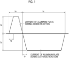
- the AC power source waveform of the electrochemical roughening treatment may use a sine wave, a square wave, a trapezoidal wave, and a triangular wave.
- the frequency is preferably 0.1-250 Hz.
- Fig. 1 is a graph showing an example of an alternating waveform current waveform diagram used for the electrochemical roughening treatment.
- ta represents an anode reaction time
- tc represents a cathode reaction time
- tp represents a time taken for the current to reach the peak from 1
- Ia represents the peak current on an anode cycle side
- Ic represents the peak current on a cathode cycle side.
- the time tp taken for the current to reach the peak from 0 is preferably 1-10 msec.
- a ratio tc/ta of the cathode reaction time tc to the anode reaction time ta of the aluminum plate is 1-20
- a ratio Qc/Qa of an electric quantity Qc at the time of the aluminum plate serving as a cathode to an electric quantity Qa at the time of the aluminum plate serving as an anode is 0.3-20
- the anode reaction time ta is 5-1000 msec.
- the current density is preferably 10-200 A/dm 2 in both of an anode cycle side Ia and a cathode cycle side Ic of the current in terms of the peak value of the trapezoidal wave.
- the value of Ic/Ia is preferably 0.3-20.
- the total amount of the electricity used for the anode reaction of the aluminum plate at the time when the electrochemical roughening is completed is preferably 25-1000 C/dm 2 .
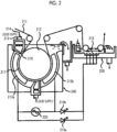
- a device illustrated in Fig. 2 can be used for the electrochemical roughening carried out using the alternating current.
- Fig. 2 is a side view illustrating an example of a radial type cell in the electrochemical roughening treatment carried out using the alternating current.
- the aluminum plate W is wound around the radial drum roller 52 disposed by being immersed in the main electrolytic cell 50 and is electrolyzed by the main poles 53a and 53b connected to the AC power source 51 in the transport process.
- the electrolytic solution 55 is supplied to the electrolytic solution passage 57 disposed between the radial drum roller 52 and the main pole 53a and between the radial drum roller 52 and the main pole 53b through the slit 56 from the electrolytic solution supply port 54.
- the aluminum plate W which has been treated in the main electrolytic cell 50 is electrolyzed in the auxiliary anode cell 60.
- the auxiliary anode 58 is disposed in the auxiliary anode cell 60 so as to face the aluminum plate W and the electrolytic solution 55 is supplied so as to flow through the space between the auxiliary anode 58 and the aluminum plate W.
- the amount of the aluminum plate to be dissolved in the second alkali etching treatment is preferably ⁇ 1.0 g/m 2 and more preferably 2.0-10 g/m 2 .
- the amount of the aluminum plate to be dissolved in the third alkali etching treatment and the fourth alkali etching treatment is preferably 0.01-0.8 g/m 2 and more preferably 0.05-0.3 g/m 2 .
- an acidic aqueous solution containing phosphoric acid, nitric acid, sulfuric acid, chromic acid, hydrochloric acid, or mixed acids obtained by mixing two or more of these acids is suitably used.
- the concentration of the acidic aqueous solution is preferably 0.5-60 mass%.
- the procedures of the anodization treatment step are not particularly limited as long as the above-described micropores are obtained, and known methods are exemplified.
- an aqueous solution containing e.g. sulfuric acid, phosphoric acid or oxalic acid can be used as an electrolytic cell.
- concentration of the sulfuric acid is in a range of 100-300 g/L.
- the conditions for the anodization treatment are appropriately set depending on the electrolytic solution.
- the liquid temperature is 5-70°C (preferably 10-60°C)
- the current density is 0.5-60 A/dm 2 (preferably 5-60 A/dm 2 )
- the voltage is 1-100 V (preferably 5-50 V)
- the electrolysis time is 1-100 sec (preferably 5-60 sec)
- the coating amount is 0.1-5 g/m 2 (preferably 0.2-3 g/m 2 ).
- the pore widening treatment is a treatment (pore diameter widening treatment) of widening the diameter (pore diameter) of micropores present in the anodized film formed by the above-described anodization treatment step.
- the pore widening treatment can be performed by bringing the aluminum plate obtained in the anodization treatment step into contact with an acid aqueous solution or an alkali aqueous solution.
- the method of bringing the aluminum plate into contact with the solution is not particularly limited, and examples thereof include an immersion method and a spray method.
- a back coat layer that contains an organic polymer compound described in JP1993-045885A ( JP-H05-045885A ) and an alkoxy compound of silicon described in JP1994-035174A ( JP-H6-035174A ) on the rear surface of the support as necessary.
- the present LPP precursor includes a water-soluble or a water-dispersible negative type image recording layer on a support.
- water-soluble means that ⁇ 0.5 g of a substance is dissolved in 100 g of water at 20°C, and the water-soluble layer may be a layer which is dissolved by an amount of ⁇ 0.5 g in 100 g of water at 20°C.
- water-dispersible means that a substance is uniformly dispersed in water at 20°C, and the water-dispersible layer indicates a layer which can be uniformly dispersed in water at 20°C.
- the image recording layer in the present LPP precursor is an image recording layer according to any of the following first to fifth aspects.
- An infrared absorbing agent, a polymerizable compound, and a polymerization initiator are contained.
- thermoplastic polymer particles are contained.
- polymer particles or a microgel is further contained.
- thermoplastic polymer particles are further contained.
- a microgel is further contained.
- the first aspect or the second aspect it is possible to obtain a LPP precursor that has excellent printing durability of a LPP to be obtained.
- the image recording layer is an image recording layer (hereinafter, also referred to as an "image recording layer C") contains an infrared absorbing agent and thermoplastic polymer particles.
- the image recording layer C contains an infrared absorbing agent and thermoplastic polymer particles.
- the constituent components of the image recording layer C will be described.
- the infrared absorbing agent contained in the image recording layer C a dye or a pigment having maximum absorption at a wavelength of 760-1,200 nm is preferable. A dye is more preferable.
- infrared absorbing dyes such as an azo dye, a metal complex salt azo dye, a pyrazolone azo dye, an anthraquinone dye, a phthalocyanine dye, a carbonium dye, a quinone imine dye, a polymethine dye, and a cyanine dye.
- infrared absorbing dyes having a water-soluble group are particularly preferable from the viewpoint of addition to the image recording layer C.
- infrared absorbing dyes are described below, but the present disclosure is not limited thereto.
- pigments commercially available pigments and pigments described in Color Index (C. I.) Handbook, "Latest Pigment Handbook” (edited by Japan Pigment Technology Association, 1977 ), “ Latest Pigment Application Technology” (CMC Publishing Co., Ltd., 1986 ), and “ Printing Ink Technology” (CMC Publishing Co., Ltd., 1984 ) can be used.
- the particle diameter of the pigment is preferably 0.01-1 ⁇ m and more preferably 0.01-0.5 ⁇ m.
- a known dispersion technique used to produce inks or toners can be used as a method of dispersing the pigment. The details are described in " Latest Pigment Application Technology” (CMC Publishing Co., Ltd., 1986 ).
- the content of the infrared absorbing agent is preferably 0.1-30 mass%, more preferably 0.25-25 mass%, and particularly preferably 0.5-20 mass% with respect to the total mass of the image recording layer. In a case where the content thereof is in the above-described range, excellent sensitivity is obtained without damaging the film hardness of the image recording layer.
- the glass transition temperature (Tg) of the thermoplastic polymer particles is preferably 60-250°C.
- the Tg of the thermoplastic polymer particles is more preferably 70-140°C and still more preferably 80-120°C.
- thermoplastic polymer particles having a Tg of ⁇ 60°C include thermoplastic polymer particles described in Research Disclosure No. 33303 on January, 1992, JP1997-123387A ( JP-H09-123387A ), JP1997-131850A ( JP-H09-131850A ), JP1997-171249A ( JP-H09-171249A ), JP1997-171250A ( JP-H09-171250A ), and EP931647B .
- polystyrene, styrene, a copolymer containing styrene and acrylonitrile, and polymethylmethacrylate are preferable.
- the average particle diameter of the thermoplastic polymer particles is preferably 0.005-2.0 ⁇ m from the viewpoints of the resolution and the temporal stability. This value is used as the average particle diameter in a case where two or more kinds of thermoplastic polymer particles are mixed with each other.
- the average particle diameter thereof is more preferably 0.01-1.5 ⁇ m and particularly preferably 0.05-1.0 ⁇ m.
- the polydispersity in a case where two or more kinds of thermoplastic polymer particles are mixed with each other is preferably ⁇ 0.2.
- the average particle diameter and the polydispersity are calculated according to a laser light scattering method.
- thermoplastic polymer particles may be used in combination of two or more kinds thereof. Specifically, at least two kinds of thermoplastic polymer particles with different particle sizes or at least two kinds of thermoplastic polymer particles with different glass transition temperatures (Tg) may be exemplified. In a case where two or more kinds of thermoplastic polymer particles are used in combination, coated-film curing properties of an image area are further improved and printing durability in a case where a LPP is obtained is further improved.
- thermoplastic polymer particles having the same particle size voids are present between the thermoplastic polymer particles to some extent, the curing properties of the coated-film are not desirable in some cases even in a case where the thermoplastic polymer particles are melted and solidified by image exposure. Meanwhile, in a case where thermoplastic polymer particles having different particle sizes are used, the void volume between the thermoplastic polymer particles can be decreased and thus the coated-film curing properties of the image area after image exposure can be improved.
- thermoplastic polymer particles having the same Tg are used, the thermoplastic polymer particles are not sufficiently melted and solidified and, accordingly, the coated-film curing properties are not desirable in some cases when an increase in temperature of the image recording layer resulting from image exposure is insufficient. Meanwhile, in a case where thermoplastic polymer particles having different glass transition temperatures (Tg) are used, the coated-film curing properties of the image area can be improved when an increase in temperature of the image recording layer resulting from image exposure is insufficient.
- Tg glass transition temperatures
- the Tg of at least one thermoplastic polymer particle is preferably ⁇ 60°C.
- a difference in Tg is preferably ⁇ 10°C and more preferably ⁇ 20°C.
- the content of the thermoplastic polymer particles having a Tg of ⁇ 60°C is preferably ⁇ 70 mass% with respect to the total amount of all thermoplastic polymer particles.
- the thermoplastic polymer particles may include a cross-linking group.
- the cross-linking group is thermally reacted due to heat generated by an image-exposed portion, cross-linking occurs between polymers, coated-film strength of an image area is improved, and printing durability becomes more excellent.
- a functional group in which any reaction may occur, is not limited as long as a chemical bond is formed, and examples thereof include an ethylenically unsaturated group that performs a polymerization reaction (such as acryloyl, methacryloyl, vinyl, or allyl); an isocyanate group that performs an addition reaction or a block body thereof, and a group having active hydrogen atoms as the reaction partners of these (such as amino, hydroxy, or carboxyl); an epoxy group that performs an addition reaction and amino, carboxyl or hydroxy as reaction partners thereof; a carboxyl group that performs a condensation reaction and hydroxy or amino; and an acid anhydride that performs a ring opening addition reaction and amino or hydroxy.
- a polymerization reaction such as acryloyl, methacryloyl, vinyl, or allyl
- an isocyanate group that performs an addition reaction or a block body thereof, and a group having active hydrogen atoms as the reaction partners of these (such as amino
- thermoplastic polymer particles having a cross-linking group include thermoplastic polymer fine particles having cross-linking groups such as acryloyl, methacryloyl, vinyl, allyl, epoxy, amino, hydroxy, carboxyl, isocyanate, acid anhydride, and a group protecting these. These cross-linking groups may be introduced to polymers at the time of polymerization of particle polymers or may be introduced using a polymer reaction after polymerization of particle polymers.
- a cross-linking group is introduced to a polymer at the time of polymerization of polymer particles, it is preferable that a monomer having a cross-linking group may be subjected to an emulsion polymerization or suspension polymerization.
- the monomer having a cross-linking group examples include allyl methacrylate, allyl acrylate, vinyl methacrylate, vinyl acrylate, glycidyl methacrylate, glycidyl acrylate, 2-isocyanate ethyl methacrylate or block isocyanate resulting from alcohol thereof, 2-isocyanate ethyl acrylate or block isocyanate resulting from alcohol thereof, 2-aminoethyl methacrylate, 2-aminoethyl acrylate, 2-hydroxyethyl methacrylate, 2-hydroxyethyl acrylate, acrylic acid, methacrylic acid, maleic anhydride, bifunctional acrylate, and bifunctional methacrylate.
- Examples of the polymer reaction used in a case where a cross-linking group is introduced after polymerization of polymer particles include polymer reactions described in WO96/034316A .
- Polymer particles may react with each other through a cross-linking group or the thermoplastic polymer particles may react with a polymer compound or a low-molecular weight compound added to the image recording layer.
- the content of the thermoplastic polymer particles is preferably 50-95 mass%, more preferably 60-90 mass%, and particularly preferably 70-85 mass% with respect to the total mass of the image recording layer.
- the image recording layer C may contain other components as necessary.
- a surfactant having a polyoxyalkylene group or a hydroxy group is preferably exemplified.
- a surfactant having a polyoxyalkylene group hereinafter, also referred to as a "POA group" or a hydroxy group
- a surfactant having a POA group or a hydroxy group can be suitably used, but an anionic surfactant or a non-ionic surfactant is preferable.
- anionic surfactants or non-ionic surfactants having a POA group or a hydroxy group anionic surfactants or non-ionic surfactants having a POA group are preferable.
- polyoxyethylene polyoxypropylene, or polyoxybutylene is preferable and polyoxyethylene is particularly preferable.
- the average degree of polymerization of an oxyalkylene group is preferably 2-50 and more preferably 2-20.
- the number of hydroxy groups is preferably 1-10 and more preferably 2-8.
- the number of terminal hydroxy groups in the oxyalkylene group is not included in the number of hydroxy groups.
- the anionic surfactant having a POA group is not particularly limited, and examples thereof include polyoxyalkylene alkyl ether carboxylates, polyoxyalkylene alkyl sulfosuccinates, polyoxyalkylene alkyl ether sulfuric acid ester salts, alkyl phenoxy polyoxyalkylene propyl sulfonates, polyoxyalkylene alkyl sulfophenyl ethers, polyoxyalkylene aryl ether sulfuric acid ester salts, polyoxyalkylene polycyclic phenylether sulfuric acid ester salts, polyoxyalkylene styryl phenyl ether sulfuric acid ester salts, polyoxyalkylene alkyl ether phosphoric acid ester salts, polyoxyalkylene alkyl phenyl ether phosphoric acid ester salts, and polyoxyalkylene perfluoroalkyl ether phosphoric acid ester salts.
- the anionic surfactant having a hydroxy group is not particularly limited, and examples thereof include hydroxy carboxylates, hydroxy alkyl ether carboxylates, hydroxy alkane sulfonates, fatty acid monoglyceride sulfuric acid ester salts, and fatty acid monoglyceride acid ester salts.
- the content of the surfactant having a POA group or a hydroxy group is preferably 0.05-15 mass% and more preferably 0.1-10 mass% with respect to the total mass of the image recording layer.
- a surfactant A-12 described below is a trade name of Zonyl FSP and available from Dupont.
- a surfactant N-11 described below is a trade name of Zonyl FSO 100 and available from Dupont.
- m and n in A-12 each independently is an integer of ⁇ 1.
- the image recording layer may contain an anionic surfactant that does not have a polyoxyalkylene group or a hydroxy group.
- the anionic surfactant is not particularly limited as long as the above-described purpose is achieved.
- the anionic surfactants alkyl benzene sulfonic acid or a salt thereof, alkyl naphthalene sulfonic acid or a salt thereof, (di)alkyl diphenyl ether (di)sulfonic acid or a salt thereof, or alkyl sulfuric acid ester salt is preferable.
- the addition amount of the anionic surfactant that does not have a polyoxyalkylene group or a hydroxy group is preferably 1-50 mass% and more preferably 1-30 mass% with respect to the total mass of the surfactant which has a polyoxyalkylene group or a hydroxy group.
- anionic surfactant that does not have a polyoxyalkylene group or a hydroxy group will be described, but the present disclosure is not limited thereto.
- a non-ionic surfactant that does not have a polyoxyalkylene group or a hydroxy group or a fluorine surfactant may be used.
- fluorine surfactants described in JP1987-170950A JP-S62-170950A are preferably used.
- the image recording layer may contain a hydrophilic resin.
- the hydrophilic resin include resins having hydrophilic groups such as hydroxy, hydroxyethyl, hydroxypropyl, amino, aminoethyl, aminopropyl, carboxy, carboxylate, sulfo, sulfonate, and phosphoric acid.
- hydrophilic resin examples include gum Arabic, casein, gelatin, a starch derivative, carboxy methyl cellulose and sodium salt thereof, cellulose acetate, sodium alginate, vinyl acetate-maleic acid copolymers, styrene-maleic acid copolymers, polyacrylic acids and salts of these, polymethacrylic acids and salts of these, a homopolymer and a copolymer of hydroxy ethyl methacrylate, a homopolymer and a copolymer of hydroxy ethyl acrylate, a homopolymer and a copolymer of hydroxy propyl methacrylate, a homopolymer and a copolymer of hydroxy propyl acrylate, a homopolymer and a copolymer of hydroxy butyl methacrylate, a homopolymer and a copolymer of hydroxy butyl acrylate, polyethylene glycols, hydroxy propylene polymers,
- the weight-average molecular weight of the hydrophilic resin is preferably ⁇ 2,000 from the viewpoints of obtaining sufficient coated-film strength or printing durability.
- the content of the hydrophilic resin is preferably 0.5-50 mass% and more preferably 1-30 mass% with respect to the total mass of the image recording layer.
- the image recording layer may contain inorganic particles other than those for forming unevenness described above.
- Preferred examples of the inorganic particles include silica, alumina, magnesium oxide, titanium oxide, magnesium carbonate, calcium alginate, and a mixture of these.
- the inorganic particles can be used for the purpose of improving coated-film strength.
- the average particle diameter of the inorganic particles is preferably 5 nm to 10 ⁇ m and more preferably 10 nm to 1 ⁇ m. In a case where the average particle diameter thereof is in the above described range, the thermoplastic polymer particles are stably dispersed, the film hardness of the image recording layer is sufficiently held, and a non-image area with excellent hydrophilicity in which printing stain is unlikely to occur can be formed.
- the inorganic particles are available as commercially available products such as a colloidal silica dispersion.
- the content of the inorganic particles is preferably 1.0-70 mass% and more preferably 5.0-50 mass% with respect to the total mass of the image recording layer.
- the image recording layer may contain a plasticizer in order to provide flexibility for a coated film.
- a plasticizer include polyethylene glycol, tributyl citrate, diethyl phthalate, dibutyl phthalate, dihexyl phthalate, dioctyl phthalate, tricresyl phosphate, tributyl phosphate, trioctyl phosphate, and tetrahydrofurfuryl oleate.
- the content of the plasticizer is preferably 0.1-50 mass% and more preferably 1-30 mass% with respect to the total mass of the image recording layer.
- a compound that starts or promotes a reaction of the thermally reactive functional group can be added to the image recording layer as necessary.
- a compound that starts or promotes a reaction of the thermally reactive functional group a compound that generates a radical or a cation by heating may be exemplified.
- the compound include a lophine dimer, a trihalomethyl compound, a peroxide, an azo compound, onium salts including diazonium salts and diphenyl iodonium salts, acyl phosphine, and imide sulfonate.
- the amount of the compound to be added to the image recording layer is preferably 1-20 mass% and more preferably 1-10 mass% with respect to the total mass of the image recording layer. In a case where the amount thereof is in the above-described range, the on-press developability is not degraded and excellent effects for starting or promoting a reaction are obtained.
- the image recording layer C is formed by dissolving or dispersing each of the above-described required components in a suitable solvent to prepare a coating solution, coating a support with the coating solution directly or through an undercoat layer.
- a suitable solvent water or a mixed solvent of water and an organic solvent is used, and a mixed solvent of water and an organic solvent is preferable from the viewpoint of the excellent surface state after coating. Since the amount of the organic solvent varies depending on the type of organic solvent, the amount thereof cannot be specified unconditionally, but the amount of the organic solvent in the mixed solvent is preferably 5-50 vol.%. Here, it is necessary that the amount of the organic solvent to be used is set such that the thermoplastic polymer particles are not aggregated.
- the concentration of solid contents of the image recording layer coating solution is preferably 1-50 mass%.
- a water-soluble organic solvent is preferable.
- an alcohol solvent such as methanol, ethanol, propanol, isopropanol, or 1-methoxy-2-propanol
- a ketone solvent such as acetone or methyl ethyl ketone
- a glycol ether solvent such as ethylene glycol dimethyl ether, ⁇ -butyrolactone, N,N-dimethylformamide, N,N-dimethylacetamide, tetrahydrofuran, and dimethylsulfoxide.
- an organic solvent having a boiling point of ⁇ 120°C and a solubility (amount of a solvent to be dissolved in 100 g of water) of ⁇ 10 g in water is preferable and an organic solvent having a solubility of ⁇ 20 g is more preferable.
- a coating method of the image recording layer coating solution various methods can be used. Examples of the methods include a bar coater coating method, a rotary coating method, a spray coating method, a curtain coating method, a dip coating method, an air knife coating method, a blade coating method, and a roll coating method.
- the coating amount (solid content) of the image recording layer on the support obtained after the coating and the drying varies depending on the purpose thereof, but is preferably 0.5-5.0 g/m 2 and more preferably 0.5-2.0 g/m 2 .
- the present LPP precursor may be provided with an undercoat layer between the image recording layer and the support as necessary. Since bonding of the support to the image recording layer becomes stronger in an exposed portion and the support is easily separated from the image recording layer in an unexposed portion, the undercoat layer contributes to improvement of on-press developability without degrading the printing durability. Further, in a case of infrared laser exposure, the undercoat layer functions as a heat insulating layer so that a degradation in sensitivity due to heat, generated by exposure, being diffused in the support is prevented.
- Examples of eth compound used for the undercoat layer include a silane coupling agent having an ethylenic double bond reaction group, which can be added and polymerized, described in JP1998-282679A ; and a phosphorous compound having an ethylenic double bond reaction group described in JP1990-304441A .
- Preferred examples thereof include polymer compounds having an adsorptive group which can be adsorbed to the surface of the support, a hydrophilic group, and a cross-linking group, as described in JP2005-125749A and JP2006-188038A .
- a copolymer of a monomer having an adsorptive group, a monomer having a hydrophilic group, and a monomer having a cross-linking group is preferable.
- a copolymer of a monomer having an adsorptive group such as a phenolic hydroxy group, a carboxy group, -PO 3 H 2 , -OPO 3 H 2 , -CONHSO 2 -, -SO 2 NHSO 2 -, or -COCH 2 COCH 3
- a monomer having a hydrophilic group such as a sulfo group
- a monomer having a polymerizable cross-linking group such as a methacryl group or an allyl group.
- the polymer compound may include a cross-linking group introduced by forming salts between a polar substituent of the polymer compound and a compound that includes a substituent having the opposite charge and an ethylenically unsaturated bond.
- monomers other than the monomers described above, preferably hydrophilic monomers may be further copolymerized.
- the content of the ethylenically unsaturated bond in the polymer compound for an undercoat layer is preferably 0.1-10.0 mmol and more preferably 2.0-5.5 mmol with respect to 1 g of the polymer compound.
- the weight-average molecular weight of the polymer compound for an undercoat layer is preferably ⁇ 5,000 and more preferably 10,000-300,000.
- the undercoat layer may contain, for example, a chelating agent, a secondary or tertiary amine, a polymerization inhibitor, an amino group, and a compound that includes an amino group or a functional group having polymerization inhibiting ability and a group interacting with the surface of an aluminum support (for example, 1,4-diazabicyclo[2.2.2]octane (DABCO), 2,3,5,6-tetrahydroxy-p-quinone, chloranil, sulfophthalic acid, hydroxyethyl ethylene diamine triacetic acid, dihydroxyethyl ethylene diamine diacetic acid, or hydroxyethyl imino diacetic acid) in addition to the compounds for an undercoat layer described above.
- a chelating agent for example, 1,4-diazabicyclo[2.2.2]octane (DABCO), 2,3,5,6-tetrahydroxy-p-quinone, chloranil, sulfophthalic acid, hydroxye
- the undercoat layer is applied according to a known method.
- the coating amount of the undercoat layer after being dried is preferably 0.1-100 mg/m 2 and more preferably 1-30 mg/m 2 .
- a protective layer may be provided on the image recording layer as necessary.
- the protective layer has a function of suppressing a reaction of inhibiting image formation through oxygen blocking, a function of preventing generation of damage to the image recording layer, and a function of preventing ablation at the time of high illuminance laser exposure.
- the protective layer is applied according to a known method.
- the coating amount of the protective layer after the drying is preferably 0.01-10 g/m 2 , more preferably 0.02-3 g/m 2 , and particularly preferably 0.02-1 g/m 2 .
- the LPP precursor can be produced by applying a coating solution of each configuration layer according to a typical method, performing drying, and forming each configuration layer.
- the coating solution can be applied according to a die coating method, a dip coating method, an air knife coating method, a curtain coating method, a roller coating method, a wire bar coating method, a gravure coating method, or a slide coating method.
- a method of producing the present LPP precursor is not particularly limited, but it is preferable that the method thereof includes a step of forming the image recording layer on the aluminum support after one or more days from an anodization treatment performed thereon.
- the development delay resistance becomes further excellent even though the detailed mechanism is not clear.
- the method of producing the present LPP precursor from the viewpoints of the development delay resistance, it is more preferable to use an aluminum support after three days to 1.6 years from an anodization treatment performed thereon and still more preferable to use an aluminum support after 7 days to 1 year from an anodization treatment performed thereon.
- the method of producing the present LPP precursor includes a step of forming the undercoat layer on the aluminum support after one or more days from an anodization treatment performed thereon.
- the present LPP precursor laminate is a laminate obtained by laminating present LPP precursors, and a laminate which is obtained by laminating a plurality of the present LPP precursors, in which the outermost layer on the surface where the image recording layer is provided and the outermost layer on the surface on the opposite side of the surface where the image recording layer is provided are laminated by being directly brought into contact with each other, is preferable.
- the present LPP precursor laminate is a laminate obtained by laminating a plurality of sheets of present LPP precursors without interposing interleaving paper therebetween.
- the number of sheets of laminated precursors is not particularly limited, but is preferably 2-500 sheets.
- the LPP precursor laminate according to the present disclosure has excellent performance in any of adhesiveness, scratches, or bruises due to the specific surface roughness of the present LPP precursor, and dislocation in stacking of LPP precursors is unlikely to occur.
- the present LPP laminate is a laminate obtained by laminating the present LPPs described below.
- the present LPP laminate is formed by staking a plurality of obtained LPPs and allowing the stack to stand at an appropriate location.
- the present LPP laminate has excellent performance in any of adhesiveness, scratches, or bruises due to the specific surface roughness of the present LPP, and dislocation in stacking of LPPs is unlikely to occur.
- the present LPP is a LPP obtained by plate-making the present LPP precursor.
- the plate-making method of the present LPP is not particularly limited as long as the method is a method of plate-making the present LPP precursor, and the method is a method of plate-making the LPP using the present LPP precursor and performing printing, and it is preferable that the method includes a step of image-exposing the present LPP precursor (also referred to as an "image-exposure step”); and a step of supplying at least any of printing ink or dampening water and removing an unexposed portion of an image recording layer on a printing press to prepare a LPP (also referred to as a "development treatment step").
- a step of image-exposing the present LPP precursor also referred to as an "image-exposure step”
- a step of supplying at least any of printing ink or dampening water and removing an unexposed portion of an image recording layer on a printing press to prepare a LPP also referred to as a "development treatment step”
- the present lithographic printing method is a method of plate-making the LPP using the present LPP precursor and performing printing, and it is preferable that the method includes a step of image-exposing the present LPP precursor (also referred to as an "image-exposure step”); a step of supplying at least any of printing ink or dampening water and removing an unexposed portion of an image recording layer on a printing press to prepare a LPP (also referred to as a "development treatment step”); and a step of performing printing using the obtained LPP (also referred to as a "printing step”).
- a step of image-exposing the present LPP precursor also referred to as an "image-exposure step”
- a step of supplying at least any of printing ink or dampening water and removing an unexposed portion of an image recording layer on a printing press to prepare a LPP also referred to as a "development treatment step”
- a step of performing printing using the obtained LPP also referred to as a "printing step”
- the development treatment step is performed without performing the image exposure step in a case of the key plate precursor.
- the image exposure of the LPP precursor can be performed in conformity with an image exposure operation for a typical LPP precursor.
- the image exposure is performed by laser exposure through e.g. a transparent original picture having a line image or a halftone image or by laser beam scanning using digital data.
- the wavelength of a light source is preferably 700-1,400 nm.
- a solid-state laser or a semiconductor laser that radiates infrared rays is preferable.
- the output of the infrared laser is preferably ⁇ 100 mW
- the exposure time per one pixel is preferably ⁇ 20 ⁇ s
- the irradiation energy quantity is preferably 10-300 mJ/cm 2 .
- the exposure mechanism may be any of an internal drum system, an external drum system, and a flat bed system.
- the image exposure can be performed using a plate setter according to a usual method.
- the development step can be performed using a typical method.
- a printing ink receiving portion having a lipophilic surface is formed by the image recording layer cured by light exposure in the exposed portion of the image recording layer in a case where at least any of dampening water or printing ink is supplied to the image-exposed LPP precursor on a printing press.
- a non-cured image recording layer is dissolved or dispersed by supplied at least any of dampening water or printing ink and then removed, a hydrophilic surface is exposed to the portion.
- dampening water is exposed and adheres to the hydrophilic surface, the printing ink is impressed on the image recording layer of the exposed region, and then the printing is started.
- dampening water or printing ink may be initially supplied to the surface of the LPP precursor, but it is preferable that dampening water is initially supplied thereto by infiltrating dampening water so that the on-press developability is promoted.
- the printing using the obtained LPP can be performed according to a typical method.
- the printing can be performed by supplying desired printing ink and dampening water, as necessary, to the LPP.
- the amount of the printing ink and dampening water to be supplied is not particularly limited and may be appropriately set according to the desired printing.
- the method of supplying the printing ink and dampening water to the LPP is not particularly limited and a known method can be used.
- a LPP in the present LPP precursor, can be prepared by performing a development treatment using a developer by appropriately selecting a binder polymer serving as a constituent component of the image recording layer.
- the method of plate-making a present LPP includes a step of image-exposing the present LPP precursor (also referred to as an "image exposure step") and a development step of supplying a developer having a pH of 2-14 and removing the unexposed portion (also referred to as a "developer development step”).
- the plate-making method is also referred to as a "developer treatment system”.
- the lithographic printing method according to the present disclosure includes a step of image-exposing the present LPP precursor (also referred to as an "image exposure step”); a development step of supplying a developer having a pH of 2-14 and removing the unexposed portion (also referred to as a “developer development step”); and a step of performing printing using the obtained LPP (hereinafter, also referred to as a "printing step”).
- the image exposure step in the developer treatment system is the same as the image exposure step in the on-press development system described above.
- a LPP in the present LPP precursor, can be prepared by performing a development treatment using a developer by appropriately selecting a binder polymer serving as a constituent component of the image recording layer.
- the development treatment carried out using a developer includes an aspect (also referred to as a simple development treatment) of using a developer having a pH of 2-11 which contains at least one compound selected from a surfactant and a water-soluble polymer compound.
- the development treatment and a gum liquid treatment step can be simultaneously performed using a method of allowing a developer to contain a water-soluble polymer compound as necessary.
- a post-water washing step is not particularly required, and a drying step can be performed after the development treatment and the gum liquid treatment are performed using one liquid and one step. Therefore, it is preferable that the development treatment using a developer is performed according to the method of preparing a LPP, including a step of performing a development treatment on the image-exposed LPP precursor using a developer having a pH of 2-11. After the development treatment, it is preferable that the drying is performed after the excessive developer is removed using a squeeze roller.
- the development treatment and the gum liquid treatment are performed using one liquid and one step.
- the development treatment and the gum liquid treatment are performed using one liquid and one step.
- the development treatment and the gum liquid treatment are performed in one step using one liquid without separately performing the development treatment and the gum liquid treatment as individual steps.
- the development treatment can be suitably performed using an automatic development treatment device provided with developer supply means and a rubbing member.
- an automatic development treatment device provided with a rotary brush roll is particularly preferable.
- an automatic development treatment device includes means for removing the excessive developer, such as a squeeze roller, and drying means such as a hot air device on the rear side of the development treatment device. Further, the automatic development treatment device may include pre-heating means for performing a heating treatment on the image-exposed LPP precursor on the front side of the development treatment means.
- the treatment carried out using such an automatic development treatment device has an advantage that it is no longer necessary to deal with development scum derived from an image recording layer (a protective layer in a case where the LPP precursor has a protective layer) which is generated in a case of a so-called on-press development treatment.
- a method of allowing sponge or absorbent cotton to contain an aqueous solution, performing treatment while rubbing the entire plate surface, and drying the aqueous solution after the treatment is completed is suitably exemplified as the development treatment method.
- an immersion treatment for example, a method of immersing the LPP precursor in a tray or a deep tank containing an aqueous solution therein for approximately 60 seconds, stirring the solution, and drying the aqueous solution while rubbing the plate surface with absorbent cotton or sponge is suitably exemplified.
- a device capable of simplifying the structure and the steps is used in the development treatment.
- a protective layer is removed by the pre-water washing step, development is performed using an alkali developer having a high pH, an alkali is removed by the post-water washing step, the gum treatment is performed by a gum coating step, and drying is performed by a drying step.
- development and gum coating can be simultaneously performed using one liquid. Therefore, the post-water washing step and the gum treatment step can be omitted, and it is preferable that the drying step is performed as necessary after development and gum coating (gum liquid treatment) are performed using one liquid.
- removal of the protective layer, development, and gum coating are simultaneously performed using one liquid without performing the pre-water washing step. Further, it is preferable that the excessive developer is removed using a squeeze roller after the development and the gum coating and then drying is performed.
- the development treatment may be performed according to a method of performing immersion in a developer once or a method of performing immersion twice or more times. Among these, a method of performing immersion in the developer once or twice is preferable.
- the immersion may be carried out by passing the exposed LPP precursor through a developer tank in which the developer is stored or spraying the developer onto the plate surface of the exposed LPP precursor using e.g. a spray.
- the development treatment is performed using one liquid (one liquid treatment) even in a case where the LPP precursor is immersed in the developer twice or more times or in a case where the LPP precursor is immersed, twice or more times, in the same developer as described above or a developer (fatigue liquid) obtained by dissolving or dispersing components of the image recording layer using the developer and the development treatment.
- the development treatment can be performed by immersing the LPP precursor which has been subjected to the exposure treatment and rubbing the plate surface with brushes or pumping up the treatment liquid added to an external tank using a pump, spraying the developer from a spray nozzle, and rubbing the plate surface with brushes at a temperature of preferably 0-60°C and more preferably 15-40°C, according to a conventional method.
- These development treatments can be continuously performed plural times.
- the development treatment can be performed by pumping up the developer added to an external tank using a pump, spraying the developer from a spray nozzle, rubbing the plate surface with brushes, spraying the developer from the spray nozzle again, and rubbing the plate surface with the brushes.
- the development treatment is performed using an automatic development treatment device, since the developer becomes fatigued as the treatment amount increases, it is preferable that the treatment capability is recovered using a replenisher or a fresh developer.
- the development treatment can also be performed using a gum coater or an automatic development treatment device which has been known to be used for a presensitized (PS) plate and computer-to-plate (CTP) in the related art.
- an automatic development treatment device for example, any system from among a system of performing the treatment by pumping the developer added to a developer tank or the developer added to an external tank using a pump and spraying the developer from a spray nozzle, a system of performing the treatment by immersing a printing plate in a tank filled with the developer and transporting the printing plate using a guide roller in the developer, and a so-called disposable treatment system, which is a system of performing the treatment by supplying the substantially unused developer by an amount required for each plate can be employed.
- a rubbing mechanism using brushes or a molleton is provided.
- commercially available automatic development treatment devices (Clean Out Unit C85/C125, Clean-Out Unit + C85/120, FCF 85V, FCF 125V, FCF News (manufactured by Glunz & Jensen); and Azura CX85, Azura CX125, and Azura CX150 (manufactured by AGFA GRAPHICS) can be used.
- a device in which a laser exposure portion and an automatic development treatment device portion are integrally incorporated can also be used.
- the pH of the developer is preferably 2-11, more preferably 5-9, and still more preferably 7-9. From the viewpoints of the developability and the dispersibility of the image recording layer, it is advantageous that the value of the pH is set to be higher. However, from the viewpoints of the printability and suppression of stain, it is effective that the value of the pH is set to be low.
- the pH is a value obtained by performing measurement at 25°C using a pH meter (model number: HM-31, manufactured by DKK-TOA Corporation).
- the developer may contain a surfactant such as an anionic surfactant, a non-ionic surfactant, a cationic surfactant, or an amphoteric surfactant.
- a surfactant such as an anionic surfactant, a non-ionic surfactant, a cationic surfactant, or an amphoteric surfactant.
- the developer contains at least one selected from an anionic surfactant and an amphoteric surfactant.
- the developer contains a non-ionic surfactant and more preferable that the developer contains at least one selected from a non-ionic surfactant, an anionic surfactant, and an amphoteric surfactant.
- anionic surfactant examples include compounds represented by Formula (I). R 1 -Y 1 -X 1 ... (I)
- R 1 is alkyl, cycloalkyl, alkenyl, aralkyl, or aryl which may have a substituent.
- C 1-20 -alkyl is preferable, and preferred specific examples thereof include methyl, ethyl, propyl, n-butyl, sec-butyl, hexyl, 2-ethylhexyl, octyl, decyl, dodecyl, hexadecyl, and stearyl.
- the cycloalkyl group may be monocyclic or polycyclic.
- monocyclic cycloalkyl group monocyclic C 3-8 -cycloalkyl is preferable, and cyclopropyl, cyclopentyl, cyclohexyl, or cyclooctyl is more preferable.
- Preferred examples of the polycyclic cycloalkyl group include adamantyl, norbornyl, isobornyl, camphanyl, dicyclopentyl, ⁇ -pinel, and tricyclodecanyl.
- alkenyl group for example, C 2-20 -alkenyl is preferable, and preferred specific examples thereof include vinyl, allyl, butenyl, and cyclohexenyl.
- aralkyl group for example, C 7-12 -aralkyl is preferable, and preferred specific examples thereof include benzyl, phenethyl, and naphthylmethyl.
- aryl group for example, C 6-15 -aryl is preferable, and preferred specific examples thereof include phenyl, tolyl, dimethylphenyl, 2,4,6-trimethylphenyl, naphthyl, anthryl, and 9,10-dimethoxyanthryl.
- a monovalent nonmetallic atom group excluding a hydrogen atom is used, and preferred examples thereof include halogen (F, Cl, Br, or I), hydroxy, alkoxy, aryloxy, acyl, amide, ester, acyloxy, carboxy, carboxylic acid anion, and sulfonic acid anion.
- alkoxy group in the substituent methoxy, ethoxy, propyloxy, isopropyloxy, butyloxy, pentyloxy, hexyloxy, dodecyloxy, stearyloxy, methoxyethoxy, poly(ethyleneoxy), and poly(propyleneoxy), respectively having 1-40 carbon atoms, are preferable; and these groups respectively having 1-20 carbon atoms are more preferable.
- Examples of the aryloxy group include phenoxy, tolyloxy, xylyloxy, mesityloxy, cumenyloxy, methoxyphenyloxy, ethoxyphenyloxy, chlorophenyloxy, bromophenyloxy, and naphthyloxy, respectively having 6-18 carbon atoms.
- Examples of the acyl group include acetyl, propanoyl, butanoyl, benzoyl, and naphthoyl, respectively having 2-24 carbon atoms.
- Examples of the amide group include acetamide, propionic acid amide, dodecanoic acid amide, palmitic acid amide, stearic acid amide, benzoic acid amide, and naphthoic acid amide, respectively having 2-24 carbon atoms.
- Examples of the acyloxy group include acetoxy, propanoyloxy, benzoyloxy, and naphthoyloxy, respectively having 2-20 carbon atoms.
- Examples of the ester group include methyl ester, ethyl ester, propyl ester, hexyl ester, octyl ester, dodecyl ester, and stearyl ester, respectively having 1-24 carbon atoms.
- the substituent may be formed by combining two or more substituents described above.
- X 1 represents a sulfonate group, a sulfate monoester group, a carboxylate group, or a phosphate group.
- Y 1 represents a single bond, -C n H 2n -, -C n-m H 2(n-m) OC m H 2m -, -O-(CH 2 CH 2 O) n -, -O-(CH 2 CH 2 CH 2 O) n -, -CO-NH-, or a divalent linking group formed by combining two or more of these and satisfies the expressions of "n ⁇ 1" and "n ⁇ m ⁇ 0".
- a compound of Formula (I-A) or (I-B) is preferable.
- R A1 -R A10 each independently are H or alkyl
- nA is an integer of 1-3
- X A1 and X A2 each independently are a sulfonate group, a sulfate monoester group, a carboxylate group, or a phosphate group
- Y A1 and Y A2 each independently are a single bond, -C n H 2n -, -C n-m H 2(n-m) OC m H 2m -, -O-(CH 2 CH 2 O) n -, -O-(CH 2 CH 2 CH 2 O) n -, -CO-NH-, or a divalent linking group formed by combining two or more of these and satisfy the inequations of "n ⁇ 1" and "n ⁇ m ⁇ 0".
- the total number of carbon atoms in R A1 -R A5 or R A6 -R A10 and Y A each independently are H or alkyl
- the total number of carbon atoms in R A1 -R A5 and Y 1A or R A6 -R A10 and Y A2 in the compound represented by Formula (I-A) or (I-B) is preferably ⁇ 25 and more preferably 4-20.
- the structure of the above-described alkyl group may be linear or branched.
- X A1 and X A2 in the compound of Formula (I-A) or (I-B) represent a sulfonate group or a carboxylate group.
- the salt structure in X A1 and X A2 is preferable from the viewpoint that the solubility of the alkali metal salt in a water-based solvent is particularly excellent.
- a sodium salt or a potassium salt is particularly preferable.
- the compounds described in paragraphs [0023]-[0028] of JP2006-065321A can be suitably used.
- amphoteric surfactant used for the developer is not particularly limited, and examples thereof include an amine oxide-based surfactant such as alkyl dimethylamine oxide; a betaine-based surfactant such as alkyl betaine, fatty acid amide propyl betaine, or alkyl imidazole; and an amino acid-based surfactant such as sodium alkylamino fatty acid.
- an amine oxide-based surfactant such as alkyl dimethylamine oxide
- a betaine-based surfactant such as alkyl betaine, fatty acid amide propyl betaine, or alkyl imidazole
- an amino acid-based surfactant such as sodium alkylamino fatty acid.
- alkyl dimethylamine oxide which may have a substituent alkyl carboxy betaine which may have a substituent, or alkyl sulfobetaine which may have a substituent is preferably used.
- alkyl dimethylamine oxide which may have a substituent
- alkyl carboxy betaine which may have a substituent
- alkyl sulfobetaine which may have a substituent
- JP2008-203359A compounds represented by Formulae (I), (II), and (VI) in paragraph [0028] of JP2008-276166A , and compounds described in paragraphs [0022]-[0029] of JP2009-047927A .
- amphoteric ion-based surfactant used for the developer a compound represented by formula (1) or a compound represented by Formula (2) is preferable.
- R 1 and R 11 each independently C 8-20 -alkyl or alkyl that contains a linking group having 8-20 carbon atoms.
- R 2 , R 3 , R 12 , and R 13 each independently are H, alkyl, or a group containing an ethylene oxide structure.
- R 4 and R 14 each independently are a single bond or an alkylene group.
- two groups from among R 1 -R 4 may be bonded to each other to form a ring structure
- two groups from among R 11 -R 14 may be bonded to each other to form a ring structure.
- the hydrophobic portion becomes bigger as the total number of carbon atoms increases, and the solubility in a water-based developer is decreased.
- the solubility is improved by mixing an organic solvent such as alcohol that assists dissolution with water as a dissolution assistant, but the surfactant cannot be dissolved within a proper mixing range in a case where the total number of carbon atoms becomes extremely large.
- the total number of carbon atoms of R 1 -R 4 or R 11 -R 14 is preferably 10-40 and more preferably 12-30.
- the alkyl group containing a linking group represented by R 1 or R 11 has a structure in which a linking group is present between alkyl groups.
- the structure can be represented by "-alkylene group-linking group-alkyl group".
- the linking group include an ester bond, a carbonyl bond, and an amide bond.
- the structure may have two or more linking groups, but it is preferable that the structure has one linking group, and an amide bond is particularly preferable as the linking group.
- the total number of carbon atoms of the alkylene group bonded to the linking group is preferably 1-5.
- the alkylene group may be linear or branched, but a linear alkylene group is preferable.
- the number of carbon atoms of the alkyl group bonded to the linking group is preferably 3-19, and the alkyl group may be linear or branched, but a linear alkyl group is preferable.
- R 2 or R 12 is an alkyl group
- the number of carbon atoms thereof is preferably 1-5 and particularly preferably 1-3.
- the alkyl group may be linear or branched, but a linear alkyl group is preferable.
- R 3 or R 13 is an alkyl group
- the number of carbon atoms thereof is preferably 1-5 and particularly preferably 1-3.
- the alkyl group may be linear or branched, but a linear alkyl group is preferable.
- R a is a single bond, an oxygen atom, or a divalent organic group (preferably having ⁇ 10 carbon atoms)
- R b is H or an organic group (preferably having ⁇ 10 carbon atoms)
- n is an integer of 1-10.
- R 4 and R 14 is an alkylene group
- the number of carbon atoms thereof is preferably 1-5 and particularly preferably 1-3.
- the alkylene group may be linear or branched, but linear alkylene is preferable.
- the compound of Formula (1) or (2) has preferably an amide bond and more preferably an amide bond as a linking group represented by R 1 or R 11 .
- the compound of Formula (1) or (2) can be synthesized according to a known method. Further, commercially available products may be used. Examples of the commercially available products of the compound represented by Formula (1) include SOFRAZOLINE LPB, SOFTAZOLINE LPB-R, and VISTA MAP (manufactured by Kawaken Fine Chemicals Co., Ltd.), and TAKESAAF C-157L (manufactured by TAKEMOTO OIL & FAT Co., Ltd.). Examples of the commercially available products of the compound represented by Formula (2) include SOFTAZOLINE LAO (manufactured by Kawaken Fine Chemicals Co., Ltd.) and AMOGEN AOL (manufactured by DKS Co., Ltd.).
- amphoteric ion-based surfactant may be used alone or in combination of two or more kinds thereof in a developer.
- non-ionic surfactant examples include polyoxyethylene alkyl ethers, polyoxyethylene alkyl phenyl ethers, polyoxyethylene polystyryl phenyl ether, glycerin fatty acid partial esters, sorbitan fatty acid partial esters, pentaerythritol fatty acid partial esters, propylene glycol monofatty acid ester, sucrose fatty acid partial ester, polyoxyethylene sorbitan fatty acid partial esters, polyoxyethylene sorbitol fatty acid partial esters, polyethylene glycol fatty acid esters, polyglycerin fatty acid partial esters, polyoxyethylene glycerin fatty acid partial esters, polyoxyethylene diglycerins, fatty acid diethanolamides, N,N-bis-2-hydroxyalkylamines, polyoxyethylene alkylamine, triethanolamine fatty acid ester, trialkylamine oxide, polyoxyethylene alkyl phenyl ethers, and polyoxyethylene-polyoxypropylene block cop
- acetylene glycol-based and acetylene alcohol-based oxyethylene adducts, and fluorine-based surfactants can also be used. These surfactants can be used in combination of two or more kinds thereof.
- non-ionic surfactant examples include a non-ionic aromatic ether-based surfactant represented by Formula (N1).
- N1 a non-ionic aromatic ether-based surfactant represented by Formula (N1).
- X N represents an aromatic group which may have a substituent
- Y N isa single bond or C 1-10 -alkylene
- a 1 and A 2 are different groups and represent any of -CH 2 CH 2 O- or -CH 2 CH(CH 3 )O-
- nB and mB each independently are an integer of 0-100, where both of nB and mB are not 0 at the same time. Further, both of nB and mB are not 1 at the same time in a case where any of nB or mB is 0.
- examples of the aromatic group as X N include phenyl, naphthyl, and anthranyl. These aromatic groups may have a substituent.
- substituent an organic group having 1-100 carbon atoms is exemplified. Further, in the formula, this may represent a random or block copolymer in a case where both of A and B are present.
- organic group having 1-100 carbon atoms include fatty acid hydrocarbon groups and aromatic hydrocarbon groups, which may be saturated or unsaturated and linear or branched, such as alkyl, alkenyl, alkynyl, aryl, aralkyl, alkoxy, aryloxy, N-alkylamino, a N,N-dialkylamino, N-arylamino, N,N-diarylamino, N-alkyl-N-arylamino, acyloxy group, carbamoyloxy, N-alkylcarbamoyloxy, N-arylcarbamoyloxy, N,N-dialkylcarbamoyloxy, N,N-diarylcarbamoyloxy, N-alkyl-N-arylcarbamoyloxy, acylamino, N-alkylacylamino, N-arylacylamino, acyl, alkoxycarbonylamino, alk
- non-ionic surfactants compounds described in paragraphs [0030]-[0040] of JP2006-065321A can also be suitably used.
- the cationic surfactant is not particularly limited, and known surfactants of the related art can be used. Examples thereof include alkylamine salts, quaternary ammonium salts, alkylimidazolinium salts, polyoxyethylene alkylamine salts, and a polyethylene polyamine derivative.
- the surfactant may be used alone or in combination of two or more kinds thereof.
- the content of the surfactant is preferably 1-25 mass%, more preferably 2-20 mass%, still more preferably 3-15 mass%, and particularly preferably 5-10 mass% with respect to the total mass of the developer.
- the scratch and stain resistance is excellent
- the dispersibility of the development scum is excellent
- the ink impressing property of the LPP to be obtained is excellent.
- the developer may contain a water-soluble polymer compound.
- soybean polysaccharides modified starch, arabic gum, dextrin
- a fiber derivative such as carboxymethyl cellulose, carboxyethyl cellulose, or methyl cellulose
- pullulan such as carboxymethyl cellulose, carboxyethyl cellulose, or methyl cellulose
- pullulan such as carboxymethyl cellulose, carboxy
- soybean polysaccharides those which have been known in the related art can be used.
- SOYAFIBE trade name, manufactured by FUJI OIL, CO., LTD.
- various grades of products can be used.
- Preferred examples thereof include products in which the viscosity of a 10 mass% aqueous solution is 10-00 mPa ⁇ s.
- starch of Formula (III) is preferable. Any of starch such as corn, potato, tapioca, rice, or wheat can be used as the starch of Formula (III).
- the modification of the starch can be performed according to a method of decomposing 5-30 glucose residues per one molecule with an acid or an enzyme and adding oxypropylene to an alkali.
- the etherification degree (degree of substitution) is 0.05-1.2 per glucose unit, n is an integer of 3-30, and m is an integer of 1-3.
- soybean polysaccharides modified starch, arabic gum, dextrin, carboxymethyl cellulose, and polyvinyl alcohol are particularly preferable.
- the water-soluble polymer compound can be used in combination of two or more kinds thereof.
- the content of the water-soluble polymer compound is preferably ⁇ 3 mass% and more preferably ⁇ 1 mass% with respect to the total mass of the developer. In a case where the content thereof is in the above-described range, the viscosity of the developer is moderate, and deposition of development scum on a roller member of an automatic development treatment device can be suppressed.
- the developer used in the present disclosure may contain a wetting agent, a preservative, a chelate compound, an antifoaming agent, an organic acid, an organic solvent, an inorganic acid, and an inorganic salt in addition to those described above.
- Suitable examples of the wetting agent include ethylene glycol, propylene glycol, triethylene glycol, butylene glycol, hexylene glycol, diethylene glycol, dipropylene glycol, glycerin, trimethylolpropane, and diglycerin.
- the wetting agent may be used alone or in combination of two or more kinds thereof.
- the content of the wetting agent is preferably 0.1-5 mass% with respect to the total mass of the developer.
- Preferred examples of the preservative include phenol and a derivative thereof, formalin, an imidazole derivative, a sodium dehydroacetate, 4-isothiazoline-3-one derivative, benzoisothiazolin-3-one, 2-methyl-4-isothiazolin-3-one, a guanidine derivative, derivatives of quaternary ammonium salts, pyridine, quinoline, and guanidine, diazine, a triazole derivative, oxazole, an oxazole derivative, nitrobromo alcohol-based 2-bromo-2-nitropropane-1,3-diol, 1,1-dibromo-1-nitro-2-ethanol, and 1,1-dibromo-1-nitro-2-propane.
- the amount of the preservative to be added is an amount of stably exhibiting the efficacy for bacterial, molds or yeasts, and is preferably 0.01-4 mass% with respect to the total mass of the developer even though the amount thereof varies depending on the type of bacteria, molds, and the yeasts. Further, it is preferable that the preservative is used in combination of two or more kinds thereof so as to be effective for sterilizing various molds.
- the chelate compound examples include ethylenediamine tetraacetic acid, diethylenetriamine pentaacetic acid, triethylenetetraminehexaacetic acid, hydroxyethylethylenediamine triacetic acid, organic phosphonic acids such as 1-hydroxyethane-1,1-diphosphonic acid, and aminotri(methylenephosphonic acid), and potassium and sodium salts of these acids; and nitrilotriacetic acid and a sodium salt thereof;.
- a salt of an organic amine is effectively used in place of a sodium salt or a potassium salt of a chelating agent.
- a chelating agent which is stably present in the composition of the treatment liquid and does not disturb the printability is preferable as the chelating agent.
- the content of the chelating agent is preferably 0.001-1.0 mass% with respect to the total mass of the developer.
- a typical silicone-based self-emulsifying type compound, an emulsifying type compound, a non-ionic compound having a hydrophilic-lipophilic balance (HLB) of 5 or less can be used.
- a silicone antifoaming agent is preferable.
- a silicone-based surfactant is regarded as an antifoaming agent.
- the content of the antifoaming agent is suitably 0.001-1.0 mass% with respect to the total mass of the developer.
- organic acid examples include citric acid, acetic acid, oxalic acid, malonic acid, salicylic acid, caprylic acid, tartaric acid, malic acid, lactic acid, levulinic acid, p-toluenesulfonic acid, xylenesulfonic acid, phytic acid, and organic phosphonic acid.
- the organic acid can be used in the form of an alkali metal salt or ammonium salt thereof.
- the content of the organic acid is preferably 0.01-0.5 mass% with respect to the total mass of the developer.
- organic solvent examples include aliphatic hydrocarbons (e.g. hexane, heptane, and"ISOPAR E, H, G" (manufactured by Exxon Chemical Japan Ltd.)), aromatic hydrocarbons (e.g. toluene and xylene), halogenated hydrocarbon (e.g. methylene dichloride, ethylene dichloride, trichlene, or monochlorobenzene), and a polar solvent.
- aliphatic hydrocarbons e.g. hexane, heptane, and"ISOPAR E, H, G" (manufactured by Exxon Chemical Japan Ltd.)
- aromatic hydrocarbons e.g. toluene and xylene
- halogenated hydrocarbon e.g. methylene dichloride, ethylene dichloride, trichlene, or monochlorobenzene
- the polar solvent examples include alcohols (such as methanol, ethanol, propanol, isopropanol, benzyl alcohol, ethylene glycol monomethyl ether, 2-ethoxyethanol, diethylene glycol monoethyl ether, diethylene glycol monohexyl ether, triethylene glycol monomethyl ether, propylene glycol monoethyl ether, propylene glycol monomethyl ether, polyethylene glycol monomethyl ether, polypropylene glycol, tetraethylene glycol, ethylene glycol monobutyl ether, ethylene glycol monobenzyl ether, ethylene glycol monophenyl ether, methyl phenyl carbinol, n-amyl alcohol, and methyl amyl alcohol), ketones (such as acetone, methyl ethyl ketone, ethyl butyl ketone, methyl isobutyl ketone, and cyclohexanone), esters (such as ethyl
- the organic solvent insoluble in water
- the organic solvent can be used by being solubilized in water using a surfactant.
- the concentration of the solvent in the developer is preferably ⁇ 40 mass%.
- the inorganic acid and inorganic salt include phosphoric acid, methacrylic acid, primary ammonium phosphate, secondary ammonium phosphate, primary sodium phosphate, secondary sodium phosphate, primary potassium phosphate, secondary potassium phosphate, sodium tripolyphosphate, potassium pyrophosphate, sodium hexametaphosphate, magnesium nitrate, sodium nitrate, potassium nitrate, ammonium nitrate, sodium sulfate, potassium sulfate, ammonium sulfate, sodium sulfite, ammonium sulfite, sodium hydrogensulfate, and nickel sulfate.
- the content of the inorganic salt is preferably 0.01-0.5 mass% with respect to the total mass of the developer.
- the developer is prepared by dissolving or dispersing each of the above-described components in water as necessary.
- the concentration of solid contents in the developer is preferably 2-25 mass%.
- the developer can be used by preparing a concentrate and diluting the concentrate with water at the time of use.
- the developer is an aqueous developer.
- the developer contains an alcohol compound.
- Examples of the alcohol compound include methanol, ethanol, propanol, isopropanol, and benzyl alcohol. Among these, benzyl alcohol is preferable.
- the content of the alcohol compound is preferably 0.01-5 mass%, more preferably 0.1-2 mass%, and particularly preferably 0.2-1 mass% with respect to the total mass of the developer.
- the printing method of using the LPP obtained according to the developer treatment system is not particularly limited, and the printing may be performed using a known method.
- Examples thereof include a method of performing printing by supplying ink and dampening water as necessary to the LPP.
- the present lithographic printing method may include known steps other than the above-described steps. Examples of other steps include a plate inspection step of confirming the orientation or position of the LPP precursor before each step and a confirmation step of confirming the printed image after the development treatment step.
- the molecular weight indicates the weight-average molecular mass (Mw) and the proportion of repeating constitutional units indicates mole percentage unless otherwise specified.
- Mw weight-average molecular weight
- Mw is a value in terms of polystyrene obtained by performing measurement using gel permeation chromatography (GPC).
- An aluminum plate (material JIS 1052) having a thickness of 0.3 mm was subjected to an etching treatment by spraying an aqueous solution at a temperature of 60°C in which the concentration of caustic soda was 25 mass% and the concentration of aluminum ions was 100 g/L using a spray tube.
- the etching amount of the surface of the aluminum plate to be subjected to an electrochemical roughening treatment was 3 g/m 2 .
- a desmutting treatment was performed by spraying a sulfuric acid aqueous solution (concentration of 300 g/L) at a temperature of 35°C for 5 seconds from the spray tube.
- an electrochemical roughening treatment was continuously performed using an electrolytic solution (liquid temperature of 35°C) obtained by dissolving aluminum chloride in a 1 mass% hydrochloric acid aqueous solution and adjusting the aluminum ion concentration to 4.5 g/L, a 60 Hz AC power source, and a flat cell type electrolytic cell.
- a sine wave was used as the waveform of the AC power source.
- the current density of the aluminum plate during the anodic reaction at the peak of the alternating current was 30 A/dm 2 .
- the ratio between the total electric quantity during the anodic reaction and the total electric quantity during the cathodic reaction of the aluminum plate was 0.95.
- the electric quantity was set to 480 C/dm 2 in terms of the total electric quantity during the anodic reaction of the aluminum plate.
- the electrolytic solution was circulated using a pump so that the stirring inside the electrolytic cell was performed.
- the aluminum plate was subjected to an etching treatment by spraying an aqueous solution at a temperature of 35°C in which the concentration of caustic soda was 5 mass% and the concentration of aluminum ions was 5 g/L using a spray tube.
- the etching amount of the surface of the aluminum plate on which the electrolytic roughening treatment had been performed was 0.05 g/m 2 .
- a desmutting treatment was performed by spraying an aqueous solution at a liquid temperature of 35°C with a sulfuric acid concentration of 300 g/L and an aluminum ion concentration of 5 g/L from the spray tube for 5 seconds.
- the aluminum plate on which the roughening treatment had been performed was subjected to an anodization treatment at a treatment temperature of 38°C and a current density of 15 A/dm 2 using a 22 mass% phosphoric acid aqueous solution as an electrolytic solution.
- the aluminum plate was washed with water using a spray.
- the final amount of the oxide film was 1.5 g/m 2 .
- a support 1 is a support used after 10 days from the anodization treatment performed on the obtained support.
- a support 4 is a support used after 1 day from the anodization treatment performed on the obtained support.
- a support 5 is a support used after 3 days from the anodization treatment performed on the obtained support.
- a support 6 is a support used after 1 hour from the anodization treatment performed on the obtained support.
- An aluminum alloy plate having a thickness of 0.3 mm and having a composition listed in Table 1 was subjected to the following treatments (a)-(m), whereby a support 2 was prepared. Moreover, during all treatment steps, a washing treatment was performed, and liquid cutting was performed using a nip roller after the washing treatment.
- a support 2 is a support used after 10 days from the anodization treatment performed on the obtained support.
- [Table 1] Composition (mass%) Si Fe Cu Mn Mg Zn Ti Al 0.085 0.303 0.037 0 0 0 0.018 Remainder
- the mechanical roughening treatment was performed under conditions in which the median diameter of a polishing material pumice was 30 ⁇ m, the number of the bundle bristle brushes was four, and the rotation speed of the bundle bristle brushes was set to 250 rpm.
- the material of the bundle bristle brushes was nylon 6.10, the diameter of the brush bristles was 0.3 mm, and the bristle length was 50 mm.
- the bundle bristle brushes were produced by implanting bristles densely into the holes in a stainless steel cylinder having a diameter of 300 mm. The distance between two support rollers (with a diameter of 200 mm) of the lower portion of the bundle bristle brush was 300 mm.
- the bundle bristle brushes were pressed until the load of a driving motor for rotating the brushes became 10 kW plus with respect to the load before the bundle bristle brushes were pressed against the aluminum plate.
- the rotation direction of the bundle bristle brushes was the same as the moving direction of the aluminum plate.
- the aluminum plate was subjected to an etching treatment by spraying a caustic soda aqueous solution in which the concentration of caustic soda was 26 mass% and the concentration of aluminum ions was 6.5 mass% using a spray tube at a temperature of 70°C. Thereafter, washing with water by spraying was performed.
- the amount of aluminum dissolved was 10 g/m 2 .
- a desmutting treatment was performed in a nitric acid aqueous solution.
- a nitric acid electrolytic solution used in electrochemical roughening of the subsequent step was used as the nitric acid aqueous solution used in the desmutting treatment.
- the liquid temperature was 35°C.
- the desmutting treatment was performed for 3 seconds by spraying the desmutting liquid using a spray.
- An electrochemical roughening treatment was continuously performed using an AC voltage of 60 Hz.
- An electrolytic solution which had been adjusted to have a concentration of aluminum ions of 4.5 g/L by adding aluminum nitrate to a nitric acid aqueous solution having a concentration of 10.4 g/L at a temperature of 35°C was used.
- the electrochemical roughening treatment was performed using a carbon electrode as a counter electrode.
- As an auxiliary anode ferrite was used.
- the current density was 30 A/dm 2 in terms of the peak current value, and 5% of the current from the power source was separately flowed to the auxiliary anode.
- the electric quantity was 185 C/dm 2 as the total electric quantity at the time of anodization of the aluminum plate. Thereafter, washing with water by spraying was performed.
- the aluminum plate was subjected to an etching treatment by spraying a caustic soda aqueous solution in which the concentration of caustic soda was 5 mass% and the concentration of aluminum ions was 0.5 mass% using a spray tube at a temperature of 50°C. Thereafter, washing with water by spraying was performed. The amount of aluminum dissolved was 0.5 g/m 2 .
- a desmutting treatment was performed in a sulfuric acid aqueous solution.
- a sulfuric acid aqueous solution used in the desmutting treatment a solution in which the concentration of sulfuric acid was 170 g/L and the concentration of aluminum ions was 5 g/L was used.
- the liquid temperature was 60°C.
- the desmutting treatment was performed for 3 seconds by spraying the desmutting liquid using a spray.
- An electrochemical roughening treatment was continuously performed using an AC voltage of 60 Hz.
- An electrolytic solution which had been adjusted to have a concentration of aluminum ions of 4.5 g/L by adding aluminum chloride to an aqueous solution having a concentration hydrochloric acid of 6.2 g/L at a liquid temperature of 35°C was used.
- a trapezoidal rectangular waveform AC having a time tp, until the current value reached a peak from zero, of 0.8 msec and the duty ratio of 1:1
- the electrochemical roughening treatment was performed using a carbon electrode as a counter electrode.
- As an auxiliary anode ferrite was used.
- the current density was 25 A/dm 2 in terms of the peak current value, and the electric quantity in the hydrochloric acid electrolysis was 63 C/dm 2 as the total electric quantity at the time of anodization of the aluminum plate. Thereafter, washing with water by spraying was performed.
- the aluminum plate was subjected to an etching treatment by spraying a caustic soda aqueous solution in which the concentration of caustic soda was 5 mass% and the concentration of aluminum ions was 0.5 mass% using a spray tube at a temperature of 50°C. Thereafter, washing with water by spraying was performed. The amount of aluminum dissolved was 0.1 g/m 2 .
- a desmutting treatment was performed in a sulfuric acid aqueous solution.
- the desmutting treatment was performed at a liquid temperature of 35°C for 4 seconds using the sulfuric acid aqueous solution (aluminum ions having a concentration of 5 g/L were contained in a sulfuric acid aqueous solution having a concentration of 170 g/L) used for the anodization treatment step.
- the desmutting treatment was performed for 3 seconds by spraying the desmutting liquid using a spray.
- a first step of an anodization treatment was performed with an anodizing device using DC electrolysis.
- An anodized film having a predetermined film thickness was formed by performing an anodization treatment under conditions listed in Table 2.
- An aqueous solution containing components listed in Table 2 was used as the electrolytic solution.
- the "component concentration” indicates the concentration (g/L) of each component described in the section of "liquid component”.
- First anodization treatment Liquid type Liquid component Component concentration (g/L) Temperature (°C) Current density (A/dm 2 ) Time (s) Film thickness (nm) Sulfuric acid H 2 SO 4 /Al 170/5 55 90 0.40 110
- a second step of an anodization treatment was performed with an anodizing device using DC electrolysis.
- An anodized film having a predetermined film thickness was formed by performing an anodization treatment under conditions listed in Table 3.
- An aqueous solution containing components listed in Table 3 was used as the electrolytic solution.
- Second anodization treatment Liquid type Liquid component Component concentration (g/L) Temperature (°C) Current density (A/dm 2 ) Time (s) Film thickness (nm) Sulfuric acid H 2 SO 4 /Al 170/5 54 15 13 900
- a third step of an anodization treatment was performed with an anodizing device using DC electrolysis.
- An anodized film having a predetermined film thickness was formed by performing an anodization treatment under conditions listed in Table 4.
- An aqueous solution containing components listed in Table 4 was used as the electrolytic solution.
- Third anodization treatment Liquid type Liquid component Component concentration (g/L) Temperature (°C) Current density (A/dm 2 ) Time (s) Film thickness (nm) Sulfuric acid H 2 SO 4 /Al 170/5 54 50 0.4 100
- the non-image area was subjected to a silicate treatment by being dipped using 2.5 mass% of a No. 3 sodium silicate aqueous solution at 50°C for 7 seconds.
- the adhesion amount of Si was 8.5 mg/m 2 . Thereafter, the resultant was washed with water using a spray.
- the small-diameter pores include first small-diameter pores and second small-diameter pores with depths different from each other and small-diameter pores which are deeper than the other are referred to as the first small-diameter pores.
- first small-diameter pores are first small-diameter pores and second small-diameter pores with depths different from each other and small-diameter pores which are deeper than the other are referred to as the first small-diameter pores.
- the average value and the minimum value are shown as the barrier layer thickness.
- the average value is obtained by measuring 50 thicknesses of the anodized film from the bottom portion of the first small-diameter pores to the surface of the aluminum plate and arithmetically averaging the values.
- the average depth of the small-diameter pores is a value obtained by observing the cross section of the support (anodized film) using FE-SEM (at a magnification of 50,000), measuring 25 cases of depths of arbitrary micropores in the obtained image, and averaging the values.
- the “density of the communication portion” indicates the density of the small-diameter pores of the cross section of the anodized film in the communication position.
- the average depth of the second small-diameter pores is shown on the left side and the average depth of the first small-diameter pores is shown on the right side.
- the density of the first small-diameter pores is shown in the parentheses together with the density of the communication portion of the small-diameter pores.
- the average diameter of the first small-diameter pores positioning from the bottom portion of the second small-diameter pores to the bottom portion of the first small-diameter pores was approximately 12 nm.
- An aluminum plate having a thickness of 0.19 mm was immersed in a 40 g/L sodium hydroxide aqueous solution at 60°C for 8 seconds so as to be degreased and then washed with demineralized water for 2 seconds.
- the aluminum plate was subjected to an electrochemical roughening treatment in an aqueous solution containing 12 g/L of hydrochloric acid and 38 g/L of aluminum sulfate (18 hydrate) at a temperature of 33°C and at a current density of 130 A/dm 2 using an AC for 15 seconds.
- the aluminum plate was washed with demineralized water for 2 seconds, subjected to a desmutting treatment by being etched using 155 g/L of a sulfuric acid aqueous solution at 70°C for 4 seconds, and washed with demineralized water at 25°C for 2 seconds.
- the aluminum plate was subjected to an anodization treatment in 155 g/L of a sulfuric acid aqueous solution for 13 seconds at a temperature of 45°C and at a current density of 22 A/dm 2 and washed with demineralized water for 2 seconds.
- the aluminum plate was treated at 40°C for 10 seconds using 4 g/L of a polyvinyl phosphonic acid aqueous solution, washed with demineralized water at 20°C for 2 seconds, and then dried, thereby preparing a support 3.
- the surface roughness Ra of the support 3 was 0.21 ⁇ m and the amount of the anodized film was 4 g/m 2 .
- the support 3 is a support used after 10 days from the anodization treatment performed on the obtained support.
- An aluminum plate (aluminum alloy plate, material 1S) having a thickness of 0.3 mm was subjected to any of the following treatments, thereby producing an aluminum support. Moreover, during all treatment steps, a washing treatment was performed, and liquid cutting was performed using a nip roller after the washing treatment.
- An aluminum plate was subjected to an etching treatment by spraying a caustic soda aqueous solution in which the concentration of caustic soda was 26 mass% and the concentration of aluminum ions was 6.5 mass% using a spray at a temperature of 70°C. Thereafter, washing with water by spraying was performed.
- the amount of aluminum to be dissolved in the surface to be subsequently subjected to an electrochemical roughening treatment was 5 g/m 2 .
- a desmutting treatment was performed using an acidic aqueous solution. Specifically, the desmutting treatment was performed by spraying the acidic aqueous solution to the aluminum plate for 3 seconds using a spray.
- an aqueous solution having a sulfuric acid concentration of 150 g/L was used as the acidic aqueous solution used for the desmutting treatment.
- the liquid temperature was 30°C.
- an electrochemical roughening treatment was performed using the AC current and an electrolytic solution having a hydrochloric acid concentration of 14 g/L, an aluminum ion concentration of 13 g/L, and a sulfuric acid concentration of 3 g/L.
- the liquid temperature of the electrolytic solution was 30°C.
- the aluminum ion concentration was adjusted by adding aluminum chloride.
- the waveform of the AC current was a sine wave in which the positive and negative waveforms were symmetrical, the frequency was 50 Hz, the ratio between the anodic reaction time and the cathodic reaction time in one cycle of the AC current was 1:1, and the current density was 75 A/dm 2 in terms of the peak current value of the AC current waveform. Further, the total electric quantity of the aluminum plate used for the anodic reaction was 450 C/dm 2 , and the electrolytic treatment was performed four times at energization intervals of 4 seconds for each of the electric quantity of 112.5 C/dm 2 . A carbon electrode was used as a counter electrode of the aluminum plate. Thereafter, a washing treatment was performed.
- the aluminum plate after being subjected to an electrochemical roughening treatment was subjected to an etching treatment by spraying a caustic soda aqueous solution in which the concentration of caustic soda was 5 mass% and the concentration of aluminum ions was 0.5% by mass using a spray at a temperature of 45°C. Thereafter, washing with water by spraying was performed.
- the amount of aluminum to be dissolved in the surface after being subjected to an electrochemical roughening treatment was 0.2 g/m 2 .
- a desmutting treatment was performed using an acidic aqueous solution. Specifically, the desmutting treatment was performed by spraying the acidic aqueous solution to the aluminum plate for 3 seconds using a spray.
- a waste liquid generated in the anodization treatment step (an aqueous solution having a sulfuric acid concentration of 170 g/L and an aluminum ion concentration of 5 g/L) was used. The liquid temperature was 30°C.
- An anodization treatment was performed with an anodizing device using DC electrolysis illustrated in Fig. 3 .
- An anodized film having a predetermined coating amount was formed by performing an anodization treatment under conditions in the columns of "first anodization treatment" listed in Table 2.
- An aluminum plate 416 in an anodization treatment device 410 illustrated in Fig. 3 is transported as indicated by the arrow in Fig. 3 .
- the aluminum plate 416 is positively (+) charged by a power supply electrode 420 in a power supply tank 412 in which an electrolytic solution 418 is stored. Further, the aluminum plate 416 is transported upward by a roller 422 in the power supply tank 412, redirected downward by a nip roller 424, transported toward an electrolytic treatment tank 414 in which an electrolytic solution 426 was stored, and redirected to the horizontal direction by a roller 428.
- the aluminum plate 416 is negatively (-) charged by an electrolytic electrode 430 so that an anodized film is formed on the surface thereof, and the aluminum plate 416 coming out of the electrolytic treatment tank 414 is transported to the next step.
- direction changing means is formed of the roller 422, the nip roller 424, and the roller 428.
- the aluminum plate 416 is transported in a mountain shape and an inverted U shape by the roller 422, the nip roller 424, and the roller 428 in an inter-tank portion between the power supply tank 412 and the electrolytic treatment tank 414.
- the power supply electrode 420 and the electrolytic electrode 430 are connected to a DC power source 434.
- the aluminum plate after being subjected to the anodization treatment was subjected to a pore widening treatment by being immersed in a caustic soda aqueous solution in which the concentration of caustic soda was 5 mass% and the concentration of aluminum ions was 0.5 mass% at a temperature listed in Table 7 under a time condition listed in Table 7. Thereafter, washing with water by spraying was performed.
- An aluminum plate was subjected to an etching treatment by spraying a caustic soda aqueous solution in which the concentration of caustic soda was 26 mass% and the concentration of aluminum ions was 6.5 mass% using a spray at a temperature of 70°C. Thereafter, washing with water by spraying was performed.
- the amount of aluminum to be dissolved in the surface to be subsequently subjected to an electrochemical roughening treatment was 5 g/m 2 .
- a desmutting treatment was performed using an acidic aqueous solution. Specifically, the desmutting treatment was performed by spraying the acidic aqueous solution to the aluminum plate for 3 seconds using a spray.
- an aqueous solution having a sulfuric acid concentration of 150 g/L was used as the acidic aqueous solution used for the desmutting treatment.
- the liquid temperature was 30°C.
- an electrochemical roughening treatment was performed using the AC current and an electrolytic solution having a hydrochloric acid concentration of 14 g/L, an aluminum ion concentration of 13 g/L, and a sulfuric acid concentration of 3 g/L.
- the liquid temperature of the electrolytic solution was 30°C.
- the aluminum ion concentration was adjusted by adding aluminum chloride.
- the waveform of the AC current was a sine wave in which the positive and negative waveforms were symmetrical, the frequency was 50 Hz, the ratio between the anodic reaction time and the cathodic reaction time in one cycle of the AC current was 1:1, and the current density was 75 A/dm 2 in terms of the peak current value of the AC current waveform. Further, the total electric quantity of the aluminum plate used for the anodic reaction was 450 C/dm 2 , and the electrolytic treatment was performed four times at energization intervals of 4 seconds for each of the electric quantity of 112.5 C/dm 2 . A carbon electrode was used as a counter electrode of the aluminum plate. Thereafter, a washing treatment with water was performed.
- the aluminum plate after being subjected to an electrochemical roughening treatment was subjected to an etching treatment by spraying a caustic soda aqueous solution in which the concentration of caustic soda was 5 mass% and the concentration of aluminum ions was 0.5% by mass using a spray at a temperature of 45°C. Thereafter, washing with water by spraying was performed.
- the amount of aluminum to be dissolved in the surface after being subjected to an electrochemical roughening treatment was 0.2 g/m 2 .
- a desmutting treatment was performed using an acidic aqueous solution. Specifically, the desmutting treatment was performed by spraying the acidic aqueous solution to the aluminum plate for 3 seconds using a spray.
- a waste liquid generated in the anodization treatment step (an aqueous solution having a sulfuric acid concentration of 170 g/L and an aluminum ion concentration of 5 g/L) was used. The liquid temperature was 30°C.
- a first stage anodization treatment was performed with an anodizing device using DC electrolysis and having a structure illustrated in Fig. 3 .
- An anodized film having a predetermined coating amount was formed by performing an anodization treatment under conditions in the columns of "first anodization treatment" listed in Table 2.
- the aluminum plate after being subjected to the anodization treatment was subjected to a pore widening treatment by being immersed in a caustic soda aqueous solution in which the concentration of caustic soda was 5 mass% and the concentration of aluminum ions was 0.5 mass% at a temperature of 40°C under a time condition listed in Table 7. Thereafter, washing with water by spraying was performed.
- a second stage anodization treatment was performed with an anodizing device using DC electrolysis and having a structure illustrated in Fig. 3 .
- An anodized film having a predetermined coating amount was formed by performing an anodization treatment under conditions in the columns of "second anodization treatment" listed in Table 3.
- the reference numeral 1 represents an aluminum plate
- the reference numerals 2 and 4 represent roller-like brushes (in the present examples, bundle bristle brushes)
- the reference numeral 3 represents a polishing slurry liquid
- the reference numerals 5-8 represent a support roller.
- the mechanical roughening treatment is performed under conditions in which the median diameter ( ⁇ m) of a polishing material was 30 ⁇ m, the number of the brushes was four, and the rotation speed (rpm) of the brushes was set to 250 rpm.
- the material of the bundle bristle brushes was nylon 6.10, the diameter of the brush bristles was 0.3 mm, and the bristle length was 50 mm.
- the brushes were produced by implanting bristles densely into the holes in a stainless steel cylinder having a diameter of 300 mm. The distance between two support rollers (a diameter of 200 mm) of the lower portion of the bundle bristle brush was 300 mm.
- the bundle bristle brushes were pressed until the load of a driving motor for rotating the brushes became 10 kW plus with respect to the load before the bundle bristle brushes were pressed against the aluminum plate.
- the rotation direction of the brushes was the same as the moving direction of the aluminum plate.
- An aluminum plate was subjected to an etching treatment by spraying a caustic soda aqueous solution in which the concentration of caustic soda was 26 mass% and the concentration of aluminum ions was 6.5 mass% using a spray at a temperature of 70°C. Thereafter, washing with water by spraying was performed.
- the amount of aluminum to be dissolved in the surface to be subsequently subjected to an electrochemical roughening treatment was 10 g/m 2 .
- a desmutting treatment was performed using an acidic aqueous solution. Specifically, the desmutting treatment was performed by spraying the acidic aqueous solution to the aluminum plate for 3 seconds using a spray.
- the acidic aqueous solution used for the desmutting treatment a waste liquid of nitric acid used for the subsequent electrochemical roughening treatment step was used. The liquid temperature was 35°C.
- An electrochemical roughening treatment was continuously performed using an AC voltage of 60 Hz in nitric acid electrolysis.
- an electrolytic solution which had been adjusted to have a concentration of aluminum ions of 4.5 g/L by adding aluminum nitrate to a nitric acid aqueous solution having a concentration of 10.4 g/L at a liquid temperature of 35°C was used.
- the AC power source waveform is a waveform illustrated in Fig. 1 .
- the electrochemical roughening treatment was performed using a carbon electrode as a counter electrode.
- a carbon electrode As an auxiliary anode, ferrite was used.
- An electrolytic cell illustrated in Fig. 2 was used as the electrolytic cell.
- the current density was 30 A/dm 2 in terms of the peak current value, and 5% of the current from the power source was separately flowed to the auxiliary anode.
- the electric quantity (C/dm 2 ) was 185 C/dm 2 as the total electric quantity at the time of anodization of the aluminum plate.
- the aluminum plate obtained in the above-described manner was subjected to an etching treatment by spraying a caustic soda aqueous solution in which the concentration of caustic soda was 27 mass% and the concentration of aluminum ions was 2.5 mass% using a spray tube at a temperature of 50°C. Thereafter, washing with water by spraying was performed. The amount of aluminum dissolved was 3.5 g/m 2 .
- a desmutting treatment was performed in a sulfuric acid aqueous solution. Specifically, the desmutting treatment was performed by spraying the sulfuric acid aqueous solution to the aluminum plate for 3 seconds using a spray.
- the sulfuric acid aqueous solution used for the desmutting treatment an aqueous solution having a sulfuric acid concentration of 170 g/L and an aluminum ion concentration of 5 g/L was used.
- the liquid temperature was 30°C.
- An electrochemical roughening treatment was continuously performed using an AC voltage of 60 Hz in hydrochloric acid electrolysis.
- an electrolytic solution an electrolytic solution which had been adjusted to have a concentration of aluminum ions of 4.5 g/L by adding aluminum chloride to an aqueous solution having 6.2 g/L of hydrochloric acid at a liquid temperature of 35°C was used.
- the AC power source waveform is a waveform illustrated in Fig. 1 .
- the electrochemical roughening treatment was performed using a carbon electrode as a counter electrode.
- ferrite As an auxiliary anode, ferrite was used.
- An electrolytic cell illustrated in Fig. 2 was used as the electrolytic cell.
- the current density was 25 A/dm 2 in terms of the peak current value, and the electric quantity (C/dm 2 ) in the hydrochloric acid electrolysis was 63 C/dm 2 as the total electric quantity at the time of anodization of the aluminum plate. Thereafter, washing with water was performed using a spray.
- the aluminum plate obtained in the above-described manner was subjected to an etching treatment by spraying a caustic soda aqueous solution in which the concentration of caustic soda was 5 mass% and the concentration of aluminum ions was 0.5 mass% using a spray at a temperature of 60°C. Thereafter, washing with water by spraying was performed.
- the amount of aluminum to be dissolved was 0.2 g/m 2 .
- a desmutting treatment was performed using a sulfuric acid aqueous solution. Specifically, the desmutting treatment was performed by spraying the sulfuric acid aqueous solution to the aluminum plate for 4 seconds using a spray.
- a waste liquid generated in the anodization treatment step (an aqueous solution having a sulfuric acid concentration of 170 g/L and an aluminum ion concentration of 5 g/L) was used. The liquid temperature was 35°C.
- An anodization treatment was performed with an anodizing device using DC electrolysis and having a structure illustrated in Fig. 3 .
- An anodized film having a predetermined coating amount was formed by performing an anodization treatment under conditions in the columns of "first anodization treatment" listed in Table 2.
- the aluminum plate after being subjected to the anodization treatment was subjected to a pore widening treatment by being immersed in a caustic soda aqueous solution in which the concentration of caustic soda was 5 mass% and the concentration of aluminum ions was 0.5 mass% at a temperature of 40°C for 3 seconds. Thereafter, washing with water by spraying was performed.
- a silicate treatment was performed by dipping the aluminum plate obtained using 2.5 mass% of a No. 3 sodium silicate aqueous solution at 50°C for 7 seconds.
- the adhesion amount of Si was 8.5 mg/m 2 .
- the resultant was washed with water using a spray.
- An aluminum plate was subjected to an etching treatment by spraying a caustic soda aqueous solution in which the concentration of caustic soda was 26 mass% and the concentration of aluminum ions was 6.5 mass% using a spray at a temperature of 70°C. Thereafter, washing with water by spraying was performed.
- the amount of aluminum to be dissolved in the surface to be subsequently subjected to an electrochemical roughening treatment was 5 g/m 2 .
- a desmutting treatment was performed using an acidic aqueous solution. Specifically, the desmutting treatment was performed by spraying the acidic aqueous solution to the aluminum plate for 3 seconds using a spray.
- the acidic aqueous solution used for the desmutting treatment an aqueous solution having 150 g/L of sulfuric acid was used. The liquid temperature was 30°C.
- an electrochemical roughening treatment was performed using the AC current and an electrolytic solution having a hydrochloric acid concentration of 14 g/L, an aluminum ion concentration of 13 g/L, and a sulfuric acid concentration of 3 g/L.
- the liquid temperature of the electrolytic solution was 30°C.
- the aluminum ion concentration was adjusted by adding aluminum chloride.
- the waveform of the AC current was a sine wave in which the positive and negative waveforms were symmetrical, the frequency was 50 Hz, the ratio between the anodic reaction time and the cathodic reaction time in one cycle of the AC current was 1:1, and the current density was 75 A/dm 2 in terms of the peak current value of the AC current waveform. Further, the total electric quantity of the aluminum plate used for the anodic reaction was 450 C/dm 2 , and the electrolytic treatment was performed four times at energization intervals of 4 seconds for each of the electric quantity of 112.5 C/dm 2 . A carbon electrode was used as a counter electrode of the aluminum plate. Thereafter, a washing treatment was performed.
- the aluminum plate after being subjected to an electrochemical roughening treatment was subjected to an etching treatment by spraying a caustic soda aqueous solution in which the concentration of caustic soda was 5 mass% and the concentration of aluminum ions was 0.5 mass% using a spray at a temperature of 45°C.
- the amount of aluminum to be dissolved in the surface after being subjected to an electrochemical roughening treatment was 0.2 g/m 2 . Thereafter, a washing treatment was performed.
- a desmutting treatment was performed using an acidic aqueous solution. Specifically, the desmutting treatment was performed by spraying the acidic aqueous solution to the aluminum plate for 3 seconds using a spray.
- the acidic aqueous solution used for the desmutting treatment an aqueous solution having a sulfuric acid concentration of 170 g/L and an aluminum ion concentration of 5 g/L was used. The liquid temperature was 35°C.
- a first stage anodization treatment was performed with an anodizing device using DC electrolysis and having a structure illustrated in Fig. 3 .
- An anodized film having a predetermined coating amount was formed by performing an anodization treatment under conditions in the columns of "first anodization treatment" listed in Table 2.
- a second stage anodization treatment was performed with an anodizing device using DC electrolysis and having a structure illustrated in Fig. 3 .
- An anodized film having a predetermined coating amount was formed by performing an anodization treatment under conditions in the columns of "second anodization treatment" listed in Table 3.
- An aluminum plate was subjected to an etching treatment by spraying a caustic soda aqueous solution in which the concentration of caustic soda was 26 mass% and the concentration of aluminum ions was 6.5 mass% using a spray at a temperature of 70°C. Thereafter, washing with water by spraying was performed.
- the amount of aluminum to be dissolved in the surface to be subsequently subjected to an electrochemical roughening treatment was 5 g/m 2 .
- a desmutting treatment was performed using an acidic aqueous solution. Specifically, the desmutting treatment was performed by spraying the acidic aqueous solution to the aluminum plate for 3 seconds using a spray.
- the acidic aqueous solution used for the desmutting treatment an aqueous solution having 150 g/L of sulfuric acid was used. The liquid temperature was 30°C.
- an electrochemical roughening treatment was performed using the AC current and an electrolytic solution having a hydrochloric acid concentration of 14 g/L, an aluminum ion concentration of 13 g/L, and a sulfuric acid concentration of 3 g/L.
- the liquid temperature of the electrolytic solution was 30°C.
- the aluminum ion concentration was adjusted by adding aluminum chloride.
- the waveform of the AC current was a sine wave in which the positive and negative waveforms were symmetrical, the frequency was 50 Hz, the ratio between the anodic reaction time and the cathodic reaction time in one cycle of the AC current was 1:1, and the current density was 75 A/dm 2 in terms of the peak current value of the AC current waveform. Further, the total electric quantity of the aluminum plate used for the anodic reaction was 450 C/dm 2 , and the electrolytic treatment was performed four times at energization intervals of 4 seconds for each of the electric quantity of 112.5 C/dm 2 . A carbon electrode was used as a counter electrode of the aluminum plate. Thereafter, a washing treatment was performed.
- the aluminum plate after being subjected to an electrochemical roughening treatment was subjected to an etching treatment by spraying a caustic soda aqueous solution in which the concentration of caustic soda was 5 mass% and the concentration of aluminum ions was 0.5 mass% using a spray at a temperature of 45°C.
- the amount of aluminum to be dissolved in the surface after being subjected to an electrochemical roughening treatment was 0.2 g/m 2 . Thereafter, a washing treatment was performed.
- a desmutting treatment was performed using an acidic aqueous solution. Specifically, the desmutting treatment was performed by spraying the acidic aqueous solution to the aluminum plate for 3 seconds using a spray.
- the acidic aqueous solution used for the desmutting treatment an aqueous solution having a sulfuric acid concentration of 170 g/L and an aluminum ion concentration of 5 g/L was used. The liquid temperature was 35°C.
- a first stage anodization treatment was performed with an anodizing device using DC electrolysis and having a structure illustrated in Fig. 3 .
- An anodized film having a predetermined coating amount was formed by performing an anodization treatment under conditions in the columns of "first anodization treatment" listed in Table 2.
- the aluminum plate after being subjected to the anodization treatment was subjected to a pore widening treatment by being immersed in a caustic soda aqueous solution in which the concentration of caustic soda was 5 mass% and the concentration of aluminum ions was 0.5 mass% at a temperature of 40°C under a time condition listed in Table 7. Thereafter, washing with water by spraying was performed.
- a second stage anodization treatment was performed with an anodizing device using DC electrolysis and having a structure illustrated in Fig. 3 .
- An anodized film having a predetermined coating amount was formed by performing an anodization treatment under conditions in the columns of "second anodization treatment" listed in Table 3.
- An aluminum plate was subjected to an etching treatment by spraying a caustic soda aqueous solution in which the concentration of caustic soda was 26 mass% and the concentration of aluminum ions was 6.5 mass% using a spray at a temperature of 70°C. Thereafter, washing with water by spraying was performed.
- the amount of aluminum to be dissolved in the surface to be subsequently subjected to an electrochemical roughening treatment was 5 g/m 2 .
- a desmutting treatment was performed using an acidic aqueous solution. Specifically, the desmutting treatment was performed by spraying the acidic aqueous solution to the aluminum plate for 3 seconds using a spray.
- the acidic aqueous solution used for the desmutting treatment an aqueous solution having 150 g/L of sulfuric acid was used. The liquid temperature was 30°C.
- an electrochemical roughening treatment was performed using the AC current and an electrolytic solution having a hydrochloric acid concentration of 14 g/L, an aluminum ion concentration of 13 g/L, and a sulfuric acid concentration of 3 g/L.
- the liquid temperature of the electrolytic solution was 30°C.
- the aluminum ion concentration was adjusted by adding aluminum chloride.
- the waveform of the AC current was a sine wave in which the positive and negative waveforms were symmetrical, the frequency was 50 Hz, the ratio between the anodic reaction time and the cathodic reaction time in one cycle of the AC current was 1:1, and the current density was 75 A/dm 2 in terms of the peak current value of the AC current waveform. Further, the total electric quantity of the aluminum plate used for the anodic reaction was 450 C/dm 2 , and the electrolytic treatment was performed four times at energization intervals of 4 seconds for each of the electric quantity of 112.5 C/dm 2 . A carbon electrode was used as a counter electrode of the aluminum plate. Thereafter, a washing treatment was performed.
- the aluminum plate after being subjected to an electrochemical roughening treatment was subjected to an etching treatment by spraying a caustic soda aqueous solution in which the concentration of caustic soda was 5% by mass and the concentration of aluminum ions was 0.5% by mass using a spray at a temperature of 45°C.
- the amount of aluminum to be dissolved in the surface after being subjected to an electrochemical roughening treatment was 0.2 g/m 2 . Thereafter, a washing treatment was performed.
- a desmutting treatment was performed using an acidic aqueous solution. Specifically, the desmutting treatment was performed by spraying the acidic aqueous solution to the aluminum plate for 3 seconds using a spray.
- the acidic aqueous solution used for the desmutting treatment an aqueous solution having a sulfuric acid concentration of 170 g/L and an aluminum ion concentration of 5 g/L was used. The liquid temperature was 35°C.
- a first stage anodization treatment was performed with an anodizing device using DC electrolysis and having a structure illustrated in Fig. 3 .
- An anodized film having a predetermined coating amount was formed by performing an anodization treatment under conditions in the columns of "first anodization treatment" listed in Table 2.
- a second stage anodization treatment was performed with an anodizing device using DC electrolysis and having a structure illustrated in Fig. 3 .
- An anodized film having a predetermined coating amount was formed by performing an anodization treatment under conditions in the columns of "second anodization treatment" listed in Table 3.
- An aluminum plate was subjected to an etching treatment by spraying a caustic soda aqueous solution in which the concentration of caustic soda was 26 mass% and the concentration of aluminum ions was 6.5 mass% using a spray at a temperature of 70°C. Thereafter, washing with water by spraying was performed.
- the amount of aluminum to be dissolved in the surface to be subsequently subjected to an electrochemical roughening treatment was 5 g/m 2 .
- a desmutting treatment was performed using an acidic aqueous solution. Specifically, the desmutting treatment was performed by spraying the acidic aqueous solution to the aluminum plate for 3 seconds using a spray.
- the acidic aqueous solution used for the desmutting treatment an aqueous solution having 150 g/L of sulfuric acid was used. The liquid temperature was 30°C.
- an electrochemical roughening treatment was performed using the AC current and an electrolytic solution having a hydrochloric acid concentration of 14 g/L, an aluminum ion concentration of 13 g/L, and a sulfuric acid concentration of 3 g/L.
- the liquid temperature of the electrolytic solution was 30°C.
- the aluminum ion concentration was adjusted by adding aluminum chloride.
- the waveform of the AC current was a sine wave in which the positive and negative waveforms were symmetrical, the frequency was 50 Hz, the ratio between the anodic reaction time and the cathodic reaction time in one cycle of the AC current was 1:1, and the current density was 75 A/dm 2 in terms of the peak current value of the AC current waveform. Further, the total electric quantity of the aluminum plate used for the anodic reaction was 450 C/dm 2 , and the electrolytic treatment was performed four times at energization intervals of 4 seconds for each of the electric quantity of 112.5 C/dm 2 . A carbon electrode was used as a counter electrode of the aluminum plate. Thereafter, a washing treatment was performed.
- the aluminum plate after being subjected to an electrochemical roughening treatment was subjected to an etching treatment by spraying a caustic soda aqueous solution in which the concentration of caustic soda was 5 mass% and the concentration of aluminum ions was 0.5 mass% using a spray at a temperature of 45°C.
- the amount of aluminum to be dissolved in the surface after being subjected to an electrochemical roughening treatment was 0.2 g/m 2 . Thereafter, a washing treatment was performed.
- a desmutting treatment was performed using an acidic aqueous solution. Specifically, the desmutting treatment was performed by spraying the acidic aqueous solution to the aluminum plate for 3 seconds using a spray.
- the acidic aqueous solution used for the desmutting treatment an aqueous solution having a sulfuric acid concentration of 170 g/L and an aluminum ion concentration of 5 g/L was used. The liquid temperature was 35°C.
- a first stage anodization treatment was performed with an anodizing device using DC electrolysis and having a structure illustrated in Fig. 3 .
- An anodized film having a predetermined coating amount was formed by performing an anodization treatment under conditions in the columns of "first anodization treatment" listed in Table 2.
- the aluminum plate after being subjected to the anodization treatment was subjected to a pore widening treatment by being immersed in a caustic soda aqueous solution in which the concentration of caustic soda was 5 mass% and the concentration of aluminum ions was 0.5 mass% at a temperature of 40°C under a time condition listed in Table 1. Thereafter, washing with water by spraying was performed.
- a second stage anodization treatment was performed with an anodizing device using DC electrolysis and having a structure illustrated in Fig. 3 .
- An anodized film having a predetermined coating amount was formed by performing an anodization treatment under conditions in the columns of "second anodization treatment" listed in Table 3.
- an equivalent circle diameter is used.
- the "equivalent circle diameter” is a diameter of a circle obtained by assuming the shape of an opening portion of a micropore as a circle having the same projected area as the projected area of the opening portion.
- the other surface of the support was coated with an undercoat layer coating solution (1) having the following composition such that the drying coating amount was set to 20 mg/m 2 , thereby forming an undercoat layer.
- the support on which the undercoat layer was not formed was bar-coated with an image recording layer coating solution (2) having the following composition and dried in an oven at 70° for 60 seconds, thereby forming an image recording layer having a drying coating amount of 0.6 g/m 2 .
- thermoplastic polymer particle aqueous dispersion liquid Preparation of thermoplastic polymer particle aqueous dispersion liquid
- Nitrogen gas was introduced into a four-necked flask equipped with a stirrer, a thermometer, a dropping funnel, a nitrogen introduction pipe, and a reflux condenser, deoxygenation was performed, 10 parts of polyethylene glycol methyl ether methacrylate (PEGMA, average number of repeating units of ethylene glycol: 20), 200 parts of distilled water, and 200 parts of n-propanol were added thereto, and then the mixture was heated until the internal temperature thereof was set to 70°C. Next, a mixture of 10 parts of styrene (St), 80 parts of acrylonitrile (AN), and 0.8 parts of 2,2'-azobisisobutyronitrile prepared in advance was added dropwise for 1 hour.
- PGMA polyethylene glycol methyl ether methacrylate
- thermoplastic polymer particle aqueous dispersion liquid having PEGMA, St, and AN at a mass ratio of 10/10/80 was obtained.
- the particle size distribution of the thermoplastic polymer particle has a maximum value at 150 nm of the volume average particle diameter.
- the particle size distribution was acquired by imaging an electron micrograph of polymer particles, measuring the total number of 5,000 particle diameters of particles on the photograph, dividing the interval from the maximum value of the obtained measured value of the particle diameter to 0 into the logarithmic scale of 50, and plotting the appearance frequency of each particle diameter. Further, the particle diameter of a spherical particle having the same particle area as the particle area on the photograph was set to the particle diameter, as non-spherical particles.
- An undercoat layer on the support provided with the undercoat layer was bar-coated with an image recording layer coating solution (1) with the following composition and dried in an oven at 100° for 60 seconds, thereby forming an image recording layer having a drying coating amount of 1.0 g/m 2 .
- the image recording layer coating solution (1) was obtained by mixing a photosensitive solution (1) and a microgel solution (1) described below immediately before the coating and then stirring the solution.
- a method of preparing a microgel (1) used for the microgel solution will be described below.
- the following oil phase components and the water phase components were mixed with each other and emulsified at 12,000 rpm for 10 minutes using a homogenizer.
- the obtained emulsion was stirred at 45°C for 4 hours, 5.20 parts of a 10 mass% aqueous solution of 1,8-diazabicyclo[5.4.0]undeca-7-ene-octylate (U-CAT SA102, manufactured by San-Apro Ltd.) was added thereto, and the solution was stirred at room temperature for 30 minutes and allowed to stand at 45°C for 24 hours.
- the concentration of solid contents was adjusted to 20 mass% using distilled water, thereby obtaining an aqueous dispersion liquid of the microgel (1).
- the volume average particle diameter was measured using a dynamic light scattering type particle size distribution measuring device LB-500 (manufactured by Horiba Ltd.) according to a light scattering method, and the value was 0.28 ⁇ m.
- a water-based coating solution for an image recording layer containing components such as the thermoplastic resin particles and the infrared absorbing agent shown below was prepared, and the pH thereof was adjusted to 3.6, the support was coated with the coating solution, and dried at 50°C for 1 minute, thereby forming an image recording layer 3.
- thermoplastic particle polymer SAN an infrared absorbing agent IR-01, other components PAA, and the surfactant used in the coating solution for an image recording layer are as follows.
- Infrared absorbing agent IR-01 infrared absorbing agent with the following structure (Et represents an ethyl group), coating amount: 1.03 ⁇ 10 -4 (mol/m 2 )
- the image recording layer was bar-coated with a protective layer coating solution (1) with the following composition and dried in an oven at 120°C for 60 seconds to form a protective layer having a drying coating amount of 0.15 g/m 2 .
- the particles listed in Tables 8-10 were added to the coating solution for forming the outermost layer on the unevenness formation positions listed in Tables 8-10, and the positions were coated with the solution. At this time, the amount of particles to be added was adjusted so as to obtain the in-plane density listed in Tables 8-10.
- a PVA 405 polyvinyl alcohol, Poval PVA405, manufactured by Kuraray Co., Ltd.
- aqueous solution or a sodium polyacrylate manufactured by Wako Pure Industrial Co., Ltd.
- aqueous solution were prepared such that the concentration of solid contents was set to 5.0 mass%
- the surface of the protective layer or the image recording layer serving as an outermost layer listed in Tables 8-10 was coated with the aqueous solution using a rotary atomizing electrostatic coater and the aqueous solution was dried at 100°C for 30 seconds.
- the above-described undercoat layer was formed on the support listed in Tables 8-10 and the image recording layer listed in Tables 8-10 was formed thereon in a case where the image recording layer 2 was provided, and the protective layer listed in Tables 8-10 was formed and unevenness was formed on the outermost layer using the means for forming unevenness listed in Tables 8-10 in the case where the image recording layer 2 was provided, thereby obtaining a LPP precursor.
- a side of the support opposite to a side where the image forming layer was provided was coated with a back coat coating solution with the following composition, the solution was dried at 100°C for 30 seconds, thereby forming a back coat layer.
- composition for back coat coating solution -
- Example 28 the surface of the support on a side opposite to a side where the image recording layer was provided was coated with the PVA 405 aqueous solution using a rotary atomizing electrostatic coater, and the solution was dried at 100°C for 30 seconds.
- the surface of the LPP precursor where the image recording layer was provided was directly brought into contact with the opposite surface and this process was repeated until 50 sheets were laminated, and the laminate was pressure-bonded by a pressure of 25 kgf/cm 2 for 8 days.
- the LPPs on which the above-described operation was performed were set by Trendsetter 3244 (manufactured by Creo Co., Ltd.) and then image-exposed under conditions of resolution of 2400 dpi, an output of 7 W, an external surface drum rotation speed of 150 rpm, and a plate surface energy of 110 mJ/cm 2 .
- the LPP precursors after image exposure were mounted on an offset rotary printing press (manufactured by TOKYO KIKAI SEISAKUSHO, LTD.), and printing was performed on newsprint paper at a speed of 100,000 sheets/hour using SOIBI KKST-S (red) (manufactured by InkTec Corporation) as printing ink for newspaper and ECO SEVEN N-1 (manufactured by SAKATA INX CORPORATION) as dampening water.
- SOIBI KKST-S red
- ECO SEVEN N-1 manufactured by SAKATA INX CORPORATION
- the on-press development performed on the unexposed portion of the image recording layer on the printing press was completed, and the number of sheets of printing paper required until the ink was not transferred to the non-image area was counted as the number of on-press development sheets, and the scoring was made based on the following standard. Standard: the number of on-press development sheets of LPP precursors on which pressure bonding operation was not performed + number of X on
- a laminate obtained by stacking 100 sheets of LPP precursors directed to the same direction without using interleaving paper was set in a CTP plate setter "AMZI setter" (manufactured by NEC Engineering, Ltd.), and an operation of taking out one plate at a time from the uppermost portion of the laminate was continuously performed 100 times.
- the imparting of the plate-separating property at this time was evaluated based on the following standard. The evaluation was made by performing sensory evaluation with a score of 1-5, and a value of ⁇ 3 is in a practical level and a value of ⁇ 2 is in a practically unacceptable level.
- each precursor was punched into a size of 2.5 cm ⁇ 2.5 cm and attached to a continuous load type scratch resistance strength tester TYPE-18 (manufactured by SHINTO Scientific Co., Ltd.), the rear surface of the punched LPP precursor was set to be brought into contact with the surface of the LPP precursor which had not been punched, and several sites of the LPP precursor were scratched by applying a load of 0-1500 gf.
- the scratched rear surface was observed visually and using a scanning electron microscope (SEM), and the level of falling of the projections on the surface of the outermost layer on a side of the image recording layer was evaluated based on the following standard.
- the evaluation was made by performing sensory evaluation with a score of 1-5, and a value of ⁇ 3 is in a practical level and a value of ⁇ 2 is in a practically unacceptable level.
- the scratched LPP was set by Trendsetter 3244 (manufactured by Creo Co., Ltd.) and then image-exposed under conditions of resolution of 2400 dpi, an output of 7 W, an external surface drum rotation speed of 150 rpm, and a plate surface energy of 110 mJ/cm 2 .
- the LPP precursor after image exposure was mounted on an offset rotary printing press (manufactured by TOKYO KIKAI SEISAKUSHO, LTD.), and printing was performed on newsprint paper at a speed of 100,000 sheets/hour using SOIBI KKST-S (red) (manufactured by InkTec Corporation) as printing ink for newspaper and ECO SEVEN N-1 (manufactured by SAKATA INX CORPORATION) as dampening water.
- SOIBI KKST-S red
- InkTec Corporation inkTec Corporation
- ECO SEVEN N-1 manufactured by SAKATA INX CORPORATION
- the evaluation of scratch resistance was made by performing sensory evaluation with a score of 1-5, and a value of ⁇ 3 is in a practical level and a value of ⁇ 2 is in a practically unacceptable level.
- the humidity of 3 sheets of LPP precursors (10 cm ⁇ 10 cm) was adjusted in an environment of 25°C at a relative humidity (RH) of 75% for 2 hours, and the LPP precursors were sequentially stacked in the same direction in a state in which interleaving paper was not interposed between precursors, thereby obtaining a laminate.
- This laminate was tightly wrapped with kraft paper having an aluminum laminate layer and then allowed to stand still in an environment of 30 °C for 5 days in a state in which a 4 kg load was applied thereto.
- the LPP precursors were peeled off, and the state of adhesion between the surface of the outermost layer of the LPP precursor on the image forming layer side and the surface of the outermost layer of the LPP precursor, vertically adjacent to each other at the time of lamination, on a side opposite to a side where the image forming layer was provided was visually observed.
- the evaluation was made by performing sensory evaluation with a score of 1-5, and a value of ⁇ 3 is in a practical level and a value of ⁇ 2 is in a practically unacceptable level.
- the arithmetic average height Sa was measured in conformity with the method described in ISO 25178. In other words, three or more sites were selected from the same sample and measured using a micromap MM3200-M100 (manufactured by Mitsubishi Chemical Systems, Inc.), and the average value of the obtained values was set as the arithmetic average height Sa. A measurement range with a size of 1 cm ⁇ 1cm was randomly selected from the surface of the sample and the measurement was performed.
- the Bekk smoothness was measured in conformity with JIS P8119 (1998). The measurement was performed at one tenth the amount of standard air, in other words, an air amount of 1 mL using a Bekk smoothness tester (manufactured by KUMAGAI RIKI KOGYO Co., Ltd.). In a case where the Bekk smoothness was short, this indicates that the air release property of the contact surfaces of the LPP precursors vertically adjacent to each other was excellent at the time of forming a laminate by laminating the LPP precursors and the LPP precursors were unlikely to be bonded to one another.
- the LPP precursor according to the present disclosure has an excellent development delay resistance and an excellent plate feeding property of taking out a precursor from a laminate compared to the LPP precursors of the comparative examples. Further, it was understood that the LPP precursor according to the present disclosure has excellent rubbing and peeling resistance, scratch resistance, and ease of peeling at the time of lamination without using interleaving paper.
- the average particle diameter of the particles in the image recording layer of each LPP precursor of Examples 1-39 was measured using the above-described measuring device. As the result, two peaks were observed.
Landscapes
- Physics & Mathematics (AREA)
- General Physics & Mathematics (AREA)
- Engineering & Computer Science (AREA)
- Architecture (AREA)
- Structural Engineering (AREA)
- Spectroscopy & Molecular Physics (AREA)
- Thermal Sciences (AREA)
- Optics & Photonics (AREA)
- Manufacturing & Machinery (AREA)
- Chemical Kinetics & Catalysis (AREA)
- Chemical & Material Sciences (AREA)
- Materials For Photolithography (AREA)
- Printing Plates And Materials Therefor (AREA)
- Photosensitive Polymer And Photoresist Processing (AREA)
Claims (14)
- Lithographiedruckplattenvorläufer, umfassend:(i) einen hydrophilisierten Aluminiumträger; und(ii) eine auf dem Aluminiumträger vorgesehene wasserlösliche oder wasserdispergierbare Bildaufzeichnungsschicht vom Negativ-Typ, die einen Infrarotabsorber und einen thermoplastischen Polymerpartikel umfasst,worin die arithmetische mittlere Höhe Sa, gemessen in Übereinstimmung mit dem in ISO 25178 beschriebenen Verfahren,- auf der Oberfläche der äußersten Schicht auf der Seite, auf der die Bildaufzeichnungsschicht vorgesehen ist, 0,3-20 µm beträgt und- auf der Oberfläche der äußersten Schicht auf der Seite gegenüberliegend zu der Seite, auf der die Bildaufzeichnungsschicht vorgesehen ist, 0,1-20 µm beträgt.
- Lithographiedruckplattenvorläufer gemäß Anspruch 1, worin die Glasübergangstemperatur der thermoplastischen Polymerpartikel 70-140°C beträgt.
- Lithographiedruckplattenvorläufer gemäß Anspruch 1 oder 2, worin der thermoplastische Polymerpartikel ein Styrol-Acrylnitril-Copolymer umfasst.
- Lithographiedruckplattenvorläufer gemäß irgendeinem der Ansprüche 1-3, worin die Bildaufzeichnungsschicht ferner ein hydrophiles Harz enthält.
- Lithographiedruckplattenvorläufer gemäß irgendeinem der Ansprüche 1-4, worin die Bildaufzeichnungsschicht zumindest eine Art von Partikeln mit einem mittleren Partikeldurchmesser von 0,5-20 µm und zwei oder mehr Arten von Partikeln mit verschiedenen mittleren Partikeldurchmessern umfasst.
- Lithographiedruckplattenvorläufer gemäß irgendeinem der Ansprüche 1-5, ferner umfassend: eine Schutzschicht auf der Bildaufzeichnungsschicht.
- Lithographiedruckplattenvorläufer gemäß Anspruch 6, worin die Schutzschicht zumindest eine Art von Partikeln mit einem mittleren Partikeldurchmesser von 0,5-20 µm enthält.
- Lithographiedruckplattenvorläufer gemäß Anspruch 5, worin die Partikel mit einem mittleren Partikeldurchmesser von 0,5-20 µm in der Bildaufzeichnungsschicht eine Dichte in der Ebene von ≤ 10.000 Stück/mm2 aufweisen und bevorzugt zumindest eine Art von Partikeln sind, ausgewählt aus organischen Harzpartikeln und anorganischen Partikeln.
- Lithographiedruckplattenvorläufer gemäß Anspruch 7, worin die Partikel mit einem mittleren Partikeldurchmesser von 0,5-20 µm in der Schutzschicht eine Dichte in der Ebene von ≤ 10.000 Stück/mm2 aufweisen und bevorzugt zumindest eine Art von Partikeln sind, ausgewählt aus organischen Harzpartikeln und anorganischen Partikeln.
- Lithographiedruckplattenvorläufer gemäß Anspruch 1, worin die Bildaufzeichnungsschicht eine äußerste Schicht ist und auf der Bildaufzeichnungsschicht eine Vielzahl von Vorstößen aufweist, die als eine Hauptkomponente eine Polymerverbindung enthalten, und worin bevorzugt die Polymerverbindung, die die Vorstöße bildet, zumindest eines von einem Phenol-Formaldehydharz, einem m-Cresol-Formaldehydharz, p-Cresol-Formaldehydharz, einem gemischten m-/p-Cresol-Formaldehydharz, einem gemischten Phenol/Cresol-Formaldehydharz, einem Resolharz, Pyrogallol, einem Acetonharz, einem Epoxyharz, einem gesättigten Copolymer-Polyesterharz, einem Phenoxyharz, einem Polyvinylacetalharz, einem Vinylidenchlorid-Copolymer-Harz, Polybuten, Polybutadien, Polyamid, einem ungesättigten Copolymer-Polyesterharz, Polyurethan, Polyharnstoff, Polyimid, Polysiloxan, Polycarbonat, chloriertem Polyethylen, einem Aldehyd-Kondensationsharz von Alkylphenol, Polyvinylchlorid, Polyvinylidenchlorid, Polystyrol, Polyacrylat, einem Carboxyvinylpolymer, Acrylharz-Copolymerharz, Hydroxycellulose, Hydroxymethylcellulose, Polyvinylalkohol, Polyvinylpyrrolidon, Celluloseacetat, Methylcellulose und Carboxymethylcellulose enthält.
- Lithographiedruckplattenvorläufer gemäß Anspruch 7, worin die Schutzschicht eine äußerste Schicht ist und eine Vielzahl von Vorstößen auf der Schutzschicht aufweist, die als eine Hauptkomponente eine Polymerverbindung enthalten, und worin bevorzugt die Polymerverbindung, die die Vorstöße bildet, zumindest eines von einem Phenol-Formaldehydharz, einem m-Cresol-Formaldehydharz, p-Cresol-Formaldehydharz, einem gemischten m-/p-Cresol-Formaldehydharz, einem gemischten Phenol/Cresol-Formaldehydharz, einem Resolharz, Pyrogallol, einem Acetonharz, einem Epoxyharz, einem gesättigten Copolymer-Polyesterharz, einem Phenoxyharz, einem Polyvinylacetalharz, einem Vinylidenchlorid-Copolymer-Harz, Polybuten, Polybutadien, Polyamid, einem ungesättigten Copolymer-Polyesterharz, Polyurethan, Polyharnstoff, Polyimid, Polysiloxan, Polycarbonat, chloriertem Polyethylen, einem Aldehyd-Kondensationsharz von Alkylphenol, Polyvinylchlorid, Polyvinylidenchlorid, Polystyrol, Polyacrylat, einem Carboxyvinylpolymer, Acrylharz-Copolymerharz, Hydroxycellulose, Hydroxymethylcellulose, Polyvinylalkohol, Polyvinylpyrrolidon, Celluloseacetat, Methylcellulose und Carboxymethylcellulose enthält.
- Lithographiedruckplattenvorläufer gemäß irgendeinem der Ansprüche 1-11, worin der Aluminiumträger eine Aluminiumplatte und einen hierauf angeordneten anodisierten Aluminiumfilm enthält, der näher zur Bildaufzeichnungsschichtseite positioniert ist als zur Aluminiumplatte und Mikroporen aufweist, die sich von der Oberfläche der Bildaufzeichnungsschichtseite in Tiefenrichtung erstrecken und einen mittleren Durchmesser von 10-150 nm aufweisen.
- Lithographiedruckplattenvorläufer gemäß Anspruch 12, worin die Mikroporen gebildet sind aus- Poren mit großem Durchmesser mit einem mittleren Durchmesser von 15-150 nm, die sich bis zu einer Position in einer Tiefe von 10-1.000 nm von der Oberfläche des anodisierten Films erstrecken, und- Poren mit kleinem Durchmesser mit einem mittleren Durchmesser von ≤ 13 nm, die mit dem Boden der Poren verbunden sind und sich zu einer Position in einer Tiefe von 20-2.000 nm von einer Verbindungsposition erstrecken.
- Lithographisches Druckverfahren, umfassen die Schritte(i) bildweises Belichten des Lithographiedruckplattenvorläufers gemäß irgendeinem der Ansprüche 1-13;(ii) Zuführen von zumindest einem von Drucktinte oder Anfeuchtwasser und Entfernen eines nicht-belichteten Bereichs einer Bildaufzeichnungsschicht auf einer Druckpresse, um eine Lithographiedruckplatte herzustellen; oder
Zuführen eines Entwicklers mit einem pH-Wert von 2-14 und Entfernen des nicht-belichteten Teils einer Bildaufzeichnungsschicht, um eine Lithographiedruckplatte herzustellen; und(iii) Durchführen des Druckens unter Verwendung der erhaltenen Lithographiedruckplatte.
Applications Claiming Priority (3)
| Application Number | Priority Date | Filing Date | Title |
|---|---|---|---|
| JP2017072053 | 2017-03-31 | ||
| EP18777209.0A EP3513983B1 (de) | 2017-03-31 | 2018-03-30 | Flachdruckplattenvorläufer und herstellungsverfahren dafür, flachdruckplattenvorläuferlaminat, verfahren zur herstellung einer flachdruckplatte und flachdruckverfahren |
| PCT/JP2018/013905 WO2018181993A1 (ja) | 2017-03-31 | 2018-03-30 | 平版印刷版原版及びその製造方法、平版印刷版原版積層体、平版印刷版の製版方法、並びに、平版印刷方法 |
Related Parent Applications (2)
| Application Number | Title | Priority Date | Filing Date |
|---|---|---|---|
| EP18777209.0A Division EP3513983B1 (de) | 2017-03-31 | 2018-03-30 | Flachdruckplattenvorläufer und herstellungsverfahren dafür, flachdruckplattenvorläuferlaminat, verfahren zur herstellung einer flachdruckplatte und flachdruckverfahren |
| EP18777209.0A Division-Into EP3513983B1 (de) | 2017-03-31 | 2018-03-30 | Flachdruckplattenvorläufer und herstellungsverfahren dafür, flachdruckplattenvorläuferlaminat, verfahren zur herstellung einer flachdruckplatte und flachdruckverfahren |
Publications (2)
| Publication Number | Publication Date |
|---|---|
| EP3854591A1 EP3854591A1 (de) | 2021-07-28 |
| EP3854591B1 true EP3854591B1 (de) | 2024-07-31 |
Family
ID=63678194
Family Applications (2)
| Application Number | Title | Priority Date | Filing Date |
|---|---|---|---|
| EP21162555.3A Active EP3854591B1 (de) | 2017-03-31 | 2018-03-30 | Lithographischer druckplattenvorläufer und lithographisches druckverfahren |
| EP18777209.0A Active EP3513983B1 (de) | 2017-03-31 | 2018-03-30 | Flachdruckplattenvorläufer und herstellungsverfahren dafür, flachdruckplattenvorläuferlaminat, verfahren zur herstellung einer flachdruckplatte und flachdruckverfahren |
Family Applications After (1)
| Application Number | Title | Priority Date | Filing Date |
|---|---|---|---|
| EP18777209.0A Active EP3513983B1 (de) | 2017-03-31 | 2018-03-30 | Flachdruckplattenvorläufer und herstellungsverfahren dafür, flachdruckplattenvorläuferlaminat, verfahren zur herstellung einer flachdruckplatte und flachdruckverfahren |
Country Status (5)
| Country | Link |
|---|---|
| US (2) | US10639924B2 (de) |
| EP (2) | EP3854591B1 (de) |
| JP (2) | JP6454058B1 (de) |
| CN (3) | CN111367145A (de) |
| WO (1) | WO2018181993A1 (de) |
Families Citing this family (13)
| Publication number | Priority date | Publication date | Assignee | Title |
|---|---|---|---|---|
| CN111867848B (zh) * | 2018-03-28 | 2021-10-15 | 富士胶片株式会社 | 平版印刷版原版及平版印刷版原版的制造方法 |
| CN112912249A (zh) * | 2018-10-25 | 2021-06-04 | 富士胶片株式会社 | 平版印刷版原版、平版印刷版原版层叠体及平版印刷版的制作方法 |
| WO2020085501A1 (ja) * | 2018-10-25 | 2020-04-30 | 富士フイルム株式会社 | 平版印刷版原版、平版印刷版原版積層体、及び、平版印刷版の作製方法 |
| WO2020262694A1 (ja) * | 2019-06-28 | 2020-12-30 | 富士フイルム株式会社 | 平版印刷版原版、平版印刷版の作製方法、及び平版印刷方法 |
| EP3991983B1 (de) | 2019-06-28 | 2025-04-09 | FUJIFILM Corporation | Lithografiedruckplattenvorläufer mit entwicklung auf der druckpresse, lithografiedruckplattenherstellungsverfahren und lithografiedruckverfahren |
| CN118046659B (zh) * | 2019-09-30 | 2026-04-17 | 富士胶片株式会社 | 平版印刷版原版、平版印刷版的制作方法及平版印刷方法 |
| WO2021065280A1 (ja) * | 2019-09-30 | 2021-04-08 | 富士フイルム株式会社 | 機上現像型印刷用原版、印刷版の作製方法、及び構造体 |
| EP4039476B1 (de) | 2019-09-30 | 2024-10-09 | FUJIFILM Corporation | Lithographischer druckplattenvorläufer, verfahren zur herstellung einer lithographischen druckplatte und lithographisches druckverfahren |
| CN114531860B (zh) | 2019-09-30 | 2024-01-30 | 富士胶片株式会社 | 平版印刷版原版、平版印刷版的制作方法及平版印刷方法 |
| CN114730143B (zh) * | 2019-11-21 | 2025-08-12 | 富士胶片株式会社 | 柔版印刷版用水性显影液、柔版印刷版用水性显影浓缩液及柔版印刷版的制造方法 |
| CN116615339B (zh) * | 2020-12-17 | 2025-10-10 | 伊斯曼柯达公司 | 平版印刷版前体和使用方法 |
| JP7780457B2 (ja) * | 2020-12-25 | 2025-12-04 | 富士フイルム株式会社 | 平版印刷版原版、平版印刷版の製造方法、印刷方法、アルミニウム支持体の製造方法 |
| EP4269122B1 (de) * | 2020-12-25 | 2026-03-04 | FUJIFILM Corporation | Laminat negativ arbeitender flachdruckplattenvorläufer und verfahren zur herstellung einer negativ flachdruckplatte |
Family Cites Families (74)
| Publication number | Priority date | Publication date | Assignee | Title |
|---|---|---|---|---|
| BE540601A (de) | 1950-12-06 | |||
| NL267931A (de) | 1960-08-05 | 1900-01-01 | ||
| US3181461A (en) | 1963-05-23 | 1965-05-04 | Howard A Fromson | Photographic plate |
| US3280734A (en) | 1963-10-29 | 1966-10-25 | Howard A Fromson | Photographic plate |
| US3458311A (en) * | 1966-06-27 | 1969-07-29 | Du Pont | Photopolymerizable elements with solvent removable protective layers |
| ZA6807938B (de) | 1967-12-04 | |||
| BE757124A (fr) | 1969-10-09 | 1971-04-06 | Kalle Ag | Plaques d'impression a plat composee de feuilles |
| JPS5040047B2 (de) | 1971-09-06 | 1975-12-22 | ||
| US3902734A (en) | 1974-03-14 | 1975-09-02 | Twm Mfg Co | Frames for axle suspension systems |
| DE3406101A1 (de) | 1984-02-21 | 1985-08-22 | Hoechst Ag, 6230 Frankfurt | Verfahren zur zweistufigen hydrophilierenden nachbehandlung von aluminiumoxidschichten mit waessrigen loesungen und deren verwendung bei der herstellung von offsetdruckplattentraegern |
| JPH083630B2 (ja) | 1986-01-23 | 1996-01-17 | 富士写真フイルム株式会社 | 感光性組成物 |
| JP2655349B2 (ja) | 1989-05-18 | 1997-09-17 | 富士写真フイルム株式会社 | 感光性平版印刷版 |
| JP2739395B2 (ja) | 1991-08-19 | 1998-04-15 | 富士写真フイルム株式会社 | 感光性平版印刷版 |
| JP2907643B2 (ja) | 1992-07-16 | 1999-06-21 | 富士写真フイルム株式会社 | 感光性平版印刷版およびその処理方法 |
| WO1996034316A1 (en) | 1995-04-27 | 1996-10-31 | Minnesota Mining And Manufacturing Company | Negative-acting no-process printing plates |
| DE69620336T2 (de) | 1995-10-24 | 2002-10-24 | Agfa-Gevaert, Mortsel | Verfahren zur Herstellung einer lithographischen Druckplatte mit Wasser als Entwickler |
| EP0770494B1 (de) | 1995-10-24 | 2000-05-24 | Agfa-Gevaert N.V. | Verfahren zur Herstellung einer lithographische Druckplatte mit auf der Druckpresse stattfindenden Entwicklung |
| DE69608522T2 (de) | 1995-11-09 | 2001-01-25 | Agfa-Gevaert N.V., Mortsel | Wärmeempfindliches Aufzeichnungselement und Verfahren zur Herstellung einer lithographischen Druckform damit |
| DE69613078T2 (de) | 1995-11-09 | 2001-11-22 | Agfa-Gevaert N.V., Mortsel | Wärmeempfindliches Aufzeichnungselement und Verfahren zur Herstellung einer Druckform damit |
| JPH10282679A (ja) | 1997-04-08 | 1998-10-23 | Fuji Photo Film Co Ltd | ネガ型感光性平版印刷版 |
| EP0931647B1 (de) | 1998-01-23 | 2003-04-02 | Agfa-Gevaert | Wärmeempfindliches Aufzeichnungselement und Verfahren um damit Flachdruckplatten herzustellen |
| JP2001117236A (ja) * | 1999-10-14 | 2001-04-27 | Fuji Photo Film Co Ltd | 光重合性平版印刷原版 |
| JP2001277740A (ja) | 2000-01-27 | 2001-10-10 | Fuji Photo Film Co Ltd | 平版印刷版用原版 |
| JP2001277742A (ja) | 2000-01-27 | 2001-10-10 | Fuji Photo Film Co Ltd | 平版印刷版用原版 |
| JP2001253181A (ja) | 2000-03-09 | 2001-09-18 | Fuji Photo Film Co Ltd | ポジ型感熱性平版印刷用原板 |
| JP2001322365A (ja) | 2000-05-16 | 2001-11-20 | Fuji Photo Film Co Ltd | 感熱性平版印刷用原板 |
| JP3610301B2 (ja) | 2000-12-06 | 2005-01-12 | 株式会社タイキ | 化粧用微細樹脂粒子 |
| DE60239733D1 (de) | 2001-03-02 | 2011-05-26 | Nissan Chemical Ind Ltd | Verfahren zur herstellung von kugelförmigen verbundteilchen mit gehärtetem melaminharz |
| US7261998B2 (en) | 2001-04-04 | 2007-08-28 | Eastman Kodak Company | Imageable element with solvent-resistant polymeric binder |
| US7097956B2 (en) | 2003-01-27 | 2006-08-29 | Eastman Kodak Company | Imageable element containing silicate-coated polymer particle |
| JP4448718B2 (ja) | 2003-03-25 | 2010-04-14 | 積水化成品工業株式会社 | シリカ被覆重合体粒子、その製造方法及び化粧料 |
| JP4411022B2 (ja) * | 2003-06-23 | 2010-02-10 | 富士フイルム株式会社 | 平版印刷版原版及び平版印刷方法 |
| JP2005081583A (ja) * | 2003-09-05 | 2005-03-31 | Konica Minolta Medical & Graphic Inc | 平版印刷版原版及びそれを用いた印刷方法 |
| JP4644458B2 (ja) | 2003-09-30 | 2011-03-02 | 富士フイルム株式会社 | 平版印刷版原版および平版印刷方法 |
| JP2005142302A (ja) * | 2003-11-05 | 2005-06-02 | Murata Mfg Co Ltd | 積層コイル部品およびその製造方法 |
| JP4351933B2 (ja) | 2004-03-05 | 2009-10-28 | 富士フイルム株式会社 | ネガ型平版印刷版原版およびこれを用いた平版印刷版の製版方法 |
| JP2005297232A (ja) * | 2004-04-07 | 2005-10-27 | Konica Minolta Medical & Graphic Inc | 印刷版材料積層体、印刷版及び印刷方法 |
| JP2006038246A (ja) | 2004-07-22 | 2006-02-09 | Matsushita Electric Ind Co Ltd | 冷蔵庫 |
| JP4792253B2 (ja) | 2004-07-29 | 2011-10-12 | 富士フイルム株式会社 | 平版印刷版の製版方法 |
| JP2006062322A (ja) * | 2004-08-30 | 2006-03-09 | Fuji Photo Film Co Ltd | 平版印刷版原版、平版印刷版原版積層体、及び製版方法 |
| JP4460986B2 (ja) | 2004-09-24 | 2010-05-12 | 富士フイルム株式会社 | 平版印刷版の作製方法 |
| JP2006188038A (ja) | 2004-12-10 | 2006-07-20 | Fuji Photo Film Co Ltd | 平版印刷版原版および製版方法 |
| US7910286B2 (en) * | 2005-01-26 | 2011-03-22 | Fujifilm Corporation | Lithographic printing plate precursor, lithographic printing method and packaged body of lithographic printing plate precursors |
| JP4393408B2 (ja) | 2005-03-16 | 2010-01-06 | 富士フイルム株式会社 | ネガ型平版印刷版原版 |
| JP2006297645A (ja) * | 2005-04-18 | 2006-11-02 | Fuji Photo Film Co Ltd | 平版印刷版原版 |
| JP2007206348A (ja) | 2006-02-01 | 2007-08-16 | Fujifilm Corp | 平版印刷版用現像処理液及び平版印刷版の製版方法 |
| JP5238170B2 (ja) | 2006-03-14 | 2013-07-17 | 富士フイルム株式会社 | 平版印刷版原版 |
| EP1834764B1 (de) * | 2006-03-17 | 2009-05-27 | Agfa Graphics N.V. | Negativ arbeitender, hitzeempfindlicher Lithographiedruckformvorläufer |
| JP2007272143A (ja) * | 2006-03-31 | 2007-10-18 | Fujifilm Corp | 平版印刷版原版およびその積層体 |
| JP5064952B2 (ja) | 2006-09-29 | 2012-10-31 | 富士フイルム株式会社 | 平版印刷版用現像処理液及び平版印刷版の製版方法 |
| JP2008089858A (ja) | 2006-09-29 | 2008-04-17 | Fujifilm Corp | 平版印刷版原版及び平版印刷版原版積層体 |
| JP2008195018A (ja) | 2007-02-15 | 2008-08-28 | Fujifilm Corp | 平版印刷版原版および平版印刷方法 |
| JP4887173B2 (ja) | 2007-02-16 | 2012-02-29 | 富士フイルム株式会社 | 平版印刷版の作製方法 |
| JP2008258381A (ja) | 2007-04-04 | 2008-10-23 | Canon Inc | 露光装置及びデバイスの製造方法 |
| JP5046744B2 (ja) | 2007-05-18 | 2012-10-10 | 富士フイルム株式会社 | 平版印刷版原版、及びそれを用いた印刷方法 |
| US20080311520A1 (en) | 2007-06-13 | 2008-12-18 | Jianfei Yu | On-press developable negative-working imageable elements and methods of use |
| JP2009047927A (ja) | 2007-08-20 | 2009-03-05 | Fujifilm Corp | 平版印刷版用現像処理液及び平版印刷版の製版方法 |
| JP5322537B2 (ja) | 2007-10-29 | 2013-10-23 | 富士フイルム株式会社 | 平版印刷版原版 |
| JP2009258579A (ja) * | 2008-03-26 | 2009-11-05 | Fujifilm Corp | 平版印刷版原版の製版方法 |
| JP2010023402A (ja) | 2008-07-23 | 2010-02-04 | Fujifilm Corp | 平版印刷版用アルミニウム支持体 |
| US20100075258A1 (en) * | 2008-09-19 | 2010-03-25 | Munnelly Heidi M | On-press developable imageable elements |
| JP5443060B2 (ja) * | 2009-06-02 | 2014-03-19 | イーストマン コダック カンパニー | 平版印刷版前駆体 |
| US8383319B2 (en) * | 2009-08-25 | 2013-02-26 | Eastman Kodak Company | Lithographic printing plate precursors and stacks |
| JP5498403B2 (ja) * | 2010-01-29 | 2014-05-21 | 富士フイルム株式会社 | 平版印刷版用支持体、平版印刷版用支持体の製造方法、および平版印刷版原版 |
| JP5645743B2 (ja) * | 2010-04-30 | 2014-12-24 | 富士フイルム株式会社 | 平版印刷版原版、その製版方法、及び、多価イソシアネート化合物 |
| ES2430641T3 (es) | 2010-10-22 | 2013-11-21 | Hydro Aluminium Rolled Products Gmbh | Banda litográfica para desbastado electroquímico y método para su fabricación |
| JP5205505B2 (ja) | 2010-12-28 | 2013-06-05 | 富士フイルム株式会社 | 平版印刷版原版及びその平版印刷方法 |
| CN104066591A (zh) * | 2012-01-24 | 2014-09-24 | 富士胶片株式会社 | 平版印刷版用支承体、平版印刷版用支承体的制造方法、以及平版印刷版原版 |
| JP5699112B2 (ja) | 2012-07-27 | 2015-04-08 | 富士フイルム株式会社 | 平版印刷版原版及びその製版方法 |
| WO2014017640A1 (ja) * | 2012-07-27 | 2014-01-30 | 富士フイルム株式会社 | 平版印刷版用支持体およびその製造方法、並びに、平版印刷版原版 |
| JP5894905B2 (ja) | 2012-11-26 | 2016-03-30 | 富士フイルム株式会社 | 新聞印刷用平版印刷版原版及びその製造方法、並びに平版印刷版の製版方法 |
| JP6155186B2 (ja) * | 2013-12-26 | 2017-06-28 | 富士フイルム株式会社 | 機上現像型平版印刷版原版を用いる印刷方法 |
| JP6301971B2 (ja) | 2014-02-04 | 2018-03-28 | 富士フイルム株式会社 | 平版印刷版原版及びその製造方法、平版印刷版の製版方法、並びに、印刷方法 |
| JP2017072053A (ja) | 2015-10-07 | 2017-04-13 | いすゞ自動車株式会社 | キャップ取付け構造 |
-
2018
- 2018-03-30 JP JP2018554791A patent/JP6454058B1/ja active Active
- 2018-03-30 CN CN202010228774.5A patent/CN111367145A/zh active Pending
- 2018-03-30 EP EP21162555.3A patent/EP3854591B1/de active Active
- 2018-03-30 CN CN202010229441.4A patent/CN111267466A/zh active Pending
- 2018-03-30 EP EP18777209.0A patent/EP3513983B1/de active Active
- 2018-03-30 WO PCT/JP2018/013905 patent/WO2018181993A1/ja not_active Ceased
- 2018-03-30 CN CN201880003893.1A patent/CN109863033B/zh active Active
- 2018-12-11 JP JP2018231441A patent/JP7120898B2/ja active Active
-
2019
- 2019-04-01 US US16/371,121 patent/US10639924B2/en active Active
-
2020
- 2020-03-24 US US16/828,536 patent/US11498353B2/en active Active
Also Published As
| Publication number | Publication date |
|---|---|
| EP3513983A4 (de) | 2020-03-25 |
| EP3513983A1 (de) | 2019-07-24 |
| EP3854591A1 (de) | 2021-07-28 |
| CN111367145A (zh) | 2020-07-03 |
| EP3513983B1 (de) | 2021-05-05 |
| CN109863033B (zh) | 2020-04-10 |
| CN109863033A (zh) | 2019-06-07 |
| JP6454058B1 (ja) | 2019-01-16 |
| US20190225002A1 (en) | 2019-07-25 |
| US11498353B2 (en) | 2022-11-15 |
| JP2019043149A (ja) | 2019-03-22 |
| JPWO2018181993A1 (ja) | 2019-04-04 |
| US20200262231A1 (en) | 2020-08-20 |
| WO2018181993A1 (ja) | 2018-10-04 |
| US10639924B2 (en) | 2020-05-05 |
| JP7120898B2 (ja) | 2022-08-17 |
| CN111267466A (zh) | 2020-06-12 |
| BR112019009288A2 (pt) | 2019-07-30 |
Similar Documents
| Publication | Publication Date | Title |
|---|---|---|
| US10919331B2 (en) | Lithographic printing plate precursor, method of producing same, lithographic printing plate precursor laminate, and lithographic printing method | |
| EP3854591B1 (de) | Lithographischer druckplattenvorläufer und lithographisches druckverfahren | |
| US11660852B2 (en) | Planographic printing plate precursor, planographic printing plate precursor laminate, plate-making method for planographic printing plate, and planographic printing method | |
| US12059886B2 (en) | Printing plate precursor, printing plate precursor laminate, method for making printing plate, and printing method | |
| US11745531B2 (en) | Printing plate precursor, printing plate precursor laminate, method for making printing plate, and printing method | |
| US11590750B2 (en) | Planographic printing plate precursor, planographic printing plate precursor laminate, plate-making method for planographic printing plate, and planographic printing method | |
| BR112019009288B1 (pt) | Precursor de placa de impressão litográfica, método de produção do mesmo, laminado de precursor de placa de impressão litográfica, método de fabricação de placa para placa de impressão litográfica e método de impressão litográfica | |
| BR112019009297B1 (pt) | Precursor de chapa para impressão litográfica, método de produção do mesmo, laminado de precursor de chapa para impressão litográfica e método de impressão litográfica |
Legal Events
| Date | Code | Title | Description |
|---|---|---|---|
| PUAI | Public reference made under article 153(3) epc to a published international application that has entered the european phase |
Free format text: ORIGINAL CODE: 0009012 |
|
| STAA | Information on the status of an ep patent application or granted ep patent |
Free format text: STATUS: THE APPLICATION HAS BEEN PUBLISHED |
|
| AC | Divisional application: reference to earlier application |
Ref document number: 3513983 Country of ref document: EP Kind code of ref document: P |
|
| AK | Designated contracting states |
Kind code of ref document: A1 Designated state(s): AL AT BE BG CH CY CZ DE DK EE ES FI FR GB GR HR HU IE IS IT LI LT LU LV MC MK MT NL NO PL PT RO RS SE SI SK SM TR |
|
| STAA | Information on the status of an ep patent application or granted ep patent |
Free format text: STATUS: REQUEST FOR EXAMINATION WAS MADE |
|
| 17P | Request for examination filed |
Effective date: 20220125 |
|
| RBV | Designated contracting states (corrected) |
Designated state(s): AL AT BE BG CH CY CZ DE DK EE ES FI FR GB GR HR HU IE IS IT LI LT LU LV MC MK MT NL NO PL PT RO RS SE SI SK SM TR |
|
| STAA | Information on the status of an ep patent application or granted ep patent |
Free format text: STATUS: EXAMINATION IS IN PROGRESS |
|
| 17Q | First examination report despatched |
Effective date: 20231002 |
|
| GRAP | Despatch of communication of intention to grant a patent |
Free format text: ORIGINAL CODE: EPIDOSNIGR1 |
|
| STAA | Information on the status of an ep patent application or granted ep patent |
Free format text: STATUS: GRANT OF PATENT IS INTENDED |
|
| RIC1 | Information provided on ipc code assigned before grant |
Ipc: B41N 3/03 20060101ALN20240130BHEP Ipc: B41N 1/08 20060101ALN20240130BHEP Ipc: G03F 7/11 20060101ALI20240130BHEP Ipc: G03F 7/09 20060101ALI20240130BHEP Ipc: G03F 7/033 20060101ALI20240130BHEP Ipc: G03F 7/027 20060101ALI20240130BHEP Ipc: G03F 7/004 20060101ALI20240130BHEP Ipc: G03F 7/00 20060101ALI20240130BHEP Ipc: B41N 3/00 20060101ALI20240130BHEP Ipc: B41C 1/10 20060101AFI20240130BHEP |
|
| INTG | Intention to grant announced |
Effective date: 20240221 |
|
| GRAS | Grant fee paid |
Free format text: ORIGINAL CODE: EPIDOSNIGR3 |
|
| GRAA | (expected) grant |
Free format text: ORIGINAL CODE: 0009210 |
|
| STAA | Information on the status of an ep patent application or granted ep patent |
Free format text: STATUS: THE PATENT HAS BEEN GRANTED |
|
| P01 | Opt-out of the competence of the unified patent court (upc) registered |
Free format text: CASE NUMBER: APP_34636/2024 Effective date: 20240610 |
|
| AC | Divisional application: reference to earlier application |
Ref document number: 3513983 Country of ref document: EP Kind code of ref document: P |
|
| AK | Designated contracting states |
Kind code of ref document: B1 Designated state(s): AL AT BE BG CH CY CZ DE DK EE ES FI FR GB GR HR HU IE IS IT LI LT LU LV MC MK MT NL NO PL PT RO RS SE SI SK SM TR |
|
| REG | Reference to a national code |
Ref country code: CH Ref legal event code: EP Ref country code: GB Ref legal event code: FG4D |
|
| REG | Reference to a national code |
Ref country code: DE Ref legal event code: R096 Ref document number: 602018072634 Country of ref document: DE |
|
| REG | Reference to a national code |
Ref country code: IE Ref legal event code: FG4D |
|
| REG | Reference to a national code |
Ref country code: LT Ref legal event code: MG9D |
|
| REG | Reference to a national code |
Ref country code: NL Ref legal event code: MP Effective date: 20240731 |
|
| PG25 | Lapsed in a contracting state [announced via postgrant information from national office to epo] |
Ref country code: PT Free format text: LAPSE BECAUSE OF FAILURE TO SUBMIT A TRANSLATION OF THE DESCRIPTION OR TO PAY THE FEE WITHIN THE PRESCRIBED TIME-LIMIT Effective date: 20241202 |
|
| REG | Reference to a national code |
Ref country code: AT Ref legal event code: MK05 Ref document number: 1708116 Country of ref document: AT Kind code of ref document: T Effective date: 20240731 |
|
| PG25 | Lapsed in a contracting state [announced via postgrant information from national office to epo] |
Ref country code: PT Free format text: LAPSE BECAUSE OF FAILURE TO SUBMIT A TRANSLATION OF THE DESCRIPTION OR TO PAY THE FEE WITHIN THE PRESCRIBED TIME-LIMIT Effective date: 20241202 |
|
| PG25 | Lapsed in a contracting state [announced via postgrant information from national office to epo] |
Ref country code: NO Free format text: LAPSE BECAUSE OF FAILURE TO SUBMIT A TRANSLATION OF THE DESCRIPTION OR TO PAY THE FEE WITHIN THE PRESCRIBED TIME-LIMIT Effective date: 20241031 |
|
| PG25 | Lapsed in a contracting state [announced via postgrant information from national office to epo] |
Ref country code: NL Free format text: LAPSE BECAUSE OF FAILURE TO SUBMIT A TRANSLATION OF THE DESCRIPTION OR TO PAY THE FEE WITHIN THE PRESCRIBED TIME-LIMIT Effective date: 20240731 Ref country code: GR Free format text: LAPSE BECAUSE OF FAILURE TO SUBMIT A TRANSLATION OF THE DESCRIPTION OR TO PAY THE FEE WITHIN THE PRESCRIBED TIME-LIMIT Effective date: 20241101 Ref country code: FI Free format text: LAPSE BECAUSE OF FAILURE TO SUBMIT A TRANSLATION OF THE DESCRIPTION OR TO PAY THE FEE WITHIN THE PRESCRIBED TIME-LIMIT Effective date: 20240731 Ref country code: PL Free format text: LAPSE BECAUSE OF FAILURE TO SUBMIT A TRANSLATION OF THE DESCRIPTION OR TO PAY THE FEE WITHIN THE PRESCRIBED TIME-LIMIT Effective date: 20240731 |
|
| PG25 | Lapsed in a contracting state [announced via postgrant information from national office to epo] |
Ref country code: BG Free format text: LAPSE BECAUSE OF FAILURE TO SUBMIT A TRANSLATION OF THE DESCRIPTION OR TO PAY THE FEE WITHIN THE PRESCRIBED TIME-LIMIT Effective date: 20240731 |
|
| PG25 | Lapsed in a contracting state [announced via postgrant information from national office to epo] |
Ref country code: LV Free format text: LAPSE BECAUSE OF FAILURE TO SUBMIT A TRANSLATION OF THE DESCRIPTION OR TO PAY THE FEE WITHIN THE PRESCRIBED TIME-LIMIT Effective date: 20240731 |
|
| PG25 | Lapsed in a contracting state [announced via postgrant information from national office to epo] |
Ref country code: IS Free format text: LAPSE BECAUSE OF FAILURE TO SUBMIT A TRANSLATION OF THE DESCRIPTION OR TO PAY THE FEE WITHIN THE PRESCRIBED TIME-LIMIT Effective date: 20241130 Ref country code: AT Free format text: LAPSE BECAUSE OF FAILURE TO SUBMIT A TRANSLATION OF THE DESCRIPTION OR TO PAY THE FEE WITHIN THE PRESCRIBED TIME-LIMIT Effective date: 20240731 |
|
| PG25 | Lapsed in a contracting state [announced via postgrant information from national office to epo] |
Ref country code: HR Free format text: LAPSE BECAUSE OF FAILURE TO SUBMIT A TRANSLATION OF THE DESCRIPTION OR TO PAY THE FEE WITHIN THE PRESCRIBED TIME-LIMIT Effective date: 20240731 |
|
| PG25 | Lapsed in a contracting state [announced via postgrant information from national office to epo] |
Ref country code: ES Free format text: LAPSE BECAUSE OF FAILURE TO SUBMIT A TRANSLATION OF THE DESCRIPTION OR TO PAY THE FEE WITHIN THE PRESCRIBED TIME-LIMIT Effective date: 20240731 Ref country code: RS Free format text: LAPSE BECAUSE OF FAILURE TO SUBMIT A TRANSLATION OF THE DESCRIPTION OR TO PAY THE FEE WITHIN THE PRESCRIBED TIME-LIMIT Effective date: 20241031 |
|
| PG25 | Lapsed in a contracting state [announced via postgrant information from national office to epo] |
Ref country code: RS Free format text: LAPSE BECAUSE OF FAILURE TO SUBMIT A TRANSLATION OF THE DESCRIPTION OR TO PAY THE FEE WITHIN THE PRESCRIBED TIME-LIMIT Effective date: 20241031 Ref country code: PL Free format text: LAPSE BECAUSE OF FAILURE TO SUBMIT A TRANSLATION OF THE DESCRIPTION OR TO PAY THE FEE WITHIN THE PRESCRIBED TIME-LIMIT Effective date: 20240731 Ref country code: NO Free format text: LAPSE BECAUSE OF FAILURE TO SUBMIT A TRANSLATION OF THE DESCRIPTION OR TO PAY THE FEE WITHIN THE PRESCRIBED TIME-LIMIT Effective date: 20241031 Ref country code: NL Free format text: LAPSE BECAUSE OF FAILURE TO SUBMIT A TRANSLATION OF THE DESCRIPTION OR TO PAY THE FEE WITHIN THE PRESCRIBED TIME-LIMIT Effective date: 20240731 Ref country code: LV Free format text: LAPSE BECAUSE OF FAILURE TO SUBMIT A TRANSLATION OF THE DESCRIPTION OR TO PAY THE FEE WITHIN THE PRESCRIBED TIME-LIMIT Effective date: 20240731 Ref country code: IS Free format text: LAPSE BECAUSE OF FAILURE TO SUBMIT A TRANSLATION OF THE DESCRIPTION OR TO PAY THE FEE WITHIN THE PRESCRIBED TIME-LIMIT Effective date: 20241130 Ref country code: HR Free format text: LAPSE BECAUSE OF FAILURE TO SUBMIT A TRANSLATION OF THE DESCRIPTION OR TO PAY THE FEE WITHIN THE PRESCRIBED TIME-LIMIT Effective date: 20240731 Ref country code: GR Free format text: LAPSE BECAUSE OF FAILURE TO SUBMIT A TRANSLATION OF THE DESCRIPTION OR TO PAY THE FEE WITHIN THE PRESCRIBED TIME-LIMIT Effective date: 20241101 Ref country code: FI Free format text: LAPSE BECAUSE OF FAILURE TO SUBMIT A TRANSLATION OF THE DESCRIPTION OR TO PAY THE FEE WITHIN THE PRESCRIBED TIME-LIMIT Effective date: 20240731 Ref country code: ES Free format text: LAPSE BECAUSE OF FAILURE TO SUBMIT A TRANSLATION OF THE DESCRIPTION OR TO PAY THE FEE WITHIN THE PRESCRIBED TIME-LIMIT Effective date: 20240731 Ref country code: BG Free format text: LAPSE BECAUSE OF FAILURE TO SUBMIT A TRANSLATION OF THE DESCRIPTION OR TO PAY THE FEE WITHIN THE PRESCRIBED TIME-LIMIT Effective date: 20240731 Ref country code: AT Free format text: LAPSE BECAUSE OF FAILURE TO SUBMIT A TRANSLATION OF THE DESCRIPTION OR TO PAY THE FEE WITHIN THE PRESCRIBED TIME-LIMIT Effective date: 20240731 |
|
| PG25 | Lapsed in a contracting state [announced via postgrant information from national office to epo] |
Ref country code: DK Free format text: LAPSE BECAUSE OF FAILURE TO SUBMIT A TRANSLATION OF THE DESCRIPTION OR TO PAY THE FEE WITHIN THE PRESCRIBED TIME-LIMIT Effective date: 20240731 Ref country code: RO Free format text: LAPSE BECAUSE OF FAILURE TO SUBMIT A TRANSLATION OF THE DESCRIPTION OR TO PAY THE FEE WITHIN THE PRESCRIBED TIME-LIMIT Effective date: 20240731 Ref country code: SM Free format text: LAPSE BECAUSE OF FAILURE TO SUBMIT A TRANSLATION OF THE DESCRIPTION OR TO PAY THE FEE WITHIN THE PRESCRIBED TIME-LIMIT Effective date: 20240731 |
|
| PG25 | Lapsed in a contracting state [announced via postgrant information from national office to epo] |
Ref country code: EE Free format text: LAPSE BECAUSE OF FAILURE TO SUBMIT A TRANSLATION OF THE DESCRIPTION OR TO PAY THE FEE WITHIN THE PRESCRIBED TIME-LIMIT Effective date: 20240731 |
|
| PG25 | Lapsed in a contracting state [announced via postgrant information from national office to epo] |
Ref country code: CZ Free format text: LAPSE BECAUSE OF FAILURE TO SUBMIT A TRANSLATION OF THE DESCRIPTION OR TO PAY THE FEE WITHIN THE PRESCRIBED TIME-LIMIT Effective date: 20240731 |
|
| PG25 | Lapsed in a contracting state [announced via postgrant information from national office to epo] |
Ref country code: SK Free format text: LAPSE BECAUSE OF FAILURE TO SUBMIT A TRANSLATION OF THE DESCRIPTION OR TO PAY THE FEE WITHIN THE PRESCRIBED TIME-LIMIT Effective date: 20240731 Ref country code: IT Free format text: LAPSE BECAUSE OF FAILURE TO SUBMIT A TRANSLATION OF THE DESCRIPTION OR TO PAY THE FEE WITHIN THE PRESCRIBED TIME-LIMIT Effective date: 20240731 |
|
| REG | Reference to a national code |
Ref country code: DE Ref legal event code: R097 Ref document number: 602018072634 Country of ref document: DE |
|
| PLBE | No opposition filed within time limit |
Free format text: ORIGINAL CODE: 0009261 |
|
| STAA | Information on the status of an ep patent application or granted ep patent |
Free format text: STATUS: NO OPPOSITION FILED WITHIN TIME LIMIT |
|
| 26N | No opposition filed |
Effective date: 20250501 |
|
| PG25 | Lapsed in a contracting state [announced via postgrant information from national office to epo] |
Ref country code: SE Free format text: LAPSE BECAUSE OF FAILURE TO SUBMIT A TRANSLATION OF THE DESCRIPTION OR TO PAY THE FEE WITHIN THE PRESCRIBED TIME-LIMIT Effective date: 20240731 |
|
| PG25 | Lapsed in a contracting state [announced via postgrant information from national office to epo] |
Ref country code: MC Free format text: LAPSE BECAUSE OF FAILURE TO SUBMIT A TRANSLATION OF THE DESCRIPTION OR TO PAY THE FEE WITHIN THE PRESCRIBED TIME-LIMIT Effective date: 20240731 |
|
| REG | Reference to a national code |
Ref country code: CH Ref legal event code: H13 Free format text: ST27 STATUS EVENT CODE: U-0-0-H10-H13 (AS PROVIDED BY THE NATIONAL OFFICE) Effective date: 20251023 |
|
| PG25 | Lapsed in a contracting state [announced via postgrant information from national office to epo] |
Ref country code: LU Free format text: LAPSE BECAUSE OF NON-PAYMENT OF DUE FEES Effective date: 20250330 |
|
| REG | Reference to a national code |
Ref country code: BE Ref legal event code: MM Effective date: 20250331 |
|
| PG25 | Lapsed in a contracting state [announced via postgrant information from national office to epo] |
Ref country code: FR Free format text: LAPSE BECAUSE OF NON-PAYMENT OF DUE FEES Effective date: 20250331 |
|
| PG25 | Lapsed in a contracting state [announced via postgrant information from national office to epo] |
Ref country code: BE Free format text: LAPSE BECAUSE OF NON-PAYMENT OF DUE FEES Effective date: 20250331 |
|
| PG25 | Lapsed in a contracting state [announced via postgrant information from national office to epo] |
Ref country code: CH Free format text: LAPSE BECAUSE OF NON-PAYMENT OF DUE FEES Effective date: 20250331 |
|
| PG25 | Lapsed in a contracting state [announced via postgrant information from national office to epo] |
Ref country code: IE Free format text: LAPSE BECAUSE OF NON-PAYMENT OF DUE FEES Effective date: 20250330 |
|
| PGFP | Annual fee paid to national office [announced via postgrant information from national office to epo] |
Ref country code: GB Payment date: 20260209 Year of fee payment: 9 |
|
| PGFP | Annual fee paid to national office [announced via postgrant information from national office to epo] |
Ref country code: DE Payment date: 20260204 Year of fee payment: 9 |