EP3835706A1 - Adaptateur destiné au montage d'une pièce accessoire sur une arme à feu - Google Patents
Adaptateur destiné au montage d'une pièce accessoire sur une arme à feu Download PDFInfo
- Publication number
- EP3835706A1 EP3835706A1 EP19215974.7A EP19215974A EP3835706A1 EP 3835706 A1 EP3835706 A1 EP 3835706A1 EP 19215974 A EP19215974 A EP 19215974A EP 3835706 A1 EP3835706 A1 EP 3835706A1
- Authority
- EP
- European Patent Office
- Prior art keywords
- adapter
- accessory
- casing
- handguard
- barrel
- Prior art date
- Legal status (The legal status is an assumption and is not a legal conclusion. Google has not performed a legal analysis and makes no representation as to the accuracy of the status listed.)
- Granted
Links
- 238000010168 coupling process Methods 0.000 claims abstract description 27
- 238000005859 coupling reaction Methods 0.000 claims abstract description 27
- 230000008878 coupling Effects 0.000 claims abstract description 24
- 230000000295 complement effect Effects 0.000 claims abstract description 4
- 230000003584 silencer Effects 0.000 claims description 9
- 238000009423 ventilation Methods 0.000 description 4
- 239000007789 gas Substances 0.000 description 3
- 230000017525 heat dissipation Effects 0.000 description 3
- 238000010438 heat treatment Methods 0.000 description 3
- 239000000470 constituent Substances 0.000 description 2
- 238000001816 cooling Methods 0.000 description 2
- 230000000694 effects Effects 0.000 description 2
- 208000030984 MIRAGE syndrome Diseases 0.000 description 1
- 230000015572 biosynthetic process Effects 0.000 description 1
- 230000000903 blocking effect Effects 0.000 description 1
- 239000000567 combustion gas Substances 0.000 description 1
- 238000010276 construction Methods 0.000 description 1
- 230000001934 delay Effects 0.000 description 1
- 238000004880 explosion Methods 0.000 description 1
- 230000014509 gene expression Effects 0.000 description 1
- 239000003365 glass fiber Substances 0.000 description 1
- 238000007689 inspection Methods 0.000 description 1
- 230000014759 maintenance of location Effects 0.000 description 1
- 238000000034 method Methods 0.000 description 1
- 230000003287 optical effect Effects 0.000 description 1
- 230000000149 penetrating effect Effects 0.000 description 1
- 230000008092 positive effect Effects 0.000 description 1
- 238000003825 pressing Methods 0.000 description 1
- TVLSRXXIMLFWEO-UHFFFAOYSA-N prochloraz Chemical compound C1=CN=CN1C(=O)N(CCC)CCOC1=C(Cl)C=C(Cl)C=C1Cl TVLSRXXIMLFWEO-UHFFFAOYSA-N 0.000 description 1
Images


Classifications
-
- F—MECHANICAL ENGINEERING; LIGHTING; HEATING; WEAPONS; BLASTING
- F41—WEAPONS
- F41A—FUNCTIONAL FEATURES OR DETAILS COMMON TO BOTH SMALLARMS AND ORDNANCE, e.g. CANNONS; MOUNTINGS FOR SMALLARMS OR ORDNANCE
- F41A21/00—Barrels; Gun tubes; Muzzle attachments; Barrel mounting means
- F41A21/32—Muzzle attachments or glands
- F41A21/325—Mountings for muzzle attachments
-
- F—MECHANICAL ENGINEERING; LIGHTING; HEATING; WEAPONS; BLASTING
- F41—WEAPONS
- F41A—FUNCTIONAL FEATURES OR DETAILS COMMON TO BOTH SMALLARMS AND ORDNANCE, e.g. CANNONS; MOUNTINGS FOR SMALLARMS OR ORDNANCE
- F41A21/00—Barrels; Gun tubes; Muzzle attachments; Barrel mounting means
- F41A21/30—Silencers
-
- F—MECHANICAL ENGINEERING; LIGHTING; HEATING; WEAPONS; BLASTING
- F41—WEAPONS
- F41A—FUNCTIONAL FEATURES OR DETAILS COMMON TO BOTH SMALLARMS AND ORDNANCE, e.g. CANNONS; MOUNTINGS FOR SMALLARMS OR ORDNANCE
- F41A21/00—Barrels; Gun tubes; Muzzle attachments; Barrel mounting means
- F41A21/44—Insulation jackets; Protective jackets
-
- F—MECHANICAL ENGINEERING; LIGHTING; HEATING; WEAPONS; BLASTING
- F41—WEAPONS
- F41A—FUNCTIONAL FEATURES OR DETAILS COMMON TO BOTH SMALLARMS AND ORDNANCE, e.g. CANNONS; MOUNTINGS FOR SMALLARMS OR ORDNANCE
- F41A21/00—Barrels; Gun tubes; Muzzle attachments; Barrel mounting means
- F41A21/48—Barrel mounting means, e.g. releasable mountings for replaceable barrels
- F41A21/481—Barrel mounting means, e.g. releasable mountings for replaceable barrels using partial or interrupted threads, e.g. bayonet-type mountings
-
- F—MECHANICAL ENGINEERING; LIGHTING; HEATING; WEAPONS; BLASTING
- F41—WEAPONS
- F41A—FUNCTIONAL FEATURES OR DETAILS COMMON TO BOTH SMALLARMS AND ORDNANCE, e.g. CANNONS; MOUNTINGS FOR SMALLARMS OR ORDNANCE
- F41A21/00—Barrels; Gun tubes; Muzzle attachments; Barrel mounting means
- F41A21/48—Barrel mounting means, e.g. releasable mountings for replaceable barrels
- F41A21/484—Barrel mounting means, e.g. releasable mountings for replaceable barrels using interlocking means, e.g. by sliding pins
-
- F—MECHANICAL ENGINEERING; LIGHTING; HEATING; WEAPONS; BLASTING
- F41—WEAPONS
- F41A—FUNCTIONAL FEATURES OR DETAILS COMMON TO BOTH SMALLARMS AND ORDNANCE, e.g. CANNONS; MOUNTINGS FOR SMALLARMS OR ORDNANCE
- F41A21/00—Barrels; Gun tubes; Muzzle attachments; Barrel mounting means
- F41A21/48—Barrel mounting means, e.g. releasable mountings for replaceable barrels
- F41A21/485—Barrel mounting means, e.g. releasable mountings for replaceable barrels using screws or bolts
-
- F—MECHANICAL ENGINEERING; LIGHTING; HEATING; WEAPONS; BLASTING
- F41—WEAPONS
- F41C—SMALLARMS, e.g. PISTOLS, RIFLES; ACCESSORIES THEREFOR
- F41C23/00—Butts; Butt plates; Stocks
- F41C23/16—Forestocks; Handgrips; Hand guards
Definitions
- the invention relates to an adapter for mounting an accessory on a firearm, for example an assault rifle, which has a casing of the barrel (handguard) and in particular the mounting of this accessory on the firearm, according to the preamble of claim 1
- a cover of a silencer, a muzzle brake, or a flash suppressor, etc. as well as various lighting means, sighting devices and the like can be understood as accessories.
- the invention further relates to a casing for the barrel of a firearm in accordance with the preamble of claim 11 and an accessory part in accordance with the preamble of claim 14.
- Contemporary assault rifles can have a high rate of fire of several 100 rounds / minute when deployed.
- the dissipation of heat is a central issue here, which was solved in the prior art by means of numerous different casings on the barrel.
- the front stocks of AR-15 rifles are often designed as perforated, mostly two-part, "handguards". These are arranged at a distance from the barrel, protect against direct contact with the warm barrel and at the same time allow air to come in to cool it.
- Devices for blocking the heat transfer to the outside or various covers, often lying directly on the silencer, are also known for silencers.
- the silencer is preferably thermally shielded from the environment.
- covers are often attached directly to the muffler in the prior art and are known as "suppressor covers".
- Such a cover which is attached directly to a silencer, a muzzle brake, or the like, increases the mass and weight that acts on the coupling point with the barrel, as a result of which the precision of the weapon suffers as well as its mechanical stress.
- the improved assembly of an accessory part can be achieved by the features specified in the characterizing part of claim 1. Furthermore, a casing according to the invention is defined by the characterizing features of claim 11 and an accessory part according to the invention is defined by the characterizing features of claim 14.
- a central feature is an adapter for connecting (any) accessory to the handguard, the casing of the barrel.
- This adapter is geometrically adapted to the casing in relation to the weapon and geometrically adapted and can be coupled with the accessories.
- the coupling connection between the adapter and the accessory is preferably designed as a bayonet connection and can be a have additional securing means, such as one or more snap fasteners.
- the geometry in relation to the weapon is given by the already existing casing and does not require any detailed explanation.
- sheath is used in a simplified manner, including a handguard and various other components, such as a barrel and / or handguard clamp.
- fore-end is also used in a simplified manner, which is also intended to be a synonym for sheathing.
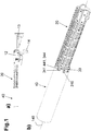
- FIG. 1a shows an overview of a weapon equipped according to the invention in a side view, with a casing ("handguard assembly") 20, a housing ("receiver") 12, a shaft ("stock”) 13, a handle (“grip”) 10 and a handle according to the invention
- the selected example of the illustration of the accessory 40 is based on a shielding of a silencer and is deliberately shown in a very simplified manner.
- the transfer of the inventive coupling of an accessory 40, such as lamps, visors, or other accessories, can be carried out mutatis mutandis by the person skilled in the art in the light of the disclosure.
- the accessory 40 is shown as a simple cylinder without any further design features; the necessary details are only given in the area of assembly. This is due to the fact that, apart from these features relevant to the fastening, the design of the accessory 40 is not essential for the invention.
- FIG. 1b a schematic oblique view of an adapted accessory 40 on the casing 20 is shown.
- the coupling of the accessory part by means of a sliding and rotating connection in the manner of a "bayonet lock” can be seen, which is formed by bayonet extensions 341 and correspondingly shaped bayonet grooves 441 of the accessory part 40.
- FIG. 1b A preferred embodiment is indicated, in which a spring-preloaded push button 310 engages in corresponding holes 425 in the radial direction outward to secure against unintentional rotation of the accessory 40.
- the accessory 40 has several L-shaped bayonet recesses 430 which extend from the edge of the accessory 40 facing the weapon.
- the bayonet recesses 430 can in principle also have an arcuate design. This embodiment is not shown, whereby the person skilled in the art can easily understand that a bracing in the direction of the adapter 30 can be carried out by means of an arcuate design due to the twisting movement of the accessory part 40.
- the at least one bayonet groove 430 has an L-shape with a first leg, which extends from the edge of the weapon-side end parallel to the barrel axis 140, and a second leg, which is then formed to run in the circumferential direction.
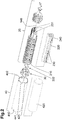
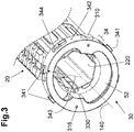
- FIG. 3 is an exploded view of the FIG Figure 1b components shown. In principle, these can also be designed in one piece on the handguard 20 to form the fore-end, the Fig. 2 provides an example of several components forming the casing 20.
- FIG Fig. 2 a heat shield (“heat shield”) 220 is shown, which is intended for inclusion within the handguard 210.
- heat shield guide extensions 230 can be seen, which are used for guidance or storage in the handguard 210.
- several guides 231 can be seen on the inside of the handguard 210.
- the heat shield 220 can be inserted along these guides 231 and is guided by means of the guide extensions 230 and held at a defined distance from the barrel 10 or from the handguard 210, as shown in a synopsis Figs. 3 and 5 becomes particularly clear and is explained in more detail below.
- These guides 231 can be designed as grooves or also as functionally identical protruding double strips for the guide extensions 230 to form a corresponding system and guide.
- Fig. 2 a plurality of screws 332 are shown, which are used to fasten the adapter 30 in the area of the rear section 32 on the handguard 210.
- the handguard 210 has a "right-hand thread" when viewed from the outside, and the screws 332 are designed as a type of countersunk head screws with a tool holder, e.g. hexagon socket or Torx, in the shaft.
- a tool holder e.g. hexagon socket or Torx
- the screws 332 can be screwed from the inside of the adapter 30 in the radial direction in the area of the rear section 32 to the outside on the handguard 210 by moving a screwdriver from the outside to the "left” and thus the adapter 30 in the area of its support surface 333 Pulls "outside” on the handguard 210.
- This “wrong screw” method offers the advantage that no screw heads are on the outside and the outer contour of the handguard 210 remains unaffected. In addition, this is a relatively loss-proof attachment of the screws.
- the adapter 30 preferably has a generally annular or generally tubular construction, depending on the point of view.
- the front section 34 is designed to be essentially ring-shaped for attaching the accessories 40, while the rear section 32 is modeled in its shape on the inner contour of the handguard 210 to be contacted, as seen in conjunction with Fig. 4 becomes clear.
- the formation of projections protruding from the front section 34 on the weapon side would be sufficient to ensure a good connection to the handguard 210.
- the Fig. 4 shows that the rear section 32 has smaller dimensions in the radial direction 323 starting from the running axis 140 to the bearing surfaces 333 which, in the assembled state, lie flat against complementary inner surfaces of the handguard 210.
- the radial dimensions 323, 343 can also be approximately the same, or in special cases even the rear radial distance 323 to the support surface 333 be less than the front radial distance 343 to the coupling surface 342 make optimal coordination of the dimensions with knowledge of the present invention.
- the preferred, stepped design of the adapter 30 is shown, the distance in the radial direction 343 from the coupling surface 342 being greater in the front section 34 than in the rear section 32.
- This has the great advantage that a sighting device, optical / thermal aiming devices and the like do not protrude beyond the sighting line of the upper edge of the weapon.
- Another advantage of the stepped design of the adapter 30 is that when the adapter 30 is mounted on the handguard 210, the in Fig. 4 clearly visible lateral dowel pin holes 316 are covered and thus undesired loosening during use can be avoided.
- the coupling surface 342 has the form of sections of lateral surfaces of at least one circular cylinder with the running axis 140 as the center of the circle and, when the accessory 40 is mounted, is in flat contact with at least one inner surface of the accessory 40 designed as a counter-coupling surface 442.
- Flat contact or flat contact are to be seen and understood technically and not mathematically.
- the accessory 40 and the adapter 30 have in the area of the coupling or counter-coupling surfaces 342, 442 a bayonet lock known per se, such as in particular the Fig. 2 shows well. In this way, the accessory 40 can simply be plugged onto the adapter 30 and rotated without the muzzle attachment 111 ( Figure 5a ), in the illustrated embodiment a muffler, touches this. It is of course possible to provide supports if so desired.
- several adapter openings 344 are formed on the front section 34 of the adapter 30, which are arranged in the running direction 140 and / or circumferential direction such that when the accessory 40 is coupled - i.e.
- the arrangement of at least two adapter openings 344 which are each formed at an angle of at least 15 ° to an imaginary upward in the vertical direction, is also particularly preferred.
- a plurality of adapter openings 344 can also be formed over the circumference, in particular on the underside for better air supply, but the upper area - when the firearm is held horizontally - should not be penetrated by an adapter opening 344.
- This arrangement of the adapter openings 344 is suitable for minimizing the so-called “mirage effect”, that is to say the turbulence of air that has become hot, which can be disadvantageous when looking through a sighting device.
- the assembly is preferably fixed, as shown, by means of at least one, preferably two, spring-loaded push buttons 310. These are biased outward in the radial direction by means of at least one spring 311 and can snap into locking holes 425 in the accessory 40 when the bayonet lock is engaged and twisted the bayonet extensions 341 is locked in the bayonet grooves 441.
- the lock is released by manually pressing the pushbuttons 310 and the accessory 40 can be easily removed by twisting and pulling off the casing 20 or the adapter 30.
- two springs 311 located in spring bores can also be provided per push button 310, between which (in the assembled state) a slot 312 is arranged parallel to the barrel axis.
- This slot is elongated in the radial direction (with respect to the barrel axis), and a pin, preferably a dowel pin 315, protrudes into it, through which the radial Mobility of the push button 310 is limited on both sides. In this way, the radial deflection of the push button 310 can take place within limits and the accessory 40 can be dismantled / assembled without tools.
- the attachment of the adapter 30 to the casing 20 takes place according to the specification by the existing casing, but in any case preferably in the engagement area of the support surface (s) 333 by means of screws 332. These penetrate the screw holes 331, as before with reference to the description of FIG Fig. 2 explained, and together with the support surfaces 333 produce a mechanically reliable connection of the two components.
- Guides 330 are provided for an optionally usable heat shield 220, this is explained further above.
- a silencer cover (“suppressor cover”) is shown as an accessory 40, this has a cover (“cover”) 410 which has a stop 421 at its front end.
- an optionally provided filling 420 which can be, for example, an insulating mat made of glass fiber or the like, is stretched against the adapter 30.
- an (air) gap 50 remains between the shell 410 or the filling 420, which allows a “draft” of air past the muffler.
- Figs. 6a, b show a cross section normal to the barrel axis 140 through the adapter 30 once, Figure 6a , in the fixed position of the accessory 40 and once, Figure 6b , after putting on, but before twisting or locking the bayonet catch 341, 441.
- a particularly effective solution to the heat dissipation problem for the barrel 10 is "eliminated” in one embodiment of the invention by means of a corresponding shape of the adapter 30.
- Fig. 3 the view from obliquely onto the adapter 30 attached to the casing 20 is shown.
- a heat shield 220 (“heatshield”) is arranged, which in Fig. 2 is shown in the ready-to-insert state.
- this heat shield 220 has only a few intended contact points or lines in the form of guide extensions 230 which touch the casing 210 on its inside in guides 231 provided for this purpose.
- the adapter 30 has the already mentioned separate heat shield guides 330 ( Fig. 3 , Fig. 4 ), which, if necessary, accommodate the front (st) guide extensions 230.
- the heat shield 220 is also aligned and positioned in all directions (running direction, axial direction) so that the barrel 1 is not touched, and that at Movement of the weapon, a rattling of the heat shield 220 in the casing 210 is reliably prevented.
- the invention is not limited to the illustrated and described exemplary embodiment, but can be adapted and configured in various ways.
- it relates not only to an accessory 40 designed according to the invention, but also to the adapter 30 per se and also to a weapon provided with such an adapter.
- the weapon-side part of the adapter 30 can be part of the handguard 210, so that it integrally forms the part of the adapter 30 provided with a larger radius, including the bayonet lock, at its front end.
- the adapter 30 can be dispensed with as a separate component, more precisely the rear section 32 is dispensed with, and the front section 34 of the adapter 30 is formed integrally on the handguard 210.
- both the mechanical stability of the connection of an accessory to the weapon, the precision of the weapon, as well as the heat dissipation at the barrel and / or a muzzle attachment can be improved in the manner according to the invention, and a reduction in the thermal signature can still be achieved.
Landscapes
- Engineering & Computer Science (AREA)
- General Engineering & Computer Science (AREA)
- Aiming, Guidance, Guns With A Light Source, Armor, Camouflage, And Targets (AREA)
- Clamps And Clips (AREA)
- Gripping Jigs, Holding Jigs, And Positioning Jigs (AREA)
Priority Applications (8)
| Application Number | Priority Date | Filing Date | Title |
|---|---|---|---|
| EP19215974.7A EP3835706B1 (fr) | 2019-12-13 | 2019-12-13 | Adaptateur destiné au montage d'une pièce accessoire sur une arme à feu |
| EP19216891.2A EP3835708B1 (fr) | 2019-12-13 | 2019-12-17 | Garde-main destiné au montage par serrage sur une arme à feu existante |
| PCT/EP2020/083075 WO2021121877A1 (fr) | 2019-12-13 | 2020-11-23 | Garde-main destiné à être monté par serrage sur une arme à feu existante |
| BR112022011131A BR112022011131A2 (pt) | 2019-12-13 | 2020-11-23 | Protetor de mão para fixação da montagem de uma arma de fogo existente |
| CA3163898A CA3163898A1 (fr) | 2019-12-13 | 2020-11-23 | Garde-main destine a etre monte par serrage sur une arme a feu existante |
| IL293577A IL293577A (en) | 2019-12-13 | 2020-11-23 | A hand guard for fastening mounting on an existing firearm |
| US17/757,291 US11892260B2 (en) | 2019-12-13 | 2020-11-23 | Handguard for clamping mounting on an existing firearm |
| US17/120,695 US11391532B2 (en) | 2019-12-13 | 2020-12-14 | Adapter for mounting an accessory on a firearm |
Applications Claiming Priority (1)
| Application Number | Priority Date | Filing Date | Title |
|---|---|---|---|
| EP19215974.7A EP3835706B1 (fr) | 2019-12-13 | 2019-12-13 | Adaptateur destiné au montage d'une pièce accessoire sur une arme à feu |
Publications (3)
| Publication Number | Publication Date |
|---|---|
| EP3835706A1 true EP3835706A1 (fr) | 2021-06-16 |
| EP3835706B1 EP3835706B1 (fr) | 2023-10-18 |
| EP3835706C0 EP3835706C0 (fr) | 2023-10-18 |
Family
ID=68916369
Family Applications (2)
| Application Number | Title | Priority Date | Filing Date |
|---|---|---|---|
| EP19215974.7A Active EP3835706B1 (fr) | 2019-12-13 | 2019-12-13 | Adaptateur destiné au montage d'une pièce accessoire sur une arme à feu |
| EP19216891.2A Active EP3835708B1 (fr) | 2019-12-13 | 2019-12-17 | Garde-main destiné au montage par serrage sur une arme à feu existante |
Family Applications After (1)
| Application Number | Title | Priority Date | Filing Date |
|---|---|---|---|
| EP19216891.2A Active EP3835708B1 (fr) | 2019-12-13 | 2019-12-17 | Garde-main destiné au montage par serrage sur une arme à feu existante |
Country Status (6)
| Country | Link |
|---|---|
| US (2) | US11892260B2 (fr) |
| EP (2) | EP3835706B1 (fr) |
| BR (1) | BR112022011131A2 (fr) |
| CA (1) | CA3163898A1 (fr) |
| IL (1) | IL293577A (fr) |
| WO (1) | WO2021121877A1 (fr) |
Families Citing this family (8)
| Publication number | Priority date | Publication date | Assignee | Title |
|---|---|---|---|---|
| USD1015475S1 (en) * | 2019-12-05 | 2024-02-20 | Glock Technology Gmbh | Firearm upper receiver |
| USD1023214S1 (en) * | 2020-06-23 | 2024-04-16 | Bravo Company Mfg, Inc. | Firearm upper receiver |
| US20220196364A1 (en) * | 2020-12-17 | 2022-06-23 | James Matthew Underwood | Handguard |
| US20220252374A1 (en) * | 2021-02-11 | 2022-08-11 | Jason Louthan | Modular handguard for firearm |
| US20220282951A1 (en) * | 2021-03-04 | 2022-09-08 | Bowden Tactical, LLC | Interchangeable handguard system |
| USD1027094S1 (en) * | 2021-04-15 | 2024-05-14 | Angstadt Arms, LLC | Firearm upper assembly |
| US11725904B2 (en) * | 2021-11-23 | 2023-08-15 | Strike IP, LLC | Firearm handguard with bridge adapter |
| EP4194795A1 (fr) | 2021-12-10 | 2023-06-14 | Glock Technology GmbH | Dispositif de réalisation d'une fixation secondaire d'un garde-main |
Citations (4)
| Publication number | Priority date | Publication date | Assignee | Title |
|---|---|---|---|---|
| WO2009139803A2 (fr) * | 2008-02-21 | 2009-11-19 | George Koumbis | Assemblage et silencieux pour armes à feu |
| US20130133976A1 (en) * | 2011-11-29 | 2013-05-30 | A-Tec Holding As | Silencer for a firearm |
| US9658010B1 (en) * | 2014-10-13 | 2017-05-23 | Paul Oglesby | Heat shielding and thermal venting system |
| US20190072354A1 (en) * | 2017-04-27 | 2019-03-07 | Darryl S. Lee | Firearm Suppressor Adapter for Firearm Rails |
Family Cites Families (30)
| Publication number | Priority date | Publication date | Assignee | Title |
|---|---|---|---|---|
| US968583A (en) * | 1909-08-12 | 1910-08-30 | Onesime E Michaud | Attachment for shotguns. |
| US985308A (en) * | 1911-01-09 | 1911-02-28 | Jesse Owen Van Voorhis | Firearm. |
| US2880435A (en) * | 1955-01-18 | 1959-04-07 | Herman T Hale | Pipe cleaning apparatus |
| US4887929A (en) * | 1988-04-25 | 1989-12-19 | Electric Eel Manufacturing Co., Inc. | Cable coupler |
| US4920679A (en) * | 1988-09-21 | 1990-05-01 | Sarles J Stephen | Firearm with detachable barrel |
| US4893426A (en) * | 1988-10-07 | 1990-01-16 | South Central Research Corp. | Lugged coupling apparatus |
| US5271312A (en) * | 1990-12-14 | 1993-12-21 | Colt's Manufacturing Company Inc. | Locating spring and plunger assembly for a firearm |
| US5433133A (en) * | 1994-03-07 | 1995-07-18 | La France; Timothy F. | Quick detachable gun barrel coupling member |
| US5559302A (en) * | 1995-08-31 | 1996-09-24 | Gsl Technology, Inc. | Bayonet type coupling for firearms |
| US6873185B2 (en) | 2002-06-19 | 2005-03-29 | Viasic, Inc. | Logic array devices having complex macro-cell architecture and methods facilitating use of same |
| KR100686794B1 (ko) | 2005-01-25 | 2007-02-23 | 삼성에스디아이 주식회사 | 배터리팩의 모니터링 장치 및 그 방법 |
| US7523580B1 (en) * | 2005-11-07 | 2009-04-28 | Jerome Benedict Tankersley | Handguard system integrated to a firearm |
| US7516690B2 (en) * | 2006-12-22 | 2009-04-14 | Mcclellan W Thomas | Firearm suppressor, mounting system and mounting method |
| US9021673B2 (en) * | 2011-02-26 | 2015-05-05 | Steven Ray | Snake glove |
| CZ303454B6 (cs) * | 2011-07-21 | 2012-09-19 | Proarms Armory S. R. O. | Usporádání k výmene a zajištení hlavne dlouhé strelné zbrane |
| US8819980B2 (en) | 2012-11-12 | 2014-09-02 | WHG Properties, LLC | Modular rifle handguard |
| US9175919B2 (en) * | 2013-08-16 | 2015-11-03 | Travis Russell | System and method for attaching a sound suppressor to a firearm |
| US8931196B1 (en) * | 2013-11-18 | 2015-01-13 | Mark C. LaRue | Firearm having capability for field assembly and disassembly |
| US20150377584A1 (en) * | 2014-06-25 | 2015-12-31 | Ati Ip, Llc | Forend-mounted heatshield arrangement for firearms |
| US10107582B2 (en) * | 2015-12-04 | 2018-10-23 | Scott Gray | Quick connect rifle receiver adapter system |
| US9513078B1 (en) * | 2016-05-17 | 2016-12-06 | Precision Tooling Products, LLC | Quick mount firearm barrel accessory |
| US10641573B2 (en) * | 2017-02-27 | 2020-05-05 | Strike Industries, Inc. | Lock mechanism for muzzle shroud and blast diffuser using the same |
| US11047640B1 (en) * | 2017-11-21 | 2021-06-29 | Stwip Llc | Device for dampening residual effects from a firearm suppressor |
| US10480897B2 (en) * | 2017-11-29 | 2019-11-19 | Occam Defense Solutions Inc. | Handguard system for firearms |
| US10352650B2 (en) * | 2017-12-01 | 2019-07-16 | Spec Arms LLC | Firearm handguard securement system and related method |
| US10801798B2 (en) * | 2017-12-29 | 2020-10-13 | Super Dave Designs, LLC | Barrel mounting system |
| US11187474B2 (en) * | 2018-01-09 | 2021-11-30 | William E. Masters | Compact shotgun, multipurpose mount, and trigger assembly |
| US10436549B1 (en) * | 2018-10-02 | 2019-10-08 | 5th Axis, Inc. | Rifle handguard system |
| US10775129B1 (en) * | 2019-09-20 | 2020-09-15 | Bravo Company Mfg, Inc. | Handguard mount with tie bar |
| US11408702B2 (en) * | 2020-06-16 | 2022-08-09 | Austin Reis-Green | Firearm muzzle accessory coupling device, system and method |
-
2019
- 2019-12-13 EP EP19215974.7A patent/EP3835706B1/fr active Active
- 2019-12-17 EP EP19216891.2A patent/EP3835708B1/fr active Active
-
2020
- 2020-11-23 IL IL293577A patent/IL293577A/en unknown
- 2020-11-23 CA CA3163898A patent/CA3163898A1/fr active Pending
- 2020-11-23 WO PCT/EP2020/083075 patent/WO2021121877A1/fr active Application Filing
- 2020-11-23 US US17/757,291 patent/US11892260B2/en active Active
- 2020-11-23 BR BR112022011131A patent/BR112022011131A2/pt unknown
- 2020-12-14 US US17/120,695 patent/US11391532B2/en active Active
Patent Citations (4)
| Publication number | Priority date | Publication date | Assignee | Title |
|---|---|---|---|---|
| WO2009139803A2 (fr) * | 2008-02-21 | 2009-11-19 | George Koumbis | Assemblage et silencieux pour armes à feu |
| US20130133976A1 (en) * | 2011-11-29 | 2013-05-30 | A-Tec Holding As | Silencer for a firearm |
| US9658010B1 (en) * | 2014-10-13 | 2017-05-23 | Paul Oglesby | Heat shielding and thermal venting system |
| US20190072354A1 (en) * | 2017-04-27 | 2019-03-07 | Darryl S. Lee | Firearm Suppressor Adapter for Firearm Rails |
Also Published As
| Publication number | Publication date |
|---|---|
| EP3835708B1 (fr) | 2023-12-06 |
| EP3835706B1 (fr) | 2023-10-18 |
| US20210180903A1 (en) | 2021-06-17 |
| BR112022011131A2 (pt) | 2022-08-23 |
| EP3835708C0 (fr) | 2023-12-06 |
| US20230020437A1 (en) | 2023-01-19 |
| IL293577A (en) | 2022-08-01 |
| CA3163898A1 (fr) | 2021-06-24 |
| US11892260B2 (en) | 2024-02-06 |
| EP3835706C0 (fr) | 2023-10-18 |
| US11391532B2 (en) | 2022-07-19 |
| WO2021121877A1 (fr) | 2021-06-24 |
| EP3835708A1 (fr) | 2021-06-16 |
Similar Documents
| Publication | Publication Date | Title |
|---|---|---|
| EP3835706B1 (fr) | Adaptateur destiné au montage d'une pièce accessoire sur une arme à feu | |
| EP1924815B1 (fr) | Bloc cylindrique pour la recuperation de gaz et arme de poing | |
| DE102011013575B4 (de) | Vorrichtung zum Befestigen eines Zusatzgerätes an einer Schusswaffe | |
| EP2339287B1 (fr) | Système de serrage pour des accessoires sur un rail Picatinny | |
| DE3522027C2 (fr) | ||
| EP1147360B1 (fr) | Dispositif de levier de chargement pour une arme de poing | |
| DE102007063610A1 (de) | Visierelement | |
| DE102004006364A1 (de) | Schusswaffe, insbesondere selbstladendes Kleinkalibergewehr | |
| EP1975541A2 (fr) | Crosse d'une arme à répétition et boîte de culasse d'une telle arme à répétition pour une telle crosse | |
| DE2402445A1 (de) | Vorrichtung zum verschwenkbaren seitlichen auswerfen fuer waffen | |
| EP4038337B1 (fr) | Unité canon pour arme à feu | |
| DE202011102875U1 (de) | Aufkippmontage mit zusätzlichem Anschlag | |
| WO2008014986A1 (fr) | Dispositif à charnière pour une arme, dispositif de visée et arme | |
| DE102015013803A1 (de) | Adapter zur Anbringung wenigstens einer Zusatzeinrichtung an einer Selbstlade-Feuerwaffe und mit diesem ausgestattete Selbstlade-Feuerwaffe | |
| EP1864073B1 (fr) | Systeme de serrage pour fixer un composant sur une arme a feu de poing et arme a feu de poing equipee de ce systeme | |
| EP3892954B1 (fr) | Dispositif de fixation pour accessoire d'arme | |
| EP3835705A1 (fr) | Arrêtoir de culasse pour une arme à feu | |
| EP2660553A2 (fr) | Dispositif de montage pour la fixation amovible d'un dispositif de visée sur une arme à feu manuelle | |
| DE102005037884B3 (de) | Adapterbauteil | |
| AT398841B (de) | Vorrichtung zur lösbaren montage einer granatwerfereinrichtung an einem automatischen gewehr | |
| DE2426571A1 (de) | Visiereinrichtungen fuer schusswaffen | |
| EP4038332B1 (fr) | Culasse pour une arme à feu | |
| DE102007005142B4 (de) | Anschlussstück | |
| DE102020126023A1 (de) | Schalldämpfer | |
| DE102016113983A1 (de) | Schalldämpfer |
Legal Events
| Date | Code | Title | Description |
|---|---|---|---|
| PUAI | Public reference made under article 153(3) epc to a published international application that has entered the european phase |
Free format text: ORIGINAL CODE: 0009012 |
|
| STAA | Information on the status of an ep patent application or granted ep patent |
Free format text: STATUS: REQUEST FOR EXAMINATION WAS MADE |
|
| 17P | Request for examination filed |
Effective date: 20210330 |
|
| AK | Designated contracting states |
Kind code of ref document: A1 Designated state(s): AL AT BE BG CH CY CZ DE DK EE ES FI FR GB GR HR HU IE IS IT LI LT LU LV MC MK MT NL NO PL PT RO RS SE SI SK SM TR |
|
| STAA | Information on the status of an ep patent application or granted ep patent |
Free format text: STATUS: EXAMINATION IS IN PROGRESS |
|
| 17Q | First examination report despatched |
Effective date: 20230221 |
|
| GRAP | Despatch of communication of intention to grant a patent |
Free format text: ORIGINAL CODE: EPIDOSNIGR1 |
|
| STAA | Information on the status of an ep patent application or granted ep patent |
Free format text: STATUS: GRANT OF PATENT IS INTENDED |
|
| INTG | Intention to grant announced |
Effective date: 20230809 |
|
| GRAS | Grant fee paid |
Free format text: ORIGINAL CODE: EPIDOSNIGR3 |
|
| GRAA | (expected) grant |
Free format text: ORIGINAL CODE: 0009210 |
|
| STAA | Information on the status of an ep patent application or granted ep patent |
Free format text: STATUS: THE PATENT HAS BEEN GRANTED |
|
| AK | Designated contracting states |
Kind code of ref document: B1 Designated state(s): AL AT BE BG CH CY CZ DE DK EE ES FI FR GB GR HR HU IE IS IT LI LT LU LV MC MK MT NL NO PL PT RO RS SE SI SK SM TR |
|
| REG | Reference to a national code |
Ref country code: GB Ref legal event code: FG4D Free format text: NOT ENGLISH |
|
| REG | Reference to a national code |
Ref country code: CH Ref legal event code: EP |
|
| REG | Reference to a national code |
Ref country code: IE Ref legal event code: FG4D Free format text: LANGUAGE OF EP DOCUMENT: GERMAN |
|
| REG | Reference to a national code |
Ref country code: DE Ref legal event code: R096 Ref document number: 502019009690 Country of ref document: DE |
|
| U01 | Request for unitary effect filed |
Effective date: 20231030 |
|
| U07 | Unitary effect registered |
Designated state(s): AT BE BG DE DK EE FI FR IT LT LU LV MT NL PT SE SI Effective date: 20231106 |
|
| U20 | Renewal fee paid [unitary effect] |
Year of fee payment: 5 Effective date: 20231130 |
|
| PGFP | Annual fee paid to national office [announced via postgrant information from national office to epo] |
Ref country code: GB Payment date: 20231204 Year of fee payment: 5 |
|
| PGFP | Annual fee paid to national office [announced via postgrant information from national office to epo] |
Ref country code: CZ Payment date: 20231204 Year of fee payment: 5 |
|
| PG25 | Lapsed in a contracting state [announced via postgrant information from national office to epo] |
Ref country code: GR Free format text: LAPSE BECAUSE OF FAILURE TO SUBMIT A TRANSLATION OF THE DESCRIPTION OR TO PAY THE FEE WITHIN THE PRESCRIBED TIME-LIMIT Effective date: 20240119 |
|
| PG25 | Lapsed in a contracting state [announced via postgrant information from national office to epo] |
Ref country code: IS Free format text: LAPSE BECAUSE OF FAILURE TO SUBMIT A TRANSLATION OF THE DESCRIPTION OR TO PAY THE FEE WITHIN THE PRESCRIBED TIME-LIMIT Effective date: 20240218 |
|
| PG25 | Lapsed in a contracting state [announced via postgrant information from national office to epo] |
Ref country code: ES Free format text: LAPSE BECAUSE OF FAILURE TO SUBMIT A TRANSLATION OF THE DESCRIPTION OR TO PAY THE FEE WITHIN THE PRESCRIBED TIME-LIMIT Effective date: 20231018 |
|
| PG25 | Lapsed in a contracting state [announced via postgrant information from national office to epo] |
Ref country code: IS Free format text: LAPSE BECAUSE OF FAILURE TO SUBMIT A TRANSLATION OF THE DESCRIPTION OR TO PAY THE FEE WITHIN THE PRESCRIBED TIME-LIMIT Effective date: 20240218 Ref country code: GR Free format text: LAPSE BECAUSE OF FAILURE TO SUBMIT A TRANSLATION OF THE DESCRIPTION OR TO PAY THE FEE WITHIN THE PRESCRIBED TIME-LIMIT Effective date: 20240119 Ref country code: ES Free format text: LAPSE BECAUSE OF FAILURE TO SUBMIT A TRANSLATION OF THE DESCRIPTION OR TO PAY THE FEE WITHIN THE PRESCRIBED TIME-LIMIT Effective date: 20231018 |