EP3835708B1 - Garde-main destiné au montage par serrage sur une arme à feu existante - Google Patents
Garde-main destiné au montage par serrage sur une arme à feu existante Download PDFInfo
- Publication number
- EP3835708B1 EP3835708B1 EP19216891.2A EP19216891A EP3835708B1 EP 3835708 B1 EP3835708 B1 EP 3835708B1 EP 19216891 A EP19216891 A EP 19216891A EP 3835708 B1 EP3835708 B1 EP 3835708B1
- Authority
- EP
- European Patent Office
- Prior art keywords
- nut
- axis
- lever
- barrel
- clamping
- Prior art date
- Legal status (The legal status is an assumption and is not a legal conclusion. Google has not performed a legal analysis and makes no representation as to the accuracy of the status listed.)
- Active
Links
- 238000006073 displacement reaction Methods 0.000 description 5
- 239000007789 gas Substances 0.000 description 4
- 238000013461 design Methods 0.000 description 3
- 125000006850 spacer group Chemical group 0.000 description 3
- 230000009471 action Effects 0.000 description 1
- 238000013459 approach Methods 0.000 description 1
- 238000002474 experimental method Methods 0.000 description 1
- 238000004880 explosion Methods 0.000 description 1
- 210000000245 forearm Anatomy 0.000 description 1
- 238000009434 installation Methods 0.000 description 1
- 238000012423 maintenance Methods 0.000 description 1
- 238000004519 manufacturing process Methods 0.000 description 1
- 239000000463 material Substances 0.000 description 1
- 238000000034 method Methods 0.000 description 1
- 238000012986 modification Methods 0.000 description 1
- 230000004048 modification Effects 0.000 description 1
- 230000008569 process Effects 0.000 description 1
- 238000012545 processing Methods 0.000 description 1
- 239000002904 solvent Substances 0.000 description 1
- 238000012546 transfer Methods 0.000 description 1
Images


Classifications
-
- F—MECHANICAL ENGINEERING; LIGHTING; HEATING; WEAPONS; BLASTING
- F41—WEAPONS
- F41A—FUNCTIONAL FEATURES OR DETAILS COMMON TO BOTH SMALLARMS AND ORDNANCE, e.g. CANNONS; MOUNTINGS FOR SMALLARMS OR ORDNANCE
- F41A21/00—Barrels; Gun tubes; Muzzle attachments; Barrel mounting means
- F41A21/32—Muzzle attachments or glands
- F41A21/325—Mountings for muzzle attachments
-
- F—MECHANICAL ENGINEERING; LIGHTING; HEATING; WEAPONS; BLASTING
- F41—WEAPONS
- F41C—SMALLARMS, e.g. PISTOLS, RIFLES; ACCESSORIES THEREFOR
- F41C23/00—Butts; Butt plates; Stocks
- F41C23/16—Forestocks; Handgrips; Hand guards
-
- F—MECHANICAL ENGINEERING; LIGHTING; HEATING; WEAPONS; BLASTING
- F41—WEAPONS
- F41A—FUNCTIONAL FEATURES OR DETAILS COMMON TO BOTH SMALLARMS AND ORDNANCE, e.g. CANNONS; MOUNTINGS FOR SMALLARMS OR ORDNANCE
- F41A21/00—Barrels; Gun tubes; Muzzle attachments; Barrel mounting means
- F41A21/30—Silencers
-
- F—MECHANICAL ENGINEERING; LIGHTING; HEATING; WEAPONS; BLASTING
- F41—WEAPONS
- F41A—FUNCTIONAL FEATURES OR DETAILS COMMON TO BOTH SMALLARMS AND ORDNANCE, e.g. CANNONS; MOUNTINGS FOR SMALLARMS OR ORDNANCE
- F41A21/00—Barrels; Gun tubes; Muzzle attachments; Barrel mounting means
- F41A21/44—Insulation jackets; Protective jackets
-
- F—MECHANICAL ENGINEERING; LIGHTING; HEATING; WEAPONS; BLASTING
- F41—WEAPONS
- F41A—FUNCTIONAL FEATURES OR DETAILS COMMON TO BOTH SMALLARMS AND ORDNANCE, e.g. CANNONS; MOUNTINGS FOR SMALLARMS OR ORDNANCE
- F41A21/00—Barrels; Gun tubes; Muzzle attachments; Barrel mounting means
- F41A21/48—Barrel mounting means, e.g. releasable mountings for replaceable barrels
- F41A21/481—Barrel mounting means, e.g. releasable mountings for replaceable barrels using partial or interrupted threads, e.g. bayonet-type mountings
-
- F—MECHANICAL ENGINEERING; LIGHTING; HEATING; WEAPONS; BLASTING
- F41—WEAPONS
- F41A—FUNCTIONAL FEATURES OR DETAILS COMMON TO BOTH SMALLARMS AND ORDNANCE, e.g. CANNONS; MOUNTINGS FOR SMALLARMS OR ORDNANCE
- F41A21/00—Barrels; Gun tubes; Muzzle attachments; Barrel mounting means
- F41A21/48—Barrel mounting means, e.g. releasable mountings for replaceable barrels
- F41A21/484—Barrel mounting means, e.g. releasable mountings for replaceable barrels using interlocking means, e.g. by sliding pins
-
- F—MECHANICAL ENGINEERING; LIGHTING; HEATING; WEAPONS; BLASTING
- F41—WEAPONS
- F41A—FUNCTIONAL FEATURES OR DETAILS COMMON TO BOTH SMALLARMS AND ORDNANCE, e.g. CANNONS; MOUNTINGS FOR SMALLARMS OR ORDNANCE
- F41A21/00—Barrels; Gun tubes; Muzzle attachments; Barrel mounting means
- F41A21/48—Barrel mounting means, e.g. releasable mountings for replaceable barrels
- F41A21/485—Barrel mounting means, e.g. releasable mountings for replaceable barrels using screws or bolts
Definitions
- the invention relates to a fore-end for clamping mounting on a firearm, in particular a rifle (carbine), also referred to in simple terms as fore-end clamping or just clamping, especially for weapons of the M4/M16/AR15 rifle type, according to the preamble of claim 1 and the WO 2013/010516 A1 .
- the clamping device according to the invention and its variants are not limited to rifles, carbines, etc., but can in principle also be used for pistols. The improvements and their effects/benefits are listed below.
- the forend can be understood as a kind of extension of the housing of a rifle in the direction of the barrel.
- the forend In order to improve the precision of a rifle, the forend must be connected to the housing as rigidly as possible relative to the barrel and therefore also relative to the housing. However, the barrel must be able to swing “freely” when the shot is fired.
- the barrel is usually attached to the housing using a barrel nut, which is usually designed as a union nut and is screwed to the housing.
- the barrel nut presses the barrel against a radially projecting shoulder of the housing.
- a plurality of components are required to form a clamping at least in the tangential direction. Securing and pre-tensioning the barrel in the axial direction, preferably also via a clamp, would also be desirable in order to form the most rigid connection possible between the housing and forend.
- the object of the present invention is therefore to provide a clamping device which secures the forend against displacement relative to the housing and at the same time ensures a rigid connection to the housing.
- a further object of the invention is that the smallest possible number of components is used for the clamping device.
- a further object of the invention is to provide a clamping device that is easy to handle, easy to maintain and has a relatively simple structure.
- FIGs. 1-6 Examples of embodiments are shown that are suitable for use in an AR15 or M4 rifle. Modifications of the examples shown can be easily and simply transferred to other types of rifles by a person skilled in the art with knowledge of the invention and without extensive or complex experiments.
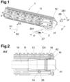
- the Fig. 1 shows a schematic exploded view of a forend 1 with housing 11 and built-in spacer 12, which is not essential to the invention and is therefore not explained further. Also shown is a clamping device 2 according to the invention with a lever 21, a nut 28 and a locking ring 281; a coordinate system used variously in the description and the claims 51-running direction, shaft direction, forward; 52-transverse direction to the left and 53-vertical direction upwards are entered for better orientation.
- the Fig. 2 shows section II-II of the Fig. 1 , an axial section through the shaft axis 41, thus parallel to the barrel axis.
- the barrel 15 is radially closest to the barrel axis (parallel or coinciding with the shaft axis 41), a barrel nut 13 in the form of an elongated sleeve is optionally pushed onto it and connected to the upper housing 14 at its rear end by means of a screw connection 42.
- This means that a collar of the barrel 15 is pressed by a rear end face of the barrel nut 13 against a front end face of the upper housing 14 and the barrel 15 itself is held in place.
- the housing 11 of the forend 1 not only encloses the barrel 15 including the barrel nut 13, but also a gas pipe 16.
- An annular groove 131 is provided in the running nut 13, the lever 21 lies partly in this annular groove and is cut in the area of its middle piece 26 in this illustration.
- the housing 11 there is an elongated hole running in the transverse direction 52 provided, the cross section of which has circular end sections two mutually parallel elongated hole axes 191, 192 running in the transverse direction 52. These axes lie in a plane normal to the vertical 52.
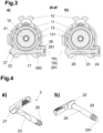
- the Figs. 3a ,b are a section along line III-III of the Fig. 1 , thus normal to the shaft axis 41, and represent two different clamping situations.
- the structure itself is as follows: The lever 21 is pushed with its threaded end first through the elongated hole 19, the nut 28 with its cone 282 is directed towards the weapon, screwed on and secured against loss by means of the resilient locking ring 281. By screwing on the nut 28, a longitudinal slot 17 in the housing 11 or the spacer 12 in the area of the lever 21 is changed in width and, together with the conical sections 22 of the shaft and 282 of the nut, ensures pretension and adjustment.
- the ones in the Figs. 4a ,b Clamping device 2 shown in detail consists of a lever 21 with a shaft with a lever axis 291, in one end region of which a thread 24 is provided, and at the other end of which a lever arm 27 projects approximately at a right angle.
- the diameter of the shaft increases conically towards the lever arm 27 and forms a clamping cone 22.
- the shaft has a recess 23 on the middle piece 26, approximately in the middle, which forms a generally cylindrical, preferably circular-cylindrical, lateral surface; in the exemplary embodiment, the generatrixes of the lateral surface run parallel to the plane defined by the lever axis and the lever arm 27.
- the thread 24 does not extend to the end of the shaft, but ends at an annular groove 25 whose inner diameter is smaller than the diameter of the thread base.
- the shaft diameter in the immediate end area is larger than that of the groove, but smaller than that of the thread base.
- a nut 28 interacts with the thread 24 of the shaft and is in the Figs. 5a -c is shown.
- This nut 28 is provided in a first axial region with an internal thread that can cooperate with the thread 24; in a second axial region it has a cylindrical bore (recess) with a larger diameter than the shaft diameter. This recess runs over the entire remaining length (actually height) of the nut 28.
- the outer contour of the nut is cylindrical with a subsequent conical taper towards the end, and in the second, an external hexagon is provided.
- FIG. 6a ,b An aspect of the invention that is also important in one embodiment lies in the design of the in the Figs. 6a ,b elongated hole 19 shown in more detail, which, as already mentioned, has two elongated hole axes 191, 192 running parallel to one another.
- the assembly is carried out with the lever 21 in the "OPEN” position until it stops on the "Upper”, then the nut 28 is tightened, narrowing the gap 17 and thus fixing the housing 5 to the running nut 128.
- This situation is essentially in Figs.7a -c shown.
- the first elongated hole axis 191 is further away from the upper housing 14 than the second elongated hole axis 192.
- Fig. 7a the housing 11 with the clamping device 2 is placed in the "OPEN" position, the lever axis 291 is at a distance from the second elongated hole axis 192 and is closer to the upper housing than this.
- the Fig. 7b shows the situation when turning the lever 21 into the "LOCKED" position, the two axes have become much closer to each other and can also coincide.
- Fig. 7c shows the situation after tightening the clamping nut 28, since the clamping surface 18, which is conical around the axis 191, as the arrow indicates, causes a load/displacement of the housing 11 of the forend 1 in the direction of the upper housing 14, thus stable mechanical conditions prevail .
- the invention thus enables tangential and axial clamping of the forend at the same time.
- the outer diameter of the nut 28 is selected such that a part of the weapon, preferably the slider (not shown), can be used to loosen the nut 28.
- the slider 28 with its slot-shaped opening, which allows the hammer or striker to pass through, can be used to screw on or unscrew the nut 28.
- a “half-inch” width of the nut head is therefore particularly preferred.
- substantially means a deviation of up to 10% of the specified value, if physically possible, both downwards and upwards, otherwise only in the sensible direction, for degrees (angle and temperature) This means ⁇ 10°.
Claims (2)
- Garde-main destiné au montage par serrage sur une arme à feu existante, en particulier sur le canon (15) de celle-ci ou sur l'écrou de canon (13) de celle-ci, le canon (15) ou l'écrou de canon (13) présentant une gorge annulaire (281), comprenant :- un boîtier de fût (11) qui est doté d'un axe de fût (41) et présente une fente (17) s'étendant radialement par rapport à ce dernier, et une ouverture de passage destinée à un dispositif de serrage et s'étendant dans la direction transversale (52),- un dispositif de serrage (2) pour le boîtier de fût (11), présentant∘ un levier (21) comprenant une pièce centrale (26) qui entoure l'axe de levier (291) et se situe dans un plan normal à l'axe de fût (41), dans l'ouverture de passage du boîtier de fût (11), et qui présente dans sa partie centrale un creux (23), un filetage (24) à une partie d'extrémité et un bras de levier (27) à l'autre extrémité, et∘ un écrou (28) comportant un filetage intérieur adapté au filetage (24) ;sachant que la pièce centrale (26), sur sa partie d'extrémité tournée vers le bras de levier (27), est dotée d'un cône de serrage (22) s'élargissant en direction du bras de levier (27), et est en contact avec une surface de serrage (18) conique du boîtier de fût (11) ;sachant qu'à l'état monté, l'écrou (28) est vissé sur le filetage (24) et rétrécit ainsi la fente (17), et que la position angulaire du levier (21) autour de son axe de levier (291) est telle que sa pièce centrale (26) soit en contact avec la gorge annulaire (281), caractérisé en ce que sur la face extérieure, l'écrou (28) est doté d'une portion conique, à savoir d'un cône de serrage (282), en ce que dans le boîtier de fût (11), l'ouverture de passage destinée à accueillir la pièce centrale (26) est un trou oblong (19) avec un contour formé de deux demi-cercles ayant un premier axe (191) et un deuxième axe (192) parallèle à celui-ci et un rectangle situé entre eux, et en ce que le trou oblong (19) présente aux deux extrémités des surfaces de serrage (18) coniques qui sont réalisées de façon centrée autour du premier axe (191) et qui coopèrent avec les cônes de serrage (22, 282).
- Garde-main selon la revendication 1, caractérisé en ce que la pièce centrale (26) est dotée d'une gorge annulaire (25) sur sa partie d'extrémité présentant le filetage (24), et en ce que l'écrou (28) présente le filetage intérieur dans une première portion axiale, en ce qu'un trou de plus grand diamètre est réalisé dans une deuxième portion axiale, et en ce qu'une bague de retenue (31) est insérée dans la gorge annulaire (25).
Priority Applications (5)
| Application Number | Priority Date | Filing Date | Title |
|---|---|---|---|
| IL293577A IL293577A (en) | 2019-12-13 | 2020-11-23 | A hand guard for fastening mounting on an existing firearm |
| PCT/EP2020/083075 WO2021121877A1 (fr) | 2019-12-13 | 2020-11-23 | Garde-main destiné à être monté par serrage sur une arme à feu existante |
| BR112022011131A BR112022011131A2 (pt) | 2019-12-13 | 2020-11-23 | Protetor de mão para fixação da montagem de uma arma de fogo existente |
| US17/757,291 US11892260B2 (en) | 2019-12-13 | 2020-11-23 | Handguard for clamping mounting on an existing firearm |
| CA3163898A CA3163898A1 (fr) | 2019-12-13 | 2020-11-23 | Garde-main destine a etre monte par serrage sur une arme a feu existante |
Applications Claiming Priority (1)
| Application Number | Priority Date | Filing Date | Title |
|---|---|---|---|
| EP19215974.7A EP3835706B1 (fr) | 2019-12-13 | 2019-12-13 | Adaptateur destiné au montage d'une pièce accessoire sur une arme à feu |
Publications (3)
| Publication Number | Publication Date |
|---|---|
| EP3835708A1 EP3835708A1 (fr) | 2021-06-16 |
| EP3835708C0 EP3835708C0 (fr) | 2023-12-06 |
| EP3835708B1 true EP3835708B1 (fr) | 2023-12-06 |
Family
ID=68916369
Family Applications (2)
| Application Number | Title | Priority Date | Filing Date |
|---|---|---|---|
| EP19215974.7A Active EP3835706B1 (fr) | 2019-12-13 | 2019-12-13 | Adaptateur destiné au montage d'une pièce accessoire sur une arme à feu |
| EP19216891.2A Active EP3835708B1 (fr) | 2019-12-13 | 2019-12-17 | Garde-main destiné au montage par serrage sur une arme à feu existante |
Family Applications Before (1)
| Application Number | Title | Priority Date | Filing Date |
|---|---|---|---|
| EP19215974.7A Active EP3835706B1 (fr) | 2019-12-13 | 2019-12-13 | Adaptateur destiné au montage d'une pièce accessoire sur une arme à feu |
Country Status (6)
| Country | Link |
|---|---|
| US (2) | US11892260B2 (fr) |
| EP (2) | EP3835706B1 (fr) |
| BR (1) | BR112022011131A2 (fr) |
| CA (1) | CA3163898A1 (fr) |
| IL (1) | IL293577A (fr) |
| WO (1) | WO2021121877A1 (fr) |
Families Citing this family (7)
| Publication number | Priority date | Publication date | Assignee | Title |
|---|---|---|---|---|
| USD1015475S1 (en) * | 2019-12-05 | 2024-02-20 | Glock Technology Gmbh | Firearm upper receiver |
| USD1023214S1 (en) * | 2020-06-23 | 2024-04-16 | Bravo Company Mfg, Inc. | Firearm upper receiver |
| US20220196364A1 (en) * | 2020-12-17 | 2022-06-23 | James Matthew Underwood | Handguard |
| US20220252374A1 (en) * | 2021-02-11 | 2022-08-11 | Jason Louthan | Modular handguard for firearm |
| US20220282951A1 (en) * | 2021-03-04 | 2022-09-08 | Bowden Tactical, LLC | Interchangeable handguard system |
| US11725904B2 (en) * | 2021-11-23 | 2023-08-15 | Strike IP, LLC | Firearm handguard with bridge adapter |
| EP4194795A1 (fr) | 2021-12-10 | 2023-06-14 | Glock Technology GmbH | Dispositif de réalisation d'une fixation secondaire d'un garde-main |
Family Cites Families (34)
| Publication number | Priority date | Publication date | Assignee | Title |
|---|---|---|---|---|
| US968583A (en) * | 1909-08-12 | 1910-08-30 | Onesime E Michaud | Attachment for shotguns. |
| US985308A (en) * | 1911-01-09 | 1911-02-28 | Jesse Owen Van Voorhis | Firearm. |
| US2880435A (en) * | 1955-01-18 | 1959-04-07 | Herman T Hale | Pipe cleaning apparatus |
| US4887929A (en) * | 1988-04-25 | 1989-12-19 | Electric Eel Manufacturing Co., Inc. | Cable coupler |
| US4920679A (en) * | 1988-09-21 | 1990-05-01 | Sarles J Stephen | Firearm with detachable barrel |
| US4893426A (en) * | 1988-10-07 | 1990-01-16 | South Central Research Corp. | Lugged coupling apparatus |
| US5271312A (en) * | 1990-12-14 | 1993-12-21 | Colt's Manufacturing Company Inc. | Locating spring and plunger assembly for a firearm |
| US5433133A (en) * | 1994-03-07 | 1995-07-18 | La France; Timothy F. | Quick detachable gun barrel coupling member |
| US5559302A (en) * | 1995-08-31 | 1996-09-24 | Gsl Technology, Inc. | Bayonet type coupling for firearms |
| US6873185B2 (en) | 2002-06-19 | 2005-03-29 | Viasic, Inc. | Logic array devices having complex macro-cell architecture and methods facilitating use of same |
| KR100686794B1 (ko) | 2005-01-25 | 2007-02-23 | 삼성에스디아이 주식회사 | 배터리팩의 모니터링 장치 및 그 방법 |
| US7523580B1 (en) * | 2005-11-07 | 2009-04-28 | Jerome Benedict Tankersley | Handguard system integrated to a firearm |
| US7516690B2 (en) * | 2006-12-22 | 2009-04-14 | Mcclellan W Thomas | Firearm suppressor, mounting system and mounting method |
| WO2009139803A2 (fr) * | 2008-02-21 | 2009-11-19 | George Koumbis | Assemblage et silencieux pour armes à feu |
| US9021673B2 (en) * | 2011-02-26 | 2015-05-05 | Steven Ray | Snake glove |
| CZ2011445A3 (cs) * | 2011-07-21 | 2012-09-19 | Proarms Armory S. R. O. | Usporádání k výmene a zajištení hlavne dlouhé strelné zbrane |
| NO333615B1 (no) * | 2011-11-29 | 2013-07-22 | A Tec Holding As | Lyddemper for vapen |
| US8819980B2 (en) | 2012-11-12 | 2014-09-02 | WHG Properties, LLC | Modular rifle handguard |
| US9175919B2 (en) * | 2013-08-16 | 2015-11-03 | Travis Russell | System and method for attaching a sound suppressor to a firearm |
| US8931196B1 (en) * | 2013-11-18 | 2015-01-13 | Mark C. LaRue | Firearm having capability for field assembly and disassembly |
| US20150377584A1 (en) * | 2014-06-25 | 2015-12-31 | Ati Ip, Llc | Forend-mounted heatshield arrangement for firearms |
| US9658010B1 (en) * | 2014-10-13 | 2017-05-23 | Paul Oglesby | Heat shielding and thermal venting system |
| US10107582B2 (en) * | 2015-12-04 | 2018-10-23 | Scott Gray | Quick connect rifle receiver adapter system |
| US9513078B1 (en) * | 2016-05-17 | 2016-12-06 | Precision Tooling Products, LLC | Quick mount firearm barrel accessory |
| US10641573B2 (en) * | 2017-02-27 | 2020-05-05 | Strike Industries, Inc. | Lock mechanism for muzzle shroud and blast diffuser using the same |
| US10274279B2 (en) * | 2017-04-27 | 2019-04-30 | Dbdrop Inc. | Firearm suppressor adapter for firearm rails |
| US11047640B1 (en) * | 2017-11-21 | 2021-06-29 | Stwip Llc | Device for dampening residual effects from a firearm suppressor |
| US10480897B2 (en) * | 2017-11-29 | 2019-11-19 | Occam Defense Solutions Inc. | Handguard system for firearms |
| US10352650B2 (en) * | 2017-12-01 | 2019-07-16 | Spec Arms LLC | Firearm handguard securement system and related method |
| US10801798B2 (en) * | 2017-12-29 | 2020-10-13 | Super Dave Designs, LLC | Barrel mounting system |
| US11187474B2 (en) * | 2018-01-09 | 2021-11-30 | William E. Masters | Compact shotgun, multipurpose mount, and trigger assembly |
| US10436549B1 (en) * | 2018-10-02 | 2019-10-08 | 5th Axis, Inc. | Rifle handguard system |
| US10775129B1 (en) * | 2019-09-20 | 2020-09-15 | Bravo Company Mfg, Inc. | Handguard mount with tie bar |
| US11408702B2 (en) * | 2020-06-16 | 2022-08-09 | Austin Reis-Green | Firearm muzzle accessory coupling device, system and method |
-
2019
- 2019-12-13 EP EP19215974.7A patent/EP3835706B1/fr active Active
- 2019-12-17 EP EP19216891.2A patent/EP3835708B1/fr active Active
-
2020
- 2020-11-23 IL IL293577A patent/IL293577A/en unknown
- 2020-11-23 US US17/757,291 patent/US11892260B2/en active Active
- 2020-11-23 WO PCT/EP2020/083075 patent/WO2021121877A1/fr active Application Filing
- 2020-11-23 CA CA3163898A patent/CA3163898A1/fr active Pending
- 2020-11-23 BR BR112022011131A patent/BR112022011131A2/pt unknown
- 2020-12-14 US US17/120,695 patent/US11391532B2/en active Active
Also Published As
| Publication number | Publication date |
|---|---|
| EP3835706C0 (fr) | 2023-10-18 |
| EP3835706B1 (fr) | 2023-10-18 |
| BR112022011131A2 (pt) | 2022-08-23 |
| US20230020437A1 (en) | 2023-01-19 |
| IL293577A (en) | 2022-08-01 |
| US11892260B2 (en) | 2024-02-06 |
| EP3835706A1 (fr) | 2021-06-16 |
| WO2021121877A1 (fr) | 2021-06-24 |
| US11391532B2 (en) | 2022-07-19 |
| EP3835708A1 (fr) | 2021-06-16 |
| CA3163898A1 (fr) | 2021-06-24 |
| US20210180903A1 (en) | 2021-06-17 |
| EP3835708C0 (fr) | 2023-12-06 |
Similar Documents
| Publication | Publication Date | Title |
|---|---|---|
| EP3835708B1 (fr) | Garde-main destiné au montage par serrage sur une arme à feu existante | |
| DE2057995C3 (de) | Laufhalterung für Wechselläufe an Handfeuerwaffen | |
| DE3522027C2 (fr) | ||
| EP2339287B1 (fr) | Système de serrage pour des accessoires sur un rail Picatinny | |
| EP1924815B1 (fr) | Bloc cylindrique pour la recuperation de gaz et arme de poing | |
| EP3420302B1 (fr) | Arme à feu à canon amovible | |
| EP2458317B1 (fr) | Fixation d'un poignée d'un fusil à répétition | |
| DE102008007341A1 (de) | Zusatzgriff für eine Handfeuerwaffe | |
| EP3649424B1 (fr) | Dispositif pour régler l'alignement d'une crosse d'une arme à feu portative | |
| DE2157420A1 (de) | Waffenlauf-befestigungs- und auswechselvorrichtung an handfeuerwaffen | |
| EP4038337B1 (fr) | Unité canon pour arme à feu | |
| DE102012012917A1 (de) | Aufkippmontage mit zusätzlichem Anschlag | |
| EP1864073B1 (fr) | Systeme de serrage pour fixer un composant sur une arme a feu de poing et arme a feu de poing equipee de ce systeme | |
| DE102005037884B3 (de) | Adapterbauteil | |
| EP3973244B1 (fr) | Boîtier supérieur pour une arme à feu | |
| EP3699541B1 (fr) | Système de montage d'un silencieux sur un canon d'une arme à feu | |
| EP3933337B1 (fr) | Dispositif de montage destiné à la fixation amovible d'un arbre à un boîtier système d'une arme à feu | |
| DE8012499U1 (de) | Jagdwaffe mit einem einstecklauf | |
| AT516501B1 (de) | Feuerwaffe vom Drehkopfverschluss-Typ | |
| DE102017102005A1 (de) | Handfeuerwaffe mit werkzeuglos abnehmbarem und montierbarem Hinterschaft | |
| EP4027099B1 (fr) | Unité de sélection de mode de feu pour une arme à feu | |
| DE3403050A1 (de) | Einschiebelauf fuer grosskalibrige schusswaffen | |
| DE406610C (de) | Befestigung des Laufes am Schlossgehaeuse von Schusswaffen | |
| DE202016102404U1 (de) | Adapter, Kombination, Waffenlauf, Waffenlaufadapter und Waffensystem | |
| DE102021128018A1 (de) | Befestigungssystem für Schallwaffenzubehör |
Legal Events
| Date | Code | Title | Description |
|---|---|---|---|
| PUAI | Public reference made under article 153(3) epc to a published international application that has entered the european phase |
Free format text: ORIGINAL CODE: 0009012 |
|
| STAA | Information on the status of an ep patent application or granted ep patent |
Free format text: STATUS: THE APPLICATION HAS BEEN PUBLISHED |
|
| AK | Designated contracting states |
Kind code of ref document: A1 Designated state(s): AL AT BE BG CH CY CZ DE DK EE ES FI FR GB GR HR HU IE IS IT LI LT LU LV MC MK MT NL NO PL PT RO RS SE SI SK SM TR |
|
| STAA | Information on the status of an ep patent application or granted ep patent |
Free format text: STATUS: REQUEST FOR EXAMINATION WAS MADE |
|
| 17P | Request for examination filed |
Effective date: 20211209 |
|
| RBV | Designated contracting states (corrected) |
Designated state(s): AL AT BE BG CH CY CZ DE DK EE ES FI FR GB GR HR HU IE IS IT LI LT LU LV MC MK MT NL NO PL PT RO RS SE SI SK SM TR |
|
| GRAP | Despatch of communication of intention to grant a patent |
Free format text: ORIGINAL CODE: EPIDOSNIGR1 |
|
| STAA | Information on the status of an ep patent application or granted ep patent |
Free format text: STATUS: GRANT OF PATENT IS INTENDED |
|
| RIC1 | Information provided on ipc code assigned before grant |
Ipc: F41A 21/44 20060101ALI20230627BHEP Ipc: F41C 23/16 20060101AFI20230627BHEP |
|
| INTG | Intention to grant announced |
Effective date: 20230717 |
|
| GRAS | Grant fee paid |
Free format text: ORIGINAL CODE: EPIDOSNIGR3 |
|
| GRAA | (expected) grant |
Free format text: ORIGINAL CODE: 0009210 |
|
| STAA | Information on the status of an ep patent application or granted ep patent |
Free format text: STATUS: THE PATENT HAS BEEN GRANTED |
|
| AK | Designated contracting states |
Kind code of ref document: B1 Designated state(s): AL AT BE BG CH CY CZ DE DK EE ES FI FR GB GR HR HU IE IS IT LI LT LU LV MC MK MT NL NO PL PT RO RS SE SI SK SM TR |
|
| REG | Reference to a national code |
Ref country code: GB Ref legal event code: FG4D Free format text: NOT ENGLISH |
|
| REG | Reference to a national code |
Ref country code: DE Ref legal event code: R096 Ref document number: 502019010073 Country of ref document: DE |
|
| REG | Reference to a national code |
Ref country code: CH Ref legal event code: EP |
|
| REG | Reference to a national code |
Ref country code: IE Ref legal event code: FG4D Free format text: LANGUAGE OF EP DOCUMENT: GERMAN |
|
| U01 | Request for unitary effect filed |
Effective date: 20231212 |
|
| U07 | Unitary effect registered |
Designated state(s): AT BE BG DE DK EE FI FR IT LT LU LV MT NL PT SE SI Effective date: 20231218 |
|
| PGFP | Annual fee paid to national office [announced via postgrant information from national office to epo] |
Ref country code: GB Payment date: 20231215 Year of fee payment: 5 |
|
| U20 | Renewal fee paid [unitary effect] |
Year of fee payment: 5 Effective date: 20231219 |
|
| PG25 | Lapsed in a contracting state [announced via postgrant information from national office to epo] |
Ref country code: GR Free format text: LAPSE BECAUSE OF FAILURE TO SUBMIT A TRANSLATION OF THE DESCRIPTION OR TO PAY THE FEE WITHIN THE PRESCRIBED TIME-LIMIT Effective date: 20240307 |