EP3835708B1 - Front shaft for clamping on an existing weapon - Google Patents
Front shaft for clamping on an existing weapon Download PDFInfo
- Publication number
- EP3835708B1 EP3835708B1 EP19216891.2A EP19216891A EP3835708B1 EP 3835708 B1 EP3835708 B1 EP 3835708B1 EP 19216891 A EP19216891 A EP 19216891A EP 3835708 B1 EP3835708 B1 EP 3835708B1
- Authority
- EP
- European Patent Office
- Prior art keywords
- nut
- axis
- lever
- barrel
- clamping
- Prior art date
- Legal status (The legal status is an assumption and is not a legal conclusion. Google has not performed a legal analysis and makes no representation as to the accuracy of the status listed.)
- Active
Links
- 238000006073 displacement reaction Methods 0.000 description 5
- 239000007789 gas Substances 0.000 description 4
- 238000013461 design Methods 0.000 description 3
- 125000006850 spacer group Chemical group 0.000 description 3
- 230000009471 action Effects 0.000 description 1
- 238000013459 approach Methods 0.000 description 1
- 238000002474 experimental method Methods 0.000 description 1
- 238000004880 explosion Methods 0.000 description 1
- 210000000245 forearm Anatomy 0.000 description 1
- 238000009434 installation Methods 0.000 description 1
- 238000012423 maintenance Methods 0.000 description 1
- 238000004519 manufacturing process Methods 0.000 description 1
- 239000000463 material Substances 0.000 description 1
- 238000000034 method Methods 0.000 description 1
- 238000012986 modification Methods 0.000 description 1
- 230000004048 modification Effects 0.000 description 1
- 230000008569 process Effects 0.000 description 1
- 238000012545 processing Methods 0.000 description 1
- 239000002904 solvent Substances 0.000 description 1
- 238000012546 transfer Methods 0.000 description 1
Images


Classifications
-
- F—MECHANICAL ENGINEERING; LIGHTING; HEATING; WEAPONS; BLASTING
- F41—WEAPONS
- F41A—FUNCTIONAL FEATURES OR DETAILS COMMON TO BOTH SMALLARMS AND ORDNANCE, e.g. CANNONS; MOUNTINGS FOR SMALLARMS OR ORDNANCE
- F41A21/00—Barrels; Gun tubes; Muzzle attachments; Barrel mounting means
- F41A21/32—Muzzle attachments or glands
- F41A21/325—Mountings for muzzle attachments
-
- F—MECHANICAL ENGINEERING; LIGHTING; HEATING; WEAPONS; BLASTING
- F41—WEAPONS
- F41C—SMALLARMS, e.g. PISTOLS, RIFLES; ACCESSORIES THEREFOR
- F41C23/00—Butts; Butt plates; Stocks
- F41C23/16—Forestocks; Handgrips; Hand guards
-
- F—MECHANICAL ENGINEERING; LIGHTING; HEATING; WEAPONS; BLASTING
- F41—WEAPONS
- F41A—FUNCTIONAL FEATURES OR DETAILS COMMON TO BOTH SMALLARMS AND ORDNANCE, e.g. CANNONS; MOUNTINGS FOR SMALLARMS OR ORDNANCE
- F41A21/00—Barrels; Gun tubes; Muzzle attachments; Barrel mounting means
- F41A21/30—Silencers
-
- F—MECHANICAL ENGINEERING; LIGHTING; HEATING; WEAPONS; BLASTING
- F41—WEAPONS
- F41A—FUNCTIONAL FEATURES OR DETAILS COMMON TO BOTH SMALLARMS AND ORDNANCE, e.g. CANNONS; MOUNTINGS FOR SMALLARMS OR ORDNANCE
- F41A21/00—Barrels; Gun tubes; Muzzle attachments; Barrel mounting means
- F41A21/44—Insulation jackets; Protective jackets
-
- F—MECHANICAL ENGINEERING; LIGHTING; HEATING; WEAPONS; BLASTING
- F41—WEAPONS
- F41A—FUNCTIONAL FEATURES OR DETAILS COMMON TO BOTH SMALLARMS AND ORDNANCE, e.g. CANNONS; MOUNTINGS FOR SMALLARMS OR ORDNANCE
- F41A21/00—Barrels; Gun tubes; Muzzle attachments; Barrel mounting means
- F41A21/48—Barrel mounting means, e.g. releasable mountings for replaceable barrels
- F41A21/481—Barrel mounting means, e.g. releasable mountings for replaceable barrels using partial or interrupted threads, e.g. bayonet-type mountings
-
- F—MECHANICAL ENGINEERING; LIGHTING; HEATING; WEAPONS; BLASTING
- F41—WEAPONS
- F41A—FUNCTIONAL FEATURES OR DETAILS COMMON TO BOTH SMALLARMS AND ORDNANCE, e.g. CANNONS; MOUNTINGS FOR SMALLARMS OR ORDNANCE
- F41A21/00—Barrels; Gun tubes; Muzzle attachments; Barrel mounting means
- F41A21/48—Barrel mounting means, e.g. releasable mountings for replaceable barrels
- F41A21/484—Barrel mounting means, e.g. releasable mountings for replaceable barrels using interlocking means, e.g. by sliding pins
-
- F—MECHANICAL ENGINEERING; LIGHTING; HEATING; WEAPONS; BLASTING
- F41—WEAPONS
- F41A—FUNCTIONAL FEATURES OR DETAILS COMMON TO BOTH SMALLARMS AND ORDNANCE, e.g. CANNONS; MOUNTINGS FOR SMALLARMS OR ORDNANCE
- F41A21/00—Barrels; Gun tubes; Muzzle attachments; Barrel mounting means
- F41A21/48—Barrel mounting means, e.g. releasable mountings for replaceable barrels
- F41A21/485—Barrel mounting means, e.g. releasable mountings for replaceable barrels using screws or bolts
Definitions
- the invention relates to a fore-end for clamping mounting on a firearm, in particular a rifle (carbine), also referred to in simple terms as fore-end clamping or just clamping, especially for weapons of the M4/M16/AR15 rifle type, according to the preamble of claim 1 and the WO 2013/010516 A1 .
- the clamping device according to the invention and its variants are not limited to rifles, carbines, etc., but can in principle also be used for pistols. The improvements and their effects/benefits are listed below.
- the forend can be understood as a kind of extension of the housing of a rifle in the direction of the barrel.
- the forend In order to improve the precision of a rifle, the forend must be connected to the housing as rigidly as possible relative to the barrel and therefore also relative to the housing. However, the barrel must be able to swing “freely” when the shot is fired.
- the barrel is usually attached to the housing using a barrel nut, which is usually designed as a union nut and is screwed to the housing.
- the barrel nut presses the barrel against a radially projecting shoulder of the housing.
- a plurality of components are required to form a clamping at least in the tangential direction. Securing and pre-tensioning the barrel in the axial direction, preferably also via a clamp, would also be desirable in order to form the most rigid connection possible between the housing and forend.
- the object of the present invention is therefore to provide a clamping device which secures the forend against displacement relative to the housing and at the same time ensures a rigid connection to the housing.
- a further object of the invention is that the smallest possible number of components is used for the clamping device.
- a further object of the invention is to provide a clamping device that is easy to handle, easy to maintain and has a relatively simple structure.
- FIGs. 1-6 Examples of embodiments are shown that are suitable for use in an AR15 or M4 rifle. Modifications of the examples shown can be easily and simply transferred to other types of rifles by a person skilled in the art with knowledge of the invention and without extensive or complex experiments.
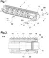
- the Fig. 1 shows a schematic exploded view of a forend 1 with housing 11 and built-in spacer 12, which is not essential to the invention and is therefore not explained further. Also shown is a clamping device 2 according to the invention with a lever 21, a nut 28 and a locking ring 281; a coordinate system used variously in the description and the claims 51-running direction, shaft direction, forward; 52-transverse direction to the left and 53-vertical direction upwards are entered for better orientation.
- the Fig. 2 shows section II-II of the Fig. 1 , an axial section through the shaft axis 41, thus parallel to the barrel axis.
- the barrel 15 is radially closest to the barrel axis (parallel or coinciding with the shaft axis 41), a barrel nut 13 in the form of an elongated sleeve is optionally pushed onto it and connected to the upper housing 14 at its rear end by means of a screw connection 42.
- This means that a collar of the barrel 15 is pressed by a rear end face of the barrel nut 13 against a front end face of the upper housing 14 and the barrel 15 itself is held in place.
- the housing 11 of the forend 1 not only encloses the barrel 15 including the barrel nut 13, but also a gas pipe 16.
- An annular groove 131 is provided in the running nut 13, the lever 21 lies partly in this annular groove and is cut in the area of its middle piece 26 in this illustration.
- the housing 11 there is an elongated hole running in the transverse direction 52 provided, the cross section of which has circular end sections two mutually parallel elongated hole axes 191, 192 running in the transverse direction 52. These axes lie in a plane normal to the vertical 52.
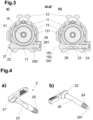
- the Figs. 3a ,b are a section along line III-III of the Fig. 1 , thus normal to the shaft axis 41, and represent two different clamping situations.
- the structure itself is as follows: The lever 21 is pushed with its threaded end first through the elongated hole 19, the nut 28 with its cone 282 is directed towards the weapon, screwed on and secured against loss by means of the resilient locking ring 281. By screwing on the nut 28, a longitudinal slot 17 in the housing 11 or the spacer 12 in the area of the lever 21 is changed in width and, together with the conical sections 22 of the shaft and 282 of the nut, ensures pretension and adjustment.
- the ones in the Figs. 4a ,b Clamping device 2 shown in detail consists of a lever 21 with a shaft with a lever axis 291, in one end region of which a thread 24 is provided, and at the other end of which a lever arm 27 projects approximately at a right angle.
- the diameter of the shaft increases conically towards the lever arm 27 and forms a clamping cone 22.
- the shaft has a recess 23 on the middle piece 26, approximately in the middle, which forms a generally cylindrical, preferably circular-cylindrical, lateral surface; in the exemplary embodiment, the generatrixes of the lateral surface run parallel to the plane defined by the lever axis and the lever arm 27.
- the thread 24 does not extend to the end of the shaft, but ends at an annular groove 25 whose inner diameter is smaller than the diameter of the thread base.
- the shaft diameter in the immediate end area is larger than that of the groove, but smaller than that of the thread base.
- a nut 28 interacts with the thread 24 of the shaft and is in the Figs. 5a -c is shown.
- This nut 28 is provided in a first axial region with an internal thread that can cooperate with the thread 24; in a second axial region it has a cylindrical bore (recess) with a larger diameter than the shaft diameter. This recess runs over the entire remaining length (actually height) of the nut 28.
- the outer contour of the nut is cylindrical with a subsequent conical taper towards the end, and in the second, an external hexagon is provided.
- FIG. 6a ,b An aspect of the invention that is also important in one embodiment lies in the design of the in the Figs. 6a ,b elongated hole 19 shown in more detail, which, as already mentioned, has two elongated hole axes 191, 192 running parallel to one another.
- the assembly is carried out with the lever 21 in the "OPEN” position until it stops on the "Upper”, then the nut 28 is tightened, narrowing the gap 17 and thus fixing the housing 5 to the running nut 128.
- This situation is essentially in Figs.7a -c shown.
- the first elongated hole axis 191 is further away from the upper housing 14 than the second elongated hole axis 192.
- Fig. 7a the housing 11 with the clamping device 2 is placed in the "OPEN" position, the lever axis 291 is at a distance from the second elongated hole axis 192 and is closer to the upper housing than this.
- the Fig. 7b shows the situation when turning the lever 21 into the "LOCKED" position, the two axes have become much closer to each other and can also coincide.
- Fig. 7c shows the situation after tightening the clamping nut 28, since the clamping surface 18, which is conical around the axis 191, as the arrow indicates, causes a load/displacement of the housing 11 of the forend 1 in the direction of the upper housing 14, thus stable mechanical conditions prevail .
- the invention thus enables tangential and axial clamping of the forend at the same time.
- the outer diameter of the nut 28 is selected such that a part of the weapon, preferably the slider (not shown), can be used to loosen the nut 28.
- the slider 28 with its slot-shaped opening, which allows the hammer or striker to pass through, can be used to screw on or unscrew the nut 28.
- a “half-inch” width of the nut head is therefore particularly preferred.
- substantially means a deviation of up to 10% of the specified value, if physically possible, both downwards and upwards, otherwise only in the sensible direction, for degrees (angle and temperature) This means ⁇ 10°.
Description
Die Erfindung betrifft einen Vorderschaft zur klemmenden Montage auf eine vorliegende Schusswaffe, insbesondere eines Gewehrs (Karabiners), vereinfacht auch Vorderschaftklemmung oder nur Klemmung genannt, speziell für Waffen des Gewehrtyps M4/M16/AR15, entsprechend dem Oberbegriff des Anspruches 1 und der
Aus der
Bei zahlreichen Gewehren (Karabinern), insbesondere solchen der genannten Typen sind seit vielen Jahren Vorderschäfte als selbstständige Teile bekannt und im Handel erhältlich, die die unterschiedlichsten Wünsche erfüllen. Es wird daher im Folgenden und in den Ansprüchen der Karabiner als existierend vorausgesetzt, die Erfindung betrifft einen an diesen angepassten Vorderschaft, der somit geometrisch und funktionell an die Waffe passt, sodass diese mit dem erfindungsgemäßen Vorderschaft verwendet werden kann. Als allgemeinen technologischen Hintergrund kann man kurz Folgendes angeben:
Vorderschäfte bilden einerseits einen Griffbereich für die freie Hand - die Zielhand - des Schützen aus und dienen als Schutz vor Verbrennungen am heißen Lauf. Andererseits schützt ein Vorderschaft den Lauf vor Schlägen, Schmutz, etc. und kann als Aufnahme für eine Vielzahl von Accessoires, wie etwa Zielfernrohre, Restlichtverstärker, Taschenlampen, Laserpointer, und vielem mehr, genutzt werden.For many rifles (carbines), especially those of the types mentioned, fore-stocks have been known as independent parts for many years and are commercially available and fulfill a wide variety of requirements. It is therefore assumed in the following and in the claims of the carbine that the invention relates to a fore-end adapted to the carbine, which therefore fits geometrically and functionally to the weapon so that it can be used with the fore-end according to the invention. As a general technological background one can briefly state the following:
On the one hand, forends form a grip area for the shooter's free hand - the aiming hand - and serve as protection against burns from the hot barrel. On the other hand, a forend protects the barrel from impacts, dirt, etc. and can be used as a holder for a variety of accessories, such as rifle scopes, low-light amplifiers, flashlights, laser pointers, and much more.
Der Vorderschaft kann als eine Art Verlängerung des Gehäuses eines Gewehrs in Laufrichtung verstanden werden. Um die Präzision eines Gewehrs zu verbessern, muss daher der Vorderschaft relativ zum Lauf und demnach auch relativ zum Gehäuse möglichst steif mit dem Gehäuse verbunden sein. Dabei muss der Lauf jedoch bei der Schussabgabe "frei" schwingen können.The forend can be understood as a kind of extension of the housing of a rifle in the direction of the barrel. In order to improve the precision of a rifle, the forend must be connected to the housing as rigidly as possible relative to the barrel and therefore also relative to the housing. However, the barrel must be able to swing “freely” when the shot is fired.
Die Befestigung des Laufes am Gehäuse erfolgt in der Regel mittels einer Laufmutter, welche zumeist als Überwurfmutter ausgeführt und mit dem Gehäuse verschraubt ist. Die Laufmutter drückt dabei den Lauf an einen radial vorspringenden Absatz des Gehäuses.The barrel is usually attached to the housing using a barrel nut, which is usually designed as a union nut and is screwed to the housing. The barrel nut presses the barrel against a radially projecting shoulder of the housing.
Aus dem Stand der Technik sind für Gewehre des Typs AR-15 eine Vielzahl von Möglichkeiten bekannt, um einen Vorderschaft mit dem Gehäuse zu koppeln, wobei sehr häufig eine Klemmung in Umfangsrichtung, also tangential zur Schaftachse, die im Folgenden, wenn sich aus dem Zusammenhang nichts anderes ergibt, auch bei Verwendung des Begriffes "axiale Richtung" die Bezugsachse, vorgenommen wird. Zumeist ist eine Verspannung entgegen der Laufrichtung, also gegen das Obergehäuse, mittels einer eigenen, zweiten, Klemmvorrichtung realisiert.From the prior art, a variety of options are known for AR-15 type rifles to couple a forend to the housing, very often involving a clamping in the circumferential direction, i.e. tangential to the stock axis, which is described below when taken out of context nothing else results, even if the term “axial direction” is used, the reference axis. In most cases, tensioning against the running direction, i.e. against the upper housing, is achieved by means of a separate, second clamping device.
Es bleibt der Wunsch nach einer schnellen De-/Montage des Vorderschaftes, ob im Einsatz oder auch zu Wartungszwecken. Ferner soll der Zerlege- bzw. Zusammenbauvorgang möglichst einfach vorgenommen werden können. Häufig sind spezielle Werkzeuge erforderlich, welche natürlich separat mitgeführt werden müssen. Oftmals erfolgt die tangentiale Klemmung über Schrauben, welche den Vorderschaft tangential an die Laufmutter klemmen wie beispielhaft in der
Einen ähnlichen Ansatz verfolgt die
In der Regel ist eine Mehrzahl von Bauteilen erforderlich, um eine Klemmung zumindest in tangentialer Richtung auszubilden. Eine Sicherung und Vorspannung des Laufs in axialer Richtung, vorzugsweise ebenfalls über eine Klemmung, wäre ebenfalls wünschenswert, um eine möglichst starre Verbindung zwischen Gehäuse und Vorderschaft auszubilden.As a rule, a plurality of components are required to form a clamping at least in the tangential direction. Securing and pre-tensioning the barrel in the axial direction, preferably also via a clamp, would also be desirable in order to form the most rigid connection possible between the housing and forend.
Die Aufgabe der vorliegenden Erfindung liegt somit darin, eine Klemmvorrichtung zur Verfügung zu stellen, welche eine Sicherung des Vorderschafts gegen Verschieben gegenüber dem Gehäuse und zugleich eine steife Anbindung an das Gehäuse gewährleistet. Eine weitere Aufgabe der Erfindung liegt darin, dass eine möglichst geringe Anzahl an Bauteilen für die Klemmvorrichtung verwendet wird. Ferner liegt eine Aufgabe der Erfindung darin, eine einfach handhabbare, gut zu wartende und relativ einfach aufgebaute Klemmvorrichtung zur Verfügung zu stellen.The object of the present invention is therefore to provide a clamping device which secures the forend against displacement relative to the housing and at the same time ensures a rigid connection to the housing. A further object of the invention is that the smallest possible number of components is used for the clamping device. A further object of the invention is to provide a clamping device that is easy to handle, easy to maintain and has a relatively simple structure.
Diese Aufgabe wird durch die im Anspruch 1 angegebenen Merkmale gelöst.This task is solved by the features specified in claim 1.
Es wird in der Beschreibung und den Ansprüchen "vor" bzw. "(nach) vorne" als Richtung zur Mündung des Laufes hin, "(nach) hinten" als Richtung zum Schaft hin, "(nach) unten" als Richtung für den Verschluss zum Magazin hin, und "(nach) oben" als Richtung vom Magazin weg benutzt. Die Bezeichnungen "Waffenmittelebene", "Laufseele", "Laufachse", "Seelenachse", etc. haben die übliche Bedeutung, die der Fachmann ihnen im Stand der Technik beimisst. "Links" ist somit auf die Waffenmittelebene bezogen, "von links" entspricht einer Bewegung, Betätigung, Kraftausübung in Richtung der Waffenmittelebene, ausgehend von einer "links" von ihr liegenden Ausgangsposition, etc.. Es wird der Verschluss unter der Wirkung der Gase nach der Abgabe eines Schusses "nach hinten" bewegt und gelangt unter der Wirkung einer Schließfeder wieder "nach vorne", etc..In the description and the claims it is used "in front" or "(to) the front" as the direction towards the muzzle of the barrel, "(to) the rear" as the direction towards the stock, "(to) the bottom" as the direction for the breech towards the magazine, and "(up)" used as the direction away from the magazine. The terms "weapon midlevel", "running soul", "running axis", "soul axis", etc. have the usual meaning that the person skilled in the art attaches to them in the prior art. “Left” is therefore related to the center plane of the weapon, “from the left” corresponds to a movement, actuation, exertion of force in the direction of the center plane of the weapon, starting from an initial position “to the left” of it, etc. The breech moves under the effect of the gases When a shot is fired, it moves “backward” and then moves “forward” again under the action of a recoil spring, etc.
Die Erfindung wird im Folgenden anhand der Zeichnungen näher erläutert. Dabei zeigt bzw. zeigen:
- die
Fig. 1 eine schematische Explosionsdarstellung eines Vorderschafts, - die
Fig. 2 den Schnitt II-II derFig. 1 , - die
Figs. 3a,b den Schnitt III-III derFig. 1 in zwei unterschiedlichen Klemmsituationen, - die
Figs. 4a,b einen Hebel in zwei unterschiedlichen perspektivischen Ansichten, - die
Figs. 5a-c eine Mutter in unterschiedlichen Ansichten, - die
Figs. 6a,b ein Detail am Vorderschaft in unterschiedlichen Ansichten und - die
Figs. 7a-c unterschiedliche Klemmsituationen in einem axialen Schnitt.
- the
Fig. 1 a schematic exploded view of a forend, - the
Fig. 2 the section II-II of theFig. 1 , - the
Figs. 3a,b the section III-III of theFig. 1 in two different clamping situations, - the
Figs. 4a,b a lever in two different perspective views, - the
Figs. 5a-c a mother with different views, - the
Figs. 6a,b a detail on the forend in different views and - the
Figs. 7a-c different clamping situations in an axial section.
In den Figuren wurde möglichst alles, was den Vorderschaft 1 ohne die Klemmvorrichtung betrifft, mit "1n" bezeichnet, analog dazu möglichst alles, was die Klemmvorrichtung 2 betrifft mit "2n".In the figures, everything that concerns the forend 1 without the clamping device was labeled "1n", and similarly everything that concerns the
In den
Die
Die
In der Laufmutter 13 ist eine Ringnut 131 vorgesehen, der Hebel 21 liegt zum Teil in dieser Ringnut wird in dieser Darstellung im Bereich seines Mittelstückes 26 geschnitten. Im Gehäuse 11 ist ein in Querrichtung 52 verlaufendes Langloch vorgesehen, dessen Querschnitt kreisrunde Endabschnitte zwei zueinander parallele, in Querrichtung 52 verlaufende, Langlochachsen 191, 192, aufweist. Diese Achsen liegen in einer Ebene normal zur Vertikalen 52.An
Die
Der Aufbau selbst ist folgender: Der Hebel 21 ist mit seinem Gewinde-Ende voran durch das Langloch 19 geschoben, die Mutter 28 mit ihrem Konus 282 zur Waffe gerichtet, aufgeschraubt und mittels des federnden Sicherungsringes 281 gegen Verlust gesichert. Durch das Aufschrauben der Mutter 28 wird ein Längsschlitz 17 des Gehäuses 11 bzw. des Distanzhalters 12 im Bereich des Hebels 21 in seiner Breite verändert und sorgt mit den konischen Abschnitten 22 des Schaftes und 282 der Mutter für eine Vorspannung und Justierung.The structure itself is as follows: The lever 21 is pushed with its threaded end first through the
Die
der Ringnut 131der Laufmutter 13,- des Langloches 19 des Gehäuses 11 und
- des Schaftes des Hebels 21
- the
annular groove 131 of the runningnut 13, - the
elongated hole 19 of thehousing 11 and - the shaft of the lever 21
Die in den
Mit dem Gewinde 24 des Schaftes wirkt eine Mutter 28 zusammen, die in den
Durch die Verdrehung des Hebelarms 27 in der Einbauposition (siehe
Ein in einer Ausgestaltung ebenfalls bedeutender Aspekt der Erfindung liegt in der Ausbildung des in den
Die Montage erfolgt mit dem Hebel 21 in der "OFFEN" Position bis zum Anschlag auf den "Upper", dann wird die Mutter 28 angezogen, verengt den Spalt 17 und fixiert so das Gehäuse 5 an der Laufmutter 128. Diese Situation ist im Wesentlichen in
In
Die
Die
Somit ermöglicht die Erfindung gleichzeitig eine tangentiale und axiale Klemmung des Vorderschaftes.The invention thus enables tangential and axial clamping of the forend at the same time.
Im dargestellten Ausführungsbeispiel ist der Außendurchmesser der Mutter 28 so gewählt, dass ein Teil der Waffe, vorzugsweise das Gleitstück (nicht dargestellt), zum Lösen der Mutter 28 verwendet werden kann. Dies bedeutet, dass man das Gleitstück 28 mit seiner schlitzförmigen Öffnung, welche den Durchtritt des Hammers bzw. Schlagstücks ermöglicht, zum Auf-Abschrauben der Mutter 28 verwenden kann. Somit ist eine "halb-zöllige" Weite des Mutterkopfs besonders bevorzugt.In the illustrated embodiment, the outer diameter of the
Weitere Ausgestaltungen betreffen die bereits erläuterte Verlustsicherung der Klemmvorrichtung durch die Ringnut 25 am Hebel 21 in Verbindung mit dem Sicherungsring 281, der ein vollständiges Abschrauben der Mutter und damit deren Verlust verhindert.Further refinements relate to the already explained protection against loss of the clamping device through the
Es ist für den Fachmann klar, dass die dargestellten und beschriebenen Ausführungsformen als beispielhaft anzusehen sind, in Kenntnis der Erfindung kann er diese problemlos auf andere Waffen übertragen und anpassen. Die zu verwendenden Materialien sind die gleichen wie im Stand der Technik, die Verarbeitung bzw. die zu wählenden Herstellungsverfahren ebenso.It is clear to the person skilled in the art that the illustrated and described embodiments are to be viewed as exemplary; knowing the invention, he can easily transfer and adapt them to other weapons. The materials to be used are the same as in the prior art, as is the processing and the manufacturing processes to be chosen.
In der Beschreibung und den Ansprüchen werden die Begriffe "vorne", "hinten", "oben", "unten" und so weiter in der landläufigen Form und unter Bezugnahme auf den Gegenstand in seiner üblichen Gebrauchslage gebraucht. Das heißt, dass bei einer Waffe die Mündung des Laufes "vorne" ist, dass der Verschluss bzw. Schlitten durch die Explosionsgase nach "hinten" bewegt wird, etc.. Quer zu einer Richtung meint im Wesentlichen eine um 90° dazu gedrehte Richtung, soferne nichts anderes angegeben ist, auf das verschiedentlich in den Figuras eingezeichnete und beschriebene Koordinatensystem 51- Laufrichtung, 52 - Querrichtung und 53 - Vertikale (bei üblicher Haltung der Waffe im Anschlag) wird zur besseren Orientierung speziell hingewiesen.In the description and claims, the terms "front", "rear", "top", "bottom" and so on are used in the common form and with reference to the article in its usual position of use. This means that in a weapon the muzzle of the barrel is "front", that the breech or slide is moved "backwards" by the explosion gases, etc. Transverse to a direction essentially means a direction rotated by 90° to it, Unless otherwise stated, special reference is made to the coordinate system 51 - running direction, 52 - transverse direction and 53 - vertical (with the usual position of the weapon at the ready), which are drawn and described variously in the figures, for better orientation.
Es soll noch darauf hingewiesen werden, dass in der Beschreibung und den Ansprüchen Angaben wie "unterer Bereich" eines Gegenstandes die untere Hälfte und insbesondere das untere Viertel der Gesamthöhe bedeutet, "unterster Bereich" das unterste Viertel und insbesondere einen noch kleineren Teil; während "mittlerer Bereich" das mittlere Drittel der Gesamthöhe (Breite - Länge) meint. All diese Angaben haben ihre landläufige Bedeutung, angewandt auf die bestimmungsgemäße Position des betrachteten Gegenstandes, soferne nichts anderes angegeben ist.It should also be pointed out that in the description and the claims, information such as "lower area" of an object means the lower half and in particular the lower quarter of the total height, and "lowest area" means the lowest quarter and especially an even smaller part; while "middle area" means the middle third of the total height (width - length). All of this information has its common meaning, applied to the intended position of the item under consideration, unless otherwise stated.
In der Beschreibung und den Ansprüchen bedeutet "im Wesentlichen" eine Abweichung von bis zu 10 % des angegebenen Wertes, wenn es physikalisch möglich ist, sowohl nach unten als auch nach oben, ansonsten nur in die sinnvolle Richtung, bei Gradangaben (Winkel und Temperatur) sind damit ± 10° gemeint.In the description and claims, "substantially" means a deviation of up to 10% of the specified value, if physically possible, both downwards and upwards, otherwise only in the sensible direction, for degrees (angle and temperature) This means ± 10°.
Alle Mengenangaben und Anteilsangaben, insbesondere solche zur Abgrenzung der Erfindung, soweit sie nicht die konkreten Beispiele betreffen, sind mit ± 10 % Toleranz zu verstehen, somit beispielsweise: 11 % bedeutet: von 9,9 % bis 12,1 %. Bei Bezeichnungen wie bei: "ein Lösungsmittel" ist das Wort "ein" nicht als Zahlwort, sondern als unbestimmter Artikel oder als Fürwort anzusehen, wenn nicht aus dem Zusammenhang etwas anderes hervorgeht.All quantities and proportions, in particular those defining the invention, as long as they do not relate to the specific examples, are to be understood with a tolerance of ± 10%, so for example: 11% means: from 9.9% to 12.1%. In terms such as: "a solvent", the word "a" is not to be viewed as a numeral, but rather as an indefinite article or as a pronoun, unless the context indicates otherwise.
Der Begriff: "Kombination" bzw. "Kombinationen" steht, soferne nichts anderes angegeben, für alle Arten von Kombinationen, ausgehend von zwei der betreffenden Bestandteile bis zu einer Vielzahl oder aller derartiger Bestandteile, der Begriff: "enthaltend" steht auch für "bestehend aus".The term: "combination" or "combinations" stands, unless otherwise stated, for all types of combinations, starting from two of the components in question up to a large number or all of such components; the term: "containing" also stands for "existing out of".
Die in den einzelnen Ausgestaltungen und Beispielen angegebenen Merkmale und Varianten können mit denen der anderen Beispiele und Ausgestaltungen frei kombiniert und insbesondere zur Kennzeichnung der Erfindung in den Ansprüchen ohne zwangläufige Mitnahme der anderen Details der jeweiligen Ausgestaltung bzw. des jeweiligen Beispiels verwendet werdenThe features and variants specified in the individual embodiments and examples can be freely combined with those of the other examples and embodiments and can be used in particular to characterize the invention in the claims without necessarily including the other details of the respective embodiment or example
Zum einfacheren Verständnis der Erfindung sind die englischen Begriffe, welche auch als Synonym verwendet werden können, in der nachfolgenden Bezugszeichenliste angegeben.
Claims (2)
- Handguard for clamping mounting on an existing firearm, in particular on its barrel (15) or its barrel nut (13), the barrel (15) or the barrel nut (13) having an annular groove (281), comprising:- a shaft housing (11) with a shaft axis (41), which has a slit (17) running radially thereto and a through-opening running in the transverse direction (52) for a clamping device,- a clamping device (2) for the shaft housing (11), comprising∘ a lever (21) having a center element (26) which surrounds the lever axis (291) and lies in a through-opening of the shaft housing (11) in a normal plane with respect to the shaft axis (41), and which has a recess (23) in its center area, a thread (24) at one end portion and a lever arm (27) at the other end, and∘ a nut (28) with an internal thread matching the thread (24);whereby the center element (26) is provided at its end portion directed towards the lever arm (27) with a clamp taper socket (22) widening towards the lever arm (27) and contacts a conical clamping surface (18) of the shaft housing (11);whereby, in the assembled state, the nut (28) is screwed onto the thread (24) and thus narrows the slit (17), and the angular position of the lever (21) about its lever axis (291) is such that its center element (26) contacts the annular groove (281),characterized in that, the nut (28) is provided on its outer side with a conical area, a clamp taper socket (282), in that, in the shaft housing (11), the through-opening for receiving the center element (26) is a long hole (19) with an outline comprised of two semicircles with a first axis (191) and a second axis (192) parallel thereto and a rectangle located in-between, and in that the long hole (19) is provided on both ends with conical clamp surfaces (18), which are centric around the first axis (191) and co-operate with the clamp taper sockets (22, 282).
- Handguard according to claim 1, characterized in that the center element (26) is provided with an annular groove (25) at its end portion having the thread (24), and in that the nut (28) has the internal thread in a first axial section, and in that a bore with a larger diameter is formed in a second axial section, and in that a safety ring (31) is inserted into the annular groove (25).
Priority Applications (5)
| Application Number | Priority Date | Filing Date | Title |
|---|---|---|---|
| BR112022011131A BR112022011131A2 (en) | 2019-12-13 | 2020-11-23 | HAND PROTECTOR FOR FIXING THE ASSEMBLY OF AN EXISTING FIREGUN |
| PCT/EP2020/083075 WO2021121877A1 (en) | 2019-12-13 | 2020-11-23 | Handguard for clamping mounting on an existing firearm |
| US17/757,291 US11892260B2 (en) | 2019-12-13 | 2020-11-23 | Handguard for clamping mounting on an existing firearm |
| CA3163898A CA3163898A1 (en) | 2019-12-13 | 2020-11-23 | Handguard for clamping mounting on an existing firearm |
| IL293577A IL293577A (en) | 2019-12-13 | 2020-11-23 | Handguard for clamping mounting on an existing firearm |
Applications Claiming Priority (1)
| Application Number | Priority Date | Filing Date | Title |
|---|---|---|---|
| EP19215974.7A EP3835706B1 (en) | 2019-12-13 | 2019-12-13 | Adapter for mounting an accessory to a firearm |
Publications (3)
| Publication Number | Publication Date |
|---|---|
| EP3835708A1 EP3835708A1 (en) | 2021-06-16 |
| EP3835708B1 true EP3835708B1 (en) | 2023-12-06 |
| EP3835708C0 EP3835708C0 (en) | 2023-12-06 |
Family
ID=68916369
Family Applications (2)
| Application Number | Title | Priority Date | Filing Date |
|---|---|---|---|
| EP19215974.7A Active EP3835706B1 (en) | 2019-12-13 | 2019-12-13 | Adapter for mounting an accessory to a firearm |
| EP19216891.2A Active EP3835708B1 (en) | 2019-12-13 | 2019-12-17 | Front shaft for clamping on an existing weapon |
Family Applications Before (1)
| Application Number | Title | Priority Date | Filing Date |
|---|---|---|---|
| EP19215974.7A Active EP3835706B1 (en) | 2019-12-13 | 2019-12-13 | Adapter for mounting an accessory to a firearm |
Country Status (6)
| Country | Link |
|---|---|
| US (2) | US11892260B2 (en) |
| EP (2) | EP3835706B1 (en) |
| BR (1) | BR112022011131A2 (en) |
| CA (1) | CA3163898A1 (en) |
| IL (1) | IL293577A (en) |
| WO (1) | WO2021121877A1 (en) |
Families Citing this family (6)
| Publication number | Priority date | Publication date | Assignee | Title |
|---|---|---|---|---|
| USD1015475S1 (en) * | 2019-12-05 | 2024-02-20 | Glock Technology Gmbh | Firearm upper receiver |
| US20220196364A1 (en) * | 2020-12-17 | 2022-06-23 | James Matthew Underwood | Handguard |
| US20220252374A1 (en) * | 2021-02-11 | 2022-08-11 | Jason Louthan | Modular handguard for firearm |
| US20220282951A1 (en) * | 2021-03-04 | 2022-09-08 | Bowden Tactical, LLC | Interchangeable handguard system |
| US11725904B2 (en) * | 2021-11-23 | 2023-08-15 | Strike IP, LLC | Firearm handguard with bridge adapter |
| EP4194795A1 (en) | 2021-12-10 | 2023-06-14 | Glock Technology GmbH | Device for forming a secondary attachment of a front shaft |
Family Cites Families (34)
| Publication number | Priority date | Publication date | Assignee | Title |
|---|---|---|---|---|
| US968583A (en) * | 1909-08-12 | 1910-08-30 | Onesime E Michaud | Attachment for shotguns. |
| US985308A (en) * | 1911-01-09 | 1911-02-28 | Jesse Owen Van Voorhis | Firearm. |
| US2880435A (en) * | 1955-01-18 | 1959-04-07 | Herman T Hale | Pipe cleaning apparatus |
| US4887929A (en) * | 1988-04-25 | 1989-12-19 | Electric Eel Manufacturing Co., Inc. | Cable coupler |
| US4920679A (en) * | 1988-09-21 | 1990-05-01 | Sarles J Stephen | Firearm with detachable barrel |
| US4893426A (en) * | 1988-10-07 | 1990-01-16 | South Central Research Corp. | Lugged coupling apparatus |
| US5271312A (en) * | 1990-12-14 | 1993-12-21 | Colt's Manufacturing Company Inc. | Locating spring and plunger assembly for a firearm |
| US5433133A (en) * | 1994-03-07 | 1995-07-18 | La France; Timothy F. | Quick detachable gun barrel coupling member |
| US5559302A (en) * | 1995-08-31 | 1996-09-24 | Gsl Technology, Inc. | Bayonet type coupling for firearms |
| US6873185B2 (en) | 2002-06-19 | 2005-03-29 | Viasic, Inc. | Logic array devices having complex macro-cell architecture and methods facilitating use of same |
| KR100686794B1 (en) | 2005-01-25 | 2007-02-23 | 삼성에스디아이 주식회사 | Battery monitoring system and its method |
| US7523580B1 (en) * | 2005-11-07 | 2009-04-28 | Jerome Benedict Tankersley | Handguard system integrated to a firearm |
| US7516690B2 (en) * | 2006-12-22 | 2009-04-14 | Mcclellan W Thomas | Firearm suppressor, mounting system and mounting method |
| EP2247908A2 (en) * | 2008-02-21 | 2010-11-10 | George Koumbis | Assembly and noise suppressor for firearms |
| US9021673B2 (en) * | 2011-02-26 | 2015-05-05 | Steven Ray | Snake glove |
| CZ2011445A3 (en) * | 2011-07-21 | 2012-09-19 | Proarms Armory S. R. O. | Arrangement for exchange and securing barrel of a long firearm |
| NO333615B1 (en) * | 2011-11-29 | 2013-07-22 | A Tec Holding As | Muffler for weapons |
| US8819980B2 (en) | 2012-11-12 | 2014-09-02 | WHG Properties, LLC | Modular rifle handguard |
| US9175919B2 (en) * | 2013-08-16 | 2015-11-03 | Travis Russell | System and method for attaching a sound suppressor to a firearm |
| US8931196B1 (en) * | 2013-11-18 | 2015-01-13 | Mark C. LaRue | Firearm having capability for field assembly and disassembly |
| US20150377584A1 (en) * | 2014-06-25 | 2015-12-31 | Ati Ip, Llc | Forend-mounted heatshield arrangement for firearms |
| US9658010B1 (en) * | 2014-10-13 | 2017-05-23 | Paul Oglesby | Heat shielding and thermal venting system |
| US10107582B2 (en) * | 2015-12-04 | 2018-10-23 | Scott Gray | Quick connect rifle receiver adapter system |
| US9513078B1 (en) * | 2016-05-17 | 2016-12-06 | Precision Tooling Products, LLC | Quick mount firearm barrel accessory |
| US10641573B2 (en) * | 2017-02-27 | 2020-05-05 | Strike Industries, Inc. | Lock mechanism for muzzle shroud and blast diffuser using the same |
| US10274279B2 (en) * | 2017-04-27 | 2019-04-30 | Dbdrop Inc. | Firearm suppressor adapter for firearm rails |
| US11047640B1 (en) * | 2017-11-21 | 2021-06-29 | Stwip Llc | Device for dampening residual effects from a firearm suppressor |
| US10480897B2 (en) * | 2017-11-29 | 2019-11-19 | Occam Defense Solutions Inc. | Handguard system for firearms |
| US10352650B2 (en) * | 2017-12-01 | 2019-07-16 | Spec Arms LLC | Firearm handguard securement system and related method |
| US10801798B2 (en) * | 2017-12-29 | 2020-10-13 | Super Dave Designs, LLC | Barrel mounting system |
| US11187474B2 (en) * | 2018-01-09 | 2021-11-30 | William E. Masters | Compact shotgun, multipurpose mount, and trigger assembly |
| US10436549B1 (en) * | 2018-10-02 | 2019-10-08 | 5th Axis, Inc. | Rifle handguard system |
| US10775129B1 (en) * | 2019-09-20 | 2020-09-15 | Bravo Company Mfg, Inc. | Handguard mount with tie bar |
| US11408702B2 (en) * | 2020-06-16 | 2022-08-09 | Austin Reis-Green | Firearm muzzle accessory coupling device, system and method |
-
2019
- 2019-12-13 EP EP19215974.7A patent/EP3835706B1/en active Active
- 2019-12-17 EP EP19216891.2A patent/EP3835708B1/en active Active
-
2020
- 2020-11-23 US US17/757,291 patent/US11892260B2/en active Active
- 2020-11-23 WO PCT/EP2020/083075 patent/WO2021121877A1/en active Application Filing
- 2020-11-23 BR BR112022011131A patent/BR112022011131A2/en unknown
- 2020-11-23 CA CA3163898A patent/CA3163898A1/en active Pending
- 2020-11-23 IL IL293577A patent/IL293577A/en unknown
- 2020-12-14 US US17/120,695 patent/US11391532B2/en active Active
Also Published As
| Publication number | Publication date |
|---|---|
| US20210180903A1 (en) | 2021-06-17 |
| EP3835706B1 (en) | 2023-10-18 |
| US11892260B2 (en) | 2024-02-06 |
| US11391532B2 (en) | 2022-07-19 |
| EP3835708A1 (en) | 2021-06-16 |
| EP3835706C0 (en) | 2023-10-18 |
| WO2021121877A1 (en) | 2021-06-24 |
| CA3163898A1 (en) | 2021-06-24 |
| EP3835706A1 (en) | 2021-06-16 |
| US20230020437A1 (en) | 2023-01-19 |
| EP3835708C0 (en) | 2023-12-06 |
| IL293577A (en) | 2022-08-01 |
| BR112022011131A2 (en) | 2022-08-23 |
Similar Documents
| Publication | Publication Date | Title |
|---|---|---|
| EP3835708B1 (en) | Front shaft for clamping on an existing weapon | |
| DE2057995C3 (en) | Barrel mount for exchangeable barrels on handguns | |
| DE3522027C2 (en) | ||
| EP2339287B1 (en) | Clamping system for accessories on a Picatinny rail | |
| EP1924815B1 (en) | Gas cylinder block and handgun | |
| EP3420302B1 (en) | Firearm with removable barrel | |
| EP2458317B1 (en) | Mounting of a bolthandle for a repeater rifle | |
| DE102008007341A1 (en) | Additional handle for a handgun | |
| EP3649424B1 (en) | Device for adjusting the orientation of a rear stock of a portable firearm | |
| DE2157420A1 (en) | RIFLE BARREL FASTENING AND EXCHANGE DEVICE ON HANDGUNS | |
| EP4038337B1 (en) | Barrel unit for a firearm | |
| DE102012012917A1 (en) | Tilting mounting with additional stop | |
| EP1864073B1 (en) | Fastening system for fixing a component to a small arm and small arm comprising such a system | |
| DE102005037884B3 (en) | Adapter component for firearm has clamping element acting on it which is elastically deformed when adapter component is adjusted | |
| EP3699541B1 (en) | System for mounting of a sound suppressor to a barrel of a firearm | |
| AT522076B1 (en) | Upper case for a firearm | |
| EP3933337B1 (en) | Mounting device for releasably attaching a shaft to a system box of a firearm | |
| DE8012499U1 (en) | HUNTING GUN WITH ONE POCKET RIFLE | |
| AT516501B1 (en) | Firearm of turret type | |
| DE102017102005A1 (en) | Handgun with tool-less removable and mountable butt stock | |
| EP4027099B1 (en) | Fire selection unit for a firearm | |
| DE3403050A1 (en) | Push-in barrel for large-calibre firearms | |
| DE406610C (en) | Attachment of the barrel to the lock housing of firearms | |
| DE202016102404U1 (en) | Adapter, combination, gun barrel, gun barrel adapter and weapon system | |
| DE102021128018A1 (en) | Attachment system for sonic weapon accessories |
Legal Events
| Date | Code | Title | Description |
|---|---|---|---|
| PUAI | Public reference made under article 153(3) epc to a published international application that has entered the european phase |
Free format text: ORIGINAL CODE: 0009012 |
|
| STAA | Information on the status of an ep patent application or granted ep patent |
Free format text: STATUS: THE APPLICATION HAS BEEN PUBLISHED |
|
| AK | Designated contracting states |
Kind code of ref document: A1 Designated state(s): AL AT BE BG CH CY CZ DE DK EE ES FI FR GB GR HR HU IE IS IT LI LT LU LV MC MK MT NL NO PL PT RO RS SE SI SK SM TR |
|
| STAA | Information on the status of an ep patent application or granted ep patent |
Free format text: STATUS: REQUEST FOR EXAMINATION WAS MADE |
|
| 17P | Request for examination filed |
Effective date: 20211209 |
|
| RBV | Designated contracting states (corrected) |
Designated state(s): AL AT BE BG CH CY CZ DE DK EE ES FI FR GB GR HR HU IE IS IT LI LT LU LV MC MK MT NL NO PL PT RO RS SE SI SK SM TR |
|
| GRAP | Despatch of communication of intention to grant a patent |
Free format text: ORIGINAL CODE: EPIDOSNIGR1 |
|
| STAA | Information on the status of an ep patent application or granted ep patent |
Free format text: STATUS: GRANT OF PATENT IS INTENDED |
|
| RIC1 | Information provided on ipc code assigned before grant |
Ipc: F41A 21/44 20060101ALI20230627BHEP Ipc: F41C 23/16 20060101AFI20230627BHEP |
|
| INTG | Intention to grant announced |
Effective date: 20230717 |
|
| GRAS | Grant fee paid |
Free format text: ORIGINAL CODE: EPIDOSNIGR3 |
|
| GRAA | (expected) grant |
Free format text: ORIGINAL CODE: 0009210 |
|
| STAA | Information on the status of an ep patent application or granted ep patent |
Free format text: STATUS: THE PATENT HAS BEEN GRANTED |
|
| AK | Designated contracting states |
Kind code of ref document: B1 Designated state(s): AL AT BE BG CH CY CZ DE DK EE ES FI FR GB GR HR HU IE IS IT LI LT LU LV MC MK MT NL NO PL PT RO RS SE SI SK SM TR |
|
| REG | Reference to a national code |
Ref country code: GB Ref legal event code: FG4D Free format text: NOT ENGLISH |
|
| REG | Reference to a national code |
Ref country code: DE Ref legal event code: R096 Ref document number: 502019010073 Country of ref document: DE |
|
| REG | Reference to a national code |
Ref country code: CH Ref legal event code: EP |
|
| REG | Reference to a national code |
Ref country code: IE Ref legal event code: FG4D Free format text: LANGUAGE OF EP DOCUMENT: GERMAN |
|
| U01 | Request for unitary effect filed |
Effective date: 20231212 |
|
| U07 | Unitary effect registered |
Designated state(s): AT BE BG DE DK EE FI FR IT LT LU LV MT NL PT SE SI Effective date: 20231218 |
|
| PGFP | Annual fee paid to national office [announced via postgrant information from national office to epo] |
Ref country code: GB Payment date: 20231215 Year of fee payment: 5 |
|
| U20 | Renewal fee paid [unitary effect] |
Year of fee payment: 5 Effective date: 20231219 |
|
| PG25 | Lapsed in a contracting state [announced via postgrant information from national office to epo] |
Ref country code: GR Free format text: LAPSE BECAUSE OF FAILURE TO SUBMIT A TRANSLATION OF THE DESCRIPTION OR TO PAY THE FEE WITHIN THE PRESCRIBED TIME-LIMIT Effective date: 20240307 |