EP3835706A1 - Adapter for mounting an accessory to a firearm - Google Patents
Adapter for mounting an accessory to a firearm Download PDFInfo
- Publication number
- EP3835706A1 EP3835706A1 EP19215974.7A EP19215974A EP3835706A1 EP 3835706 A1 EP3835706 A1 EP 3835706A1 EP 19215974 A EP19215974 A EP 19215974A EP 3835706 A1 EP3835706 A1 EP 3835706A1
- Authority
- EP
- European Patent Office
- Prior art keywords
- adapter
- accessory
- casing
- handguard
- barrel
- Prior art date
- Legal status (The legal status is an assumption and is not a legal conclusion. Google has not performed a legal analysis and makes no representation as to the accuracy of the status listed.)
- Granted
Links
- 238000010168 coupling process Methods 0.000 claims abstract description 27
- 238000005859 coupling reaction Methods 0.000 claims abstract description 27
- 230000008878 coupling Effects 0.000 claims abstract description 24
- 230000000295 complement effect Effects 0.000 claims abstract description 4
- 230000003584 silencer Effects 0.000 claims description 9
- 238000009423 ventilation Methods 0.000 description 4
- 239000007789 gas Substances 0.000 description 3
- 230000017525 heat dissipation Effects 0.000 description 3
- 238000010438 heat treatment Methods 0.000 description 3
- 239000000470 constituent Substances 0.000 description 2
- 238000001816 cooling Methods 0.000 description 2
- 230000000694 effects Effects 0.000 description 2
- 208000030984 MIRAGE syndrome Diseases 0.000 description 1
- 230000015572 biosynthetic process Effects 0.000 description 1
- 230000000903 blocking effect Effects 0.000 description 1
- 239000000567 combustion gas Substances 0.000 description 1
- 238000010276 construction Methods 0.000 description 1
- 230000001934 delay Effects 0.000 description 1
- 238000004880 explosion Methods 0.000 description 1
- 230000014509 gene expression Effects 0.000 description 1
- 239000003365 glass fiber Substances 0.000 description 1
- 238000007689 inspection Methods 0.000 description 1
- 230000014759 maintenance of location Effects 0.000 description 1
- 238000000034 method Methods 0.000 description 1
- 230000003287 optical effect Effects 0.000 description 1
- 230000000149 penetrating effect Effects 0.000 description 1
- 230000008092 positive effect Effects 0.000 description 1
- 238000003825 pressing Methods 0.000 description 1
- TVLSRXXIMLFWEO-UHFFFAOYSA-N prochloraz Chemical compound C1=CN=CN1C(=O)N(CCC)CCOC1=C(Cl)C=C(Cl)C=C1Cl TVLSRXXIMLFWEO-UHFFFAOYSA-N 0.000 description 1
Images


Classifications
-
- F—MECHANICAL ENGINEERING; LIGHTING; HEATING; WEAPONS; BLASTING
- F41—WEAPONS
- F41A—FUNCTIONAL FEATURES OR DETAILS COMMON TO BOTH SMALLARMS AND ORDNANCE, e.g. CANNONS; MOUNTINGS FOR SMALLARMS OR ORDNANCE
- F41A21/00—Barrels; Gun tubes; Muzzle attachments; Barrel mounting means
- F41A21/32—Muzzle attachments or glands
- F41A21/325—Mountings for muzzle attachments
-
- F—MECHANICAL ENGINEERING; LIGHTING; HEATING; WEAPONS; BLASTING
- F41—WEAPONS
- F41A—FUNCTIONAL FEATURES OR DETAILS COMMON TO BOTH SMALLARMS AND ORDNANCE, e.g. CANNONS; MOUNTINGS FOR SMALLARMS OR ORDNANCE
- F41A21/00—Barrels; Gun tubes; Muzzle attachments; Barrel mounting means
- F41A21/30—Silencers
-
- F—MECHANICAL ENGINEERING; LIGHTING; HEATING; WEAPONS; BLASTING
- F41—WEAPONS
- F41A—FUNCTIONAL FEATURES OR DETAILS COMMON TO BOTH SMALLARMS AND ORDNANCE, e.g. CANNONS; MOUNTINGS FOR SMALLARMS OR ORDNANCE
- F41A21/00—Barrels; Gun tubes; Muzzle attachments; Barrel mounting means
- F41A21/44—Insulation jackets; Protective jackets
-
- F—MECHANICAL ENGINEERING; LIGHTING; HEATING; WEAPONS; BLASTING
- F41—WEAPONS
- F41A—FUNCTIONAL FEATURES OR DETAILS COMMON TO BOTH SMALLARMS AND ORDNANCE, e.g. CANNONS; MOUNTINGS FOR SMALLARMS OR ORDNANCE
- F41A21/00—Barrels; Gun tubes; Muzzle attachments; Barrel mounting means
- F41A21/48—Barrel mounting means, e.g. releasable mountings for replaceable barrels
- F41A21/481—Barrel mounting means, e.g. releasable mountings for replaceable barrels using partial or interrupted threads, e.g. bayonet-type mountings
-
- F—MECHANICAL ENGINEERING; LIGHTING; HEATING; WEAPONS; BLASTING
- F41—WEAPONS
- F41A—FUNCTIONAL FEATURES OR DETAILS COMMON TO BOTH SMALLARMS AND ORDNANCE, e.g. CANNONS; MOUNTINGS FOR SMALLARMS OR ORDNANCE
- F41A21/00—Barrels; Gun tubes; Muzzle attachments; Barrel mounting means
- F41A21/48—Barrel mounting means, e.g. releasable mountings for replaceable barrels
- F41A21/484—Barrel mounting means, e.g. releasable mountings for replaceable barrels using interlocking means, e.g. by sliding pins
-
- F—MECHANICAL ENGINEERING; LIGHTING; HEATING; WEAPONS; BLASTING
- F41—WEAPONS
- F41A—FUNCTIONAL FEATURES OR DETAILS COMMON TO BOTH SMALLARMS AND ORDNANCE, e.g. CANNONS; MOUNTINGS FOR SMALLARMS OR ORDNANCE
- F41A21/00—Barrels; Gun tubes; Muzzle attachments; Barrel mounting means
- F41A21/48—Barrel mounting means, e.g. releasable mountings for replaceable barrels
- F41A21/485—Barrel mounting means, e.g. releasable mountings for replaceable barrels using screws or bolts
-
- F—MECHANICAL ENGINEERING; LIGHTING; HEATING; WEAPONS; BLASTING
- F41—WEAPONS
- F41C—SMALLARMS, e.g. PISTOLS, RIFLES; ACCESSORIES THEREFOR
- F41C23/00—Butts; Butt plates; Stocks
- F41C23/16—Forestocks; Handgrips; Hand guards
Landscapes
- Engineering & Computer Science (AREA)
- General Engineering & Computer Science (AREA)
- Aiming, Guidance, Guns With A Light Source, Armor, Camouflage, And Targets (AREA)
- Clamps And Clips (AREA)
- Gripping Jigs, Holding Jigs, And Positioning Jigs (AREA)
Abstract
Die Erfindung betrifft einen Adapter (30) zur Montage eines Zubehörteils (40) an einer Feuerwaffe, ein entsprechend ausgebildetes Zubehörteil (40), sowie eine Ummantelung bzw. Handguard assembly (20) einer Feuerwaffe.Der Adapter (30) weist erfindungsgemäß eine im Wesentlichen ringförmige bzw. rohrförmige Gestalt auf und zumindest zwei entlang der Laufachse (140) benachbart angeordnete Abschnitte (32, 34), wobei ein Hinterabschnitt (32) waffenseitig zumindest teilweise geometrisch komplementär zum vorderen Ende der Ummantelung (20) ausgebildet ist, und ein Vorderabschnitt (34) weist an seiner Außenseite eine kreiszylinderförmige Koppelfläche (342) zur Kopplung des Zubehörteils (40) auf, wobei an der Koppelfläche (342) zumindest ein Bajonettfortsatz (341) radial nach außen ragend vorgesehen ist.The invention relates to an adapter (30) for mounting an accessory (40) on a firearm, a correspondingly designed accessory (40), and a casing or handguard assembly (20) of a firearm annular or tubular shape on and at least two sections (32, 34) arranged adjacently along the barrel axis (140), a rear section (32) on the weapon side being at least partially geometrically complementary to the front end of the casing (20), and a front section ( 34) has on its outside a circular cylindrical coupling surface (342) for coupling the accessory (40), with at least one bayonet extension (341) projecting radially outward on the coupling surface (342).
Description
Die Erfindung betrifft einen Adapter zur Montage eines Zubehörteils an einer Feuerwaffe, beispielsweise ein Sturmgewehr, die eine Ummantelung des Laufes (Handguard) aufweist und insbesondere die Montage dieses Zubehörteils an der Feuerwaffe, entsprechend dem Oberbegriff des Anspruches 1. Als Zubehörteil ist insbesondere die Abschirmung bzw. Abdeckung eines Schalldämpfers, einer Mündungsbremse, oder eines Mündungsfeuerdämpfers, etc. zu nennen, wie auch verschiedene Beleuchtungsmittel, Visiereinrichtungen und dergleichen als Zubehörteil verstanden werden können. Weiters betrifft die Erfindung eine Ummantelung des Laufes einer Feuerwaffe entsprechend dem Oberbegriff des Anspruches 11 und einen Zubehörteil entsprechend dem Oberbegriff des Anspruches 14.The invention relates to an adapter for mounting an accessory on a firearm, for example an assault rifle, which has a casing of the barrel (handguard) and in particular the mounting of this accessory on the firearm, according to the preamble of claim 1 To name a cover of a silencer, a muzzle brake, or a flash suppressor, etc., as well as various lighting means, sighting devices and the like can be understood as accessories. The invention further relates to a casing for the barrel of a firearm in accordance with the preamble of
Zeitgenössische Sturmgewehre können im Einsatzfall eine hohe Feuerleistung von einigen 100 Schuss/Minute aufweisen. Hierbei ist die Abfuhr der Wärme ein zentrales Thema, das im Stand der Technik durch zahlreiche verschiedene Ummantelungen am Lauf gelöst wurde. Im Stand der Technik werden beispielsweise die Vorderschäfte von AR-15 Gewehren häufig als gelochte, meist zweiteilige, "Handguards" ausgebildet. Diese sind in einem Abstand vom Lauf angeordnet, schützen vor direkter Berührung des warmen Laufes und lassen gleichzeitig Luft zur Kühlung an ihn heran. Auch für Schalldämpfer sind Vorrichtungen zum Blockieren des Wärmetransports nach außen bzw. diverse, oftmals direkt am Schalldämpfer anliegende, Abdeckungen bekannt.Contemporary assault rifles can have a high rate of fire of several 100 rounds / minute when deployed. The dissipation of heat is a central issue here, which was solved in the prior art by means of numerous different casings on the barrel. In the prior art, for example, the front stocks of AR-15 rifles are often designed as perforated, mostly two-part, "handguards". These are arranged at a distance from the barrel, protect against direct contact with the warm barrel and at the same time allow air to come in to cool it. Devices for blocking the heat transfer to the outside or various covers, often lying directly on the silencer, are also known for silencers.
Wenn Zubehör am Lauf montiert wird, kommt es zu zwei Problemen: erstens verstärkt jeder Anbau eines Zubehörteils am Laufende das Problem der Wärmeabfuhr des Laufes, da der Gasaustritt in die Umgebung am Laufende nicht mehr ungehindert erfolgen kann, was zur raschen und starken Erwärmung des Zubehörteils führt. Insbesondere bei Schalldämpfern, deren Wirkungsprinzip in der Reduktion der Geschwindigkeit der austretenden Verbrennungsgase unter die Schallgeschwindigkeit besteht, ist es schwierig, die dabei in Wärme umgewandelte Energie abzuleiten, für die anderen Mündungsaufsätze gilt dies in nur leicht vermindertem Ausmaß ebenso. In der Folge wird zumeist von einem Schalldämpfer gesprochen, doch dient dies nur als Beispiel, die Anbindung eines Zubehörteils einfachst möglich erklären zu können.When accessories are mounted on the barrel, there are two problems: firstly, every attachment of an accessory at the end of the barrel increases the problem of heat dissipation from the barrel, since the gas can no longer escape unhindered into the environment while the barrel is running, which leads to rapid and strong heating of the accessory leads. In particular in the case of silencers, the principle of which is to reduce the speed of the exiting combustion gases below the speed of sound, it is difficult to dissipate the energy converted into heat; this also applies to the other nozzle attachments to a slightly reduced extent. In the following, a silencer is mostly used, but this only serves as an example to be able to explain the connection of an accessory part as easily as possible.
Um also z.B. einen Schalldämpfer nach außen hin abzudecken, einerseits zum Schutz des Benutzers, andererseits damit ein Gegner nicht nach einem oder spätestens mehreren Schüssen die sogenannte "thermische Signatur" erkennt und Gegenmaßnahmen einleiten kann, ist der Schalldämpfer bevorzugt gegenüber der Umgebung thermisch abzuschirmen. Derartige Abdeckungen sind im Stand der Technik oft direkt am Schalldämpfer befestigt und als "suppressor cover" bekannt. Eine solche Abdeckung, die direkt an einem Schalldämpfer, einer Mündungsbremse, oder dgl. befestigt ist, erhöht Masse und Gewicht, das auf die Kopplungsstelle mit dem Lauf wirkt, wodurch die Präzision der Waffe leidet und ebenso deren mechanische Beanspruchung.For example, in order to cover a silencer from the outside, on the one hand to protect the user, on the other hand so that an opponent does not recognize the so-called "thermal signature" after one or at the latest several shots and can initiate countermeasures, the silencer is preferably thermally shielded from the environment. Such covers are often attached directly to the muffler in the prior art and are known as "suppressor covers". Such a cover, which is attached directly to a silencer, a muzzle brake, or the like, increases the mass and weight that acts on the coupling point with the barrel, as a result of which the precision of the weapon suffers as well as its mechanical stress.
Es ist Aufgabe der Erfindung eine verbesserte Anbindung (Montage) von Zubehörteilen, wie etwa Abschirmungen von Schalldämpfern (silencers), Mündungsbremsen (muzzle brakes) und Flashhider (wird auch im deutschen Sprachgebrauch so verwendet, und ist ansonsten als "Mündungsfeuerdämpfer" bekannt), oder auch Lichtern, und anderen Accessoires an der Waffe zu schaffen. Wie bereits ausgeführt, sind diese Komponenten im Stand der Technik üblicherweise direkt am Lauf vorne, an dessen Mündung (muzzle) befestigt. Es ist eine weitere Aufgabe der Erfindung eine verbesserte Abstützung und/oder Halterung eines, den Lauf umgebenden, Hitzeschildes zu ermöglichen.It is the object of the invention to improve the connection (assembly) of accessories, such as shields for mufflers (silencers), muzzle brakes and flashhiders (is also used in German, and is otherwise known as "flash hider"), or also create lights, and other accessories on the weapon. As already stated, these components in the prior art are usually attached directly to the front of the barrel, to its mouth (muzzle). It is a further object of the invention to enable improved support and / or retention of a heat shield surrounding the barrel.
Erfindungsgemäß ist die verbesserte Montage eines Zubehörteils durch die im kennzeichnenden Teil des Anspruches 1 angegebenen Merkmale erreichbar. Weiters ist eine erfindungsgemäße Ummantelung durch die kennzeichnenden Merkmale des Anspruches 11 und ein erfindungsgemäßes Zubehörteil durch die kennzeichnenden Merkmale des Anspruches 14 definiert.According to the invention, the improved assembly of an accessory part can be achieved by the features specified in the characterizing part of claim 1. Furthermore, a casing according to the invention is defined by the characterizing features of
Als ein zentrales Merkmal ist ein Adapter zur Anbindung (irgendeines) Zubehörteils an den Handguard, die Ummantelung des Laufes, vorgesehen. Dieser Adapter ist sowohl gegenüber der Waffe geometrisch an die Ummantelung angepasst als auch mit dem Zubehör geometrisch angepasst und koppelbar. Die Koppelverbindung zwischen Adapter und Zubehörteil ist bevorzugt als Bajonettverbindung ausgebildet und kann ein zusätzliches Sicherungsmittel, wie etwa einen oder mehrere Druckknöpfe aufweisen. Die Geometrie gegenüber der Waffe ist durch die zumeist bereits existierende Ummantelung vorgegeben und bedarf keiner ausführlichen Erläuterung.A central feature is an adapter for connecting (any) accessory to the handguard, the casing of the barrel. This adapter is geometrically adapted to the casing in relation to the weapon and geometrically adapted and can be coupled with the accessories. The coupling connection between the adapter and the accessory is preferably designed as a bayonet connection and can be a have additional securing means, such as one or more snap fasteners. The geometry in relation to the weapon is given by the already existing casing and does not require any detailed explanation.
Im Kontext dieser Erfindung wird von vereinfacht von einer Ummantelung gesprochen, wobei ein Handguard und diverse andere Bauteile, wie etwa eine Lauf- und/oder Handguardklemmung umfasst sind. Oftmals wird auch vereinfacht von Vorderschaft gesprochen, womit ebenfalls ein Synonym für die Ummantelung angegeben sein soll.In the context of this invention, the term sheath is used in a simplified manner, including a handguard and various other components, such as a barrel and / or handguard clamp. Often the term fore-end is also used in a simplified manner, which is also intended to be a synonym for sheathing.
Für den Fachmann ist es im Lichte der Erfindung naheliegend, die vorgeschlagene Adapterlösung bei Bedarf, mit der Koppelverbindung, in eine speziell ausgebildete Ummantelung, bzw. einen entsprechend adaptierten Handguard, zu integrieren. Beispielsweise könnte die Bajonettverbindung in einer Ausgestaltung auch an der Ummantelung des Laufes direkt ausgebildet sein, wodurch die mechanische Stabilität weiter verbessert wird, entsprechend den kennzeichnenden Merkmalen des Anspruches 13. Schließlich ist auch die Ausbildung eines Zubehörteils entsprechend den kennzeichnenden Merkmalen des Anspruches 14 Inhalt der Erfindung.In the light of the invention, it is obvious to a person skilled in the art to integrate the proposed adapter solution, with the coupling connection, into a specially designed casing or a correspondingly adapted handguard, if necessary. For example, the bayonet connection in one embodiment could also be formed directly on the casing of the barrel, whereby the mechanical stability is further improved, according to the characterizing features of
Um eine Anwendung der Erfindung in der Praxis für den Fachmann einfacher zu gestalten werden die - soweit bekannten - englischen Ausdrücke in "Anführungszeichen" erwähnt und auch in der Bezugszeichenliste erläutert wobei die Begriffe äquivalent zu betrachten sind.In order to make the application of the invention in practice easier for the person skilled in the art, the English expressions - if known - are mentioned in "quotation marks" and are also explained in the list of reference characters, the terms being regarded as equivalent.
Die Erfindung wird in der Zeichnung näher erläutert. Dabei zeigt bzw. zeigen
- die
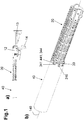
Fig. 1a eine erfindungsgemäß ausgestattete Waffe in Seitenansicht, - die
Fig. 1b ein Zubehörteil an einer Ummantelung in perspektivischer Ansicht, - die
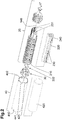
Fig. 2 die Teile derFig. 1a in Explosionsdarstellung, - die
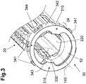
Fig. 3 ein Detail in vergrößertem Maßstab, - die
Fig. 4 einen Adapter in perspektivischer Explosionsdarstellung, - die
Figs. 5a,b Schnitte durch die Laufachse im Montagebereich in unterschiedlichem Maßstab und - die
Figs. 6a,b Schnitte normal zur Laufachse entlang der Linie VI-VI in unterschiedlicher Verriegelungsposition.
- the
Fig. 1a a weapon equipped according to the invention in side view, - the
Figure 1b an accessory on a casing in a perspective view, - the
Fig. 2 the parts of theFig. 1a in exploded view, - the
Fig. 3 a detail on an enlarged scale, - the
Fig. 4 an adapter in a perspective exploded view, - the
Figs. 5a, b Sections through the barrel axis in the assembly area in different scales and - the
Figs. 6a, b Sections normal to the barrel axis along the line VI-VI in different locking positions.
Die
Das gewählte Darstellungsbeispiel des Zubehörteils 40 orientiert sich an einer Abschirmung eines Schalldämpfers und ist bewusst sehr vereinfacht abgebildet. Die Übertragung der erfindungsgemäßen Kopplung eines Zubehörteils 40, wie etwa Lampen, Visiereinrichtungen, oder anderen Accessoires kann im Lichte der Offenbarung mutatis mutandis vom Fachmann vorgenommen werden. Aus diesem Grund ist das Zubehörteil 40 ohne eventuelle weitere Gestaltungsmerkmale als einfacher Zylinder dargestellt, nur im Bereich der Montage sind die notwendigen Details angegeben. Dies schuldet sich der Tatsache, dass außer diesen für die Befestigung relevanten Merkmalen die Ausgestaltung des Zubehörs 40 nicht wesentlich für die Erfindung ist.The selected example of the illustration of the
In
Weiters ist in
Überdies kann in
Das Zubehör 40 weist mehrere L-förmige Bajonettausnehmungen 430 die vom waffenzuwandten Rand des Zubehörs 40 ausgehen, auf. Die Bajonettausnehmungen 430 können grundsätzlich auch bogenförmig ausgebildet sein. Diese Ausführungsform ist nicht dargestellt, wobei der Fachmann einfach nachvollziehen kann, dass durch eine bogenförmige Ausbildung durch die Verdrehbewegung des Zubehörteils 40 eine Verspannung in Richtung des Adapters 30 vorgenommen werden kann.The
In der bevorzugten Ausbildung weist die zumindest eine Bajonettnut 430 eine L-Form mit einem ersten Schenkel, welcher sich vom Rand des waffenseitigen Endes ausgehend parallel zur Laufachse 140 erstreckt, und einem zweiten Schenkel, welcher an diesen anschließend in Umfangsrichtung verlaufend ausgebildet ist, auf.In the preferred embodiment, the at least one bayonet groove 430 has an L-shape with a first leg, which extends from the edge of the weapon-side end parallel to the
In
Zusätzlich zum eben genannten Handguard 210 bzw. der Ummantelung 20 ist in
Ferner sind in
In einer bevorzugten Ausführungsform weist der Handguard 210 von außen betrachtet ein "Rechtsgewinde" auf und die Schrauben 332 sind als eine Art Senkkopfschrauben mit einer Werkzeugaufnahme, z.B. Innensechskant oder Torx, im Schaft ausgebildet. Auf diese Weise können die Schrauben 332 von innen den Adapter 30 in Radialrichtung im Bereich des Hinterabschnitts 32 nach außen durchdringend am Handguard 210 verschraubt werden, indem ein Schraubenzieher von außen nach "links" bewegt wird und somit den Adapter 30 im Bereich seiner Auflagefläche 333 nach "außen" an den Handguard 210 zieht. Diese Methode der "verkehrten Schrauben" bietet den Vorteil, dass keine Schraubenköpfe außen liegen und die Außenkontur des Handguards 210 unbeeinflusst bleibt. Zudem ist dies eine relativ verlustsichere Anbringung der Schrauben.In a preferred embodiment, the
Wie aus
Die
Die radialen Abmessungen 323, 343 können auch ungefähr gleich sein, oder in Sonderfällen sogar der hintere Radialabstand 323 zur Auflagefläche 333 geringer sein als der vordere Radialabstand 343 zur Koppelfläche 342. Dem Fachmann bleibt es aufgrund der Form von Handguard 210 und Zubehör 40 überlassen, eine optimale Abstimmung der Abmessungen in Kenntnis der vorliegenden Erfindung vorzunehmen.The
In den gezeigten Beispielen ist die bevorzugte, gestufte Ausbildung des Adapters 30 gezeigt, wobei im Vorderabschnitt 34 der Abstand in Radialrichtung 343 zur Koppelfläche 342 größer als im Hinterabschnitt 32 ausgebildet ist. Dies wird sehr gut in der Zusammenschau mit
Im Allgemeinen weist die Koppelfläche 342 die Form von Abschnitten von Mantelflächen zumindest eines Kreiszylinders mit der Laufachse 140 als Kreismittelpunkt auf und steht, bei montiertem Zubehör 40, mit zumindest einer, als Gegenkoppelfläche 442 ausgebildeten, Innenfläche des Zubehörs 40 in flächigem Kontakt. Flächig anliegen bzw. flächiger Kontakt sind dabei technisch und nicht mathematisch zu sehen und zu verstehen.In general, the
Das Zubehörteil 40 und der Adapter 30 weisen im Bereich der Koppel- bzw. Gegenkoppelflächen 342, 442 einen an sich bekannten Bajonettverschluss auf, wie insbesondere die
Besonders bevorzugt ist ferner die Anordnung zumindest zweier Adapteröffnungen 344, welche jeweils in einem Winkel von zumindest 15° zu einer gedachten in Vertikalrichtung nach oben, ausgebildet sind. Es können auch mehrere Adapteröffnungen 344, insbesondere unterseitig zur besseren Luftzufuhr, über den Umfang ausgebildet sein, wobei jedoch der obere Bereich - bei waagrecht gehaltener Feuerwaffe - nicht von einer Adapteröffnung 344 durchdrungen sein sollte. Diese Anordnung der Adapteröffnungen 344 sind dazu geeignet den sog. "Mirage-Effekt", also die Verwirbelungen heiß gewordener Luft welche beim Durchblicken einer Visiereinrichtung nachteilig sein kann, zu minimieren.The arrangement of at least two
Die Fixierung der Montage erfolgt bevorzugt, wie dargestellt, mittels zumindest eines, bevorzugt zweier, federbelasteter Druckknöpfe 310. Diese sind mittels zumindest einer Feder 311 in Radialrichtung nach außen vorgespannt und können in Arretierlöcher 425 im Zubehör 40 einrasten, wenn die Bajonettverriegelung durch Eingreifen und Verdrehen der Bajonettfortsätze 341 in die Bajonettnuten 441 abgeschlossen ist. Durch händisches Eindrücken der Druckknöpfe 310 wird die Verriegelung gelöst und das Zubehör 40 kann durch Verdrehen und Abziehen von der Ummantelung 20, respektive dem Adapter 30, einfach abgenommen werden.The assembly is preferably fixed, as shown, by means of at least one, preferably two, spring-loaded
Wie aus
Die Befestigung des Adapters 30 an der Ummantelung 20 erfolgt entsprechend der Vorgabe durch die bestehende Ummantelung, jedenfalls aber bevorzugt im Eingriffsbereich der Auflagefläche(n) 333 mittels Schrauben 332. Diese durchsetzen die Schraublöcher 331, wie zuvor unter Bezugnahme der Beschreibung von
Auf diese erfindungsgemäße Weise werden die Probleme des Standes der Technik gelöst, weil alle Kräfte und Momente, die auf das Zubehör 40 wirken, bzw. durch das Zubehör 40 auftreten (Massekräfte), nicht auf den Lauf 10, sondern direkt auf die Ummantelung 20 ("Handguard assembly") übertragen werden.In this way according to the invention, the problems of the prior art are solved because all forces and moments that act on the
Ein weiterer, sehr positiver Effekt dieser erfindungsgemäßen Montage wird in Zusammenschau der
In
Zudem kann durch die im Wesentlichen rohrförmige Bauweise des Adapters, wie in Zusammenschau der
Die angegebene Luftzufuhr kann wie zuvor erläutert um die Funktion der eventuell vorhandenen, und optimiert angeordneten, Adapteröffnungen 344 ergänzt werden.In addition, due to the essentially tubular design of the adapter, as seen in summary
As explained above, the specified air supply can be supplemented by the function of the
Die
Unter Einbezug der vorangegangenen Erläuterungen, insbesondere der
Die Erfindung ist nicht auf das dargestellte und beschriebene Ausführungsbeispiel beschränkt, sondern kann verschiedentlich adaptiert und ausgestaltet werden. Insbesondere betrifft sie nicht nur ein erfindungsgemäß ausgebildetes Zubehörteil 40, sondern auch den Adapter 30 an sich und auch eine mit einem solchen Adapter versehene Waffe.The invention is not limited to the illustrated and described exemplary embodiment, but can be adapted and configured in various ways. In particular, it relates not only to an accessory 40 designed according to the invention, but also to the
Im Rahmen der Erfindung liegen somit neben dem erfindungsgemäß ausgebildeten Adapter 30 auch entsprechend zu einem derartig ausgebildeten Adapter 30 passende Zubehörteile 40.Within the scope of the invention, in addition to the
Schließlich kann bei "neuen" Waffen der waffenseitige Teil des Adapters 30 ein Teil des Handguards 210 sein, sodass diese den mit größerem Radius versehenen Teil des Adapters 30 samt Bajonettverschluss an ihrem vorderen Ende integral ausgebildet hat. Vereinfacht gesprochen ist kann der Adapter 30 als separates Bauteil entfallen, genauer gesagt der Hinterabschnitt 32 entfällt, und der Vorderabschnitt 34 des Adapters 30 ist integral am Handguard 210 ausgebildet.Finally, in the case of "new" weapons, the weapon-side part of the
Wie zuvor erläutert können auf die erfindungsgemäße Weise sowohl die mechanische Stabilität der Anbindung eines Zubehörteils an die Waffe, die Präzision der Waffe, wie auch die Wärmeabfuhr an Lauf und/oder einem Mündungsaufsatz verbessert werden, und trotzdem eine Verringerung der thermischen Signatur erzielt werden.As explained above, both the mechanical stability of the connection of an accessory to the weapon, the precision of the weapon, as well as the heat dissipation at the barrel and / or a muzzle attachment can be improved in the manner according to the invention, and a reduction in the thermal signature can still be achieved.
In der Beschreibung und den Ansprüchen werden die Begriffe "vorne", "hinten", "oben", "unten" und so weiter in der landläufigen Form und unter Bezugnahme auf den Gegenstand in seiner üblichen Gebrauchslage, gebraucht. Das heißt, dass bei einer Waffe die Mündung des Laufes "vorne" ist, dass der Verschluss bzw. Schlitten durch die Explosionsgase nach "hinten" bewegt wird, etc..In the description and the claims, the terms "front", "rear", "top", "bottom" and so on are used in their usual form and with reference to the object in its usual position of use. This means that in a weapon the muzzle of the barrel is "in front", that the bolt or slide is moved "backwards" by the explosion gases, etc ..
Es soll noch darauf hingewiesen werden, dass in der Beschreibung und den Ansprüchen Angaben wie "unterer Bereich" eines eines Gegenstandes, die untere Hälfte und insbesondere das untere Viertel der Gesamthöhe bedeutet, "unterster Bereich" das unterste Viertel und insbesondere einen noch kleineren Teil; während "mittlerer Bereich" das mittlere Drittel der Gesamthöhe (Breite - Länge) meint. All diese Angaben haben ihre landläufige Bedeutung, angewandt auf die bestimmungsgemäße Position des betrachteten Gegenstandes.It should also be pointed out that in the description and the claims, statements such as "lower area" of an object, the lower half and in particular the lower quarter of the total height means, "lowest area" the lowest quarter and in particular an even smaller part; while "middle area" means the middle third of the total height (width - length). All of this information has its common meaning, applied to the intended position of the object in question.
In der Beschreibung und den Ansprüchen bedeutet "im Wesentlichen" eine Abweichung von bis zu 10 % des angegebenen Wertes, wenn es physikalisch möglich ist, sowohl nach unten als auch nach oben, ansonsten nur in die sinnvolle Richtung, bei Gradangaben (Winkel und Temperatur) sind damit ± 10° gemeint.In the description and the claims, "essentially" means a deviation of up to 10% of the specified value, if it is physically possible, both downwards and upwards, otherwise only in the meaningful direction, for degrees (angle and temperature) this means ± 10 °.
Der Begriff: "Kombination" bzw. "Kombinationen" steht, soferne nichts anderes angegeben, für alle Arten von Kombinationen, ausgehend von zwei der betreffenden Bestandteile bis zu einer Vielzahl oder aller derartiger Bestandteile, der Begriff: "enthaltend" steht auch für "bestehend aus".Unless otherwise stated, the term: “combination” or “combinations” stands for all types of combinations, starting from two of the constituents in question up to a large number or all of such constituents, the term: “containing” also stands for “consisting out".
Die in den einzelnen Ausgestaltungen und Beispielen angegebenen Merkmale und Varianten können mit denen der anderen Beispiele und Ausgestaltungen frei, das heißt ohne die anderen Merkmale des jeweiligen Beispiels, kombiniert und insbesondere zur Kennzeichnung der Erfindung in den Ansprüchen ohne zwangläufige Mitnahme der anderen Merkmale/Details der jeweiligen Ausgestaltung bzw. des jeweiligen Beispiels verwendet werden
Claims (17)
Priority Applications (8)
| Application Number | Priority Date | Filing Date | Title |
|---|---|---|---|
| EP19215974.7A EP3835706B1 (en) | 2019-12-13 | 2019-12-13 | Adapter for mounting an accessory to a firearm |
| EP19216891.2A EP3835708B1 (en) | 2019-12-13 | 2019-12-17 | Front shaft for clamping on an existing weapon |
| IL293577A IL293577A (en) | 2019-12-13 | 2020-11-23 | Handguard for clamping mounting on an existing firearm |
| PCT/EP2020/083075 WO2021121877A1 (en) | 2019-12-13 | 2020-11-23 | Handguard for clamping mounting on an existing firearm |
| BR112022011131A BR112022011131A2 (en) | 2019-12-13 | 2020-11-23 | HAND PROTECTOR FOR FIXING THE ASSEMBLY OF AN EXISTING FIREGUN |
| US17/757,291 US11892260B2 (en) | 2019-12-13 | 2020-11-23 | Handguard for clamping mounting on an existing firearm |
| CA3163898A CA3163898A1 (en) | 2019-12-13 | 2020-11-23 | Handguard for clamping mounting on an existing firearm |
| US17/120,695 US11391532B2 (en) | 2019-12-13 | 2020-12-14 | Adapter for mounting an accessory on a firearm |
Applications Claiming Priority (1)
| Application Number | Priority Date | Filing Date | Title |
|---|---|---|---|
| EP19215974.7A EP3835706B1 (en) | 2019-12-13 | 2019-12-13 | Adapter for mounting an accessory to a firearm |
Publications (3)
| Publication Number | Publication Date |
|---|---|
| EP3835706A1 true EP3835706A1 (en) | 2021-06-16 |
| EP3835706C0 EP3835706C0 (en) | 2023-10-18 |
| EP3835706B1 EP3835706B1 (en) | 2023-10-18 |
Family
ID=68916369
Family Applications (2)
| Application Number | Title | Priority Date | Filing Date |
|---|---|---|---|
| EP19215974.7A Active EP3835706B1 (en) | 2019-12-13 | 2019-12-13 | Adapter for mounting an accessory to a firearm |
| EP19216891.2A Active EP3835708B1 (en) | 2019-12-13 | 2019-12-17 | Front shaft for clamping on an existing weapon |
Family Applications After (1)
| Application Number | Title | Priority Date | Filing Date |
|---|---|---|---|
| EP19216891.2A Active EP3835708B1 (en) | 2019-12-13 | 2019-12-17 | Front shaft for clamping on an existing weapon |
Country Status (6)
| Country | Link |
|---|---|
| US (2) | US11892260B2 (en) |
| EP (2) | EP3835706B1 (en) |
| BR (1) | BR112022011131A2 (en) |
| CA (1) | CA3163898A1 (en) |
| IL (1) | IL293577A (en) |
| WO (1) | WO2021121877A1 (en) |
Families Citing this family (7)
| Publication number | Priority date | Publication date | Assignee | Title |
|---|---|---|---|---|
| USD1015475S1 (en) * | 2019-12-05 | 2024-02-20 | Glock Technology Gmbh | Firearm upper receiver |
| USD1023214S1 (en) * | 2020-06-23 | 2024-04-16 | Bravo Company Mfg, Inc. | Firearm upper receiver |
| US20220196364A1 (en) * | 2020-12-17 | 2022-06-23 | James Matthew Underwood | Handguard |
| US20220252374A1 (en) * | 2021-02-11 | 2022-08-11 | Jason Louthan | Modular handguard for firearm |
| US20220282951A1 (en) * | 2021-03-04 | 2022-09-08 | Bowden Tactical, LLC | Interchangeable handguard system |
| US11725904B2 (en) * | 2021-11-23 | 2023-08-15 | Strike IP, LLC | Firearm handguard with bridge adapter |
| EP4194795A1 (en) | 2021-12-10 | 2023-06-14 | Glock Technology GmbH | Device for forming a secondary attachment of a front shaft |
Citations (4)
| Publication number | Priority date | Publication date | Assignee | Title |
|---|---|---|---|---|
| WO2009139803A2 (en) * | 2008-02-21 | 2009-11-19 | George Koumbis | Assembly and noise suppressor for firearms |
| US20130133976A1 (en) * | 2011-11-29 | 2013-05-30 | A-Tec Holding As | Silencer for a firearm |
| US9658010B1 (en) * | 2014-10-13 | 2017-05-23 | Paul Oglesby | Heat shielding and thermal venting system |
| US20190072354A1 (en) * | 2017-04-27 | 2019-03-07 | Darryl S. Lee | Firearm Suppressor Adapter for Firearm Rails |
Family Cites Families (30)
| Publication number | Priority date | Publication date | Assignee | Title |
|---|---|---|---|---|
| US968583A (en) * | 1909-08-12 | 1910-08-30 | Onesime E Michaud | Attachment for shotguns. |
| US985308A (en) * | 1911-01-09 | 1911-02-28 | Jesse Owen Van Voorhis | Firearm. |
| US2880435A (en) * | 1955-01-18 | 1959-04-07 | Herman T Hale | Pipe cleaning apparatus |
| US4887929A (en) * | 1988-04-25 | 1989-12-19 | Electric Eel Manufacturing Co., Inc. | Cable coupler |
| US4920679A (en) * | 1988-09-21 | 1990-05-01 | Sarles J Stephen | Firearm with detachable barrel |
| US4893426A (en) * | 1988-10-07 | 1990-01-16 | South Central Research Corp. | Lugged coupling apparatus |
| US5271312A (en) * | 1990-12-14 | 1993-12-21 | Colt's Manufacturing Company Inc. | Locating spring and plunger assembly for a firearm |
| US5433133A (en) * | 1994-03-07 | 1995-07-18 | La France; Timothy F. | Quick detachable gun barrel coupling member |
| US5559302A (en) * | 1995-08-31 | 1996-09-24 | Gsl Technology, Inc. | Bayonet type coupling for firearms |
| US6873185B2 (en) | 2002-06-19 | 2005-03-29 | Viasic, Inc. | Logic array devices having complex macro-cell architecture and methods facilitating use of same |
| KR100686794B1 (en) | 2005-01-25 | 2007-02-23 | 삼성에스디아이 주식회사 | Battery monitoring system and its method |
| US7523580B1 (en) * | 2005-11-07 | 2009-04-28 | Jerome Benedict Tankersley | Handguard system integrated to a firearm |
| US7516690B2 (en) * | 2006-12-22 | 2009-04-14 | Mcclellan W Thomas | Firearm suppressor, mounting system and mounting method |
| US9021673B2 (en) * | 2011-02-26 | 2015-05-05 | Steven Ray | Snake glove |
| CZ2011445A3 (en) * | 2011-07-21 | 2012-09-19 | Proarms Armory S. R. O. | Arrangement for exchange and securing barrel of a long firearm |
| US8819980B2 (en) | 2012-11-12 | 2014-09-02 | WHG Properties, LLC | Modular rifle handguard |
| US9175919B2 (en) * | 2013-08-16 | 2015-11-03 | Travis Russell | System and method for attaching a sound suppressor to a firearm |
| US8931196B1 (en) * | 2013-11-18 | 2015-01-13 | Mark C. LaRue | Firearm having capability for field assembly and disassembly |
| US20150377584A1 (en) * | 2014-06-25 | 2015-12-31 | Ati Ip, Llc | Forend-mounted heatshield arrangement for firearms |
| US10107582B2 (en) * | 2015-12-04 | 2018-10-23 | Scott Gray | Quick connect rifle receiver adapter system |
| US9513078B1 (en) * | 2016-05-17 | 2016-12-06 | Precision Tooling Products, LLC | Quick mount firearm barrel accessory |
| US10641573B2 (en) * | 2017-02-27 | 2020-05-05 | Strike Industries, Inc. | Lock mechanism for muzzle shroud and blast diffuser using the same |
| US11047640B1 (en) * | 2017-11-21 | 2021-06-29 | Stwip Llc | Device for dampening residual effects from a firearm suppressor |
| US10480897B2 (en) * | 2017-11-29 | 2019-11-19 | Occam Defense Solutions Inc. | Handguard system for firearms |
| US10352650B2 (en) * | 2017-12-01 | 2019-07-16 | Spec Arms LLC | Firearm handguard securement system and related method |
| US10801798B2 (en) * | 2017-12-29 | 2020-10-13 | Super Dave Designs, LLC | Barrel mounting system |
| US11187474B2 (en) * | 2018-01-09 | 2021-11-30 | William E. Masters | Compact shotgun, multipurpose mount, and trigger assembly |
| US10436549B1 (en) * | 2018-10-02 | 2019-10-08 | 5th Axis, Inc. | Rifle handguard system |
| US10775129B1 (en) * | 2019-09-20 | 2020-09-15 | Bravo Company Mfg, Inc. | Handguard mount with tie bar |
| US11408702B2 (en) * | 2020-06-16 | 2022-08-09 | Austin Reis-Green | Firearm muzzle accessory coupling device, system and method |
-
2019
- 2019-12-13 EP EP19215974.7A patent/EP3835706B1/en active Active
- 2019-12-17 EP EP19216891.2A patent/EP3835708B1/en active Active
-
2020
- 2020-11-23 WO PCT/EP2020/083075 patent/WO2021121877A1/en active Application Filing
- 2020-11-23 BR BR112022011131A patent/BR112022011131A2/en unknown
- 2020-11-23 US US17/757,291 patent/US11892260B2/en active Active
- 2020-11-23 IL IL293577A patent/IL293577A/en unknown
- 2020-11-23 CA CA3163898A patent/CA3163898A1/en active Pending
- 2020-12-14 US US17/120,695 patent/US11391532B2/en active Active
Patent Citations (4)
| Publication number | Priority date | Publication date | Assignee | Title |
|---|---|---|---|---|
| WO2009139803A2 (en) * | 2008-02-21 | 2009-11-19 | George Koumbis | Assembly and noise suppressor for firearms |
| US20130133976A1 (en) * | 2011-11-29 | 2013-05-30 | A-Tec Holding As | Silencer for a firearm |
| US9658010B1 (en) * | 2014-10-13 | 2017-05-23 | Paul Oglesby | Heat shielding and thermal venting system |
| US20190072354A1 (en) * | 2017-04-27 | 2019-03-07 | Darryl S. Lee | Firearm Suppressor Adapter for Firearm Rails |
Also Published As
| Publication number | Publication date |
|---|---|
| EP3835708A1 (en) | 2021-06-16 |
| EP3835706C0 (en) | 2023-10-18 |
| CA3163898A1 (en) | 2021-06-24 |
| BR112022011131A2 (en) | 2022-08-23 |
| US20230020437A1 (en) | 2023-01-19 |
| EP3835708B1 (en) | 2023-12-06 |
| US20210180903A1 (en) | 2021-06-17 |
| IL293577A (en) | 2022-08-01 |
| US11391532B2 (en) | 2022-07-19 |
| WO2021121877A1 (en) | 2021-06-24 |
| EP3835708C0 (en) | 2023-12-06 |
| EP3835706B1 (en) | 2023-10-18 |
| US11892260B2 (en) | 2024-02-06 |
Similar Documents
| Publication | Publication Date | Title |
|---|---|---|
| EP3835706B1 (en) | Adapter for mounting an accessory to a firearm | |
| EP1924815B1 (en) | Gas cylinder block and handgun | |
| DE102011013575B4 (en) | Device for attaching an attachment to a firearm | |
| EP2339287B1 (en) | Clamping system for accessories on a Picatinny rail | |
| DE3522027C2 (en) | ||
| DE102007063610A1 (en) | visor element | |
| DE102004006364A1 (en) | Firearm, in particular self-loading small-caliber rifle | |
| EP1975541A2 (en) | Butt for a repeating rifle and receiver of such a rifle for such a butt | |
| DE2402445A1 (en) | DEVICE FOR SWIVELING SIDE EJECTOR FOR WEAPONS | |
| EP4038337B1 (en) | Barrel unit for a firearm | |
| DE202011102875U1 (en) | Tilting mounting with additional stop | |
| DE102015013803A1 (en) | Adapter for attaching at least one accessory to a self-loading firearm and equipped with this self-loading firearm | |
| EP1864073B1 (en) | Fastening system for fixing a component to a small arm and small arm comprising such a system | |
| WO2008014986A1 (en) | Hinge assembly for a weapon, a visor assembly, and weapon | |
| EP3892954B1 (en) | Fastening device for weapon accessory | |
| EP3835705A1 (en) | Bolt catch for a firearm | |
| EP2660553A2 (en) | Mounting device for the detachable fixing an aiming device to a handgun | |
| DE102005037884B3 (en) | Adapter component for firearm has clamping element acting on it which is elastically deformed when adapter component is adjusted | |
| AT398841B (en) | DEVICE FOR DETACHABLE ASSEMBLY OF A GRENADE LAUNCHER ON AN AUTOMATIC RIFLE | |
| DE2426571A1 (en) | SIGHTING DEVICES FOR FIRE ARMS | |
| EP4038332B1 (en) | Breech for a firearm | |
| DE102007005142B4 (en) | connector | |
| EP4027099B1 (en) | Fire selection unit for a firearm | |
| DE102020126023A1 (en) | silencer | |
| DE102016113983A1 (en) | silencer |
Legal Events
| Date | Code | Title | Description |
|---|---|---|---|
| PUAI | Public reference made under article 153(3) epc to a published international application that has entered the european phase |
Free format text: ORIGINAL CODE: 0009012 |
|
| STAA | Information on the status of an ep patent application or granted ep patent |
Free format text: STATUS: REQUEST FOR EXAMINATION WAS MADE |
|
| 17P | Request for examination filed |
Effective date: 20210330 |
|
| AK | Designated contracting states |
Kind code of ref document: A1 Designated state(s): AL AT BE BG CH CY CZ DE DK EE ES FI FR GB GR HR HU IE IS IT LI LT LU LV MC MK MT NL NO PL PT RO RS SE SI SK SM TR |
|
| STAA | Information on the status of an ep patent application or granted ep patent |
Free format text: STATUS: EXAMINATION IS IN PROGRESS |
|
| 17Q | First examination report despatched |
Effective date: 20230221 |
|
| GRAP | Despatch of communication of intention to grant a patent |
Free format text: ORIGINAL CODE: EPIDOSNIGR1 |
|
| STAA | Information on the status of an ep patent application or granted ep patent |
Free format text: STATUS: GRANT OF PATENT IS INTENDED |
|
| INTG | Intention to grant announced |
Effective date: 20230809 |
|
| GRAS | Grant fee paid |
Free format text: ORIGINAL CODE: EPIDOSNIGR3 |
|
| GRAA | (expected) grant |
Free format text: ORIGINAL CODE: 0009210 |
|
| STAA | Information on the status of an ep patent application or granted ep patent |
Free format text: STATUS: THE PATENT HAS BEEN GRANTED |
|
| AK | Designated contracting states |
Kind code of ref document: B1 Designated state(s): AL AT BE BG CH CY CZ DE DK EE ES FI FR GB GR HR HU IE IS IT LI LT LU LV MC MK MT NL NO PL PT RO RS SE SI SK SM TR |
|
| REG | Reference to a national code |
Ref country code: GB Ref legal event code: FG4D Free format text: NOT ENGLISH |
|
| REG | Reference to a national code |
Ref country code: CH Ref legal event code: EP |
|
| REG | Reference to a national code |
Ref country code: IE Ref legal event code: FG4D Free format text: LANGUAGE OF EP DOCUMENT: GERMAN |
|
| REG | Reference to a national code |
Ref country code: DE Ref legal event code: R096 Ref document number: 502019009690 Country of ref document: DE |
|
| U01 | Request for unitary effect filed |
Effective date: 20231030 |
|
| U07 | Unitary effect registered |
Designated state(s): AT BE BG DE DK EE FI FR IT LT LU LV MT NL PT SE SI Effective date: 20231106 |
|
| U20 | Renewal fee paid [unitary effect] |
Year of fee payment: 5 Effective date: 20231130 |
|
| PGFP | Annual fee paid to national office [announced via postgrant information from national office to epo] |
Ref country code: GB Payment date: 20231204 Year of fee payment: 5 |
|
| PGFP | Annual fee paid to national office [announced via postgrant information from national office to epo] |
Ref country code: CZ Payment date: 20231204 Year of fee payment: 5 |
|
| PG25 | Lapsed in a contracting state [announced via postgrant information from national office to epo] |
Ref country code: GR Free format text: LAPSE BECAUSE OF FAILURE TO SUBMIT A TRANSLATION OF THE DESCRIPTION OR TO PAY THE FEE WITHIN THE PRESCRIBED TIME-LIMIT Effective date: 20240119 |
|
| PG25 | Lapsed in a contracting state [announced via postgrant information from national office to epo] |
Ref country code: IS Free format text: LAPSE BECAUSE OF FAILURE TO SUBMIT A TRANSLATION OF THE DESCRIPTION OR TO PAY THE FEE WITHIN THE PRESCRIBED TIME-LIMIT Effective date: 20240218 |