EP3833508B1 - Kühlmittelwiederaufnahme und -rückführung in materialabtragungssystemen - Google Patents
Kühlmittelwiederaufnahme und -rückführung in materialabtragungssystemen Download PDFInfo
- Publication number
- EP3833508B1 EP3833508B1 EP19758558.1A EP19758558A EP3833508B1 EP 3833508 B1 EP3833508 B1 EP 3833508B1 EP 19758558 A EP19758558 A EP 19758558A EP 3833508 B1 EP3833508 B1 EP 3833508B1
- Authority
- EP
- European Patent Office
- Prior art keywords
- recapture
- recirculation
- reservoir
- material removal
- cabinet
- Prior art date
- Legal status (The legal status is an assumption and is not a legal conclusion. Google has not performed a legal analysis and makes no representation as to the accuracy of the status listed.)
- Active
Links
Images




Classifications
-
- B—PERFORMING OPERATIONS; TRANSPORTING
- B23—MACHINE TOOLS; METAL-WORKING NOT OTHERWISE PROVIDED FOR
- B23Q—DETAILS, COMPONENTS, OR ACCESSORIES FOR MACHINE TOOLS, e.g. ARRANGEMENTS FOR COPYING OR CONTROLLING; MACHINE TOOLS IN GENERAL CHARACTERISED BY THE CONSTRUCTION OF PARTICULAR DETAILS OR COMPONENTS; COMBINATIONS OR ASSOCIATIONS OF METAL-WORKING MACHINES, NOT DIRECTED TO A PARTICULAR RESULT
- B23Q11/00—Accessories fitted to machine tools for keeping tools or parts of the machine in good working condition or for cooling work; Safety devices specially combined with or arranged in, or specially adapted for use in connection with, machine tools
- B23Q11/0003—Arrangements for preventing undesired thermal effects on tools or parts of the machine
-
- B—PERFORMING OPERATIONS; TRANSPORTING
- B23—MACHINE TOOLS; METAL-WORKING NOT OTHERWISE PROVIDED FOR
- B23Q—DETAILS, COMPONENTS, OR ACCESSORIES FOR MACHINE TOOLS, e.g. ARRANGEMENTS FOR COPYING OR CONTROLLING; MACHINE TOOLS IN GENERAL CHARACTERISED BY THE CONSTRUCTION OF PARTICULAR DETAILS OR COMPONENTS; COMBINATIONS OR ASSOCIATIONS OF METAL-WORKING MACHINES, NOT DIRECTED TO A PARTICULAR RESULT
- B23Q11/00—Accessories fitted to machine tools for keeping tools or parts of the machine in good working condition or for cooling work; Safety devices specially combined with or arranged in, or specially adapted for use in connection with, machine tools
- B23Q11/10—Arrangements for cooling or lubricating tools or work
- B23Q11/1069—Filtration systems specially adapted for cutting liquids
-
- B—PERFORMING OPERATIONS; TRANSPORTING
- B01—PHYSICAL OR CHEMICAL PROCESSES OR APPARATUS IN GENERAL
- B01D—SEPARATION
- B01D29/00—Filters with filtering elements stationary during filtration, e.g. pressure or suction filters, not covered by groups B01D24/00 - B01D27/00; Filtering elements therefor
- B01D29/01—Filters with filtering elements stationary during filtration, e.g. pressure or suction filters, not covered by groups B01D24/00 - B01D27/00; Filtering elements therefor with flat filtering elements
- B01D29/03—Filters with filtering elements stationary during filtration, e.g. pressure or suction filters, not covered by groups B01D24/00 - B01D27/00; Filtering elements therefor with flat filtering elements self-supporting
-
- B—PERFORMING OPERATIONS; TRANSPORTING
- B01—PHYSICAL OR CHEMICAL PROCESSES OR APPARATUS IN GENERAL
- B01D—SEPARATION
- B01D29/00—Filters with filtering elements stationary during filtration, e.g. pressure or suction filters, not covered by groups B01D24/00 - B01D27/00; Filtering elements therefor
- B01D29/62—Regenerating the filter material in the filter
- B01D29/70—Regenerating the filter material in the filter by forces created by movement of the filter element
- B01D29/72—Regenerating the filter material in the filter by forces created by movement of the filter element involving vibrations
-
- B—PERFORMING OPERATIONS; TRANSPORTING
- B01—PHYSICAL OR CHEMICAL PROCESSES OR APPARATUS IN GENERAL
- B01D—SEPARATION
- B01D35/00—Filtering devices having features not specifically covered by groups B01D24/00 - B01D33/00, or for applications not specifically covered by groups B01D24/00 - B01D33/00; Auxiliary devices for filtration; Filter housing constructions
- B01D35/20—Vibrating the filters
-
- B—PERFORMING OPERATIONS; TRANSPORTING
- B23—MACHINE TOOLS; METAL-WORKING NOT OTHERWISE PROVIDED FOR
- B23D—PLANING; SLOTTING; SHEARING; BROACHING; SAWING; FILING; SCRAPING; LIKE OPERATIONS FOR WORKING METAL BY REMOVING MATERIAL, NOT OTHERWISE PROVIDED FOR
- B23D59/00—Accessories specially designed for sawing machines or sawing devices
- B23D59/006—Accessories specially designed for sawing machines or sawing devices for removing or collecting chips
-
- B—PERFORMING OPERATIONS; TRANSPORTING
- B23—MACHINE TOOLS; METAL-WORKING NOT OTHERWISE PROVIDED FOR
- B23D—PLANING; SLOTTING; SHEARING; BROACHING; SAWING; FILING; SCRAPING; LIKE OPERATIONS FOR WORKING METAL BY REMOVING MATERIAL, NOT OTHERWISE PROVIDED FOR
- B23D59/00—Accessories specially designed for sawing machines or sawing devices
- B23D59/02—Devices for lubricating or cooling circular saw blades
- B23D59/025—Devices for lubricating or cooling circular saw blades the lubricating or cooling medium being applied through the mounting means of the tool, e.g. the tool spindle or hub
-
- B—PERFORMING OPERATIONS; TRANSPORTING
- B23—MACHINE TOOLS; METAL-WORKING NOT OTHERWISE PROVIDED FOR
- B23Q—DETAILS, COMPONENTS, OR ACCESSORIES FOR MACHINE TOOLS, e.g. ARRANGEMENTS FOR COPYING OR CONTROLLING; MACHINE TOOLS IN GENERAL CHARACTERISED BY THE CONSTRUCTION OF PARTICULAR DETAILS OR COMPONENTS; COMBINATIONS OR ASSOCIATIONS OF METAL-WORKING MACHINES, NOT DIRECTED TO A PARTICULAR RESULT
- B23Q11/00—Accessories fitted to machine tools for keeping tools or parts of the machine in good working condition or for cooling work; Safety devices specially combined with or arranged in, or specially adapted for use in connection with, machine tools
- B23Q11/10—Arrangements for cooling or lubricating tools or work
-
- B—PERFORMING OPERATIONS; TRANSPORTING
- B23—MACHINE TOOLS; METAL-WORKING NOT OTHERWISE PROVIDED FOR
- B23Q—DETAILS, COMPONENTS, OR ACCESSORIES FOR MACHINE TOOLS, e.g. ARRANGEMENTS FOR COPYING OR CONTROLLING; MACHINE TOOLS IN GENERAL CHARACTERISED BY THE CONSTRUCTION OF PARTICULAR DETAILS OR COMPONENTS; COMBINATIONS OR ASSOCIATIONS OF METAL-WORKING MACHINES, NOT DIRECTED TO A PARTICULAR RESULT
- B23Q11/00—Accessories fitted to machine tools for keeping tools or parts of the machine in good working condition or for cooling work; Safety devices specially combined with or arranged in, or specially adapted for use in connection with, machine tools
- B23Q11/12—Arrangements for cooling or lubricating parts of the machine
- B23Q11/126—Arrangements for cooling or lubricating parts of the machine for cooling only
-
- B—PERFORMING OPERATIONS; TRANSPORTING
- B24—GRINDING; POLISHING
- B24B—MACHINES, DEVICES, OR PROCESSES FOR GRINDING OR POLISHING; DRESSING OR CONDITIONING OF ABRADING SURFACES; FEEDING OF GRINDING, POLISHING, OR LAPPING AGENTS
- B24B55/00—Safety devices for grinding or polishing machines; Accessories fitted to grinding or polishing machines for keeping tools or parts of the machine in good working condition
- B24B55/02—Equipment for cooling the grinding surfaces, e.g. devices for feeding coolant
- B24B55/03—Equipment for cooling the grinding surfaces, e.g. devices for feeding coolant designed as a complete equipment for feeding or clarifying coolant
-
- B—PERFORMING OPERATIONS; TRANSPORTING
- B23—MACHINE TOOLS; METAL-WORKING NOT OTHERWISE PROVIDED FOR
- B23D—PLANING; SLOTTING; SHEARING; BROACHING; SAWING; FILING; SCRAPING; LIKE OPERATIONS FOR WORKING METAL BY REMOVING MATERIAL, NOT OTHERWISE PROVIDED FOR
- B23D59/00—Accessories specially designed for sawing machines or sawing devices
- B23D59/04—Devices for lubricating or cooling straight or strap saw blades
Definitions
- the present disclosure generally relates to fluid filtering and, more particularly, to coolant recapture and/or recirculation in material removal systems.
- WO 2013021410A1 discloses a sludge separation and removal device including a filtration unit in the form of meshes that separate and remove sludge from cutting fluid used in a machine tool.
- the present disclosure is directed to coolant fluid recapture, recirculation, and/or filtering in material removal systems, for example, substantially as illustrated by and/or described in connection with at least one of the figures, and as set forth more completely in the claims.
- the examples described herein are not limited to only the recited values, ranges of values, positions, orientations, and/or actions but rather should include reasonably workable deviations.
- x and/or y means any element of the three-element set ⁇ (x), (y), (x, y) ⁇ . In other words, “x and/or y” means “one or both of x and y”.
- x, y, and/or z means any element of the seven-element set ⁇ (x), (y), (z), (x, y), (x, z), (y, z), (x, y, z) ⁇ . In other words, "x, y and/or z” means “one or more of x, y and z”.
- fluid when used as a noun, refers to a free-flowing deformable substance with no fixed shape, including, inter alia, gas (e.g., air, atmosphere, etc.), liquid (e.g., water, solution, etc), and/or plasma.
- gas e.g., air, atmosphere, etc.
- liquid e.g., water, solution, etc
- plasma e.g., plasma
- Some examples of the present disclosure relate to a material removal system, comprising a material removal cabinet having a cabinet inlet and a cabinet outlet, and a recirculation system in fluid communication with the cabinet inlet and cabinet outlet, the recirculation system, comprising a recirculation tank, and a vibration device configured to vibrate at least a portion of the recirculation system, so as to reduce obstruction of the recirculation system or increase compaction of within the recirculation system.
- the recirculation system further comprises a filtering surface configured to filter fluid within the recirculation system.
- the recirculation tank is in fluid communication with the cabinet inlet, and the recirculation system further comprises a recapture reservoir in fluid communication with the cabinet outlet and the recirculation tank, the filtering surface configured to filter fluid flowing between the recapture reservoir to the recirculation tank.
- the filtering surface has openings sized to prevent passage of debris to the recirculation tank.
- the recapture reservoir is positioned at least partly within the recirculation tank.
- the recapture reservoir further including a removable cover.
- the recapture reservoir comprises a container having a top, a bottom, and a porous sidewall between the top and the bottom.
- Some examples of the present disclosure relate to a recirculation apparatus, comprising a recirculation tank, a recapture reservoir in fluid communication with the recirculation tank, a filtering surface configured to filter fluid communicated between the recapture reservoir and the recirculation tank, the filtering surface comprising openings sized to prohibit passage of particulates between the recapture reservoir and the recirculation tank, and a vibration device configured to vibrate one or more of the recirculation tank, the recapture reservoir, and the filtering surface, so as to reduce obstruction of the filtering surface or increase compaction of filtered particulates.
- the recapture reservoir further includes a removable cover.
- the recapture reservoir comprises a container having a top, a bottom, and a sidewall connected to the bottom, the top comprising the removable cover.
- the recapture reservoir comprises a container having a top, a bottom, and a porous sidewall between the top and the bottom.
- the apparatus further comprises a support connecting the recapture reservoir to the recirculation tank.
- the vibration device is in contact with the support.
- the apparatus further comprises a dampener positioned between the support and the recapture reservoir, the dampener configured to reduce noise created by vibrations communicated between the support and the recapture reservoir.
- Some examples of the present disclosure relate to a method for recirculating coolant, comprising routing a coolant from a material removal cabinet to a recirculation system, vibrating the recirculation system so as to increase compaction of particulates within the recirculation system, and routing the coolant from the recirculation system to the material removal cabinet.
- the recirculation system comprises a recirculation tank in fluid communication with the material removal cabinet.
- the recirculation system further comprises a filtering surface configured to filter fluid flow within the recirculation system, and vibrating the recirculation system further reduces obstruction of the filtering surface.
- the recirculation tank is in fluid communication with an inlet of the material removal cabinet, and the recirculation system further comprises a recapture reservoir in fluid communication with the recirculation tank and an outlet of the material removal cabinet, the filtering surface configured to filter fluid flow between the recapture reservoir and the recirculation tank.
- the material removal cabinet includes a material removal machine configured to remove material from a sample.
- the material removal machine includes a saw, a polisher, or a grinder.
- a recirculation tank recirculates and/or recycles the coolant.
- the recirculation tank is in fluid communication with an inlet and/or outlet of a cabinet (and/or housing or other delivery and/or capture system) of the machine, so as to receive the coolant from the cabinet and/or deliver recycled coolant back to the cabinet.
- the recirculation tank may include a recapture reservoir having a filtering surface configured to prevent debris and/or swarf (such as produced by the machine, for example) from entering the recirculation tank and/or being recirculated with the coolant.
- a vibration device e.g., a vibration motor and/or vibrating actuator
- the positioning, orientation, and/or vibration of the filtering surface may help to keep the filtering surface free from obstruction, so that coolant may continue move through the recapture reservoir to the recirculation tank for recirculation.
- the filtering surface may have relatively small openings, so as to prevent passage of particulates. Whereas more conventional filters with small openings may get clogged easily and/or frequently, necessitating frequent replacement and/or cleaning, the positioning, orientation, and/or vibration of the filtering surface substantially reduces clogging and/or obstruction. Thus, the required frequency of cleaning and/or replacement is reduced. Additionally, the vibration helps to settle and/or compact filtered particulates to the bottom of the recapture reservoir (and/or recirculation tank) where the particulates may be more easily removed.
- FIG. 1 shows an example material removal system 100.
- the material removal system 100 includes a material removal machine 102 enclosed in a cabinet 104 and a recirculation tank 200 in fluid communication with the cabinet 104.
- the cabinet 104 is approximately cubical, though, in some examples, the cabinet 104 may take a variety of other shapes.
- the material removal machine 102 includes a material removal instrument 108, such as a saw blade, abrasive saw, grinder, polisher, and/or some other material removal instrument, for example.
- the material removal instrument 108 is secured to a support assembly 110 within the cabinet 104.
- the material removal instrument 108 is also partially encased within a shield 112. As shown, the shield 112 is attached to a cooling system.
- the cooling system includes several coolant hoses 114 attached to the shield 112 through a manifold 116. Each hose 114 terminates in a nozzle 118.
- the nozzles 118 are configured to spray (and/or otherwise provide) coolant into the cabinet 104.
- the nozzles 118 may introduce coolant to the machine 102, a sample and/or workpiece (not shown), a table (not shown), and/or other components of the material removal system 100.
- the hoses 114 are configured to receive coolant from a hose inlet 120 that is also attached to the manifold 116.
- the hose inlet 120 is in fluid communication with a cabinet inlet 122 through a coolant tube 124.
- the coolant tube 124 is configured to route coolant from the cabinet inlet 122, through the coolant tube 124 to the hose inlet 120.
- the hoses 114 are configured to route the coolant to their respective nozzles 118 and spray the coolant into the cabinet 104.
- the coolant introduced by the nozzles 118 may serve to cool and/or clean the material removal machine 102 and/or other components of the material removal system 100, while also removing debris and/or swarf from the cabinet 104.
- the hose inlet 120 may not be attached to the manifold 116. In some examples, there may be more than one manifold 116, hose inlet 120, tube 124, and/or cabinet inlet 122. In some examples, there may be more or less than two hoses 114 and/or nozzles 118. In some examples, one or more fluid actuators (e.g., pumps) may be used to propel the coolant through the tube 124, hose inlet 120, hoses 114, and/or nozzles 118.
- fluid actuators e.g., pumps
- the cabinet 104 further includes a cabinet outlet 126 (and/or drain).
- the cabinet outlet 126 comprises a porous sieve (and/or mesh, filter, screen, etc.) configured to allow coolant to pass while prohibiting larger particulate matter (e.g., dislodged, freed, and/or unattached components of the material removal machine 102) from passing.
- the cabinet outlet 126 may omit the sieve, and may simply comprise an opening.
- the cabinet outlet 126 is in fluid communication with a drain pipe 128 that leads to a coolant recirculation tank 200.
- drain pipe 128 is shown as being straight, in some examples the drain pipe 128 may be curved and/or include one or more appropriate drain pipe devices, such as a P-trap, for example. In the example of FIG. 1 , the drain pipe 128 leads to a recapture inlet 302 of the recirculation tank 200.
- the recapture inlet 302 is simply a hole.
- the recapture inlet 302 includes a porous sieve (and/or mesh, filter, screen, etc.) configured to allow coolant to pass while prohibiting some particulate matter (e.g., debris, swarf, etc.) from passing.
- the recapture inlet 302 is formed in a removable cover 304 of a recapture reservoir 300 of the recirculation tank 200.
- the recapture inlet 302 may instead be formed in a sidewall 306 of the recapture reservoir 300 and/or in some other part of the recirculation tank 200.
- the recirculation tank 200 is positioned below the cabinet 104, such that the force of gravity may be sufficient to propel the coolant through the drain pipe 128 to the recirculation tank 200 and/or recapture reservoir 300.
- the recirculation tank 200 and/or recapture reservoir 300 may instead be positioned above and/or to the side of the cabinet 104, and/or some other force (e.g. a pump) may propel the coolant through the drain pipe 128 from the cabinet 104 to the recirculation tank 200.
- the recirculation tank 200 further includes a pump 202 configured to propel recaptured coolant from the recirculation tank 200 through a conduit 130 to the cabinet inlet 122 of the cabinet 104.
- FIG. 2 shows an enlarged view of the recirculation tank 200.
- the recirculation tank 200 is approximately cubical. In some examples, the recirculation tank 200 may take on a variety of different shapes and sizes.
- the recirculation tank 200 includes a bottom wall 204 and several sidewalls 206 connected to the bottom wall 204. The bottom wall 204 and sidewalls 206 enclose a hollow interior 208 that serves as a repository for coolant before the coolant is recirculated to the cabinet 104.
- FIGS. 1 shows an enlarged view of the recirculation tank 200.
- the recirculation tank 200 is approximately cubical. In some examples, the recirculation tank 200 may take on a variety of different shapes and sizes.
- the recirculation tank 200 includes a bottom wall 204 and several sidewalls 206 connected to the bottom wall 204.
- the bottom wall 204 and sidewalls 206 enclose a hollow interior 208 that serves as a repository for coolant before the coolant is
- the recirculation tank 200 has an open top, through which the conduit 130 extends to bring the recirculation tank 200 in fluid communication with the cabinet inlet 122.
- the recirculation tank 200 may have a closed top, and/or the conduit 130 may extend through the bottom wall 204 and/or one of the sidewalls 206.
- the recirculation tank 200 includes and/or substantially encloses a recapture reservoir 300.
- the recapture reservoir 300 may be separate from the recirculation tank 200, such as positioned next to, above, and/or below the recirculation tank 200. As shown, the recapture reservoir 300 is approximately cubical, though it will be understood that in some examples the recapture reservoir 300 may take on a variety of different shapes and sizes.
- the recapture reservoir 300 is in fluid communication with the cabinet 104 through the recapture inlet 302 and/or drain pipe 128. The recapture reservoir 300 is also in fluid communication with the recirculation tank 200 through a filtering surface 308 of the recapture reservoir 300.
- the recapture reservoir 300 is suspended within the substantially larger recirculation tank 200. More particularly, the recapture reservoir 300 is elevated above the floor and spaced from sidewalls of the recirculation tank 200 by floor supports 210 and side supports 212.
- the floor supports 210 and/or side supports 212 may be attached to the recirculation tank 200 and/or the recapture reservoir 300.
- the side supports 212 and/or floor supports 210 may comprise brackets, stanchions, stands, and/or other appropriate structures.
- the floor supports 210 and/or side supports 212 may be removably attached to the recapture reservoir 300 (e.g., through sliding rails, snap fit receiving brackets, snap fit recesses, appropriately sized/places recesses, flanges, fasteners etc.), so as to enable easy removal of the recapture reservoir 300 from the recirculation tank 200, such as for cleaning, replacement, etc. While two side supports 212 are shown attached to one sidewall 206 of the recirculation tank 200, in some examples more or fewer side supports 212 may be attached to the recirculation tank 200, and/or that the side supports 212 may be attached to a different sidewall 206 and/or more sidewalls 206. Likewise, in some examples, more or less floor supports 210 than are shown may be used.
- the recapture reservoir 300 comprises an approximately cubical hollow container.
- the recapture reservoir 300 includes a bottom 310, a top removable cover 304, and a plurality of sidewalls 306 connecting the bottom 310 to the top cover 304.
- the bottom 310 and at least some of the sidewalls 306 are integrally connected with one another, such that removal of the bottom 310 and/or sidewalls 306 would be difficult and/or cause a rupture (and/or breakdown, destruction, etc.) of the recapture reservoir 300.
- the top cover 304 is removable from the recapture reservoir 300.
- the top cover 304 and/or recapture reservoir 300 may include features to make securement and/or removal of the top cover 304 easier, such as complementary lips, rims, ledges, joints, pillars, recesses, protrusions, and/or flanges.
- fasteners may be used to secure the top cover 304 to the recapture reservoir 300, and such fasteners may be configured for relatively simple loosening and/or removable in order to allow the top cover 304 to be removed non-destructively.
- the top cover 304 may be entirely omitted.
- the recapture reservoir 300 is in fluid communication with the recirculation tank 200 through a filtering surface 308.
- the filtering surface 308 is a sidewall of the recapture reservoir 300.
- the filtering surface 308 may be a different surface of the recapture reservoir 300.
- the filtering surface 308 may be a removable sidewall (or some other removable surface) of the recapture reservoir 300, such as a sidewall slidably attached (e.g., via rails, tracks, and/or other appropriate mechanisms) to the other sidewalls 310, so as to allow for easy removal (e.g., for cleaning, replacement, etc.).
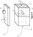
- FIG. 4 shows another recapture reservoir 400 where the filtering surface 308 is distinct and/or spaced from the sidewalls 406, 407.
- the filtering surface 308 may comprise a separate, movable, and/or removable surface (e.g., a wire mesh screen).
- the filtering surface 308 divides the recapture reservoir 400 into two sections. While the sections are depicted as approximately equal in the example of FIG. 4 , in some examples the sections may be different sizes.
- the sidewall 407 of the recapture reservoir 400 includes openings 412 that are significantly larger than the openings 312. In FIG.
- the openings 412 are configured to simply allow fluid flow between the recapture reservoir 400 and the recirculation tank 300, rather than being configured for filtering.
- fluid enters the recapture reservoir 400 in one section (farther from the sidewall 407), flows through the filtering surface 308 to the other section (closer to the sidewall 407) of the recapture reservoir 400, and then flows out of the recapture reservoir 400 through the openings 412.
- the filtering surface 308 includes a plurality of openings 312.
- the openings 312 are sized to allow movement of coolant through the openings 312, while prohibiting movement of particulates (and/or debris, swarf, etc.) through the openings 312.
- the openings 312 may be smaller and/or finer than those in the sieve of the cabinet outlet 126, such that the filtering surface 308 will prohibit passage of particulate matter that the cabinet outlet 126 allowed through. While the openings 312 are depicted in FIGS. 1-6 as somewhat sizable, for the sake of understanding, in actual implementation, the openings 312 may be much smaller. While the openings 312 are depicted as circular in FIGS.
- the openings 312 may be of different shapes.
- the lowermost openings 312 are elevated above the bottom 310 (and/or lower surface) of the recapture reservoir 300 (and/or the bottom wall 604 of the recirculation tank 600), which may allow some space for particulates and/or coolant to build up (and/or be compacted) within the recapture reservoir 300 before encountering the openings 312.
- the openings 312 may be elevated further.
- the elevation may be removed, and the openings 312 may extend all the way to the bottom of the recapture reservoir 300 (and/or recirculation tank 600).
- a vibration device 500 (e.g., a vibration motor) is in contact with the recapture reservoir 300.
- the vibration device is in contact with the removable cover 304 of the recapture reservoir 300.
- the vibration device 500 is contact with and/or attached to a side support 212, which will communicate the vibration to the sidewall 306 of the recapture reservoir 300 (which will communicate the vibration to the filtering surface 308).
- the vibration device 500 may be in direct contact with and/or attached to the sidewall 306, the filtering surface 308, a different sidewall 306, and/or the bottom wall 310 of the recapture reservoir 300, and/or with one or more floor supports 210.
- a dampening barrier e.g. a foam insulation barrier
- a dampening barrier may be placed between the vibration device 500 and the recirculation tank 200 in order to limit the vibrations of the vibrations device 500 from reaching the recirculation tank 200 via the support structures 210, 212 of the recapture reservoir 300.
- a dampening barrier e.g. a foam insulation, rubber, silicone, or other energy dissipating material
- Such isolation and/or decoupling may help to reduce noise generated when vibrations are communicated between surfaces. While the coolant may experience some vibration, the coolant may also damp the vibration and provide vibration insulation between the supports 210, 212, recapture reservoir 300, and/or recirculation tank 200.
- the vibration device 500 may be an electrically powered device.
- the vibration device 500 may receive electrical power from a power source (now shown) of the material removal system 100 and/or material removal machine 102.
- the vibration device 500 may receive electrical power from a local power source (e.g., batteries).
- the vibration device 500 may be a direct current electrical motor having an offset weight attached to a shaft of the motor, such that rotation of the shaft causes rotation of the weight. As the weight is offset from an axis of rotation of the shaft, the weight may produce vibrations (and/or shaking, tremors, oscillations, reverberations, etc.). Vibrations produced by the vibration device 500 may be transferred and/or communicated to the recapture reservoir 300 and/or filtering surface 308. These vibrations may help to dislodge particulates that may otherwise block (and/or obstruct, clog, etc.) the openings 312.
- the vibrations may also help to settle and/or compact particulate matter into a bottom portion of the recapture reservoir 300, which may further improve throughput of the filtering surface 308 and/or make cleaning of the recapture reservoir 300 easier and/or more efficient.
- the vibrations of the vibration device 500 that were intended to help keep the openings 312 of the filtering surface 308 unobstructed
- This settling and/or compacting helps to reduce the amount of particulates floating in the coolant that may attempt to flow through the filtering surface 308, which also reduces clogging.
- coolant may be sprayed from the nozzles 118 of the material removal system 100 in order to cool and/or clean the material removal machine 102 and/or interior of the cabinet 104.
- the coolant may then flow through the cabinet outlet 126, along with some particulate matter that may have been captured and/or washed away by the coolant.
- the sieved cabinet outlet 126 may stop some of the larger particular matter from flowing through the cabinet outlet 126, so as to stop dislodged, loose, and/or freed components of the material removal system 100, for example, from being accidentally washed away.
- the coolant and/or any coolant captured particulate matter that flows through the cabinet outlet 126 may flow through the drain pipe 128 to the recapture reservoir 300 through the inlet 302.
- the coolant may flow through the openings 312 of the filtering surface 308.
- the filtering surface 308 may prohibit particulate matter that attempts to flow through the openings 312.
- the vibration device 500 may impart vibrations to the recapture reservoir 300 and/or filtering surface 308 to dislodge any particulates that become stuck in and/or clog the openings 312, so as to prevent obstruction and ensure continuous flow and/or filtering of coolant through the filtering surface.
- the coolant After passing through the filtering surface 308, the coolant may flow into the recirculation tank 200, where the coolant may be recirculated to the cabinet inlet via the pump 202.
- the coolant may flow to the nozzles 118 via the tube 124, hose inlet 120, and/or hoses 114, and once again be sprayed from the nozzles 118 to repeat the process.
- an operator may wish to clean and/or replace the filtering surface 308 and/or recapture reservoir 300.
- the operator may take off the removable cover 304 and scoop out and/or otherwise remove any particulate matter that has been retained within the recapture reservoir 300.
- some or all of the interior of the recapture reservoir 300 may be lined with a porous material (e.g., having pores sizes similar to those of the openings 312), such that an operator may quickly remove any filtered particulate matter by removing the porous material.
- the filtering surface 308 may comprise such a removable porous material.
- the operator may alternatively (or additionally) remove the filtering surface 308 and/or the entire recapture reservoir 300 for cleaning and/or replacement.
- FIG. 6 shows another example recirculation tank 600.
- the recirculation tank 600 includes no recapture reservoir 300, 400, but still includes a filtering surface 308 and a vibration device 500 in contact with the recirculation tank 600.
- the vibration device 500 is shown in contact with the recirculation tank 600 proximate the bottom wall 604 and/or filtering surface 308, in some examples, the vibration device 500 may be positioned differently.
- the filtering surface 308 divides the recirculation tank 600 into two sections, a section with the pump 202, and a section without the pump 202. While the sections are shown as approximately equal in the example of FIG. 6 , in some examples, the sections may be of different sizes.
- the recirculation tank 600 is positioned such that the section that does not have the pump 202 is in fluid communication with the drain pipe 128.
- fluid will flow into the recirculation tank 600 from the cabinet 106 via the drain pipe 128, through the filtering surface 308, and then back to the cabinet 106 via the pump 202.
- Vibrations from the vibration device 500 will help to keep the filtering surface 308 free from obstruction and increase compaction of filtered particulates within the recirculation tank 600.
Landscapes
- Engineering & Computer Science (AREA)
- Mechanical Engineering (AREA)
- Chemical & Material Sciences (AREA)
- Chemical Kinetics & Catalysis (AREA)
- Grinding-Machine Dressing And Accessory Apparatuses (AREA)
- Filtration Of Liquid (AREA)
- Auxiliary Devices For Machine Tools (AREA)
Claims (15)
- Materialentfernungssystem (100), aufweisend:einen Materialentfernungsschrank (104) für eine Materialentfernungsmaschine, wobei der Schrank (104) einen Schrankeinlass (122) und einen Schrankauslass (126) hat; undein Rezirkulationssystem in Fluidverbindung mit dem Schrankeinlass (122) und dem Schrankauslass (126), das Rezirkulationssystem aufweisend:einen Rezirkulationstank (200), undeine Vibrationsvorrichtung (500), die so konfiguriert ist, dass sie zumindest einen Teil des Rezirkulationssystems vibriert, um die Behinderung des Rezirkulationssystems zu verringern oder die Verdichtung innerhalb des Rezirkulationssystems zu erhöhen.
- Materialentfernungssystem (100) nach Anspruch 1, wobei das Rezirkulationssystem ferner eine Filterfläche (308) aufweist, die konfiguriert ist, um Fluid innerhalb des Rezirkulationssystems zu filtern.
- Materialentfernungssystem (100) nach Anspruch 2, wobei der Rezirkulationstank (200) in Fluidverbindung mit dem Schrankeinlass (122) steht, und wobei das Rezirkulationssystem ferner ein Wiedergewinnungsreservoir (300) in Fluidverbindung mit dem Schrankauslass (126) und dem Rezirkulationstank (200) aufweist, wobei die Filterfläche (308) konfiguriert ist, um Fluid, das zwischen dem Wiedergewinnungsreservoir (300) zu dem Rezirkulationstank (200) fließt, zu filtern.
- Materialentfernungssystem (100) nach Anspruch 3, wobei die Filterfläche (308) Öffnungen (312) hat, die so bemessen sind, dass sie den Durchgang von Schmutz zu dem Rezirkulationstank (200) verhindern.
- Materialentfernungssystem (100) nach Anspruch 3, wobei das Wiedergewinnungsreservoir (300) zumindest teilweise innerhalb des Rezirkulationstanks (200) positioniert ist.
- Materialentfernungssystem (100) nach Anspruch 3, wobei das Wiedergewinnungsreservoir (300) ferner eine entfernbare Abdeckung (304) umfasst.
- Materialentfernungssystem (100) nach Anspruch 3, wobei das Wiedergewinnungsreservoir (300) einen Behälter mit einer Oberseite, einer Unterseite und einer porösen Seitenwand zwischen der Oberseite und der Unterseite aufweist.
- Rezirkulationsvorrichtung, aufweisend:einen Rezirkulationstank (200);ein Wiedergewinnungsreservoir (300), das in Fluidverbindung mit dem Rezirkulationstank (200) steht;eine Filterfläche (308), die so konfiguriert ist, dass sie Fluid, das zwischen dem Wiedergewinnungsreservoir (300) und dem Rezirkulationstank (200) übertragen wird, filtert, wobei die Filterfläche (308) Öffnungen (312) aufweist, die so bemessen sind, dass sie den Durchgang von Partikeln zwischen dem Wiedergewinnungsreservoir (300) und dem Rezirkulationstank (200) verhindern;eine Vibrationsvorrichtung (500), die so konfiguriert ist, dass sie einen oder mehrere von dem Rezirkulationstank (200), dem Wiedergewinnungsreservoir (300) und der Filterfläche (308) vibriert, um eine Behinderung der Filterfläche (308) zu verringern oder die Verdichtung gefilterter Partikel zu erhöhen; undeinen Träger (210, 212), der das Wiedergewinnungsreservoir (300) mit dem Rezirkulationstank (200) verbindet,wobei die Vibrationsvorrichtung (500) in Kontakt mit dem Träger (210, 212) ist.
- Rezirkulationsvorrichtung nach Anspruch 8, wobei das Wiedergewinnungsreservoir (300) ferner eine entfernbare Abdeckung (304) umfasst, und wobei optional das Wiedergewinnungsreservoir (300) einen Behälter mit einer Oberseite, einer Unterseite und einer Seitenwand aufweist, die mit der Unterseite verbunden ist, wobei die Oberseite die entfernbare Abdeckung (304) aufweist.
- Rezirkulationsvorrichtung nach Anspruch 8, wobei das Wiedergewinnungsreservoir (300) einen Behälter mit einer Oberseite, einer Unterseite und einer porösen Seitenwand zwischen der Oberseite und der Unterseite aufweist.
- Rezirkulationsvorrichtung nach Anspruch 8, ferner aufweisend einen Dämpfer, der zwischen dem Träger (210, 212) und dem Wiedergewinnungsreservoir (300) positioniert ist, wobei der Dämpfer so konfiguriert ist, dass er Geräusche reduziert, die durch Vibrationen erzeugt werden, die zwischen dem Träger (210, 212) und dem Wiedergewinnungsreservoir (300) übertragen werden.
- Verfahren zum Rezirkulieren von Kühlmittel, aufweisend:
Leiten eines Kühlmittels aus einem Materialentfernungsschrank (104) für eine Materialentfernungsmaschine zu einem Rezirkulationssystem:Vibrieren des Rezirkulationssystems, um die Verdichtung von Partikeln innerhalb des Rezirkulationssystems zu erhöhen; undLeiten des Kühlmittels von dem Rezirkulationssystem zu dem Materialentfernungsschrank (104). - Verfahren nach Anspruch 12, wobei das Rezirkulationssystem einen Rezirkulationstank (200) in Fluidverbindung mit dem Materialentfernungsschrank (104) aufweist.
- Verfahren nach Anspruch 13, wobei das Rezirkulationssystem ferner eine Filterfläche (308) aufweist, die so konfiguriert ist, dass sie den Fluidstrom innerhalb des Rezirkulationssystems filtert, wobei das Vibrieren des Rezirkulationssystems ferner die Behinderung der Filterfläche (308) verringert, und optional wobei der Rezirkulationstank (200) in Fluidverbindung mit einem Einlass (122) des Materialentfernungsschranks (104) steht, und wobei das Rezirkulationssystem ferner ein Wiedergewinnungsreservoir (300) in Fluidverbindung mit dem Rezirkulationstank (200) und einem Auslass (126) des Materialentfernungsschranks (104) aufweist, wobei die Filterfläche (308) so konfiguriert ist, dass sie den Fluidstrom zwischen dem Wiedergewinnungsreservoir (300) und dem Rezirkulationstank (200) filtert.
- Verfahren nach Anspruch 12, wobei der Materialentfernungsschrank (104) eine Materialentfernungsmaschine (102) umfasst, die konfiguriert ist, um Material von einer Probe zu entfernen, und optional wobei die Materialentfernungsmaschine (102) eine Säge, einen Polierer oder einen Schleifer umfasst.
Applications Claiming Priority (3)
| Application Number | Priority Date | Filing Date | Title |
|---|---|---|---|
| US201862715547P | 2018-08-07 | 2018-08-07 | |
| US16/502,199 US12179299B2 (en) | 2018-08-07 | 2019-07-03 | Machine tool with recirculating coolant filtration system |
| PCT/US2019/045490 WO2020033535A1 (en) | 2018-08-07 | 2019-08-07 | Coolant recapture and recirculation in material removal systems |
Publications (2)
| Publication Number | Publication Date |
|---|---|
| EP3833508A1 EP3833508A1 (de) | 2021-06-16 |
| EP3833508B1 true EP3833508B1 (de) | 2023-11-22 |
Family
ID=69404948
Family Applications (1)
| Application Number | Title | Priority Date | Filing Date |
|---|---|---|---|
| EP19758558.1A Active EP3833508B1 (de) | 2018-08-07 | 2019-08-07 | Kühlmittelwiederaufnahme und -rückführung in materialabtragungssystemen |
Country Status (5)
| Country | Link |
|---|---|
| US (2) | US12179299B2 (de) |
| EP (1) | EP3833508B1 (de) |
| JP (1) | JP7550135B2 (de) |
| CN (1) | CN112930246B (de) |
| WO (1) | WO2020033535A1 (de) |
Families Citing this family (16)
| Publication number | Priority date | Publication date | Assignee | Title |
|---|---|---|---|---|
| JP7021553B2 (ja) * | 2018-02-13 | 2022-02-17 | トヨタ自動車株式会社 | クーラントタンク |
| US12179299B2 (en) * | 2018-08-07 | 2024-12-31 | Illinois Tool Works Inc. | Machine tool with recirculating coolant filtration system |
| WO2022000565A1 (zh) * | 2020-07-02 | 2022-01-06 | 苏州铭添精密切削有限公司 | 一种碎屑便于清理的数控切削装置 |
| WO2022056723A1 (en) * | 2020-09-16 | 2022-03-24 | Illinois Tool Works Inc. | Standpipe recirculation systems for material removal machines |
| CN112706058A (zh) * | 2021-01-21 | 2021-04-27 | 深圳市兰月光实业有限公司 | 一种具有防飞屑功能的砂轮切割机 |
| CN113172473A (zh) * | 2021-05-06 | 2021-07-27 | 郑州轻工业大学 | 一种紧凑式环保型数控机床 |
| JP7628373B2 (ja) * | 2021-06-23 | 2025-02-10 | 株式会社ディスコ | 加工装置 |
| CN113579349B (zh) * | 2021-09-28 | 2021-11-30 | 南通海鹰木业股份有限公司 | 一种铝木门窗智能切割装置 |
| CN114290070B (zh) * | 2022-01-14 | 2023-07-18 | 浙江微宏物联科技有限公司 | 活塞一体加工设备 |
| CN114559295B (zh) * | 2022-03-23 | 2022-10-18 | 丹东富田精工机械有限公司 | 一种用于精密件加工的恒温数控机床 |
| CN114643494B (zh) * | 2022-05-19 | 2022-08-12 | 昆山台功精密机械有限公司 | 一种数控加工中心用冷却液循环系统 |
| JP2024043122A (ja) * | 2022-09-16 | 2024-03-29 | キオクシア株式会社 | 端材回収装置 |
| CN116117617B (zh) * | 2022-12-21 | 2025-09-05 | 中国二十冶集团有限公司 | 用于建筑墙面的打磨整平装置 |
| CN115847178B (zh) * | 2023-02-27 | 2023-06-20 | 江苏领臣精密机械有限公司 | 一种静压主轴润滑系统 |
| LU103123B1 (en) * | 2023-05-11 | 2024-11-11 | Stratec Se | Filter for fluidic applications |
| CN116512058B (zh) * | 2023-07-05 | 2024-02-02 | 玉环美尔伦机械股份有限公司 | 一种轴承沟道磨削装置及其磨削工艺 |
Family Cites Families (218)
| Publication number | Priority date | Publication date | Assignee | Title |
|---|---|---|---|---|
| US767210A (en) * | 1903-04-01 | 1904-08-09 | Robert Dietrich | Paper-stuff-water-circulating apparatus for paper-mills. |
| US1917831A (en) * | 1930-07-24 | 1933-07-11 | Barnes Drill Company | Machine tool |
| US2142726A (en) * | 1935-04-03 | 1939-01-03 | American Laundry Mach Co | Method of filtering and purifying liquids |
| US2140289A (en) * | 1936-10-05 | 1938-12-13 | William T Hurtt | Lubricating and cooling system for rolling mills |
| US2306986A (en) * | 1940-06-24 | 1942-12-29 | John A Tolman | Filter device |
| US2434750A (en) * | 1941-12-30 | 1948-01-20 | Kearney & Trecker Corp | Machine tool |
| US2401340A (en) * | 1942-06-04 | 1946-06-04 | Buckeye Lab Corp | Process for treating rolling oils |
| US2426817A (en) * | 1945-01-19 | 1947-09-02 | Charles F Charlton | Cooling system for machine tools |
| US2434679A (en) * | 1945-05-15 | 1948-01-20 | Norton Co | Method and apparatus for grinding |
| US2482302A (en) * | 1946-04-25 | 1949-09-20 | Thompson Grinder Co | Filtering system |
| US2477404A (en) * | 1946-09-20 | 1949-07-26 | Jr Earl A Butt | Filter |
| US2595559A (en) * | 1949-04-28 | 1952-05-06 | Norton Co | Plural liquid unit for grinding machines |
| US2675012A (en) * | 1952-10-18 | 1954-04-13 | Frank J Scales | Washing apparatus for automotive and machine parts and assmeblies |
| US2895883A (en) * | 1954-04-05 | 1959-07-21 | Yarrow & Co Ltd | Oil purification or separation plant |
| US3160587A (en) * | 1958-12-04 | 1964-12-08 | Robert W Waring | Filtering system |
| US3341983A (en) * | 1964-10-06 | 1967-09-19 | Baldenhofer | Method and apparatus for continuously clarifying machine tool coolant and the like |
| US3430767A (en) * | 1965-10-08 | 1969-03-04 | Harold L Lawalin | Chip removing assembly |
| US3455457A (en) * | 1965-11-22 | 1969-07-15 | Frank J Popelar | Liquid filtering system for machine coolant |
| US3533327A (en) * | 1968-08-29 | 1970-10-13 | Ind Specialties Inc | Chip removal system |
| US3605551A (en) * | 1968-11-18 | 1971-09-20 | Richard B Steward | Method of sub-zero cooling while machining space-age materials |
| GB1247236A (en) * | 1969-01-30 | 1971-09-22 | Euroflow Systems Ltd | Improvements in and relating to apparatus for separating solids from liquids |
| US3518917A (en) * | 1969-02-07 | 1970-07-07 | Metal Chem Inc | Method of supplying fluids to machine tools |
| US3618707A (en) * | 1970-06-16 | 1971-11-09 | Metal Chemicals Inc | Method of lubricating machine tools |
| US3708977A (en) * | 1970-12-31 | 1973-01-09 | Int Basic Economy Corp | Hydraulic power unit |
| US3823823A (en) * | 1972-04-04 | 1974-07-16 | Means & Co F W | Cleaning system and method |
| US3750847A (en) * | 1972-05-03 | 1973-08-07 | Master Chemical Corp | Method of supplying an aqueous cutting fluid to machine tools |
| US3844269A (en) * | 1972-07-25 | 1974-10-29 | R Rater | Apparatus for sawing rock |
| US3897335A (en) * | 1973-03-06 | 1975-07-29 | Henry Mfg Co | Liquid coolant treating process and apparatus |
| US3954611A (en) * | 1975-01-29 | 1976-05-04 | Reedy Elvie L | Portable apparatus and method for purifying lubricating oil in various devices |
| US3960728A (en) * | 1975-03-12 | 1976-06-01 | Safety-Kleen Corporation | Disposable filter apparatus |
| US4056114A (en) * | 1975-06-03 | 1977-11-01 | Boutillette Arthur A | Parts washer and filter assembly therefor |
| US4082014A (en) * | 1976-07-23 | 1978-04-04 | Vladimir Viktorovich Idel | Wheelhead |
| US4122008A (en) * | 1977-02-10 | 1978-10-24 | Eddy Allen | Filtration process for separating particles from liquid coolants in lens grinding devices |
| US4076442A (en) * | 1977-03-07 | 1978-02-28 | Cincinnati Milacron, Inc. | Apparatus for controlling coolant flow in accordance to external forces upon a cutting tool |
| US4139464A (en) * | 1977-07-22 | 1979-02-13 | Master Chemical Corporation | Apparatus for and method of clarifying sump content |
| SE411021B (sv) * | 1977-10-10 | 1979-11-26 | Alfa Laval Ab | Sett och anordning for rening av skervetska |
| US4685361A (en) * | 1980-10-20 | 1987-08-11 | The Warner & Swasey Company | Machine tool |
| US4361488A (en) * | 1980-12-10 | 1982-11-30 | Alar Engineering Corporation | Liquid separating and recycling |
| JPS603934B2 (ja) * | 1981-03-17 | 1985-01-31 | 株式会社ソデイツク | 放電加工方法及び装置 |
| DE3127440A1 (de) * | 1981-07-11 | 1983-03-03 | MDS Mannesmann Demag Sack GmbH, 4000 Düsseldorf | Kuehlschmierstoff-trenn- und reinigungsvorrichtung |
| US4501949A (en) * | 1982-09-01 | 1985-02-26 | Westinghouse Electric Corp. | Movable machining chamber with rotatable work piece fixture |
| US4518843A (en) * | 1982-09-01 | 1985-05-21 | Westinghouse Electric Corp. | Laser lens and light assembly |
| US4651472A (en) * | 1984-09-03 | 1987-03-24 | Schaudt Maschinenbau Gmbh | Method of and machine for grinding rotary workpieces |
| US4618431A (en) * | 1985-01-08 | 1986-10-21 | French Systems, Inc. | Method for stabilizing the relationship between the filtering unit and a filter feed pump |
| US4708539A (en) * | 1985-11-22 | 1987-11-24 | Master Chemical Corporation | Tap lubricating system |
| JPS62148134A (ja) * | 1985-12-16 | 1987-07-02 | Kitamura Kikai Kk | 工作機械の切削油支分け装置 |
| US4655940A (en) * | 1986-02-13 | 1987-04-07 | Henry Filters, Inc. | Central coolant system with intermittent waste flushing |
| DE3633110A1 (de) | 1986-09-30 | 1988-03-31 | Heinz Sauerland | Einrichtung zur rueckgewinnung der kuehlfluessigkeit aus metallspaenen |
| US4715964A (en) * | 1986-11-19 | 1987-12-29 | Henry Filters, Inc. | Method for filtering contaminated liquids |
| US4772402A (en) * | 1987-05-06 | 1988-09-20 | Love Ray B | Coolant processing system |
| US4751006A (en) * | 1987-07-16 | 1988-06-14 | Monlan, Incorporated | Coolant reclamation unit |
| DE3826277A1 (de) * | 1987-08-04 | 1989-02-16 | Yamazaki Mazak Corp | Werkzeugmaschine mit einer schleiffunktion, umfassend eine elektroerosionsaus-/zurichtvorrichtung, ein schleifwerkzeug und eine spansammelvorrichtung |
| DE3888597T2 (de) * | 1987-08-13 | 1994-10-13 | Charmilles Technologies | Anlage und Verfahren, um in einem ununterbrochenen Versorgungskreis eine Bearbeitungsflüssigkeit zu filtern. |
| JPH01139112A (ja) * | 1987-11-25 | 1989-05-31 | Nippon Shisutomeeshiyon Eng Kk | 瀘過装置 |
| US4872997A (en) * | 1988-08-12 | 1989-10-10 | Monlan, Incorporated | Coolant recycling system and method |
| US4955770A (en) * | 1988-08-31 | 1990-09-11 | Kitamura Machinery Co., Ltd. | Bed for a machine tool |
| US4952317A (en) * | 1989-03-10 | 1990-08-28 | Bradley Culkin | Device and method for filtering a colloidal suspension |
| US5086795A (en) * | 1989-04-04 | 1992-02-11 | Henry Filters, Inc. | Removable flushing system for machine tool coolant return system flumes |
| US5224051A (en) * | 1989-05-19 | 1993-06-29 | Cincinnati Milacron, Inc. | Fluid condition monitoring and controlling system for a metalworking fluid central system |
| DE3926700A1 (de) * | 1989-08-12 | 1991-02-14 | Scheible Versorgungsanlagen | Verfahren und vorrichtung zum entsorgen von fluessigen medien mit produktionsrueckstaenden |
| EP0430233B1 (de) * | 1989-11-30 | 1998-04-22 | Toyo Boseki Kabushiki Kaisha | Vorrichtung und Verfahren zur Entwicklung von Photopolymer-Druckplatten |
| US5084176A (en) * | 1990-03-09 | 1992-01-28 | Delaware Capital Formation, Inc. | Vibrating filter |
| US5298161A (en) * | 1991-01-07 | 1994-03-29 | Erosonic Ag | Apparatus for cleaning the working liquid of an EDM or ECM machine |
| US5099729A (en) * | 1991-04-02 | 1992-03-31 | Miyano Machinery Usa Inc. | Submerged work machine tool |
| GB9107207D0 (en) * | 1991-04-05 | 1991-05-22 | Tycho Technology Ltd | Mechanical manipulator |
| US5113558A (en) * | 1991-07-18 | 1992-05-19 | Hardinge Brothers, Inc. | Bed cooler and chip flusher for a machine tool |
| US5167839A (en) * | 1991-07-23 | 1992-12-01 | H & W Systems Corporation | Fluid coolant cleaning system for machine tool applications |
| US5230793A (en) * | 1991-09-25 | 1993-07-27 | Barnes International, Inc. | Chip filtration and removal system |
| US5244586A (en) * | 1991-10-28 | 1993-09-14 | Fisher Controls International, Inc. | Machine coolant recycling system |
| US5262071A (en) * | 1992-01-06 | 1993-11-16 | W. R. Grace & Co.-Conn. | Metalworking fluid management system |
| US5205686A (en) * | 1992-02-07 | 1993-04-27 | Fadal Engineering Co. | Apparatus and method for hydraulically fed cuttings removal and collection for cutting type machine tools |
| US5456147A (en) * | 1992-05-27 | 1995-10-10 | Buehler, Ltd. | Precision cutter saw |
| US5300220A (en) * | 1992-06-29 | 1994-04-05 | Henry Filters, Inc. | Trough system for machine tool coolant collection flumes |
| US5324425A (en) * | 1992-08-26 | 1994-06-28 | Ellison Billy L | Method and apparatus for removing solids from aqueous wash solutions |
| JP2757101B2 (ja) * | 1992-11-10 | 1998-05-25 | 株式会社伊藤製作所 | 濾過脱水方法 |
| US5417849A (en) * | 1993-02-24 | 1995-05-23 | Henry Filters, Inc. | Machine tool coolant filtering system |
| GB9315843D0 (en) * | 1993-07-30 | 1993-09-15 | Litton Uk Ltd | Improved machine tool |
| US6224273B1 (en) * | 1993-08-19 | 2001-05-01 | Mario Ferrante | Process and device for the continuous separation of the constituents of an engraving bath |
| US5445738A (en) * | 1993-08-19 | 1995-08-29 | Fry; Darrel D. | Vibrating filter |
| US5471897A (en) * | 1993-09-10 | 1995-12-05 | Wright Machine Tool Company, Inc. | Saw sharpener |
| US5380446A (en) * | 1993-10-04 | 1995-01-10 | Bratten; Jack R. | Method for filtration of machine tool coolant |
| US5501741A (en) * | 1994-01-11 | 1996-03-26 | Uss-Posco | Process for purifying aqueous rinse solutions used in metal forming operations |
| US5458770A (en) * | 1994-03-31 | 1995-10-17 | The United States Of America As Represented By The Secretary Of The Navy | Oil/coolant separator |
| US5417851A (en) * | 1994-05-02 | 1995-05-23 | Yee; Skipper K. | Portable apparatus for remotely filtering contaminated liquids from a variety of machinery reservoirs by continuous recycling |
| US5795400A (en) * | 1994-05-16 | 1998-08-18 | Berger; Mitchell H. | Method for recycling coolant for a cutting machine |
| US5593596A (en) * | 1994-06-20 | 1997-01-14 | Bratten; Jack R. | System and method for collecting cutting fluid liquid and chips |
| US5466380A (en) * | 1994-06-20 | 1995-11-14 | Bratten; Jack R. | Sump system and method for collecting liquid to be filtered |
| KR100229989B1 (ko) * | 1994-06-22 | 1999-11-15 | 사에기 스스므 | 가공폐액 재생방법 및 가공폐액 재생장치 |
| DE4436003C2 (de) * | 1994-10-08 | 2002-04-11 | F & F Filter Und Foerdertechni | Vorrichtung zum Entsorgen von flüssigen Medien |
| US5595462A (en) * | 1994-11-17 | 1997-01-21 | Western Atlas, Inc. | Machine tool coolant delivery method and apparatus |
| US5499643A (en) * | 1995-04-11 | 1996-03-19 | Vincent, Jr.; C. Elmas | Cleaning apparatus for removing oily waste |
| US5645382A (en) * | 1995-09-13 | 1997-07-08 | Cargill Detroit Corporation | Controlled atmosphere machining |
| US5799643A (en) * | 1995-10-04 | 1998-09-01 | Nippei Toyama Corp | Slurry managing system and slurry managing method for wire saws |
| US6071047A (en) | 1996-02-15 | 2000-06-06 | Zeta Heiwa Ltd. | Method and apparatus for feeding coolant liquid and separating and recovering it in cutting machine and grinding machine |
| US5800104A (en) * | 1996-04-12 | 1998-09-01 | Miyano; Toshiharu Tom | Liquid coolant/lubricant recovery system for machine tools |
| FR2749947B1 (fr) * | 1996-06-14 | 1998-08-28 | Photomeca Egg | Procede et dispositif pour la separation totale en continu d'un melange photopolymeres et eau par membrane et filtre, pour la confection de cliches souples utilisables en imprimerie |
| US5782673A (en) * | 1996-08-27 | 1998-07-21 | Warehime; Kevin S. | Fluid jet cutting and shaping system and method of using |
| DE29616893U1 (de) * | 1996-09-27 | 1997-02-27 | Beyss GmbH & Co. KG Maschinen- und Anlagenbau, 52078 Aachen | Pumpstation für Späne enthaltende Kühl- und Schmierstoffe |
| US5772871A (en) * | 1996-10-10 | 1998-06-30 | Aircom Manufacturing, Inc. | Coolant reconditioning system |
| US5858218A (en) * | 1996-12-16 | 1999-01-12 | Kennametal Inc. | Machine tool coolant reclamation system employing a conveyor discharging separated solids onto an impingement screen |
| KR100253281B1 (ko) * | 1997-03-29 | 2000-04-15 | 김영환 | 반도체장비의폐액자동회수장치 |
| US6379538B1 (en) * | 1997-06-05 | 2002-04-30 | Lucid Treatment Systems, Inc. | Apparatus for separation and recovery of liquid and slurry abrasives used for polishing |
| TW339299B (en) * | 1997-08-14 | 1998-09-01 | Castek Mechatron Industry Co L | The double processing-liquids circulation system of fining-hole EDM includes 1st oil-water separating tank, 2nd water-filtering tank and the 3rd oil-filtering tank, to separate & filter oil & water as processing liquid |
| US5972230A (en) * | 1997-08-28 | 1999-10-26 | Kaiser Aluminum And Chemical Corporation | Method for rejuvenation of filter elements used in the filtration of metalworking fluids |
| US6027658A (en) * | 1997-09-30 | 2000-02-22 | Xonex Corporation | Fluid filtration, recirculation and delivery apparatus and method |
| US6012965A (en) * | 1997-10-07 | 2000-01-11 | Micro Optics Design Corp. | Manufacturing ophthalmic lenses using lens structure cognition and spatial positioning system |
| JP4164139B2 (ja) * | 1997-11-11 | 2008-10-08 | 株式会社ニクニ | 液処理装置 |
| US5980735A (en) * | 1997-12-22 | 1999-11-09 | Bratten; Jack R. | Collection system for machine tool coolant |
| US6125883A (en) * | 1998-01-09 | 2000-10-03 | Henry Filters, Inc. | Floor mounted double containment low profile sump pump assembly |
| US6116616A (en) * | 1998-04-07 | 2000-09-12 | Bratten; Jack R. | Sealing arrangement for machine/tool coolant collection troughs |
| US6096198A (en) * | 1998-06-11 | 2000-08-01 | Halliburton Energy Services, Inc. | Apparatus for conditioning metal cutting fluids |
| US6017446A (en) * | 1998-08-07 | 2000-01-25 | Henry Filters, Inc. | Floor mounted filtration system |
| US6206055B1 (en) * | 1998-10-08 | 2001-03-27 | Peter C. Hollub | Apparatus and method for removing and replacing vehicle hydraulic fluid |
| US6241432B1 (en) * | 1998-10-23 | 2001-06-05 | Brookdale Associates | Machine tool accessory high pressure fluid distribution system |
| JP3426149B2 (ja) * | 1998-12-25 | 2003-07-14 | 富士通株式会社 | 半導体製造における研磨廃液再利用方法及び再利用装置 |
| CA2356423A1 (en) * | 1998-12-28 | 2000-07-13 | Yoshikazu Nakai | Liquid coolant nozzle for machine tool |
| JP3011932B1 (ja) * | 1999-01-13 | 2000-02-21 | 富士重工業株式会社 | 浄化システム |
| US6746309B2 (en) * | 1999-05-27 | 2004-06-08 | Sanyo Electric Co., Ltd. | Method of fabricating a semiconductor device |
| US6571959B1 (en) * | 1999-09-22 | 2003-06-03 | Robin C. Moore | Coolant fluid cleaning method and apparatus |
| US6445971B1 (en) * | 1999-11-19 | 2002-09-03 | Glassline Corporation | Machine for tooling small parts |
| US6325697B1 (en) * | 1999-11-24 | 2001-12-04 | Glassline Corporation | CNC machine tools |
| US6302167B1 (en) * | 2000-01-13 | 2001-10-16 | Peter C. Hollub | Apparatus and method for removing and replacing vehicular hydraulic fluid while flushing the hydraulic system |
| JP4306073B2 (ja) * | 2000-01-31 | 2009-07-29 | ブラザー工業株式会社 | 工作機械のカバー装置およびカバー装置の組立方法 |
| US7077954B2 (en) * | 2000-02-04 | 2006-07-18 | Bratten Jack R | Apparatus and method for recirculating machine tool coolant and removing ferrous debris therefrom |
| US6485634B2 (en) * | 2000-03-22 | 2002-11-26 | Synergy Applications Inc. | Filtration system for industrial coolants |
| US6461523B1 (en) * | 2000-03-23 | 2002-10-08 | John Greenrose | Solids separation mechanism |
| US6322694B1 (en) * | 2000-08-29 | 2001-11-27 | Safety-Kleen Systems, Inc. | Machine coolant management system |
| ES2334327T3 (es) * | 2001-04-25 | 2010-03-09 | Tornos S.A. | Procedimiento para la optimizacion del funcionamiento de una maquina herramienta mediante el ajuste de su temperatura. |
| US6495031B1 (en) * | 2001-07-16 | 2002-12-17 | Jack R. Bratten | Enclosed belt filter apparatus |
| US6406635B1 (en) * | 2001-07-17 | 2002-06-18 | Ruthman Pump And Engineering, Inc. | Machine tool coolant system including a pump with chopping mechanism at inlet |
| DE10136558A1 (de) * | 2001-07-27 | 2003-02-13 | Grob Werke Burkhart Grob Ek | Maschine oder Anlage mit einem Kanal und Verfahren zur Montage eines Kanals |
| US6508944B1 (en) * | 2001-08-14 | 2003-01-21 | Jack R. Bratten | Vacuum flush assist system and process for handling machining cutting fluid |
| JP3801474B2 (ja) * | 2001-09-21 | 2006-07-26 | 株式会社牧野フライス製作所 | 工作機械 |
| US6616835B2 (en) | 2001-09-24 | 2003-09-09 | Jon A. Jensen | Coolant recycling system |
| US6818126B2 (en) * | 2002-03-25 | 2004-11-16 | Heritage-Crystal Clean, L.L.C. | Filter system |
| GB2386851B (en) * | 2002-03-29 | 2005-08-17 | Filterwek Mann & Hummel Gmbh | Overhead return piping system |
| DE10223291A1 (de) * | 2002-05-24 | 2003-12-11 | Mayfran Int Bv | Vorrichtung zur Aufnahme und Trennung von an Werkzeugmaschinen anfallenden Spänen und Kühlflüssigkeit (Überlauf) |
| DE10234407A1 (de) * | 2002-07-29 | 2004-02-12 | Hilti Ag | Spülflüssigkeitsaufbereitungsgerät |
| US7074337B2 (en) * | 2002-08-12 | 2006-07-11 | Jeffrey S. Melcher | Methods and apparatuses for filtering water |
| US7998344B2 (en) * | 2002-08-12 | 2011-08-16 | Miller Robert L | Methods and apparatuses for filtering water from oil and gas wells |
| US6708737B1 (en) * | 2002-10-02 | 2004-03-23 | Jack R. Bratten | Velocity flume and method for collecting machining coolant |
| US6938633B2 (en) * | 2002-12-23 | 2005-09-06 | Horkos Corp. | Method and apparatus for supplying process liquid for machine tool |
| US7018528B2 (en) * | 2003-02-14 | 2006-03-28 | Lee F Donald | Portable purifying system |
| US6908558B2 (en) * | 2003-03-19 | 2005-06-21 | David J. Stinson | Fountain solution recycling system for commercial printers |
| US20040262209A1 (en) * | 2003-04-25 | 2004-12-30 | Hiroyuki Umezawa | Filtration apparatus |
| JP4544831B2 (ja) * | 2003-04-25 | 2010-09-15 | 三洋アクアテクノ株式会社 | 濾過装置 |
| US7258784B2 (en) * | 2003-06-10 | 2007-08-21 | Envirodyne Technologies, Inc. | Solid liquid filtration apparatus and method |
| JP4650923B2 (ja) * | 2003-09-30 | 2011-03-16 | 株式会社森精機製作所 | 工作機械 |
| US6977037B2 (en) * | 2003-11-19 | 2005-12-20 | Alex Mioc | Apparatus for use in reclaiming coolant used in cutting machines |
| ATE528054T1 (de) * | 2004-01-30 | 2011-10-15 | P M P O S R L | Anlage und verfahren zur behandlung eines kühlfluids in mechanischen bearbeitungsanlagen |
| US7172689B2 (en) * | 2004-02-20 | 2007-02-06 | Bratten Jack R | Arrangement and method for maintaining a minimum flow velocity in the coolant return of a machine tool coolant filtration system |
| US7387478B2 (en) * | 2004-08-27 | 2008-06-17 | Ford Motor Company | Machining system with integrated chip hopper |
| DE102004044098A1 (de) * | 2004-09-08 | 2006-03-23 | Chiron-Werke Gmbh & Co. Kg | Werkzeugmaschine mit einem Maschinenfuß |
| JP4746300B2 (ja) * | 2004-10-01 | 2011-08-10 | 株式会社ニクニ | 濾過方法および濾過装置 |
| ITTV20040056U1 (it) * | 2004-10-20 | 2005-01-20 | Dario Toncelli | Macchina tagliatrice combinata per la lavorazione di materiale in lastra. |
| US7297278B2 (en) * | 2004-10-20 | 2007-11-20 | Baker Hughes Incorporated | Methods for removing metals from water |
| DE202005001316U1 (de) * | 2005-01-26 | 2005-03-31 | Mann & Hummel Gmbh | Sammeltrog für eine Werkzeugmaschine |
| US20060207927A1 (en) * | 2005-03-18 | 2006-09-21 | Tirakian Edward L | Garnet filtration system for use with water jet cutting tools |
| EP1759753A3 (de) * | 2005-09-06 | 2007-04-04 | Mann+Hummel Gmbh | Filtereinrichtung |
| US7410569B1 (en) * | 2005-11-18 | 2008-08-12 | Turhan A. Tilev | Filtration system for metalworking fluids |
| ITRE20060114A1 (it) * | 2006-09-28 | 2008-03-29 | P M P O S R L | Dispositivo di filtrazione e compattazione per particelle solide sospese e contenute nei fluidi, come i fanghi da lavorazioni meccaniche |
| DE102006035345B4 (de) * | 2006-10-12 | 2025-02-27 | Hilti Aktiengesellschaft | Mobile Flüssigkeitsfördervorrichtung für ein Werkzeuggerät |
| DE102006054609B4 (de) * | 2006-11-17 | 2015-05-07 | Leica Mikrosysteme Gmbh | Vorrichtung zum Bearbeiten von Proben |
| US8875537B1 (en) * | 2007-02-14 | 2014-11-04 | Utac Thai Limited | Method of and system for cooling a singulation process |
| US7722763B2 (en) * | 2007-04-24 | 2010-05-25 | Jeffrey Benty | Purification and separation system for a fluid flow stream |
| US7775854B1 (en) * | 2007-07-23 | 2010-08-17 | Gemini, Inc. | Water jet machining with abrasive recovery and filtration |
| JP5459943B2 (ja) * | 2007-08-29 | 2014-04-02 | 株式会社ブンリ | 濾過装置 |
| DE102007044524A1 (de) * | 2007-09-18 | 2009-03-19 | Man Diesel Se | Einrichtung und Verfahren zum Reinigen von Schmiermitteln sowie Schmiermittelkreislauf |
| JP4944076B2 (ja) | 2008-09-05 | 2012-05-30 | 晃 森本 | 洗浄機能を有するフィルター装置 |
| US7981293B2 (en) * | 2008-11-21 | 2011-07-19 | Scott W. Powell | Method and apparatus for treatment of contaminated liquid |
| US7981301B2 (en) * | 2008-11-21 | 2011-07-19 | Scott W. Powell | Method and apparatus for treatment of contaminated liquid |
| MY153330A (en) * | 2008-12-20 | 2015-01-29 | Cabot Microelectronics Corp | Wiresaw cutting method |
| DE202009009535U1 (de) * | 2009-07-13 | 2009-09-17 | Deckel Maho Pfronten Gmbh | Vorrichtung zur Aufbereitung von Kühlschmierstoff |
| DE102009054963A1 (de) * | 2009-12-18 | 2011-06-22 | Hilti Aktiengesellschaft | Vorrichtung und Steuerverfahren zur Aufbereitung einer Kühl- und Spülflüssigkeit |
| DE202009018606U1 (de) * | 2009-12-18 | 2012-04-13 | Hilti Aktiengesellschaft | Vorrichtung zur Aufbereitung einer Kühl- und Spülflüssigkeit |
| WO2013021410A1 (ja) | 2011-08-05 | 2013-02-14 | 永進テクノ株式会社 | スラッジ分離除去装置 |
| US8894852B2 (en) * | 2012-01-27 | 2014-11-25 | Jk Industries, Llc | Machine tool coolant reconditioning system |
| US10112136B2 (en) * | 2012-02-03 | 2018-10-30 | Enviro-Fab Llc | Fluid lubricant and material shavings recapture system for a cutting operation |
| EP2815846B1 (de) * | 2012-02-17 | 2018-09-26 | Konica Minolta, Inc. | Verfahren zur regeneration von abreibungen |
| JP5383864B2 (ja) * | 2012-05-31 | 2014-01-08 | ファナック株式会社 | フィルタ洗浄機能を有する切削液濾過装置 |
| US10081116B2 (en) * | 2012-08-17 | 2018-09-25 | Illinois Tool Works Inc. | Sample preparation saw |
| JP2014079829A (ja) * | 2012-10-15 | 2014-05-08 | Fanuc Ltd | フィルタ洗浄装置を備えた工作機械 |
| US9132455B2 (en) * | 2012-10-29 | 2015-09-15 | Chemfree Corporation | Portable parts washer |
| JP5930938B2 (ja) * | 2012-10-30 | 2016-06-08 | 株式会社ジェイテクト | クーラントシステム |
| JP5580388B2 (ja) * | 2012-11-02 | 2014-08-27 | ファナック株式会社 | フィルタ洗浄装置を備えた工作機械 |
| US10745299B2 (en) * | 2013-02-22 | 2020-08-18 | NiBru Traka, Inc. | Struvite formation by precipitation of ammonia in electrocoagulation process |
| JP5674847B2 (ja) * | 2013-03-28 | 2015-02-25 | ファナック株式会社 | 切削液濾過装置を備えた工作機械 |
| US10071454B2 (en) | 2013-04-12 | 2018-09-11 | Eigen Systems Limited | Coolant and chip separator apparatus |
| US9856151B2 (en) * | 2013-05-09 | 2018-01-02 | Fluence Corporation LLC | Multistage filtrating pre-treatment for desalination of oilfield produced water |
| US9168674B2 (en) * | 2013-10-17 | 2015-10-27 | Winegardner Masonry, Inc. | Liquid reclamation and recirculation system for a wet saw cutting apparatus |
| US9757667B1 (en) * | 2013-12-04 | 2017-09-12 | II Donald Edward Bigos | System and process for recycling machining waste from CNC equipment |
| US8926837B1 (en) * | 2013-12-30 | 2015-01-06 | Eldridge J. Shumate | Portable cooking oil filtering system |
| CA2944020C (en) * | 2014-03-27 | 2021-04-06 | Asama Coldwater Manufacturing Inc. | Filtration system |
| EP2960012A1 (de) * | 2014-06-25 | 2015-12-30 | HILTI Aktiengesellschaft | Automatische Regelung von Aggregaten einer Wasserversorgungsanlage |
| US10364180B2 (en) * | 2015-01-06 | 2019-07-30 | Corning Incorporated | Apparatus and method for producing anti-glare surfaces |
| CN105082242B (zh) * | 2015-08-03 | 2016-11-30 | 京东方科技集团股份有限公司 | 一种基板切割系统 |
| JP6520548B2 (ja) * | 2015-08-11 | 2019-05-29 | 日立金属株式会社 | 加工方法及び浄化装置 |
| CN110023016B (zh) * | 2016-10-10 | 2021-07-02 | 伊利诺斯工具制品有限公司 | 样品制备锯 |
| DE102017008420A1 (de) * | 2017-09-07 | 2019-03-07 | Gleason-Pfauter Maschinenfabrik Gmbh | Verfahren zur spanabhebenden Erzeugung oder Bearbeitung eines Werkstücks mit anschließender Spanabfuhr |
| JP6375424B1 (ja) * | 2017-09-13 | 2018-08-15 | 株式会社ブンリ | 濾過装置 |
| KR20200053478A (ko) * | 2017-09-14 | 2020-05-18 | 스미도모쥬기가이 파인테크 가부시키가이샤 | 쿨런트액처리시스템 |
| JP6302125B1 (ja) * | 2017-09-22 | 2018-03-28 | 株式会社松浦機械製作所 | 切削油の供給方法 |
| JP6603286B2 (ja) * | 2017-10-20 | 2019-11-06 | ファナック株式会社 | 工作機械の切削液供給装置 |
| JP7021553B2 (ja) * | 2018-02-13 | 2022-02-17 | トヨタ自動車株式会社 | クーラントタンク |
| JP6391867B1 (ja) * | 2018-02-28 | 2018-09-19 | 株式会社ソディック | 放電加工装置 |
| US12179299B2 (en) * | 2018-08-07 | 2024-12-31 | Illinois Tool Works Inc. | Machine tool with recirculating coolant filtration system |
| US11511381B2 (en) * | 2018-08-29 | 2022-11-29 | Illinois Tool Works Inc. | Movement control of material removal systems |
| US20200070266A1 (en) * | 2018-08-29 | 2020-03-05 | Illinois Tool Works Inc. | Retention apparatus for material removal machines |
| US11549571B2 (en) * | 2018-08-29 | 2023-01-10 | Illinois Tool Works Inc. | Belt tensioning apparatus for material removal machines |
| US20200078894A1 (en) * | 2018-09-07 | 2020-03-12 | Manufacturing Productivity Systems | Coolant filtration system |
| US11897084B2 (en) * | 2018-09-07 | 2024-02-13 | Illinois Tool Works Inc. | Compact material removal machines |
| JP2020062728A (ja) * | 2018-10-18 | 2020-04-23 | オークマ株式会社 | 工作機械の切削液タンク |
| US10787346B1 (en) * | 2019-07-03 | 2020-09-29 | Hsi-Hui Yu | Lift device for dust collection box of wood working machine |
| WO2022056723A1 (en) * | 2020-09-16 | 2022-03-24 | Illinois Tool Works Inc. | Standpipe recirculation systems for material removal machines |
| US12528028B2 (en) * | 2020-10-09 | 2026-01-20 | Lowtemp Industries LLC | System and method for making resin solutions |
| US20220126418A1 (en) * | 2020-10-26 | 2022-04-28 | Illinois Tool Works Inc. | Grinding/polishing systems and methods having proximity sensors |
| US12440065B2 (en) * | 2022-04-12 | 2025-10-14 | Andy SUL | Automatic oil filtering fryer |
| DE102022123232B4 (de) * | 2022-09-12 | 2025-10-02 | Chiron Group Se | Vorrichtung zur Späneabführung für eine Werkzeugmaschine und Fertigungssystem |
-
2019
- 2019-07-03 US US16/502,199 patent/US12179299B2/en active Active
- 2019-08-07 CN CN201980051865.1A patent/CN112930246B/zh active Active
- 2019-08-07 JP JP2021506486A patent/JP7550135B2/ja active Active
- 2019-08-07 WO PCT/US2019/045490 patent/WO2020033535A1/en not_active Ceased
- 2019-08-07 EP EP19758558.1A patent/EP3833508B1/de active Active
-
2024
- 2024-11-18 US US18/950,517 patent/US20250073837A1/en active Pending
Also Published As
| Publication number | Publication date |
|---|---|
| WO2020033535A1 (en) | 2020-02-13 |
| CN112930246B (zh) | 2024-02-06 |
| US20250073837A1 (en) | 2025-03-06 |
| JP2021533000A (ja) | 2021-12-02 |
| JP7550135B2 (ja) | 2024-09-12 |
| US20200047299A1 (en) | 2020-02-13 |
| EP3833508A1 (de) | 2021-06-16 |
| US12179299B2 (en) | 2024-12-31 |
| CN112930246A (zh) | 2021-06-08 |
Similar Documents
| Publication | Publication Date | Title |
|---|---|---|
| US20250073837A1 (en) | Coolant recapture and recirculation in material removal systems | |
| JP5514742B2 (ja) | 汚染ガスの水洗式除塵浄化装置 | |
| JP5366738B2 (ja) | ミスト及び粉塵の捕集装置 | |
| CN104918673B (zh) | 可清洗过滤器 | |
| CN202169106U (zh) | 用于净化流体的设备 | |
| CN103987436A (zh) | 具有恒定抽吸力的集尘器 | |
| KR20080031605A (ko) | 집진 장치 | |
| KR102155700B1 (ko) | 오일미스트 집진장치 | |
| KR20180086988A (ko) | 집진기 | |
| JP2025126259A (ja) | 材料除去機のためのスタンドパイプ再循環システム | |
| CN202410977U (zh) | 粉末涂料回收装置和粉末涂料除杂循环系统 | |
| JP5776632B2 (ja) | エアフィルタ再生方法及びエアフィルタ再生装置 | |
| KR101880260B1 (ko) | 슬러지 분리장치 | |
| CN212818821U (zh) | 一种机械加工粉尘的水幕除尘装置 | |
| KR102667216B1 (ko) | Dpf의 잔재 포집 및 비산방지형 처리장치 | |
| EP3858461B1 (de) | Vorrichtung zur sammeln von fremdstoffen und anlage zur herstellung elektrischer stahlbleche damit | |
| KR100845958B1 (ko) | 집진기의 필터고정구조 | |
| JP2005046671A (ja) | 集塵装置 | |
| CN114535221B (zh) | 一种稳定型的激光除锈设备 | |
| CN112872897B (zh) | 一种油烟分离处理的数控机床 | |
| KR101660957B1 (ko) | 오일 미스트 집진기 | |
| JP2015139772A (ja) | バッグフィルター付きサイクロン | |
| CN221287158U (zh) | 一种振动式滤芯自动清洁设备 | |
| CN114870992A (zh) | 一种激光切割机用金属颗粒捕捉设备 | |
| CN219209367U (zh) | 一种除尘过滤甩桶 |
Legal Events
| Date | Code | Title | Description |
|---|---|---|---|
| STAA | Information on the status of an ep patent application or granted ep patent |
Free format text: STATUS: UNKNOWN |
|
| STAA | Information on the status of an ep patent application or granted ep patent |
Free format text: STATUS: THE INTERNATIONAL PUBLICATION HAS BEEN MADE |
|
| PUAI | Public reference made under article 153(3) epc to a published international application that has entered the european phase |
Free format text: ORIGINAL CODE: 0009012 |
|
| STAA | Information on the status of an ep patent application or granted ep patent |
Free format text: STATUS: REQUEST FOR EXAMINATION WAS MADE |
|
| 17P | Request for examination filed |
Effective date: 20210120 |
|
| AK | Designated contracting states |
Kind code of ref document: A1 Designated state(s): AL AT BE BG CH CY CZ DE DK EE ES FI FR GB GR HR HU IE IS IT LI LT LU LV MC MK MT NL NO PL PT RO RS SE SI SK SM TR |
|
| DAV | Request for validation of the european patent (deleted) | ||
| DAX | Request for extension of the european patent (deleted) | ||
| GRAP | Despatch of communication of intention to grant a patent |
Free format text: ORIGINAL CODE: EPIDOSNIGR1 |
|
| STAA | Information on the status of an ep patent application or granted ep patent |
Free format text: STATUS: GRANT OF PATENT IS INTENDED |
|
| INTG | Intention to grant announced |
Effective date: 20230713 |
|
| P01 | Opt-out of the competence of the unified patent court (upc) registered |
Effective date: 20230901 |
|
| GRAS | Grant fee paid |
Free format text: ORIGINAL CODE: EPIDOSNIGR3 |
|
| GRAA | (expected) grant |
Free format text: ORIGINAL CODE: 0009210 |
|
| STAA | Information on the status of an ep patent application or granted ep patent |
Free format text: STATUS: THE PATENT HAS BEEN GRANTED |
|
| AK | Designated contracting states |
Kind code of ref document: B1 Designated state(s): AL AT BE BG CH CY CZ DE DK EE ES FI FR GB GR HR HU IE IS IT LI LT LU LV MC MK MT NL NO PL PT RO RS SE SI SK SM TR |
|
| REG | Reference to a national code |
Ref country code: GB Ref legal event code: FG4D |
|
| REG | Reference to a national code |
Ref country code: CH Ref legal event code: EP |
|
| REG | Reference to a national code |
Ref country code: DE Ref legal event code: R096 Ref document number: 602019041917 Country of ref document: DE |
|
| REG | Reference to a national code |
Ref country code: IE Ref legal event code: FG4D |
|
| REG | Reference to a national code |
Ref country code: LT Ref legal event code: MG9D |
|
| REG | Reference to a national code |
Ref country code: NL Ref legal event code: MP Effective date: 20231122 |
|
| PG25 | Lapsed in a contracting state [announced via postgrant information from national office to epo] |
Ref country code: GR Free format text: LAPSE BECAUSE OF FAILURE TO SUBMIT A TRANSLATION OF THE DESCRIPTION OR TO PAY THE FEE WITHIN THE PRESCRIBED TIME-LIMIT Effective date: 20240223 |
|
| PG25 | Lapsed in a contracting state [announced via postgrant information from national office to epo] |
Ref country code: IS Free format text: LAPSE BECAUSE OF FAILURE TO SUBMIT A TRANSLATION OF THE DESCRIPTION OR TO PAY THE FEE WITHIN THE PRESCRIBED TIME-LIMIT Effective date: 20240322 |
|
| PG25 | Lapsed in a contracting state [announced via postgrant information from national office to epo] |
Ref country code: LT Free format text: LAPSE BECAUSE OF FAILURE TO SUBMIT A TRANSLATION OF THE DESCRIPTION OR TO PAY THE FEE WITHIN THE PRESCRIBED TIME-LIMIT Effective date: 20231122 |
|
| REG | Reference to a national code |
Ref country code: AT Ref legal event code: MK05 Ref document number: 1633414 Country of ref document: AT Kind code of ref document: T Effective date: 20231122 |
|
| PG25 | Lapsed in a contracting state [announced via postgrant information from national office to epo] |
Ref country code: NL Free format text: LAPSE BECAUSE OF FAILURE TO SUBMIT A TRANSLATION OF THE DESCRIPTION OR TO PAY THE FEE WITHIN THE PRESCRIBED TIME-LIMIT Effective date: 20231122 |
|
| PG25 | Lapsed in a contracting state [announced via postgrant information from national office to epo] |
Ref country code: AT Free format text: LAPSE BECAUSE OF FAILURE TO SUBMIT A TRANSLATION OF THE DESCRIPTION OR TO PAY THE FEE WITHIN THE PRESCRIBED TIME-LIMIT Effective date: 20231122 |
|
| PG25 | Lapsed in a contracting state [announced via postgrant information from national office to epo] |
Ref country code: ES Free format text: LAPSE BECAUSE OF FAILURE TO SUBMIT A TRANSLATION OF THE DESCRIPTION OR TO PAY THE FEE WITHIN THE PRESCRIBED TIME-LIMIT Effective date: 20231122 |
|
| PG25 | Lapsed in a contracting state [announced via postgrant information from national office to epo] |
Ref country code: NL Free format text: LAPSE BECAUSE OF FAILURE TO SUBMIT A TRANSLATION OF THE DESCRIPTION OR TO PAY THE FEE WITHIN THE PRESCRIBED TIME-LIMIT Effective date: 20231122 Ref country code: LT Free format text: LAPSE BECAUSE OF FAILURE TO SUBMIT A TRANSLATION OF THE DESCRIPTION OR TO PAY THE FEE WITHIN THE PRESCRIBED TIME-LIMIT Effective date: 20231122 Ref country code: IS Free format text: LAPSE BECAUSE OF FAILURE TO SUBMIT A TRANSLATION OF THE DESCRIPTION OR TO PAY THE FEE WITHIN THE PRESCRIBED TIME-LIMIT Effective date: 20240322 Ref country code: GR Free format text: LAPSE BECAUSE OF FAILURE TO SUBMIT A TRANSLATION OF THE DESCRIPTION OR TO PAY THE FEE WITHIN THE PRESCRIBED TIME-LIMIT Effective date: 20240223 Ref country code: ES Free format text: LAPSE BECAUSE OF FAILURE TO SUBMIT A TRANSLATION OF THE DESCRIPTION OR TO PAY THE FEE WITHIN THE PRESCRIBED TIME-LIMIT Effective date: 20231122 Ref country code: BG Free format text: LAPSE BECAUSE OF FAILURE TO SUBMIT A TRANSLATION OF THE DESCRIPTION OR TO PAY THE FEE WITHIN THE PRESCRIBED TIME-LIMIT Effective date: 20240222 Ref country code: AT Free format text: LAPSE BECAUSE OF FAILURE TO SUBMIT A TRANSLATION OF THE DESCRIPTION OR TO PAY THE FEE WITHIN THE PRESCRIBED TIME-LIMIT Effective date: 20231122 Ref country code: PT Free format text: LAPSE BECAUSE OF FAILURE TO SUBMIT A TRANSLATION OF THE DESCRIPTION OR TO PAY THE FEE WITHIN THE PRESCRIBED TIME-LIMIT Effective date: 20240322 |
|
| PG25 | Lapsed in a contracting state [announced via postgrant information from national office to epo] |
Ref country code: SE Free format text: LAPSE BECAUSE OF FAILURE TO SUBMIT A TRANSLATION OF THE DESCRIPTION OR TO PAY THE FEE WITHIN THE PRESCRIBED TIME-LIMIT Effective date: 20231122 Ref country code: RS Free format text: LAPSE BECAUSE OF FAILURE TO SUBMIT A TRANSLATION OF THE DESCRIPTION OR TO PAY THE FEE WITHIN THE PRESCRIBED TIME-LIMIT Effective date: 20231122 Ref country code: PL Free format text: LAPSE BECAUSE OF FAILURE TO SUBMIT A TRANSLATION OF THE DESCRIPTION OR TO PAY THE FEE WITHIN THE PRESCRIBED TIME-LIMIT Effective date: 20231122 Ref country code: NO Free format text: LAPSE BECAUSE OF FAILURE TO SUBMIT A TRANSLATION OF THE DESCRIPTION OR TO PAY THE FEE WITHIN THE PRESCRIBED TIME-LIMIT Effective date: 20240222 Ref country code: LV Free format text: LAPSE BECAUSE OF FAILURE TO SUBMIT A TRANSLATION OF THE DESCRIPTION OR TO PAY THE FEE WITHIN THE PRESCRIBED TIME-LIMIT Effective date: 20231122 Ref country code: HR Free format text: LAPSE BECAUSE OF FAILURE TO SUBMIT A TRANSLATION OF THE DESCRIPTION OR TO PAY THE FEE WITHIN THE PRESCRIBED TIME-LIMIT Effective date: 20231122 |
|
| PG25 | Lapsed in a contracting state [announced via postgrant information from national office to epo] |
Ref country code: DK Free format text: LAPSE BECAUSE OF FAILURE TO SUBMIT A TRANSLATION OF THE DESCRIPTION OR TO PAY THE FEE WITHIN THE PRESCRIBED TIME-LIMIT Effective date: 20231122 |
|
| PG25 | Lapsed in a contracting state [announced via postgrant information from national office to epo] |
Ref country code: CZ Free format text: LAPSE BECAUSE OF FAILURE TO SUBMIT A TRANSLATION OF THE DESCRIPTION OR TO PAY THE FEE WITHIN THE PRESCRIBED TIME-LIMIT Effective date: 20231122 |
|
| PG25 | Lapsed in a contracting state [announced via postgrant information from national office to epo] |
Ref country code: SK Free format text: LAPSE BECAUSE OF FAILURE TO SUBMIT A TRANSLATION OF THE DESCRIPTION OR TO PAY THE FEE WITHIN THE PRESCRIBED TIME-LIMIT Effective date: 20231122 |
|
| PG25 | Lapsed in a contracting state [announced via postgrant information from national office to epo] |
Ref country code: SM Free format text: LAPSE BECAUSE OF FAILURE TO SUBMIT A TRANSLATION OF THE DESCRIPTION OR TO PAY THE FEE WITHIN THE PRESCRIBED TIME-LIMIT Effective date: 20231122 Ref country code: SK Free format text: LAPSE BECAUSE OF FAILURE TO SUBMIT A TRANSLATION OF THE DESCRIPTION OR TO PAY THE FEE WITHIN THE PRESCRIBED TIME-LIMIT Effective date: 20231122 Ref country code: RO Free format text: LAPSE BECAUSE OF FAILURE TO SUBMIT A TRANSLATION OF THE DESCRIPTION OR TO PAY THE FEE WITHIN THE PRESCRIBED TIME-LIMIT Effective date: 20231122 Ref country code: IT Free format text: LAPSE BECAUSE OF FAILURE TO SUBMIT A TRANSLATION OF THE DESCRIPTION OR TO PAY THE FEE WITHIN THE PRESCRIBED TIME-LIMIT Effective date: 20231122 Ref country code: EE Free format text: LAPSE BECAUSE OF FAILURE TO SUBMIT A TRANSLATION OF THE DESCRIPTION OR TO PAY THE FEE WITHIN THE PRESCRIBED TIME-LIMIT Effective date: 20231122 Ref country code: DK Free format text: LAPSE BECAUSE OF FAILURE TO SUBMIT A TRANSLATION OF THE DESCRIPTION OR TO PAY THE FEE WITHIN THE PRESCRIBED TIME-LIMIT Effective date: 20231122 Ref country code: CZ Free format text: LAPSE BECAUSE OF FAILURE TO SUBMIT A TRANSLATION OF THE DESCRIPTION OR TO PAY THE FEE WITHIN THE PRESCRIBED TIME-LIMIT Effective date: 20231122 |
|
| REG | Reference to a national code |
Ref country code: DE Ref legal event code: R097 Ref document number: 602019041917 Country of ref document: DE |
|
| PLBE | No opposition filed within time limit |
Free format text: ORIGINAL CODE: 0009261 |
|
| STAA | Information on the status of an ep patent application or granted ep patent |
Free format text: STATUS: NO OPPOSITION FILED WITHIN TIME LIMIT |
|
| PG25 | Lapsed in a contracting state [announced via postgrant information from national office to epo] |
Ref country code: SI Free format text: LAPSE BECAUSE OF FAILURE TO SUBMIT A TRANSLATION OF THE DESCRIPTION OR TO PAY THE FEE WITHIN THE PRESCRIBED TIME-LIMIT Effective date: 20231122 |
|
| 26N | No opposition filed |
Effective date: 20240823 |
|
| PG25 | Lapsed in a contracting state [announced via postgrant information from national office to epo] |
Ref country code: SI Free format text: LAPSE BECAUSE OF FAILURE TO SUBMIT A TRANSLATION OF THE DESCRIPTION OR TO PAY THE FEE WITHIN THE PRESCRIBED TIME-LIMIT Effective date: 20231122 |
|
| REG | Reference to a national code |
Ref country code: CH Ref legal event code: PL |
|
| PG25 | Lapsed in a contracting state [announced via postgrant information from national office to epo] |
Ref country code: LU Free format text: LAPSE BECAUSE OF NON-PAYMENT OF DUE FEES Effective date: 20240807 |
|
| PG25 | Lapsed in a contracting state [announced via postgrant information from national office to epo] |
Ref country code: MC Free format text: LAPSE BECAUSE OF FAILURE TO SUBMIT A TRANSLATION OF THE DESCRIPTION OR TO PAY THE FEE WITHIN THE PRESCRIBED TIME-LIMIT Effective date: 20231122 Ref country code: CH Free format text: LAPSE BECAUSE OF NON-PAYMENT OF DUE FEES Effective date: 20240831 |
|
| REG | Reference to a national code |
Ref country code: BE Ref legal event code: MM Effective date: 20240831 |
|
| PG25 | Lapsed in a contracting state [announced via postgrant information from national office to epo] |
Ref country code: BE Free format text: LAPSE BECAUSE OF NON-PAYMENT OF DUE FEES Effective date: 20240831 |
|
| PG25 | Lapsed in a contracting state [announced via postgrant information from national office to epo] |
Ref country code: IE Free format text: LAPSE BECAUSE OF NON-PAYMENT OF DUE FEES Effective date: 20240807 |
|
| PG25 | Lapsed in a contracting state [announced via postgrant information from national office to epo] |
Ref country code: FI Free format text: LAPSE BECAUSE OF FAILURE TO SUBMIT A TRANSLATION OF THE DESCRIPTION OR TO PAY THE FEE WITHIN THE PRESCRIBED TIME-LIMIT Effective date: 20231122 |
|
| PGFP | Annual fee paid to national office [announced via postgrant information from national office to epo] |
Ref country code: DE Payment date: 20250827 Year of fee payment: 7 |
|
| PGFP | Annual fee paid to national office [announced via postgrant information from national office to epo] |
Ref country code: GB Payment date: 20250827 Year of fee payment: 7 |
|
| PGFP | Annual fee paid to national office [announced via postgrant information from national office to epo] |
Ref country code: FR Payment date: 20250825 Year of fee payment: 7 |
|
| PG25 | Lapsed in a contracting state [announced via postgrant information from national office to epo] |
Ref country code: CY Free format text: LAPSE BECAUSE OF FAILURE TO SUBMIT A TRANSLATION OF THE DESCRIPTION OR TO PAY THE FEE WITHIN THE PRESCRIBED TIME-LIMIT; INVALID AB INITIO Effective date: 20190807 |
|
| PG25 | Lapsed in a contracting state [announced via postgrant information from national office to epo] |
Ref country code: HU Free format text: LAPSE BECAUSE OF FAILURE TO SUBMIT A TRANSLATION OF THE DESCRIPTION OR TO PAY THE FEE WITHIN THE PRESCRIBED TIME-LIMIT; INVALID AB INITIO Effective date: 20190807 |