EP3805086A1 - Grätschsitzfahrzeug - Google Patents
Grätschsitzfahrzeug Download PDFInfo
- Publication number
- EP3805086A1 EP3805086A1 EP20200496.6A EP20200496A EP3805086A1 EP 3805086 A1 EP3805086 A1 EP 3805086A1 EP 20200496 A EP20200496 A EP 20200496A EP 3805086 A1 EP3805086 A1 EP 3805086A1
- Authority
- EP
- European Patent Office
- Prior art keywords
- coupling member
- vehicle
- bolts
- screw holes
- portions
- Prior art date
- Legal status (The legal status is an assumption and is not a legal conclusion. Google has not performed a legal analysis and makes no representation as to the accuracy of the status listed.)
- Granted
Links
- 230000008878 coupling Effects 0.000 claims abstract description 128
- 238000010168 coupling process Methods 0.000 claims abstract description 128
- 238000005859 coupling reaction Methods 0.000 claims abstract description 128
- 239000000725 suspension Substances 0.000 claims description 24
- 230000035939 shock Effects 0.000 claims description 14
- 230000007480 spreading Effects 0.000 claims description 5
- 238000003892 spreading Methods 0.000 claims description 5
- 230000000149 penetrating effect Effects 0.000 description 10
- 239000000463 material Substances 0.000 description 9
- 230000007246 mechanism Effects 0.000 description 9
- 238000004519 manufacturing process Methods 0.000 description 4
- 239000002828 fuel tank Substances 0.000 description 3
- 230000008859 change Effects 0.000 description 2
- 238000010586 diagram Methods 0.000 description 2
- 239000002184 metal Substances 0.000 description 2
- 239000011347 resin Substances 0.000 description 2
- 229920005989 resin Polymers 0.000 description 2
- 238000003466 welding Methods 0.000 description 2
- 238000005452 bending Methods 0.000 description 1
- 239000000470 constituent Substances 0.000 description 1
- 230000001419 dependent effect Effects 0.000 description 1
- 230000000694 effects Effects 0.000 description 1
- 230000012447 hatching Effects 0.000 description 1
- 230000000873 masking effect Effects 0.000 description 1
- 238000000034 method Methods 0.000 description 1
- 239000003973 paint Substances 0.000 description 1
- 238000010422 painting Methods 0.000 description 1
Images


Classifications
-
- B—PERFORMING OPERATIONS; TRANSPORTING
- B62—LAND VEHICLES FOR TRAVELLING OTHERWISE THAN ON RAILS
- B62M—RIDER PROPULSION OF WHEELED VEHICLES OR SLEDGES; POWERED PROPULSION OF SLEDGES OR SINGLE-TRACK CYCLES; TRANSMISSIONS SPECIALLY ADAPTED FOR SUCH VEHICLES
- B62M7/00—Motorcycles characterised by position of motor or engine
- B62M7/02—Motorcycles characterised by position of motor or engine with engine between front and rear wheels
- B62M7/04—Motorcycles characterised by position of motor or engine with engine between front and rear wheels below the frame
-
- B—PERFORMING OPERATIONS; TRANSPORTING
- B62—LAND VEHICLES FOR TRAVELLING OTHERWISE THAN ON RAILS
- B62K—CYCLES; CYCLE FRAMES; CYCLE STEERING DEVICES; RIDER-OPERATED TERMINAL CONTROLS SPECIALLY ADAPTED FOR CYCLES; CYCLE AXLE SUSPENSIONS; CYCLE SIDE-CARS, FORECARS, OR THE LIKE
- B62K11/00—Motorcycles, engine-assisted cycles or motor scooters with one or two wheels
- B62K11/02—Frames
- B62K11/04—Frames characterised by the engine being between front and rear wheels
-
- B—PERFORMING OPERATIONS; TRANSPORTING
- B62—LAND VEHICLES FOR TRAVELLING OTHERWISE THAN ON RAILS
- B62K—CYCLES; CYCLE FRAMES; CYCLE STEERING DEVICES; RIDER-OPERATED TERMINAL CONTROLS SPECIALLY ADAPTED FOR CYCLES; CYCLE AXLE SUSPENSIONS; CYCLE SIDE-CARS, FORECARS, OR THE LIKE
- B62K19/00—Cycle frames
- B62K19/18—Joints between frame members
- B62K19/24—Screwed joints
-
- B—PERFORMING OPERATIONS; TRANSPORTING
- B62—LAND VEHICLES FOR TRAVELLING OTHERWISE THAN ON RAILS
- B62K—CYCLES; CYCLE FRAMES; CYCLE STEERING DEVICES; RIDER-OPERATED TERMINAL CONTROLS SPECIALLY ADAPTED FOR CYCLES; CYCLE AXLE SUSPENSIONS; CYCLE SIDE-CARS, FORECARS, OR THE LIKE
- B62K25/00—Axle suspensions
- B62K25/04—Axle suspensions for mounting axles resiliently on cycle frame or fork
- B62K25/28—Axle suspensions for mounting axles resiliently on cycle frame or fork with pivoted chain-stay
- B62K25/283—Axle suspensions for mounting axles resiliently on cycle frame or fork with pivoted chain-stay for cycles without a pedal crank, e.g. motorcycles
-
- B—PERFORMING OPERATIONS; TRANSPORTING
- B62—LAND VEHICLES FOR TRAVELLING OTHERWISE THAN ON RAILS
- B62K—CYCLES; CYCLE FRAMES; CYCLE STEERING DEVICES; RIDER-OPERATED TERMINAL CONTROLS SPECIALLY ADAPTED FOR CYCLES; CYCLE AXLE SUSPENSIONS; CYCLE SIDE-CARS, FORECARS, OR THE LIKE
- B62K25/00—Axle suspensions
- B62K25/04—Axle suspensions for mounting axles resiliently on cycle frame or fork
- B62K25/28—Axle suspensions for mounting axles resiliently on cycle frame or fork with pivoted chain-stay
- B62K25/286—Axle suspensions for mounting axles resiliently on cycle frame or fork with pivoted chain-stay the shock absorber being connected to the chain-stay via a linkage mechanism
Definitions
- the present invention relates to a straddled vehicle including a body frame.
- An element that affects riding comfort of the straddled vehicle includes rigidity of a body frame.
- rigidity of the body frame In a case where rigidity of the body frame is set high, for example, deformation of the body frame is suppressed. Thus, stable riding comfort can be obtained.
- rigidity of the body frame In a case where rigidity of the body frame is set excessively high, operating the straddled vehicle may require skill in order to keep the speed high at the time of turning of the vehicle.
- JP 2013-103565 A describes one example of the structure in which rigidity of a frame of a straddled vehicle is adjustable.
- the frame structure described in JP 2013-103565 A includes a head pipe, a main frame, a down frame and a bridge.
- a first fixing portion is provided at the main frame.
- a second fixing portion is provided at the down frame.
- the bridge is configured to be attachable to and detachable from the main frame and the down frame to connect the first and second fixing portions to each other. In this case, it is possible to change strength of the entire frame structure by changing a cross sectional shape of the bridge, changing a material of the bridge, etc.
- a body frame the configuration of the frame structure described in JP 2013-103565 A except for the bridge is referred to as a body frame.
- a common body frame can be used for a plurality of types of straddled vehicles in a case where it is possible to change riding comfort of the straddled vehicle by suitably changing a bridge depending on a body frame.
- the plurality of types of straddled vehicles can be manufactured at low cost.
- said object is solved by a straddled vehicle having the features of independent claim 1. Preferred embodiments are laid down in the dependent claims.
- the left and right engine brackets support the engine that tilts in the vehicle left-and-right direction during turning of the vehicle. Therefore, in a case where having high rigidity, each engine bracket is unlikely to be deformed. On the other hand, in a case where having low rigidity, each engine bracket is likely to be deformed. The degree of deformation affects riding comfort of the straddled vehicle.
- the left and right engine brackets are connected to the body frame and the engine with the plurality of fourth and fifth bolts. Therefore, desired riding comfort in the straddled vehicle is realized by adjustment of the shape and material of the left and right engine brackets.
- a straddled vehicle according to one embodiment of the present teaching will be described below with reference to the drawings.
- a motorcycle will be explained as one example of the straddled vehicle.
- Fig. 1 is a side view of the motorcycle according to the one embodiment of the present teaching.
- the motorcycle 100 standing up to be perpendicular to the road surface is shown.
- a front-and-rear direction FB, a left-and-right direction LR and an up-and-down direction UD of the motorcycle 100 are suitably indicated by the arrows.
- the direction in which the arrow is directed in the front-and-rear direction FB is referred to as forward, and its opposite direction is referred to as rearward.
- the direction in which the arrow is directed in the left-and-right direction LR is referred to as leftward, and its opposite direction is referred to as rightward.
- the motorcycle 100 of Fig. 1 includes a metallic body frame 1.
- the body frame 1 includes a main frame 1M and a rear frame 1R.
- the front end of the main frame 1M constitutes a head pipe HP.
- the main frame 1M is formed to extend rearwardly and downwardly from the head pipe HP.
- First, second and third coupling members 20, 30, 40 and left and right engine brackets 60L, 60R ( Fig. 4 ) are attached to the main frame 1M. In Fig. 1 , only the left engine bracket 60L out of the left and right engine brackets 60L, 60R is shown.
- the first, second and third coupling members 20, 30, 40 are provided to ensure rigidity required of each part of the main frame 1M.
- the left and right engine brackets 60L, 60R are provided to support the engine 5 at the main frame 1M. These members affect riding comfort of the motorcycle 100.
- the first, second and third coupling members 20, 30, 40 and the left and right engine brackets 60L, 60R are suitably and collectively referred to as frame attachment members.
- the rear frame 1R is attached to the main frame 1M so as to extend rearwardly and slightly upwardly from the rear end portion of the main frame 1M and its vicinity.
- a front fork 2 is provided at the head pipe HP to be swingable in the left-and-right direction LR.
- a front wheel 3 is rotatably supported at the lower end of the front fork 2.
- a handle 4 is provided at the upper end of the front fork 2.
- the main frame 1M supports an engine 5 at a position farther downward than the head pipe HP.
- a fuel tank 8 is provided to be located upwardly of the engine 5 and rearwardly of the head pipe HP.
- a seat 9 is provided rearwardly of the fuel tank 8.
- the fuel tank 8 is supported by the main frame 1M and located above the main frame 1M.
- the seat 9 is mainly supported by the rear frame 1R and located above the rear frame 1R.
- a rear arm 6 is provided to extend rearwardly from a lower portion of the main frame 1M.
- the rear arm 6 is supported at the main frame 1M via a pivot shaft PV.
- a rear wheel 7 is rotatably supported at the rear end portion of the rear arm 6. The rear wheel 7 is rotated as a drive wheel by motive power generated by the engine 5.
- a shock-absorbing mechanism 50 for absorbing shock transmitted from the rear wheel 7 to the rear arm 6 during traveling of the vehicle is provided in the rear half portion of the main frame 1M.
- the shock-absorbing mechanism 50 includes a rear suspension 51. Details of the shock-absorbing mechanism 50 will be described below.
- Fig. 2 is an external perspective view for explaining the configuration of the main frame 1M of Fig. 1 .
- the main frame 1M has a pair of left and right main rails 1ML, 1MR.
- One end of the left main rail 1ML and one end of the right main rail 1MR are connected to each other with a plurality of bolts and nuts.
- the head pipe HP is formed.
- the left and right main rails 1ML, 1MR have front portions 11L, 11R, middle portions 12L, 12R and rear portions 13L, 13R, respectively.
- the left and right front portions 11L, 11R extend rearwardly and downwardly from the head pipe HP while spreading in the left-and-right direction LR.
- An engine supporting portion es1 is provided in a lower portion of the left front portion 11L to extend downwardly.
- a first attachment portion at1 that can support the first coupling member 20 of Fig. 1 is formed in an upper portion of the left front portion 11L to be directed upwardly.
- a plurality (two in the present example) of screw holes that are directed upwardly are formed in the first attachment portion at1. Each screw hole of the first attachment portion at1 corresponds to a first screw hole.
- An engine supporting portion es2 is provided in a lower portion of the right front portion 11R to extend downwardly. Further, a second attachment portion at2 that can support the first coupling member 20 of Fig. 1 is formed in an upper portion of the right front portion 11R to be directed upwardly. A plurality (two in the present example) of screw holes that are directed upwardly are formed in the second attachment portion at2. Each screw hole of the second attachment portion at2 corresponds to a second screw hole.
- the left and right middle portions 12L, 12R further extend rearwardly and downwardly from the rear ends of the left and right front portions 11L, 11R.
- a bracket attachment portion at7 for attaching the engine bracket 60L of Fig. 1 is formed in a lower portion of the left middle portion 12L.
- a plurality (two in the present example) of screw holes penetrating in the left-and-right direction LR are formed in the bracket attachment portion at7.
- a frame connecting portion 12S for connecting the rear frame 1R of Fig. 1 to the left middle portion 12L is formed at an upper portion of the left middle portion 12L.
- One through hole penetrating in the left-and-right direction LR is formed in the left frame connecting portion 12S.
- a third attachment portion at3 that can support the second coupling member 30 of Fig. 1 is formed at the right side surface of the left middle portion 12L.
- One through hole penetrating in the left-and-right direction LR is formed in the third attachment portion at3.
- the through hole of the third attachment portion at3 corresponds to a third through hole.
- a bracket attachment portion at8 for attaching the right engine bracket 60R is formed in a lower portion of the right middle portion 12R.
- a plurality (two in the present example) of screw holes penetrating in the left-and-right direction LR are formed in the bracket attachment portion at8.
- a frame connecting portion 12S for connecting the rear frame 1R of Fig. 1 to the right middle portion 12R is formed at an upper portion of the right middle portion 12R.
- One through hole penetrating in the left-and-right direction LR is formed in the right frame connecting portion 12S.
- a fourth attachment portion at4 that can support the second coupling member 30 of Fig. 1 is formed at the left side surface of the right middle portion 12R.
- One through hole penetrating in the left-and-right direction LR is formed in the fourth attachment portion at4.
- the through hole of the fourth attachment portion at4 corresponds to a fourth through hole.
- the third and fourth attachment portions at3, at4 are opposite to each other in the left-and-right direction LR.
- the left and right rear portions 13L, 13R are located in the rear end portions of the body frame 1 and extend downwardly from the rear ends of the left and right middle portions 12L, 12R.
- a shaft connecting portion es3 for connecting one end of an engine support shaft 91 that supports the engine 5 of Fig. 1 to the left rear portion 13L is formed at a front upper end of the left rear portion 13L.
- a frame connecting portion 13S for connecting the rear frame 1R of Fig. 1 to the left rear portion 13L is formed at a rear upper end of the left rear portion 13L.
- One through hole penetrating in the left-and-rear direction LR is formed in the left frame connecting portion 13S.
- a shaft connecting portion 14 for connecting one end of a pivot shaft PV to the left rear portion 13L is formed in substantially the center of the left rear portion 13L in the up-and-down direction UD.
- a fifth attachment portion at5 that can support the third coupling member 40 of Fig. 1 is formed at the right side surface of the lower end of the left rear portion 13L.
- a plurality (two in the present example) of through holes penetrating in the left-and-right direction LR are formed in the fifth attachment portion at5. Each through hole of the fifth attachment portion at5 corresponds to a fifth through hole.
- a shaft connecting portion es4 for connecting the other end of the engine support shaft 91 that supports the engine 5 of Fig. 1 to the right rear portion 13R is formed at a front upper end of the right rear portion 13R.
- a frame connecting portion 13S for connecting the rear frame 1R of Fig. 1 to the right rear portion 13R is formed at a rear upper end of the right rear portion 13R.
- One through hole penetrating in the left-and-right direction LR is formed in the right frame connecting portion 13S.
- a shaft connecting portion 14 for connecting the other end of the pivot shaft PV to the right rear portion 13R is formed in substantially the center of the right rear portion 13R in the up-and-down direction UD.
- a sixth attachment portion at6 that can support the third coupling member 40 of Fig. 1 is formed at the left side surface of the lower end of the right rear portion 13R.
- a plurality (two in the present example) of through holes penetrating in the left-and-right direction LR are formed in the sixth attachment portion at6.
- Each through hole of the sixth attachment portion at6 corresponds to sixth through holes.
- the fifth and sixth attachment portions at5, at6 are opposite to each other in the left-and-right direction LR.
- FIG. 2 hatching is applied to the first to sixth attachment portions at1 to at6 in order to facilitate understanding of the positions and size of the first to sixth attachment portions at1 to at6.
- the engine support shaft 91 connected between the shaft connecting portions es3, es4 of the rear portions 13L, 13R is indicated by the dotted lines.
- the pivot shaft PV connected between the two shaft connecting portions 14 of the rear portions 13L, 13R is indicated by the dotted lines.
- Figs. 3 and 4 are a schematic plan view and a schematic external perspective view showing the plurality of frame attachment members attached to the main frame 1M of Fig. 2 .
- a dotted pattern is applied to each frame attachment member in order to facilitate understanding of the shape and attachment state of each of the frame attachment members.
- the boundary between the front portions 11L, 11R and the middle portions 12L, 12R of the left and right main rails 1ML, 1MR is indicated by a virtual line VL1.
- the boundary between the middle portions 12L, 12R and the rear portions 13L, 13R is indicated by a virtual line VL2.
- the upper ends of the left and right front portions 11L, 11R extend rearwardly from the head pipe HP while spreading in the left-and-right direction LR in a plan view of the vehicle.
- the upper ends of the left and right middle portions 12L, 12R extend rearwardly from the rear ends of the front portions 11L, 11R while narrowing in the left-and-right direction LR in a plan view of the vehicle.
- the upper ends of the left and right rear portions 13L, 13R further extend rearwardly from the rear ends of the middle portions 12L, 12R while spreading in the left-and-right direction LR in a plan view of the vehicle.
- the first coupling member 20 has first and second end portions E1, E2.
- a plurality of through holes respectively corresponding to the plurality screw holes formed in the first and second attachment portions at1, at2 of Fig. 2 are formed in the first and second end portions E1, E2.
- Each through hole of the first end portion E1 corresponds to a first through hole
- each through hole of the second end portion E2 corresponds to a second through hole.
- the first and second end portions E1, E2 of the first coupling member 20 are respectively supported on the first and second attachment portions at1, at2 of Fig. 2 .
- the first coupling member 20 is positioned such that the plurality of through holes of the first and second end portions E1, E2 overlap with the plurality of screw holes of the first and second attachment portions at1, at2 in the up-and-down direction UD.
- a cylinder holding member 70 is further provided on the first coupling member 20 of the present example.
- the cylinder holding member 70 is configured to be capable of holding a key cylinder and a handle lock and has a flange portion 71 at its bottom end.
- a plurality of through holes respectively corresponding to the plurality of screw holes of the first and second attachment portions at1, at2 of Fig. 2 are formed similarly to the first coupling member 20.
- the cylinder holding member 70 is positioned such that the plurality of through holes of the flange portion 71 overlap with the plurality of through holes of the first coupling member 20 in the up-and-down direction UD.
- a plurality of bolts B1 are attached from above to the plurality of screw holes of the first and second attachment portions at1, at2 of Fig. 2 through the plurality of through holes of the flange portion 71 and the plurality of through holes of the first coupling member 20.
- the left and right front portions 11L, 11R of the main frame 1M are easily coupled to each other by the first coupling member 20.
- the second coupling member 30 is provided to couple the third and fourth attachment portions at3, at4 of Fig. 2 to each other and has third and fourth end portions E3, E4.
- the third end portion E3 is supported by the third attachment portion at3 of Fig. 2
- the fourth end portion E4 is supported by the fourth attachment portion at4.
- a plurality of screw holes respectively corresponding to the through hole formed in the third attachment portion at3 and the through hole formed in the left frame connecting portion 12S of Fig. 2 are formed to be directed leftwardly. At least one of the plurality of through holes of the third end portion E3 corresponds to a third screw hole.
- a plurality of screw holes respectively corresponding to the through hole formed in the fourth attachment portion at4 and the through hole formed in the right frame connecting portion 12S of Fig. 2 are formed to be directed rightwardly. At least one of the plurality of screw holes of the fourth end portion E4 corresponds to a fourth screw hole.
- the second coupling member 30 is arranged between the middle portions 12L, 12R.
- the third end portion E3 is positioned such that the plurality of screw holes of the third end portion E3 overlap with the through hole of the third attachment portion at3 and the through hole of the left frame connecting portion 12S of Fig. 2 in the left-and-right direction LR.
- the fourth end portion E4 is positioned such that the plurality of screw holes of the fourth end portion E4 overlap with the through hole of the fourth attachment portion at4 and the through hole of the right frame connecting portion 12S of Fig. 2 in the left-and-right direction LR.
- a plurality of bolts B2 are attached from the left to the plurality of screw holes of the third end portion E3 through the through hole of the third attachment portion at3 and the through hole of the left frame connecting portion 12S of Fig. 2 . Further, a plurality of bolts B2 are attached to the plurality of screw holes of the fourth end portion E4 from the right through the through hole of the fourth attachment portion at4 and the through hole of the right frame connecting portion 12S of Fig. 2 .
- the left and right middle portions 12L, 12R of the main frame 1M are easily coupled to each other by the second coupling member 30.
- a pair of left and right shaft supporting portions 31 is provided to project downwardly and be spaced apart from each other.
- a link shaft 31S is provided between the left and right shaft supporting portions 31 to extend in the left-and-right direction LR. Details of the link shaft 31S will be described below.
- the third coupling member 40 is provided to couple the fifth and sixth attachment portions at5, at6 of Fig. 2 to each other and has fifth and sixth end portions E5, E6.
- the fifth end portion E5 is supported by the fifth attachment portion at5, and the sixth end portion E6 is supported by the sixth attachment portion at6.
- a plurality of screw holes respectively corresponding to the plurality of through holes formed in the fifth attachment portion at5 of Fig. 2 are formed to be directed leftwardly.
- Each screw hole of the fifth end portion E5 corresponds to a fifth screw hole.
- a plurality of screw holes respectively corresponding to the plurality of through holes formed in the sixth attachment portion at6 of Fig. 2 are formed to be directed rightwardly.
- Each screw hole of the sixth end portion E6 corresponds to a sixth screw hole.
- the third coupling member 40 is arranged between the lower ends of the rear portions 13L, 13R.
- the fifth end portion E5 is positioned such that the plurality of screw holes of the fifth end portion at5 overlap with the plurality of through holes of the fifth attachment portion at5 of Fig. 2 in the left-and-right direction LR.
- the sixth end portion E6 is positioned such that the plurality of screw holes of the sixth end portion E6 overlap with the plurality of through holes of the sixth attachment portion at6 of Fig. 2 in the left-and-right direction LR.
- a plurality of bolts B3 are attached from the left to the plurality of screw holes of the fifth end portion E5 through the plurality of through holes of the fifth attachment portion at5 of Fig. 2 . Further, a plurality of bolts B3 are attached from the right to the plurality of screw holes of the sixth end portion E6 through the plurality of through holes of the sixth attachment portion at6 of Fig. 2 .
- the left and right rear portions 13L, 13R of the main frame 1M are easily coupled to each other by the third coupling member 40.
- an engine support shaft 92 for supporting the lower end portion of the engine 5 is integrally provided to extend in the left-and-right direction LR.
- a pair of left and right shaft supporting portions 41 is provided to be spaced part from each other and project upwardly.
- a link shaft 41S is provided between the left and right shaft supporting portions 41 to extend in the left-and-right direction LR. Details of the link shaft 41S will be described below.
- the left engine bracket 60L is constituted by a planer member having a plurality (three in the present example) of through holes.
- the engine bracket 60L is positioned leftwardly of the bracket attachment portion at7 such that parts of the through holes overlap with the plurality of screw holes of the bracket attachment portion at7 of Fig. 2 in the left-and-right direction LR.
- a plurality of bolts B4 are attached from the left to the plurality of screw holes of the bracket attachment portion at7 of Fig. 2 through the parts of the through holes of the engine bracket 60L.
- the right engine bracket 60R basically has the same configuration as the left engine bracket 60L.
- the engine bracket 60R is positioned rightwardly of the bracket attachment portion at8 such that parts of the through holes overlap with the plurality of screw holes of the bracket attachment portion at8 of Fig. 2 .
- a plurality of bolts B4 are attached from the right to the plurality of screw holes of the bracket attachment portion at8 of Fig. 2 through the parts of the plurality of through holes of the engine bracket 60R.
- Fig. 5 is a schematic left side view showing a plurality of frame attachment members attached to the main frame 1M of Fig. 2 .
- the engine 5 is indicated by the two-dots and dash line.
- the boundary between the front portion 11L and the middle portion 12L of the left main rail 1ML is indicated by the virtual line VL3.
- the boundary between the middle portion 12L and the rear portion 13L is indicated by the virtual line VL4.
- the engine 5 is supported by connection of the four portions to the main frame 1M in a side view of the vehicle. Specifically, the portion in the vicinity of the front end of the left side surface of the engine 5 is connected to the engine supporting portion es1 with a bolt B10. Further, the portion in the vicinity of the front end of the right side surface of the engine 5 (not shown) is connected to the engine supporting portion es2 of Fig. 2 with a bolt.
- the portion in the vicinity of the upper end of the left side surface of the engine 5 is connected to the engine bracket 60L with a bolt B4. Further, the portion in the vicinity of the upper end of the right side surface of the engine 5 (not shown) is connected to the engine bracket 60R of Fig. 4 with a bolt B4.
- the portion at the rear end and above the engine 5 is connected to the engine support shaft 91 that is connected between the shaft connecting portions es3, es4 of Fig. 4 . Further, the portion at the rear end and below the engine 5 is connected to the engine support shaft 92 provided at the third coupling member 40.
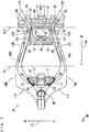
- Fig. 6 is a schematic enlarged side view for explaining the details of the shock-absorbing mechanism 50 of Fig. 1 .
- the main frame 1M is indicated by the one-dot and dash line.
- the shock-absorbing mechanism 50 includes the rear suspension 51, a first link member 52 and a second link member 53.
- the rear suspension 51 is provided to extend obliquely downwardly from a front portion of the vehicle to a rear portion of the vehicle and has seventh and eighth end portions E7, E8.
- the first link member 52 is formed to extend in one direction while bending mildly.
- One end portion of the first link member 52 is referred to as a first portion 52a, and the other end of the first link member 52 is referred to as a third portion 52c.
- a substantially center portion of the first link member 52 is referred to as a second portion 52b.
- the second link member 53 is a bar-shaped member extending linearly in one direction.
- One end portion of the second link member 53 is referred to as a fourth portion 53a, and the other end portion of the second link member 53 is referred to as a fifth portion 53b.
- the seventh end portion E7 of the rear suspension 51 is connected to the link shaft 31S provided at the second coupling member 30.
- the first portion 52a of the first link member 52 is connected to the eighth end portion E8 of the rear suspension 51.
- a link member connecting portion 6P is provided at the front half portion of the rear arm 6 to project upwardly.
- the second portion 52b of the first link member 52 is connected to the link member connecting portion 6P of the rear arm 6.
- the fourth portion 53a of the second link member 53 is connected to the third portion 52c of the first link member 52.
- the fifth portion 53b of the second link member 53 is connected to the link shaft 41S provided at the third coupling member 40.
- each of the connecting portion between the second coupling member 30 and the rear suspension 51 the connecting portion between the rear suspension 51 and the first link member 52 and the connecting portion between the first link member 52 and the rear arm 6, one member and the other member are rotatable relative to each other about an axis in parallel with the left-and-right direction LR.
- one member and the other member are rotatable relative to each other about an axis in parallel with the left-and-right direction LR.
- part of the rear arm 6 is supported at the main frame 1M via the rear suspension 51 so as to be swingable in the up-and-down direction of the vehicle.
- the rear suspension 51 absorbs the transmitted shock.
- the left and right engine brackets 60L, 60R are connected to the body frame 1 and the engine 5 with the plurality of bolts B4.
- desired riding comfort in the motorcycle 100 is realized by adjustment of the shape and material of the left and right engine brackets 60L, 60R.
- As the material for the engine brackets 60L, 60R, metal, a reinforced resin or the like can be used.
- Fig. 7 is an external perspective view showing one example of the rear frame 1R being attached to the main frame 1M of Fig. 2 together with the plurality of frame attachment members.
- the rear frame 1R is constituted by a pair of left and right upper rails 81 and a pair of left and right lower rails 82.
- the left and right upper rails 81 are formed to be arranged in the left-and-right direction LR and extend in the front-and-rear direction FB, and their rear end portions are connected to each other.
- the left and right lower rails 82 are formed to extend downwardly and forwardly from positions in the vicinity of the rear ends of the left and right upper rails 81. With such a configuration, the rear frame 1R has substantially a U-shape in a plan view of the vehicle.
- a front end portion 81e of the left upper rail 81 is arranged leftwardly of the left frame connecting portion 12S to come into contact with the left frame connecting portion 12S.
- the front end portion 81e of the left upper rail 81, the left frame connecting portion 12S and the third end portion E3 of the second coupling member 30 are connected to one another with one bolt B2.
- a front end portion 81e of the right upper rail 81 is arranged rightwardly of the right frame connecting portion 12S to come into contact with the right frame connecting portion 12S.
- the front end portion 81e of the right upper rail 81, the right frame connecting portion 12S and the fourth end portion E4 of the second coupling member 30 are connected to one another with one bolt B2 ( Fig. 4 ).
- the front end portion 82e of the left lower rail 82 is arranged rightwardly of the left frame connecting portion 13S to come into contact with the left frame connecting portion 13S.
- the front end portion 82e of the left lower rail 82 and the left frame connecting portion 13S are connected to each other with one bolt B11.
- the front end portion 82e of the right lower rail 82 is arranged leftwardly of the right frame connecting portion 13S to come into contact with the right frame connecting portion 13S.
- the front end portion 82e of the right lower rail 82 and the right frame connecting portion 13S are connected to each other with one bolt.
- the rear frame 1R is attached to the main frame 1M as described above, and then the surfaces of the main and rear frames 1M, 1R are painted. In this case, it is not necessary to paint the main and rear frames 1M, 1R separately. Therefore, it is not necessary to perform masking on the connecting portions between the main and rear frames 1M, 1R. Therefore, a manufacturing cost of the motorcycle 100 can be reduced.
- the head pipe HP is an example of a head pipe
- the main rails 1ML, 1MR are an example of a pair of left and right main rails
- the body frame 1 is an example of a body frame
- the front portions 11L, 11R are an example of front portions of the left and right main rails
- the first coupling member 20 is an example of a first coupling member.
- middle portions 12L, 12R are an example of middle portions of the left and right main rails
- the second coupling member 30 is an example of a second coupling member
- the lower ends of the rear portions 13L, 13R are an example of rear end portions of the left and right main rails
- the third coupling member 40 is an example of a third coupling member.
- the rear wheel 7 is an example of a drive wheel
- the bolt B1 is an example of a first bolt
- the bolt B2 is an example of a second bolt
- the bolt B3 is an example of a third bolt
- the engine bracket 60L is an example of a left engine bracket
- the engine bracket 60R is an example of a right engine bracket
- the bolt B4 is an example of fourth and fifth bolts.
Landscapes
- Engineering & Computer Science (AREA)
- Mechanical Engineering (AREA)
- Chemical & Material Sciences (AREA)
- Combustion & Propulsion (AREA)
- Transportation (AREA)
- Automatic Cycles, And Cycles In General (AREA)
- Body Structure For Vehicles (AREA)
- Axle Suspensions And Sidecars For Cycles (AREA)
Applications Claiming Priority (1)
| Application Number | Priority Date | Filing Date | Title |
|---|---|---|---|
| JP2019188039A JP2021062724A (ja) | 2019-10-11 | 2019-10-11 | 鞍乗型車両 |
Publications (2)
| Publication Number | Publication Date |
|---|---|
| EP3805086A1 true EP3805086A1 (de) | 2021-04-14 |
| EP3805086B1 EP3805086B1 (de) | 2022-06-15 |
Family
ID=72801340
Family Applications (1)
| Application Number | Title | Priority Date | Filing Date |
|---|---|---|---|
| EP20200496.6A Active EP3805086B1 (de) | 2019-10-11 | 2020-10-07 | Grätschsitzfahrzeug |
Country Status (9)
| Country | Link |
|---|---|
| US (1) | US11975790B2 (de) |
| EP (1) | EP3805086B1 (de) |
| JP (1) | JP2021062724A (de) |
| CN (1) | CN112644634B (de) |
| AR (1) | AR122314A1 (de) |
| BR (1) | BR102020020539A2 (de) |
| CA (1) | CA3095643C (de) |
| PH (1) | PH12020050383A1 (de) |
| TW (1) | TWI753597B (de) |
Families Citing this family (1)
| Publication number | Priority date | Publication date | Assignee | Title |
|---|---|---|---|---|
| IT202000005860A1 (it) * | 2020-03-19 | 2021-09-19 | Piaggio & C Spa | Veicolo a sella cavalcabile provvisto di telaio con rigidezza ridotta verso i movimenti di imbardata. |
Citations (5)
| Publication number | Priority date | Publication date | Assignee | Title |
|---|---|---|---|---|
| JPS61129383A (ja) * | 1984-11-26 | 1986-06-17 | ヤマハ発動機株式会社 | 自動二輪車の車体フレ−ム |
| JPS62189293U (de) * | 1986-05-26 | 1987-12-02 | ||
| JP2013103565A (ja) | 2011-11-11 | 2013-05-30 | Suzuki Motor Corp | 鞍乗型車両のフレーム構造 |
| CN206679167U (zh) * | 2017-04-07 | 2017-11-28 | 曹功仓 | 一种无需焊接自行车车架 |
| EP3674195A1 (de) * | 2018-12-28 | 2020-07-01 | e-moovee GmbH | Hauptkörperrahmen für elektromotorrad und elektromotorrad |
Family Cites Families (43)
| Publication number | Priority date | Publication date | Assignee | Title |
|---|---|---|---|---|
| JPS59134071A (ja) | 1983-01-20 | 1984-08-01 | ヤマハ発動機株式会社 | 自動二輪車の車体フレ−ム |
| JPS59213582A (ja) | 1983-05-18 | 1984-12-03 | 川崎重工業株式会社 | フレ−ム分割型自動二輪車 |
| JPS61178276A (ja) | 1985-01-31 | 1986-08-09 | ヤマハ発動機株式会社 | 自動二輪車の車体フレ−ム |
| JPH075109B2 (ja) | 1986-01-21 | 1995-01-25 | ヤマハ発動機株式会社 | 自動二輪車等の車両用フレ−ム |
| JPS63129688U (de) | 1987-02-17 | 1988-08-24 | ||
| JPH01175989U (de) | 1988-05-25 | 1989-12-14 | ||
| JP3395934B2 (ja) | 1995-05-01 | 2003-04-14 | ヤマハ発動機株式会社 | 電動スクーターおよび電動スクーター用補助具 |
| JP3605504B2 (ja) | 1997-10-23 | 2004-12-22 | 本田技研工業株式会社 | 電動補助自転車 |
| JP4015265B2 (ja) | 1998-03-31 | 2007-11-28 | 本田技研工業株式会社 | 自動2輪車の車体フレーム構造 |
| JP3933314B2 (ja) | 1998-08-10 | 2007-06-20 | 本田技研工業株式会社 | 二輪車用車体フレーム及びその製造方法 |
| JP2001172796A (ja) | 1999-12-13 | 2001-06-26 | Yamaha Motor Co Ltd | アルミ合金製構造部材およびそれを使用したモータサイクル |
| JP3901954B2 (ja) * | 2001-04-04 | 2007-04-04 | 本田技研工業株式会社 | 自動二輪車のリヤサスペンション取付構造 |
| US6505847B1 (en) | 2001-10-15 | 2003-01-14 | Paramount Custom Cycles | Frame with built-in suspension |
| JP4015516B2 (ja) | 2002-09-24 | 2007-11-28 | ヤマハ発動機株式会社 | 自動二輪車用車体フレーム |
| JP4141493B2 (ja) * | 2007-09-03 | 2008-08-27 | 本田技研工業株式会社 | シートレール構造 |
| CN101181920A (zh) | 2007-12-18 | 2008-05-21 | 李建春 | 一种组装式摩托车车架 |
| DE102008011851B4 (de) | 2008-02-29 | 2010-11-04 | Markus Christ | Trägerstruktur für ein einen Elektroantrieb aufweisendes Motorrad |
| JP5142781B2 (ja) * | 2008-03-27 | 2013-02-13 | 本田技研工業株式会社 | 自動二輪車 |
| JP5295688B2 (ja) | 2008-09-05 | 2013-09-18 | ヤマハ発動機株式会社 | 自動二輪車 |
| JP5112237B2 (ja) | 2008-09-25 | 2013-01-09 | 本田技研工業株式会社 | 自動二輪車のバッテリ配置構造 |
| JP2010083380A (ja) | 2008-09-30 | 2010-04-15 | Honda Motor Co Ltd | 自動2輪車の車体フレーム構造 |
| JP5235795B2 (ja) * | 2009-06-19 | 2013-07-10 | 本田技研工業株式会社 | 自動二輪車 |
| JP5530230B2 (ja) | 2010-03-16 | 2014-06-25 | 本田技研工業株式会社 | 鞍乗型車両の制振装置 |
| JP5595302B2 (ja) * | 2011-02-23 | 2014-09-24 | 本田技研工業株式会社 | 鞍乗り型車両 |
| JP2012192773A (ja) * | 2011-03-15 | 2012-10-11 | Honda Motor Co Ltd | 自動二輪車における電装品の支持構造 |
| JP5879173B2 (ja) | 2012-03-29 | 2016-03-08 | 本田技研工業株式会社 | 電動式鞍乗り型車両 |
| CN108100129B (zh) * | 2013-03-15 | 2020-08-18 | 北极星工业有限公司 | 两轮车辆 |
| JP2015074352A (ja) | 2013-10-09 | 2015-04-20 | ヤマハ発動機株式会社 | 車体フレームおよびそれを備えた鞍乗型車両 |
| JP6158943B2 (ja) | 2013-11-07 | 2017-07-05 | 川崎重工業株式会社 | 鞍乗型車両の車体フレーム構造 |
| JP6122820B2 (ja) | 2014-09-30 | 2017-04-26 | 本田技研工業株式会社 | 鞍乗り型車両 |
| JP6459554B2 (ja) | 2015-01-26 | 2019-01-30 | 日産自動車株式会社 | 自動車ボディの塗装乾燥方法 |
| JP6605324B2 (ja) * | 2015-12-24 | 2019-11-13 | 川崎重工業株式会社 | スイングアームの支持構造 |
| JP2017121850A (ja) | 2016-01-06 | 2017-07-13 | ヤマハ発動機株式会社 | 鞍乗型車両 |
| FR3047469B1 (fr) | 2016-02-09 | 2018-02-23 | Renault S.A.S. | Dispositif de support d'un composant de vehicule automobile |
| JP6473117B2 (ja) | 2016-09-30 | 2019-02-20 | 本田技研工業株式会社 | 電動車両 |
| CN106394685B (zh) | 2016-11-12 | 2018-08-14 | 杭州衡源汽车科技有限公司 | 电动汽车底盘总成防撞系统 |
| CN206317942U (zh) | 2016-12-26 | 2017-07-11 | 重庆秋航机械有限责任公司 | 摩托车加固车架和摩托车 |
| JP6826906B2 (ja) | 2017-02-14 | 2021-02-10 | 川崎重工業株式会社 | 自動二輪車用フレーム |
| JP6671403B2 (ja) | 2018-02-28 | 2020-03-25 | 本田技研工業株式会社 | エンジンハンガ構造 |
| JP7029996B2 (ja) * | 2018-03-28 | 2022-03-04 | 本田技研工業株式会社 | 鞍乗り型車両のシートフレーム構造 |
| US11117637B2 (en) * | 2018-07-25 | 2021-09-14 | Harley-Davidson Motor Company Group, LLC | Motorcycle frame |
| US20210094650A1 (en) * | 2019-10-01 | 2021-04-01 | Christopher Sanders | Progressive cycle suspension linkage |
| JP2021062716A (ja) * | 2019-10-11 | 2021-04-22 | ヤマハ発動機株式会社 | 車体フレームの製造方法 |
-
2019
- 2019-10-11 JP JP2019188039A patent/JP2021062724A/ja active Pending
-
2020
- 2020-10-06 BR BR102020020539-0A patent/BR102020020539A2/pt active Search and Examination
- 2020-10-07 TW TW109134751A patent/TWI753597B/zh active
- 2020-10-07 EP EP20200496.6A patent/EP3805086B1/de active Active
- 2020-10-07 AR ARP200102777A patent/AR122314A1/es active IP Right Grant
- 2020-10-08 CA CA3095643A patent/CA3095643C/en active Active
- 2020-10-09 PH PH12020050383A patent/PH12020050383A1/en unknown
- 2020-10-09 US US17/067,153 patent/US11975790B2/en active Active
- 2020-10-10 CN CN202011077629.8A patent/CN112644634B/zh active Active
Patent Citations (5)
| Publication number | Priority date | Publication date | Assignee | Title |
|---|---|---|---|---|
| JPS61129383A (ja) * | 1984-11-26 | 1986-06-17 | ヤマハ発動機株式会社 | 自動二輪車の車体フレ−ム |
| JPS62189293U (de) * | 1986-05-26 | 1987-12-02 | ||
| JP2013103565A (ja) | 2011-11-11 | 2013-05-30 | Suzuki Motor Corp | 鞍乗型車両のフレーム構造 |
| CN206679167U (zh) * | 2017-04-07 | 2017-11-28 | 曹功仓 | 一种无需焊接自行车车架 |
| EP3674195A1 (de) * | 2018-12-28 | 2020-07-01 | e-moovee GmbH | Hauptkörperrahmen für elektromotorrad und elektromotorrad |
Non-Patent Citations (1)
| Title |
|---|
| SCHULTZ: "Chapter 1: DELTA-11 -Building the Worlds Most Efficient, Practical Motorcycle Schultz Engineering, LLC 2011 Concept Vehicle DELTA-11 tm -Developing the Worlds Most Efficient, Practical Electric Motorcycle", 6 October 2011 (2011-10-06), XP055770716, Retrieved from the Internet <URL:https://www.schultzengineering.us/delta-11-1.htm> [retrieved on 20210201] * |
Also Published As
| Publication number | Publication date |
|---|---|
| US11975790B2 (en) | 2024-05-07 |
| CA3095643C (en) | 2023-10-24 |
| AR122314A1 (es) | 2022-08-31 |
| EP3805086B1 (de) | 2022-06-15 |
| CA3095643A1 (en) | 2021-04-11 |
| CN112644634B (zh) | 2022-06-07 |
| JP2021062724A (ja) | 2021-04-22 |
| PH12020050383A1 (en) | 2021-04-19 |
| TWI753597B (zh) | 2022-01-21 |
| BR102020020539A2 (pt) | 2021-08-24 |
| TW202126527A (zh) | 2021-07-16 |
| US20210107585A1 (en) | 2021-04-15 |
| CN112644634A (zh) | 2021-04-13 |
Similar Documents
| Publication | Publication Date | Title |
|---|---|---|
| US7618063B2 (en) | Vehicle body frame structure for all-terrain vehicle | |
| US7503575B2 (en) | Body frame of two-wheeled vehicle | |
| WO2012165332A1 (ja) | 自動二輪車 | |
| US20070095624A1 (en) | Saddle-type vehicle and steering damper for use in the same | |
| US8776933B2 (en) | Vehicle body frame for motorcycle, and motorcycle incorporating the same | |
| JP6476224B2 (ja) | 鞍乗型車両のリアフェンダ支持構造 | |
| CA3094214C (en) | Straddled vehicle with detachable side cases | |
| US10464632B2 (en) | Straddled vehicle | |
| EP3805086A1 (de) | Grätschsitzfahrzeug | |
| US20160280301A1 (en) | Fuel tank for straddle type vehicle | |
| EP1992555B1 (de) | Vorderradaufhängungsvorrichtung für ein Motorrad | |
| US11110986B2 (en) | Manufacturing method of body frame | |
| CN108657345B (zh) | 跨骑型车辆的车身结构 | |
| JP2016088231A (ja) | 鞍乗型車両 | |
| EP1743831A1 (de) | Fahrzeug mit lenkbarem Hinterrad | |
| EP3305641B1 (de) | Grätschsitzfahrzeug | |
| WO2023139591A1 (en) | Steering system of a vehicle | |
| JPS6346313Y2 (de) | ||
| JP2012183892A (ja) | 鞍乗り型車両 |
Legal Events
| Date | Code | Title | Description |
|---|---|---|---|
| PUAI | Public reference made under article 153(3) epc to a published international application that has entered the european phase |
Free format text: ORIGINAL CODE: 0009012 |
|
| STAA | Information on the status of an ep patent application or granted ep patent |
Free format text: STATUS: REQUEST FOR EXAMINATION WAS MADE |
|
| 17P | Request for examination filed |
Effective date: 20201007 |
|
| AK | Designated contracting states |
Kind code of ref document: A1 Designated state(s): AL AT BE BG CH CY CZ DE DK EE ES FI FR GB GR HR HU IE IS IT LI LT LU LV MC MK MT NL NO PL PT RO RS SE SI SK SM TR |
|
| AX | Request for extension of the european patent |
Extension state: BA ME |
|
| RBV | Designated contracting states (corrected) |
Designated state(s): AL AT BE BG CH CY CZ DE DK EE ES FI FR GB GR HR HU IE IS IT LI LT LU LV MC MK MT NL NO PL PT RO RS SE SI SK SM TR |
|
| GRAP | Despatch of communication of intention to grant a patent |
Free format text: ORIGINAL CODE: EPIDOSNIGR1 |
|
| STAA | Information on the status of an ep patent application or granted ep patent |
Free format text: STATUS: GRANT OF PATENT IS INTENDED |
|
| INTG | Intention to grant announced |
Effective date: 20220209 |
|
| GRAS | Grant fee paid |
Free format text: ORIGINAL CODE: EPIDOSNIGR3 |
|
| GRAA | (expected) grant |
Free format text: ORIGINAL CODE: 0009210 |
|
| STAA | Information on the status of an ep patent application or granted ep patent |
Free format text: STATUS: THE PATENT HAS BEEN GRANTED |
|
| AK | Designated contracting states |
Kind code of ref document: B1 Designated state(s): AL AT BE BG CH CY CZ DE DK EE ES FI FR GB GR HR HU IE IS IT LI LT LU LV MC MK MT NL NO PL PT RO RS SE SI SK SM TR |
|
| REG | Reference to a national code |
Ref country code: CH Ref legal event code: EP Ref country code: GB Ref legal event code: FG4D |
|
| REG | Reference to a national code |
Ref country code: IE Ref legal event code: FG4D |
|
| REG | Reference to a national code |
Ref country code: DE Ref legal event code: R096 Ref document number: 602020003548 Country of ref document: DE |
|
| REG | Reference to a national code |
Ref country code: AT Ref legal event code: REF Ref document number: 1498242 Country of ref document: AT Kind code of ref document: T Effective date: 20220715 |
|
| REG | Reference to a national code |
Ref country code: LT Ref legal event code: MG9D |
|
| REG | Reference to a national code |
Ref country code: NL Ref legal event code: MP Effective date: 20220615 |
|
| PG25 | Lapsed in a contracting state [announced via postgrant information from national office to epo] |
Ref country code: SE Free format text: LAPSE BECAUSE OF FAILURE TO SUBMIT A TRANSLATION OF THE DESCRIPTION OR TO PAY THE FEE WITHIN THE PRESCRIBED TIME-LIMIT Effective date: 20220615 Ref country code: NO Free format text: LAPSE BECAUSE OF FAILURE TO SUBMIT A TRANSLATION OF THE DESCRIPTION OR TO PAY THE FEE WITHIN THE PRESCRIBED TIME-LIMIT Effective date: 20220915 Ref country code: LT Free format text: LAPSE BECAUSE OF FAILURE TO SUBMIT A TRANSLATION OF THE DESCRIPTION OR TO PAY THE FEE WITHIN THE PRESCRIBED TIME-LIMIT Effective date: 20220615 Ref country code: HR Free format text: LAPSE BECAUSE OF FAILURE TO SUBMIT A TRANSLATION OF THE DESCRIPTION OR TO PAY THE FEE WITHIN THE PRESCRIBED TIME-LIMIT Effective date: 20220615 Ref country code: GR Free format text: LAPSE BECAUSE OF FAILURE TO SUBMIT A TRANSLATION OF THE DESCRIPTION OR TO PAY THE FEE WITHIN THE PRESCRIBED TIME-LIMIT Effective date: 20220916 Ref country code: FI Free format text: LAPSE BECAUSE OF FAILURE TO SUBMIT A TRANSLATION OF THE DESCRIPTION OR TO PAY THE FEE WITHIN THE PRESCRIBED TIME-LIMIT Effective date: 20220615 Ref country code: BG Free format text: LAPSE BECAUSE OF FAILURE TO SUBMIT A TRANSLATION OF THE DESCRIPTION OR TO PAY THE FEE WITHIN THE PRESCRIBED TIME-LIMIT Effective date: 20220915 |
|
| REG | Reference to a national code |
Ref country code: AT Ref legal event code: MK05 Ref document number: 1498242 Country of ref document: AT Kind code of ref document: T Effective date: 20220615 |
|
| PG25 | Lapsed in a contracting state [announced via postgrant information from national office to epo] |
Ref country code: RS Free format text: LAPSE BECAUSE OF FAILURE TO SUBMIT A TRANSLATION OF THE DESCRIPTION OR TO PAY THE FEE WITHIN THE PRESCRIBED TIME-LIMIT Effective date: 20220615 Ref country code: LV Free format text: LAPSE BECAUSE OF FAILURE TO SUBMIT A TRANSLATION OF THE DESCRIPTION OR TO PAY THE FEE WITHIN THE PRESCRIBED TIME-LIMIT Effective date: 20220615 |
|
| PG25 | Lapsed in a contracting state [announced via postgrant information from national office to epo] |
Ref country code: NL Free format text: LAPSE BECAUSE OF FAILURE TO SUBMIT A TRANSLATION OF THE DESCRIPTION OR TO PAY THE FEE WITHIN THE PRESCRIBED TIME-LIMIT Effective date: 20220615 |
|
| PG25 | Lapsed in a contracting state [announced via postgrant information from national office to epo] |
Ref country code: SM Free format text: LAPSE BECAUSE OF FAILURE TO SUBMIT A TRANSLATION OF THE DESCRIPTION OR TO PAY THE FEE WITHIN THE PRESCRIBED TIME-LIMIT Effective date: 20220615 Ref country code: SK Free format text: LAPSE BECAUSE OF FAILURE TO SUBMIT A TRANSLATION OF THE DESCRIPTION OR TO PAY THE FEE WITHIN THE PRESCRIBED TIME-LIMIT Effective date: 20220615 Ref country code: RO Free format text: LAPSE BECAUSE OF FAILURE TO SUBMIT A TRANSLATION OF THE DESCRIPTION OR TO PAY THE FEE WITHIN THE PRESCRIBED TIME-LIMIT Effective date: 20220615 Ref country code: PT Free format text: LAPSE BECAUSE OF FAILURE TO SUBMIT A TRANSLATION OF THE DESCRIPTION OR TO PAY THE FEE WITHIN THE PRESCRIBED TIME-LIMIT Effective date: 20221017 Ref country code: ES Free format text: LAPSE BECAUSE OF FAILURE TO SUBMIT A TRANSLATION OF THE DESCRIPTION OR TO PAY THE FEE WITHIN THE PRESCRIBED TIME-LIMIT Effective date: 20220615 Ref country code: EE Free format text: LAPSE BECAUSE OF FAILURE TO SUBMIT A TRANSLATION OF THE DESCRIPTION OR TO PAY THE FEE WITHIN THE PRESCRIBED TIME-LIMIT Effective date: 20220615 Ref country code: CZ Free format text: LAPSE BECAUSE OF FAILURE TO SUBMIT A TRANSLATION OF THE DESCRIPTION OR TO PAY THE FEE WITHIN THE PRESCRIBED TIME-LIMIT Effective date: 20220615 Ref country code: AT Free format text: LAPSE BECAUSE OF FAILURE TO SUBMIT A TRANSLATION OF THE DESCRIPTION OR TO PAY THE FEE WITHIN THE PRESCRIBED TIME-LIMIT Effective date: 20220615 |
|
| PG25 | Lapsed in a contracting state [announced via postgrant information from national office to epo] |
Ref country code: PL Free format text: LAPSE BECAUSE OF FAILURE TO SUBMIT A TRANSLATION OF THE DESCRIPTION OR TO PAY THE FEE WITHIN THE PRESCRIBED TIME-LIMIT Effective date: 20220615 Ref country code: IS Free format text: LAPSE BECAUSE OF FAILURE TO SUBMIT A TRANSLATION OF THE DESCRIPTION OR TO PAY THE FEE WITHIN THE PRESCRIBED TIME-LIMIT Effective date: 20221015 |
|
| REG | Reference to a national code |
Ref country code: DE Ref legal event code: R097 Ref document number: 602020003548 Country of ref document: DE |
|
| PG25 | Lapsed in a contracting state [announced via postgrant information from national office to epo] |
Ref country code: AL Free format text: LAPSE BECAUSE OF FAILURE TO SUBMIT A TRANSLATION OF THE DESCRIPTION OR TO PAY THE FEE WITHIN THE PRESCRIBED TIME-LIMIT Effective date: 20220615 |
|
| PLBE | No opposition filed within time limit |
Free format text: ORIGINAL CODE: 0009261 |
|
| STAA | Information on the status of an ep patent application or granted ep patent |
Free format text: STATUS: NO OPPOSITION FILED WITHIN TIME LIMIT |
|
| PG25 | Lapsed in a contracting state [announced via postgrant information from national office to epo] |
Ref country code: DK Free format text: LAPSE BECAUSE OF FAILURE TO SUBMIT A TRANSLATION OF THE DESCRIPTION OR TO PAY THE FEE WITHIN THE PRESCRIBED TIME-LIMIT Effective date: 20220615 |
|
| 26N | No opposition filed |
Effective date: 20230316 |
|
| PG25 | Lapsed in a contracting state [announced via postgrant information from national office to epo] |
Ref country code: SI Free format text: LAPSE BECAUSE OF FAILURE TO SUBMIT A TRANSLATION OF THE DESCRIPTION OR TO PAY THE FEE WITHIN THE PRESCRIBED TIME-LIMIT Effective date: 20220615 Ref country code: MC Free format text: LAPSE BECAUSE OF FAILURE TO SUBMIT A TRANSLATION OF THE DESCRIPTION OR TO PAY THE FEE WITHIN THE PRESCRIBED TIME-LIMIT Effective date: 20220615 |
|
| REG | Reference to a national code |
Ref country code: BE Ref legal event code: MM Effective date: 20221031 |
|
| PG25 | Lapsed in a contracting state [announced via postgrant information from national office to epo] |
Ref country code: LU Free format text: LAPSE BECAUSE OF NON-PAYMENT OF DUE FEES Effective date: 20221007 |
|
| P01 | Opt-out of the competence of the unified patent court (upc) registered |
Effective date: 20230527 |
|
| PG25 | Lapsed in a contracting state [announced via postgrant information from national office to epo] |
Ref country code: BE Free format text: LAPSE BECAUSE OF NON-PAYMENT OF DUE FEES Effective date: 20221031 |
|
| PG25 | Lapsed in a contracting state [announced via postgrant information from national office to epo] |
Ref country code: IE Free format text: LAPSE BECAUSE OF NON-PAYMENT OF DUE FEES Effective date: 20221007 |
|
| PGFP | Annual fee paid to national office [announced via postgrant information from national office to epo] |
Ref country code: IT Payment date: 20231031 Year of fee payment: 4 Ref country code: FR Payment date: 20231026 Year of fee payment: 4 Ref country code: DE Payment date: 20231020 Year of fee payment: 4 |
|
| PG25 | Lapsed in a contracting state [announced via postgrant information from national office to epo] |
Ref country code: CY Free format text: LAPSE BECAUSE OF FAILURE TO SUBMIT A TRANSLATION OF THE DESCRIPTION OR TO PAY THE FEE WITHIN THE PRESCRIBED TIME-LIMIT Effective date: 20220615 |