EP3790817B1 - Stapelbarer behälter - Google Patents
Stapelbarer behälter Download PDFInfo
- Publication number
- EP3790817B1 EP3790817B1 EP19725402.2A EP19725402A EP3790817B1 EP 3790817 B1 EP3790817 B1 EP 3790817B1 EP 19725402 A EP19725402 A EP 19725402A EP 3790817 B1 EP3790817 B1 EP 3790817B1
- Authority
- EP
- European Patent Office
- Prior art keywords
- side walls
- container
- collecting channel
- floor
- openings
- Prior art date
- Legal status (The legal status is an assumption and is not a legal conclusion. Google has not performed a legal analysis and makes no representation as to the accuracy of the status listed.)
- Active
Links
Images




Classifications
-
- B—PERFORMING OPERATIONS; TRANSPORTING
- B65—CONVEYING; PACKING; STORING; HANDLING THIN OR FILAMENTARY MATERIAL
- B65D—CONTAINERS FOR STORAGE OR TRANSPORT OF ARTICLES OR MATERIALS, e.g. BAGS, BARRELS, BOTTLES, BOXES, CANS, CARTONS, CRATES, DRUMS, JARS, TANKS, HOPPERS, FORWARDING CONTAINERS; ACCESSORIES, CLOSURES, OR FITTINGS THEREFOR; PACKAGING ELEMENTS; PACKAGES
- B65D21/00—Nestable, stackable or joinable containers; Containers of variable capacity
- B65D21/02—Containers specially shaped, or provided with fittings or attachments, to facilitate nesting, stacking, or joining together
- B65D21/0209—Containers specially shaped, or provided with fittings or attachments, to facilitate nesting, stacking, or joining together stackable or joined together one-upon-the-other in the upright or upside-down position
-
- B—PERFORMING OPERATIONS; TRANSPORTING
- B65—CONVEYING; PACKING; STORING; HANDLING THIN OR FILAMENTARY MATERIAL
- B65D—CONTAINERS FOR STORAGE OR TRANSPORT OF ARTICLES OR MATERIALS, e.g. BAGS, BARRELS, BOTTLES, BOXES, CANS, CARTONS, CRATES, DRUMS, JARS, TANKS, HOPPERS, FORWARDING CONTAINERS; ACCESSORIES, CLOSURES, OR FITTINGS THEREFOR; PACKAGING ELEMENTS; PACKAGES
- B65D21/00—Nestable, stackable or joinable containers; Containers of variable capacity
- B65D21/02—Containers specially shaped, or provided with fittings or attachments, to facilitate nesting, stacking, or joining together
- B65D21/0209—Containers specially shaped, or provided with fittings or attachments, to facilitate nesting, stacking, or joining together stackable or joined together one-upon-the-other in the upright or upside-down position
- B65D21/0213—Containers presenting a continuous stacking profile along the upper or lower edge of at least two opposite side walls
-
- B—PERFORMING OPERATIONS; TRANSPORTING
- B65—CONVEYING; PACKING; STORING; HANDLING THIN OR FILAMENTARY MATERIAL
- B65D—CONTAINERS FOR STORAGE OR TRANSPORT OF ARTICLES OR MATERIALS, e.g. BAGS, BARRELS, BOTTLES, BOXES, CANS, CARTONS, CRATES, DRUMS, JARS, TANKS, HOPPERS, FORWARDING CONTAINERS; ACCESSORIES, CLOSURES, OR FITTINGS THEREFOR; PACKAGING ELEMENTS; PACKAGES
- B65D81/00—Containers, packaging elements, or packages, for contents presenting particular transport or storage problems, or adapted to be used for non-packaging purposes after removal of contents
- B65D81/24—Adaptations for preventing deterioration or decay of contents; Applications to the container or packaging material of food preservatives, fungicides, pesticides or animal repellants
- B65D81/26—Adaptations for preventing deterioration or decay of contents; Applications to the container or packaging material of food preservatives, fungicides, pesticides or animal repellants with provision for draining away, or absorbing, or removing by ventilation, fluids, e.g. exuded by contents; Applications of corrosion inhibitors or desiccators
- B65D81/261—Adaptations for preventing deterioration or decay of contents; Applications to the container or packaging material of food preservatives, fungicides, pesticides or animal repellants with provision for draining away, or absorbing, or removing by ventilation, fluids, e.g. exuded by contents; Applications of corrosion inhibitors or desiccators for draining or collecting liquids without absorbing them
Definitions
- the invention relates to a stackable container for the transport and storage of goods and in particular to such a container with openings for the purpose of draining liquids from the interior of the container.
- Such a container is made, for example GB951746 known.
- a one-piece injection-moulded container is disclosed which has reinforcing ribs in the base and a number of drainage openings distributed over the base surface.
- the container At the upper edge of the side walls, the container has a step-shaped contour that curves outwards, which enables stacking of identical containers.
- U.S. 4,386,700 discloses a stackable container for transporting goods such as fish, having drain holes for removing liquid outside the container.
- the drain openings of a container at the top of a stack open into an outwardly inclined channel in the top edge of a container at the bottom of the stack. This prevents drained liquid from getting into the lower container and instead being routed to the outside.
- Another container is through DE29702706U known.
- the object of the present invention is to provide a stackable container from which liquids located on the bottom can flow.
- small liquids that have escaped from goods should be Floor can flow away, with these small amounts are collected and should not end up in the bottom container of the stack.
- large quantities of extinguishing water that are sprayed onto the containers in the event of a fire should also be able to get into the lower containers in the stack.
- a stackable container has a base and side walls extending perpendicularly upwardly from the base, the upper ends of the side walls being formed with stepped edges. Another container can be placed on the stepped edges, forming a stack of uniform containers.
- the container has a plurality of through openings on at least two opposite side walls, which are distributed over the lower ends of the side walls which rest on the floor.
- the openings open out on the outside of said side walls into a collecting channel which is formed in one piece with the bottom of the container and runs along the outside of the bottom.
- the outer wall of the collecting channel extends over the height of the vertical extent of the openings on the side walls of the container.
- the at least two opposite side walls of the container each have an outwardly directed projection on their outside, which extends outwards from the side wall over the collecting channel and protrudes beyond the lateral extension of the collecting channel and has a horizontally running surface at its lower end.
- each side wall of the container extends upwardly outside the lateral extension of the collecting trough and terminates in a horizontal surface at its uppermost level.
- the position and the lateral extent of the horizontal surface at the lower end of the projection of the side walls are at least overlapping with the Location and lateral extent of the top, horizontal surface of the stepped edges of the side walls.
- the invention allows small amounts of liquids accidentally spilling from goods in the container, such as a broken bottle or ripped package, to drain through the openings at the lower edge of the side walls from the bottom surface of the container and the rest Do not wet goods unnecessarily. Such small amounts flow out through the openings and into the collecting trough formed on the base, which runs along the outer edge of the base and the outer edge of which extends upwards over the area of the openings. In this way, small amounts of drained liquids remain trapped in the channel. They do not get out completely and the outer surfaces of the container and the contents of a container standing underneath in a stack are not soiled.
- the projection according to the invention on the outside of the side walls forms a type of roof that covers the collecting channel and extends downwards outside the outer edge of the collecting channel and ends there in a horizontal surface.
- the stepped edge of the upper ends of the side walls also forms a horizontal surface at its uppermost end.
- the horizontal surfaces of the projection and the step-shaped edge of the side walls and their coordination with one another in terms of their lateral extent ensure that the container according to the invention can be stacked.
- the lateral extensions of the two horizontal surfaces are at least partially overlapping. This enables a container according to the invention to be stacked on top of a container below by placing the lower horizontal surface of the projection of the side walls on the top horizontal surface of the stepped edge of the side walls of a container below.
- the roof-shaped projection of a container at the top of a stack of containers that stands on the stepped edge of the container below also forms, together with the collecting channel and the stepped edge, a space into which liquids can flow from the collecting channel when it is overfilled.
- the stepped design of the edges of the side walls according to the invention together with the outwardly directed projection on the side walls thus also offers possible fire protection for stacked containers according to the invention. If, due to a fire alarm, extinguishing liquid is sprayed in a warehouse with stacked containers according to the invention, the extinguishing liquid reaches the collecting channel on the bottom of the container via the drainage openings on the side walls. Since this usually involves large amounts of water or extinguishing liquid, it passes over the upper edge of the collecting channel into the free space between the collecting channel and the projection and between the stepped edge and the outer wall of the channel into the lower container. If several containers are stacked on top of each other, extinguishing liquid can get inside the entire stack. The spread of a fire can thus also be prevented or slowed down in the containers on the bottom of the stack.
- the invention expediently requires that when two containers are stacked, the lower outer surface of the collecting channel does not come into contact with the stepped edge of the container below. This means that the lower outer surface of the collecting channel runs over the lower, horizontal surface of the stepped edge of a container standing below.
- the stacking relies solely on the superimposition of the bottom horizontal surface of the projection on the top horizontal surface of the stepped edge of the side walls.
- additional recesses are arranged on the edge of the base at the height of the openings for the outflow of liquid from the base of the container, which also open into the collecting channel. This also facilitates the drainage of liquid from the container.
- the openings are arranged along the lower edge of two opposite side walls or circumferentially along all side walls, with the collecting channel running along the two relevant side walls or circumferentially along all side walls.
- FIG. 1 a stack of two containers 1 according to the invention is shown with four vertical side walls 2 which hold a rectangular bottom 3 .
- the outer lower floor area is denoted by 3a and is explained in more detail in connection with the following figures.
- the side walls 2 each have a stepped edge at their upper ends of the upwardly open container 1 with a first, lower horizontal surface 2a, a vertical surface 2b and a second, upper horizontal surface 2c, which forms the uppermost end of the edge.
- openings 4 are distributed over its length, which lead through the side walls.
- figure 2 shows the stack of containers 1 figure 1 in cross section.
- the stepped configuration of the upper edge of the side wall 2 is shown.
- the lower area of the side wall 2 there is an outwardly directed projection 2d.
- a gutter 3c is integrated with the bottom 3 of the container 1.
- the projection 2d protrudes beyond the outer wall 3c of the collecting channel and covers it.
- the stacking of the upper container 1 on the lower container 1 is enabled by means of a horizontal surface at the projection 2d and the upper horizontal surface 2c of the stepped edge of the side wall. This is shown in the detail of the area III, which is in the figure 3 is shown enlarged, explained.
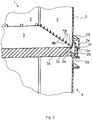
- the detail view in figure 3 shows the bottom 3 of an upper container 1 with lower floor level 3a and two of the side walls 2 with openings 4 along it lower edge of the side walls 2.
- the openings 4 extend not only in the side wall 2 but also over part of the base 3.
- the collecting channel is integrated with the base 3 in one piece. It is formed by an outwardly projecting overhang 3b and a vertical outer wall 3c extending upwards from the overhang 3b. Conveniently, the wall 3c extends above the level of the upper end of the openings 4 so that liquid from the openings is retained in the gutter. This is in the figure 4 shown.
- the length of the collecting channel 3b, 3c extends along all sides of the base 3 on which openings 4 are present.
- a roof-shaped projection is arranged on the outside of the side wall 2 and extends in the lower region of the side wall 2 and is formed in this embodiment by an outwardly directed surface 2d and a wall 2e extending downward from the end of the surface 2d.
- the shape of the projection as a whole can be any. In this example, it has a rectangular shape. However, it can be designed to be curved or sloping. It is essential for the projection that its lower end 2e has a horizontal end surface 2f.
- the end surface 2f rests on a horizontal surface 2c of the stepped edge of the side wall 2 of the lower tank 1.
- FIG. The stepped edge is formed by a first, lower, horizontal surface 2a, a vertical wall 2b extending upwardly therefrom, and the second, upper, horizontal surface 2c.
- the horizontal surface 2f of the projection and the horizontal surface 2c of the edge ensure that the containers 1 according to the invention can be stacked. For this purpose, their lateral position relative to the side wall 2 and their lateral dimensions must at least overlap.
- the projection 2d, 2e together with the stepped edge 2a, b, c and the collecting channel 3b, c form a free space through which liquids can flow into the lower container, as indicated by the arrows in figure 5 is shown.
- This is particularly the case when larger amounts of liquid as in If a fire is extinguished, get from the upper container through the openings 4 into the collecting channel and flood it and get over the wall 3c.
- the extinguishing liquid then passes directly through the spaces between the collecting channel 3b and c and the edge surfaces 2a and b into the lower container of the stack. Thanks to the closed free space, the liquid does not escape to the outside.
- the lateral extent of the horizontal surface 2a of the stepped edge of the side wall 2 runs outside the lateral extent of the collecting channel. That is, the vertical surface 2b of the stepped edge extends outside the vertical wall 3c of the gutter.
- the lower floor level 3a in the area of the collecting channel must not lie on the horizontal surface 2a of the lower container.
- the lower horizontal end surface 2f of the projection 2d rests on the horizontal surface 2c of the stepped rim.
- the lateral extent of the projection must be matched to the lateral extent of the surface 2c of the rim, in that the two horizontal surfaces are at least overlapping.
- the lateral extent of the horizontal surface 2f of the projection is entirely within the top horizontal surface of the stepped rim to facilitate stacking.
Landscapes
- Engineering & Computer Science (AREA)
- Mechanical Engineering (AREA)
- Food Science & Technology (AREA)
- Stackable Containers (AREA)
Description
- Die Erfindung betrifft einen stapelbaren Behälter für den Transport und die Lagerung von Waren und insbesondere einen solchen Behälter mit Öffnungen zwecks Abfluss von Flüssigkeiten aus dem Behälterinnern.
- Ein solcher Behälter ist zum Beispiel aus
GB951746 -
US 4,386,700 offenbart einen stapelbaren Behälter für den Transport von Waren, wie zum Beispiel Fisch, der Abflussöffnungen aufweist zur Entfernung von Flüssigkeit aus dem Behälter hinaus. Die Abflussöffnungen eines oben in einem Stapel stehenden Behälters münden in einen auswärts geneigten Kanal im oberen Rand eines im Stapel unten stehenden Behälters. Dadurch wird vermieden, dass abgeflossene Flüssigkeit in den unteren Behälter gelangt und stattdessen nach aussen geleitet wird. Ein weiterer Behälter ist durchDE29702706U bekannt. - Der vorliegenden Erfindung ist die Aufgabe gestellt, einen stapelbaren Behälter zu schaffen, aus dem auf dessen Boden sich befindende Flüssigkeiten fliessen können. Einerseits sollen kleine, aus Waren ausgeflossene Flüssigkeiten vom Boden wegfliessen können, wobei diese kleinen Mengen aufgefangen werden und nicht in den unteren Behälters des Stapels gelangen sollen. Anderseits sollen grosse Mengen von Löschwasser, die im Fall eines Brandes auf die Behälter gesprüht werden auch in untere Behälter im Stapel gelangen können.
- Diese Aufgabe wird erfindungsgemäss durch einen stapelbaren Behälter gemäss Anspruch 1 gelöst.
- Ein stapelbarer Behälter weist einen Boden und senkrecht vom Boden sich nach oben erstreckende Seitenwände auf, wobei die oberen Enden der Seitenwände mit stufenförmigen Rändern ausgebildet sind. Ein weiterer Behälter kann auf die stufenförmigen Ränder gestellt werden, wodurch ein Stapel gleichförmiger Behälter gebildet wird.
- Erfindungsgemäss weist der Behälter an mindestens zwei gegenüberliegenden Seitenwänden eine Vielzahl durchgehender Öffnungen auf, die über die unteren Enden der Seitenwände, die dem Boden anliegen, verteilt sind. Die Öffnungen münden an der Aussenseite der genannten Seitenwände in eine Auffangrinne, die einstückig mit dem Boden des Behälters gebildet ist und entlang den Aussenseiten des Bodens verläuft. Die äussere Wand der Auffangrinne erstreckt sich dabei über die Höhe der vertikalen Ausdehnung der Öffnungen an den Seitenwänden des Behälters.
- Zusätzlich weisen die mindestens zwei gegenüberliegenden Seitenwände des Behälters jeweils an ihrer Aussenseite einen nach aussen gerichteten Vorsprung auf, der sich von der Seitenwand über die Auffangrinne nach aussen erstreckt und über die seitliche Ausdehnung der Auffangrinne hinausragt und an seinem unteren Ende eine horizontal verlaufende Fläche aufweist.
- Zudem verläuft die vertikale Fläche des stufenförmigen Rands jeder Seitenwand des Behälters jeweils ausserhalb der seitlichen Ausdehnung der Auffangrinne nach oben und endet auf seiner obersten Ebene in einer horizontalen Fläche.
- Zudem sind die Lage und die seitliche Ausdehnung der horizontalen Fläche am unteren Ende des Vorsprungs der Seitenwände mindestens überlappend mit der Lage und der seitlichen Ausdehnung der obersten, horizontalen Fläche der stufenförmigen Ränder der Seitenwände.
- Die Erfindung ermöglicht, dass kleine Mengen von Flüssigkeiten, die aus Versehen aus Waren im Behälter ausfliessen, wie zum Beispiel aus einer zerbrochenen Flasche oder aus einer gerissenen Verpackung, durch die Öffnungen am unteren Rand der Seitenwände von der Bodenfläche des Behälters abfliessen können und die restlichen Waren nicht unnötig benetzen. Solche kleinen Mengen fliessen durch die Öffnungen nach aussen und in die am Boden gebildete Auffangrinne, die entlang dem äusseren Rand des Bodens verläuft und deren äusserer Rand sich nach oben über den Bereich der Öffnungen erstreckt. So bleiben kleine Mengen abgeflossener Flüssigkeiten in der Rinne gefangen. Sie gelangen nicht gänzlich nach aussen und die Aussenflächen des Behälters und der Inhalt eines in einem Stapel darunter stehenden Behälters werden nicht verschmutzt.
- Der erfindungsgemässe Vorsprung an den Aussenseiten der Seitenwände bildet jeweils eine Art Dach, die die Auffangrinne überdeckt und erstreckt sich dabei ausserhalb des äusseren Rands der Auffangrinne nach unten und endet dort in einer horizontalen Fläche. Der stufenförmige Rand der oberen Enden der Seitenwände bildet jeweils an seinem obersten Ende ebenfalls eine horizontale Fläche. Die horizontalen Flächen des Vorsprungs und des stufenförmigen Rands der Seitenwände sowie deren Abstimmung aufeinander in ihrer seitlichen Ausdehnung gewährleisten die Stapelbarkeit des erfindungsgemässen Behälters. Hierzu sind die seitlichen Ausdehnungen der beiden horizontalen Flächen mindestens zum Teil überlappend. Dies ermöglicht, dass ein erfindungsgemässer Behälter auf einen unten stehenden Behälter gestapelt werden kann, indem die untere, horizontale Fläche des Vorsprungs der Seitenwände auf die oberste, horizontale Fläche des stufenförmigen Rands der Seitenwände eines unten stehenden Behälters gestellt werden kann.
- Der dachförmige Vorsprung eines in einem Stapel von Behältern oberen Behälters der auf dem stufenförmigen Rand des unten stehenden Behälters steht, bildet zudem zusammen mit der Auffangrinne und dem stufenförmigen Rand einen Raum, in den Flüssigkeiten aus der Auffangrinne fliessen können, wenn diese überfüllt wird. Zwischen der vertikalen Fläche der stufenförmigen Ränder der Seitenwände und der äusseren Wand der Auffangrinne besteht ein Freiraum, sodass Flüssigkeiten, die über den Rand der Auffangrinne treten durch diesen Freiraum nach unten in den unten stehenden Behälter fliessen.
- Die erfindungsgemässe stufenförmige Ausbildung der Ränder der Seitenwände zusammen mit dem nach aussen gerichteten Vorsprung an den Seitenwänden bietet dadurch auch einen möglichen Brandschutz für gestapelte erfindungsgemässe Behälter an. Wird aufgrund eines Brandalarms Löschflüssigkeit in einem Lager mit gestapelten erfindungsgemässen Behältern verspritzt, so gelangt die Löschflüssigkeit über die Abflussöffnungen an den Seitenwänden in die Auffangrinne am Boden des Behälters. Da es sich dabei in der Regel um grössere Mengen von Wasser oder Löschflüssigkeit handelt, gelangt diese über den oberen Rand der Auffangrinne in den Freiraum zwischen Auffangrinne und Vorsprung und zwischen dem stufenförmigen Rand und der äusseren Wand der Rinne in den unteren Behälter. Sind mehrere Behälter übereinander gestapelt, so kann Löschflüssigkeit in das Innere des gesamten Stapels gelangen. Eine Ausbreitung eines Brandes kann somit auch in den unten liegenden Behältern des Stapels verhindert oder verlangsamt werden.
- Die Erfindung bedingt zweckmässigerweise, dass bei einer Stapelung zweier Behälter die untere Aussenfläche der Auffangrinne nicht mit dem stufenförmigen Rand des untenstehenden Behälters in Berührung kommt. Das heisst, die untere Aussenfläche der Auffangrinne verläuft über der unteren, horizontalen Fläche des stufenförmigen Rands eines unten stehenden Behälters. Die Stapelung beruht alleine auf dem Aufeinanderliegen der unteren, horizontalen Fläche des Vorsprungs auf der obersten, horizontalen Fläche des stufenförmigen Rands der Seitenwände. In einer Ausführung der Erfindung sind am Rand des Bodens auf der Höhe der Öffnungen für den Ausfluss von Flüssigkeit vom Boden des Behälters zusätzlich Ausnehmungen angeordnet, die ebenfalls in die Auffangrinne münden. Dies erleichtert zusätzlich den Abfluss von Flüssigkeit aus dem Behälter.
- Die Öffnungen sind entlang dem unteren Rand von zwei gegenüberliegenden Seitenwänden oder umlaufend entlang aller Seitenwände angeordnet, wobei die Auffangrinne entlang der zwei betreffenden Seitenwände oder umlaufend entlang aller Seitenwände verläuft.
- Weitere Vorteile der Erfindung folgen aus den abhängigen Patentansprüchen und aus der nachfolgenden Beschreibung, in welcher die Erfindung anhand eines in den schematischen Zeichnungen dargestellten Ausführungsbeispiels näher erläutert wird.
-
-
Fig. 1 zeigt eine Perspektivansicht eines Stapels von zwei erfindungsgemässen Behältern. -
Fig. 2 zeigt eine vertikale Querschnittsansicht der beiden gestapelten Behälter aus -
Figur 1 und insbesondere die erfindungsgemässe Gestaltung des unteren Teils des oberen Behälters in Zusammenwirkung mit dem oberen Rand des unteren Behälters. -
Figur 3 zeigt eine Detailansicht gemäss III inFigur 2 des unteren Randes des oberen Behälters in Zusammenwirkung mit dem oberen Rand des unteren Behälters. -
Figur 4 zeigt das Detail vonFigur 3 in einer Querschnittsansicht mit einer kleinen Menge von Flüssigkeiten, die in die Auffangrinne gelangen. -
Figur 5 zeigt das Detail vonFigur 3 in einer Querschnittsansicht wie inFigur 4 mit einer grossen Menge von Löschflüssigkeiten, die über den Auffangrand hinaus in den unteren Behälter des Stapels gelangt. - In den Figuren sind für dieselben Elemente jeweils dieselben Bezugszeichen verwendet worden und erstmalige Erklärungen betreffen alle Figuren, wenn nicht ausdrücklich anders erwähnt.
- In der
Figur 1 ist ein Stapel zweier erfindungsgemässer Behälter 1 gezeigt mit vier vertikalen Seitenwänden 2, die einen rechteckigen Boden 3 fassen. Die äussere untere Bodenfläche ist mit 3a bezeichnet und wird im Zusammenhang mit den folgenden Figuren näher erläutert. - Die Seitenwände 2 weisen an ihren oberen Enden des nach oben offenen Behälters 1 jeweils einen stufenförmigen Rand auf mit einer ersten, unteren horizontalen Fläche 2a, einer vertikalen Fläche 2b und einer zweiten, oberen horizontalen Fläche 2c, die das oberste Ende des Rands bildet.
- Am unteren Rand der Seitenwände 2 sind jeweils über dessen Länge Öffnungen 4 verteilt, die durch die Seitenwände führen.
-
Figur 2 zeigt den Stapel der Behälter 1 ausFigur 1 im Querschnitt. Am oberen Behälter 1 ist die stufenförmige Ausbildung des oberen Rands der Seitenwand 2 gezeigt. Im unteren Bereich der Seitenwand 2 ist ein nach aussen gerichteter Vorsprung 2d angeordnet. Eine Auffangrinne 3c ist mit dem Boden 3 des Behälters 1 integriert. Am unteren Behälter 1 ist sichtbar, wie der Vorsprung 2d über die äussere Wand 3c der Auffangrinne hinausragt und diese überdeckt. - Die Stapelung des oberen Behälters 1 auf dem unteren Behälter 1 ist mittels einer horizontalen Fläche am Vorsprung 2d und der oberen horizontalen Fläche 2c des stufenförmigen Randes der Seitenwand ermöglicht. Dies wird im Ausschnitt des Bereichs III, der in der
Figur 3 vergrössert gezeigt ist, erläutert. - Die Detailansicht in
Figur 3 zeigt den Boden 3 eines oberen Behälters 1 mit unterer Bodenebene 3a und zwei der Seitenwände 2 mit Öffnungen 4 entlang dem unteren Rand der Seitenwände 2. In diesem Ausführungsbeispiel erstrecken sich die Öffnungen 4 nicht nur in der Seitenwand 2 sondern auch über einen Teil des Bodens 3. - An der unteren Ebene 3a des Bodens 3 ist die Auffangrinne einstückig mit dem Boden 3 integriert. Sie wird durch einen nach aussen ragenden Überhang 3b und einer vertikalen äusseren Wand 3c gebildet, die sich vom Überhang 3b nach oben erstreckt. Zweckmässigerweise erstreckt sich die Wand 3c über die Ebene des oberen Endes der Öffnungen 4, sodass Flüssigkeit aus den Öffnungen in der Auffangrinne zurückgehalten wird. Dies ist in der
Figur 4 gezeigt. Die Auffangrinne 3b, 3c erstreckt sich in ihrer Länge entlang aller Seiten des Bodens 3, an denen Öffnungen 4 vorhanden sind. - Ein dachförmiger Vorsprung ist an der Aussenseite der Seitenwand 2 angeordnet und erstreckt sich im unteren Bereich der Seitenwand 2 und wird in diesem Ausführungsbeispiel durch einen nach aussen gerichteten Fläche 2d und einer vom Ende der Fläche 2d nach unten sich erstreckende Wand 2e gebildet. Die Form des Vorsprungs insgesamt kann beliebig sein. In diesem Beispiel weist er eine rechtwinklige Form auf. Er kann aber geschwungen oder schräg abfallend ausgebildet sein. Wesentlich für den Vorsprung ist, dass sein unteres Ende 2e eine horizontale Endfläche 2f aufweist.
- Die Endfläche 2f liegt auf einer horizontalen Fläche 2c des stufenförmigen Randes der Seitenwand 2 des unteren Behälters 1 auf. Der stufenförmige Rand wird durch eine erste, untere horizontale Fläche 2a, eine davon sich nach oben erstreckende vertikale Wand 2b und die zweite, obere horizontale Fläche 2c gebildet. Die horizontale Fläche 2f des Vorsprungs und die horizontale Fläche 2c des Randes gewährleisten die Stapelbarkeit der erfindungsgemässen Behälter 1. Hierfür müssen deren seitliche Lage relativ zur Seitenwand 2 und deren seitlichen Ausdehnungen zumindest überlappen.
- Gleichzeitig bilden der Vorsprung 2d, 2e zusammen mit dem stufenförmigen Rand 2a, b, c und der Auffangrinne 3b, c einen Freiraum, durch den Flüssigkeiten in den unteren Behälter fliessen können, wie es mit den Pfeilen in
Figur 5 gezeigt ist. Dies ist insbesondere dann der Fall, wenn grössere Mengen Flüssigkeit wie im Fall einer Brandlöschung vom oberen Behälter durch die Öffnungen 4 in die Auffangrinne gelangen und diese jedoch überfluten und über die Wand 3c gelangen. Die Löschflüssigkeit gelangt dann direkt durch die Freiräume zwischen Auffangrinne 3b und c und den Randflächen 2a und b in untere Behälter des Stapels. Die Flüssigkeit gelangt dank dem geschlossenen Freiraum nicht nach aussen. Wesentlich hierfür ist, dass die seitliche Ausdehnung der horizontalen Fläche 2a des stufenförmigen Randes der Seitenwand 2 ausserhalb der seitlichen Ausdehnung der Auffangrinne verläuft. Das heisst, die vertikale Fläche 2b des stufenförmigen Randes erstreckt sich ausserhalb der vertikalen Wand 3c der Auffangrinne. Zudem darf die untere Bodenebene 3a im Bereich der Auffangrinne nicht auf der horizontalen Fläche 2a des unteren Behälters liegen. - Die untere, horizontale Endfläche 2f des Vorsprungs 2d liegt auf der horizontalen Fläche 2c des stufenförmigen Randes auf. Hierzu muss die seitliche Ausdehnung des Vorsprungs auf die seitliche Ausdehnung der Fläche 2c des Randes abgestimmt sein, indem die beiden horizontalen Flächen mindestens überlappend sind. Vorzugsweise liegt die seitliche Ausdehnung der horizontalen Fläche 2f des Vorsprungs gänzlich im Bereich der obersten, horizontalen Fläche des stufenförmigen Rands, um die Stapelung leichter zu ermöglichen.
-
- 1
- stapelbarer Behälter
- 2
- Seitenwand
- 3
- Boden
- 3a
- untere äussere Ebene des Bodens
- 4
- Öffnungen
- 2a
- erste, untere horizontale Fläche des stufenförmigen Rands der Seitenwand
- 2b
- vertikale, äussere Wand des stufenförmigen Rands der Seitenwand
- 2c
- zweite, obere horizontale Fläche des stufenförmigen Rands der Seitenwand
- 2d
- nach aussen gerichteter Teil des Vorsprungs
- 2e
- nach unten erstreckender Teil des Vorsprungs
- 2f
- horizontale untere Endfläche des Vorsprungs
- 3b
- herausragender Teil der Auffangrinne
- 3c
- vertikal erstreckende Wand der Auffangrinne
Claims (3)
- Ein stapelbarer Behälter (1) umfassend einen Boden (3) und sich vom Boden (3) senkrecht nach oben erstreckende Seitenwände (2), wobei die oberen Enden der Seitenwände (2) mit stufenförmigen Rändern ausgebildet sind, wobei der genannte Behälter (1) an mindestens zwei gegenüberliegenden Seitenwänden (2) eine Vielzahl durchgehender Öffnungen (4, 4a) aufweist, die über die unteren, dem Boden (3) anliegenden Enden der Seitenwände (2) verteilt sind, dadurch gekennzeichnet, dass die Öffnungen (4, 4a) an der Aussenseite der genannten Seitenwände (2) in eine Auffangrinne (3b, c) münden, die einstückig mit dem Boden (3) gebildet ist und entlang den Aussenseiten des Bodens (3) verläuft, wobei eine äussere Wand der Auffangrinne (3c) sich über die Ebene der oberen Enden der Öffnungen (4, 4a) erstreckt, und wobei die mindestens zwei gegenüberliegenden Seitenwände (2) jeweils an ihrer Aussenseite einen nach aussen gerichteten Vorsprung (2d, 2e) aufweisen, der sich über die Auffangrinne (3b, c) erstreckt und an seinem unteren Ende eine horizontal verlaufende Endfläche (2f) aufweist, und wobei eine äussere vertikale Fläche (2b) des stufenförmigen Rands am oberen Ende jeder Seitenwand (2) jeweils ausserhalb der seitlichen Ausdehnung der Auffangrinne (3b, 3c) nach oben verläuft und der stufenförmige Rand jeder Seitenwand (2) eine oberste, horizontale Endfläche (2c) aufweist, und wobei die Lage und seitliche Ausdehnung der horizontalen Endfläche (2f) des Vorsprungs (2d, 2e) an den Seitenwänden (2), wenn mit einem weiteren genannten Behälter übereinandergestapelt, mindestens überlappend mit der Lage und seitlichen Ausdehnung der obersten, horizontalen Endfläche (2c) der stufenförmigen Ränder der Seitenwände (2) des darunter stehenden Behälters (1) sind.
- Behälter (1) nach Anspruch 1
dadurch gekennzeichnet, dass
die Öffnungen (4, 4a) entlang dem unteren Rand von zwei gegenüberliegenden Seitenwänden (2) oder umlaufend entlang aller Seitenwände (2) angeordnet sind, wobei die Auffangrinne (3b, c) entlang der zwei betreffenden Seitenwände (2) oder umlaufend entlang aller Seitenwände (2) verläuft. - Behälter nach Anspruch 1 oder 2
dadurch gekennzeichnet, dass
auf der Höhe der Öffnungen (4, 4a) entlang der Ränder des Bodens (3) Ausnehmungen (4b) im Boden (3) angeordnet sind, die in die Auffangrinne münden.
Applications Claiming Priority (2)
| Application Number | Priority Date | Filing Date | Title |
|---|---|---|---|
| CH5742018A CH714972A1 (de) | 2018-05-08 | 2018-05-08 | Stapelbarer Behälter. |
| PCT/IB2019/052983 WO2019215521A1 (de) | 2018-05-08 | 2019-04-11 | Stapelbarer behälter |
Publications (2)
| Publication Number | Publication Date |
|---|---|
| EP3790817A1 EP3790817A1 (de) | 2021-03-17 |
| EP3790817B1 true EP3790817B1 (de) | 2022-06-01 |
Family
ID=66625213
Family Applications (1)
| Application Number | Title | Priority Date | Filing Date |
|---|---|---|---|
| EP19725402.2A Active EP3790817B1 (de) | 2018-05-08 | 2019-04-11 | Stapelbarer behälter |
Country Status (7)
| Country | Link |
|---|---|
| US (1) | US11273955B2 (de) |
| EP (1) | EP3790817B1 (de) |
| CN (1) | CN112088131B (de) |
| CH (1) | CH714972A1 (de) |
| MX (1) | MX2020011776A (de) |
| PL (1) | PL3790817T3 (de) |
| WO (1) | WO2019215521A1 (de) |
Families Citing this family (11)
| Publication number | Priority date | Publication date | Assignee | Title |
|---|---|---|---|---|
| IS2993B (is) * | 2017-06-01 | 2018-03-15 | Sæplast Iceland ehf. | Hreinsunarkerfi |
| US11486427B2 (en) * | 2018-07-18 | 2022-11-01 | The Stanley Works Israel Ltd. | Stacking latch mechanism |
| CH717584A1 (de) * | 2020-06-29 | 2021-12-30 | Utz Georg Holding Ag | Kunststoffbehälter mit verstärkten Eckpartien. |
| US12054313B2 (en) | 2021-12-15 | 2024-08-06 | Orbis Corporation | Tote with side wall drain holes |
| CA3183952A1 (en) * | 2021-12-15 | 2023-06-15 | Orbis Corporation | Tote with side wall drain holes |
| CA217587S (en) | 2022-05-24 | 2023-09-26 | SSI Schaefer Plastics GmbH | Storage box |
| EP4302929B1 (de) * | 2022-07-04 | 2025-04-02 | Stanley Black & Decker MEA FZE | Behälter mit riegel mit niedrigem profil |
| DE102022122396A1 (de) * | 2022-09-05 | 2024-03-07 | SSI Schäfer Plastics GmbH | Transport- und Lagerbehälter mit Ablauföffnungen |
| AU2023421252A1 (en) * | 2023-01-05 | 2025-07-03 | Loadhog Limited | Container shaped to prevent line of sight through its drainage holes |
| AU2023437655A1 (en) * | 2023-03-17 | 2025-09-11 | Hangzhou Great Star Industrial Co., Ltd. | Stacking assembly and stacking system |
| DE102023112518B3 (de) | 2023-05-11 | 2024-10-31 | Bito-Lagertechnik Bittmann Gmbh | Transportbehälter mit in Bezug zu Seitenwänden schrägen Ablaufkanälen zum Ablaufen von Flüssigkeiten aus dem Transportbehälter |
Family Cites Families (20)
| Publication number | Priority date | Publication date | Assignee | Title |
|---|---|---|---|---|
| US2859122A (en) * | 1955-10-06 | 1958-11-04 | American Cyanamid Co | Meat package |
| GB951746A (en) | 1962-11-19 | 1964-03-11 | White Eagle International Inc | Stackable containers |
| US4386700A (en) | 1981-05-28 | 1983-06-07 | Nestier Corporation | Drain control for multiple stacked containers |
| US4534466A (en) * | 1982-05-24 | 1985-08-13 | Republic Steel Corporation | Nestable container for parts storage |
| US4498584A (en) * | 1982-07-26 | 1985-02-12 | Contrawl Limited | Stackable container for use in a containerization system |
| FR2681048A1 (fr) * | 1991-09-06 | 1993-03-12 | Stamp | Bac de manutention gerbable et emboitable a evacuation vers l'exterieur de tout liquide qu'il pourrait contenir. |
| DE19626940A1 (de) * | 1996-07-04 | 1998-01-08 | Otto Geb Kg | Kasten |
| DE29702766U1 (de) | 1997-02-17 | 1997-04-10 | Seiffert, Jörg, 71134 Aidlingen | Aus Kupplung und Stecker bestehende Steckerverbindung für elektrische Leitungen |
| BE1011310A3 (nl) * | 1997-08-05 | 1999-07-06 | Flitser Ludovicus August Jacqu | Kist. |
| DE20004161U1 (de) * | 2000-03-09 | 2000-06-08 | Fritz Schäfer GmbH, 57290 Neunkirchen | Kastenförmiger Behälter aus Kunststoff |
| US7635080B2 (en) * | 2001-11-02 | 2009-12-22 | International Paper | Stackable paperboard container |
| AU2003904312A0 (en) * | 2003-08-13 | 2003-08-28 | Keats, John Rodney | Plant pot with water reservoir |
| DE102006025198A1 (de) * | 2006-05-29 | 2007-12-06 | "Deutsche See" Gmbh | Systemkiste insbesondere für den Transport von frischem Fisch |
| CH707201A2 (de) * | 2012-11-01 | 2014-05-15 | Utz Georg Holding Ag | Fixierelement zur Positionierung quaderförmiger Behälter in einem vertikalen Stapel. |
| CH707672A2 (de) * | 2013-03-01 | 2014-09-15 | Utz Georg Holding Ag | Aufklappbarer Behälter. |
| CN203793869U (zh) * | 2014-03-27 | 2014-08-27 | 广州创和物流产业有限公司 | 新型物流器具堆叠盖和折叠网箱 |
| EP3145825B1 (de) * | 2014-05-19 | 2019-11-27 | Schoeller Allibert GmbH | Behältersystem |
| CN104291005B (zh) * | 2014-09-26 | 2017-05-24 | 青岛冠宇工业设备有限公司 | 一种防水周转箱 |
| CN105620862A (zh) * | 2014-11-29 | 2016-06-01 | 宁夏北方彩新建工集团股份有限公司 | 存储用多功能可拆卸货筐 |
| DE102016112399B3 (de) * | 2016-07-06 | 2017-07-13 | Hans Hurt | Stapelbarer Behälter |
-
2018
- 2018-05-08 CH CH5742018A patent/CH714972A1/de not_active Application Discontinuation
-
2019
- 2019-04-11 MX MX2020011776A patent/MX2020011776A/es unknown
- 2019-04-11 CN CN201980029124.3A patent/CN112088131B/zh not_active Expired - Fee Related
- 2019-04-11 WO PCT/IB2019/052983 patent/WO2019215521A1/de not_active Ceased
- 2019-04-11 EP EP19725402.2A patent/EP3790817B1/de active Active
- 2019-04-11 US US17/053,665 patent/US11273955B2/en not_active Expired - Fee Related
- 2019-04-11 PL PL19725402.2T patent/PL3790817T3/pl unknown
Also Published As
| Publication number | Publication date |
|---|---|
| CH714972A1 (de) | 2019-11-15 |
| CN112088131B (zh) | 2022-06-28 |
| US20210229863A1 (en) | 2021-07-29 |
| MX2020011776A (es) | 2020-11-24 |
| PL3790817T3 (pl) | 2022-10-03 |
| US11273955B2 (en) | 2022-03-15 |
| EP3790817A1 (de) | 2021-03-17 |
| CN112088131A (zh) | 2020-12-15 |
| WO2019215521A1 (de) | 2019-11-14 |
Similar Documents
| Publication | Publication Date | Title |
|---|---|---|
| EP3790817A1 (de) | Stapelbarer behälter | |
| DE2102778B2 (de) | Behälter zum Aufbewahren von verderblichen Lebensmitteln | |
| DE2703278A1 (de) | Verpackungsschale | |
| DE102022122396A1 (de) | Transport- und Lagerbehälter mit Ablauföffnungen | |
| DE1611970B1 (de) | Eierformschachtel | |
| DE3737052C2 (de) | ||
| AT521477B1 (de) | Verpackung, insbesondere für Lebensmittel | |
| DE20110191U1 (de) | Behälter aus Kunststoff | |
| DE2433734A1 (de) | Transportbehaelter aus kunststoff, insbesondere fisch-transportbehaelter | |
| DE2252695C3 (de) | Zweiteiliger Behälter zum Aufbewwahren und Servieren von Lebensmitteln | |
| EP3317196B1 (de) | Stapelbehälter | |
| DE29702706U1 (de) | Kasten | |
| DE9111352U1 (de) | Anzucht-, Transport- und Verkaufssteige | |
| DE102006025198A1 (de) | Systemkiste insbesondere für den Transport von frischem Fisch | |
| EP3010836B1 (de) | Transportbehälter für frische lebensmittel, insbesondere fisch | |
| DE3718504A1 (de) | Transportbehaelter | |
| DE3134388A1 (de) | "drehstapelbehaelter" | |
| DE8817083U1 (de) | Stapelbarer Flaschenkasten aus Kunststoff | |
| DE10215023A1 (de) | Palettenbehälter | |
| DE7635978U1 (de) | Frischkaese | |
| DE1486437A1 (de) | Behaelter aus Pressstoffolie als Auskleidung von Lattenkisten fuer den Transport von Salatkoepfen und aehnlichen Gartenbauerzeugnissen | |
| DE102022101586A1 (de) | Mehrwegtransportbehälter mit Wasserablauf | |
| DE1890166U (de) | Stapelbehaelter. | |
| DE19507454A1 (de) | Briefkasten | |
| DE202007011701U1 (de) | Lagerbehälter |
Legal Events
| Date | Code | Title | Description |
|---|---|---|---|
| STAA | Information on the status of an ep patent application or granted ep patent |
Free format text: STATUS: UNKNOWN |
|
| STAA | Information on the status of an ep patent application or granted ep patent |
Free format text: STATUS: THE INTERNATIONAL PUBLICATION HAS BEEN MADE |
|
| PUAI | Public reference made under article 153(3) epc to a published international application that has entered the european phase |
Free format text: ORIGINAL CODE: 0009012 |
|
| STAA | Information on the status of an ep patent application or granted ep patent |
Free format text: STATUS: REQUEST FOR EXAMINATION WAS MADE |
|
| 17P | Request for examination filed |
Effective date: 20201109 |
|
| AK | Designated contracting states |
Kind code of ref document: A1 Designated state(s): AL AT BE BG CH CY CZ DE DK EE ES FI FR GB GR HR HU IE IS IT LI LT LU LV MC MK MT NL NO PL PT RO RS SE SI SK SM TR |
|
| AX | Request for extension of the european patent |
Extension state: BA ME |
|
| DAV | Request for validation of the european patent (deleted) | ||
| DAX | Request for extension of the european patent (deleted) | ||
| GRAP | Despatch of communication of intention to grant a patent |
Free format text: ORIGINAL CODE: EPIDOSNIGR1 |
|
| STAA | Information on the status of an ep patent application or granted ep patent |
Free format text: STATUS: GRANT OF PATENT IS INTENDED |
|
| INTG | Intention to grant announced |
Effective date: 20220110 |
|
| GRAS | Grant fee paid |
Free format text: ORIGINAL CODE: EPIDOSNIGR3 |
|
| GRAA | (expected) grant |
Free format text: ORIGINAL CODE: 0009210 |
|
| STAA | Information on the status of an ep patent application or granted ep patent |
Free format text: STATUS: THE PATENT HAS BEEN GRANTED |
|
| AK | Designated contracting states |
Kind code of ref document: B1 Designated state(s): AL AT BE BG CH CY CZ DE DK EE ES FI FR GB GR HR HU IE IS IT LI LT LU LV MC MK MT NL NO PL PT RO RS SE SI SK SM TR |
|
| REG | Reference to a national code |
Ref country code: GB Ref legal event code: FG4D Free format text: NOT ENGLISH |
|
| REG | Reference to a national code |
Ref country code: AT Ref legal event code: REF Ref document number: 1495254 Country of ref document: AT Kind code of ref document: T Effective date: 20220615 Ref country code: CH Ref legal event code: EP |
|
| REG | Reference to a national code |
Ref country code: IE Ref legal event code: FG4D Free format text: LANGUAGE OF EP DOCUMENT: GERMAN |
|
| REG | Reference to a national code |
Ref country code: DE Ref legal event code: R096 Ref document number: 502019004519 Country of ref document: DE |
|
| REG | Reference to a national code |
Ref country code: LT Ref legal event code: MG9D |
|
| REG | Reference to a national code |
Ref country code: NL Ref legal event code: MP Effective date: 20220601 |
|
| PG25 | Lapsed in a contracting state [announced via postgrant information from national office to epo] |
Ref country code: SE Free format text: LAPSE BECAUSE OF FAILURE TO SUBMIT A TRANSLATION OF THE DESCRIPTION OR TO PAY THE FEE WITHIN THE PRESCRIBED TIME-LIMIT Effective date: 20220601 Ref country code: NO Free format text: LAPSE BECAUSE OF FAILURE TO SUBMIT A TRANSLATION OF THE DESCRIPTION OR TO PAY THE FEE WITHIN THE PRESCRIBED TIME-LIMIT Effective date: 20220901 Ref country code: LT Free format text: LAPSE BECAUSE OF FAILURE TO SUBMIT A TRANSLATION OF THE DESCRIPTION OR TO PAY THE FEE WITHIN THE PRESCRIBED TIME-LIMIT Effective date: 20220601 Ref country code: HR Free format text: LAPSE BECAUSE OF FAILURE TO SUBMIT A TRANSLATION OF THE DESCRIPTION OR TO PAY THE FEE WITHIN THE PRESCRIBED TIME-LIMIT Effective date: 20220601 Ref country code: GR Free format text: LAPSE BECAUSE OF FAILURE TO SUBMIT A TRANSLATION OF THE DESCRIPTION OR TO PAY THE FEE WITHIN THE PRESCRIBED TIME-LIMIT Effective date: 20220902 Ref country code: FI Free format text: LAPSE BECAUSE OF FAILURE TO SUBMIT A TRANSLATION OF THE DESCRIPTION OR TO PAY THE FEE WITHIN THE PRESCRIBED TIME-LIMIT Effective date: 20220601 Ref country code: BG Free format text: LAPSE BECAUSE OF FAILURE TO SUBMIT A TRANSLATION OF THE DESCRIPTION OR TO PAY THE FEE WITHIN THE PRESCRIBED TIME-LIMIT Effective date: 20220901 |
|
| PG25 | Lapsed in a contracting state [announced via postgrant information from national office to epo] |
Ref country code: RS Free format text: LAPSE BECAUSE OF FAILURE TO SUBMIT A TRANSLATION OF THE DESCRIPTION OR TO PAY THE FEE WITHIN THE PRESCRIBED TIME-LIMIT Effective date: 20220601 Ref country code: LV Free format text: LAPSE BECAUSE OF FAILURE TO SUBMIT A TRANSLATION OF THE DESCRIPTION OR TO PAY THE FEE WITHIN THE PRESCRIBED TIME-LIMIT Effective date: 20220601 |
|
| PG25 | Lapsed in a contracting state [announced via postgrant information from national office to epo] |
Ref country code: NL Free format text: LAPSE BECAUSE OF FAILURE TO SUBMIT A TRANSLATION OF THE DESCRIPTION OR TO PAY THE FEE WITHIN THE PRESCRIBED TIME-LIMIT Effective date: 20220601 |
|
| PG25 | Lapsed in a contracting state [announced via postgrant information from national office to epo] |
Ref country code: SM Free format text: LAPSE BECAUSE OF FAILURE TO SUBMIT A TRANSLATION OF THE DESCRIPTION OR TO PAY THE FEE WITHIN THE PRESCRIBED TIME-LIMIT Effective date: 20220601 Ref country code: SK Free format text: LAPSE BECAUSE OF FAILURE TO SUBMIT A TRANSLATION OF THE DESCRIPTION OR TO PAY THE FEE WITHIN THE PRESCRIBED TIME-LIMIT Effective date: 20220601 Ref country code: RO Free format text: LAPSE BECAUSE OF FAILURE TO SUBMIT A TRANSLATION OF THE DESCRIPTION OR TO PAY THE FEE WITHIN THE PRESCRIBED TIME-LIMIT Effective date: 20220601 Ref country code: PT Free format text: LAPSE BECAUSE OF FAILURE TO SUBMIT A TRANSLATION OF THE DESCRIPTION OR TO PAY THE FEE WITHIN THE PRESCRIBED TIME-LIMIT Effective date: 20221003 Ref country code: ES Free format text: LAPSE BECAUSE OF FAILURE TO SUBMIT A TRANSLATION OF THE DESCRIPTION OR TO PAY THE FEE WITHIN THE PRESCRIBED TIME-LIMIT Effective date: 20220601 Ref country code: EE Free format text: LAPSE BECAUSE OF FAILURE TO SUBMIT A TRANSLATION OF THE DESCRIPTION OR TO PAY THE FEE WITHIN THE PRESCRIBED TIME-LIMIT Effective date: 20220601 Ref country code: CZ Free format text: LAPSE BECAUSE OF FAILURE TO SUBMIT A TRANSLATION OF THE DESCRIPTION OR TO PAY THE FEE WITHIN THE PRESCRIBED TIME-LIMIT Effective date: 20220601 |
|
| PG25 | Lapsed in a contracting state [announced via postgrant information from national office to epo] |
Ref country code: IS Free format text: LAPSE BECAUSE OF FAILURE TO SUBMIT A TRANSLATION OF THE DESCRIPTION OR TO PAY THE FEE WITHIN THE PRESCRIBED TIME-LIMIT Effective date: 20221001 |
|
| REG | Reference to a national code |
Ref country code: DE Ref legal event code: R097 Ref document number: 502019004519 Country of ref document: DE |
|
| PG25 | Lapsed in a contracting state [announced via postgrant information from national office to epo] |
Ref country code: AL Free format text: LAPSE BECAUSE OF FAILURE TO SUBMIT A TRANSLATION OF THE DESCRIPTION OR TO PAY THE FEE WITHIN THE PRESCRIBED TIME-LIMIT Effective date: 20220601 |
|
| PLBE | No opposition filed within time limit |
Free format text: ORIGINAL CODE: 0009261 |
|
| STAA | Information on the status of an ep patent application or granted ep patent |
Free format text: STATUS: NO OPPOSITION FILED WITHIN TIME LIMIT |
|
| PG25 | Lapsed in a contracting state [announced via postgrant information from national office to epo] |
Ref country code: DK Free format text: LAPSE BECAUSE OF FAILURE TO SUBMIT A TRANSLATION OF THE DESCRIPTION OR TO PAY THE FEE WITHIN THE PRESCRIBED TIME-LIMIT Effective date: 20220601 |
|
| 26N | No opposition filed |
Effective date: 20230302 |
|
| PG25 | Lapsed in a contracting state [announced via postgrant information from national office to epo] |
Ref country code: SI Free format text: LAPSE BECAUSE OF FAILURE TO SUBMIT A TRANSLATION OF THE DESCRIPTION OR TO PAY THE FEE WITHIN THE PRESCRIBED TIME-LIMIT Effective date: 20220601 |
|
| PG25 | Lapsed in a contracting state [announced via postgrant information from national office to epo] |
Ref country code: LU Free format text: LAPSE BECAUSE OF NON-PAYMENT OF DUE FEES Effective date: 20230411 |
|
| REG | Reference to a national code |
Ref country code: BE Ref legal event code: MM Effective date: 20230430 |
|
| PG25 | Lapsed in a contracting state [announced via postgrant information from national office to epo] |
Ref country code: MC Free format text: LAPSE BECAUSE OF FAILURE TO SUBMIT A TRANSLATION OF THE DESCRIPTION OR TO PAY THE FEE WITHIN THE PRESCRIBED TIME-LIMIT Effective date: 20220601 |
|
| PG25 | Lapsed in a contracting state [announced via postgrant information from national office to epo] |
Ref country code: MC Free format text: LAPSE BECAUSE OF FAILURE TO SUBMIT A TRANSLATION OF THE DESCRIPTION OR TO PAY THE FEE WITHIN THE PRESCRIBED TIME-LIMIT Effective date: 20220601 Ref country code: IT Free format text: LAPSE BECAUSE OF FAILURE TO SUBMIT A TRANSLATION OF THE DESCRIPTION OR TO PAY THE FEE WITHIN THE PRESCRIBED TIME-LIMIT Effective date: 20220601 |
|
| REG | Reference to a national code |
Ref country code: IE Ref legal event code: MM4A |
|
| PG25 | Lapsed in a contracting state [announced via postgrant information from national office to epo] |
Ref country code: BE Free format text: LAPSE BECAUSE OF NON-PAYMENT OF DUE FEES Effective date: 20230430 |
|
| PG25 | Lapsed in a contracting state [announced via postgrant information from national office to epo] |
Ref country code: IE Free format text: LAPSE BECAUSE OF NON-PAYMENT OF DUE FEES Effective date: 20230411 |
|
| PG25 | Lapsed in a contracting state [announced via postgrant information from national office to epo] |
Ref country code: IE Free format text: LAPSE BECAUSE OF NON-PAYMENT OF DUE FEES Effective date: 20230411 |
|
| PG25 | Lapsed in a contracting state [announced via postgrant information from national office to epo] |
Ref country code: BG Free format text: LAPSE BECAUSE OF FAILURE TO SUBMIT A TRANSLATION OF THE DESCRIPTION OR TO PAY THE FEE WITHIN THE PRESCRIBED TIME-LIMIT Effective date: 20220601 |
|
| PG25 | Lapsed in a contracting state [announced via postgrant information from national office to epo] |
Ref country code: BG Free format text: LAPSE BECAUSE OF FAILURE TO SUBMIT A TRANSLATION OF THE DESCRIPTION OR TO PAY THE FEE WITHIN THE PRESCRIBED TIME-LIMIT Effective date: 20220601 |
|
| REG | Reference to a national code |
Ref country code: AT Ref legal event code: MM01 Ref document number: 1495254 Country of ref document: AT Kind code of ref document: T Effective date: 20240411 |
|
| PGFP | Annual fee paid to national office [announced via postgrant information from national office to epo] |
Ref country code: PL Payment date: 20250331 Year of fee payment: 7 Ref country code: DE Payment date: 20250417 Year of fee payment: 7 |
|
| PGFP | Annual fee paid to national office [announced via postgrant information from national office to epo] |
Ref country code: FR Payment date: 20250422 Year of fee payment: 7 |
|
| PGFP | Annual fee paid to national office [announced via postgrant information from national office to epo] |
Ref country code: CH Payment date: 20250501 Year of fee payment: 7 |
|
| PG25 | Lapsed in a contracting state [announced via postgrant information from national office to epo] |
Ref country code: AT Free format text: LAPSE BECAUSE OF NON-PAYMENT OF DUE FEES Effective date: 20240411 |
|
| PG25 | Lapsed in a contracting state [announced via postgrant information from national office to epo] |
Ref country code: CY Free format text: LAPSE BECAUSE OF FAILURE TO SUBMIT A TRANSLATION OF THE DESCRIPTION OR TO PAY THE FEE WITHIN THE PRESCRIBED TIME-LIMIT; INVALID AB INITIO Effective date: 20190411 |
|
| PG25 | Lapsed in a contracting state [announced via postgrant information from national office to epo] |
Ref country code: HU Free format text: LAPSE BECAUSE OF FAILURE TO SUBMIT A TRANSLATION OF THE DESCRIPTION OR TO PAY THE FEE WITHIN THE PRESCRIBED TIME-LIMIT; INVALID AB INITIO Effective date: 20190411 |
|
| PG25 | Lapsed in a contracting state [announced via postgrant information from national office to epo] |
Ref country code: TR Free format text: LAPSE BECAUSE OF FAILURE TO SUBMIT A TRANSLATION OF THE DESCRIPTION OR TO PAY THE FEE WITHIN THE PRESCRIBED TIME-LIMIT Effective date: 20220601 |
|
| PGFP | Annual fee paid to national office [announced via postgrant information from national office to epo] |
Ref country code: GB Payment date: 20260327 Year of fee payment: 8 |
|
| PGFP | Annual fee paid to national office [announced via postgrant information from national office to epo] |
Ref country code: AT Payment date: 20260410 Year of fee payment: 5 |
|
| REG | Reference to a national code |
Ref country code: CH Ref legal event code: U11 Free format text: ST27 STATUS EVENT CODE: U-0-0-U10-U11 (AS PROVIDED BY THE NATIONAL OFFICE) Effective date: 20260501 |