EP3010836B1 - Transportbehälter für frische lebensmittel, insbesondere fisch - Google Patents
Transportbehälter für frische lebensmittel, insbesondere fisch Download PDFInfo
- Publication number
- EP3010836B1 EP3010836B1 EP14739060.3A EP14739060A EP3010836B1 EP 3010836 B1 EP3010836 B1 EP 3010836B1 EP 14739060 A EP14739060 A EP 14739060A EP 3010836 B1 EP3010836 B1 EP 3010836B1
- Authority
- EP
- European Patent Office
- Prior art keywords
- container
- wall
- lid
- insert
- skirt
- Prior art date
- Legal status (The legal status is an assumption and is not a legal conclusion. Google has not performed a legal analysis and makes no representation as to the accuracy of the status listed.)
- Active
Links
- 241000251468 Actinopterygii Species 0.000 title claims description 14
- 235000013305 food Nutrition 0.000 title description 2
- 230000002093 peripheral effect Effects 0.000 claims description 4
- 230000014759 maintenance of location Effects 0.000 claims 1
- 239000007788 liquid Substances 0.000 description 6
- 238000009833 condensation Methods 0.000 description 2
- 230000005494 condensation Effects 0.000 description 2
- 235000011389 fruit/vegetable juice Nutrition 0.000 description 2
- 235000013372 meat Nutrition 0.000 description 2
- 238000002844 melting Methods 0.000 description 2
- 230000008018 melting Effects 0.000 description 2
- 239000000203 mixture Substances 0.000 description 2
- XLYOFNOQVPJJNP-UHFFFAOYSA-N water Substances O XLYOFNOQVPJJNP-UHFFFAOYSA-N 0.000 description 2
- 238000001816 cooling Methods 0.000 description 1
- 235000013399 edible fruits Nutrition 0.000 description 1
- 238000002955 isolation Methods 0.000 description 1
- 230000003014 reinforcing effect Effects 0.000 description 1
- 125000006850 spacer group Chemical group 0.000 description 1
- 238000010257 thawing Methods 0.000 description 1
- 235000013311 vegetables Nutrition 0.000 description 1
Images


Classifications
-
- B—PERFORMING OPERATIONS; TRANSPORTING
- B65—CONVEYING; PACKING; STORING; HANDLING THIN OR FILAMENTARY MATERIAL
- B65D—CONTAINERS FOR STORAGE OR TRANSPORT OF ARTICLES OR MATERIALS, e.g. BAGS, BARRELS, BOTTLES, BOXES, CANS, CARTONS, CRATES, DRUMS, JARS, TANKS, HOPPERS, FORWARDING CONTAINERS; ACCESSORIES, CLOSURES, OR FITTINGS THEREFOR; PACKAGING ELEMENTS; PACKAGES
- B65D81/00—Containers, packaging elements, or packages, for contents presenting particular transport or storage problems, or adapted to be used for non-packaging purposes after removal of contents
- B65D81/24—Adaptations for preventing deterioration or decay of contents; Applications to the container or packaging material of food preservatives, fungicides, pesticides or animal repellants
- B65D81/26—Adaptations for preventing deterioration or decay of contents; Applications to the container or packaging material of food preservatives, fungicides, pesticides or animal repellants with provision for draining away, or absorbing, or removing by ventilation, fluids, e.g. exuded by contents; Applications of corrosion inhibitors or desiccators
- B65D81/261—Adaptations for preventing deterioration or decay of contents; Applications to the container or packaging material of food preservatives, fungicides, pesticides or animal repellants with provision for draining away, or absorbing, or removing by ventilation, fluids, e.g. exuded by contents; Applications of corrosion inhibitors or desiccators for draining or collecting liquids without absorbing them
- B65D81/262—Rigid containers having false bottoms provided with passages for draining and receiving liquids
-
- B—PERFORMING OPERATIONS; TRANSPORTING
- B65—CONVEYING; PACKING; STORING; HANDLING THIN OR FILAMENTARY MATERIAL
- B65D—CONTAINERS FOR STORAGE OR TRANSPORT OF ARTICLES OR MATERIALS, e.g. BAGS, BARRELS, BOTTLES, BOXES, CANS, CARTONS, CRATES, DRUMS, JARS, TANKS, HOPPERS, FORWARDING CONTAINERS; ACCESSORIES, CLOSURES, OR FITTINGS THEREFOR; PACKAGING ELEMENTS; PACKAGES
- B65D1/00—Containers having bodies formed in one piece, e.g. by casting metallic material, by moulding plastics, by blowing vitreous material, by throwing ceramic material, by moulding pulped fibrous material, by deep-drawing operations performed on sheet material
- B65D1/22—Boxes or like containers with side walls of substantial depth for enclosing contents
Definitions
- the invention relates to a transport container for the transport of fresh food, especially fish, consisting of a bottom part and of this bottom part upstanding side walls, wherein the upper edge of the side walls is formed to the outside.
- Such containers are for example from the DE 10 2010 018 894.8 , here for the transport of meat in particular, known.
- the upper bent edge of the container serves as a support for a second identical container.
- Such a container is suitable in this simple embodiment for transporting, for example, meat, vegetables or fruit.
- a container for receiving and transporting fresh fish which consists of a receptacle and an insert used in this receptacle, wherein the insert has in its upper region, namely where the ice needed for cooling, has openings through the melting ice can flow into recesses below the insert.
- the fish liquid remains in the container.
- EP 2 213 583 A1 is a transport container for fish known, said container having a cambered bottom, so that around this camber around wells are provided, can flow into the melting ice and fish liquid.
- the receiving volume of this well is limited so that after some time the fish floats in the mixture of melt water and fish liquid.
- the invention is therefore the object of a container of the type mentioned in such a way that even the transport of fresh fish under hygienic conditions is easily possible.
- the invention solves this problem according to the characterizing part of claim 1.
- the crowning of the insert ensures that, for example, thawing ice and the juice of the fresh fish can drain into the circumferential channel and from there via the openings into the lower area of the container.
- the downwardly facing apron-like wall of the insert ensures that there is sufficient space for the liquid mixture below the insert towards the bottom of the container.
- the outer edge of the insert is so close to the inside of the side walls of the container that during transport no liquid from the lower area can slosh back up.
- the claim 2 provides that on the underside of the cambered bearing surface a plurality of downwardly directed to the container bottom ribs are provided, the free lower edges with each other and with the lower edge of the apron-like wall span a common plane and stand up on the bottom part.
- this embodiment of the ribs in connection with the apron-like wall of the insert has the advantage that the inserts can be moved easily on conveyors also. It is provided according to claim 3, that the outer edge of the edge region of the insert is directed vertically upwards, wherein in cross-section the apron-like wall is offset from the upwardly directed outer edge by about the thickness of the apron-like wall into the interior of the container.
- This configuration ensures that multiple inserts can be stacked on top of each other and are secured laterally so that they can not slip against each other.
- engagement openings are provided in the edge region of the insert.
- These engagement openings are provided, for example, in respectively diagonally arranged corner regions of the insert, wherein these areas of the edge project against each other. Thus, it is easily possible to lift the insert out of the container or to use it in this.
- the lid also has a directed into the container interior circumferential skirt-like wall, which is arranged at a distance from the lid edge, such that the over the apron-like wall extending portion of the lid rests on the upper edge of the container.
- the reaching into the container surrounding skirt-like wall abuts with its outside to the inside of the side walls of the container, so that the lid is arranged virtually no play in the container.
- a circumferential, vertically upwardly directed rib is provided on the upper side of the lid, wherein the peripheral skirt-like wall is offset by about the thickness of this apron-like wall in relation to the arranged on the upper side rib into the container interior is ensured in that a plurality of covers can also be stacked on top of one another and these stacked lids are arranged immovably against one another.
- the container is provided in the region of the upwardly projecting circumferential rib with recessed grips. These recessed grips facilitate the handling of the lid.
- the lid sits virtually free of play on the container, it can be provided according to claim 8 that the lid has cooperating locking tabs with the container edge.
- FIG. 1 a transport container is shown and generally designated by the reference numeral 1. It consists of a bottom part 2 and from this bottom part conically upwardly flared side walls. 3
- the bottom part 2 projects beyond the side walls 3 to the outside, so that the bottom surface coincides in size with the surface defined by the upper edge of the side walls.
- the upper edges 4 of the side walls 3 also project outwardly beyond the side walls. With this configuration, it is possible to stack a plurality of identical containers 1 one above the other.
- recessed grips or handle openings 5 are formed in the side walls 3 .
- reinforcing ribs 8 are formed, which should increase the stability of several stacked loaded container 1.
- the bottom part 2 can be made flat. In the FIG. 1 However, it is shown that the bottom part 2 is designed slightly convex, as in FIG. 11 is shown.
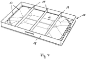
- FIG. 2 the container 1 is provided with an insert 10, which in FIG. 3 is shown individually in view from above.
- the support surface 11 of the insert 10 is designed cambered, wherein the crown is curved in the inserted state to the container opening upwards.
- the cambered area of the support surface 11 is surrounded by a recessed groove 12, in which at regular intervals mutually downwardly open holes 13 are provided.
- an edge region 14 extends laterally upwards, the outer edge 15 of which tightly abuts against the inside of the side walls 3 of the container 1 in the inserted state. Extensions are provided in diagonally opposite corner regions 16 of the edge region 14, in the surface of each of which a continuous bore 17 is provided as an engagement opening.
- the insert is surrounded by a downwardly directed, apron-like wall 18, which serves as a stand line on the bottom part 2 of the container and on the other hand as a spacer of the support surface 11 to the bottom part 2 of the container first
- 10 parallel ribs 19 are arranged on the underside of the insert, which are intended to prevent the down-flowed liquid in the space below the support surface 11 back and forth sloshes.
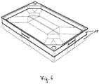
- FIG. 5 shows that the edges of the edge region 14 initially extend horizontally, in order to then pass into a bent edge 90 by 90 ° upwards.
- This upwardly bent edge 21 is slightly offset from the apron-like wall 18, so that as from FIG. 5 emerges, a sure and immovable Stacking several inserts 10 is possible. This also goes from the FIG. 6 out.
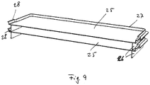
- the container 1 according to the invention is provided with a lid 25.
- this lid is shown in isolation. It consists of a flat rectangle, on the underside of which also a circumferential apron-like wall 26 is arranged, over which the side edges of the lid project.
- a circumferential rib 27 is provided, wherein the rib 27 and the skirt-like wall 26 are offset from each other such that the apron-like wall 26 can be received within the rib 27, so that a non-slip stacking a plurality of lid 25 is possible ,
- engagement recesses 28 are provided in the rib.
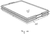
- FIG. 10 In the FIG. 10 are two lids stacked one above the other in perspective view.
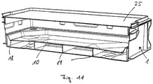
- FIG. 11 On average, an inventive container 1 with insert 10 and cover 25 is shown as it is assembled for transport.
Landscapes
- Engineering & Computer Science (AREA)
- Mechanical Engineering (AREA)
- Ceramic Engineering (AREA)
- Food Science & Technology (AREA)
- Packging For Living Organisms, Food Or Medicinal Products That Are Sensitive To Environmental Conditiond (AREA)
- Stackable Containers (AREA)
Description
- Die Erfindung betrifft einen Transportbehälter für den Transport von frischen Lebensmitteln, insbesondere Fisch, bestehend aus einem Bodenteil und von diesem Bodenteil aufragenden Seitenwänden, wobei die Oberkante der Seitenwände nach aussen geformt ist. Derartige Behälter sind beispielsweise aus der
DE 10 2010 018 894.8 , hier zum Transport von insbesondere Fleisch, bekannt. Der obere umgebogene Rand des Behälters dient als Auflager für einen zweiten identischen Behälter. - Ein derartiger Behälter ist in dieser einfachen Ausführung zum Transport von beispielsweise Fleisch, Gemüse oder Obst geeignet.
- Zum Transport von frischem, von Eisbruch bedecktem Fisch ist er in dieser Form nicht verwendbar.
- Aus der
DE 15 86 940 A1 ist ein Behälter zur Aufnahme und zum Transport von frischem Fisch beschrieben, der aus einem Aufnahmebehälter und einem in diesem Aufnahmebehälter eingesetzten Einsatz besteht, wobei der Einsatz in seinem oberen Bereich, nämlich dort wo das zum Kühlen benötigte Eis vorgesehen ist, über Öffnungen verfügt, durch die das schmelzende Eis in Ausnehmungen unterhalb des Einsatzes fließen kann. Die Fischflüssigkeit verbleibt jedoch im Behälter. - Auch aus der
EP 2 213 583 A1 ist ein Transportbehälter für Fisch bekannt, wobei dieser Behälter einen bombierten Boden aufweist, so dass rings um diese Bombierung herum Vertiefungen vorgesehen sind, in die schmelzendes Eis und Fischflüssigkeit fließen kann. Das Aufnahmevolumen dieser Vertiefung ist jedoch begrenzt, so dass nach einiger Zeit der Fisch in der Mischung aus Schmelzwasser und Fischflüssigkeit schwimmt. - Der Erfindung liegt daher die Aufgabe zugrunde, einen Behälter der eingangs genannten Art so auszubilden, dass auch der Transport von frischem Fisch unter hygienischen Bedingungen problemlos möglich ist.
- Die Erfindung löst diese Aufgabe gemäß dem kennzeichnenden Teil des Anspruchs 1.
- Die Bombierung des Einsatzes gewährleistet, dass beispielsweise tauendes Eis und der Saft des frischen Fisches in die umlaufende Rinne und von da über die Öffnungen in den unteren Bereich des Behälters ablaufen kann.
- Die nach unten gerichtete, schürzenartige Wand des Einsatzes gewährleistet, dass unterhalb des Einsatzes zum Boden des Behälters hin genügend Raum für das Flüssigkeitsgemisch vorhanden ist.
- Dabei liegt die Aussenkante des Einsatzes so dicht an der Innenseite der Seitenwände des Behälters an, dass beim Transport keine Flüssigkeit aus dem unteren Bereich wieder nach oben schwappen kann.
- Da die Behälter u. a. auf Förderanlagen bewegt werden, und es hier zu abrupten Stops und Wiederanfahren kommt, könnte das Tauwasser unterhalb des Einsatzes unkontrolliert hin und her schwappen und somit eine stabile Förderung der Behälter erschweren.
- Daher sieht der Anspruch 2 vor, dass an der Unterseite der bombierten Auflagefläche mehrere nach unten zum Behälterboden gerichtete Rippen vorgesehen sind, deren freie Unterkanten untereinander und mit der Unterkante der schürzenartigen Wand eine gemeinsame Ebene aufspannen und auf dem Bodenteil aufstehen.
- Die Unterteilung des Raumes unterhalb des Einsatzes durch diese in der Regel parallel zueinander angeordnten Rippen verhindert zum großen Teil das Hin- und Herschwappen des Tauwassers.
- Darüber hinaus hat diese Ausgestaltung der Rippen im Zusammenhang mit der schürzenartigen Wand des Einsatzes den Vorteil, dass die Einsätze an sich auch auf Förderanlagen problemlos bewegt werden können. Dabei ist gemäß Anspruch 3 vorgesehen, dass die Aussenkante des Randbereichs des Einsatzes senkrecht nach oben gerichtet ist, wobei im Querschnitt die schürzenartige Wand gegenüber der nach oben gerichteten Aussenkante um etwa die Dicke der schürzenartigen Wand ins Innere des Behälters versetzt ist.
- Diese Ausgestaltung gewährleistet es, dass mehrere Einsätze übereinander gestapelt werden können und dabei so seitlich gesichert sind, dass sie nicht gegeneinander verrutschen können.
- Gemäß Anspruch 4 ist vorgesehen, dass im Randbereich des Einsatzes Eingriffsöffnungen vorgesehen sind.
- Diese Eingriffsöffnungen sind beispielsweise in jeweils diagonal zueinander angeordneten Eckbereichen des Einsatzes vorgesehen, wobei diese Bereiche des Randes gegeneinander vorspringen. Somit ist es problemlos möglich, den Einsatz aus dem Behälter herauszuheben bzw. ihn in diesen einzusetzen.
- Gemäß Anspruch 5 ist vorgesehen, dass der Deckel ebenfalls eine ins Behälterinnere gerichtete umlaufende schürzenartige Wand aufweist, welche in einem Abstand von dem Deckelrand angeordnet ist, derart, dass der über die schürzenartige Wand hinausgehende Bereich des Deckels auf der Oberkante des Behälters aufliegt. Die ins Behälterinnere reichende umlaufende schürzenartige Wand stößt dabei mit ihrer Aussenseite an die Innenseite der Seitenwände des Behälters, so dass der Deckel praktisch spielfrei im Behälter angeordnet ist.
- Dadurch, dass gemäß Anspruch 5 auf der Oberseite des Deckels eine umlaufende, senkrecht nach oben gerichtete Rippe vorgesehen ist, wobei im Schnitt die umlaufende schürzenartige Wand um etwa die Dicke dieser schürzenartigen Wand gegenüber der auf der Oberseite angeordneten Rippe ins Behälterinnere versetzt ist, ist gewährleistet, dass auch mehrere Deckel übereinander gestapelt werden können und diese übereinander gestapelten Deckel unverschiebbar gegeneinander angeordnet sind.
- Gemäß Anspruch 7 ist vorgesehen, dass der Behälter im Bereich der nach oben vorstehenden umlaufenden Rippe mit Griffmulden versehen ist. Diese Griffmulden erleichtern die Handhabung des Deckels.
- Obwohl -wie bereits oben ausgeführt- der Deckel praktisch spielfrei auf dem Behälter sitzt, kann gemäß Anspruch 8 vorgesehen sein, dass der Deckel mit dem Behälterrand zusammenwirkende Arretiernasen aufweist.
- Schließlich ist gemäß Anspruch 9 noch vorgesehen, dass wie an sich bekannt in den Seitenwänden des Behälters ebenfalls Eingriffsöffnungen vorgesehen sind.
- Die Erfindung wird im folgenden anhand von Zeichnungen dargestellt und näher erläutert.
- Es zeigen:
- Figur 1
- in perspektivischer Darstellung einen Behälter an sich;
- Figur 2
- in perspektivischer Darstellung einen Behälter mit Einsatz;
- Figur 3
- perspektivische Darstellung des Einsatzes;
- Figur 4
- perspektivische Darstellung des Einsatzes von unten gesehen;
- Figur 5
- zwei übereinandergestapelte Einsätze im Schnitt;
- Figur 6
- zwei übereinandergestapelte Einsätze in perspektivischer Darstellung;
- Figur 7
- Behälter mit Deckel versehen;
- Figur 8
- Deckel in perspektivischer Darstellung von oben;
- Figur 9
- zwei übereinandergestapelte Deckel im Schnitt;
- Figur 10
- zwei übereinandergestapelte Deckel in perspektivischer Darstellung;
- Figur 11
- Schnitt durch einen Behälter mit Einsatz und aufgesetztem Deckel;
- In der
Figur 1 ist ein Transportbehälter dargestellt und allgemein mit dem Bezugszeichen 1 versehen. Er besteht aus einem Bodenteil 2 und von diesem Bodenteil konisch nach oben aufgeweiteten Seitenwänden 3. - Der Bodenteil 2 steht über die Seitenwände 3 nach aussen ab, so dass die Bodenfläche in ihrer Größe mit der von der Oberkante der Seitenwände aufgespannten Fläche übereinstimmt.
- Die Oberkanten 4 der Seitenwände 3 stehen ebenfalls nach aussen über die Seitenwände vor. Durch diese Ausgestaltung ist es möglich, mehrere identische Behälter 1 übereinander zu stapeln.
- In den Seitenwänden 3 sind Griffmulden bzw. Grifföffnungen 5 eingeformt. In den Eckbereichen 7 sind Verstärkungsrippen 8 angeformt, die die Stabilität mehrerer übereinander gestapelter beladener Behälter 1 erhöhen sollen.
- Der Bodenteil 2 kann eben ausgeführt sein. In der
Figur 1 ist jedoch dargestellt, dass der Bodenteil 2 leicht bombiert ausgestaltet ist, wie dies inFigur 11 dargestellt ist. - In der
Figur 2 ist der Behälter 1 mit einem Einsatz 10 versehen, der inFigur 3 einzeln dargestellt ist und zwar in Ansicht von oben. - Die Auflagefläche 11 des Einsatzes 10 ist bombiert ausgeführt, wobei die Bombierung im eingesetzten Zustand zur Behälteröffnung nach oben gewölbt ist. Der bombierte Bereich der Auflagefläche 11 ist umgeben von einer vertieften Rinne 12, in welcher in regelmäßigen Abständen zueinander nach unten offene Bohrungen 13 vorgesehen sind. Von der Rinne 12 geht seitlich nach oben ein Randbreich 14 ab, dessen Aussenkante 15 im eingesetzten Zustand an der Innenseite der Seitenwände 3 des Behälters 1 dicht anliegt. In einander diagonal gegenüberliegenden Eckbereichen 16 des Randbereiches 14 sind Erweiterungen vorgesehen, in deren Oberfläche jeweils eine durchgängige Bohrung 17 als Eingrifföffnung vorgesehen ist.
- Umgeben wird der Einsatz von einer nach unten gerichteten, schürzenartigen Wand 18, die zum einen als Standlinie auf dem Bodenteil 2 des Behälters dient und zum anderen als Abstandhalter der Auflagefläche 11 zum Bodenteil 2 des Behälters 1.
- Dies hat den Zweck, dass der beispielsweise frische Fisch, der von Eis bedeckt ist, so transportiert werden kann, dass geschmolzenes Eis und der Saft des frischen Fisches über die Öffnungen 13 in der Rinne 12 nach unten in einen relativ großen Raum ablaufen können.
- Wie aus
Figur 4 hervorgeht, sind an der Unterseite des Einsatzes 10 parallel zueinander verlaufende Rippen 19 angeordnet, die verhindern sollen, dass die nach unten abgeflossene Flüssigkeit in dem Raum unterhalb der Auflagefläche 11 hin- und herschwappt. Die Unterkanten der Rippen 19 spannen zusammen mit der Unterkante der schürzenartigen Wand 18 eine gemeinsame Ebene auf, so dass, wenn die Einsätze 10 getrennt vom Behälter auf Förderbändern transportiert werden müssen, ein sicherer Stand gewährleistet ist. - Aus
Figur 5 geht hervor, dass die Kanten des Randbereiches 14 zunächst horizontal verlaufen, um dann in einen um 90° nach oben gebogenen Rand 21 überzugehen. - Dieser nach oben gebogene Rand 21 ist gegenüber der schürzenartigen Wand 18 ein wenig versetzt, so dass wie aus
Figur 5 hervorgeht, ein sicheres und unverrückbares Übereinanderstapeln mehrerer Einsätze 10 möglich ist. Dies geht auch aus derFigur 6 hervor. - In der
Figur 7 ist der erfindungsgemäße Behälter 1 mit einem Deckel 25 versehen. - In der
Figur 8 ist dieser Deckel in Alleinstellung dargestellt. Er besteht aus einem ebenen Rechteck, an dessen Unterseite ebenfalls eine umlaufende schürzenartige Wand 26 angeordnet ist, über die die Seitenkanten des Deckels vorstehen. Auf der Oberseite des Deckels 25 ist eine umlaufende Rippe 27 vorgesehen, wobei die Rippe 27 und die schürzenartige Wand 26 derart zueinander versetzt sind, dass die schürzenartige Wand 26 innerhalb der Rippe 27 aufgenommen werden kann, so dass eine verrutschsichere Stapelung mehrerer Deckel 25 möglich ist. An den einander gegenüberliegenden Seiten des Deckels 25 sind in der Rippe 27 Eingriffsmulden 28 vorgesehen. - In der
Figur 10 sind in perspektivischer Darstellung zwei Deckel übereinander gestapelt. - In der
Figur 11 ist im Schnitt ein erfindungsgemäßer Behälter 1 mit Einsatz 10 und Deckel 25 dargestellt, wie er zum Transport zusammengestellt ist.
Claims (9)
- Behälter (1) für den Transport von frischen Lebensmitteln, insbesondere Fisch, bestehend aus einem Bodenteil (2) und von diesem Bodenteil aufragenden Seitenwänden, wobei die Oberkante der Seitenwände nach aussen geformt ist, wobei im Behälterinneren ein Einsatz (10) zur Aufnahme des zu transportierenden Gutes vorgesehen ist und der Behälter (1) mittels eines Deckels (25) verschließbar ist, dadurch gekennzeichnet, dass die Auflagefläche (11) des Einsatzes (10) bombiert ausgeführt und die Wölbung der Bombierung zur Behälteröffnung gerichtet ist und der bombierte Teil des Einsatzes (10) von einer vertieften Rinne (12) mit darin angeordneten Öffnungen (13) umgeben ist, und von der Rinne (12) ein seitlich nach oben gerichteter Randbereich (14) ausgeht, dessen Aussenkante (15) an der Innenseite der Seitenwände (3) des Behälters (1) anliegt und der Einsatz (10) von einer umlaufenden, nach unten gerichteten, schürzenartigen Wand (18) umgeben ist.
- Behälter nach Anspruch 1,
dadurch gekennzeichnet,
dass an der Unterseite der bombierten Auflagefläche (11) mehrere nach unten zum Behälterboden (2) gerichtete Rippen (19) vorgesehen sind, deren freie Unterkanten untereinander und mit der Unterkante der schürzenartigen Wand (18) eine gemeinsame Ebene aufspannen und auf dem Bodenteil (2) aufstehen. - Behälter nach Anspruch 1 oder 2,
dadurch gekennzeichnet,
dass die Aussenkante (15, 21) des Randbereichs (14) des Einsatzes (10) senkrecht nach oben gerichtet ist, wobei im Querschnitt die schürzenartige Wand (18) gegenüber der nach oben gerichteten Aussenkante (21) um etwa die Dicke der schürzenartigen Wand (18) ins Innere des Behälters (1) versetzt ist. - Behälter nach einem der Ansprüche 1 bis 3,
dadurch gekennzeichnet,
dass im Randbereich (16) des Einsatzes (10) Eingriffsöffnungen (17) vorgesehen sind. - Behälter nach einem der Ansprüche 1 bis 4,
dadurch gekennzeichnet,
dass der Deckel (25) ebenfalls eine ins Behälterinnere gerichtete umlaufende schürzenartige Wand (26) aufweist, welche in einem Abstand von dem Deckelrand angeordnet ist, derart, dass der über die schürzenartige Wand (26) hinausgehende Bereich des Deckels (25) auf der Oberkante des Behälters (1) aufliegt. - Behälter nach Anspruch 5,
dadurch gekennzeichnet,
dass auf der Oberseite des Deckels (25) eine umlaufende senkrecht nach oben gerichtete Rippe (27) vorgesehen ist, wobei im Querschnitt die umlaufende schürzenartige Wand (26) um etwa die Dicke dieser schürzenartigen Wand (26) gegenüber der auf der Oberseite angeordneten Rippe (27) ins Behälterinnere versetzt ist. - Behälter nach einem der Ansprüche 5 oder 6,
dadurch gekennzeichnet,
dass der Deckel (25) im Bereich der nach oben vorstehenden umlaufenden Rippe (27) mit Griffmulden (28) versehen ist. - Behälter nach einem der Ansprüche 5 bis 7,
dadurch gekennzeichnet,
dass am Deckel (25) mit dem Behälterrand zusammenwirkende Arretiernasen vorgesehen sind. - Behälter nach einem der Ansprüche 1 bis 8,
dadurch gekennzeichnet,
dass in den Seitenwänden (3) des Behälters (1) Eingriffsöffnungen (5) vorgesehen sind.
Priority Applications (1)
| Application Number | Priority Date | Filing Date | Title |
|---|---|---|---|
| PL14739060T PL3010836T3 (pl) | 2013-06-21 | 2014-06-18 | Pojemnik do transportu świeżych produktów spożywczych, w szczególności ryb |
Applications Claiming Priority (2)
| Application Number | Priority Date | Filing Date | Title |
|---|---|---|---|
| DE102013010382.7A DE102013010382B3 (de) | 2013-06-21 | 2013-06-21 | Transportbehälter für frische Lebensmittel, insbesondere Fisch |
| PCT/EP2014/062819 WO2014202662A1 (de) | 2013-06-21 | 2014-06-18 | Transportbehälter für frische lebensmittel, insbesondere fisch |
Publications (2)
| Publication Number | Publication Date |
|---|---|
| EP3010836A1 EP3010836A1 (de) | 2016-04-27 |
| EP3010836B1 true EP3010836B1 (de) | 2017-08-09 |
Family
ID=50879064
Family Applications (1)
| Application Number | Title | Priority Date | Filing Date |
|---|---|---|---|
| EP14739060.3A Active EP3010836B1 (de) | 2013-06-21 | 2014-06-18 | Transportbehälter für frische lebensmittel, insbesondere fisch |
Country Status (4)
| Country | Link |
|---|---|
| EP (1) | EP3010836B1 (de) |
| DE (1) | DE102013010382B3 (de) |
| PL (1) | PL3010836T3 (de) |
| WO (1) | WO2014202662A1 (de) |
Families Citing this family (1)
| Publication number | Priority date | Publication date | Assignee | Title |
|---|---|---|---|---|
| DE102018127567A1 (de) * | 2018-11-05 | 2020-05-07 | Werner Gasper | Verfahren zur Automatisierung von Warenströmen in einem Warenlager |
Family Cites Families (5)
| Publication number | Priority date | Publication date | Assignee | Title |
|---|---|---|---|---|
| DE1586936A1 (de) * | 1967-09-08 | 1970-08-20 | Schaefer Kg Fritz | Versandbehaelter fuer leicht verderbliche Lebensmittel |
| DE1980161U (de) * | 1967-09-16 | 1968-02-29 | Papierfabrik G M B H Vorm Brue | Behaelter mit fluessigkeitsdichter innenwanne. |
| DE20312305U1 (de) * | 2003-08-09 | 2003-12-04 | Neid, Oliver | Schalenförmiger Verpackungsbehälter für feuchtigkeitsabsondernde Lebensmittel |
| EP2213583A1 (de) * | 2009-01-29 | 2010-08-04 | Firma Paul Craemer GmbH | Transportbehälter für Fisch |
| DE102010018894A1 (de) * | 2010-04-30 | 2011-11-03 | Georg Utz Holding Ag | Transportbehälter zur Aufnahme von insbesondere Lebensmitteln |
-
2013
- 2013-06-21 DE DE102013010382.7A patent/DE102013010382B3/de not_active Expired - Fee Related
-
2014
- 2014-06-18 WO PCT/EP2014/062819 patent/WO2014202662A1/de active Application Filing
- 2014-06-18 EP EP14739060.3A patent/EP3010836B1/de active Active
- 2014-06-18 PL PL14739060T patent/PL3010836T3/pl unknown
Non-Patent Citations (1)
| Title |
|---|
| None * |
Also Published As
| Publication number | Publication date |
|---|---|
| DE102013010382B3 (de) | 2014-06-26 |
| PL3010836T3 (pl) | 2018-03-30 |
| EP3010836A1 (de) | 2016-04-27 |
| WO2014202662A1 (de) | 2014-12-24 |
Similar Documents
| Publication | Publication Date | Title |
|---|---|---|
| EP3790817B1 (de) | Stapelbarer behälter | |
| EP3640155B1 (de) | Vakuumisolationstransportbehälter für den temperaturgeführten transport | |
| WO2003008282A1 (de) | Schachtelbehälter | |
| DE202010013583U1 (de) | Transporteinheit für Großflaschen | |
| DE3737052C2 (de) | ||
| EP2024242B1 (de) | Systemkiste insbesondere für den transport von frischem fisch | |
| EP3010836B1 (de) | Transportbehälter für frische lebensmittel, insbesondere fisch | |
| DE2433734A1 (de) | Transportbehaelter aus kunststoff, insbesondere fisch-transportbehaelter | |
| DE4103333A1 (de) | Transportbehaelter | |
| CH712478A1 (de) | Deckel für einen Teebehälter. | |
| DE2555321A1 (de) | Zum aufbewahren und servieren geeigneter mit abdichtendem deckel versehener behaelter | |
| DE60001994T2 (de) | System von identischen modularen und aufeinander stapelbaren Behältern, insbesondere für Nahrungsmittel | |
| DE4308861A1 (de) | Stapelbarer Behälter mit Deckel | |
| DE3718504A1 (de) | Transportbehaelter | |
| EP0839726B1 (de) | Isolierbehälter | |
| DE69100527T2 (de) | Behälter für Fische. | |
| DE7635978U1 (de) | Frischkaese | |
| DE202011102579U1 (de) | Verpackung für Lebensmittel, insbesondere für Frischkäseprodukte, Pasteten, Brotaufstriche und dgl. | |
| DE3515771C2 (de) | ||
| EP2540639B1 (de) | Verpackung für Lebensmittel, insbesondere für Frischkäseprodukte, Pasteten, Brotaufstriche und dgl. | |
| DE202011102578U1 (de) | Verpackung für Lebensmittel, insbesondere für Frischkäseprodukte, Pasteten, Brotaufstriche und dgl. | |
| DE29702661U1 (de) | Stapelbehälter | |
| DE3134388A1 (de) | "drehstapelbehaelter" | |
| DE102015110789B4 (de) | Stapelbehälter | |
| DE4314920A1 (de) | Mit einem abnehmbaren Deckel versehener Behälter |
Legal Events
| Date | Code | Title | Description |
|---|---|---|---|
| PUAI | Public reference made under article 153(3) epc to a published international application that has entered the european phase |
Free format text: ORIGINAL CODE: 0009012 |
|
| 17P | Request for examination filed |
Effective date: 20160121 |
|
| AK | Designated contracting states |
Kind code of ref document: A1 Designated state(s): AL AT BE BG CH CY CZ DE DK EE ES FI FR GB GR HR HU IE IS IT LI LT LU LV MC MK MT NL NO PL PT RO RS SE SI SK SM TR |
|
| AX | Request for extension of the european patent |
Extension state: BA ME |
|
| DAX | Request for extension of the european patent (deleted) | ||
| GRAP | Despatch of communication of intention to grant a patent |
Free format text: ORIGINAL CODE: EPIDOSNIGR1 |
|
| INTG | Intention to grant announced |
Effective date: 20170207 |
|
| GRAS | Grant fee paid |
Free format text: ORIGINAL CODE: EPIDOSNIGR3 |
|
| GRAA | (expected) grant |
Free format text: ORIGINAL CODE: 0009210 |
|
| AK | Designated contracting states |
Kind code of ref document: B1 Designated state(s): AL AT BE BG CH CY CZ DE DK EE ES FI FR GB GR HR HU IE IS IT LI LT LU LV MC MK MT NL NO PL PT RO RS SE SI SK SM TR |
|
| REG | Reference to a national code |
Ref country code: GB Ref legal event code: FG4D Free format text: NOT ENGLISH |
|
| REG | Reference to a national code |
Ref country code: CH Ref legal event code: EP Ref country code: AT Ref legal event code: REF Ref document number: 916548 Country of ref document: AT Kind code of ref document: T Effective date: 20170815 |
|
| REG | Reference to a national code |
Ref country code: IE Ref legal event code: FG4D Free format text: LANGUAGE OF EP DOCUMENT: GERMAN |
|
| REG | Reference to a national code |
Ref country code: DE Ref legal event code: R096 Ref document number: 502014004979 Country of ref document: DE |
|
| REG | Reference to a national code |
Ref country code: NL Ref legal event code: FP |
|
| REG | Reference to a national code |
Ref country code: LT Ref legal event code: MG4D |
|
| PG25 | Lapsed in a contracting state [announced via postgrant information from national office to epo] |
Ref country code: HR Free format text: LAPSE BECAUSE OF FAILURE TO SUBMIT A TRANSLATION OF THE DESCRIPTION OR TO PAY THE FEE WITHIN THE PRESCRIBED TIME-LIMIT Effective date: 20170809 Ref country code: LT Free format text: LAPSE BECAUSE OF FAILURE TO SUBMIT A TRANSLATION OF THE DESCRIPTION OR TO PAY THE FEE WITHIN THE PRESCRIBED TIME-LIMIT Effective date: 20170809 Ref country code: SE Free format text: LAPSE BECAUSE OF FAILURE TO SUBMIT A TRANSLATION OF THE DESCRIPTION OR TO PAY THE FEE WITHIN THE PRESCRIBED TIME-LIMIT Effective date: 20170809 Ref country code: NO Free format text: LAPSE BECAUSE OF FAILURE TO SUBMIT A TRANSLATION OF THE DESCRIPTION OR TO PAY THE FEE WITHIN THE PRESCRIBED TIME-LIMIT Effective date: 20171109 Ref country code: FI Free format text: LAPSE BECAUSE OF FAILURE TO SUBMIT A TRANSLATION OF THE DESCRIPTION OR TO PAY THE FEE WITHIN THE PRESCRIBED TIME-LIMIT Effective date: 20170809 |
|
| PG25 | Lapsed in a contracting state [announced via postgrant information from national office to epo] |
Ref country code: RS Free format text: LAPSE BECAUSE OF FAILURE TO SUBMIT A TRANSLATION OF THE DESCRIPTION OR TO PAY THE FEE WITHIN THE PRESCRIBED TIME-LIMIT Effective date: 20170809 Ref country code: BG Free format text: LAPSE BECAUSE OF FAILURE TO SUBMIT A TRANSLATION OF THE DESCRIPTION OR TO PAY THE FEE WITHIN THE PRESCRIBED TIME-LIMIT Effective date: 20171109 Ref country code: LV Free format text: LAPSE BECAUSE OF FAILURE TO SUBMIT A TRANSLATION OF THE DESCRIPTION OR TO PAY THE FEE WITHIN THE PRESCRIBED TIME-LIMIT Effective date: 20170809 Ref country code: ES Free format text: LAPSE BECAUSE OF FAILURE TO SUBMIT A TRANSLATION OF THE DESCRIPTION OR TO PAY THE FEE WITHIN THE PRESCRIBED TIME-LIMIT Effective date: 20170809 Ref country code: IS Free format text: LAPSE BECAUSE OF FAILURE TO SUBMIT A TRANSLATION OF THE DESCRIPTION OR TO PAY THE FEE WITHIN THE PRESCRIBED TIME-LIMIT Effective date: 20171209 Ref country code: GR Free format text: LAPSE BECAUSE OF FAILURE TO SUBMIT A TRANSLATION OF THE DESCRIPTION OR TO PAY THE FEE WITHIN THE PRESCRIBED TIME-LIMIT Effective date: 20171110 |
|
| PG25 | Lapsed in a contracting state [announced via postgrant information from national office to epo] |
Ref country code: DK Free format text: LAPSE BECAUSE OF FAILURE TO SUBMIT A TRANSLATION OF THE DESCRIPTION OR TO PAY THE FEE WITHIN THE PRESCRIBED TIME-LIMIT Effective date: 20170809 Ref country code: CZ Free format text: LAPSE BECAUSE OF FAILURE TO SUBMIT A TRANSLATION OF THE DESCRIPTION OR TO PAY THE FEE WITHIN THE PRESCRIBED TIME-LIMIT Effective date: 20170809 Ref country code: RO Free format text: LAPSE BECAUSE OF FAILURE TO SUBMIT A TRANSLATION OF THE DESCRIPTION OR TO PAY THE FEE WITHIN THE PRESCRIBED TIME-LIMIT Effective date: 20170809 |
|
| REG | Reference to a national code |
Ref country code: DE Ref legal event code: R097 Ref document number: 502014004979 Country of ref document: DE |
|
| PG25 | Lapsed in a contracting state [announced via postgrant information from national office to epo] |
Ref country code: SM Free format text: LAPSE BECAUSE OF FAILURE TO SUBMIT A TRANSLATION OF THE DESCRIPTION OR TO PAY THE FEE WITHIN THE PRESCRIBED TIME-LIMIT Effective date: 20170809 Ref country code: SK Free format text: LAPSE BECAUSE OF FAILURE TO SUBMIT A TRANSLATION OF THE DESCRIPTION OR TO PAY THE FEE WITHIN THE PRESCRIBED TIME-LIMIT Effective date: 20170809 Ref country code: IT Free format text: LAPSE BECAUSE OF FAILURE TO SUBMIT A TRANSLATION OF THE DESCRIPTION OR TO PAY THE FEE WITHIN THE PRESCRIBED TIME-LIMIT Effective date: 20170809 Ref country code: EE Free format text: LAPSE BECAUSE OF FAILURE TO SUBMIT A TRANSLATION OF THE DESCRIPTION OR TO PAY THE FEE WITHIN THE PRESCRIBED TIME-LIMIT Effective date: 20170809 |
|
| PLBE | No opposition filed within time limit |
Free format text: ORIGINAL CODE: 0009261 |
|
| STAA | Information on the status of an ep patent application or granted ep patent |
Free format text: STATUS: NO OPPOSITION FILED WITHIN TIME LIMIT |
|
| REG | Reference to a national code |
Ref country code: FR Ref legal event code: PLFP Year of fee payment: 5 |
|
| 26N | No opposition filed |
Effective date: 20180511 |
|
| PG25 | Lapsed in a contracting state [announced via postgrant information from national office to epo] |
Ref country code: SI Free format text: LAPSE BECAUSE OF FAILURE TO SUBMIT A TRANSLATION OF THE DESCRIPTION OR TO PAY THE FEE WITHIN THE PRESCRIBED TIME-LIMIT Effective date: 20170809 |
|
| PG25 | Lapsed in a contracting state [announced via postgrant information from national office to epo] |
Ref country code: MT Free format text: LAPSE BECAUSE OF FAILURE TO SUBMIT A TRANSLATION OF THE DESCRIPTION OR TO PAY THE FEE WITHIN THE PRESCRIBED TIME-LIMIT Effective date: 20170809 |
|
| GBPC | Gb: european patent ceased through non-payment of renewal fee |
Effective date: 20180618 |
|
| REG | Reference to a national code |
Ref country code: IE Ref legal event code: MM4A |
|
| PG25 | Lapsed in a contracting state [announced via postgrant information from national office to epo] |
Ref country code: LU Free format text: LAPSE BECAUSE OF NON-PAYMENT OF DUE FEES Effective date: 20180618 Ref country code: MC Free format text: LAPSE BECAUSE OF FAILURE TO SUBMIT A TRANSLATION OF THE DESCRIPTION OR TO PAY THE FEE WITHIN THE PRESCRIBED TIME-LIMIT Effective date: 20170809 |
|
| PG25 | Lapsed in a contracting state [announced via postgrant information from national office to epo] |
Ref country code: GB Free format text: LAPSE BECAUSE OF NON-PAYMENT OF DUE FEES Effective date: 20180618 Ref country code: IE Free format text: LAPSE BECAUSE OF NON-PAYMENT OF DUE FEES Effective date: 20180618 |
|
| PG25 | Lapsed in a contracting state [announced via postgrant information from national office to epo] |
Ref country code: TR Free format text: LAPSE BECAUSE OF FAILURE TO SUBMIT A TRANSLATION OF THE DESCRIPTION OR TO PAY THE FEE WITHIN THE PRESCRIBED TIME-LIMIT Effective date: 20170809 |
|
| PG25 | Lapsed in a contracting state [announced via postgrant information from national office to epo] |
Ref country code: PT Free format text: LAPSE BECAUSE OF FAILURE TO SUBMIT A TRANSLATION OF THE DESCRIPTION OR TO PAY THE FEE WITHIN THE PRESCRIBED TIME-LIMIT Effective date: 20170809 |
|
| PG25 | Lapsed in a contracting state [announced via postgrant information from national office to epo] |
Ref country code: CY Free format text: LAPSE BECAUSE OF FAILURE TO SUBMIT A TRANSLATION OF THE DESCRIPTION OR TO PAY THE FEE WITHIN THE PRESCRIBED TIME-LIMIT Effective date: 20170809 Ref country code: HU Free format text: LAPSE BECAUSE OF FAILURE TO SUBMIT A TRANSLATION OF THE DESCRIPTION OR TO PAY THE FEE WITHIN THE PRESCRIBED TIME-LIMIT; INVALID AB INITIO Effective date: 20140618 Ref country code: MK Free format text: LAPSE BECAUSE OF NON-PAYMENT OF DUE FEES Effective date: 20170809 |
|
| PG25 | Lapsed in a contracting state [announced via postgrant information from national office to epo] |
Ref country code: AL Free format text: LAPSE BECAUSE OF FAILURE TO SUBMIT A TRANSLATION OF THE DESCRIPTION OR TO PAY THE FEE WITHIN THE PRESCRIBED TIME-LIMIT Effective date: 20170809 |
|
| PGFP | Annual fee paid to national office [announced via postgrant information from national office to epo] |
Ref country code: CH Payment date: 20230702 Year of fee payment: 10 |
|
| PGFP | Annual fee paid to national office [announced via postgrant information from national office to epo] |
Ref country code: DE Payment date: 20240619 Year of fee payment: 11 |
|
| PGFP | Annual fee paid to national office [announced via postgrant information from national office to epo] |
Ref country code: NL Payment date: 20240619 Year of fee payment: 11 |
|
| PGFP | Annual fee paid to national office [announced via postgrant information from national office to epo] |
Ref country code: AT Payment date: 20240620 Year of fee payment: 11 |
|
| PGFP | Annual fee paid to national office [announced via postgrant information from national office to epo] |
Ref country code: FR Payment date: 20240628 Year of fee payment: 11 |
|
| PGFP | Annual fee paid to national office [announced via postgrant information from national office to epo] |
Ref country code: PL Payment date: 20240614 Year of fee payment: 11 |
|
| PGFP | Annual fee paid to national office [announced via postgrant information from national office to epo] |
Ref country code: BE Payment date: 20240619 Year of fee payment: 11 |