EP3789337A1 - Rotierender beweglicher körper für drahtseil - Google Patents
Rotierender beweglicher körper für drahtseil Download PDFInfo
- Publication number
- EP3789337A1 EP3789337A1 EP19870338.1A EP19870338A EP3789337A1 EP 3789337 A1 EP3789337 A1 EP 3789337A1 EP 19870338 A EP19870338 A EP 19870338A EP 3789337 A1 EP3789337 A1 EP 3789337A1
- Authority
- EP
- European Patent Office
- Prior art keywords
- wire rope
- rope
- rotating
- movable body
- portions
- Prior art date
- Legal status (The legal status is an assumption and is not a legal conclusion. Google has not performed a legal analysis and makes no representation as to the accuracy of the status listed.)
- Pending
Links
Images








Classifications
-
- D—TEXTILES; PAPER
- D07—ROPES; CABLES OTHER THAN ELECTRIC
- D07B—ROPES OR CABLES IN GENERAL
- D07B7/00—Details of, or auxiliary devices incorporated in, rope- or cable-making machines; Auxiliary apparatus associated with such machines
- D07B7/16—Auxiliary apparatus
-
- F—MECHANICAL ENGINEERING; LIGHTING; HEATING; WEAPONS; BLASTING
- F16—ENGINEERING ELEMENTS AND UNITS; GENERAL MEASURES FOR PRODUCING AND MAINTAINING EFFECTIVE FUNCTIONING OF MACHINES OR INSTALLATIONS; THERMAL INSULATION IN GENERAL
- F16M—FRAMES, CASINGS OR BEDS OF ENGINES, MACHINES OR APPARATUS, NOT SPECIFIC TO ENGINES, MACHINES OR APPARATUS PROVIDED FOR ELSEWHERE; STANDS; SUPPORTS
- F16M13/00—Other supports for positioning apparatus or articles; Means for steadying hand-held apparatus or articles
- F16M13/02—Other supports for positioning apparatus or articles; Means for steadying hand-held apparatus or articles for supporting on, or attaching to, an object, e.g. tree, gate, window-frame, cycle
- F16M13/022—Other supports for positioning apparatus or articles; Means for steadying hand-held apparatus or articles for supporting on, or attaching to, an object, e.g. tree, gate, window-frame, cycle repositionable
-
- G—PHYSICS
- G01—MEASURING; TESTING
- G01B—MEASURING LENGTH, THICKNESS OR SIMILAR LINEAR DIMENSIONS; MEASURING ANGLES; MEASURING AREAS; MEASURING IRREGULARITIES OF SURFACES OR CONTOURS
- G01B5/00—Measuring arrangements characterised by the use of mechanical techniques
- G01B5/20—Measuring arrangements characterised by the use of mechanical techniques for measuring contours or curvatures
-
- B—PERFORMING OPERATIONS; TRANSPORTING
- B66—HOISTING; LIFTING; HAULING
- B66B—ELEVATORS; ESCALATORS OR MOVING WALKWAYS
- B66B7/00—Other common features of elevators
- B66B7/12—Checking, lubricating, or cleaning means for ropes, cables or guides
- B66B7/1207—Checking means
- B66B7/1215—Checking means specially adapted for ropes or cables
-
- B—PERFORMING OPERATIONS; TRANSPORTING
- B66—HOISTING; LIFTING; HAULING
- B66B—ELEVATORS; ESCALATORS OR MOVING WALKWAYS
- B66B7/00—Other common features of elevators
- B66B7/12—Checking, lubricating, or cleaning means for ropes, cables or guides
- B66B7/1207—Checking means
- B66B7/1215—Checking means specially adapted for ropes or cables
- B66B7/1238—Checking means specially adapted for ropes or cables by optical techniques
-
- B—PERFORMING OPERATIONS; TRANSPORTING
- B66—HOISTING; LIFTING; HAULING
- B66B—ELEVATORS; ESCALATORS OR MOVING WALKWAYS
- B66B7/00—Other common features of elevators
- B66B7/12—Checking, lubricating, or cleaning means for ropes, cables or guides
- B66B7/1276—Cleaning means
- B66B7/1284—Cleaning means specially adapted for ropes or cables
-
- D—TEXTILES; PAPER
- D07—ROPES; CABLES OTHER THAN ELECTRIC
- D07B—ROPES OR CABLES IN GENERAL
- D07B1/00—Constructional features of ropes or cables
- D07B1/14—Ropes or cables with incorporated auxiliary elements, e.g. for marking, extending throughout the length of the rope or cable
- D07B1/145—Ropes or cables with incorporated auxiliary elements, e.g. for marking, extending throughout the length of the rope or cable comprising elements for indicating or detecting the rope or cable status
Definitions
- This invention relates to a rotating movable body for a wire rope, which is used on a wire rope.
- a spiral-shaped portion that follows the shape of the wire rope is formed on an inner peripheral surface of a tubular member.
- This type of rotating movable body for a wire rope moves while rotating around the wire rope.
- the wire rope can be cleaned, and the wire rope can be inspected for deformations such as kinks occurring in the strands of the wire rope.
- a method of measuring leakage flux from the wire rope using a flaw detector may be employed to inspect the wire rope for deformations, but since a flaw detector is expensive, the cost of the operation to inspect the wire rope increases.
- This invention has been designed to solve these problems, and an object thereof is to provide a rotating movable body for a wire rope, with which reductions in processing labor and weight can be achieved and a wire rope inspection operation can be performed at low cost.
- a rotating movable body for a wire rope includes a rotating portion through the interior of which a wire rope passes, the wire rope being formed by twisting together a plurality of strands, and at least two rope engaging portions provided on the rotating portion so as to engage with parts of an outer shape of the wire rope, wherein the at least two rope engaging portions are arranged at a predetermined interval in an extension direction of the wire rope, and in a state where each of the plurality of strands is in contact with one of the at least two rope engaging portions, the rotating portion moves in the extension direction of the wire rope and rotates so as to follow the twist of the strands.
- the rope engaging portions of the rotating movable body for a wire rope may include rotary plates respectively formed with rope passing holes through which the wire rope passes, at least one rope-engaging recessed portion may be formed in each of the rope passing holes, and the rope-engaging recessed portion may engage with two adjacent strands among the plurality of strands of the wire rope.
- two rope-engaging recessed portions may be formed in the rope passing hole in each of the rotary plates.
- the rope engaging portions may include rope-engaging projecting portions that project inwardly from the rotating portion, and each of the rope-engaging projecting portions may engage with a groove between two adjacent strands among the plurality of strands of the wire rope.
- a strand contacting portion that comes into contact with the strands of the wire rope by surface contact may be provided on the inside of the rotating portion.
- a needle sensor that comes into contact with the strands of the wire rope and detects variation in a surface shape of the wire rope may be provided on the rotating portion.
- the rotating portion may include at least two tubular case portions that are arranged in the extension direction of the wire rope and capable of rotating relative to each other, and the rope engaging portions may be provided on the insides of the respective case portions.
- the rope engaging portions may be formed of elastic bodies.
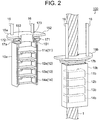
- a rotating movable body 100 for a wire rope which is attached to a wire rope 1, includes a rotating portion 2 through the interior of which the wire rope 1 passes, a connecting portion 15 attached to an upper end of the rotating portion 2, and four rod-shaped pulled portions 16 that are coupled to the rotating portion 2 via the connecting portion 15.
- the rotating portion 2 is capable of rotating about the wire rope 1. Note that the rotational center of the rotating portion 2 is set as a rotary axis X.
- the rotating portion 2 includes a substantially rectangular parallelepiped-shaped tubular case portion 10.
- the wire rope 1 passes through the interior of the case portion 10 of the rotating portion 2.
- the case portion 10 of the rotating portion 2 is divided into two parts, namely a first case portion 10a and a second case portion 10b, along the direction of the rotary axis X.
- each of the rotary plates 11, 12, 13, 14 is similarly divided into two parts in the direction of the rotary axis X of the rotating portion 2.
- First rotary plates 11a, 12a, 13a, 14a constituting one of the two divided parts of the respective rotary plates 11, 12, 13, 14 are fixed to the inside of the first case portion 10a, and second rotary plates 11b, 12b, 13b, 14b respectively constituting the other part are fixed to the inside of the second case portion 10b.
- the rotary plates 11, 12, 13, 14 constitute rope engaging portions. Further, the rotary plates 11, 12, 13, 14 are formed of elastic bodies made of a steel material, carbon fiber, resin, or the like.
- an attachment portion 17 attached to the upper end of the case portion 10 is divided into a first attachment portion 17a and a second attachment portion 17b in the direction of the rotary axis X of the rotating portion 2.
- the first attachment portion 17a is fixed to the upper end of the first case portion 10a
- the second attachment portion 17b is fixed to the upper end of the second case portion 10b.
- a convex portion 171 is formed on one end surface of the first attachment portion 17a, which is curved into a semicircular shape, and a concave portion 172 is formed in the other end surface.
- a convex portion (not shown) having a similar shape to the convex portion 171 is formed on one end surface of the second attachment portion 17b, which is curved into a semicircular shape, and a concave portion (not shown) having a similar shape to the concave portion 172 is formed in the other end surface.
- the connecting portion 15 is attached to the attachment portion 17.
- the connecting portion 15 includes a cylindrical portion 151 and a flange portion 152 provided on an upper end of the cylindrical portion 151.
- a substantially annular projecting engagement portion 153 is formed on an outer peripheral surface of the cylindrical portion 151.
- the cylindrical portion 151 of the connecting portion 15 is fitted to the inside of the attachment portion 17, and the projecting engagement portion 153 on the cylindrical portion 151 of the connecting portion 15 is fitted into the engagement groove 173 in the attachment portion 17.
- a bearing or a clamp (not shown) is provided between the attachment portion 17 and the connecting portion 15.
- the connecting portion 15 is thus attached to the attachment portion 17 so as to be capable of rotating relative thereto. Moreover, the connecting portion 15 is divided into a first connecting portion 15a and a second connecting portion 15b in the direction of the rotary axis X of the rotating portion 2. End portions of two of the pulled portions 16 are attached to each of the respective flange portions 152 of the first connecting portion 15a and the second connecting portion 15b.
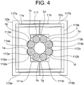
- the wire rope 1 is formed by twisting together eight strands 1a, 1b, 1c, 1d, 1e, 1f, 1g, 1h.
- a cutout 111a is formed in one side of the first rotary plate 11a of the rotary plate 11.
- a rope-engaging recessed portion 112a capable of engaging with the strands 1a, 1b of the wire rope 1 is formed in the cutout 111a of the first rotary plate 11a.
- the rope-engaging recessed portion 112a includes two semicircular portions 113a that correspond to respective outer shapes of the strands 1a, 1b of the wire rope 1.
- a projecting part 114a formed between the two semicircular portions 113a engages with a groove between the strands 1a, 1b of the wire rope 1.
- a cutout 111b is formed in one side of the second rotary plate 11b.
- a rope-engaging recessed portion 112b capable of engaging with the strands 1e, 1f of the wire rope 1 is formed in the cutout 111b of the second rotary plate 11b.
- the rope-engaging recessed portion 112b includes two semicircular portions 113b that correspond to respective outer shapes of the strands 1e, 1f of the wire rope 1. Further, a projecting part 114b formed between the two semicircular portions 113b engages with a groove between the strands 1e, 1f of the wire rope 1.
- bent portions 115a, 116a, 117a that are bent downward are provided on the three sides of the first rotary plate 11a other than the side provided with the cutout 111a.
- bent portions 115b, 116b, 117b that are bent downward are provided on the three sides of the second rotary plate 11b other than the side provided with the cutout 111b. Accordingly, the downward-bent bent portions 115a, 115b, 116a, 116b, 117a, 117b are provided on the four sides of the rotary plate 11.
- first rotary plates 12a, 13a, 14a and the second rotary plates 12b, 13b, 14b of the rotary plates 12, 13, 14 disposed on the lower side of the rotary plate 11 have similar structures to the first rotary plate 11a and the second rotary plate 11b of the rotary plate 11.
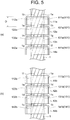
- cutouts 121a, 131a, 141a are formed in the first rotary plates 12a, 13a, 14a of the rotary plates 12, 13, 14. Further, rope-engaging recessed portions 122a, 132a, 142a are provided in the cutouts 121a, 131a, 141a.
- the rope-engaging recessed portion 112a of the first rotary plate 11a engages with the outer shapes of the strands 1a, 1b of the wire rope 1 and the groove between the strands 1a, 1b.
- the rope-engaging recessed portion 122a of the first rotary plate 12a engages with the outer shapes of the strands 1h, 1a of the wire rope 1 and the groove between the strands 1h, 1a.
- the rope-engaging recessed portion 132a of the first rotary plate 13a engages with the outer shapes of the strands 1g, 1h of the wire rope 1 and the groove between the strands 1g, 1h.
- the rope-engaging recessed portion 142a of the first rotary plate 14a engages with the outer shapes of the strands 1f, 1g of the wire rope 1 and the groove between the strands 1f, 1g.
- cutouts 121b, 131b, 141b are formed in the second rotary plates 12b, 13b, 14b. Further, rope-engaging recessed portions 122b, 132b, 142b are provided in the cutouts 121b, 131b, 141b. The rope-engaging recessed portion 112b of the second rotary plate 11b engages with the outer shapes of the strands 1e, 1f of the wire rope 1 and the groove between the strands 1e, 1f.
- the rope-engaging recessed portion 122b of the second rotary plate 12b engages with the outer shapes of the strands 1d, 1e of the wire rope 1 and the groove between the strands 1d, 1e.
- the rope-engaging recessed portion 132b of the second rotary plate 13b engages with the outer shapes of the strands 1c, 1d of the wire rope 1 and the groove between the strands 1c, 1d.
- the rope-engaging recessed portion 142b of the second rotary plate 14b engages with the outer shapes of the strands 1b, 1c of the wire rope 1 and the groove between the strands 1b, 1c.
- cutouts 121a, 131a, 141a in the first rotary plates 12a, 13a, 14a and the cutouts 121b, 131b, 141b in the second rotary plates 12b, 13b, 14b respectively constitute rope passing holes 121, 131, 141 in the rotary plates 12, 13, 14.
- bent portions that are bent downward are provided on the four sides of each of the rotary plates 12, 13, 14 constituted by the first rotary plates 12a, 13a, 14a and the second rotary plates 12b, 13b, 14b.
- the rotating movable body 100 for a wire rope is divided into two parts in the direction of the rotary axis X and then joined together so as to sandwich the wire rope 1.
- the four rotary plates 11, 12, 13, 14 are arranged at the predetermined interval D in the extension direction of the wire rope 1. Further, the rope-engaging recessed portions 112a, 112b, 122a, 122b, 132a, 132b, 142a, 142b formed in the four rotary plates 11, 12, 13, 14 each engage with a part of the outer shape of the wire rope 1.
- the rotating movable body 100 for a wire rope can be manufactured by processing the rotary plates 11, 12, 13, 14 serving as the rope engaging portions one at a time in alignment with parts of the outer shape of the wire rope 1.
- the rotating movable body 100 for a wire rope can be manufactured more easily than when a spiral-shaped irregularity that follows the twist of the strands 1a to 1h of the wire rope 1 is formed on the inner peripheral surface of a single tubular member. Moreover, the amount of processing labor is reduced, and therefore the manufacturing cost of the rotating movable body 100 for a wire rope can be suppressed. Furthermore, the rope engaging portions are constituted by the four thin rotary plates 11, 12, 13, 14, and therefore the weight of the rotating movable body 100 for a wire rope can be reduced. In addition, by using the rotating movable body 100 for a wire rope, the cost of an operation to inspect the wire rope 1 for deformations can be suppressed in comparison with a conventional flaw detector that inspects the wire rope 1 using leakage flux.
- the rope-engaging recessed portions 112a, 112b, 122a, 122b, 132a, 132b, 142a, 142b engage with two adjacent strands among the eight strands 1a to 1h of the wire rope 1.
- the rotary plates 11, 12, 13, 14 can engage with the wire rope 1 more reliably.
- the number of rotary plates 11, 12, 13, 14 serving as the rope engaging portions can be set at four, i.e. half the number of strands.
- the number of components of the rotating movable body 100 for a wire rope and the size and weight of the rotating movable body 100 for a wire rope can be reduced.
- the rotary plates 11, 12, 13, 14 can be processed more easily.
- Figs. 6 to 8 show a configuration of a rotating movable body 200 for a wire rope according to a second embodiment of this invention. Note that identical symbols to the reference symbols in Figs. 1 to 5 denote identical or similar constituent elements, and therefore detailed description thereof has been omitted.
- the rotating movable body 200 for a wire rope includes a rotating portion 202 through the interior of which the wire rope 1 passes.
- the rotating portion 202 includes four substantially cylindrical case portions 21, 22, 23, 24 in the extension direction of the wire rope 1.
- a substantially annular band-shaped convex portion 211 is formed on an outer periphery of an upper end of the case portion 21. Further, a groove portion 212 is formed on an inner peripheral side of the convex portion 211. Furthermore, a flange portion 213 is formed on an outer periphery of a lower end of the case portion 21.
- case portions 22, 23, 24 disposed on the lower side of the case portion 21 have a similar structure to the case portion 21. More specifically, the case portions 22, 23, 24 respectively include convex portions 221, 231, 241, groove portions 222, 232, 242, and flange portions 223, 233, 243 having similar shapes to the convex portion 211, the groove portion 212, and the flange portion 213.
- the projecting engagement portion 153 of the connecting portion 15 engages with the groove portion 212 in the case portion 21. Further, the flange portion 213 of the case portion 21 engages with the groove portion 222 in the case portion 22. Further, the flange portion 223 of the case portion 22 engages with the groove portion 232 in the case portion 23. Further, the flange portion 233 of the case portion 23 engages with the groove portion 242 in the case portion 24.
- the case portions 21, 22, 23, 24 are capable of rotating relative to each other.
- bearings or clamps are provided in the respective coupling parts between the connecting portion 15 and the case portions 21, 22, 23, 24.
- a first case portion 21a serving as one part of the case portion 21 divided into two parts includes a rotary plate 214 on the inside thereof.
- a cutout 214a constituing a rope passing hole through which the wire rope 1 passes is formed in the rotary plate 214.
- two rope-engaging recessed portions 214b that engage with two adjacent strands, among the eight strands 1a to 1h of the wire rope 1, and the groove between the strands are formed in the cutout 214a.
- the other part of the case portion 21 divided into two parts has a similar shape to the first case portion 21a. More specifically, two rope-engaging recessed portions 214b are formed in the rotary plate 214 provided in the interior of the case portion 21.
- case portions 22, 23, 24 disposed on the lower side of the case portion 21 include rotary plates 224, 234, 244 having a similar shape to the rotary plate 214 provided on the inside of the case portion 21.
- each of the rotary plates 224, 234, 244 is formed with the cutout 214a and the rope-engaging recessed portions 214b that engage with two adjacent strands and the groove between the strands.
- the rotary plates 214, 224, 234, 244 respectively constitute rope engaging portions that engage with parts of the outer shape of the wire rope 1. Further, the rotary plates 214, 224, 234, 244 are arranged at predetermined intervals in the extension direction of the wire rope 1.
- the connecting portion 15 which is divided into two parts and case portions 21, 22, 23, 24 are joined together so as to sandwich the wire rope 1.
- the case portions 21, 22, 23, 24 are disposed so that the rope-engaging recessed portions 214b formed in the rotary plates 214, 224, 234, 244 engage with all of the grooves provided between the strands 1a to 1h.
- each of the strands 1a to 1h is in contact with one of the rope-engaging recessed portions 214b of the rotary plates 214, 224, 234, 244.
- the rotating movable body 200 for a wire rope is operated, the pulled portions 16 are pulled upward by a motor (not shown). Accordingly, the case portions 21, 22, 23, 24 of the rotating portion 202 move in the extension direction of the wire rope 1 while the pulled portions 16 are pulled, as indicated by the arrow A, and the case portions 21, 22, 23, 24 rotate around the wire rope 1 so as to follow the twist of the strands 1a to 1h, as indicated by the arrow B. If a deformation has occurred in the wire rope 1, one of the rotary plates 214, 224, 234, 244 provided in the case portions 21, 22, 23, 24 catches on the deformed location of the wire rope 1. As a result, a deformation such as a kink in the wire rope 1 can be discovered easily.
- the rotating movable body 200 for a wire rope similarly to the rotating movable body 100 for a wire rope, the rotary plates 214, 224, 234, 244 serving as the rope engaging portions are processed one at a time in alignment with parts of the outer shape of the wire rope 1. Accordingly, the rotating movable body 200 for a wire rope, which is capable of performing a rotating motion around the wire rope 1, can be manufactured easily, enabling a reduction in the amount of processing labor, and as a result, the manufacturing cost of the rotating movable body 200 for a wire rope can be suppressed. Furthermore, the weight of the rotating movable body 200 for a wire rope can be reduced. Moreover, deformations in the wire rope 1 can be detected easily and at low cost.
- the rotating portion 202 of the rotating movable body 200 for a wire rope includes the four case portions 21, 22, 23, 24 that extend along the extension direction of the wire rope 1 and are capable of rotating independently of and relative to each other.
- the rotating movable body 200 for a wire rope can be moved along the wire rope 1 without being affected by slight differences in the pitch of the wire rope 1 due to manufacturer differences and lot differences as well as aging of the pitch due to long-term differences in specifications.
- the positions of the case portions 21, 22, 23, 24 forming the rotating portion 202 of the rotating movable body 200 for a wire rope may deviate from each other, and the case portions 21, 22, 23, 24 may tilt so that the angles thereof change. Therefore, by marking the relative positions of the case portions 21, 22, 23, 24 when attaching the rotating movable body 200 for a wire rope to a newly installed wire rope 1, subsequent positional deviation and tilting of the case portions 21, 22, 23, 24 can be spotted easily.
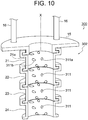
- Figs. 9 to 12 show a configuration of a rotating movable body 300 for a wire rope according to a third embodiment of this invention. Note that identical symbols to the reference symbols in Figs. 1 to 8 denote identical or similar constituent elements, and therefore detailed description thereof has been omitted.
- a rotating portion 302 of the rotating movable body 300 for a wire rope includes the substantially cylindrical case portions 21, 22, 23, 24, which are arranged in the extension direction of the wire rope 1 and capable of rotating relative to each other.
- a plurality of rope-engaging projecting portions 311 are provided on the inner peripheral surfaces of the case portions 21, 22, 23, 24. The rope-engaging projecting portions 311 engage with the grooves between any pair of adjacent strands among the eight strands 1a to 1h of the wire rope 1.
- rope-engaging projecting portions 311 constitute rope engaging portions.
- three rope-engaging projecting portions 311a for engaging with a single groove are provided in a row on the inner peripheral surface of the first case portion 21a serving as one part of the single case portion 21, which is divided into two parts in the direction of the rotary axis X. Further, three rope-engaging projecting portions 311b for engaging with a different single groove are provided in a row on the inner peripheral surface of the first case portion 21a.
- the rope-engaging projecting portions 311a, 311b provided on the inner peripheral surface of the first case portion 21a are provided so as to sandwich one strand 1a among the eight strands 1a to 1h.
- rope-engaging projecting portions 311a, 311b are also provided on the other part of the case portion 21 divided into two parts in the direction of the rotary axis X. Furthermore, similar arrangements of the rope-engaging projecting portions 311 are provided on the inner peripheral surfaces of the case portions 22, 23, 24.
- the rope-engaging projecting portions 311 When attaching the rotating movable body 300 for a wire rope to the wire rope 1, the rope-engaging projecting portions 311 are engaged with all of the grooves provided between the strands 1a to 1h. Further, the case portions 21, 22, 23, 24 are disposed so that the strands 1a to 1h are respectively sandwiched between the rope-engaging projecting portions 311a, 311b arranged in two rows. As a result, the strands 1a to 1h each remain in constant contact with the rope-engaging projecting portions 311 projecting inwardly from the case portions 21, 22, 23, 24.
- the rotating movable body 300 for a wire rope is operated, the pulled portions 16 are pulled upward by a motor (not shown). Accordingly, the case portions 21, 22, 23, 24 move in the extension direction of the wire rope 1 while the pulled portions 16 are pulled, as indicated by an arrow A in Fig. 9 , and the case portions 21, 22, 23, 24 rotate around the wire rope 1 so as to follow the twist of the strands 1a to 1h, as indicated by an arrow B in Fig. 9 . If a deformation has occurred in the wire rope 1, the projecting portions 31 of the case portions 21, 22, 23, 24 catch on the deformed location of the wire rope 1. As a result, a deformation such as a kink in the wire rope 1 can be discovered easily.
- the rope-engaging projecting portions 311 are provided on the inner peripheral surfaces of the case portions 21, 22, 23, 24 as the rope engaging portions.
- the rotating movable body 300 for a wire rope can be manufactured more easily than when a spiral-shaped irregularity is formed on the inner peripheral surface of a single tubular member.
- the amount of processing labor is reduced, and therefore the manufacturing cost of the rotating movable body 300 for a wire rope can be suppressed.
- the rope engaging portion of the rotating movable body 300 for a wire rope is constituted by the plurality of rope-engaging projecting portions 311, and therefore a reduction in the weight of the rotating movable body 300 for a wire rope can be achieved.
- the wire rope 1 can be inspected for deformations easily and at low cost.
- Figs. 13 to 15 show a configuration of a rotating movable body 400 for a wire rope according to a fourth embodiment of this invention. Note that identical symbols to the reference symbols in Figs. 1 to 12 denote identical or similar constituent elements, and therefore detailed description thereof has been omitted.
- a strand contacting portion 411 is provided between the row of rope-engaging projecting portions 311a and the other row of rope-engaging projecting portions 311b on a lower end of the inner peripheral surface of each of the case portions 21, 22, 23, 24, which form a rotating portion 402 of the rotating movable body 400 for a wire rope.
- the strand contacting portion 411 has a cylindrical surface 412.
- the cylindrical surface 412 of the strand contacting portion 411 is shaped in alignment with the outer shape of each of the strands 1a to 1h of the wire rope 1 so as to contact the strands 1a to 1h by surface contact.
- the rotating movable body 400 for a wire rope it is sufficient simply to provide the rope-engaging projecting portions 311 and the strand contacting portions 411 on the inner peripheral surfaces of the case portions 21, 22, 23, 24, and therefore the amount of processing labor can be reduced, enabling a reduction in the manufacturing cost of the rotating movable body 400 for a wire rope.
- the weight of the rotating movable body 400 for a wire rope can also be reduced.
- the strand contacting portions 411 are provided on the inner peripheral surfaces of the case portions 21, 22, 23, 24, and therefore the surface area by which the rotating movable body 400 for a wire rope comes into contact with the strands 1a to 1h of the wire rope 1 increases. As a result, deformations such as kinks can be detected at low cost more reliably.
- the strand contacting portions 411 are not limited to being used together with the rope-engaging projecting portions 311 and may also be provided on the inner peripheral surfaces of the case portions 21, 22, 23, 24 together with the rotary plates 214, 224, 234, 244 of the rotating movable body 200 for a wire rope according to the second embodiment.
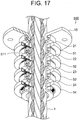
- Figs. 16 to 19 show a configuration of a rotating movable body 500 for a wire rope according to a fifth embodiment of this invention. Note that identical symbols to the reference symbols in Figs. 1 to 15 denote identical or similar constituent elements, and therefore detailed description thereof has been omitted.
- annular portions 51, 52, 53, 54 are provided respectively on the outsides of the case portions 21, 22, 23, 24, which form a rotating portion 502 of the rotating movable body 500 for a wire rope.
- the annular portions 51, 52, 53, 54 respectively include needle sensors 511 that project through the insides of the case portions 21, 22, 23, 24.
- two rope-engaging projecting portions 311 that engage with the groove between two adjacent strands, among the eight strands 1a to 1h, are provided on the inner peripheral surface of the case portion 21.
- a plurality of needle sensors 511 are provided in a vertical direction between the two rope-engaging projecting portions 311. As shown in Fig.
- the plurality of needle sensors 511 of the annular portion 51 are arranged in alignment with the outer shape of the two strands 1a, 1b forming the groove with which the rope-engaging projecting portions 311 engage.
- the tip ends of the needle sensors 551 of the respective annular portions 51, 52, 53, 54 each come into contact with two adjacent strands among the eight strands 1a to 1h of the wire rope 1.
- the needle sensor 551 is capable of detecting variation in the surface shape of the wire rope 1. Therefore, when an irregularity such as a kink exists on the strands 1a to 1h of the wire rope 1, the position of the tip end of the needle sensor 511 shifts during the rotary motion of the rotating movable body 500 for a wire rope, and as a result, the existence of the deformation can be detected easily.
- the rotating movable body 500 for a wire rope similarly to the rotating movable bodies 300, 400 for a wire rope, the amount of processing labor and the weight of the rotating movable body 500 for a wire rope can be reduced. Moreover, by using the rotating movable body 500 for a wire rope, the wire rope 1 can be inspected for deformations easily and at low cost. Furthermore, the needle sensors 551 are disposed on the insides of the case portions 21, 22, 23, 24 so that the tip ends of the needle sensors 511 come into contact with the strands 1a to 1h of the wire rope 1, and as a result, deformations can be detected more precisely.
- the needle sensors 511 are not limited to being used together with the rope-engaging projecting portions 311 and may also be provided on the insides of the case portions 21, 22, 23, 24 together with the rotary plates 214, 224, 234, 244 of the rotating movable body 200 for a wire rope according to the second embodiment.
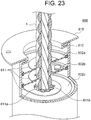
- Figs. 20 to 23 show a configuration of a rotating movable body 600 for a wire rope according to a sixth embodiment of this invention.
- the rotating movable body 600 for a wire rope includes a substantially cylindrical rotating portion holding case 610.
- a substantially annular inward projecting portion 610a that projects inward is formed in an upper end of the rotating portion holding case 610.
- eight substantially annular rotating portion holding rails 603a, 603b, 603c, 603d, 603e, 603f, 603g, 603h are provided at equal intervals in the extension direction of the wire rope 1 on the inner peripheral surface of the rotating portion holding case 610.
- a connecting portion 615 is attached to the upper end of the rotating portion holding case 610.
- the connecting portion 615 is a plate-shaped member having a circular outer shape, and a rope hole 615a is formed in the center thereof. Further, an engaging groove portion 615b that is capable of engaging with the inward projecting portion 610a of the rotating portion holding case 610 is formed on a lower surface side of the connecting portion 615 so as to extend around the rope hole 615a.
- disc plates 602a, 602b, 602c, 602d, 602e, 602f, 602g, 602h having a circular outer shape are respectively held rotatably by the rotating portion holding rails 603a, 603b, 603c, 603d, 603e, 603f, 603g, 603h provided on the inner peripheral surface of the rotating portion holding case 610.
- the disc plates 602a to 602h which are arranged at predetermined intervals in the extension direction of the wire rope 1, together constitute a rotating portion 602 through the interior of which the wire rope 1 passes.
- a rope hole 604 through which the wire rope 1 passes is formed in the center of each of the disc plates 602a to 602h.
- an engaging plate 611 is attached via a fixing member 612 to an upper surface of each of the disc plates 602a to 602h.
- a rope engaging hole 611a is formed in the engaging plate 611.
- the engaging plate 611 is disposed so that the position of the rope engaging hole 611a overlaps the rope hole 604 in the corresponding disc plate 602a to 602h.
- a rope-engaging recessed portion 611b capable of engaging with two of the eight strands 1a to 1h of the wire rope 1 is formed in the rope engaging hole 611a.
- the rope-engaging recessed portion 611b includes two semicircular portions 611c that correspond to the outer shapes of the two strands, and a projecting portion 611d between the two semicircular portions 611c engages with the groove between the strands of the wire rope 1.
- engaging plates 611 constitute rope engaging portions.
- the disc plates 602a to 602h are arranged so that the rope-engaging recessed portions 611b of the respective engaging plates 611 engage with different combinations of two adjacent strands.
- each of the eight strands 1a to 1h comes into contact with the rope-engaging recessed portions 611b formed in two of the eight disc plates 602a to 602h.
- the rotating movable body 600 for a wire rope is operated, the pulled portions 16 are pulled upward by a motor (not shown). Accordingly, the disc plates 602a to 602h move in the extension direction of the wire rope 1 while the pulled portions 16 are pulled, as indicated by an arrow A in Fig. 20 , and the disc plates 602a to 602h rotate around the wire rope 1 so as to follow the twist of the strands 1a to 1h, as indicated by an arrow B in Fig. 20 . If a deformation such as a kink has occurred in the wire rope 1, one of the disc plates 602a to 602h catches on the deformed location of the wire rope 1 such that the rotating movable body 600 for a wire rope becomes unable to move smoothly. As a result, the deformation in the wire rope 1 can be discovered easily.
- the eight disc plates 602a to 602h are arranged at predetermined intervals in the extension direction of the wire rope 1. Accordingly, the engaging plates 611 provided respectively on the disc plates 602a to 602h as the rope engaging portions are also arranged at predetermined intervals in the extension direction of the wire rope 1. Further, the rope-engaging recessed portions 612b formed in the engaging plates 611 each engage with a part of the outer shape of the wire rope 1.
- the rotating movable body 600 for a wire rope which is capable of performing a rotary motion around the wire rope 1, can be manufactured by processing the engaging plates 611 one at a time in alignment with parts of the outer shape of the wire rope 1.
- the rotating portion 602 of the rotating movable body 600 for a wire rope is constituted by the eight disc plates 602a to 602h, while the rope engaging portions are constituted by the eight engaging plates 611, and therefore a reduction in the weight of the rotating movable body 600 for a wire rope can be achieved. Furthermore, by using the rotating movable body 600 for a wire rope, deformations in the wire rope 1 can be detected easily and at low cost.
- the rotating portion 602 of the rotating movable body 600 for a wire rope includes the eight disc plates 602a to 602h corresponding to the eight grooves provided between the strands 1a to 1h of the wire rope 1.
- the engaging plates 611 provided on the disc plates 602a to 602h each include one rope-engaging recessed portion 611b.
- the disc plates 602a to 602h are capable of rotating relative to and independently of each other. As a result, the rotating movable body 600 for a wire rope can be moved around the wire rope 1 without aligning the intervals between the disc plates 602a to 602h with the pitch of the strands 1a to 1h of the wire rope 1.
- the rope-engaging recessed portions 611b are not limited to being formed in the engaging plates 611 and may be formed directly in the disc plates 602a to 602h.
- the disc plates 602a to 602h function as the rotating portion and the rope engaging portions.
- the rotating movable bodies 100, 200, 300, 400, 500, 600 for a wire rope are used as an inspection jig for detecting deformations such as kinks, but the rotating movable bodies 100, 200, 300, 400, 500, 600 for a wire rope are not limited thereto and may also be used to clean the wire rope 1, to remove cornices from a wire rope 1 installed outdoors, and so on.
- the rotating movable bodies 100, 200, 300, 400, 500, 600 for a wire rope are pulled upward by a motor via the pulled portions 16, but are not limited thereto. More specifically, the rotating movable bodies 100, 200, 300, 400, 500, 600 for a wire rope may be pulled up along the wire rope 1 by a mechanism such as a winch or a hydraulic actuator, for example. Furthermore, the rotating movable bodies 100, 200, 300, 400, 500, 600 for a wire rope may be pulled up by a mechanism that ascends and descends along the wire rope 1 while self-rotating or a mechanism that is fixed to the top of the wire rope 1. Further, the rotating movable bodies 100, 200, 300, 400, 500, 600 for a wire rope may move in a descending direction as well as the ascending direction indicated by the arrow A.
- a small camera may be disposed on an upper portion or a lower portion of the rotating movable bodies 100, 200, 300, 400, 500, 600 for a wire rope so that the location of the deformation can be visually confirmed.
- the small camera may be provided with an LED, and a power supply of the LED may be configured to be capable of using power generated by the rotation of the rotating movable bodies 100, 200, 300, 400, 500, 600 for a wire rope.
Landscapes
- Engineering & Computer Science (AREA)
- General Engineering & Computer Science (AREA)
- Physics & Mathematics (AREA)
- General Physics & Mathematics (AREA)
- Mechanical Engineering (AREA)
- Ropes Or Cables (AREA)
- Lift-Guide Devices, And Elevator Ropes And Cables (AREA)
- Maintenance And Inspection Apparatuses For Elevators (AREA)
Applications Claiming Priority (2)
| Application Number | Priority Date | Filing Date | Title |
|---|---|---|---|
| JP2018193186A JP6561364B1 (ja) | 2018-10-12 | 2018-10-12 | ワイヤロープ用回転移動体 |
| PCT/JP2019/019121 WO2020075332A1 (ja) | 2018-10-12 | 2019-05-14 | ワイヤロープ用回転移動体 |
Publications (2)
| Publication Number | Publication Date |
|---|---|
| EP3789337A1 true EP3789337A1 (de) | 2021-03-10 |
| EP3789337A4 EP3789337A4 (de) | 2022-01-26 |
Family
ID=67689579
Family Applications (1)
| Application Number | Title | Priority Date | Filing Date |
|---|---|---|---|
| EP19870338.1A Pending EP3789337A4 (de) | 2018-10-12 | 2019-05-14 | Rotierender beweglicher körper für drahtseil |
Country Status (5)
| Country | Link |
|---|---|
| US (1) | US11898693B2 (de) |
| EP (1) | EP3789337A4 (de) |
| JP (1) | JP6561364B1 (de) |
| CN (1) | CN112272648B (de) |
| WO (1) | WO2020075332A1 (de) |
Families Citing this family (4)
| Publication number | Priority date | Publication date | Assignee | Title |
|---|---|---|---|---|
| WO2022003817A1 (ja) * | 2020-06-30 | 2022-01-06 | 理研興業株式会社 | ワイヤロープ用回転移動体 |
| JP7497693B2 (ja) * | 2021-02-17 | 2024-06-11 | 株式会社島津製作所 | ワイヤロープ検査装置 |
| CN113428758B (zh) * | 2021-07-12 | 2022-10-28 | 宸宇电梯科技有限公司 | 一种电梯曳引绳检修工具 |
| CN114194972B (zh) * | 2021-12-12 | 2023-05-02 | 南通兴华达高实业有限公司 | 一种具有二次保护的电梯平衡补偿链及其安装方法 |
Family Cites Families (31)
| Publication number | Priority date | Publication date | Assignee | Title |
|---|---|---|---|---|
| NL3834C (nl) * | 1916-09-28 | 1919-10-01 | Verbetering aan een toestel voor het reinigen van kabels. | |
| US2594143A (en) * | 1947-08-23 | 1952-04-22 | Fichter Julius | Adjustable ring and thread gauge |
| US3477136A (en) * | 1967-11-28 | 1969-11-11 | Lowell C Johnson | Dimensional gage with equalized spring pressure |
| FR2045155A5 (de) * | 1969-06-10 | 1971-02-26 | Tractel Sa | |
| US4338565A (en) * | 1980-07-11 | 1982-07-06 | Exploration Logging, Inc. | Method and apparatus for measuring the movement of a spiral wound wire rope |
| JPS606478Y2 (ja) * | 1981-07-30 | 1985-03-01 | 三菱重工業株式会社 | ワイヤロ−プ類の点検治具 |
| JPS6198235A (ja) * | 1984-10-18 | 1986-05-16 | コーリン電子株式会社 | 血圧測定装置 |
| JP3339929B2 (ja) * | 1992-08-05 | 2002-10-28 | 本州四国連絡橋公団 | ワイヤロープ外面処理工具 |
| JPH0673071U (ja) * | 1993-03-26 | 1994-10-11 | 住友建機株式会社 | ワイヤーロープの点検装置 |
| US5490333A (en) * | 1994-02-01 | 1996-02-13 | Nelson; Russell | Three point tri-roll threaded ring gauge that is adjustable with wear detectors |
| JPH0912247A (ja) * | 1995-06-28 | 1997-01-14 | Mitsubishi Denki Bill Techno Service Kk | エレベータ主ワイヤロープ給油治具 |
| RU2135404C1 (ru) * | 1998-02-18 | 1999-08-27 | Новочеркасский государственный технический университет | Дефектоскоп для подъемных канатов |
| GB0522593D0 (en) * | 2005-11-07 | 2005-12-14 | Univ Leicester | Bacterial growth enhancer |
| WO2007086865A1 (en) * | 2006-01-27 | 2007-08-02 | Huemann Steven A | Cylindrical member maintenance device |
| US20090044369A1 (en) * | 2007-08-16 | 2009-02-19 | Heumann Steven A | Cylindrical member maintenance device including cutting ring |
| JP2009263101A (ja) * | 2008-04-25 | 2009-11-12 | Toshiba Elevator Co Ltd | エレベータのロープ素線状態検出装置 |
| JP5374428B2 (ja) | 2010-03-24 | 2013-12-25 | 三菱電機株式会社 | ロープ清掃装置 |
| CN201883335U (zh) * | 2010-08-18 | 2011-06-29 | 洛阳百克特摩擦材料有限公司 | 一种钢丝绳除油器 |
| JP2013095534A (ja) * | 2011-10-28 | 2013-05-20 | Hitachi Building Systems Co Ltd | ワイヤロープの探傷装置 |
| JP5591273B2 (ja) * | 2012-03-29 | 2014-09-17 | 三菱電機株式会社 | ワイヤロープ清掃治具 |
| JP5427918B2 (ja) | 2012-05-30 | 2014-02-26 | 東芝エレベータ株式会社 | エレベータのロープ清掃冶具 |
| US9649667B2 (en) * | 2013-08-15 | 2017-05-16 | Muehlhan Ag | Apparatus for surface treatment of an elongate object |
| CN106458510A (zh) * | 2014-02-18 | 2017-02-22 | 奥的斯电梯公司 | 用于电梯受拉构件的检查系统的连接器 |
| KR101630773B1 (ko) * | 2014-10-06 | 2016-06-15 | 주식회사 포스코 | 로프 점검장치 및 로프 점검방법 |
| JP2017039559A (ja) * | 2015-08-18 | 2017-02-23 | 三菱電機ビルテクノサービス株式会社 | エレベータ用ロープテスタ装置 |
| JP2018034916A (ja) * | 2016-08-29 | 2018-03-08 | 株式会社日立ビルシステム | ワイヤロープ用素線点検治具及びワイヤロープ用素線点検方法 |
| JP6571055B2 (ja) * | 2016-09-07 | 2019-09-04 | 株式会社日立ビルシステム | ワイヤーロープ清掃装置 |
| JP6817794B2 (ja) * | 2016-11-16 | 2021-01-20 | 三菱電機ビルテクノサービス株式会社 | エレベーターロープ引掛り点検装置およびエレベーターロープ引掛り点検方法 |
| JP6472468B2 (ja) * | 2017-02-06 | 2019-02-20 | 理研興業株式会社 | 回転移動体を用いたロープ部材連結具、発電装置、視線誘導装置、雪庇を除去する装置、及びロープ部材を製造する方法 |
| JP6815275B2 (ja) * | 2017-05-23 | 2021-01-20 | 三菱電機ビルテクノサービス株式会社 | エレベーターロープ素線破断検出装置 |
| JP6462819B1 (ja) * | 2017-10-03 | 2019-01-30 | 東芝エレベータ株式会社 | 締付器具及びロープ清掃方法 |
-
2018
- 2018-10-12 JP JP2018193186A patent/JP6561364B1/ja active Active
-
2019
- 2019-05-14 CN CN201980037685.8A patent/CN112272648B/zh active Active
- 2019-05-14 WO PCT/JP2019/019121 patent/WO2020075332A1/ja not_active Ceased
- 2019-05-14 EP EP19870338.1A patent/EP3789337A4/de active Pending
- 2019-05-14 US US15/734,479 patent/US11898693B2/en active Active
Also Published As
| Publication number | Publication date |
|---|---|
| JP6561364B1 (ja) | 2019-08-21 |
| JP2020059592A (ja) | 2020-04-16 |
| WO2020075332A1 (ja) | 2020-04-16 |
| US20210270415A1 (en) | 2021-09-02 |
| EP3789337A4 (de) | 2022-01-26 |
| CN112272648A (zh) | 2021-01-26 |
| CN112272648B (zh) | 2022-04-19 |
| US11898693B2 (en) | 2024-02-13 |
Similar Documents
| Publication | Publication Date | Title |
|---|---|---|
| US11898693B2 (en) | Rotating movable body for wire rope | |
| EP2576121B1 (de) | Schweissdrahtführungsmantel mit mehreren über einen frei rotierbaren ring und ein drehgelenk untereinander verbundenen führungskörpern | |
| US11639759B2 (en) | Wiring member support device | |
| KR20190095867A (ko) | 프로브 핀, 검사 지그, 검사 유닛 및 검사 장치 | |
| JP2013076452A (ja) | ケーブル支持装置 | |
| KR20100099620A (ko) | 증착용 마스크 | |
| CN102577032A (zh) | 设有焊接的磁体保持元件的永磁体转子组件 | |
| JP5032714B1 (ja) | ケーブル支持部材 | |
| JP2014206443A (ja) | 試験管ラック | |
| TW201514566A (zh) | 光纖感測器用光纖單元 | |
| KR102239477B1 (ko) | 리프트 핀 지지 어셈블리 | |
| CN105612362A (zh) | 滚子轴承保持器、其组装及生产方法和滚子轴承 | |
| KR20230086741A (ko) | 롤러 장치 | |
| JP6557997B2 (ja) | 直動案内装置 | |
| JP2021049974A (ja) | ケーブルによる車両輸送設備の牽引ケーブルを支持して案内するための装置及び方法 | |
| JP6002520B2 (ja) | 巻線機用ガイドローラ | |
| KR20220079990A (ko) | 카메라 모듈의 제조 방법, 카메라 모듈 | |
| KR20100099840A (ko) | 혼용 케이블 베어 | |
| US20170050804A1 (en) | Pot conveying system | |
| KR20120114704A (ko) | 처짐 보상이 용이한 핸들링 로봇 | |
| KR101685907B1 (ko) | 스트랜드 가이딩 소자 | |
| JP2013096469A (ja) | 伝動ベルト | |
| KR20120121979A (ko) | 롤러 앗세이 | |
| JP2018157713A (ja) | ケーブル支持部材及びケーブル支持装置 | |
| KR102818228B1 (ko) | 정렬 가이드부가 구비된 금속파이프 권취장치 |
Legal Events
| Date | Code | Title | Description |
|---|---|---|---|
| STAA | Information on the status of an ep patent application or granted ep patent |
Free format text: STATUS: THE INTERNATIONAL PUBLICATION HAS BEEN MADE |
|
| PUAI | Public reference made under article 153(3) epc to a published international application that has entered the european phase |
Free format text: ORIGINAL CODE: 0009012 |
|
| STAA | Information on the status of an ep patent application or granted ep patent |
Free format text: STATUS: REQUEST FOR EXAMINATION WAS MADE |
|
| 17P | Request for examination filed |
Effective date: 20201201 |
|
| AK | Designated contracting states |
Kind code of ref document: A1 Designated state(s): AL AT BE BG CH CY CZ DE DK EE ES FI FR GB GR HR HU IE IS IT LI LT LU LV MC MK MT NL NO PL PT RO RS SE SI SK SM TR |
|
| AX | Request for extension of the european patent |
Extension state: BA ME |
|
| REG | Reference to a national code |
Ref country code: DE Ref legal event code: R079 Free format text: PREVIOUS MAIN CLASS: B66B0007120000 Ipc: D07B0007160000 |
|
| DAV | Request for validation of the european patent (deleted) | ||
| DAX | Request for extension of the european patent (deleted) | ||
| A4 | Supplementary search report drawn up and despatched |
Effective date: 20211223 |
|
| RIC1 | Information provided on ipc code assigned before grant |
Ipc: D07B 1/14 20060101ALN20211217BHEP Ipc: B66B 7/12 20060101ALN20211217BHEP Ipc: D07B 7/16 20060101AFI20211217BHEP |
|
| STAA | Information on the status of an ep patent application or granted ep patent |
Free format text: STATUS: EXAMINATION IS IN PROGRESS |
|
| 17Q | First examination report despatched |
Effective date: 20240412 |