EP3779986A1 - Aufzeichnungsverfahren, aufzeichnungsvorrichtung, wiedergabeverfahren, wiedergabevorrichtung und hochgeschwindigkeitsreaktionselement - Google Patents
Aufzeichnungsverfahren, aufzeichnungsvorrichtung, wiedergabeverfahren, wiedergabevorrichtung und hochgeschwindigkeitsreaktionselement Download PDFInfo
- Publication number
- EP3779986A1 EP3779986A1 EP18911675.9A EP18911675A EP3779986A1 EP 3779986 A1 EP3779986 A1 EP 3779986A1 EP 18911675 A EP18911675 A EP 18911675A EP 3779986 A1 EP3779986 A1 EP 3779986A1
- Authority
- EP
- European Patent Office
- Prior art keywords
- magnetization
- light
- magnetic field
- recording medium
- magnetic recording
- Prior art date
- Legal status (The legal status is an assumption and is not a legal conclusion. Google has not performed a legal analysis and makes no representation as to the accuracy of the status listed.)
- Pending
Links
Images








Classifications
-
- G—PHYSICS
- G11—INFORMATION STORAGE
- G11B—INFORMATION STORAGE BASED ON RELATIVE MOVEMENT BETWEEN RECORD CARRIER AND TRANSDUCER
- G11B5/00—Recording by magnetisation or demagnetisation of a record carrier; Reproducing by magnetic means; Record carriers therefor
- G11B5/02—Recording, reproducing, or erasing methods; Read, write or erase circuits therefor
-
- G—PHYSICS
- G11—INFORMATION STORAGE
- G11B—INFORMATION STORAGE BASED ON RELATIVE MOVEMENT BETWEEN RECORD CARRIER AND TRANSDUCER
- G11B5/00—Recording by magnetisation or demagnetisation of a record carrier; Reproducing by magnetic means; Record carriers therefor
- G11B5/62—Record carriers characterised by the selection of the material
- G11B5/68—Record carriers characterised by the selection of the material comprising one or more layers of magnetisable material homogeneously mixed with a bonding agent
- G11B5/70—Record carriers characterised by the selection of the material comprising one or more layers of magnetisable material homogeneously mixed with a bonding agent on a base layer
- G11B5/706—Record carriers characterised by the selection of the material comprising one or more layers of magnetisable material homogeneously mixed with a bonding agent on a base layer characterised by the composition of the magnetic material
- G11B5/70626—Record carriers characterised by the selection of the material comprising one or more layers of magnetisable material homogeneously mixed with a bonding agent on a base layer characterised by the composition of the magnetic material containing non-metallic substances
- G11B5/70642—Record carriers characterised by the selection of the material comprising one or more layers of magnetisable material homogeneously mixed with a bonding agent on a base layer characterised by the composition of the magnetic material containing non-metallic substances iron oxides
-
- G—PHYSICS
- G11—INFORMATION STORAGE
- G11B—INFORMATION STORAGE BASED ON RELATIVE MOVEMENT BETWEEN RECORD CARRIER AND TRANSDUCER
- G11B5/00—Recording by magnetisation or demagnetisation of a record carrier; Reproducing by magnetic means; Record carriers therefor
- G11B5/012—Recording on, or reproducing or erasing from, magnetic disks
-
- G—PHYSICS
- G11—INFORMATION STORAGE
- G11B—INFORMATION STORAGE BASED ON RELATIVE MOVEMENT BETWEEN RECORD CARRIER AND TRANSDUCER
- G11B5/00—Recording by magnetisation or demagnetisation of a record carrier; Reproducing by magnetic means; Record carriers therefor
- G11B5/62—Record carriers characterised by the selection of the material
- G11B5/68—Record carriers characterised by the selection of the material comprising one or more layers of magnetisable material homogeneously mixed with a bonding agent
- G11B5/70—Record carriers characterised by the selection of the material comprising one or more layers of magnetisable material homogeneously mixed with a bonding agent on a base layer
- G11B5/706—Record carriers characterised by the selection of the material comprising one or more layers of magnetisable material homogeneously mixed with a bonding agent on a base layer characterised by the composition of the magnetic material
-
- H—ELECTRICITY
- H01—ELECTRIC ELEMENTS
- H01F—MAGNETS; INDUCTANCES; TRANSFORMERS; SELECTION OF MATERIALS FOR THEIR MAGNETIC PROPERTIES
- H01F1/00—Magnets or magnetic bodies characterised by the magnetic materials therefor; Selection of materials for their magnetic properties
- H01F1/01—Magnets or magnetic bodies characterised by the magnetic materials therefor; Selection of materials for their magnetic properties of inorganic materials
- H01F1/03—Magnets or magnetic bodies characterised by the magnetic materials therefor; Selection of materials for their magnetic properties of inorganic materials characterised by their coercivity
- H01F1/032—Magnets or magnetic bodies characterised by the magnetic materials therefor; Selection of materials for their magnetic properties of inorganic materials characterised by their coercivity of hard-magnetic materials
- H01F1/10—Magnets or magnetic bodies characterised by the magnetic materials therefor; Selection of materials for their magnetic properties of inorganic materials characterised by their coercivity of hard-magnetic materials non-metallic substances, e.g. ferrites, e.g. [(Ba,Sr)O(Fe2O3)6] ferrites with hexagonal structure
- H01F1/11—Magnets or magnetic bodies characterised by the magnetic materials therefor; Selection of materials for their magnetic properties of inorganic materials characterised by their coercivity of hard-magnetic materials non-metallic substances, e.g. ferrites, e.g. [(Ba,Sr)O(Fe2O3)6] ferrites with hexagonal structure in the form of particles
- H01F1/113—Magnets or magnetic bodies characterised by the magnetic materials therefor; Selection of materials for their magnetic properties of inorganic materials characterised by their coercivity of hard-magnetic materials non-metallic substances, e.g. ferrites, e.g. [(Ba,Sr)O(Fe2O3)6] ferrites with hexagonal structure in the form of particles in a bonding agent
Definitions
- the present invention relates to a recording method, a recording device, a reproduction method, a reproduction device, and a high-speed response element, and is preferably applied to a magnetic recording medium or the like using epsilon iron oxide particles.
- a magnetic recording medium In a magnetic recording medium, there has been a demand for the miniaturization of magnetic particles in order for the densification of recording, and recently, a magnetic recording medium using epsilon iron oxide particles in which the magnetic particles can be miniaturized has attracted attention.
- an S/N ratio of a signal can be increased, whereas it is considered that the stability of the magnetization with respect to heat is proportional to a magnetic anisotropic constant and a particle volume, and thus, thermal stability of the magnetization is impaired by the miniaturization.
- the magnetic anisotropic constant can be increased by increasing a coercive force of the magnetic recording medium. Accordingly, in order to obtain particles having a small particle volume (particle diameter) and high thermal stability, it is effective to use a substance having a high coercive force as a magnetic material.
- a substance having a high coercive force as a magnetic material.
- the inventors have disclosed epsilon iron oxide particles in which a coercive force H c of greater than 20 kOe (1.59 ⁇ 10 6 A/m) is observed in a magnetic hysteresis loop that is measured by applying an external magnetic field in a parallel direction to an orientation direction of a magnetization easy axis.
- the external magnetic field that is generated by the magnetic head in general, is also regarded as being proportional to a saturated magnetic flux density of a soft magnetic film to be used, and currently, a hard disk having a coercive force H c of approximately 1.5 to 4.5 kOe (1.19 ⁇ 10 5 A/m to 3.58 ⁇ 10 5 A/m) has been reported, but in a record writing magnetic head of such a hard disk, a material having a high saturated magnetic flux density such as a saturated magnetic flux density of 2.4 T has been used.
- the invention has been made in consideration of the above, and an object thereof is to propose a recording method and a recording device in which information can be easily recorded even in a magnetic recording medium using epsilon iron oxide particles having a high coercive force as a magnetic recording material.
- Another object of the invention is to propose a reproduction method and a reproduction device in which information can be reproduced even in a case where the information is recorded in a magnetic recording medium using epsilon iron oxide particles as a magnetic recording material in a multi-valued manner.
- the invention has also been made in consideration of the above, and an object thereof is to propose a novel high-speed response element using epsilon iron oxide particles.
- a recording method includes: performing application of an external magnetic field and irradiation of light to a magnetic recording medium using epsilon iron oxide particles as a magnetic recording material to invert magnetization of the epsilon iron oxide particles.
- a recording device of the invention includes: a magnetic field application unit that is configured to apply an external magnetic field to a magnetic recording medium containing epsilon iron oxide particles; and a light irradiation unit that is configured to irradiate the magnetic recording medium with light, in which magnetization of the epsilon iron oxide particles is inverted by the external magnetic field and the light.
- a reproduction method of the invention includes: detecting magnetization of a magnetic recording medium using epsilon iron oxide particles as a magnetic recording material, in which information is capable of being recorded in a multi-valued manner; and reproducing information in accordance with intensity of the magnetization, on the basis of the intensity of the magnetization detected from the magnetic recording medium.
- a reproduction device of the invention includes: a detection unit that is configured to detect magnetization of a magnetic recording medium using epsilon iron oxide particles as a magnetic recording material, in which information is capable of being recorded in a multi-valued manner; and an information reproduction unit that is configured to reproduce information in accordance with intensity of the magnetization, on the basis of the intensity of the magnetization detected from the magnetic recording medium.
- a high-speed response element of the invention contains: epsilon iron oxide particles, in which a magnetization state responds in conformance with a timing when terahertz light is applied.
- a magnetic recording medium using epsilon iron oxide particles is irradiated with light, and thus, it is possible to decrease an external magnetic field that is required to invert magnetization, compared to a case where the magnetic recording medium is not irradiated with light. Accordingly, even in a magnetic recording medium using epsilon iron oxide particles having a high coercive force, it is possible to easily record information in a low external magnetic field by irradiating the magnetic recording medium with light.
- the reproduction method and the reproduction device of the invention even in a case where information is recorded in a magnetic recording medium in a multi-valued manner by changing the intensity of light at the time of recording the information by an external magnetic field and light, it is possible to reproduce multi-valued information by detecting the intensity of the magnetization.
- a magnetic recording medium of a recording device of the invention it is desirable to apply a magnetic recording medium using epsilon iron oxide particles having a high coercive force H c as a magnetic recording material.
- the epsilon iron oxide particles having a high coercive force H c are used as the magnetic recording material, the epsilon iron oxide particles are irradiated with light, and thus, it is possible to invert magnetization in a low external magnetic field and to record information, without using a magnetic head having a saturated magnetic flux density at a high level.
- the epsilon iron oxide particles having a high coercive force H c which are used in this embodiment, will be described below.
- the epsilon iron oxide particles any crystals represented by general formulas of ⁇ -Fe 2 O 3 , ⁇ -A x Fe 2-x O 3 (A is an element excluding Fe, and x is in a range of 0 ⁇ x ⁇ 2), ⁇ -B y C z Fe 2-y-z O 3 (here, B and C are elements excluding A and Fe and are elements different from each other, y is in a range of 0 ⁇ y ⁇ 1, and z is in a range of 0 ⁇ z ⁇ 1), and ⁇ -D U E V F W Fe 2-U-V-W O 3 (here, D, E, and F are elements excluding A and Fe and are elements different from each other, U is in a range of 0 ⁇ U ⁇ 1, V is in a range of 0 ⁇ V
- ⁇ -A x Fe 2-x O 3 has the same crystalline system and the same space group as those of ⁇ -Fe 2 O 3 , in which a part of a Fe site of the ⁇ -Fe 2 O 3 crystals is substituted with the element A other than Fe.
- a trivalent element as A.
- examples of A are capable of including one type of element selected from Al, Sc, Ti, V, Cr, Ga, In, Y, and Rh.
- ⁇ -B y C z Fe 2-y-z O 3 has the same crystalline system and the same space group as those of ⁇ -Fe 2 O 3 , in which a part of a Fe site of the ⁇ -Fe 2 O 3 crystals is substituted with two types of elements B and C other than Fe.
- B tetravalent element
- C divalent element
- ⁇ -D U E V F W Fe 2-U-V-W O 3 has the same crystalline system and the same space group as those of ⁇ -Fe 2 O 3 , in which a part of a Fe site of the ⁇ -Fe 2 O 3 crystals is substituted with three types of elements D, E, and F other than Fe.
- D is preferable to use a trivalent element as D, to use a tetravalent element as E, and to use a divalent element as F.
- D are capable of including one type of element selected from Al, Sc, Ti, V, Cr, Ga, In, Y, and Rh.
- examples of E are capable of including Ti
- examples of F are capable of including one type of element selected from Co, Ni, Mn, Cu, and Zn.
- a particle diameter of the epsilon iron oxide particles is not particularly limited, and for example, it is desirable that an average particle diameter measured from a transmission-type electron microscope (TEM) picture is in a range of 5 nm to 200 nm, and in order to increase a recording density of the magnetic recording medium, the average particle diameter is more desirably 100 nm or less, is even more desirably 50 nm or less, and is still even more desirably 20 nm or less.
- TEM transmission-type electron microscope
- Such epsilon iron oxide particles are known.
- the epsilon iron oxide particles containing any of the ⁇ -A x Fe 2-x O 3 crystals, the ⁇ -B y C z Fe 2-y-z O 3 crystals, and the ⁇ -D U E V F W Fe 2-U-V-W O 3 crystals in which a part of the Fe site is substituted with each of one type of element A, two types of elements B and C, and three types of elements D, E, and F, other than Fe, for example, can be synthesized by a step in which a reverse-micelle method and a sol-gel method are combined, and a burning step.
- the epsilon iron oxide particles can be synthesized by a step in which a direct synthesis method and a sol-gel method are combined, and a burning step.
- a particle dispersion element used in the recording device of this embodiment is manufactured as follows.
- a dispersion liquid obtained by dispersing the epsilon iron oxide particles described above in a predetermined solvent is provided on a base.
- a polyester film is pasted onto a glass substrate, and the dispersion liquid is dropped onto the film.
- the dispersion liquid provided on the base is placed at a magnetic flux density of 2 teslas or more from the viewpoint of increasing orientation reliability, and the dispersion liquid is cured, and thus, a film-like particle dispersion element can be obtained.
- a detailed manufacturing method of such a film-like particle dispersion element is disclosed in JP-A-2016-135737 , and thus, here, the description thereof will be omitted.
- the coercive force H c at a room temperature is 3 kOe (2.39 ⁇ 10 5 A/m) or more.
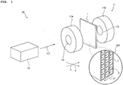
- Fig. 1 illustrates a recording device 10 according to the invention.
- the recording device 10 includes a magnetic field application unit 11 and a light irradiation unit 12, and is capable of recording information by changing a magnetization direction of a particle dispersion element 1 with the magnetic field application unit 11 and the light irradiation unit 12.
- the magnetic field application unit 11 includes a first coil portion 11a and a second coil portion 11b, and for example, forms an external magnetic field H 0 toward the second coil portion 11b from the first coil portion 11a by allowing a current to flow to the first coil portion 11a and the second coil portion 11b.
- the first coil portion 11a and the second coil portion 11b include a through hole 13 that penetrates the thickness of a facing surface facing a recording surface, and the through hole 13 of the first coil portion 11a and the through hole 13 of the second coil portion 11b are disposed to face each other.
- the recording surface of the particle dispersion element 1 is disposed between the first coil portion 11a and the second coil portion 11b such that a surface direction of the recording surface is positioned to be perpendicular to an external magnetic field direction x of the external magnetic field H 0 . Accordingly, the external magnetic field H 0 is applied to the particle dispersion element 1 to be perpendicular to the recording surface.
- the particle dispersion element 1 is disposed between the facing through holes 13 of the first coil portion 11a and the second coil portion 11b.
- the light irradiation unit 12 applies light L1 at a wavelength that can be absorbed by the epsilon iron oxide particles used as the magnetic recording material.
- the light L1 exiting from the light irradiation unit 12 may be pulsed laser light in addition to continuous laser light, and may be an ultraviolet ray (280 nm or more and less than 400 nm) or a visible light ray (400 nm or more and 780 nm or less).
- the light irradiation unit 12 applies the light L1 toward the through hole 13 of the first coil portion 11a and the second coil portion 11b, and irradiates the recording surface of the particle dispersion element 1 with the light L1 through the through hole 13 of the first coil portion 11a.
- the light L1 applied to the recording surface of the particle dispersion element 1 through the through hole 13 of the first coil portion 11a is transmitted through the recording surface, and exits to the outside from the through hole 13 of the second coil portion 11b.
- the light L1 applied to the recording surface of the particle dispersion element 1 directly passes through the through hole 13 of the second coil portion 11b to the outside, and thus, scattered reflection of the light L1 between the first coil portion 11a and the second coil portion 11b can be suppressed, and portions other than an irradiation portion can be prevented from being affected by the light L1.
- the light irradiation unit 12 is capable of irradiating only a desired portion on the recording surface of the particle dispersion element 1 with the light L1.
- the recording device 10 while applying the external magnetic field H 0 by the magnetic field application unit 11, it is possible to irradiate a predetermined region of the particle dispersion element 1 to which the external magnetic field H 0 is applied with the light L1.
- a quadrilateral particle dispersion element 1 is illustrated, and for example, a strip-like particle dispersion element 1 may be used.
- a longitudinal direction of the particle dispersion element 1 is conveyed in a predetermined direction y orthogonal to the external magnetic field direction x, and thus, it is possible to continuously record information in the particle dispersion element 1.
- An area ER in Fig. 1 is a schematic view that illustrates a sectional configuration in which a partial region of the particle dispersion element 1 is extracted and schematically illustrates the magnetization 3 in section.
- the magnetization direction is oriented in a reverse direction (hereinafter, referred to as an initial orientation direction) x1 of the external magnetic field direction x.
- the magnetization 3 in a region ER1 to which the external magnetic field H 0 is applied is affected by the external magnetic field H 0 , and is inclined with respect to a thickness direction of the particle dispersion element 1 by a predetermined angle.
- the epsilon iron oxide particles used as the magnetic recording material have a high coercive force H c , and thus, it is difficult to invert the magnetization 3 by 180 degrees only with the external magnetic field H 0 that is applied by the magnetic field application unit 11, and the magnetization 3 is merely inclined, and thus, it is not possible to record information.
- the particle dispersion element 1 is irradiated with the light L1 from the light irradiation unit 12 in a state where the external magnetic field H 0 is applied in the external magnetic field direction x.
- the magnetization 3 that is inclined by the external magnetic field H 0 is excited by the light L1.
- the direction of the magnetization 3 is inclined by the application of the external magnetic field H 0 , and the magnetization 3 is excited by the irradiation of the light L1, and thus, the light L1 assists magnetization inversion, and as illustrated in Fig. 4 , the magnetization direction is inverted from the initial orientation direction x1 by 180 degrees.
- the magnetization 3 in a region ER3 to which the external magnetic field H 0 is applied and the light L1 is applied is in a state in which the magnetization direction is directed to an inversion direction x2 that is inverted from the initial orientation direction x1 by 180 degrees, and information is recorded.
- a phenomenon that magnetization 3 is inverted by the application of the external magnetic field H 0 and the irradiation of the light L1 (hereinafter, also referred to as a magnetization inversion process) will be described below by using Fig. 5 and Fig. 6 , from the viewpoint of potential energy.
- Fig. 5 illustrates an energy potential when the external magnetic field H 0 is not applied and the light L1 is not applied.
- the magnetization direction in a magnetization stable position directed in the initial orientation direction x1 is set to 0 degrees
- the magnetization direction in a magnetization stable position subjected to the magnetization inversion is set to 180 degrees, on a horizontal axis of Fig. 5 .
- an energy minimum portion appears in the vicinity of 0 degrees and in the vicinity of 180 degrees
- an energy barrier of the magnetization inversion appears between 0 degrees and 180 degrees.
- the magnetization in the vicinity of 0 degrees is not capable of being inverted by the energy barrier.
- the energy potential is changed, and the energy potential in the vicinity of 0 degrees increases, the energy potential in the vicinity of 180 degrees decreases, and the energy minimum portion appears in the vicinity of 180 degrees.
- the energy barrier of the magnetization inversion still exists between 0 degrees and 180 degrees, and the magnetization direction of 0 degrees is maintained.
- the case of irradiating the particle dispersion element 1 with the light L1 while applying the external magnetic field H 0 to the particle dispersion element 1 is described, but the invention is not limited thereto.
- the light L1 is applied while the magnetization 3 in the particle dispersion element 1 is inclined, immediately after the application of the external magnetic field H 0 to the particle dispersion element 1 is ended, and thus, it is possible to assist the inversion of the magnetization 3 with the light L1.
- the particle dispersion element 1 may be initially irradiated with the light L1
- the external magnetic field H 0 may be applied to the particle dispersion element 1 that is irradiated with the light L1
- the inversion of the magnetization 3 may be assisted with the external magnetic field H 0 .
- the external magnetic field H 0 is applied while the magnetization 3 is excited with light in the particle dispersion element 1, immediately after the particle dispersion element 1 is irradiated with the light L1, and thus, it is also possible to assist the inversion of the magnetization 3 with the external magnetic field H 0 .
- the recording device 10 when information is recorded in the particle dispersion element 1 using the epsilon iron oxide particles as the magnetic recording material, the external magnetic field H 0 that inclines the magnetization 3 of the epsilon iron oxide particles is applied to the particle dispersion element 1, and the particle dispersion element 1 is irradiated with the light L1. Accordingly, the recording device 10 is capable of inverting the magnetization 3 that is not capable of being inverted only with the external magnetic field, by a synergetic effect between the inclination of the magnetization 3 and the light excitation of the magnetization 3.
- the particle dispersion element 1 using the epsilon iron oxide particles is irradiated with the light L1, and thus, it is possible to decrease the value of the external magnetic field H 0 that is required to invert the magnetization 3, compared to a case where the particle dispersion element 1 is not irradiated with the light L1. Accordingly, even in the particle dispersion element 1 using the epsilon iron oxide particles having a high coercive force H c , it is possible to easily record information by a low external magnetic field H 0 .
- a film-like particle dispersion element using epsilon iron oxide particles having a high coercive force H c as a magnetic recording material was prepared and was irradiated with light, and thus, a validation test of whether it is possible to decrease an external magnetic field H 0 that is required in magnetization inversion was performed.
- epsilon iron oxide particles containing ⁇ -Ga 0.27 Ti 0.05 Co 0.07 Fe 1.61 O 3 crystals were prepared by the following procedure.
- the epsilon iron oxide particles containing the ⁇ -Ga 0.27 Ti 0.05 Co 0.07 Fe 1.61 O 3 crystals synthesized by a known method were dispersed in a dispersion liquid containing tetramethyl ammonium hydroxide (TMAH), and were classified by a centrifugal separation treatment, and thus, a powder sample having a homogeneous particle diameter was obtained.
- the powder sample was observed with a transmission-type electron microscope (TEM), and thus, it was possible to check that the powder sample was spherical particles.
- TEM transmission-type electron microscope
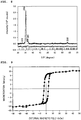
- the particle diameter of the powder sample was examined, and thus, results as shown in Fig. 7 were obtained. As shown in Fig. 7 , it was possible to check that an average particle diameter of the powder sample was 19.2 ⁇ 4.2 nm and the powder sample had an excellent and homogeneous particle diameter distribution.
- the particle dispersion element 1 used in the validation test was prepared by using the classified powder sample.
- a mixture in which a urethane resin and a vinyl chloride resin were mixed was prepared as a resin for a particle dispersion element, and a dispersion liquid in which the mixture and the classified powder sample were dispersed in a predetermined solvent was prepared.
- the dispersion liquid was dropped onto a polyester film (also simply referred to as a film), was placed at a magnetic flux density of 2 T, and was dried, and thus, a transparent particle dispersion element 1 in which the dispersion liquid was cured was obtained. Note that, at this time, the film was disposed such that a magnetic flux density was applied in a perpendicular direction.
- an external magnetic field ( H 0 ) was applied to a recording surface of the particle dispersion element 1 at 300 K in the perpendicular direction, and magnetic hysteresis of the particle dispersion element 1 was measured, and thus, results as shown in Fig. 9 were obtained.
- a coercive force H c of the particle dispersion element 1 was 3.3 kOe (2.63 ⁇ 10 5 A/m), and a square hysteresis ratio had a high value of 0.737.
- an absorption spectrum of an ultraviolet ray and a visible light ray of the particle dispersion element 1 was measured by using an ultraviolet-visible near infrared spectrophotometer JASCO V-670, manufactured by JASCO Corporation, and thus, results as shown in Fig. 10 were obtained. From Fig. 10 , it was possible to check that the particle dispersion element 1 absorbed light from an ultraviolet ray to a visible light ray having a wavelength of approximately 600 nm.
- the obtained particle dispersion element 1 was subjected to a laser light irradiation test using a SQUID.
- CW laser light having a wavelength of 410 nm that was checked to be absorbed by the particle dispersion element 1 was introduced into the SQUID by using an optical fiber.
- the particle dispersion element 1 was attached to the tip end of the optical fiber such that the particle dispersion element 1 was capable of being irradiated with the CW laser light.
- Fig. 11A and Fig. 11B enlargedly shows a part of Fig. 11A .
- a measurement result before the irradiation of the CW laser light is illustrated by a black point.
- square magnetic hysteresis was measured at a part hidden by a white circle.
- the external magnetic field H 0 was applied up to +50 kOe (+3.98 ⁇ 10 6 A/m), and then, was swept to -2 kOe (-1.59 ⁇ 10 5 A/m) from +50 kOe (+3.98 ⁇ 10 6 A/m), and the particle dispersion element 1 was irradiated with the CW laser light having a wavelength of 410 nm, in a state where the external magnetic field H 0 of -2 kOe (-1.59 ⁇ 10 5 A/m) was applied.
- Fig. 11A and Fig. 11B it was possible to check that the magnetization started to decrease and the magnetization was inverted.
- a recording speed to the particle dispersion element 1 is also important. For example, it is desirable that information can be recorded in the particle dispersion element 1 within 20 ns, in consideration of a sliding speed of the particle dispersion element 1.
- the validation test of the magnetization inversion of the particle dispersion element 1 was performed by using pulsed laser light.
- YAG laser light having a pulse width of 10 ns and a wavelength of 532 nm was used as the pulsed laser light such that the particle dispersion element 1 was irradiated with the YAG laser light.
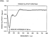
- the particle dispersion element 1 was irradiated with the YAG laser light, and wavelength dependency of a Faraday ellipticity of the particle dispersion element 1 at a room temperature was examined by using a Faraday effect measurement device. As a result thereof, results as shown in Fig. 12 were obtained.
- a loop shape of the hysteresis of the Faraday ellipticity corresponded to a loop shape of the magnetic hysteresis in Fig. 11A and Fig. 11B , which was measured by the SQUID.
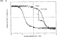
- the external magnetic field H 0 was set to +2.5 kOe (+1.99 ⁇ 10 5 A/m), and the particle dispersion element 1 was irradiated with pulsed YAG laser light of 8.1 mJ/pulse, and thus, the magnetization inversion of the particle dispersion element 1 was checked. Accordingly, it was possible to check that the magnetization inversion of the epsilon iron oxide particles was assisted even with pulsed light of 10 nanoseconds, and even in a case where the external magnetic field H 0 was decreased, the magnetization inversion was capable of being performed.
- the hysteresis was measured by increasing the external magnetic field H 0 , and then, by decreasing again the external magnetic field H 0 , and thus, it was possible to check that the loop was capable of being initialized to the same loop as that of the hysteresis before the light irradiation.
- the external magnetic field H 0 was set again to +2.5 kOe (+1.99 ⁇ 10 5 A/m), and the particle dispersion element 1 was irradiated with pulsed YAG laser light of 12.7 mJ/pulse, and thus, as shown in Fig. 14 , the magnetization inversion of the particle dispersion element 1 was checked.
- the external magnetic field H 0 was changed, the initial hysteresis before the light irradiation was set, and the external magnetic field H 0 was set again to +2.5 kOe (+1.99 ⁇ 10 5 A/m), and the particle dispersion element 1 was irradiated with pulsed YAG laser light of 16.0 mJ/pulse, and thus, as shown in Fig. 15 , the magnetization inversion of the particle dispersion element 1 was checked.
- the case of recording information in the particle dispersion element 1 by the application of the external magnetic field and the irradiation of light having predetermined intensity has been described as the recording of information in the magnetic recording medium, but the invention is not limited thereto, and as shown in Fig. 13 , Fig. 14 , and Fig. 15 , described above, information may be recorded to the particle dispersion element 1 in a multi-valued manner (in a state in which binary or more multiple values can be identified by a multistage magnetization state) by changing the intensity of light in accordance with information to be recorded, at the time of recording information in the particle dispersion element 1 by the application of the external magnetic field and the irradiation of light.
- a reproduction device 15 includes a detection unit 16, an information reproduction unit 17, and a display unit 18.
- the detection unit 16, for example, is a magnetic head, and is disposed to be close to or in contact with the recording surface of the particle dispersion element 1.
- the detection unit 16 scans on the particle dispersion element 1, and detects the magnetization of the particle dispersion element 1, and outputs detection results that are obtained to the information reproduction unit 17.
- the information reproduction unit 17 reproduces the information according to the intensity of the magnetization, on the basis of the intensity of the magnetization that is detected from the particle dispersion element 1, and allows the display unit 18 to display the information.
- the information is recorded in the particle dispersion element 1 by the irradiation of light and the application of the external magnetic field, in a case where the intensity of light decreases, the magnetization inversion amount also decreases.
- the reproduction device 15 when the reproduction is performed by the reproduction device 15, the intensity of the magnetization that is detected from the particle dispersion element 1 also decreases.
- multi-valued information is recorded to the particle dispersion element 1 by adjusting the intensity of the light when the information is recorded in the particle dispersion element 1.
- the magnetization of the particle dispersion element 1 is detected by the reproduction device 15, and thus, the multi-valued information can be reproduced from a difference in the intensity of the magnetization at the time of being detected.
- the epsilon iron oxide particles used as a magnetic material are capable of absorbing terahertz light in a millimeter wave (30 GHz to 300 GHz) region by a resonance phenomenon of the magnetization.
- the epsilon iron oxide particles are irradiated with the terahertz light, and thus, a high-speed movement of the magnetization is induced.
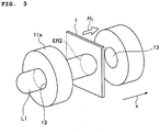
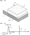
- Fig. 17 illustrates a high-speed response element 25 in which a magnetization state responds at a high speed in accordance with the irradiation of the terahertz light.
- the magnetization 3 is directed in the initial orientation direction x1.
- Fig. 18 in a case where the high-speed response element 25 is irradiated with terahertz light L2, a precession movement of the magnetization 3 in the region ER2 to which the terahertz light L2 is applied is induced, and the magnetization state is changed.
- Such a change in the magnetization state occurs in conformance with a timing when the terahertz light L2 is applied. Specifically, the precession movement of the magnetization 3 is induced immediately after the high-speed response element 25 starts to be irradiated with the terahertz light L2, and the magnetization state immediately starts to change. In addition, in a case where the irradiation of the terahertz light L2 to the high-speed response element 25 ends, the precession movement of the magnetization 3 immediately stops, and the magnetization state returns to the initial state.
- the high-speed response element 25 contains the epsilon iron oxide particles, and the magnetization state responds in conformance with a timing when the terahertz light L2 is applied. Accordingly, the magnetization state responds at a high speed in conformance with a timing when the terahertz light L2 is applied, and thus, the high-speed response element 25 can be applied to various circuit elements in which high-speed response is required.
- the terahertz light may be terahertz light that is continuously applied to the high-speed response element 25, in addition to the pulsed terahertz light (hereinafter, referred to as pulsed terahertz light).
- the high-speed response element 25 was irradiated with the pulsed terahertz light L2, the responsiveness of the magnetization with respect to the pulsed terahertz light L2 was examined.
- the validation test epsilon iron oxide particles containing ⁇ -Fe 2 O 3 crystals were used as a magnetic material, and the high-speed response element 25 was prepared in the same procedure as that of "(2) Particle Dispersion Element Containing Epsilon Iron Oxide Particles" described above.
- the pulsed terahertz light L2 was applied toward one surface of the high-speed response element 25. Note that, the pulsed terahertz light L2 applied to the high-speed response element 25 was set to a pulsed signal S1.
- pulsed terahertz light L2 having high intensity was used as the pulsed terahertz light L2, and the response of the magnetization was observed by using a Faraday effect measurement device.
- the pulsed terahertz light L2 used in the measurement had a maximum peak amplitude of 400 kV/cm.
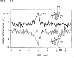
- a Faraday rotation angle was examined with respect to each of a case where a high-speed response element 31a was provided such that the magnetization is directed in a direction opposite to an irradiation direction of the pulsed terahertz light L2 and a case where a high-speed response element 31b was provided such that the magnetization was directed in the irradiation direction of the pulsed terahertz light L2.
- high-speed spectrometry of the Faraday rotation angle was performed by a pump-probe method according to terahertz excitation and optical Faraday detection.
- the signal S1 of the pulsed terahertz light L2, a signal S4 obtained by squaring an electric field of the pulsed terahertz light L2, a Faraday signal S5 of the high-speed response element 31a obtained at this time, and a Faraday signal S6 of the high-speed response element 31b were arranged on a time axis, and thus, results as shown in Fig. 21 were obtained.
- the particle dispersion element is applied as the magnetic recording medium, and for example, various magnetic recording media such as a magnetic tape or a magnetic disk may be applied.
- the magnetic field application unit 11 including the first coil portion 11a and the second coil portion 11b that generate the external magnetic field H 0 by allowing a current to flow is applied, but the invention is not limited thereto, and a magnet or the like may be used as the magnetic field application unit. Further, it is not necessary that an electromagnetic wave is perpendicularly applied to the recording surface of the magnetic recording medium, and the electromagnetic wave may be applied from various angles.
Landscapes
- Engineering & Computer Science (AREA)
- Power Engineering (AREA)
- Hard Magnetic Materials (AREA)
- Magnetic Record Carriers (AREA)
- Manufacturing Of Magnetic Record Carriers (AREA)
- Recording Or Reproducing By Magnetic Means (AREA)
- Compounds Of Iron (AREA)
- Liquid Crystal (AREA)
Applications Claiming Priority (2)
| Application Number | Priority Date | Filing Date | Title |
|---|---|---|---|
| JP2018065699 | 2018-03-29 | ||
| PCT/JP2018/044691 WO2019187356A1 (ja) | 2018-03-29 | 2018-12-05 | 記録方法、記録装置、再生方法、再生装置、及び、高速応答素子 |
Publications (2)
| Publication Number | Publication Date |
|---|---|
| EP3779986A1 true EP3779986A1 (de) | 2021-02-17 |
| EP3779986A4 EP3779986A4 (de) | 2022-03-30 |
Family
ID=68058683
Family Applications (1)
| Application Number | Title | Priority Date | Filing Date |
|---|---|---|---|
| EP18911675.9A Pending EP3779986A4 (de) | 2018-03-29 | 2018-12-05 | Aufzeichnungsverfahren, aufzeichnungsvorrichtung, wiedergabeverfahren, wiedergabevorrichtung und hochgeschwindigkeitsreaktionselement |
Country Status (7)
| Country | Link |
|---|---|
| US (1) | US11315595B2 (de) |
| EP (1) | EP3779986A4 (de) |
| JP (2) | JP7036323B2 (de) |
| KR (1) | KR102342130B1 (de) |
| CN (1) | CN111902867B (de) |
| TW (1) | TWI805678B (de) |
| WO (1) | WO2019187356A1 (de) |
Families Citing this family (1)
| Publication number | Priority date | Publication date | Assignee | Title |
|---|---|---|---|---|
| JP7656287B2 (ja) * | 2020-05-26 | 2025-04-03 | 国立大学法人東北大学 | 鉄系酸化物磁性粉およびその製造方法 |
Family Cites Families (47)
| Publication number | Priority date | Publication date | Assignee | Title |
|---|---|---|---|---|
| JPS61104442A (ja) * | 1984-10-24 | 1986-05-22 | Nec Corp | 光磁気記録媒体と光磁気記録方法 |
| JPH0721892B2 (ja) * | 1985-02-14 | 1995-03-08 | 日本電気株式会社 | 光磁気記録方法 |
| JPH035932A (ja) * | 1989-06-02 | 1991-01-11 | Nippon Hoso Kyokai <Nhk> | 記録媒体、記録再生装置および記録方式 |
| JPH04222946A (ja) * | 1990-12-26 | 1992-08-12 | Sony Corp | 光磁気用薄膜ヘッド |
| JP3130094B2 (ja) | 1991-10-31 | 2001-01-31 | ティーディーケイ株式会社 | ダイヤモンド様薄膜保護膜を有する金型 |
| JPH05314412A (ja) * | 1992-05-07 | 1993-11-26 | Fujitsu Ltd | 磁気記録再生方法 |
| US6061307A (en) * | 1994-05-10 | 2000-05-09 | Hitachi Maxell, Ltd. | Magneto-optical recording medium having a plurality of magnetic layers |
| JPH08259237A (ja) * | 1995-03-22 | 1996-10-08 | Sakai Chem Ind Co Ltd | 非磁性酸化鉄粉末及びその製造方法 |
| US5923625A (en) * | 1995-07-13 | 1999-07-13 | Hitachi Maxell, Ltd. | Magneto-optical recording medium and method for recording and reproduction thereon |
| CN1207822A (zh) * | 1995-12-20 | 1999-02-10 | 日立马库塞鲁株式会社 | 磁光记录介质及其再生方法 |
| JP3491655B2 (ja) * | 1996-03-13 | 2004-01-26 | ソニー株式会社 | 記録装置および方法 |
| JP4366551B2 (ja) * | 1999-08-03 | 2009-11-18 | 戸田工業株式会社 | 磁気記録媒体の非磁性下地層用針状非磁性粒子粉末並びに磁気記録媒体 |
| JP3792406B2 (ja) * | 1998-08-14 | 2006-07-05 | 株式会社リコー | 高密度磁気記録再生方法および高密度磁気記録媒体 |
| JP2000285544A (ja) * | 1999-03-30 | 2000-10-13 | Sharp Corp | 光磁気記録再生装置 |
| JP2001216630A (ja) * | 2000-01-28 | 2001-08-10 | Hitachi Maxell Ltd | 磁気記録媒体、その製造方法及び磁気ディスク装置 |
| SG116437A1 (en) * | 2000-12-22 | 2005-11-28 | Fuji Photo Film Co Ltd | Information recording medium, information recording and reproducing method and manufacturing method of information recording medium. |
| JP2002298465A (ja) * | 2001-03-30 | 2002-10-11 | Nihon University | 多値記録再生方法及び装置 |
| JP2004005874A (ja) * | 2001-08-07 | 2004-01-08 | Mitsubishi Chemicals Corp | 磁気記録媒体の磁化パターン形成方法及び製造方法、磁化パターン形成装置、磁気記録媒体、並びに磁気記録装置 |
| JP2004087041A (ja) * | 2002-08-28 | 2004-03-18 | Nihon University | 記録媒体、記録装置及び方法 |
| JP4223769B2 (ja) * | 2002-08-30 | 2009-02-12 | 富士通株式会社 | 測定装置 |
| JP3886889B2 (ja) * | 2002-11-20 | 2007-02-28 | 富士通株式会社 | 光磁気記録媒体および光磁気記録媒体の製造方法 |
| JP2005222669A (ja) * | 2004-01-05 | 2005-08-18 | Fujitsu Ltd | 磁気記録媒体および磁気記憶装置 |
| JP2005209290A (ja) * | 2004-01-23 | 2005-08-04 | Hitachi Ltd | 熱磁気転写型磁気記録方式および磁気ディスク装置 |
| CN100578695C (zh) * | 2005-12-19 | 2010-01-06 | Tdk株式会社 | 铁氧体磁性材料 |
| JP4728916B2 (ja) * | 2006-08-31 | 2011-07-20 | 国立大学法人 東京大学 | 磁性材料 |
| JP5124825B2 (ja) | 2006-09-08 | 2013-01-23 | 国立大学法人 東京大学 | ε酸化鉄系の磁性材料 |
| JP5142354B2 (ja) | 2007-01-16 | 2013-02-13 | 国立大学法人 東京大学 | ε−Fe2O3結晶の製法 |
| US8335037B2 (en) * | 2007-10-24 | 2012-12-18 | The University Of Tokyo | Millimeter wave band nonreciprocal device |
| WO2010150853A1 (ja) * | 2009-06-24 | 2010-12-29 | 国立大学法人東京大学 | 磁性薄膜の製造方法、磁性薄膜及び磁性体 |
| JP5297299B2 (ja) * | 2009-08-18 | 2013-09-25 | 日本放送協会 | 磁気光学特性測定装置及び磁気光学特性の測定方法 |
| JP2011070744A (ja) * | 2009-09-28 | 2011-04-07 | Showa Denko Kk | 磁気記録媒体の検査方法及び製造方法 |
| JP5668236B2 (ja) * | 2010-09-14 | 2015-02-12 | セイコーインスツル株式会社 | 近接場光ヘッドの製造方法、近接場光ヘッド、及び情報記録再生装置 |
| JP5804487B2 (ja) * | 2010-11-08 | 2015-11-04 | セイコーインスツル株式会社 | 記録ヘッド、記録ヘッドの製造方法、及び情報記録再生装置 |
| US9660874B2 (en) | 2012-12-13 | 2017-05-23 | Level 3 Communications, Llc | Devices and methods supporting content delivery with delivery services having dynamically configurable log information |
| JP5802224B2 (ja) * | 2013-01-31 | 2015-10-28 | 富士フイルム株式会社 | 磁気記録媒体 |
| JP5799035B2 (ja) * | 2013-02-05 | 2015-10-21 | 富士フイルム株式会社 | 塗布型磁気記録媒体、磁気記録装置、および磁気記録方法 |
| CN106463224B (zh) * | 2014-06-18 | 2018-11-06 | 国立大学法人东京大学 | 氧化铁纳米磁粉及其制造方法 |
| US10204651B2 (en) * | 2014-06-24 | 2019-02-12 | Sony Corporation | Magnetic recording medium having cubic ferrite or e-phase iron oxide magnetic particles |
| JP5966064B1 (ja) * | 2014-09-24 | 2016-08-10 | Dowaエレクトロニクス株式会社 | 鉄系酸化物磁性粒子粉および鉄系酸化物磁性粒子粉の製造方法 |
| JP6010181B2 (ja) * | 2015-01-09 | 2016-10-19 | Dowaエレクトロニクス株式会社 | 鉄系酸化物磁性粒子粉およびその製造方法並びに塗料および磁気記録媒体 |
| JP6756483B2 (ja) | 2015-01-19 | 2020-09-16 | 国立大学法人 東京大学 | ε酸化鉄を含む配向体とその製造方法、並びに製造装置 |
| US9384774B1 (en) * | 2015-03-23 | 2016-07-05 | Western Digital Technologies, Inc. | Data storage device calibrating a laser power for heat assisted magnetic recording based on slope of quality metric |
| WO2017094752A1 (ja) * | 2015-11-30 | 2017-06-08 | 国立大学法人 東京大学 | 配向体、その製造方法、その製造装置、及び磁気記録媒体 |
| US20190035521A1 (en) | 2016-01-20 | 2019-01-31 | The University Of Tokyo | Magnetic substance, magnetic toner, and magnetic powder |
| JP6189517B2 (ja) * | 2016-02-01 | 2017-08-30 | 日立マクセル株式会社 | 磁気記録媒体 |
| JP6632465B2 (ja) | 2016-04-28 | 2020-01-22 | 富士フイルム株式会社 | マイクロ波アシスト記録用磁気記録媒体および磁気記録装置 |
| CN105921128A (zh) * | 2016-05-10 | 2016-09-07 | 吴迪 | 一种磁性水凝胶的制备方法 |
-
2018
- 2018-12-05 WO PCT/JP2018/044691 patent/WO2019187356A1/ja not_active Ceased
- 2018-12-05 JP JP2020509625A patent/JP7036323B2/ja active Active
- 2018-12-05 CN CN201880091924.3A patent/CN111902867B/zh active Active
- 2018-12-05 KR KR1020207026154A patent/KR102342130B1/ko active Active
- 2018-12-05 EP EP18911675.9A patent/EP3779986A4/de active Pending
-
2019
- 2019-01-15 TW TW108101466A patent/TWI805678B/zh active
-
2020
- 2020-09-28 US US17/035,077 patent/US11315595B2/en active Active
-
2021
- 2021-12-22 JP JP2021208644A patent/JP7116966B2/ja active Active
Also Published As
| Publication number | Publication date |
|---|---|
| JP2022040165A (ja) | 2022-03-10 |
| WO2019187356A1 (ja) | 2019-10-03 |
| CN111902867B (zh) | 2022-07-29 |
| US20210027806A1 (en) | 2021-01-28 |
| KR102342130B1 (ko) | 2021-12-21 |
| JP7036323B2 (ja) | 2022-03-15 |
| KR20200132868A (ko) | 2020-11-25 |
| TW202004739A (zh) | 2020-01-16 |
| EP3779986A4 (de) | 2022-03-30 |
| JP7116966B2 (ja) | 2022-08-12 |
| CN111902867A (zh) | 2020-11-06 |
| US11315595B2 (en) | 2022-04-26 |
| TWI805678B (zh) | 2023-06-21 |
| JPWO2019187356A1 (ja) | 2021-02-12 |
Similar Documents
| Publication | Publication Date | Title |
|---|---|---|
| Li et al. | Chiral domain walls of Mn3Sn and their memory | |
| Oberdick et al. | Spin canting across core/shell Fe3O4/MnxFe3− xO4 nanoparticles | |
| US11462242B2 (en) | Magnetic tape having characterized magnetic layer and magnetic recording and reproducing device | |
| Hu et al. | Unusual dynamic susceptibility arising from soft ferromagnetic domains in MnBi8Te13 and Sb-doped MnBi 2 n Te 3 n+ 1 (n= 2, 3) | |
| US11315595B2 (en) | Recording method, recording device, reproduction method, reproduction device, and high-speed response element | |
| Papusoi et al. | Measurements of Gilbert damping parameter α for CoPt-based and CoFe-based films for magnetic recording applications | |
| Shelton et al. | Magnetometry in a diamond anvil cell using nitrogen vacancy centers in a nanodiamond ensemble | |
| Nissen et al. | Magnetic coupling of vortices in a two-dimensional lattice | |
| Miura et al. | Observation of the magnetic-field-induced semimetal-semiconductor transition in Bi under megagauss fields | |
| Khan et al. | Correlations of magnetic microstructure and anisotropy with noise spectra for CoNi and CoCrTa thin film media | |
| Brandt et al. | Size-dependent magnetization switching characteristics and spin wave modes of FePt nanostructures | |
| US11574652B2 (en) | Recording device and recording method | |
| RU2168193C2 (ru) | Магнитооптический преобразователь, способ выращивания пленки, способ визуализации неоднородного магнитного поля (варианты) и устройство для его осуществления | |
| Kamzin | Surface magnetism of Sc-substituted Ba-M hexaferrites | |
| Andalouci et al. | Magnetic and magneto-optical properties of assembly of nanodots obtained from solid-state dewetting of ultrathin cobalt layer | |
| Metternich et al. | Defects in magnetic domain walls after single-shot all-optical switching | |
| Nair et al. | Enhanced shape anisotropy and magneto-optical birefringence by high energy ball milling in NixFe1− xFe2O4 ferrofluids | |
| NL7909181A (nl) | Werkwijze voor het aanschouwelijk maken en registreren van een zichtbare voorstelling van een krachtveld op een drager. | |
| Poulose et al. | Characterization of Nontoxic Nanomaterials for Biological Applications | |
| Igarashi et al. | Analysis on bimodal complex permeability spectrum of a noise suppression sheet and single constituent flakes | |
| JP2009053103A (ja) | 塗膜層の評価方法 | |
| Riley | The Effects of Structural Confinement and Thermal Profiles on Propagating Spin Waves | |
| von Geisau et al. | Photothermal characterization of microwave magnetic excitations | |
| Van Keuren | Light scattering studies of magnetic particle dispersions | |
| Jiang | Structural and magnetic properties of ultrathin cobalt films on copper (001) surfaces: A combined HRLEED and SMOKE study |
Legal Events
| Date | Code | Title | Description |
|---|---|---|---|
| STAA | Information on the status of an ep patent application or granted ep patent |
Free format text: STATUS: THE INTERNATIONAL PUBLICATION HAS BEEN MADE |
|
| PUAI | Public reference made under article 153(3) epc to a published international application that has entered the european phase |
Free format text: ORIGINAL CODE: 0009012 |
|
| STAA | Information on the status of an ep patent application or granted ep patent |
Free format text: STATUS: REQUEST FOR EXAMINATION WAS MADE |
|
| 17P | Request for examination filed |
Effective date: 20200918 |
|
| AK | Designated contracting states |
Kind code of ref document: A1 Designated state(s): AL AT BE BG CH CY CZ DE DK EE ES FI FR GB GR HR HU IE IS IT LI LT LU LV MC MK MT NL NO PL PT RO RS SE SI SK SM TR |
|
| AX | Request for extension of the european patent |
Extension state: BA ME |
|
| RAP3 | Party data changed (applicant data changed or rights of an application transferred) |
Owner name: THE UNIVERSITY OF TOKYO Owner name: OSAKA UNIVERSITY Owner name: FUJIFILM CORPORATION |
|
| DAV | Request for validation of the european patent (deleted) | ||
| DAX | Request for extension of the european patent (deleted) | ||
| RIC1 | Information provided on ipc code assigned before grant |
Ipc: H01F 1/113 20060101ALI20211119BHEP Ipc: G11B 5/706 20060101ALI20211119BHEP Ipc: G11B 5/02 20060101AFI20211119BHEP |
|
| A4 | Supplementary search report drawn up and despatched |
Effective date: 20220228 |
|
| RIC1 | Information provided on ipc code assigned before grant |
Ipc: H01F 1/113 20060101ALI20220222BHEP Ipc: G11B 5/706 20060101ALI20220222BHEP Ipc: G11B 5/02 20060101AFI20220222BHEP |
|
| STAA | Information on the status of an ep patent application or granted ep patent |
Free format text: STATUS: EXAMINATION IS IN PROGRESS |
|
| 17Q | First examination report despatched |
Effective date: 20250717 |