EP3779477A2 - Schnelle over-the-air-testplattform für produktionslinien - Google Patents
Schnelle over-the-air-testplattform für produktionslinien Download PDFInfo
- Publication number
- EP3779477A2 EP3779477A2 EP20191147.6A EP20191147A EP3779477A2 EP 3779477 A2 EP3779477 A2 EP 3779477A2 EP 20191147 A EP20191147 A EP 20191147A EP 3779477 A2 EP3779477 A2 EP 3779477A2
- Authority
- EP
- European Patent Office
- Prior art keywords
- antenna array
- dut
- ota
- production line
- rapid
- Prior art date
- Legal status (The legal status is an assumption and is not a legal conclusion. Google has not performed a legal analysis and makes no representation as to the accuracy of the status listed.)
- Granted
Links
Images


Classifications
-
- H—ELECTRICITY
- H01—ELECTRIC ELEMENTS
- H01P—WAVEGUIDES; RESONATORS, LINES, OR OTHER DEVICES OF THE WAVEGUIDE TYPE
- H01P5/00—Coupling devices of the waveguide type
- H01P5/02—Coupling devices of the waveguide type with invariable factor of coupling
- H01P5/022—Transitions between lines of the same kind and shape, but with different dimensions
- H01P5/028—Transitions between lines of the same kind and shape, but with different dimensions between strip lines
-
- H—ELECTRICITY
- H01—ELECTRIC ELEMENTS
- H01Q—ANTENNAS, i.e. RADIO AERIALS
- H01Q19/00—Combinations of primary active antenna elements and units with secondary devices, e.g. with quasi-optical devices, for giving the antenna a desired directional characteristic
- H01Q19/10—Combinations of primary active antenna elements and units with secondary devices, e.g. with quasi-optical devices, for giving the antenna a desired directional characteristic using reflecting surfaces
- H01Q19/104—Combinations of primary active antenna elements and units with secondary devices, e.g. with quasi-optical devices, for giving the antenna a desired directional characteristic using reflecting surfaces using a substantially flat reflector for deflecting the radiated beam, e.g. periscopic antennas
-
- G—PHYSICS
- G01—MEASURING; TESTING
- G01R—MEASURING ELECTRIC VARIABLES; MEASURING MAGNETIC VARIABLES
- G01R29/00—Arrangements for measuring or indicating electric quantities not covered by groups G01R19/00 - G01R27/00
- G01R29/08—Measuring electromagnetic field characteristics
- G01R29/10—Radiation diagrams of antennas
-
- G—PHYSICS
- G01—MEASURING; TESTING
- G01R—MEASURING ELECTRIC VARIABLES; MEASURING MAGNETIC VARIABLES
- G01R31/00—Arrangements for testing electric properties; Arrangements for locating electric faults; Arrangements for electrical testing characterised by what is being tested not provided for elsewhere
- G01R31/28—Testing of electronic circuits, e.g. by signal tracer
- G01R31/282—Testing of electronic circuits specially adapted for particular applications not provided for elsewhere
- G01R31/2822—Testing of electronic circuits specially adapted for particular applications not provided for elsewhere of microwave or radiofrequency circuits
-
- H—ELECTRICITY
- H01—ELECTRIC ELEMENTS
- H01P—WAVEGUIDES; RESONATORS, LINES, OR OTHER DEVICES OF THE WAVEGUIDE TYPE
- H01P3/00—Waveguides; Transmission lines of the waveguide type
- H01P3/02—Waveguides; Transmission lines of the waveguide type with two longitudinal conductors
- H01P3/08—Microstrips; Strip lines
- H01P3/081—Microstriplines
- H01P3/082—Multilayer dielectric
-
- H—ELECTRICITY
- H01—ELECTRIC ELEMENTS
- H01P—WAVEGUIDES; RESONATORS, LINES, OR OTHER DEVICES OF THE WAVEGUIDE TYPE
- H01P3/00—Waveguides; Transmission lines of the waveguide type
- H01P3/02—Waveguides; Transmission lines of the waveguide type with two longitudinal conductors
- H01P3/08—Microstrips; Strip lines
- H01P3/088—Stacked transmission lines
-
- H—ELECTRICITY
- H01—ELECTRIC ELEMENTS
- H01P—WAVEGUIDES; RESONATORS, LINES, OR OTHER DEVICES OF THE WAVEGUIDE TYPE
- H01P5/00—Coupling devices of the waveguide type
- H01P5/02—Coupling devices of the waveguide type with invariable factor of coupling
-
- H—ELECTRICITY
- H01—ELECTRIC ELEMENTS
- H01Q—ANTENNAS, i.e. RADIO AERIALS
- H01Q13/00—Waveguide horns or mouths; Slot antennas; Leaky-waveguide antennas; Equivalent structures causing radiation along the transmission path of a guided wave
- H01Q13/02—Waveguide horns
-
- H—ELECTRICITY
- H01—ELECTRIC ELEMENTS
- H01Q—ANTENNAS, i.e. RADIO AERIALS
- H01Q15/00—Devices for reflection, refraction, diffraction or polarisation of waves radiated from an antenna, e.g. quasi-optical devices
- H01Q15/02—Refracting or diffracting devices, e.g. lens, prism
- H01Q15/06—Refracting or diffracting devices, e.g. lens, prism comprising plurality of wave-guiding channels of different length
-
- H—ELECTRICITY
- H01—ELECTRIC ELEMENTS
- H01Q—ANTENNAS, i.e. RADIO AERIALS
- H01Q15/00—Devices for reflection, refraction, diffraction or polarisation of waves radiated from an antenna, e.g. quasi-optical devices
- H01Q15/14—Reflecting surfaces; Equivalent structures
-
- H—ELECTRICITY
- H01—ELECTRIC ELEMENTS
- H01Q—ANTENNAS, i.e. RADIO AERIALS
- H01Q19/00—Combinations of primary active antenna elements and units with secondary devices, e.g. with quasi-optical devices, for giving the antenna a desired directional characteristic
- H01Q19/06—Combinations of primary active antenna elements and units with secondary devices, e.g. with quasi-optical devices, for giving the antenna a desired directional characteristic using refracting or diffracting devices, e.g. lens
-
- H—ELECTRICITY
- H01—ELECTRIC ELEMENTS
- H01Q—ANTENNAS, i.e. RADIO AERIALS
- H01Q19/00—Combinations of primary active antenna elements and units with secondary devices, e.g. with quasi-optical devices, for giving the antenna a desired directional characteristic
- H01Q19/10—Combinations of primary active antenna elements and units with secondary devices, e.g. with quasi-optical devices, for giving the antenna a desired directional characteristic using reflecting surfaces
- H01Q19/18—Combinations of primary active antenna elements and units with secondary devices, e.g. with quasi-optical devices, for giving the antenna a desired directional characteristic using reflecting surfaces having two or more spaced reflecting surfaces
- H01Q19/185—Combinations of primary active antenna elements and units with secondary devices, e.g. with quasi-optical devices, for giving the antenna a desired directional characteristic using reflecting surfaces having two or more spaced reflecting surfaces wherein the surfaces are plane
-
- H—ELECTRICITY
- H01—ELECTRIC ELEMENTS
- H01Q—ANTENNAS, i.e. RADIO AERIALS
- H01Q21/00—Antenna arrays or systems
- H01Q21/29—Combinations of different interacting antenna units for giving a desired directional characteristic
- H01Q21/293—Combinations of different interacting antenna units for giving a desired directional characteristic one unit or more being an array of identical aerial elements
-
- H—ELECTRICITY
- H04—ELECTRIC COMMUNICATION TECHNIQUE
- H04B—TRANSMISSION
- H04B17/00—Monitoring; Testing
-
- H—ELECTRICITY
- H04—ELECTRIC COMMUNICATION TECHNIQUE
- H04B—TRANSMISSION
- H04B17/00—Monitoring; Testing
- H04B17/0082—Monitoring; Testing using service channels; using auxiliary channels
- H04B17/0085—Monitoring; Testing using service channels; using auxiliary channels using test signal generators
-
- G—PHYSICS
- G01—MEASURING; TESTING
- G01R—MEASURING ELECTRIC VARIABLES; MEASURING MAGNETIC VARIABLES
- G01R29/00—Arrangements for measuring or indicating electric quantities not covered by groups G01R19/00 - G01R27/00
- G01R29/08—Measuring electromagnetic field characteristics
- G01R29/0864—Measuring electromagnetic field characteristics characterised by constructional or functional features
- G01R29/0878—Sensors; antennas; probes; detectors
-
- G—PHYSICS
- G01—MEASURING; TESTING
- G01R—MEASURING ELECTRIC VARIABLES; MEASURING MAGNETIC VARIABLES
- G01R31/00—Arrangements for testing electric properties; Arrangements for locating electric faults; Arrangements for electrical testing characterised by what is being tested not provided for elsewhere
- G01R31/28—Testing of electronic circuits, e.g. by signal tracer
- G01R31/302—Contactless testing
- G01R31/3025—Wireless interface with the DUT
-
- H—ELECTRICITY
- H01—ELECTRIC ELEMENTS
- H01Q—ANTENNAS, i.e. RADIO AERIALS
- H01Q3/00—Arrangements for changing or varying the orientation or the shape of the directional pattern of the waves radiated from an antenna or antenna system
- H01Q3/26—Arrangements for changing or varying the orientation or the shape of the directional pattern of the waves radiated from an antenna or antenna system varying the relative phase or relative amplitude of energisation between two or more active radiating elements; varying the distribution of energy across a radiating aperture
- H01Q3/267—Phased-array testing or checking devices
Definitions
- the present disclosure generally relates to production line test platforms. More specifically, the present disclosure relates to rapid millimeter wave (mmWave) fifth generation (5G) mobile communication over-the-air (OTA) production line test platforms.
- mmWave millimeter wave
- 5G fifth generation
- OTA mobile communication over-the-air
- 5G New Radio has re-defined a new frequency spectrum under the following three circumstances: enhanced Mobile Broadband (eMBB), Ultra-Reliable and Low Latency Communications (URLLC) and massive Machine Type Communications (mMTC).
- eMBB enhanced Mobile Broadband
- URLLC Ultra-Reliable and Low Latency Communications
- mMTC massive Machine Type Communications
- Frequency Range 2 (FR2) uses millimeter waves (mmWave) with frequencies range from 24250 MHz to 52600 MHz in 3GPP standard.
- mmWave millimeter waves
- beamforming technique has been employed in antenna arrays to achieve higher equivalent isotropically radiated power (EIRP) and wider coverage.
- antenna arrays can be integrated into RF modules.
- a high density module is called an Antennas in Package (AiP) module and can be mass produced.
- AiP Antennas in Package
- the present disclosure provides a rapid over-the-air (OTA) production line test platform, which may include: an antenna array for transmitting a test beam in a plurality of transmitting directions; an electromagnetic wave guiding device for guiding the test beam; a test machine to be loaded with a device under test (DUT) for controlling the DUT to receive the guided test beam from a plurality of receiving directions; and a controller electrically connected with the test machine and the antenna array for calculating an antenna radiation pattern of the DUT based on at least one power received from the plurality of receiving directions corresponding to the DUT and a transmitting power of the antenna array.
- OTA over-the-air
- the rapid OTA production line test platform may further include: two reflecting plates disposed opposite to each other and between the DUT and the antenna array, wherein the test beam propagates between the antenna array, the DUT and the two reflecting plates to enable an OTA beam test of the DUT.
- the rapid OTA production line test platform may further include a first horn antenna array and a second horn antenna array arranged and focus around a first center and a second center, respectively; and a plurality of bending waveguides connected between the first horn antenna array and the second horn antenna array, wherein the antenna array at the first center sequentially transmits the test beam with beamforming towards the first horn antenna array, and the DUT capable of beamforming at the second center receives the test beam after being guided by the plurality of bending waveguides to implement the OTA beam test of the DUT.
- the rapid OTA production line test platform may further include a three dimensional (3D) elliptic curve, wherein a plane of the antenna array and a plane of the DUT capable of beamforming are perpendicular to each other, and the test beam is transmitted with beamforming by the antenna array at a first focal point of the 3D elliptic curve, then reflected by the 3D elliptic curve and received by the DUT at a second focal point of the 3D elliptic curve to implement the OTA beam test of the DUT.
- 3D three dimensional
- an objective of the present disclosure is to provide a rapid over-the-air (OTA) production line test platform applicable to millimeter wave (mmWave) fifth generation (5G) mobile communication.
- OTA over-the-air
- mmWave millimeter wave
- 5G fifth generation
- a first component angle ⁇ is the angle of the projection of a transmitting vector on a xz plane with respect to the normal direction (z axis)
- a second component angle ⁇ is the angle of the projection of the transmitting direction of the electromagnetic wave on a yz plane with respect to the normal direction (z axis).
- the signal strength of a signal source (i.e., transmitting end) is represented as Ps, which varies with the first component angle ⁇ and the second component angle ⁇ .
- Ps the signal strength of a signal source
- the contour lines are not perfect circles, but rather the strengths of the transmitting signals may vary slightly with differences in the two component angles. This is a characteristic of antenna arrays.
- the signal strength of a signal source can be represented as P S ( ⁇ , ⁇ ), and the path loss can be represented as P L .
- path loss is a function of the path length R
- path loss can be essentially represented as P L (R).
- the noise signal strength at the receiving end i.e., the DUT
- P N is typically set as a constant for the same DUT.
- the noise signal strength is usually frequency-specific and the environment is assumed to be unchanged (in practice, however, the noise signal strength may still vary with frequency and the environment).
- the gain at the receiving end varies with the first component angle ⁇ and the second component angle ⁇ of the directional receiving angle (similar to the signal strength of the signal source)
- the gain at the receiving end can be expressed as G R ( ⁇ , ⁇ )
- the gain G R ( ⁇ , ⁇ ) at the receiving end can be obtained by measurement and calculation.
- the antenna radiation pattern of the DUT can then be obtained by a quantitative grid chart of a power level scan. In some applications, the energy can be computed directly.
- the DUT in the case that the DUT is an antenna array instead of a single antenna and the signal source is also an antenna array, the signal source emits mmWave to the DUT with a first component angle ⁇ m and a second component angle ⁇ n , then the DUT will also need to correspondingly switch to ⁇ m and ⁇ n , i.e., ( ⁇ m , ⁇ n ) .
- the signal source emits mmWave to the DUT with a first component angle ⁇ m and a second component angle ⁇ n , then the DUT will also need to correspondingly switch to ⁇ x and ⁇ y , i.e., ( ⁇ x , ⁇ y ), wherein x is m-2 ⁇ m+2, and y is n-2 ⁇ n+2, but the present disclosure is not limited as such.
- the SNRs received by the receiving ends can all be obtained by measurement and calculation (as mentioned above) in order to obtain the antenna radiation patterns of the DUTs via quantitative grid charts of a power level scan.
- the signal strength received by the DUT can be calculated directly and the antenna radiation pattern can be obtained using the equation (1) above.
- measuring and calculating the signal strength (power) received by the receiving end is substantially equivalent to the method realized using the SNR above.
- the notion of determining an antenna radiation pattern of a DUT from multiple directions is realized by an antenna array of known characteristics and an electromagnetic wave guiding device.
- the antenna array emits test beams in a plurality of transmitting directions, and the electromagnetic wave guiding device guides the test beams.
- a DUT is loaded on a test machine and controlled to receive the guided test beams from a plurality of receiving directions.
- a controller is electrically connected with the test machine and the antenna array for calculating the antenna radiation pattern of the DUT based on at least on the power received by the DUT at the plurality of receiving directions as well as the transmission power of the antenna array.
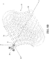
- FIGs. 3A to 3D are schematic diagrams depicting a rapid OTA production line test platform 1 in accordance with an embodiment of the present disclosure.
- the rapid OTA production line test platform 1 of the present disclosure for testing a device under test (DUT) 11 includes an antenna array 12, two reflecting plates 13 and a beamforming circuit 14.
- the electromagnetic wave guiding device substantially includes at least the two reflecting plates 13 above.
- the DUT 11 includes a beamforming function.
- the antenna array 12 is disposed opposite to the DUT 11 and emits test beams using a beamforming technique.
- the two reflecting plates 13 are disposed opposite to each other and between the DUT 11 and the antenna array 12. The OTA beam testing of the DUT 11 is conducted on beams reflected by the reflecting plates 13 at either side.
- the antenna array 12 is capable of beamforming, and the reflecting plates 13 at the two sides allows different beam directions of the DUT to be tested according to the needs. As shown in FIGs. 3A-3D , in an embodiment of the present disclosure, through direct transmission, single reflection, double reflections and triple reflections, 7 different sets of angles can be tested as can be seen in FIG. 4 .
- the path lengths of the present embodiment are related to the two component angles, so the path loss in this embodiment can be expressed as P L ( ⁇ , ⁇ ) .
- the gain of the DUT 11 i.e., the receiving end
- the gain of the DUT 11 at a specific receiving angle can be obtained based on the received SNR (or power) and other known parameters by measurements and calculations using the above equation (1), and data at various receiving angles can be collected to obtain the antenna radiation pattern of the DUT 11.
- the beamforming circuit 14 of the present disclosure can be connected to the antenna array 12. Since the beamforming circuit 14 includes a beamforming electronic scanning probe capable of 2D plane scan. Based on the requirements of the OTA tests, the beamforming circuit 14 can be connected to a network analyzer, signal generator, signal analyzer or a baseband equipment to perform other types of tests. Moreover, depending on the frequency band of the test equipment, an up/down frequency circuit with up/down frequency function can be added if needed.
- the rapid OTA production line test platform 2 of the present disclosure for testing a DUT 21 includes an antenna array 22, a first horn antenna array 23 a second horn antenna array 24 and a plurality of bending waveguides 25.
- the electromagnetic wave guiding device substantially includes at least the first horn antenna array 23, the second horn antenna array 24 and the plurality of bending waveguides 25.
- the DUT 21 is similarly capable of beamforming.
- the first horn antenna array 23 and the second horn antenna array 24 are arranged and focused around a first center C1 and a second center C2, respectively.
- the plurality of bending waveguides 25 are connected between the first horn antenna array 23 and the second horn antenna array 24.
- the antenna array 22 at the first center C1 sequentially emits signals towards the first horn antenna array 23, and the DUT 21 receives at the second center C2, so as to conduct OTA beam testing of the DUT 21.
- the first horn antenna array 23 and the second horn antenna array 24 of the present disclosure being arranged and focused around the two centers (i.e., the first center C1 and the second center C2) allows the antenna array 22 at the first center C1 to emit signals by beamforming techniques and the DUT 21 at the second center C2 (the other center) to beamformingly receive the signals through the first horn antenna array 23 and the second horn antenna array 24 coupled with the plurality of bending waveguides 25.
- the antenna array 22 acting as a transmitting end at the first center C1 can also be a receiving end, while the DUT 21 acting as a receiving end at the second center C2 can be a transmitting end. Therefore, transmitting and receiving radiation patterns can be measured.
- the resolution of the first horn antenna array 23 and the second horn antenna array 24 depends on the number of horn antennae in the first horn antenna array 23 and the second horn antenna array 24, the intervals between the horn antennae, and the distance between the DUT 21 and the first horn antenna array 23 and the second horn antenna array 24 as well as the distance between the antenna array 22 and the first horn antenna array 23 and the second horn antenna array 24.
- the plurality of bending waveguides 25 are used instead of the reflecting plates to guide the beamforming from the transmitting interface to the receiving interface at defined angles in order to obtain the measurements of beam peak power level and the phase.
- the path lengths in this embodiment are the path lengths of free space, i.e., the distance from the antenna array 22 of the transmitting end to the first horn antenna array 23 and the distance from the DUT 21 to the second horn antenna array 24.
- the plurality of bending waveguides 25 are assumed to have no path loss, so the path loss of the present embodiment can be set as a constant.
- the gain of the DUT 21 i.e., the receiving end
- the antenna radiation pattern of the DUT 21 can be obtained through a quantitative grid chart of a power level scan (as shown in FIG. 7 ).
- the path lengths in this embodiment can be represented by P L ( ⁇ , ⁇ ) .
- the path lengths of free space i.e., the distance from the antenna array 22 of the transmitting end to the first horn antenna array 23 and the distance from the DUT 21 to the second horn antenna array 24
- a compensation model needs to be introduced.
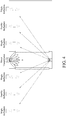
- FIG. 7 is a quantitative diagram depicting a power level scan of a S21 signal passing through a DUT (using 9 ⁇ 9 horn antenna arrays as an example).
- the transmitting end at the first center C1 sequentially transmits directional beamforming towards the 9 ⁇ 9 horn antenna arrays, and the receiving end at the second center C2 receives the beams at 0 degree of a fixed boresight along the positive Y axis.
- the present embodiment further includes a rotary motor 26 for rotating the DUT 21, thereby increasing the flexibility of its application.
- the present embodiment further includes a beamforming circuit (not shown) that can be connected to the antenna array 22.
- FIGs. 9A and 9B are schematic diagrams depicting a rotatable DUT 21. If the beam width of the DUT 21 is resolution ⁇ n+m (where n is an integer greater than or equal to 0, 0 ⁇ m ⁇ resolution, and m is an integer), then the DUT 21 can be made to direct its beams to the boresight of the transmitting end or at an angle that is an integer multiple of the resolution through the rotary motor 26 (e.g., such that the beams pointing to the opposite direction) to carry out measurements using the present embodiment.
- the directionality of the beams of the DUT 21 is -9 degrees rotation in the X-axis and -9 degrees rotation in the Z-axis
- the rotary motor 26 can rotate the antenna plane of the DUT 21 in the opposite direction to +9 degrees rotation in the X-axis and +9 degrees rotation in the Z-axis.
- the present embodiment employs horn antenna arrays arranged in circles combined with bending waveguides, such that the transmitting end and the receiving end can simultaneously perform 3D beamforming measurements.
- the present embodiment effectively reduces the time for beamforming verification and measurement, that is, by simply multiplying the beam switching time by the number of angle points required.
- the present embodiment requires only the use of bending waveguides and horn antenna arrays without the need for reflective planes or complex mechanical components, thereby effectively reducing the cost of measurement.
- FIG. 10 is a schematic diagram of a rapid OTA production line test platform 3 in accordance with an embodiment of present disclosure.
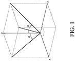
- the rapid OTA production line test platform 3 of the present disclosure for testing a DUT 31 includes an antenna array 32 and a 3D elliptic curve 33.
- the DUT 31 is capable of beamforming.
- the plane of the DUT 31 is perpendicular to the plane of the antenna array 32.
- the antenna array 32 is disposed at a second focal point F2 of the 3D elliptic curve 33 and emits beams by beamforming techniques, while the DUT 31 receives signals at a first focal point F1 of the 3D elliptic curve 33 through single reflection, such that OTA test of the DUT 31 can be achieved.
- the electromagnetic wave guiding device described before substantially includes at least the 3D elliptic curve 33.
- the present embodiment allows the antenna array 32 (i.e., the transmitting end) at the second focal point F2 to emit signals by beamforming techniques, and the DUT 31 at the other focal point (i.e., the first focal point F1) to receive the signals by beamforming techniques through single reflection, wherein the reflection angle can be computed from the incident angle and the 3D elliptic curve equation.
- the transmitting end at the second focal point F2 can also be used as a receiving end, while the receiving end at the first focal point F1 can be used as a transmitting end. Therefore, transmitting and receiving radiation patterns can be measured.
- the path lengths in this embodiment are all the same, and can thus be set as a constant.
- the gain of the DUT 31 at specific receiving angle and rotational direction can be obtained based on the received SNR (or power) and other known parameters by measurements and calculations using the equation (1) above, and the antenna radiation pattern of the DUT 31 can then be obtained through a quantitative grid chart of a power level scan.
- the path lengths in this embodiment can be expressed as P L ( ⁇ , ⁇ ) .
- the plane of the DUT 31 and the plane of the antenna array 32 are perpendicular to each other, so the plane of the DUT 31 vertical to the plane of the transmitting end allows the beamforming coverage area to be effectively utilized.
- the present embodiment further includes a beamforming circuit (not shown) that can be connected to the antenna array 32.
- the ratio of the long axis a to the short axis b of the 3D elliptic curve 33 is 1.3, and a 3D elliptic curve 33 with 1 ⁇ 4 of an area is used, the transmitting end and the receiving end can simultaneously perform beamforming measurements.
- the present embodiment effective shortens the beamforming verification and measurement time.
- the 3D elliptic curve 33 may also be a 3D elliptic reflective surface with 1/8 or other fractions of an area.
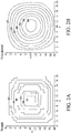
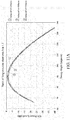
- FIG. 11A is the simulation result of a S21 power level scan (assuming 3D elliptic curve has 1 ⁇ 4 of an area, the ratio of the long axis a to the short axis b is 1.1, and the value of b is 250 mm, 500 mm, and 750 mm). As can be seen from the simulation result set forth in FIG. 11A , given that the ratios of the long axis a to the short axis b are unchanged, similar reflection characteristic can be obtained with different values of b.
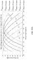
- FIG. 11B is the simulation result of a S21 power level scan (assuming 3D elliptic curve has 1 ⁇ 4 of an area, the ratio of the long axis a to the short axis b is 1.3, and the value of b is 250 mm, 500 mm, and 750 mm). As can be seen from the simulation result set forth in FIG. 11B , given that the ratios of the long axis a to the short axis b are unchanged, similar reflection characteristic can still be obtained with different values of b.
- FIGs. 11A and 11B indicate power levels received by the DUT at a fixed angle of 90 degrees at the first focal point F1 scanned by beams at different incident angles (i.e., different sweep angles) from the second focal point F2.
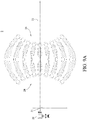
- FIG. 12A is the simulation result of a S21 power level scan (assuming 3D elliptic curve has 1 ⁇ 4 of an area, the ratio of the long axis a to the short axis b is 1.1, and the value of b is 250 mm).
- the angle of the power peak of the DUT is the transmitting angle at the originating focal point.
- FIG. 12B is the simulation result of a S21 power level scan (assuming 3D elliptic curve has 1 ⁇ 4 of an area, the ratio of the long axis a to the short axis b is 1.3, and the value of b is 250 mm).
- the angle of the power peak of the DUT is the transmitting angle at the originating focal point.
- FIGs. 12A and 12B indicate power levels received by the DUT at different beam angles (i.e., DUT sweep angles) at the first focal point F1 scanned by beams from the second focal point F2.
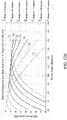
- FIG. 13 is the simulation result of a S21 power level scan (assuming 3D elliptic curve has 1 ⁇ 4 of an area and the value of b is 250 mm).
- different scan coverages resulted from different ratios (i.e., the ratio of long axis a to the short axis b); the larger the ratio, the lower the angle recognition rate; and on the other hand, the smaller the ratio, the higher the angle recognition rate.
- ratios 1.1 to 1.5 are used and a wider reflection range is obtained by increasing the curvature, then different application needs can be met.
- the present embodiment is able to realize rapid OTA testing through 3D elliptic curves or piecewise curves without the need for reflecting plates or complex mechanical components, thereby effectively reducing the cost of measurement.
- the various embodiments of the present disclosure described above includes the beamforming electronic probe for electronic scanning and reflective planes for DUT testing at different angles.
- electronic scanning is used by the present disclosure, it has significant improvements over the conventional mechanical scanning in terms of speed and precision.
- electronic probe is used in the present disclosure, there is the possibility for automated testing in overall OTA system integration.
Landscapes
- Physics & Mathematics (AREA)
- Electromagnetism (AREA)
- Engineering & Computer Science (AREA)
- General Physics & Mathematics (AREA)
- Signal Processing (AREA)
- Computer Networks & Wireless Communication (AREA)
- General Engineering & Computer Science (AREA)
- Variable-Direction Aerials And Aerial Arrays (AREA)
- Aerials With Secondary Devices (AREA)
- Production Of Multi-Layered Print Wiring Board (AREA)
- Structure Of Printed Boards (AREA)
- Microelectronics & Electronic Packaging (AREA)
- Support Of Aerials (AREA)
Applications Claiming Priority (1)
| Application Number | Priority Date | Filing Date | Title |
|---|---|---|---|
| US201962887815P | 2019-08-16 | 2019-08-16 |
Publications (4)
| Publication Number | Publication Date |
|---|---|
| EP3779477A2 true EP3779477A2 (de) | 2021-02-17 |
| EP3779477A3 EP3779477A3 (de) | 2021-05-26 |
| EP3779477B1 EP3779477B1 (de) | 2026-02-25 |
| EP3779477C0 EP3779477C0 (de) | 2026-02-25 |
Family
ID=72087893
Family Applications (3)
| Application Number | Title | Priority Date | Filing Date |
|---|---|---|---|
| EP20191138.5A Active EP3780275B1 (de) | 2019-08-16 | 2020-08-14 | Antenna in package-prüfplatte |
| EP20191023.9A Active EP3780259B1 (de) | 2019-08-16 | 2020-08-14 | Übergangsstruktur und mehrschichtige übergangsstruktur für millimeterwellen |
| EP20191147.6A Active EP3779477B1 (de) | 2019-08-16 | 2020-08-14 | Schnelle over-the-air-testplattform für produktionslinien |
Family Applications Before (2)
| Application Number | Title | Priority Date | Filing Date |
|---|---|---|---|
| EP20191138.5A Active EP3780275B1 (de) | 2019-08-16 | 2020-08-14 | Antenna in package-prüfplatte |
| EP20191023.9A Active EP3780259B1 (de) | 2019-08-16 | 2020-08-14 | Übergangsstruktur und mehrschichtige übergangsstruktur für millimeterwellen |
Country Status (5)
| Country | Link |
|---|---|
| US (4) | US11316240B2 (de) |
| EP (3) | EP3780275B1 (de) |
| JP (4) | JP7179803B2 (de) |
| CN (3) | CN112394233B (de) |
| TW (3) | TWI748579B (de) |
Cited By (1)
| Publication number | Priority date | Publication date | Assignee | Title |
|---|---|---|---|---|
| US11536760B2 (en) * | 2017-11-28 | 2022-12-27 | Ase Test, Inc. | Testing device, testing system, and testing method |
Families Citing this family (14)
| Publication number | Priority date | Publication date | Assignee | Title |
|---|---|---|---|---|
| CN112394233B (zh) * | 2019-08-16 | 2024-07-30 | 稜研科技股份有限公司 | 天线封装验证板 |
| EP4145149A1 (de) | 2021-09-07 | 2023-03-08 | TMY Technology Inc. | Breitbandmesssystem und messverfahren für breitbandeigenschaften |
| USD1057752S1 (en) * | 2021-10-08 | 2025-01-14 | Life Technologies Corporation | Display panel of an electroporation device with a graphical user interface |
| CN116112593B (zh) * | 2021-11-10 | 2026-01-02 | 深圳市计量质量检测研究院(国家高新技术计量站丶国家数字电子产品质量监督检验中心) | 用于ota测试的装夹装置 |
| TWI800098B (zh) | 2021-11-15 | 2023-04-21 | 貿聯國際股份有限公司 | 測試板 |
| EP4472573A4 (de) | 2022-02-03 | 2025-10-15 | James M Jackson | Systeme und verfahren für magnetische gelenke |
| USD1046883S1 (en) * | 2022-03-29 | 2024-10-15 | Tmy Technology Inc. | Display screen or portion thereof with graphical user interface |
| USD1044834S1 (en) * | 2022-03-29 | 2024-10-01 | Tmy Technology Inc. | Display screen or portion thereof with graphical user interface |
| USD1044833S1 (en) * | 2022-03-29 | 2024-10-01 | Tmy Technology Inc. | Display screen or portion thereof with graphical user interface |
| USD1046884S1 (en) * | 2022-04-25 | 2024-10-15 | Tmy Technology Inc. | Display screen or portion thereof with graphical user interface |
| USD1048052S1 (en) * | 2022-05-23 | 2024-10-22 | Tmy Technology Inc. | Display screen or portion thereof with graphical user interface |
| US12451611B2 (en) * | 2022-06-01 | 2025-10-21 | United States Of America As Represented By The Secretary Of The Air Force | 3D printed metallic dual-polarized vivaldi arrays on square and triangular lattices |
| TWI816468B (zh) * | 2022-07-14 | 2023-09-21 | 國立臺灣大學 | 陣列式射頻系統 |
| US12542351B2 (en) * | 2023-09-26 | 2026-02-03 | Silicon Laboratories Inc. | Automated AoX test system |
Family Cites Families (67)
| Publication number | Priority date | Publication date | Assignee | Title |
|---|---|---|---|---|
| JPS61239701A (ja) * | 1985-04-16 | 1986-10-25 | Mitsubishi Electric Corp | トリプレ−ト線路形t分岐 |
| JP2621703B2 (ja) * | 1991-09-06 | 1997-06-18 | 日本電気株式会社 | 複合給電形レーダ空中線 |
| RU2125275C1 (ru) * | 1997-05-06 | 1999-01-20 | Акционерное общество открытого типа Нижегородский авиастроительный завод "Сокол" | Устройство для имитации целей |
| JP2000216630A (ja) * | 1999-01-20 | 2000-08-04 | Alps Electric Co Ltd | アンテナ付き送受信器 |
| JP2001308547A (ja) * | 2000-04-27 | 2001-11-02 | Sharp Corp | 高周波多層回路基板 |
| JP4734723B2 (ja) | 2001-01-31 | 2011-07-27 | 凸版印刷株式会社 | 同軸ビアホールを用いた多層配線基板の製造方法 |
| US7024165B2 (en) * | 2001-06-14 | 2006-04-04 | Honeywell Federal Manufacturing & Technologies, Llc | ISM band to U-NII band frequency transverter and method of frequency transversion |
| DE10137838A1 (de) * | 2001-08-02 | 2003-02-13 | Philips Corp Intellectual Pty | GPS-Empfangsmodul |
| JP2003204209A (ja) * | 2002-01-07 | 2003-07-18 | Kyocera Corp | 高周波用配線基板 |
| JP2004108898A (ja) * | 2002-09-17 | 2004-04-08 | Advantest Corp | パフォーマンスボード及び試験システム |
| JP4545606B2 (ja) * | 2005-02-04 | 2010-09-15 | 三菱電機株式会社 | レーダ断面積測定装置 |
| US20060226928A1 (en) * | 2005-04-08 | 2006-10-12 | Henning Larry C | Ball coax interconnect |
| US7965986B2 (en) * | 2006-06-07 | 2011-06-21 | Ets-Lindgren, L.P. | Systems and methods for over-the-air testing of wireless systems |
| KR100926561B1 (ko) * | 2007-09-19 | 2009-11-12 | 한국전자통신연구원 | 유한 거리간 안테나 방사 패턴 측정 장치 및 방법 |
| CN101217322A (zh) * | 2008-01-16 | 2008-07-09 | 中兴通讯股份有限公司 | 无线usb调制解调器空中性能的测试系统和测试方法 |
| EP2371033A4 (de) * | 2008-12-12 | 2013-07-24 | Univ Nanyang Tech | Grid-array-antennen und integrationsstruktur |
| JP5474949B2 (ja) * | 2009-05-12 | 2014-04-16 | パナソニック株式会社 | アンテナ評価装置及びアンテナ評価方法 |
| WO2010139840A1 (en) * | 2009-06-03 | 2010-12-09 | Elektrobit System Test Oy | Over-the-air test |
| DE102009037336B4 (de) * | 2009-08-14 | 2024-10-31 | Rosenberger Hochfrequenztechnik Gmbh & Co. Kg | Antennencharakterisierung in einem Wellenleiter |
| CN102104200B (zh) * | 2010-10-28 | 2013-09-25 | 华南理工大学 | 曲线阵列馈源双焦抛物反射面空间功率合成天线 |
| US8360806B2 (en) * | 2010-12-22 | 2013-01-29 | Tyco Electronics Corporation | RF module |
| US9671445B2 (en) * | 2013-03-15 | 2017-06-06 | Litepoint Corporation | System and method for testing radio frequency wireless signal transceivers using wireless test signals |
| DE102013102714A1 (de) * | 2013-03-18 | 2014-09-18 | Schott Ag | Hochfrequenzdurchführung |
| CN103297161B (zh) | 2013-05-28 | 2016-03-02 | 惠州Tcl移动通信有限公司 | 一种终端天线接收灵敏度测试方法及系统 |
| US9154972B2 (en) * | 2013-06-12 | 2015-10-06 | Apple Inc. | Methods and apparatus for testing electronic devices with antenna arrays |
| JP6402962B2 (ja) * | 2013-07-17 | 2018-10-10 | パナソニックIpマネジメント株式会社 | 高周波モジュール |
| CN105580195B (zh) * | 2013-10-01 | 2019-07-16 | 索尼半导体解决方案公司 | 连接器装置和通信系统 |
| EP3095159A4 (de) * | 2014-01-17 | 2017-09-27 | Nuvotronics, Inc. | Testschnittstelleneinheit im wafer-masstab: vorrichtungen mit geringem verlust und hoher isolation und verfahren für hochdichte gemischte signalverbindungen und schütze |
| SG11201610578WA (en) * | 2014-06-20 | 2017-01-27 | Xcerra Corp | Test socket assembly and related methods |
| CN204243214U (zh) * | 2014-10-28 | 2015-04-01 | 中兴通讯股份有限公司 | 一种智能天线装置 |
| CN105634627B (zh) * | 2014-10-28 | 2021-04-02 | 中兴通讯股份有限公司 | 一种天线阵耦合校准网络装置及校准方法 |
| TWI540792B (zh) * | 2014-11-14 | 2016-07-01 | 亞東技術學院 | 天線系統的遠場調校系統 |
| US10297923B2 (en) * | 2014-12-12 | 2019-05-21 | The Boeing Company | Switchable transmit and receive phased array antenna |
| CA2913777A1 (en) * | 2014-12-15 | 2016-06-15 | University Of Windsor | Shielded rf transmission lines in low temperature co-fired ceramic constructs and method of making same |
| EP3182144B1 (de) * | 2015-04-10 | 2019-11-06 | General Test Systems Inc. | System zur prüfung eines drahtloses endgeräts und verfahren zur steuerung davon |
| CN106291145B (zh) * | 2015-05-12 | 2019-03-01 | 深圳市通用测试系统有限公司 | 无线终端的测试系统 |
| ES2843513T3 (es) * | 2015-12-16 | 2021-07-19 | Ranlos Ab | Método y aparato para probar comunicación inalámbrica con vehículos |
| CN106936524B (zh) * | 2015-12-31 | 2023-03-31 | 深圳市通用测试系统有限公司 | 无线终端的测试系统 |
| TWI594502B (zh) * | 2016-03-10 | 2017-08-01 | Nat Chung-Shan Inst Of Science And Tech | Millimeter wave antenna device and its millimeter wave antenna array device |
| CN109075839B (zh) * | 2016-04-26 | 2021-10-12 | 梁平 | 用于具有空中传输连接的大型mimo信道仿真器的空中传输信道状态信息获取 |
| DE102016111884B4 (de) * | 2016-06-29 | 2024-08-22 | Infineon Technologies Ag | Vorrichtung, System und Verfahren zum automatischen Testen integrierter Antennen |
| US11750303B2 (en) * | 2016-06-30 | 2023-09-05 | Keysight Technologies, Inc. | Compact system for characterizing a device under test (DUT) having integrated antenna array |
| US10085162B2 (en) * | 2016-07-22 | 2018-09-25 | Ets-Lindgren, Inc. | System and method for over-the-air testing of milli-meter wave and other beamforming technologies |
| CN106159404B (zh) * | 2016-09-29 | 2019-10-11 | 上海航天测控通信研究所 | 一种非均匀微带线至带状线过渡结构 |
| SE540655C2 (en) * | 2017-03-06 | 2018-10-09 | Bluetest Ab | Arrangement and method for measuring the performance of devices with wireless capability |
| CN108966264B (zh) * | 2017-05-22 | 2023-05-02 | 是德科技股份有限公司 | 对大规模多入多出无线系统执行空中测试的系统和方法 |
| MX2020000307A (es) * | 2017-07-10 | 2020-08-17 | Smart Medical Devices Inc | Dispositivos de comunicacion inalambrica esterilizables. |
| TWI635290B (zh) * | 2017-07-11 | 2018-09-11 | 川升股份有限公司 | 應用於多重路徑環境下的天線輻射場型量測系統 |
| IT201700086529A1 (it) * | 2017-07-27 | 2019-01-27 | Thales Alenia Space Italia Spa Con Unico Socio | Modulo d'antenna a microonde per applicazioni spaziali comprendente un modulo trasmetti/ricevi ibrido di tipo package su package |
| CN107834233B (zh) * | 2017-09-27 | 2019-04-02 | 中国电子科技集团公司第二十九研究所 | 一种垂直过渡结构 |
| WO2019079123A1 (en) * | 2017-10-17 | 2019-04-25 | Commscope Technologies Llc | VERTICAL TRANSITIONS FOR MICROWAVE AND MILLIMETER WAVE COMMUNICATION SYSTEMS HAVING MULTILAYER SUBSTRATES |
| US10462686B2 (en) * | 2017-10-23 | 2019-10-29 | Keysight Technologies, Inc. | Over the air (OTA) beamforming testing with a reduced number of receivers |
| KR102387939B1 (ko) * | 2017-11-28 | 2022-04-19 | 삼성전자주식회사 | 안테나 및 그 안테나를 포함하는 전자 장치 |
| US10809296B2 (en) * | 2017-11-28 | 2020-10-20 | Rohde & Schwarz Gmbh & Co. Kg | Over-the-air test system and method for testing a device under test |
| US10756828B2 (en) * | 2017-12-11 | 2020-08-25 | RF DSP Inc. | Millimeter wave RF channel emulator |
| US11662363B2 (en) * | 2017-12-29 | 2023-05-30 | Xcerra Corporation | Test socket assembly with antenna and related methods |
| US10916854B2 (en) * | 2018-03-29 | 2021-02-09 | Mediatek Inc. | Antenna structure with integrated coupling element and semiconductor package using the same |
| CN108598690B (zh) * | 2018-03-29 | 2024-02-20 | 广东通宇通讯股份有限公司 | 毫米波Massive MIMO天线单元及阵列天线 |
| CN109100639A (zh) * | 2018-09-13 | 2018-12-28 | 苏州永安丰新能源科技有限公司 | 一种用于通信设备环境适应性测试的ota测试装置及方法 |
| US10725080B2 (en) * | 2018-09-25 | 2020-07-28 | National Instruments Corporation | Correlation of device-under-test orientations and radio frequency measurements |
| TWM581775U (zh) * | 2018-11-23 | 2019-08-01 | 耀登科技股份有限公司 | High frequency antenna device |
| CN109889239B (zh) * | 2019-03-27 | 2020-12-08 | 北京邮电大学 | 一种用于mimo ota测试的双暗室结构及测试方法 |
| TWI720535B (zh) * | 2019-07-08 | 2021-03-01 | 中華精測科技股份有限公司 | 天線封裝積體電路測試裝置 |
| CN112394233B (zh) * | 2019-08-16 | 2024-07-30 | 稜研科技股份有限公司 | 天线封装验证板 |
| CN111416200B (zh) * | 2020-04-16 | 2025-01-28 | 中国电子科技集团公司第五十四研究所 | 圆极化封装天线 |
| US11695206B2 (en) * | 2020-06-01 | 2023-07-04 | United States Of America As Represented By The Secretary Of The Air Force | Monolithic decade-bandwidth ultra-wideband antenna array module |
| US12188970B2 (en) * | 2020-09-25 | 2025-01-07 | Tron Future Tech Inc. | Near-field testing apparatus for testing antenna array and related method |
-
2020
- 2020-07-24 CN CN202010723854.8A patent/CN112394233B/zh active Active
- 2020-07-24 TW TW109125128A patent/TWI748579B/zh active
- 2020-07-24 TW TW109125126A patent/TWI741695B/zh active
- 2020-07-24 CN CN202010725266.8A patent/CN112397863B/zh active Active
- 2020-08-12 CN CN202010806834.7A patent/CN112394234B/zh active Active
- 2020-08-12 TW TW109127363A patent/TWI751645B/zh active
- 2020-08-13 JP JP2020136687A patent/JP7179803B2/ja active Active
- 2020-08-13 JP JP2020136688A patent/JP7062219B2/ja active Active
- 2020-08-13 US US16/992,170 patent/US11316240B2/en active Active
- 2020-08-14 EP EP20191138.5A patent/EP3780275B1/de active Active
- 2020-08-14 US US16/993,351 patent/US11682818B2/en active Active
- 2020-08-14 US US16/993,348 patent/US11205827B2/en active Active
- 2020-08-14 EP EP20191023.9A patent/EP3780259B1/de active Active
- 2020-08-14 EP EP20191147.6A patent/EP3779477B1/de active Active
- 2020-08-14 JP JP2020136970A patent/JP7074811B2/ja active Active
-
2021
- 2021-10-13 US US17/500,928 patent/US11600894B2/en active Active
-
2022
- 2022-01-06 JP JP2022001172A patent/JP7329085B2/ja active Active
Cited By (1)
| Publication number | Priority date | Publication date | Assignee | Title |
|---|---|---|---|---|
| US11536760B2 (en) * | 2017-11-28 | 2022-12-27 | Ase Test, Inc. | Testing device, testing system, and testing method |
Also Published As
Similar Documents
| Publication | Publication Date | Title |
|---|---|---|
| US11600894B2 (en) | Rapid over-the-air production line test platform | |
| US11804913B2 (en) | Method, apparatus and system for measuring total radiated power of array antenna | |
| US10177862B2 (en) | System and method for performing over-the-air tests for massive multi-input/multi-output wireless system | |
| US10075249B2 (en) | Massive-MIMO antenna measurement device and method of measuring directivity thereof | |
| US8400366B2 (en) | Radiation efficiency measuring apparatus and radiation efficiency measuring method | |
| US8330661B2 (en) | System and method for measuring antenna radiation pattern in Fresnel region based on phi-variation method | |
| KR101360280B1 (ko) | 흡수재를 구비하지 않은 다중채널 근접장 측정 시스템 | |
| US11879926B2 (en) | Method, device, system and terminal for measuring total radiation power of array antenna and computer storage medium | |
| CN107390035B (zh) | 天线测量系统以及天线测量方法 | |
| CN110007157B (zh) | 天线测量系统以及天线测量方法 | |
| US11867738B2 (en) | Multipurpose millimeter-wave radio frequency system and methods of use | |
| CN211061611U (zh) | 一种车载雷达测试装置 | |
| JP6678554B2 (ja) | アンテナ測定装置 | |
| US11131701B1 (en) | Multi-probe anechoic chamber for beam performance testing of an active electronically steered array antenna | |
| CN115389825B (zh) | 一种有源阵列天线方向图的近场空口快速测量系统及方法 | |
| JP2008089567A (ja) | 放射効率測定装置 | |
| CN112034264A (zh) | 一种多探头紧缩场天线测试系统和生成方法 | |
| Zheng et al. | A study on the radiation characteristics of microelectronic probes | |
| Fordham | An introduction to antenna test ranges, measurements and instrumentation | |
| CN113917241A (zh) | 一种天线方向图快速测量和预估方法、系统、设备及终端 | |
| Kawamura et al. | Near-field measurement system for 5G massive MIMO base stations | |
| US20250355030A1 (en) | Antenna measurement method and system | |
| Lin et al. | Challenges and prospects of vehicle ota spherical near-field measurement probes | |
| EP4679735A1 (de) | Over-the-air-messsystem und -verfahren | |
| CN115524539B (zh) | 适用于小静区的封装天线相控数组辐射场型评估系统 |
Legal Events
| Date | Code | Title | Description |
|---|---|---|---|
| PUAI | Public reference made under article 153(3) epc to a published international application that has entered the european phase |
Free format text: ORIGINAL CODE: 0009012 |
|
| STAA | Information on the status of an ep patent application or granted ep patent |
Free format text: STATUS: REQUEST FOR EXAMINATION WAS MADE |
|
| 17P | Request for examination filed |
Effective date: 20200814 |
|
| AK | Designated contracting states |
Kind code of ref document: A2 Designated state(s): AL AT BE BG CH CY CZ DE DK EE ES FI FR GB GR HR HU IE IS IT LI LT LU LV MC MK MT NL NO PL PT RO RS SE SI SK SM TR |
|
| AX | Request for extension of the european patent |
Extension state: BA ME |
|
| PUAL | Search report despatched |
Free format text: ORIGINAL CODE: 0009013 |
|
| AK | Designated contracting states |
Kind code of ref document: A3 Designated state(s): AL AT BE BG CH CY CZ DE DK EE ES FI FR GB GR HR HU IE IS IT LI LT LU LV MC MK MT NL NO PL PT RO RS SE SI SK SM TR |
|
| RIC1 | Information provided on ipc code assigned before grant |
Ipc: G01R 29/10 20060101AFI20210420BHEP Ipc: G01R 31/302 20060101ALI20210420BHEP Ipc: G01R 29/08 20060101ALI20210420BHEP Ipc: H01Q 3/26 20060101ALI20210420BHEP Ipc: G01R 31/311 20060101ALN20210420BHEP |
|
| RIN1 | Information on inventor provided before grant (corrected) |
Inventor name: HSU, SHAO-CHUN Inventor name: LIN, YU-CHENG Inventor name: WU, JIUN-WEI Inventor name: HUANG, PO-CHIA Inventor name: FANG, CHIEN-TSE Inventor name: CHEN, WEI-YANG Inventor name: TAI, YANG Inventor name: KUO, SHUN-CHUNG Inventor name: TSAI, WEN-TSAI Inventor name: LIN, CHUEH-JEN Inventor name: CHANG, SU-WEI |
|
| STAA | Information on the status of an ep patent application or granted ep patent |
Free format text: STATUS: EXAMINATION IS IN PROGRESS |
|
| 17Q | First examination report despatched |
Effective date: 20230926 |
|
| GRAP | Despatch of communication of intention to grant a patent |
Free format text: ORIGINAL CODE: EPIDOSNIGR1 |
|
| STAA | Information on the status of an ep patent application or granted ep patent |
Free format text: STATUS: GRANT OF PATENT IS INTENDED |
|
| RIC1 | Information provided on ipc code assigned before grant |
Ipc: G01R 31/302 20060101ALN20250801BHEP Ipc: G01R 29/10 20060101AFI20250801BHEP Ipc: H01Q 15/06 20060101ALI20250801BHEP Ipc: H01Q 15/14 20060101ALI20250801BHEP Ipc: H01Q 19/06 20060101ALI20250801BHEP Ipc: H01Q 19/10 20060101ALI20250801BHEP Ipc: H01Q 3/26 20060101ALN20250801BHEP Ipc: G01R 29/08 20060101ALN20250801BHEP |
|
| INTG | Intention to grant announced |
Effective date: 20250822 |
|
| GRAS | Grant fee paid |
Free format text: ORIGINAL CODE: EPIDOSNIGR3 |
|
| RAP3 | Party data changed (applicant data changed or rights of an application transferred) |
Owner name: TMY TECHNOLOGY INC. |
|
| GRAA | (expected) grant |
Free format text: ORIGINAL CODE: 0009210 |
|
| STAA | Information on the status of an ep patent application or granted ep patent |
Free format text: STATUS: THE PATENT HAS BEEN GRANTED |
|
| AK | Designated contracting states |
Kind code of ref document: B1 Designated state(s): AL AT BE BG CH CY CZ DE DK EE ES FI FR GB GR HR HU IE IS IT LI LT LU LV MC MK MT NL NO PL PT RO RS SE SI SK SM TR |
|
| REG | Reference to a national code |
Ref country code: CH Ref legal event code: F10 Free format text: ST27 STATUS EVENT CODE: U-0-0-F10-F00 (AS PROVIDED BY THE NATIONAL OFFICE) Effective date: 20260225 Ref country code: GB Ref legal event code: FG4D |
|
| REG | Reference to a national code |
Ref country code: CH Ref legal event code: R17 Free format text: ST27 STATUS EVENT CODE: U-0-0-R10-R17 (AS PROVIDED BY THE NATIONAL OFFICE) Effective date: 20260302 |
|
| REG | Reference to a national code |
Ref country code: IE Ref legal event code: FG4D |