EP3778130A1 - Gehäuse für ein elektrohandwerkzeuggerät - Google Patents
Gehäuse für ein elektrohandwerkzeuggerät Download PDFInfo
- Publication number
- EP3778130A1 EP3778130A1 EP20188052.3A EP20188052A EP3778130A1 EP 3778130 A1 EP3778130 A1 EP 3778130A1 EP 20188052 A EP20188052 A EP 20188052A EP 3778130 A1 EP3778130 A1 EP 3778130A1
- Authority
- EP
- European Patent Office
- Prior art keywords
- housing
- outlet opening
- air outlet
- wall
- air
- Prior art date
- Legal status (The legal status is an assumption and is not a legal conclusion. Google has not performed a legal analysis and makes no representation as to the accuracy of the status listed.)
- Granted
Links
Images
Classifications
-
- B—PERFORMING OPERATIONS; TRANSPORTING
- B25—HAND TOOLS; PORTABLE POWER-DRIVEN TOOLS; MANIPULATORS
- B25F—COMBINATION OR MULTI-PURPOSE TOOLS NOT OTHERWISE PROVIDED FOR; DETAILS OR COMPONENTS OF PORTABLE POWER-DRIVEN TOOLS NOT PARTICULARLY RELATED TO THE OPERATIONS PERFORMED AND NOT OTHERWISE PROVIDED FOR
- B25F5/00—Details or components of portable power-driven tools not particularly related to the operations performed and not otherwise provided for
- B25F5/008—Cooling means
Definitions
- the invention relates to a housing for an electric hand tool device with at least one handle, with at least one air inlet opening and with at least one air outlet opening.
- the invention also relates to an electric hand tool device with such a housing.
- a generic housing is from the DE 11 2012 004 087 T5 known.
- the JP 2013-039652 A describes a power tool in which a grille is provided to prevent foreign objects from entering a ventilation hole.
- WO 2016/170119 A1 describes a handheld power tool with a housing which has an air inlet opening for drawing in cooling air and an air outlet opening via which cooling air can flow out of the housing.
- the JP 200006055 A describes a power tool with a housing having a plurality of air inlets and a plurality of air outlets.
- Another hand machine tool with air inlet and air outlet openings in the housing is from the DE 101 56 387 B4 known.
- these air outlet openings or the air exiting from them can be perceived as very annoying, for example if the air flows into the face of an operator. Often attempts are made to place the air outlet opening in an area that is not in the immediate vicinity of the face or other sensitive areas of the user when the device is in use. Due to the arrangement of the components within the housing of the electric hand tool device and the required flow of the same with the However, there are limits to cooling air. In addition, no openings can be arranged in certain areas of the housing, since dirt that occurs there when the device is used could penetrate into the interior of the housing. This applies, for example, when working overhead with a drill.
- the inventive in the flow direction of the air emerging from the air outlet opening at a distance from the same arranged wall results in a turbulence of the air, which prevents the creation of straight, disruptive air jets, so that there is less disturbance for the user and more options in With regard to the positioning of the air outlet opening.
- the wall acts as a kind of diffuser that swirls the air in such a way that it is discharged in different directions.
- Another advantage of the wall according to the invention is that any particles carried along with the air emerging from the air outlet opening hit the wall and are thereby slowed down and thus represent a lower risk for the user.
- a very good integration of the wall into the housing is achieved in that the wall is connected to the housing at two connection areas. On In this way, a high durability of the wall and the entire housing is achieved.
- the air outlet opening and the wall are arranged on the side of the housing opposite the handle. Any other disadvantages with regard to the positioning of the air outlet opening can also be avoided at this location.
- the wall is at a distance of 2 to 15 mm from the air outlet opening. Such a distance between the wall and the outlet opening has proven to be very advantageous with regard to generating a diffuse air flow.
- the size of the wall can be minimized. It is possible that some of the exiting air cannot hit the wall directly, but this is not relevant if the air outlet opening is located in an area that cannot cause disruption to the user.
- an electric hand tool device is specified with a housing according to the invention.
- Such an electric hand tool device can make particularly good use of the advantages mentioned above for the housing according to the invention, with a good flow through the housing and a good flow against the components of the electric hand tool device housed in the same.
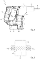
- FIG 1 shows a side view of an electric hand tool device 1, in the present case a drill or a hammer drill.
- the electric hand tool device 1 has a housing 2 in which the essential components of the electric hand tool device 1 are housed.
- a drive device 3 a gear 4 and control electronics 5 are arranged within the housing 2, each shown by means of dashed lines.
- the drive device 3, which can be designed as an electric motor, for example, is used to drive a tool 6, which is accommodated in a chuck 7 of the electric hand tool device 1.
- a battery 8, which can be connected to the housing 2 in a manner known per se, is used to supply power to the drive device 3 and the control electronics 5.
- a ventilation device 9 is arranged in the housing 2, which ventilation device 9 can be driven, for example, by the drive device 3 and which serves to generate an air flow within the housing 2.
- the ventilation device 9 can be designed as a fan wheel or have a fan wheel.
- the same has an air inlet opening 10 and an air outlet opening 11. While the air inlet opening 10 is provided in the present case on an underside of the housing 2, the air outlet opening 11 is located on a side of the housing 2 opposite a handle 12 of the housing 2 Control elements, such as an on and off switch, have.
- both the air inlet opening 10 and the air outlet opening 11 can be located in other positions of the housing 2.
- the position of the air inlet opening 10 and the air outlet opening 11 depend in particular on the positioning of the drive device 3 and the control electronics 5 within the housing 2, which are to be cooled by the air flow.
- the air exiting the air outlet opening 11 is arranged at a distance from the air outlet opening 11 having a wall 13.
- the wall 13 arranged in the housing 2 which can also be referred to as a baffle wall, is flown against by the air emerging from the air outlet opening 11 and distributes it, so that a sharp, directed air jet is prevented from exiting the air outlet opening 11. Instead, the result is a diffuse air flow which the user does not find disturbing.
- the wall 13 is at a distance of 2 to 15 mm, in particular 4 to 10 mm, from the air outlet opening 11.
- the exact distance between the wall 13 and the air outlet opening 11 depends, among other things, on the strength of the air flow emerging from the air outlet opening 11 and on the size of the electric hand tool device 1. For example, in the case of a stronger air flow and / or a larger electric hand tool device 1, the distance between the wall 13 and the air outlet opening 11 would tend to be greater than in the case of a weaker air flow or a smaller electric hand tool device 1.
- the wall 13 is connected to the housing 2 at two connection areas, namely an upper and a lower connection area.
- the wall 13 is preferably formed in one piece with the housing and is already taken into account in the injection mold, for example if the housing 2 is manufactured by means of injection molding.
- the air outlet opening 11 is provided on the side of the housing 2 opposite the handle 12.
- the wall 13 is also provided on the side of the housing 2 opposite the handle 12. This arrangement of the wall 13 prevents the air emerging from the air outlet opening 11 from flowing directly onto the hand of the user using the electric hand tool device 1 and from being able to disturb him. Since a hammer drill is often used at head height, the direct impact of the air flow on the face of the user can also be prevented in this way.
- the wall 13 can be arranged in front of the complete air outlet opening 11. In the present case, however, there is a partial area of the air outlet opening 11 free of the wall 13, ie the wall 13 is not located in front of a partial area of the air outlet opening 11.
- the wall 13 in the present case is arranged in front of a central partial area 11a of the air outlet opening 11 and that two lateral partial areas 11b of the air outlet opening 11 are free from the wall 13, that is, the wall 13 is not arranged in front of the lateral partial areas 11b .
- the air outlet opening 11 is formed from a multiplicity of individual openings. Nevertheless, an air outlet opening 11 is referred to herein.
- the individual openings in the lateral areas 11b of the air outlet opening 11 can, for example, have a smaller cross section than those in the central area 11a, so that the air flowing out of the lateral areas 11b is not regarded as disturbing.
Landscapes
- Engineering & Computer Science (AREA)
- Mechanical Engineering (AREA)
- Percussive Tools And Related Accessories (AREA)
- Drilling And Boring (AREA)
Abstract
Description
- Die Erfindung betrifft ein Gehäuse für ein Elektrohandwerkzeuggerät mit wenigstens einem Handgriff, mit wenigstens einer Lufteinlassöffnung und mit wenigstens einer Luftauslassöffnung. Des Weiteren betrifft die Erfindung ein Elektrohandwerkzeuggerät mit einem solchen Gehäuse.
- Ein gattungsgemäßes Gehäuse ist aus der
DE 11 2012 004 087 T5 bekannt. - Die
JP 2013-039652 A - In der
WO 2016/170119 A1 ist eine Handwerkzeugmaschine mit einem Gehäuse beschrieben, das eine Lufteinlassöffnung zum Ansaugen von Kühlluft und eine Luftauslassöffnung, über die Kühlluft aus dem Gehäuse abströmen kann, aufweist. - Die
JP 200006055 A - Eine weitere Handwerkzeugmaschine mit Lufteintritts- und Luftaustrittsöffnungen im Gehäuse ist aus der
DE 101 56 387 B4 bekannt. - Weitere ähnliche Elektrowerkzeuge sind in der
JP 2017-144523 A1 JP 2017-226025 A - Je nach Bauform des Geräts können diese Luftauslassöffnungen bzw. die aus denselben austretende Luft als sehr störend empfunden werden, beispielsweise wenn die Luft einer Bedienperson ins Gesicht strömt. Häufig wird versucht, die Luftauslassöffnung in einen Bereich zu legen, der sich bei der Benutzung des Geräts nicht unmittelbar in der Nähe des Gesichts oder anderer empfindlicher Stellen des Benutzers befindet. Aufgrund der Anordnung der Bauteile innerhalb des Gehäuses des Elektrohandwerkzeuggeräts und der erforderlichen Anströmung derselben mit der Kühlluft sind hier jedoch Grenzen gesetzt. Hinzu kommt, dass in bestimmten Bereichen des Gehäuses keine Öffnungen angeordnet werden können, da dort bei der Benutzung des Geräts entstehender Schmutz in das Innere des Gehäuses eindringen könnte. Dies gilt beispielsweise, wenn mit einer Bohrmaschine über Kopf gearbeitet wird.
- Des Weiteren kann es, beispielsweise wenn über die Lufteinlassöffnung Partikel eingesaugt werden, dazu kommen, dass diese durch die Luftauslassöffnung herausgeschleudert werden, was für einen Benutzer ebenfalls unangenehm sein kann.
- Es ist daher Aufgabe der vorliegenden Erfindung, ein Gehäuse für ein Elektrohandwerkzeuggerät sowie ein entsprechendes Elektrohandwerkzeuggerät zu schaffen, bei denen eine Störung für einen Benutzer durch aus einer Luftauslassöffnung des Gehäuses austretender Luft vermieden wird.
- Erfindungsgemäß wird diese Aufgabe durch die in Anspruch 1 genannten Merkmale gelöst.
- Durch die erfindungsgemäße, in Strömungsrichtung der aus der Luftauslassöffnung austretenden Luft mit einem Abstand von derselben angeordneten Wandung ergibt sich eine Verwirbelung der Luft, was die Entstehung von geradlinigen, störenden Luftstrahlen verhindert, so dass eine geringere Störung für den Benutzer gegeben ist und mehr Optionen im Hinblick auf die Positionierung der Luftauslassöffnung vorhanden sind. Die Wandung wirkt dabei als eine Art Diffusor, der die Luft so verwirbelt, dass diese in unterschiedliche Richtungen abgeführt wird.
- Ein weiterer Vorteil der erfindungsgemäßen Wandung besteht darin, dass eventuell mit der aus der Luftauslassöffnung austretenden Luft mitgeführte Partikel auf die Wandung treffen und dadurch abgebremst werden und somit eine geringere Gefahr für den Benutzer darstellen.
- Eine sehr gute Integration der Wandung in das Gehäuse wird dadurch erreicht, dass die Wandung an zwei Verbindungsbereichen mit dem Gehäuse verbunden ist. Auf diese Weise wird außerdem eine hohe Dauerhaltbarkeit der Wandung und des gesamten Gehäuses erreicht.
- Dadurch, dass die Wandung einteilig mit dem Gehäuse ausgebildet ist, ergibt sich eine besonders einfache Herstellung des Gehäuses.
- Im Hinblick auf eine gute Durchströmung des Gehäuses mit Kühlluft ist des Weiteren vorgesehen, dass die Luftauslassöffnung und die Wandung auf der dem Handgriff gegenüberliegenden Seite des Gehäuses angeordnet sind. An diesem Ort können außerdem eventuelle andere Nachteile hinsichtlich der Positionierung der Luftauslassöffnung vermieden werden.
- In einer sehr vorteilhaften Weiterbildung der Erfindung kann vorgesehen sein, dass die Wandung einen Abstand von 2 bis 15 mm von der Luftauslassöffnung aufweist. Ein solcher Abstand der Wandung von der Auslassöffnung hat sich im Hinblick auf das Erzeugen einer diffusen Luftströmung als sehr vorteilhaft erwiesen.
- Noch bessere Ergebnisse im Hinblick auf die Verwirbelung bzw. Umlenkung der Luft können erzielt werden, wenn die Wandung einen Abstand von 4 bis 10 mm von der Luftauslassöffnung aufweist.
- Wenn des Weiteren wenigstens ein Teilbereich der Luftauslassöffnung frei von der Wandung ist, so kann die Größe der Wandung minimiert werden. Dabei kann möglicherweise ein Teil der austretenden Luft nicht direkt auf die Wandung treffen, was jedoch dann nicht relevant ist, wenn sich die Luftauslassöffnung in einem Bereich befindet, der nicht zu einer Störung für den Benutzer führen kann.
- Dies gilt beispielsweise, wenn die Wandung vor einem mittleren Teilbereich der Luftauslassöffnung angeordnet ist und zwei seitliche Teilbereiche der Luftauslassöffnung frei von der Wandung sind.
- In Anspruch 6 ist ein Elektrohandwerkzeuggerät mit einem erfindungsgemäßen Gehäuse angegeben.
- Ein solches Elektrohandwerkzeuggerät kann die für das erfindungsgemäße Gehäuse oben genannten Vorteile besonders gut nutzen, wobei gleichzeitig eine gute Durchströmung des Gehäuses und eine gute Anströmung der in demselben untergebrachten Komponenten des Elektrohandwerkzeuggeräts gegeben sind.
- Diese Vorteile kommen insbesondere dann zum Tragen, wenn das Elektrohandwerkzeuggerät als Bohrmaschine, insbesondere als Bohrhammer, ausgebildet ist.
- Ergänzend sei darauf hingewiesen, dass Begriffe, wie "umfassend" "aufweisen" oder "mit" keine anderen Merkmale oder Schritte ausschließen. Ferner schließen Begriffe "ein" oder "das", die auf einer Einzahl von Schritten oder Merkmalen hinweisen, keine Mehrzahl von Merkmalen oder Schritten aus und umgekehrt.
- Weitere Merkmale und Vorteile der Erfindung ergeben sich aus der nachfolgenden Beschreibung eines Ausführungsbeispiels der Erfindung. Die Figuren zeigen mehrere Merkmale der Erfindung in Kombination miteinander. Selbstverständlich vermag der Fachmann diese jedoch auch losgelöst voneinander zu betrachten und gegebenenfalls zu weiteren sinnvollen Unterkombinationen zu kombinieren, ohne dass hierfür erfinderisch tätig werden zu müssen.
- Es zeigen schematisch:
- Figur 1
- eine Seitenansicht eines erfindungsgemäßen Elektrohandwerkzeuggeräts mit einem erfindungsgemäßen Gehäuse; und
- Figur 2
- eine sehr schematische Ansicht gemäß dem Pfeil II aus
Figur 1 . -
Figur 1 zeigt eine Seitenansicht eines Elektrohandwerkzeuggeräts 1, im vorliegenden Fall einer Bohrmaschine bzw. eines Bohrhammers. Das Elektrohandwerkzeuggerät 1 weist ein Gehäuse 2 auf, in dem die wesentlichen Komponenten des Elektrohandwerkzeuggeräts 1 untergebracht sind. Im vorliegenden Fall sind innerhalb des Gehäuses 2, jeweils mittels gestrichelter Linien dargestellt, eine Antriebseinrichtung 3, ein Getriebe 4 und eine Steuerungselektronik 5 angeordnet. Die Antriebseinrichtung 3, die beispielsweise als Elektromotor ausgebildet sein kann, dient zum Antrieb eines Werkzeugs 6, das in einem Spannfutter 7 des Elektrohandwerkzeuggeräts 1 aufgenommen ist. Zur Stromversorgung der Antriebseinrichtung 3 und der Steuerungselektronik 5 dient ein Akku 8, der in an sich bekannter Weise mit dem Gehäuse 2 verbunden sein kann. - In dem Gehäuse 2 ist des Weiteren eine Lüftungseinrichtung 9 angeordnet, die beispielsweise von der Antriebseinrichtung 3 angetrieben werden kann und die zur Erzeugung eines Luftstroms innerhalb des Gehäuses 2 dient. Beispielsweise kann die Lüftungseinrichtung 9 als Lüfterrad ausgebildet sein bzw. ein Lüfterrad aufweisen. Um den Luftstrom innerhalb des Gehäuses 2 zu ermöglichen, weist dasselbe eine Lufteinlassöffnung 10 und eine Luftauslassöffnung 11 auf. Während die Lufteinlassöffnung 10 im vorliegenden Fall an einer Unterseite des Gehäuses 2 vorgesehen ist, befindet sich die Luftauslassöffnung 11 auf einer einem Handgriff 12 des Gehäuses 2 gegenüberliegenden Seite des Gehäuses 2. Der Handgriff 12 dient zum Halten des Elektrohandwerkzeuggeräts 1 und kann hierzu nicht näher bezeichnete Bedienelemente, wie beispielsweise einen Ein- und Ausschalter, aufweisen.
- Selbstverständlich können sich sowohl die Lufteinlassöffnung 10 als auch die Luftauslassöffnung 11 an anderen Positionen des Gehäuses 2 befinden. Die Position der Lufteinlassöffnung 10 und der Luftauslassöffnung 11 hängen insbesondere von der Positionierung der Antriebseinrichtung 3 und der Steuerungselektronik 5 innerhalb des Gehäuses 2 ab, die durch den Luftstrom gekühlt werden sollen.
- Um zu verhindern, dass die aus der Luftauslassöffnung 11 austretende Luft eine Störung für einen Benutzer des Elektrohandwerkzeuggeräts 1 darstellt, ist in der mit "x" bezeichneten Strömungsrichtung der aus der Luftauslassöffnung 11 austretenden Luft nach zumindest einem Teilbereich der Luftauslassöffnung 11 eine zur Verwirbelung der aus der Luftauslassöffnung 11 austretenden Luft dienende, einen Abstand von der Luftauslassöffnung 11 aufweisende Wandung 13 angeordnet. Die außerhalb des Gehäuses 2 angeordnete Wandung 13, die auch als Prallwand bezeichnet werden kann, wird von der aus der Luftauslassöffnung 11 austretenden Luft angeströmt und verteilt diese, so dass das Austreten eines scharfen, gerichteten Luftstrahls aus der Luftauslassöffnung 11 verhindert wird. Stattdessen ergibt sich eine diffuse Luftströmung, die von dem Benutzer als nicht störend empfunden wird.
- Die Wandung 13 weist im vorliegenden Fall einen Abstand von 2 bis 15 mm, insbesondere 4 bis 10 mm, von der Luftauslassöffnung 11 auf. Der genaue Abstand der Wandung 13 von der Luftauslassöffnung 11 hängt unter anderem von der Stärke des aus der Luftauslassöffnung 11 austretenden Luftstroms und von der Größe des Elektrohandwerkzeuggeräts 1 ab. Beispielsweise wäre bei einem stärkeren Luftstrom und/oder einem größeren Elektrohandwerkzeuggerät 1 der Abstand der Wandung 13 von der Luftauslassöffnung 11 tendenziell größer als bei einem schwächeren Luftstrom bzw. einem kleineren Elektrohandwerkzeuggerät 1.
- Im dargestellten Ausführungsbeispiel ist die Wandung 13 an zwei Verbindungsbereichen, nämlich einem oberen und einem unteren Verbindungsbereich, mit dem Gehäuse 2 verbunden. Vorzugsweise ist die Wandung 13 einteilig mit dem Gehäuse ausgebildet und wird, beispielsweise wenn das Gehäuse 2 mittels Spritzgießen hergestellt wird, bereits in der Spritzgießform berücksichtigt.
- Wie bereits erwähnt, ist die Luftauslassöffnung 11 auf der dem Handgriff 12 gegenüberliegenden Seite des Gehäuses 2 vorgesehen. Selbstverständlich ist dadurch auch die Wandung 13 auf der dem Handgriff 12 gegenüberliegenden Seite des Gehäuses 2 vorgesehen. Durch diese Anordnung der Wandung 13 wird verhindert, dass die aus der Luftauslassöffnung 11 austretende Luft direkt auf die Hand des das Elektrohandwerkzeuggerät 1 verwendenden Benutzers strömen und diesen stören kann. Da ein Bohrhammer häufig in Kopfhöhe verwendet wird, kann auf diese Weise auch eine direkte Beaufschlagung des Gesichts des Benutzers durch die Luftströmung verhindert werden.
- Grundsätzlich kann die Wandung 13 vor der kompletten Luftauslassöffnung 11 angeordnet sein. Im vorliegenden Fall ist jedoch ein Teilbereich der Luftauslassöffnung 11 frei von der Wandung 13, d. h. vor einem Teilbereiche der Luftauslassöffnung 11 befindet sich die Wandung 13 nicht. In der sehr schematischen Darstellung von
Figur 2 ist erkennbar, dass die Wandung 13 im vorliegenden Fall vor einem mittleren Teilbereich 11a der Luftauslassöffnung 11 angeordnet ist und dass zwei seitliche Teilbereiche 11b der Luftauslassöffnung 11 frei von der Wandung 13 sind, d. h. dass die Wandung 13 vor den seitlichen Teilbereichen 11b gerade nicht angeordnet ist. In Figur 2 ist außerdem zu erkennen, dass die Luftauslassöffnung 11 aus einer Vielzahl einzelner Öffnungen gebildet ist. Dennoch wird hierin von einer Luftauslassöffnung 11 gesprochen. Die einzelnen Öffnungen in den seitlichen Bereichen 11b der Luftauslassöffnung 11 können beispielsweise einen kleineren Querschnitt aufweisen als diejenigen in dem mittleren Bereich 11a, sodass die aus den seitlichen Bereichen 11b ausströmende Luft als nicht störend angesehen wird.
Claims (7)
- Gehäuse (2) für ein Elektrohandwerkzeuggerät (1) mit wenigstens einem Handgriff (12), mit wenigstens einer Lufteinlassöffnung (10) und mit wenigstens einer Luftauslassöffnung (11), wobei in Strömungsrichtung (x) der aus der Luftauslassöffnung (11) austretenden Luft nach zumindest einem Teilbereich der Luftauslassöffnung (11) eine zur Verwirbelung der aus der Luftauslassöffnung (11) austretenden Luft dienende, einen Abstand von der Luftauslassöffnung (11) aufweisende Wandung (13) angeordnet ist,
dadurch gekennzeichnet, dass die Wandung (13) an zwei Verbindungsbereichen mit dem Gehäuse (2) verbunden ist, dass die Wandung (13) einteilig mit dem Gehäuse (2) ausgebildet ist, und dass die Luftauslassöffnung (11) und die Wandung (13) auf der dem Handgriff (12) gegenüberliegenden Seite des Gehäuses (2) angeordnet sind. - Gehäuse nach Anspruch 1,
dadurch gekennzeichnet, dass die Wandung (13) einen Abstand von 2 bis 15 mm von der Luftauslassöffnung (11) aufweist. - Gehäuse nach Anspruch 2,
dadurch gekennzeichnet, dass die Wandung (13) einen Abstand von 4 bis 10 mm von der Luftauslassöffnung (11) aufweist. - Gehäuse nach einem der Ansprüche 1 bis 3,
dadurch gekennzeichnet, dass wenigstens ein Teilbereich (11b) der Luftauslassöffnung (11) frei von der Wandung (13) ist. - Gehäuse nach Anspruch 4,
dadurch gekennzeichnet, dass die Wandung (13) vor einem mittleren Teilbereich (11a) der Luftauslassöffnung (11) angeordnet ist, und dass zwei seitliche Teilbereiche (11b) der Luftauslassöffnung (11) frei von der Wandung (13) sind. - Elektrohandwerkzeuggerät (1) mit einem Gehäuse (2) nach einem der Ansprüche 1 bis 5, mit einer in dem Gehäuse (2) angeordneten Antriebseinrichtung (3) zum Antrieb eines Werkzeugs (6) und mit einer in dem Gehäuse (2) angeordneten Lüftungseinrichtung (9) zur Erzeugung eines Luftstroms innerhalb des Gehäuses (2).
- Elektrohandwerkzeuggerät nach Anspruch 6,
dadurch gekennzeichnet, es als Bohrmaschine, insbesondere als Bohrhammer, ausgebildet ist.
Applications Claiming Priority (1)
| Application Number | Priority Date | Filing Date | Title |
|---|---|---|---|
| DE102019121699.0A DE102019121699B4 (de) | 2019-08-12 | 2019-08-12 | Gehäuse für ein Elektrohandwerkzeuggerät |
Publications (2)
| Publication Number | Publication Date |
|---|---|
| EP3778130A1 true EP3778130A1 (de) | 2021-02-17 |
| EP3778130B1 EP3778130B1 (de) | 2023-02-15 |
Family
ID=71842541
Family Applications (1)
| Application Number | Title | Priority Date | Filing Date |
|---|---|---|---|
| EP20188052.3A Active EP3778130B1 (de) | 2019-08-12 | 2020-07-28 | Gehäuse für ein elektrohandwerkzeuggerät |
Country Status (2)
| Country | Link |
|---|---|
| EP (1) | EP3778130B1 (de) |
| DE (1) | DE102019121699B4 (de) |
Cited By (1)
| Publication number | Priority date | Publication date | Assignee | Title |
|---|---|---|---|---|
| DE102021211950A1 (de) | 2021-10-22 | 2023-04-27 | Robert Bosch Gesellschaft mit beschränkter Haftung | Gehäusevorrichtung für eine Handwerkzeugmaschine und Handwerkzeugmaschine mit der Gehäusevorrichtung |
Citations (15)
| Publication number | Priority date | Publication date | Assignee | Title |
|---|---|---|---|---|
| JPS5849066A (ja) * | 1981-09-17 | 1983-03-23 | Toshiba Corp | 回転電機の通風ろか装置 |
| EP0794038A2 (de) * | 1996-01-08 | 1997-09-10 | Kress-elektrik GmbH + Co. Elektromotorenfabrik | Handwerkzeug mit Anordnung zum Kühlen |
| JP2000006055A (ja) | 1998-06-19 | 2000-01-11 | Hitachi Koki Co Ltd | 電動工具 |
| EP0984545A2 (de) * | 1998-09-02 | 2000-03-08 | HILTI Aktiengesellschaft | Elektrowerkzeug |
| DE19924552A1 (de) * | 1999-05-28 | 2000-11-30 | Hilti Ag | Elektrisch betreibbares Handgerät |
| DE10156387B4 (de) | 2001-11-16 | 2008-04-10 | Robert Bosch Gmbh | Handwerkzeugmaschine mit Lufteintritts- bzw. Luftaustrittsöffnungen im Gehäuse |
| DE102007039828B3 (de) * | 2007-08-23 | 2008-11-20 | Robert Bosch Gmbh | Elektrohandwerkzeugmaschine mit einem Lüfter und einem Akku |
| DE102008041370A1 (de) * | 2008-08-20 | 2010-02-25 | Robert Bosch Gmbh | Elektrowerkzeug |
| EP2366496A1 (de) * | 2010-03-19 | 2011-09-21 | Festool GmbH | Hand-Werkzeugmaschine mit einem Handgriff |
| EP2371493A1 (de) * | 2008-12-19 | 2011-10-05 | Makita Corporation | Arbeitswerkzeug |
| JP2013039652A (ja) | 2011-08-19 | 2013-02-28 | Hitachi Koki Co Ltd | 電動工具 |
| DE112012004087T5 (de) | 2011-09-30 | 2014-07-31 | Hitachi Koki Co., Ltd. | Leistungswerkzeug |
| WO2016170119A1 (de) | 2015-04-24 | 2016-10-27 | Hilti Aktiengesellschaft | Handwerkzeugmaschine |
| JP2017144523A (ja) | 2016-02-18 | 2017-08-24 | 株式会社マキタ | 回転工具 |
| JP2017226025A (ja) | 2016-06-20 | 2017-12-28 | 日立工機株式会社 | 電動工具 |
-
2019
- 2019-08-12 DE DE102019121699.0A patent/DE102019121699B4/de not_active Expired - Fee Related
-
2020
- 2020-07-28 EP EP20188052.3A patent/EP3778130B1/de active Active
Patent Citations (15)
| Publication number | Priority date | Publication date | Assignee | Title |
|---|---|---|---|---|
| JPS5849066A (ja) * | 1981-09-17 | 1983-03-23 | Toshiba Corp | 回転電機の通風ろか装置 |
| EP0794038A2 (de) * | 1996-01-08 | 1997-09-10 | Kress-elektrik GmbH + Co. Elektromotorenfabrik | Handwerkzeug mit Anordnung zum Kühlen |
| JP2000006055A (ja) | 1998-06-19 | 2000-01-11 | Hitachi Koki Co Ltd | 電動工具 |
| EP0984545A2 (de) * | 1998-09-02 | 2000-03-08 | HILTI Aktiengesellschaft | Elektrowerkzeug |
| DE19924552A1 (de) * | 1999-05-28 | 2000-11-30 | Hilti Ag | Elektrisch betreibbares Handgerät |
| DE10156387B4 (de) | 2001-11-16 | 2008-04-10 | Robert Bosch Gmbh | Handwerkzeugmaschine mit Lufteintritts- bzw. Luftaustrittsöffnungen im Gehäuse |
| DE102007039828B3 (de) * | 2007-08-23 | 2008-11-20 | Robert Bosch Gmbh | Elektrohandwerkzeugmaschine mit einem Lüfter und einem Akku |
| DE102008041370A1 (de) * | 2008-08-20 | 2010-02-25 | Robert Bosch Gmbh | Elektrowerkzeug |
| EP2371493A1 (de) * | 2008-12-19 | 2011-10-05 | Makita Corporation | Arbeitswerkzeug |
| EP2366496A1 (de) * | 2010-03-19 | 2011-09-21 | Festool GmbH | Hand-Werkzeugmaschine mit einem Handgriff |
| JP2013039652A (ja) | 2011-08-19 | 2013-02-28 | Hitachi Koki Co Ltd | 電動工具 |
| DE112012004087T5 (de) | 2011-09-30 | 2014-07-31 | Hitachi Koki Co., Ltd. | Leistungswerkzeug |
| WO2016170119A1 (de) | 2015-04-24 | 2016-10-27 | Hilti Aktiengesellschaft | Handwerkzeugmaschine |
| JP2017144523A (ja) | 2016-02-18 | 2017-08-24 | 株式会社マキタ | 回転工具 |
| JP2017226025A (ja) | 2016-06-20 | 2017-12-28 | 日立工機株式会社 | 電動工具 |
Cited By (1)
| Publication number | Priority date | Publication date | Assignee | Title |
|---|---|---|---|---|
| DE102021211950A1 (de) | 2021-10-22 | 2023-04-27 | Robert Bosch Gesellschaft mit beschränkter Haftung | Gehäusevorrichtung für eine Handwerkzeugmaschine und Handwerkzeugmaschine mit der Gehäusevorrichtung |
Also Published As
| Publication number | Publication date |
|---|---|
| EP3778130B1 (de) | 2023-02-15 |
| DE102019121699A1 (de) | 2021-02-18 |
| DE102019121699B4 (de) | 2023-02-16 |
Similar Documents
| Publication | Publication Date | Title |
|---|---|---|
| EP3679199B1 (de) | Strahlregler | |
| DE202014100752U1 (de) | Handgebläse | |
| DE112014006616B4 (de) | Lärmminderungssystem für einen Bläser | |
| EP0066289A2 (de) | Brausekopf | |
| DE102013004076B4 (de) | Strahlregler mit Prallfläche und Ringwandung | |
| DE10146000A1 (de) | Abzug | |
| DE102005001419B3 (de) | Strahlregler | |
| DE102015000732A1 (de) | Blasgerät | |
| EP3394354B1 (de) | Sanitäre auslaufeinheit | |
| WO2014067594A1 (de) | Strahlregler | |
| EP3327366B1 (de) | Luftauslass zum temperieren eines raumes | |
| EP3778130B1 (de) | Gehäuse für ein elektrohandwerkzeuggerät | |
| DE202011104072U1 (de) | Strahlregler | |
| EP1677947A1 (de) | Werkzeugmaschine und kühlmitteldurchtrittsanordnung | |
| DE202006003342U1 (de) | Strahlregler | |
| DE2138539A1 (de) | Verfahren und einrichtung zum einblasen von luft in einen raum | |
| EP2330958B1 (de) | Staubsauger | |
| DE1073716B (de) | Verfahren und Vorrichtung zum Em leiten von Luft in einen zu belüftenden Raum | |
| DE1146640B (de) | Vorrichtung zum Verteilen von aus einer Versorgungsleitung ausstroemender Luft | |
| DE202019101312U1 (de) | Strahlregler | |
| DE3303734C2 (de) | Oberfräse, insbesondere Elektrohandoberfräse | |
| DE19921404C1 (de) | Luftauslaß, insbesondere Luftauslaß für den Wandeinbau | |
| DE102006009828B3 (de) | Strahlregler | |
| EP0657014A1 (de) | Luftaustritt für belüftungsanlangen | |
| DE10313111B4 (de) | Brausekopf |
Legal Events
| Date | Code | Title | Description |
|---|---|---|---|
| PUAI | Public reference made under article 153(3) epc to a published international application that has entered the european phase |
Free format text: ORIGINAL CODE: 0009012 |
|
| STAA | Information on the status of an ep patent application or granted ep patent |
Free format text: STATUS: THE APPLICATION HAS BEEN PUBLISHED |
|
| AK | Designated contracting states |
Kind code of ref document: A1 Designated state(s): AL AT BE BG CH CY CZ DE DK EE ES FI FR GB GR HR HU IE IS IT LI LT LU LV MC MK MT NL NO PL PT RO RS SE SI SK SM TR |
|
| AX | Request for extension of the european patent |
Extension state: BA ME |
|
| STAA | Information on the status of an ep patent application or granted ep patent |
Free format text: STATUS: REQUEST FOR EXAMINATION WAS MADE |
|
| 17P | Request for examination filed |
Effective date: 20210319 |
|
| RBV | Designated contracting states (corrected) |
Designated state(s): AL AT BE BG CH CY CZ DE DK EE ES FI FR GB GR HR HU IE IS IT LI LT LU LV MC MK MT NL NO PL PT RO RS SE SI SK SM TR |
|
| GRAP | Despatch of communication of intention to grant a patent |
Free format text: ORIGINAL CODE: EPIDOSNIGR1 |
|
| STAA | Information on the status of an ep patent application or granted ep patent |
Free format text: STATUS: GRANT OF PATENT IS INTENDED |
|
| INTG | Intention to grant announced |
Effective date: 20221018 |
|
| GRAS | Grant fee paid |
Free format text: ORIGINAL CODE: EPIDOSNIGR3 |
|
| GRAA | (expected) grant |
Free format text: ORIGINAL CODE: 0009210 |
|
| STAA | Information on the status of an ep patent application or granted ep patent |
Free format text: STATUS: THE PATENT HAS BEEN GRANTED |
|
| AK | Designated contracting states |
Kind code of ref document: B1 Designated state(s): AL AT BE BG CH CY CZ DE DK EE ES FI FR GB GR HR HU IE IS IT LI LT LU LV MC MK MT NL NO PL PT RO RS SE SI SK SM TR |
|
| REG | Reference to a national code |
Ref country code: CH Ref legal event code: EP Ref country code: GB Ref legal event code: FG4D Free format text: NOT ENGLISH |
|
| REG | Reference to a national code |
Ref country code: DE Ref legal event code: R096 Ref document number: 502020002501 Country of ref document: DE |
|
| REG | Reference to a national code |
Ref country code: AT Ref legal event code: REF Ref document number: 1547997 Country of ref document: AT Kind code of ref document: T Effective date: 20230315 Ref country code: IE Ref legal event code: FG4D Free format text: LANGUAGE OF EP DOCUMENT: GERMAN |
|
| REG | Reference to a national code |
Ref country code: LT Ref legal event code: MG9D |
|
| REG | Reference to a national code |
Ref country code: NL Ref legal event code: MP Effective date: 20230215 |
|
| PG25 | Lapsed in a contracting state [announced via postgrant information from national office to epo] |
Ref country code: RS Free format text: LAPSE BECAUSE OF FAILURE TO SUBMIT A TRANSLATION OF THE DESCRIPTION OR TO PAY THE FEE WITHIN THE PRESCRIBED TIME-LIMIT Effective date: 20230215 Ref country code: PT Free format text: LAPSE BECAUSE OF FAILURE TO SUBMIT A TRANSLATION OF THE DESCRIPTION OR TO PAY THE FEE WITHIN THE PRESCRIBED TIME-LIMIT Effective date: 20230615 Ref country code: NO Free format text: LAPSE BECAUSE OF FAILURE TO SUBMIT A TRANSLATION OF THE DESCRIPTION OR TO PAY THE FEE WITHIN THE PRESCRIBED TIME-LIMIT Effective date: 20230515 Ref country code: NL Free format text: LAPSE BECAUSE OF FAILURE TO SUBMIT A TRANSLATION OF THE DESCRIPTION OR TO PAY THE FEE WITHIN THE PRESCRIBED TIME-LIMIT Effective date: 20230215 Ref country code: LV Free format text: LAPSE BECAUSE OF FAILURE TO SUBMIT A TRANSLATION OF THE DESCRIPTION OR TO PAY THE FEE WITHIN THE PRESCRIBED TIME-LIMIT Effective date: 20230215 Ref country code: LT Free format text: LAPSE BECAUSE OF FAILURE TO SUBMIT A TRANSLATION OF THE DESCRIPTION OR TO PAY THE FEE WITHIN THE PRESCRIBED TIME-LIMIT Effective date: 20230215 Ref country code: HR Free format text: LAPSE BECAUSE OF FAILURE TO SUBMIT A TRANSLATION OF THE DESCRIPTION OR TO PAY THE FEE WITHIN THE PRESCRIBED TIME-LIMIT Effective date: 20230215 Ref country code: ES Free format text: LAPSE BECAUSE OF FAILURE TO SUBMIT A TRANSLATION OF THE DESCRIPTION OR TO PAY THE FEE WITHIN THE PRESCRIBED TIME-LIMIT Effective date: 20230215 |
|
| PG25 | Lapsed in a contracting state [announced via postgrant information from national office to epo] |
Ref country code: SE Free format text: LAPSE BECAUSE OF FAILURE TO SUBMIT A TRANSLATION OF THE DESCRIPTION OR TO PAY THE FEE WITHIN THE PRESCRIBED TIME-LIMIT Effective date: 20230215 Ref country code: PL Free format text: LAPSE BECAUSE OF FAILURE TO SUBMIT A TRANSLATION OF THE DESCRIPTION OR TO PAY THE FEE WITHIN THE PRESCRIBED TIME-LIMIT Effective date: 20230215 Ref country code: IS Free format text: LAPSE BECAUSE OF FAILURE TO SUBMIT A TRANSLATION OF THE DESCRIPTION OR TO PAY THE FEE WITHIN THE PRESCRIBED TIME-LIMIT Effective date: 20230615 Ref country code: GR Free format text: LAPSE BECAUSE OF FAILURE TO SUBMIT A TRANSLATION OF THE DESCRIPTION OR TO PAY THE FEE WITHIN THE PRESCRIBED TIME-LIMIT Effective date: 20230516 Ref country code: FI Free format text: LAPSE BECAUSE OF FAILURE TO SUBMIT A TRANSLATION OF THE DESCRIPTION OR TO PAY THE FEE WITHIN THE PRESCRIBED TIME-LIMIT Effective date: 20230215 |
|
| PG25 | Lapsed in a contracting state [announced via postgrant information from national office to epo] |
Ref country code: SM Free format text: LAPSE BECAUSE OF FAILURE TO SUBMIT A TRANSLATION OF THE DESCRIPTION OR TO PAY THE FEE WITHIN THE PRESCRIBED TIME-LIMIT Effective date: 20230215 Ref country code: RO Free format text: LAPSE BECAUSE OF FAILURE TO SUBMIT A TRANSLATION OF THE DESCRIPTION OR TO PAY THE FEE WITHIN THE PRESCRIBED TIME-LIMIT Effective date: 20230215 Ref country code: EE Free format text: LAPSE BECAUSE OF FAILURE TO SUBMIT A TRANSLATION OF THE DESCRIPTION OR TO PAY THE FEE WITHIN THE PRESCRIBED TIME-LIMIT Effective date: 20230215 Ref country code: DK Free format text: LAPSE BECAUSE OF FAILURE TO SUBMIT A TRANSLATION OF THE DESCRIPTION OR TO PAY THE FEE WITHIN THE PRESCRIBED TIME-LIMIT Effective date: 20230215 Ref country code: CZ Free format text: LAPSE BECAUSE OF FAILURE TO SUBMIT A TRANSLATION OF THE DESCRIPTION OR TO PAY THE FEE WITHIN THE PRESCRIBED TIME-LIMIT Effective date: 20230215 |
|
| REG | Reference to a national code |
Ref country code: DE Ref legal event code: R097 Ref document number: 502020002501 Country of ref document: DE |
|
| PG25 | Lapsed in a contracting state [announced via postgrant information from national office to epo] |
Ref country code: SK Free format text: LAPSE BECAUSE OF FAILURE TO SUBMIT A TRANSLATION OF THE DESCRIPTION OR TO PAY THE FEE WITHIN THE PRESCRIBED TIME-LIMIT Effective date: 20230215 |
|
| PLBE | No opposition filed within time limit |
Free format text: ORIGINAL CODE: 0009261 |
|
| STAA | Information on the status of an ep patent application or granted ep patent |
Free format text: STATUS: NO OPPOSITION FILED WITHIN TIME LIMIT |
|
| 26N | No opposition filed |
Effective date: 20231116 |
|
| PG25 | Lapsed in a contracting state [announced via postgrant information from national office to epo] |
Ref country code: SI Free format text: LAPSE BECAUSE OF FAILURE TO SUBMIT A TRANSLATION OF THE DESCRIPTION OR TO PAY THE FEE WITHIN THE PRESCRIBED TIME-LIMIT Effective date: 20230215 |
|
| PG25 | Lapsed in a contracting state [announced via postgrant information from national office to epo] |
Ref country code: MC Free format text: LAPSE BECAUSE OF FAILURE TO SUBMIT A TRANSLATION OF THE DESCRIPTION OR TO PAY THE FEE WITHIN THE PRESCRIBED TIME-LIMIT Effective date: 20230215 |
|
| PG25 | Lapsed in a contracting state [announced via postgrant information from national office to epo] |
Ref country code: MC Free format text: LAPSE BECAUSE OF FAILURE TO SUBMIT A TRANSLATION OF THE DESCRIPTION OR TO PAY THE FEE WITHIN THE PRESCRIBED TIME-LIMIT Effective date: 20230215 |
|
| REG | Reference to a national code |
Ref country code: CH Ref legal event code: PL |
|
| REG | Reference to a national code |
Ref country code: BE Ref legal event code: MM Effective date: 20230731 |
|
| PG25 | Lapsed in a contracting state [announced via postgrant information from national office to epo] |
Ref country code: LU Free format text: LAPSE BECAUSE OF NON-PAYMENT OF DUE FEES Effective date: 20230728 |
|
| PG25 | Lapsed in a contracting state [announced via postgrant information from national office to epo] |
Ref country code: LU Free format text: LAPSE BECAUSE OF NON-PAYMENT OF DUE FEES Effective date: 20230728 |
|
| REG | Reference to a national code |
Ref country code: IE Ref legal event code: MM4A |
|
| PG25 | Lapsed in a contracting state [announced via postgrant information from national office to epo] |
Ref country code: CH Free format text: LAPSE BECAUSE OF NON-PAYMENT OF DUE FEES Effective date: 20230731 |
|
| PG25 | Lapsed in a contracting state [announced via postgrant information from national office to epo] |
Ref country code: IT Free format text: LAPSE BECAUSE OF FAILURE TO SUBMIT A TRANSLATION OF THE DESCRIPTION OR TO PAY THE FEE WITHIN THE PRESCRIBED TIME-LIMIT Effective date: 20230215 Ref country code: BE Free format text: LAPSE BECAUSE OF NON-PAYMENT OF DUE FEES Effective date: 20230731 |
|
| PG25 | Lapsed in a contracting state [announced via postgrant information from national office to epo] |
Ref country code: IE Free format text: LAPSE BECAUSE OF NON-PAYMENT OF DUE FEES Effective date: 20230728 |
|
| PG25 | Lapsed in a contracting state [announced via postgrant information from national office to epo] |
Ref country code: IE Free format text: LAPSE BECAUSE OF NON-PAYMENT OF DUE FEES Effective date: 20230728 |
|
| PG25 | Lapsed in a contracting state [announced via postgrant information from national office to epo] |
Ref country code: BG Free format text: LAPSE BECAUSE OF FAILURE TO SUBMIT A TRANSLATION OF THE DESCRIPTION OR TO PAY THE FEE WITHIN THE PRESCRIBED TIME-LIMIT Effective date: 20230215 |
|
| PG25 | Lapsed in a contracting state [announced via postgrant information from national office to epo] |
Ref country code: BG Free format text: LAPSE BECAUSE OF FAILURE TO SUBMIT A TRANSLATION OF THE DESCRIPTION OR TO PAY THE FEE WITHIN THE PRESCRIBED TIME-LIMIT Effective date: 20230215 |
|
| GBPC | Gb: european patent ceased through non-payment of renewal fee |
Effective date: 20240728 |
|
| PG25 | Lapsed in a contracting state [announced via postgrant information from national office to epo] |
Ref country code: GB Free format text: LAPSE BECAUSE OF NON-PAYMENT OF DUE FEES Effective date: 20240728 |
|
| PG25 | Lapsed in a contracting state [announced via postgrant information from national office to epo] |
Ref country code: CY Free format text: LAPSE BECAUSE OF FAILURE TO SUBMIT A TRANSLATION OF THE DESCRIPTION OR TO PAY THE FEE WITHIN THE PRESCRIBED TIME-LIMIT; INVALID AB INITIO Effective date: 20200728 |
|
| PG25 | Lapsed in a contracting state [announced via postgrant information from national office to epo] |
Ref country code: HU Free format text: LAPSE BECAUSE OF FAILURE TO SUBMIT A TRANSLATION OF THE DESCRIPTION OR TO PAY THE FEE WITHIN THE PRESCRIBED TIME-LIMIT; INVALID AB INITIO Effective date: 20200728 |
|
| PGFP | Annual fee paid to national office [announced via postgrant information from national office to epo] |
Ref country code: DE Payment date: 20250722 Year of fee payment: 6 |
|
| PGFP | Annual fee paid to national office [announced via postgrant information from national office to epo] |
Ref country code: FR Payment date: 20250723 Year of fee payment: 6 Ref country code: AT Payment date: 20251020 Year of fee payment: 5 |
|
| PG25 | Lapsed in a contracting state [announced via postgrant information from national office to epo] |
Ref country code: TR Free format text: LAPSE BECAUSE OF FAILURE TO SUBMIT A TRANSLATION OF THE DESCRIPTION OR TO PAY THE FEE WITHIN THE PRESCRIBED TIME-LIMIT Effective date: 20230215 |