EP3771504B1 - Pressvorrichtung - Google Patents
Pressvorrichtung Download PDFInfo
- Publication number
- EP3771504B1 EP3771504B1 EP20179905.3A EP20179905A EP3771504B1 EP 3771504 B1 EP3771504 B1 EP 3771504B1 EP 20179905 A EP20179905 A EP 20179905A EP 3771504 B1 EP3771504 B1 EP 3771504B1
- Authority
- EP
- European Patent Office
- Prior art keywords
- punch
- knockout pin
- workpiece
- die
- rod
- Prior art date
- Legal status (The legal status is an assumption and is not a legal conclusion. Google has not performed a legal analysis and makes no representation as to the accuracy of the status listed.)
- Active
Links
Images







Classifications
-
- B—PERFORMING OPERATIONS; TRANSPORTING
- B21—MECHANICAL METAL-WORKING WITHOUT ESSENTIALLY REMOVING MATERIAL; PUNCHING METAL
- B21D—WORKING OR PROCESSING OF SHEET METAL OR METAL TUBES, RODS OR PROFILES WITHOUT ESSENTIALLY REMOVING MATERIAL; PUNCHING METAL
- B21D28/00—Shaping by press-cutting; Perforating
- B21D28/24—Perforating, i.e. punching holes
- B21D28/34—Perforating tools; Die holders
-
- B—PERFORMING OPERATIONS; TRANSPORTING
- B21—MECHANICAL METAL-WORKING WITHOUT ESSENTIALLY REMOVING MATERIAL; PUNCHING METAL
- B21D—WORKING OR PROCESSING OF SHEET METAL OR METAL TUBES, RODS OR PROFILES WITHOUT ESSENTIALLY REMOVING MATERIAL; PUNCHING METAL
- B21D28/00—Shaping by press-cutting; Perforating
- B21D28/02—Punching blanks or articles with or without obtaining scrap; Notching
-
- B—PERFORMING OPERATIONS; TRANSPORTING
- B21—MECHANICAL METAL-WORKING WITHOUT ESSENTIALLY REMOVING MATERIAL; PUNCHING METAL
- B21D—WORKING OR PROCESSING OF SHEET METAL OR METAL TUBES, RODS OR PROFILES WITHOUT ESSENTIALLY REMOVING MATERIAL; PUNCHING METAL
- B21D22/00—Shaping without cutting, by stamping, spinning, or deep-drawing
- B21D22/20—Deep-drawing
- B21D22/21—Deep-drawing without fixing the border of the blank
-
- B—PERFORMING OPERATIONS; TRANSPORTING
- B21—MECHANICAL METAL-WORKING WITHOUT ESSENTIALLY REMOVING MATERIAL; PUNCHING METAL
- B21D—WORKING OR PROCESSING OF SHEET METAL OR METAL TUBES, RODS OR PROFILES WITHOUT ESSENTIALLY REMOVING MATERIAL; PUNCHING METAL
- B21D28/00—Shaping by press-cutting; Perforating
- B21D28/02—Punching blanks or articles with or without obtaining scrap; Notching
- B21D28/14—Dies
-
- B—PERFORMING OPERATIONS; TRANSPORTING
- B21—MECHANICAL METAL-WORKING WITHOUT ESSENTIALLY REMOVING MATERIAL; PUNCHING METAL
- B21D—WORKING OR PROCESSING OF SHEET METAL OR METAL TUBES, RODS OR PROFILES WITHOUT ESSENTIALLY REMOVING MATERIAL; PUNCHING METAL
- B21D28/00—Shaping by press-cutting; Perforating
- B21D28/02—Punching blanks or articles with or without obtaining scrap; Notching
- B21D28/14—Dies
- B21D28/145—Dies with means for slug retention, e.g. a groove
-
- B—PERFORMING OPERATIONS; TRANSPORTING
- B21—MECHANICAL METAL-WORKING WITHOUT ESSENTIALLY REMOVING MATERIAL; PUNCHING METAL
- B21D—WORKING OR PROCESSING OF SHEET METAL OR METAL TUBES, RODS OR PROFILES WITHOUT ESSENTIALLY REMOVING MATERIAL; PUNCHING METAL
- B21D43/00—Feeding, positioning or storing devices combined with, or arranged in, or specially adapted for use in connection with, apparatus for working or processing sheet metal, metal tubes or metal profiles; Associations therewith of cutting devices
- B21D43/02—Advancing work in relation to the stroke of the die or tool
- B21D43/04—Advancing work in relation to the stroke of the die or tool by means in mechanical engagement with the work
- B21D43/05—Advancing work in relation to the stroke of the die or tool by means in mechanical engagement with the work specially adapted for multi-stage presses
- B21D43/055—Devices comprising a pair of longitudinally and laterally movable parallel transfer bars
-
- B—PERFORMING OPERATIONS; TRANSPORTING
- B21—MECHANICAL METAL-WORKING WITHOUT ESSENTIALLY REMOVING MATERIAL; PUNCHING METAL
- B21D—WORKING OR PROCESSING OF SHEET METAL OR METAL TUBES, RODS OR PROFILES WITHOUT ESSENTIALLY REMOVING MATERIAL; PUNCHING METAL
- B21D45/00—Ejecting or stripping-off devices arranged in machines or tools dealt with in this subclass
- B21D45/02—Ejecting devices
-
- B—PERFORMING OPERATIONS; TRANSPORTING
- B21—MECHANICAL METAL-WORKING WITHOUT ESSENTIALLY REMOVING MATERIAL; PUNCHING METAL
- B21D—WORKING OR PROCESSING OF SHEET METAL OR METAL TUBES, RODS OR PROFILES WITHOUT ESSENTIALLY REMOVING MATERIAL; PUNCHING METAL
- B21D45/00—Ejecting or stripping-off devices arranged in machines or tools dealt with in this subclass
- B21D45/02—Ejecting devices
- B21D45/04—Ejecting devices interrelated with motion of tool
Definitions
- the present disclosure relates to a press apparatus in which punches, dies, and knockout pins cooperate in processing a workpiece.
- a conventionally known press apparatus carries out punch work by placing a sheet metal on the upper surface of a die and pushing a part of the sheet metal as a workpiece into a through hole of the die by a first punch to punch out the workpiece from the sheet metal.
- a second punch extends downward from inside the first punch and holds the workpiece between the second punch and the knockout pin, to carry the workpiece to a discharge position (for example, see JP 2016-203212 A (paragraph [0030], Fig. 13 )).
- Other conventional known press apparatus carries out drawing or ironing by disposing a cylindrical workpiece on the upper surface of a die and pushing the workpiece into a through hole of the die by a punch.
- the punch further shifts downward, to carry the workpiece to workpiece discharge space beneath the die (for example, see JP 11-090547 A (paragraph [0038], Fig. 4 )).
- the workpiece may deform as being bulging away from the punch.
- the knockout pin is pushing the workpiece toward the punch.
- JP 2018-65187 A discloses a press machine including a punch according to the preamble of claim 1.
- the pushing force of the knockout pin toward the workpiece gradually increases as the knockout pin shifts downward with the punch and the workpiece. Accordingly, the punch must have a strength enough to withstand the pushing force of the knockout pin, which limits flexibility in designing the punch.
- a press apparatus that allows more flexible design for a punch than the conventional technique.
- a first aspect of the invention to solve the problem is a press apparatus according to claim 1.
- the transfer press machine 10 includes a plurality of punches 15 which are horizontally aligned at a certain interval at a lower end of a ram 14.
- the alignment direction of the plurality of punches 15 is referred to as "the lateral direction H1”
- the horizontal direction perpendicular to the lateral direction H1 is referred to as "the front-rear direction H2”.
- the right and left sides in Fig. 1 are simply referred to as "the right side and the left side”.
- a frame 11 of the transfer press machine 10 includes: a pair of side walls 11A, 11B standing vertically from a mount part 11D and opposing to each other in the lateral direction H1; and a ram supporting wall (not shown), a bolster supporting wall 12 and others extending between the side walls 11A, 11B.
- the ram supporting wall vertically shiftably supports the ram 14 via a not-shown slide guide.
- a camshaft 17 extends at a level higher than the ram supporting wall.
- the ram 14 engages with cams (not shown) of the camshaft 17.
- One end of the camshaft 17 projects laterally than the right side wall 11B.
- an inverter motor (not shown) is coupled via a large gear 18 and not-shown plurality of transmission components (a pulley, a timing belt, gears and the like) .
- the inverter motor rotates the camshaft 17, whereby the ram 14 reciprocates vertically.
- the bolster supporting wall 12 extends between the lower ends of the pair of side walls 11A, 11B.
- a bolster 16 is fixed to the upper surface of the bolster supporting wall 12.
- a plurality of die holders 13H are fixed to the upper surface of the bolster 16. Recessed parts formed at the upper surfaces of the die holders 13H receive and fix a plurality of dies 13 corresponding to the plurality of punches 15.
- the plurality of punches 15 and dies 13 vertically opposing to each other are paired to form a plurality of process stages ST.
- a composite punch 50 is provided on the left side of the plurality of punches 15.
- the interval between the composite punch 50 and the leftmost punch 15 is identical to the interval of the punches 15.
- a die holder 48 being greater in the vertical direction than the die holders 13H is provided.
- a die 60 corresponding to the composite punch 50 is fixed.
- the portion relating to the composite punch 50 and the die 60 is the workpiece feeding apparatus 45 which corresponds to "a press apparatus" in the scope of claims.
- a disc-like workpiece 90 is punched out from a sheet metal 89.
- the workpiece feeding apparatus 45 will be detailed later.
- the transfer apparatus 91 includes a pair of rails 92 (see Fig. 3 , Fig. 2 shows just part of the rails 92) which extends in the lateral direction H1 over the upper surfaces of the plurality of die holders 13H.
- the rails 92 oppose to each other in the front-rear direction H2.
- the pair of rails 92 is provided with a plurality of pairs of fingers 94 shown in Fig. 3 .
- the plurality of pairs of fingers 94 are arranged at the interval identical to that of the punches 15 in the longitudinal direction of the rails 92.
- the pairs of fingers 94 are supported so as to be slidable in the front-rear direction H2, and biased in a direction approaching each other by a compression coil spring 95. Each of the pairs of fingers 94 opens and closes as the corresponding punch 15 or knockout pin 53 advances between or retracts from between the pair.
- the transfer apparatus 91 operates by the motive power received from the camshaft 17.
- the pair of rails 92 In synchronization with the up-and-down operation of the ram 14, the pair of rails 92 repeatedly reciprocates in the lateral direction H1.
- the workpieces 90 are successively transferred to be processed from the workpiece feeding apparatus 45 to the next right-side process stage ST, and to the further right-side process stages ST.
- a vertical shaft 40 is provided on the left side of the frame 11.
- the vertical shaft 40 extends from the position near the upper end of the frame 11 to the position near the lower end thereof, and is rotatably supported by a supporting projection 11T which projects laterally from the side wall 11A of the frame 11.
- the upper end of the vertical shaft 40 is coupled to one end of the camshaft 17 penetrating through the side wall 11A via bevel gears 40G.
- a not-shown cam is provided so as to be integrally rotatable.
- the cam is disposed between a not-shown pair of beam parts disposed across the pair of rails 92.
- a camshaft 42 is disposed across the lower ends of the side walls 11A, 11B of the frame 11. One end of the camshaft 42 penetrates through the side wall 11A of the frame 11, and coupled to the lower end of the vertical shaft 40 via not-shown bevel gears.
- a not-shown plurality of cams are integrally rotatably fixed to the camshaft 42 at the position immediately below the process stages ST.
- Knockout pins 43 provided at the stages ST are in sliding contact with the cams to reciprocate in the vertical direction.
- the workpiece 90 punched out from the sheet metal 89 in the workpiece feeding apparatus 45 is shaped to be cylindrical at the first process stage ST (the leftmost process stage ST), and gradually cylindrically elongated as it passes through downstream process stages ST. From the downstream terminal process stage ST to the next not-shown chute, the workpiece 90 is discharged by the transfer apparatus 91.
- the die holder 48 of the workpiece feeding apparatus 45 is higher than the die holders 13H of the process stages ST.
- the die holder 48 is provided with a lateral hole 48A that penetrates in the lateral direction H1.
- the inner lower surface of the lateral hole 48A is flush with the upper surfaces of the die holders 13H of the process stages ST.
- the cross-sectional shape of the lateral hole 48A is rectangular elongated in the front-rear direction H2 than the vertical direction.
- the above-described pair of rails 92 passes through in the lateral direction H1 at the both ends of the lateral hole 48A in the front-rear direction H2.
- the workpiece 90 having been punched out from the sheet metal 89 by the workpiece feeding apparatus 45 is transferred to the process stages ST while held between the pair of fingers 94.
- the opposing surfaces of the leftmost pair of fingers 94 in the plurality of pairs of fingers 94 are each provided with an engaging groove 94A for engaging with the edge of the disc-like workpiece 90. Note that, in the present embodiment, the position where the workpiece 90 is held between the pair of fingers 94 corresponds to "a discharge position" in the scope of claims.
- a sheet metal cover 49 is fixed to the upper surface of the die holder 48.
- the sheet metal cover 49 has a pair of leg parts at the both ends in the lateral direction H1.
- the sheet metal cover 49 is fixed so as to cross over the die 60 and to oppose to the die 60 from above with a gap.
- a through hole 49A is formed coaxially to the through hole 61 of the die 60. Via the through hole 49A, the composite punch 50 enters the through hole 61 of the die 60.
- a not-shown sheet metal feeding apparatus disposed on the front or rear side of the die holder 48 holds the sheet metal 89 and keeps the sheet metal 89 abutted on the upper surface of the die 60, and shifts the sheet metal 89 in synchronization with the up-and-down operation of the ram 14.
- a through hole 65 is formed coaxially to the through hole 61 of the die 60.
- component housing space 12A is provided, to penetrate vertically through the bolster supporting wall 12 and communicate with the through hole 65.
- the knockout pin 53 corresponding to the composite punch 50 extends across the lower end of the bolster supporting wall 12 to the die holder 48.
- the knockout pin 53 includes a separate part 53L at the position near the upper end. Depending on the shape of the composite punch 50 and the die 60, a pin body part 53H on the separate part 53L is replaced. In the knockout pin 53, a pin body supporting part 53J below the separate part 53L is greater in diameter than the pin body part 53H. Correspondingly, the above-described through hole 65 has its diameter widened stepwise at the portion lower than the position near the lower end of the die holder 48. As shown in Fig. 3 , at the position near the upper end in the pin body part 53H, a tapered part 53T having its diameter reduced upward is provided. A tip smaller-diameter part 53A on the tapered part 53T is configured to loosely fit into the through hole 65 of the die 60 from below. The structure of the pin body supporting part 53J of the knockout pin 53 will be described later.
- the composite punch 50 is made up of a cylindrical first punch 51 and a second punch 52 fitted into the first punch 51.
- the first punch 51 is fixed to the ram 14 (see Fig. 1 ) .
- the second punch 52 is supported so as to be vertically shiftable relative to the first punch 51.
- one end of a seesaw-type lever 54 is coupled to the upper end of the second punch 52.
- the intermediate part in the longitudinal direction of the lever 54 is rotatably supported by, for example, the side wall 11A of the frame 11.
- the other end of the lever 54 engages with a cam groove 55A of a roll part 55 that integrally rotates with the vertical shaft 40.
- the first punch 51 and the second punch 52 shifts upward and downward in synchronization.
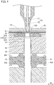
- the composite punch 50 and the knockout pin 53 cooperate with each other to punch out the workpiece 90 from the sheet metal 89 as follows. That is, the composite punch 50 shifts downward toward the sheet metal 89. Before reaching the sheet metal 89, the knockout pin 53 has its upper end surface positioned at an origin position where the upper end surface becomes flush with the upper surface of the die 60. The composite punch 50 has the lower end of the second punch 52 housed in the first punch 51. Then, as shown in Fig. 4 , the composite punch 50 reaches the sheet metal 89, and the first punch 51 presses part of the sheet metal 89 to push it into the through hole 61 of the die 60.
- the knockout pin 53 biased toward the origin position by first and second compression coil springs 73, 83, which will be described later, prevents the sheet metal 89 from deforming and bulging downward. Then, the first punch 51 punches out the part of the sheet metal 89 as the workpiece 90.
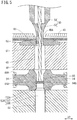
- the second punch 52 begins to extend downward from the first punch 51.
- the workpiece 90 held between the second punch 52 and the knockout pin 53 is pushed downward to the engaging grooves 94A of the pair of fingers 94 (that is, to the discharge position).
- the workpiece 90 shifts downward to reach the engaging grooves 94A while avoiding contact with the opposing surfaces of the pair of fingers 94.
- the greater-diameter part 53B of the pin body part 53H of the knockout pin 53 just passes through the pair of fingers 94 downward, and the edge of the workpiece 90 engages with the engaging grooves 94A.
- the knockout pin 53 shifts further downward to become spaced apart from the workpiece 90, and the second punch 52 shifts upward to become spaced apart from the workpiece 90.
- the first punch 51 has already started shifting upward at this time point
- the second punch 52 shifts upward faster than the first punch 51 and, accordingly, is housed in the first punch 51.
- the pair of rails 92 slides to discharge the workpiece 90 from the workpiece feeding apparatus 45 to the next process stage ST.
- the pair of rails 92 slides to return to the original position.
- a first projection part 56A, a second projection part 56B, and a third projection part 56C from the top in order are respectively provided, and project stepwise laterally.
- a lower supporting base 111 is fixed to the lower surface of the bolster supporting wall 12.
- a portion between the second and third projection parts 56B, 56C in the knockout pin 53 penetrates through a through hole 111A formed at the lower supporting base 111, so as to be linearly shiftable.
- a plurality of supporting legs 112 extend upward from the lower supporting base 111.
- the supporting legs 112 are supported by an upper supporting base 113.
- a groove part 113A penetrating in the vertical direction and opened laterally is formed at the upper supporting base 113. Through the groove part 113A, the portion between the first and second projection parts 56A, 56B in the knockout pin 53 penetrates vertically.
- the second compression coil spring 83 is provided at the upper portion than the upper supporting base 113 in the knockout pin 53, and stretches between the first projection part 56A and the upper supporting base 113, thereby to bias the knockout pin 53 upward.
- a cylinder 114 In the position coaxially immediately below the knockout pin 53, a cylinder 114 is fixed to the mount part 11D of the frame 11.
- a push-up rod 115 is supported by the cylinder 114 so as to be linearly shiftable in the vertical direction and projects above the cylinder 114.
- the first compression coil spring 73 is housed in the cylinder 114 and stretches between the bottom surface of the cylinder 114 and the push-up rod 115, thereby to bias the knockout pin 53 upward via the push-up rod 115.
- the first biasing mechanism 151 in the scope of claims includes the first compression coil spring 73, the cylinder 114, and the push-up rod 115.
- the second biasing mechanism 152 in the scope of claims includes the second compression coil spring 83, the first projection part 56A, and the upper supporting base 113.
- the first projection part 56A corresponds to "a spring-top abutting part” in the scope of claims
- the upper supporting base 113 corresponds to "a spring-bottom abutting part” in the scope of claims
- the second projection part 56B corresponds to "a stepped projection part" in the scope of claims.
- the workpiece feeding apparatus 45 includes a first breaking mechanism 153 for breaking transmission of biasing force from the first biasing mechanism 151 to the knockout pin 53, and a second breaking mechanism 154 for breaking transmission of biasing force from the knockout pin 53 to the workpiece 90.
- the first breaking mechanism 153 includes the camshaft 42 and a first lever 44A which rotates following the camshaft 42.
- the second breaking mechanism 154 includes the camshaft 42, a second lever 44B which rotates following the camshaft 42, the second projection part 56B of the knockout pin 53, and an assist rod 57 and an intervention member 58 which will be described later.
- the first and second levers 44A, 44B are each bent in a substantially U-shape, have their respective intermediate portions rotatably supported by the bolster supporting wall 12 (see Figs. 1 and 2 ), and have their both ends positioned lower than the rotation axis.
- a cam follower 44K having a roller mechanism is mounted to one end of each of the first and second levers 44A, 44B.
- the camshaft 42 is integrally rotatably provided with first and second cams 42A, 42B corresponding to the first and second levers 44A, 44B.
- the cam follower 44K at one end of the first lever 44A opposes to the first cam 42A, and an operation part which is the other end of the first lever 44A is coupled to the upper end of the push-up rod 115.
- the first breaking mechanism 153 is formed in which the first cam 42A pushes up the cam follower 44K of the first lever 44A and the operation part of the first lever 44A pushes down the push-up rod 115, whereby transmission of the biasing force from the first biasing mechanism 151 to the knockout pin 53 is broken.
- the cam follower 44K at one end of the second lever 44B opposes to the second cam 42B, and an operation part which is the other end of the second lever 44B is coupled to the lower end of the assist rod 57, which will be described hereinafter.
- the assist rod 57 extends in the vertical direction on the left side of the knockout pin 53 in the component housing space 12A.
- a first projection part 57A and a second projection part 57B are respectively provided such as to project stepwise laterally.
- the portion between the first and second projection parts 57A, 57B of the assist rod 57 is linearly shiftably supported by through holes 111B, 113B respectively provided at the lower supporting base 111 and the upper supporting base 113.
- the intervention member 58 is fixed to the portion between the upper supporting base 113 and the lower supporting base 111 such as to extend toward the knockout pin 53.
- a groove part 58A which penetrates the intervention member 58 in the vertical direction and laterally opens is formed at the tip of the intervention member 58.
- the portion between the upper supporting base 113 and the second projection part 56B in the knockout pin 53 vertically penetrates through the groove part 58A.
- the second breaking mechanism 154 is formed in which the second cam 42B pushes up the cam follower 44K of the second lever 44B, and the operation part of the second lever 44B pushes down the assist rod 57 and further pushes down the knockout pin 53 via the assist rod 57, whereby transmission of the biasing force from the knockout pin 53 to the workpiece 90 is broken.
- the first and second cams 42A, 42B are configured to break the transmission of the biasing force at the following timing. That is, before the composite punch 50 reaches the sheet metal 89 while shifting downward toward the sheet metal 89, the cam followers 44K of the first and second levers 44A, 44B are spaced apart from or slightly in contact with the first and second cams 42A, 42B. Accordingly, the assist rod 57 is not restricted from shifting by the second lever 44B, and the knockout pin 53 is not restricted from shifting by the intervention member 58 of the assist rod 57.
- the push-up rod 115 of the first biasing mechanism 151 Since the push-up rod 115 of the first biasing mechanism 151 is also not restricted by the first lever 44A, the push-up rod 115 pushes up the knockout pin 53. In addition, the knockout pin 53 is pushed upward also by the second compression coil spring 83 of the second biasing mechanism 152.
- the knockout pin 53 receives the biasing force of the first biasing mechanism 151 (the first compression coil spring 73) and the second biasing mechanism 152 (the second compression coil spring 83) to shift upward. Then, the third projection part 56C of the knockout pin 53 abuts on the lower supporting base 111, to be positioned at the origin position. Furthermore, in this state, the first compression coil spring 73 and the second compression coil spring 83 are compressively deformed than in the free state. In the present embodiment, at this time, the biasing force exerted by the first compression coil spring 73 is greater than the biasing force exerted by the second compression coil spring 83.
- the first punch 51 punches out part of the sheet metal 89 as the workpiece 90 and the knockout pin 53 is pushed by the first punch 51 via the workpiece 90
- the first and second compression coil springs 73, 83 are further compressed to apply adequate pressing force to the workpiece 90. This prevents the workpiece 90 from deforming and bulging downward.
- the cam follower 44K of the first lever 44A is pushed up by the first cam 42A.
- the push-up rod 115 is pushed down by the operation part of the first lever 44A, thereby to be spaced apart from the knockout pin 53. That is, the first biasing mechanism 151 is separated from the knockout pin 53. This sharply reduces the biasing force applied to the knockout pin 53.
- the second punch 52 extends downward from the first punch 51, to push down the knockout pin 53 with the workpiece 90.
- the assist rod 57 shifts downward by its own weight having the intervention member 58 abutted on the second projection part 56B of the knockout pin 53.
- the cam follower 44K of the second lever 44B is pushed up by the second cam 42B and the assist rod 57 is pushed down by the operation part of the second lever 44B in such a manner that the intervention member 58 shifts downward keeping adjacent to the second projection part 56B. Then, at the timing where the workpiece 90 is held between the pair of fingers 94, that is, at the timing where the workpiece 90 reaches the discharge position, the cam follower 44K of the second lever 44B is strongly pushed upward by the second cam 42B, whereby the intervention member 58 of the assist rod 57 pushes down the second projection part 56B of the knockout pin 53 to separate the knockout pin 53 downward from the workpiece 90.
- the workpiece feeding apparatus 45 includes two, namely, first and second biasing mechanisms 151, 152 for applying upward biasing force to the knockout pin 53.
- first and second biasing mechanisms 151, 152 for applying upward biasing force to the knockout pin 53.
- the knockout pin 53 receiving the biasing force from the first and second biasing mechanisms 151, 152 pushes up the workpiece 90 from beneath, thereby to prevent the workpiece 90 from bulging deformation.
- the first breaking mechanism 153 breaks transmission of the biasing force from the first biasing mechanism 151 to the knockout pin 53.
- the workpiece 90 shifts downward to the discharge position in a state of being less pushed by the knockout pin 53.
- the second breaking mechanism 154 restricts the knockout pin 53 from shifting upward, whereby the workpiece 90 is not pushed by the knockout pin 53 any longer and is laterally discharged from the discharge position.
- the workpiece feeding apparatus 45 includes two biasing mechanisms 151, 152 that bias the knockout pin 53 upward.
- the biasing force from one biasing mechanism 151 is blocked immediately after the press work (punch work) on the workpiece 90.
- this reduces the maximum pushing force that the second punch 52 of the composite punch 50 receives from the knockout pin 53 while shifting downward as compared to the conventional case.
- the push-up rod 115 serving as the output part of the biasing force of the first biasing mechanism 151 being disposed on the lower extension line of the knockout pin 53, the first biasing mechanism 151 exerts greater biasing force than the second biasing mechanism 152 which is not structured in that manner.
- This largely reduces the pushing force that the second punch 52 of the composite punch 50 receives from the knockout pin 53.
- FIGs. 7 to 10 show a transfer press machine 10A according to the present embodiment.
- a workpiece feeding apparatus 45A of the transfer press machine 10A according to the present embodiment is different in performing the punch-forming work as the press work from the workpiece feeding apparatus 45 according to the first embodiment which performs just the punch work.
- a description will be given of just the difference in the structure of the workpiece feeding apparatus 45A according to the present embodiment from the workpiece feeding apparatus 45 according to the first embodiment.
- the transfer press machine 10A includes a ram 14A for the workpiece feeding apparatus 45A, which ram 14A is driven by a source different from that for the ram 14 on which the punches 15 of the plurality of process stages ST are mounted.
- the workpiece feeding apparatus 45A includes, corresponding to a composite punch 50A made up of a first punch 51A and a second punch 52A, a first die 60A for the first punch 51A and a second die 60B for the second punch 52A.
- the second die 60B is overlaid under the first die 60A, and retained by a die holder 48B (see Fig. 7 ) .
- the first punch 51A and the second punch 52A each have an oval cross-sectional shape.
- a through hole 61B of the second die 60B is slightly smaller than and similar in shape to a through hole 61A of the first die 60A. While the opening edge of the through hole 61A where the upper surface of the first die 60A and the inner surface of the through hole 61A intersect is sharp, the opening edge of the through hole 61B of the second die 60B is rounded.
- a pushing plate 53Y is fixed to the upper end of a knockout pin 53X of the workpiece feeding apparatus 45A. While not shown in the drawings, to the part lower than the die holder 48B in the knockout pin 53X, the first biasing mechanism 151, the second biasing mechanism 152, the first breaking mechanism 153, and the second breaking mechanism 154 described in the first embodiment are provided.
- Stepped surfaces 94B oriented downward are respectively provided at the positions near respective upper ends of the opposing surfaces of the pair of fingers 94 of the transfer apparatus 91.
- a block body 38 for opening and closing the pair of fingers 94 fits into the outer side of the knockout pin 53X.
- the block body 38 is provided with a through hole 38A through which the knockout pin 53X penetrates.
- a recessed part 38D where the pushing plate 53Y is received is formed at the upper surface of the block body 38.
- the block body 38 is vertically shiftably supported by a plurality of shafts 38C extending downward from the lower surface of the block body 38.
- the block body 38 is biased to the upper end position by the compression coil spring 38B provided around the outer side of the shafts 38C. As shown in Fig. 9 , the block body 38 disposed at the upper end position opens the pair of fingers 94.
- the knockout pin 53X when the knockout pin 53X is disposed at the origin position, the upper surface of the knockout pin 53X (specifically, the upper surface of the pushing plate 53Y) becomes flush with the upper surface of the first die 60A.
- the knockout pin 53X is biased to the origin position by the not-shown first biasing mechanism 151 and second biasing mechanism 152.
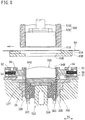
- the first punch 51A and the second punch 52A push part of the sheet metal 89 on the first die 60A into the through hole 61A of the first die 60A, thereby punching out a plate-like workpiece 90A from the sheet metal 89 (see Fig. 9 ).
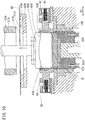
- the second punch 52A extends downward from the first punch 51A, to push the workpiece 90A into the through hole 61B of the second die 60B where the workpiece 90A is shaped to be a cylindrical workpiece 90B (see Fig. 10 ).
- the first breaking mechanism 153 breaks transmission of the biasing force from the first biasing mechanism 151 to the knockout pin 53X.
- the second breaking mechanism 154 restricts the knockout pin 53X from shifting upward.
- the pushing plate 53Y is housed in the recessed part 38D of the block body 38.
- the knockout pin 53X pushes down the block body 38, to expel the block body 38 from between the pair of fingers 94.
- the structure according to the present embodiment also attains the operation and effect similar to those of the first embodiment.
- Figs. 11 to 14 show a transfer press machine 10B according to the present embodiment. While the transfer press machine 10B is not entirely shown in the drawings, it is substantially similarly structured to the transfer press machine 10A according to the second embodiment (see Fig. 7 ), and includes the workpiece feeding apparatus 45A and the plurality of process stages ST.
- the transfer press machine 10B gradually draws, through the plurality of process stages ST, the oval-cylindrical-shaped workpiece 90B punched by the workpiece feeding apparatus 45A, so that the workpiece 90B is shaped to be a rectangular cylinder having an elongated rectangular cross section before it reaches the final process stage ST.
- the workpiece 90B is pushed down to the discharge position below the die 13 so as to avoid any scratches on the surface of the workpiece 90B. Then, the workpiece 90B is discharged beside the transfer press machine 10B from the discharge position.
- a conveyor apparatus 91W for laterally conveying the workpiece 90B having been pushed down to the discharge position, and a pair of engaging hooks 202 for releasing the punch 15 from the workpiece 90B at the discharge position.
- the conveyor apparatus 91W includes the pair of rails 92 with the pair of fingers 94.
- the pair of fingers 94 is opened and closed by air cylinders 200.
- the plurality of pairs of fingers 94 of the transfer apparatus 91 are also opened and closed by the air cylinders 200.
- the pair of engaging hooks 202 is also opened and closed by the air cylinders 200.
- a knockout pin 53Z of the final process stage ST includes just the first and second projection parts 56A, 56B out of the first to third projection parts 56A to 56C of the knockout pin 53 described in the first embodiment (see Fig. 2 ).
- the second projection part 56B is disposed at the lower end of the knockout pin 53Z.
- a first biasing mechanism 151V is provided coaxially below the knockout pin 53Z.
- the first biasing mechanism 151V is different from the first biasing mechanism 151 according to the first embodiment in that the first compression coil spring 73 is replaced by compressed air as an elastic member.
- the present embodiment includes a first breaking mechanism 153V and a second breaking mechanism 154V respectively driven by servomotors 303X, 303Y.
- the first breaking mechanism 153V includes a supporting base 309 extending between the front surface of the bolster supporting wall 12 and the upper surface of the mount part 11D.
- the lower end and the position near the upper end of a ball screw 300A of a ball screw mechanism 300 are rotatably supported by the supporting base 309.
- the servomotor 303X is disposed in parallel to the ball screw 300A and fixed to the supporting base 309.
- the output shaft of the servomotor 303X and the upper end of the ball screw 300A are coupled to each other via a pulley 304 and a timing belt 305.
- the surface facing the first biasing mechanism 151V is provided with a pair of guide rails 301 which extends in the vertical direction.
- a plurality of sliders 302A slidably engage with the pair of guide rails 301.
- a ball nut 300B of the ball screw mechanism 300 is fixed to an up-and-down base 302 to which the sliders 302A are fixed.
- a first intervention member 306X horizontally extends from the up-and-down base 302. To the through hole vertically penetrating through the tip of the first intervention member 306X, the upper end of the push-up rod 115 is fitted. To the upper end of the push-up rod 115, a pair of flanges 115A, 115B is provided so as to be vertically juxtaposed to each other. The first intervention member 306X is disposed between the flanges 115A, 115B. Thus, as shown in Fig. 14 , the first intervention member 306X shifts upward and downward using the servomotor 303X as a drive source. Then, the first intervention member 306X pushes down the push-up rod 115 (specifically, the flange 115B), to break the transmission of the biasing force from the first biasing mechanism 151V to the knockout pin 53Z.
- the second breaking mechanism 154V is disposed on the side opposite to the first breaking mechanism 153V interposing the bolster supporting wall 12 therebetween.
- the second breaking mechanism 154V is similarly structured to the first breaking mechanism 153V, and the second intervention member 306Y shifts upward and downward using the servomotor 303Y as a drive source.
- the portion between the first and second projection parts 56A, 56B in the knockout pin 53Z penetrates through the through hole at the tip of the second intervention member 306Y.
- the second intervention member 306Y pushes down the knockout pin 53Z (specifically, the second projection part 56B), to break the transmission of the biasing force from the knockout pin 53Z to the workpiece 90B.
- the second compression coil spring 83 is provided around the portion between the second intervention member 306Y and the first projection part 56A in the knockout pin 53Z.
- the second compression coil spring 83, the first projection part 56A, and the second intervention member 306Y constitute the second biasing mechanism 152V.
- the punch 15 and the knockout pin 53Z shift downward toward the die 13 holding the workpiece 90B between them.
- the knockout pin 53Z receiving the biasing force from the two, namely, the first and second biasing mechanisms 151V, 152V pushes up the workpiece 90B from beneath, to prevent the workpiece 90B from bulging deformation.
- the first breaking mechanism 153V separates the push-up rod 115 of the first biasing mechanism 151V from the knockout pin 53Z.
- the workpiece 90B shifts downward to the discharge position in the state where the punch 15 and the workpiece 90B are less pushed by the knockout pin 53Z.
- the second breaking mechanism 154V restricts the knockout pin 53Z from shifting upward, whereby the workpiece 90B is laterally discharged.
- the biasing force from the second biasing mechanism 152V to the knockout pin 53Z can also be changed.
- the transfer press machine according to the present embodiment is substantially similarly structured to the transfer press machine 10 according to the first embodiment.
- the workpiece feeding apparatus 45B according to the present embodiment is identical to the workpiece feeding apparatus 45 according to the first embodiment in the following points. That is, as shown in Fig. 15 , in the state where the knockout pin 130 abuts on the lower surface of part of the sheet metal 89, the workpiece feeding apparatus 45B according to the present embodiment causes the first punch 51 of the composite punch 50 to push part of the sheet metal 89 into the through hole 61 of the die 60, to punch out the workpiece 90. Thereafter, the workpiece 90 held between the second punch 52 extending downward from the first punch 51 and the knockout pin 130 shifts downward.
- the knockout pin 130 further shifts downward from the position where the workpiece 90 engages with the engaging grooves 94A of the pair of fingers 94, and the second punch 52 shifts upward. After the knockout pin 130 and the second punch 52 are retracted from between the pair of fingers 94, the pair of fingers 94 conveys the workpiece 90 to the process stages ST.
- the first and second biasing mechanisms 151, 152 and the first and second breaking mechanisms 153, 154 described in the first embodiment are provided, which operate similarly as in the first embodiment.
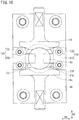
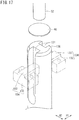
- the workpiece feeding apparatus 45B according to the present embodiment is different from the workpiece feeding apparatus 45 according to the first embodiment in the following points . That is, as shown in Fig. 17 , a pair of vertical grooves 131 is formed at the circumferential surface of the knockout pin 130, at two positions spaced apart from each other by 180 degrees in the circumferential direction.
- the vertical grooves 131 are each quadrangular groove-shaped, and open also to the upper surface of the knockout pin 130.
- the pair of vertical grooves 131 is disposed so as to be juxtaposed to each other in the direction perpendicular to the direction in which the pair of fingers 94 opposes to each other.
- a pair of workpiece coming-off preventing members 134 is provided at two positions interposing the knockout pin 130 therebetween in the direction perpendicular to the direction in which the fingers 94 oppose to each other.
- the workpiece coming-off preventing members 134 each have a structure including a supporting block 132 of a rectangular shape and an engaging part 133 projecting from the supporting block 132.
- the supporting block 132 is fixed to the die holder 48. While not shown in the drawings, the upper surface of the supporting block 132 is positioned at a level identical to or slightly lower than the lower surface of the finger 94.
- the engaging part 133 is rectangular-parallelepiped shaped extending in the direction perpendicular to the direction in which the pair of fingers 94 opposes to each other, and projects from the lateral surface and the upper surface of the supporting block 132 to engage with the vertical groove 131 of the knockout pin 130. While not shown in the drawings, the upper surface of the engaging part 133 is disposed at a level identical to or slightly lower than the lower surface of the workpiece 90 engaging with the engaging grooves 94A of the pair of fingers 94.
- the knockout pin 130 becomes separated from the workpiece 90 after having been held between the pair of fingers 94
- the pair of workpiece coming-off preventing members 134 prevents the workpiece 90 from coming off. Note that, when the pair of fingers 94 shifts in the conveying direction, the engaging part 133 passes without interfering with the pair of fingers 94.
Landscapes
- Engineering & Computer Science (AREA)
- Mechanical Engineering (AREA)
- Punching Or Piercing (AREA)
- Press Drives And Press Lines (AREA)
Claims (4)
- Pressvorrichtung (45) mit einem Stempel (50) und einem Ausstoßstift (53), die dazu ausgebildet sind, ein Werkstück (90) zwischen sich zu halten und sich zum Ausführen von Pressarbeit auf dem Werkstück (90) nach unten zu einer Matrize (60) zu verschieben, welcher Stempel (50) und welcher Ausstoßstift (53) dazu ausgebildet sind, sich zu einer Ausgabeposition unterhalb der Matrize (60) zu verschieben, von wo das Werkstück (90) lateral ausgegeben wird, welche Pressvorrichtung (45) dadurch gekennzeichnet ist, dass sie ferner aufweist:einen ersten Vorspannmechanismus (151), der dazu ausgebildet ist, eine erste Vorspannkraft nach oben auf den Ausstoßstift (53) auszuüben;einen zweiten Vorspannmechanismus (152), der dazu ausgebildet ist, eine zweite Vorspannkraft nach oben auf den Ausstoßstift (53) auszuüben;dadurch gekennzeichnet, dass sie fernereinen ersten Unterbrechungsmechanismus (153), der dazu ausgebildet ist, unmittelbar nach der Pressarbeit auf dem Werkstück (90) mit dem ersten Vorspannmechanismus (151) in Eingriff zu kommen, so dass eine Verschiebung nach oben eingeschränkt wird und eine Übertragung von Kraft von dem ersten Vorspannmechanismus (151) an den Ausstoßstift (53) unterbrochen wird; undeinen zweiten Unterbrechungsmechanismus (154), der dazu ausgebildet ist, nachdem das Werkstück (90) die Ausgabeposition erreicht, mit dem Ausstoßstift (53) derart in Eingriff zu kommen, dass eine Verschiebung nach oben eingeschränkt wird und eine Übertragung von Kraft von dem Ausstoßstift (53) an das Werkstück (90) unterbrochen wird, aufweist.
- Pressvorrichtung (45) nach Anspruch 1, dadurch gekennzeichnet, dass der Stempel (50) ein zusammengesetzter Stempel (50) ist, der aus einem zylindrischen ersten Stempel (51) und einem zweiten Stempel (52), der in den ersten Stempel (51) eingefügt ist, ausgebildet ist,die Pressarbeit Stanzarbeit ist, bei der ein Teil eines Metallblechs (89), das auf einer oberen Oberfläche der Matrize (60) angeordnet ist, dazu ausgebildet ist, zwischen dem ersten Stempel (51) und dem Ausstoßstift (53) gehalten zu werden und als das Werkstück (90) ausgestanzt zu werden, undder zweite Stempel (52) dazu ausgebildet ist, sich unmittelbar nach der Stanzarbeit von innerhalb des ersten Stempels (51) zum Halten des Werkstücks (90) zwischen dem zweiten Stempel (52) und dem Ausstoßstift (53) nach unten zu erstrecken, so dass er sich zu der Ausgabeposition verschiebt.
- Pressvorrichtung (45) nach Anspruch 1 oder 2, dadurch gekennzeichnet, dass der erste Vorspannmechanismus (151)eine Hochschiebestange (115), die auf einer Verlängerung von dem Ausstoßstift (53) nach unten angeordnet ist und vertikal verschiebbar gelagert ist, undein elastisches Bauteil (73), das eine Kompressionsschraubenfeder oder komprimierte Luft aufweist, das so wirkt, dass es die Hochschiebestange (115) nach oben vorspannt, aufweist,
der zweite Vorspannmechanismus (152)eine Kompressionsschraubenfeder (83), die an dem Ausstoßstift (53) vorgesehen ist,einen Federoberseitenanlageteil (56A), der an dem Ausstoßstift (53) so vorgesehen ist, dass er an der Kompressionsschraubenfeder (83) von oben anliegt, undeinen Federunterseitenanlageteil (113), der dazu ausgebildet ist, an der Kompressionsschraubenfeder (83) von unten anzuliegen, aufweist. - Pressvorrichtung (45) nach Anspruch 3, dadurch gekennzeichnet, dass sie ferner erste und zweite Nocken (42A, 42B) aufweist, die dazu ausgebildet sind, sich mit einer Nockenwelle (42), die sich horizontal erstreckt, integral zu drehen, bei der der erste Unterbrechungsmechanismus (153) einen ersten Hebel (44A) aufweist, der dazu ausgebildet ist, dem ersten Nocken (42A) zu folgen, so dass er sich zwischen einer Position zum Einschränken eines oberen Endes der Hochschiebestange (115) darin, sich nach oben zu verschieben, und einer Position zum Aufheben der Einschränkung dreht,
der zweite Unterbrechungsmechanismus (154)eine Hilfsstange (57), die so angeordnet ist, dass sie neben den Ausstoßstift (53) gestellt ist, und die sich vertikal erstreckt, während sie vertikal verschiebbar gelagert ist,ein Interventionsbauteil (58), das an der Hilfsstange (57) befestigt ist und in Richtung des Ausstoßstifts (53) vorsteht, das ein Durchgangsloch (58A) aufweist, das ein Abschnitt in dem Ausstoßstift (53) unter dem Federunterseitenanlageteil (113) durchdringt,einen abgestuften Vorsprungsteil (56B), der an dem Ausstoßstift (53) so vorgesehen ist, dass er dem Interventionsbauteil (58) von unten gegenüberliegt, undeinen zweiten Hebel (44B), der dazu ausgebildet ist, dem zweiten Nocken (42B) zu folgen, so dass er sich zwischen einer Position zum Einschränken eines unteren Endes der Hilfsstange (57) darin, sich nach oben zu verschieben, und einer Position zum Aufheben der Einschränkung dreht, aufweist.
Applications Claiming Priority (1)
| Application Number | Priority Date | Filing Date | Title |
|---|---|---|---|
| JP2019140717A JP6676815B1 (ja) | 2019-07-31 | 2019-07-31 | プレス装置 |
Publications (2)
| Publication Number | Publication Date |
|---|---|
| EP3771504A1 EP3771504A1 (de) | 2021-02-03 |
| EP3771504B1 true EP3771504B1 (de) | 2021-10-06 |
Family
ID=70057911
Family Applications (1)
| Application Number | Title | Priority Date | Filing Date |
|---|---|---|---|
| EP20179905.3A Active EP3771504B1 (de) | 2019-07-31 | 2020-06-15 | Pressvorrichtung |
Country Status (4)
| Country | Link |
|---|---|
| EP (1) | EP3771504B1 (de) |
| JP (1) | JP6676815B1 (de) |
| KR (1) | KR102178570B1 (de) |
| CN (1) | CN111659789B (de) |
Families Citing this family (12)
| Publication number | Priority date | Publication date | Assignee | Title |
|---|---|---|---|---|
| IT202000013117A1 (it) * | 2020-06-03 | 2021-12-03 | Corrada Spa | Dispositivo freno per la realizzazione di pacchi lamellari ad uso elettrico |
| CN114981024A (zh) * | 2020-12-23 | 2022-08-30 | 东芝三菱电机产业系统株式会社 | 冲压加工装置 |
| KR102394540B1 (ko) | 2021-01-11 | 2022-05-06 | (주)아이제이에스 | 에어 녹아웃 장치 |
| JP7337867B2 (ja) * | 2021-03-17 | 2023-09-04 | 旭精機工業株式会社 | ダイセット、筒形ワーク生成装置及びトランスファプレス機 |
| CN114160703B (zh) * | 2022-02-09 | 2022-05-13 | 宁波世纪东港机械有限公司 | 一种汽车前副支架的一体化生产线 |
| JP7210124B1 (ja) * | 2022-03-30 | 2023-01-23 | 旭精機工業株式会社 | プレス機 |
| JP7597086B2 (ja) | 2022-07-28 | 2024-12-10 | 東洋製罐株式会社 | 缶の製造方法及び製造システム |
| CN115647161A (zh) * | 2022-08-18 | 2023-01-31 | 合肥合锻智能制造股份有限公司 | 一种新型自动脱料间接热成型装置 |
| CN116727528A (zh) * | 2023-06-08 | 2023-09-12 | 福建佳鑫金属科技有限公司 | 一种电池铜巴的冲切模具 |
| CN117019964B (zh) * | 2023-08-04 | 2026-02-24 | 深圳市冠华珠宝有限公司 | 一种能够自动排料的冲压设备 |
| JP7491632B1 (ja) * | 2024-01-29 | 2024-05-28 | 冨士発條株式会社 | プレスシステム、およびトランスファ装置 |
| CN118385352B (zh) * | 2024-06-26 | 2024-11-15 | 南通鑫慧达机械有限公司 | 一种用于金属工具配件的冲压加工装置 |
Family Cites Families (6)
| Publication number | Priority date | Publication date | Assignee | Title |
|---|---|---|---|---|
| JPH1128699A (ja) * | 1997-07-09 | 1999-02-02 | Mitsui High Tec Inc | 金型装置 |
| JP3435321B2 (ja) * | 1997-09-18 | 2003-08-11 | 旭精機工業株式会社 | トランスファプレスの絞り成形方法並びにトランスファプレス |
| JP4185786B2 (ja) * | 2003-02-27 | 2008-11-26 | 旭精機工業株式会社 | プレス機械のノックアウト装置 |
| JP5777192B1 (ja) * | 2015-04-23 | 2015-09-09 | 旭精機工業株式会社 | トランスファプレス機 |
| JP6544831B2 (ja) * | 2016-10-21 | 2019-07-17 | 旭精機工業株式会社 | プレス機 |
| CN108906949B (zh) * | 2018-09-14 | 2023-09-15 | 苏州轴承厂股份有限公司 | 冲压外圈一次成型翻边装置 |
-
2019
- 2019-07-31 JP JP2019140717A patent/JP6676815B1/ja active Active
-
2020
- 2020-04-13 KR KR1020200044431A patent/KR102178570B1/ko active Active
- 2020-06-15 EP EP20179905.3A patent/EP3771504B1/de active Active
- 2020-06-16 CN CN202010551040.0A patent/CN111659789B/zh active Active
Also Published As
| Publication number | Publication date |
|---|---|
| CN111659789B (zh) | 2021-05-18 |
| KR102178570B1 (ko) | 2020-11-13 |
| CN111659789A (zh) | 2020-09-15 |
| JP6676815B1 (ja) | 2020-04-08 |
| JP2021023942A (ja) | 2021-02-22 |
| EP3771504A1 (de) | 2021-02-03 |
Similar Documents
| Publication | Publication Date | Title |
|---|---|---|
| EP3771504A1 (de) | Pressvorrichtung | |
| EP3756784A1 (de) | Werkstückentnahmevorrichtung und transferpressmaschine | |
| EP4260959B1 (de) | Matrizenträgermechanismus, vorrichtung zur erzeugung eines zylindrischen werkstücks und transferpresse | |
| JP2020189296A (ja) | プレス機及びプレス成形方法 | |
| GB1156938A (en) | Improvements in Die Presses | |
| KR20050092043A (ko) | 순차이송 성형되는 시트 금속의 원 상태의 레벨링을 위한방법 및 장치 | |
| US5865057A (en) | Work transfer in multi-stage forging apparatus | |
| CA2707416C (en) | Method and arrangement for production of stampings | |
| JP3216574B2 (ja) | プレス型 | |
| JP7252682B1 (ja) | プレスシステム、トランスファプレスシステム、トランスファ装置、及び金型 | |
| JP7286260B2 (ja) | トランスファプレス機 | |
| US3782231A (en) | Piercing assembly | |
| JP7019267B2 (ja) | プレス機 | |
| JP2767462B2 (ja) | トランスフアープレス機におけるチヤツクタイミング装置 | |
| JP4700382B2 (ja) | トランスファ装置 | |
| JP2022115157A (ja) | トランスファプレス機 | |
| US1908563A (en) | Punch press | |
| JP4232965B2 (ja) | トランスファ装置 | |
| JP4093368B2 (ja) | トランスファ装置 | |
| JP3704033B2 (ja) | トランスファスライドにおけるワーク送り量調整装置 | |
| US1382463A (en) | Machine for producing spring dress-fasteners | |
| US6578402B2 (en) | Trimming apparatus for a drawn part | |
| CN121589210A (zh) | 一种机床门铰链加工模具 | |
| JP5163554B2 (ja) | プレス装置 | |
| US211407A (en) | Improvement in machines for cutting, drawing |
Legal Events
| Date | Code | Title | Description |
|---|---|---|---|
| PUAI | Public reference made under article 153(3) epc to a published international application that has entered the european phase |
Free format text: ORIGINAL CODE: 0009012 |
|
| STAA | Information on the status of an ep patent application or granted ep patent |
Free format text: STATUS: REQUEST FOR EXAMINATION WAS MADE |
|
| 17P | Request for examination filed |
Effective date: 20200615 |
|
| AK | Designated contracting states |
Kind code of ref document: A1 Designated state(s): AL AT BE BG CH CY CZ DE DK EE ES FI FR GB GR HR HU IE IS IT LI LT LU LV MC MK MT NL NO PL PT RO RS SE SI SK SM TR |
|
| AX | Request for extension of the european patent |
Extension state: BA ME |
|
| GRAP | Despatch of communication of intention to grant a patent |
Free format text: ORIGINAL CODE: EPIDOSNIGR1 |
|
| STAA | Information on the status of an ep patent application or granted ep patent |
Free format text: STATUS: GRANT OF PATENT IS INTENDED |
|
| RIC1 | Information provided on ipc code assigned before grant |
Ipc: B21D 45/02 20060101AFI20210614BHEP Ipc: B21D 45/04 20060101ALI20210614BHEP Ipc: B21D 22/21 20060101ALI20210614BHEP Ipc: B21D 28/14 20060101ALI20210614BHEP Ipc: B21D 43/05 20060101ALI20210614BHEP |
|
| INTG | Intention to grant announced |
Effective date: 20210630 |
|
| GRAS | Grant fee paid |
Free format text: ORIGINAL CODE: EPIDOSNIGR3 |
|
| GRAA | (expected) grant |
Free format text: ORIGINAL CODE: 0009210 |
|
| STAA | Information on the status of an ep patent application or granted ep patent |
Free format text: STATUS: THE PATENT HAS BEEN GRANTED |
|
| AK | Designated contracting states |
Kind code of ref document: B1 Designated state(s): AL AT BE BG CH CY CZ DE DK EE ES FI FR GB GR HR HU IE IS IT LI LT LU LV MC MK MT NL NO PL PT RO RS SE SI SK SM TR |
|
| REG | Reference to a national code |
Ref country code: GB Ref legal event code: FG4D |
|
| REG | Reference to a national code |
Ref country code: CH Ref legal event code: EP Ref country code: AT Ref legal event code: REF Ref document number: 1435778 Country of ref document: AT Kind code of ref document: T Effective date: 20211015 |
|
| REG | Reference to a national code |
Ref country code: IE Ref legal event code: FG4D |
|
| REG | Reference to a national code |
Ref country code: DE Ref legal event code: R096 Ref document number: 602020000681 Country of ref document: DE |
|
| REG | Reference to a national code |
Ref country code: LT Ref legal event code: MG9D |
|
| REG | Reference to a national code |
Ref country code: NL Ref legal event code: MP Effective date: 20211006 |
|
| REG | Reference to a national code |
Ref country code: AT Ref legal event code: MK05 Ref document number: 1435778 Country of ref document: AT Kind code of ref document: T Effective date: 20211006 |
|
| PG25 | Lapsed in a contracting state [announced via postgrant information from national office to epo] |
Ref country code: RS Free format text: LAPSE BECAUSE OF FAILURE TO SUBMIT A TRANSLATION OF THE DESCRIPTION OR TO PAY THE FEE WITHIN THE PRESCRIBED TIME-LIMIT Effective date: 20211006 Ref country code: LT Free format text: LAPSE BECAUSE OF FAILURE TO SUBMIT A TRANSLATION OF THE DESCRIPTION OR TO PAY THE FEE WITHIN THE PRESCRIBED TIME-LIMIT Effective date: 20211006 Ref country code: FI Free format text: LAPSE BECAUSE OF FAILURE TO SUBMIT A TRANSLATION OF THE DESCRIPTION OR TO PAY THE FEE WITHIN THE PRESCRIBED TIME-LIMIT Effective date: 20211006 Ref country code: BG Free format text: LAPSE BECAUSE OF FAILURE TO SUBMIT A TRANSLATION OF THE DESCRIPTION OR TO PAY THE FEE WITHIN THE PRESCRIBED TIME-LIMIT Effective date: 20220106 Ref country code: AT Free format text: LAPSE BECAUSE OF FAILURE TO SUBMIT A TRANSLATION OF THE DESCRIPTION OR TO PAY THE FEE WITHIN THE PRESCRIBED TIME-LIMIT Effective date: 20211006 |
|
| PG25 | Lapsed in a contracting state [announced via postgrant information from national office to epo] |
Ref country code: IS Free format text: LAPSE BECAUSE OF FAILURE TO SUBMIT A TRANSLATION OF THE DESCRIPTION OR TO PAY THE FEE WITHIN THE PRESCRIBED TIME-LIMIT Effective date: 20220206 Ref country code: SE Free format text: LAPSE BECAUSE OF FAILURE TO SUBMIT A TRANSLATION OF THE DESCRIPTION OR TO PAY THE FEE WITHIN THE PRESCRIBED TIME-LIMIT Effective date: 20211006 Ref country code: PT Free format text: LAPSE BECAUSE OF FAILURE TO SUBMIT A TRANSLATION OF THE DESCRIPTION OR TO PAY THE FEE WITHIN THE PRESCRIBED TIME-LIMIT Effective date: 20220207 Ref country code: PL Free format text: LAPSE BECAUSE OF FAILURE TO SUBMIT A TRANSLATION OF THE DESCRIPTION OR TO PAY THE FEE WITHIN THE PRESCRIBED TIME-LIMIT Effective date: 20211006 Ref country code: NO Free format text: LAPSE BECAUSE OF FAILURE TO SUBMIT A TRANSLATION OF THE DESCRIPTION OR TO PAY THE FEE WITHIN THE PRESCRIBED TIME-LIMIT Effective date: 20220106 Ref country code: NL Free format text: LAPSE BECAUSE OF FAILURE TO SUBMIT A TRANSLATION OF THE DESCRIPTION OR TO PAY THE FEE WITHIN THE PRESCRIBED TIME-LIMIT Effective date: 20211006 Ref country code: LV Free format text: LAPSE BECAUSE OF FAILURE TO SUBMIT A TRANSLATION OF THE DESCRIPTION OR TO PAY THE FEE WITHIN THE PRESCRIBED TIME-LIMIT Effective date: 20211006 Ref country code: HR Free format text: LAPSE BECAUSE OF FAILURE TO SUBMIT A TRANSLATION OF THE DESCRIPTION OR TO PAY THE FEE WITHIN THE PRESCRIBED TIME-LIMIT Effective date: 20211006 Ref country code: GR Free format text: LAPSE BECAUSE OF FAILURE TO SUBMIT A TRANSLATION OF THE DESCRIPTION OR TO PAY THE FEE WITHIN THE PRESCRIBED TIME-LIMIT Effective date: 20220107 Ref country code: ES Free format text: LAPSE BECAUSE OF FAILURE TO SUBMIT A TRANSLATION OF THE DESCRIPTION OR TO PAY THE FEE WITHIN THE PRESCRIBED TIME-LIMIT Effective date: 20211006 |
|
| REG | Reference to a national code |
Ref country code: DE Ref legal event code: R097 Ref document number: 602020000681 Country of ref document: DE |
|
| PG25 | Lapsed in a contracting state [announced via postgrant information from national office to epo] |
Ref country code: SM Free format text: LAPSE BECAUSE OF FAILURE TO SUBMIT A TRANSLATION OF THE DESCRIPTION OR TO PAY THE FEE WITHIN THE PRESCRIBED TIME-LIMIT Effective date: 20211006 Ref country code: SK Free format text: LAPSE BECAUSE OF FAILURE TO SUBMIT A TRANSLATION OF THE DESCRIPTION OR TO PAY THE FEE WITHIN THE PRESCRIBED TIME-LIMIT Effective date: 20211006 Ref country code: RO Free format text: LAPSE BECAUSE OF FAILURE TO SUBMIT A TRANSLATION OF THE DESCRIPTION OR TO PAY THE FEE WITHIN THE PRESCRIBED TIME-LIMIT Effective date: 20211006 Ref country code: EE Free format text: LAPSE BECAUSE OF FAILURE TO SUBMIT A TRANSLATION OF THE DESCRIPTION OR TO PAY THE FEE WITHIN THE PRESCRIBED TIME-LIMIT Effective date: 20211006 Ref country code: DK Free format text: LAPSE BECAUSE OF FAILURE TO SUBMIT A TRANSLATION OF THE DESCRIPTION OR TO PAY THE FEE WITHIN THE PRESCRIBED TIME-LIMIT Effective date: 20211006 Ref country code: CZ Free format text: LAPSE BECAUSE OF FAILURE TO SUBMIT A TRANSLATION OF THE DESCRIPTION OR TO PAY THE FEE WITHIN THE PRESCRIBED TIME-LIMIT Effective date: 20211006 |
|
| PLBE | No opposition filed within time limit |
Free format text: ORIGINAL CODE: 0009261 |
|
| STAA | Information on the status of an ep patent application or granted ep patent |
Free format text: STATUS: NO OPPOSITION FILED WITHIN TIME LIMIT |
|
| 26N | No opposition filed |
Effective date: 20220707 |
|
| PG25 | Lapsed in a contracting state [announced via postgrant information from national office to epo] |
Ref country code: AL Free format text: LAPSE BECAUSE OF FAILURE TO SUBMIT A TRANSLATION OF THE DESCRIPTION OR TO PAY THE FEE WITHIN THE PRESCRIBED TIME-LIMIT Effective date: 20211006 |
|
| PG25 | Lapsed in a contracting state [announced via postgrant information from national office to epo] |
Ref country code: MC Free format text: LAPSE BECAUSE OF FAILURE TO SUBMIT A TRANSLATION OF THE DESCRIPTION OR TO PAY THE FEE WITHIN THE PRESCRIBED TIME-LIMIT Effective date: 20211006 |
|
| REG | Reference to a national code |
Ref country code: BE Ref legal event code: MM Effective date: 20220630 |
|
| PG25 | Lapsed in a contracting state [announced via postgrant information from national office to epo] |
Ref country code: LU Free format text: LAPSE BECAUSE OF NON-PAYMENT OF DUE FEES Effective date: 20220615 Ref country code: IE Free format text: LAPSE BECAUSE OF NON-PAYMENT OF DUE FEES Effective date: 20220615 Ref country code: FR Free format text: LAPSE BECAUSE OF NON-PAYMENT OF DUE FEES Effective date: 20220630 |
|
| PG25 | Lapsed in a contracting state [announced via postgrant information from national office to epo] |
Ref country code: IT Free format text: LAPSE BECAUSE OF FAILURE TO SUBMIT A TRANSLATION OF THE DESCRIPTION OR TO PAY THE FEE WITHIN THE PRESCRIBED TIME-LIMIT Effective date: 20211006 Ref country code: BE Free format text: LAPSE BECAUSE OF NON-PAYMENT OF DUE FEES Effective date: 20220630 |
|
| REG | Reference to a national code |
Ref country code: CH Ref legal event code: PL |
|
| PG25 | Lapsed in a contracting state [announced via postgrant information from national office to epo] |
Ref country code: MK Free format text: LAPSE BECAUSE OF FAILURE TO SUBMIT A TRANSLATION OF THE DESCRIPTION OR TO PAY THE FEE WITHIN THE PRESCRIBED TIME-LIMIT Effective date: 20211006 Ref country code: CY Free format text: LAPSE BECAUSE OF FAILURE TO SUBMIT A TRANSLATION OF THE DESCRIPTION OR TO PAY THE FEE WITHIN THE PRESCRIBED TIME-LIMIT Effective date: 20211006 Ref country code: CH Free format text: LAPSE BECAUSE OF NON-PAYMENT OF DUE FEES Effective date: 20230630 |
|
| PG25 | Lapsed in a contracting state [announced via postgrant information from national office to epo] |
Ref country code: HU Free format text: LAPSE BECAUSE OF FAILURE TO SUBMIT A TRANSLATION OF THE DESCRIPTION OR TO PAY THE FEE WITHIN THE PRESCRIBED TIME-LIMIT; INVALID AB INITIO Effective date: 20200615 |
|
| PG25 | Lapsed in a contracting state [announced via postgrant information from national office to epo] |
Ref country code: MT Free format text: LAPSE BECAUSE OF FAILURE TO SUBMIT A TRANSLATION OF THE DESCRIPTION OR TO PAY THE FEE WITHIN THE PRESCRIBED TIME-LIMIT Effective date: 20211006 |
|
| GBPC | Gb: european patent ceased through non-payment of renewal fee |
Effective date: 20240615 |
|
| PG25 | Lapsed in a contracting state [announced via postgrant information from national office to epo] |
Ref country code: GB Free format text: LAPSE BECAUSE OF NON-PAYMENT OF DUE FEES Effective date: 20240615 |
|
| PGFP | Annual fee paid to national office [announced via postgrant information from national office to epo] |
Ref country code: DE Payment date: 20250618 Year of fee payment: 6 |
|
| PG25 | Lapsed in a contracting state [announced via postgrant information from national office to epo] |
Ref country code: TR Free format text: LAPSE BECAUSE OF FAILURE TO SUBMIT A TRANSLATION OF THE DESCRIPTION OR TO PAY THE FEE WITHIN THE PRESCRIBED TIME-LIMIT Effective date: 20211006 |
|
| PG25 | Lapsed in a contracting state [announced via postgrant information from national office to epo] |
Ref country code: SI Free format text: LAPSE BECAUSE OF FAILURE TO SUBMIT A TRANSLATION OF THE DESCRIPTION OR TO PAY THE FEE WITHIN THE PRESCRIBED TIME-LIMIT Effective date: 20211006 |