EP3760260A1 - Kolbenstange mit wenigstens drei ringelelementen für eine vorgefüllte spritze - Google Patents
Kolbenstange mit wenigstens drei ringelelementen für eine vorgefüllte spritze Download PDFInfo
- Publication number
- EP3760260A1 EP3760260A1 EP20186074.9A EP20186074A EP3760260A1 EP 3760260 A1 EP3760260 A1 EP 3760260A1 EP 20186074 A EP20186074 A EP 20186074A EP 3760260 A1 EP3760260 A1 EP 3760260A1
- Authority
- EP
- European Patent Office
- Prior art keywords
- piston rod
- syringe
- piston
- syringe body
- ring elements
- Prior art date
- Legal status (The legal status is an assumption and is not a legal conclusion. Google has not performed a legal analysis and makes no representation as to the accuracy of the status listed.)
- Pending
Links
- 229940071643 prefilled syringe Drugs 0.000 title claims abstract description 28
- 239000007788 liquid Substances 0.000 claims abstract description 14
- 239000004033 plastic Substances 0.000 description 5
- OLBCVFGFOZPWHH-UHFFFAOYSA-N propofol Chemical compound CC(C)C1=CC=CC(C(C)C)=C1O OLBCVFGFOZPWHH-UHFFFAOYSA-N 0.000 description 5
- 229920000089 Cyclic olefin copolymer Polymers 0.000 description 4
- 229920000642 polymer Polymers 0.000 description 4
- 229960004134 propofol Drugs 0.000 description 4
- 239000012530 fluid Substances 0.000 description 3
- 239000013078 crystal Substances 0.000 description 2
- 150000001925 cycloalkenes Chemical class 0.000 description 2
- 239000000839 emulsion Substances 0.000 description 2
- 238000004806 packaging method and process Methods 0.000 description 2
- 239000002904 solvent Substances 0.000 description 2
- 230000000087 stabilizing effect Effects 0.000 description 2
- 230000007704 transition Effects 0.000 description 2
- 239000004743 Polypropylene Substances 0.000 description 1
- 239000004480 active ingredient Substances 0.000 description 1
- QVGXLLKOCUKJST-UHFFFAOYSA-N atomic oxygen Chemical compound [O] QVGXLLKOCUKJST-UHFFFAOYSA-N 0.000 description 1
- 230000001419 dependent effect Effects 0.000 description 1
- 229940079593 drug Drugs 0.000 description 1
- 239000003814 drug Substances 0.000 description 1
- 238000001802 infusion Methods 0.000 description 1
- 238000003780 insertion Methods 0.000 description 1
- 230000037431 insertion Effects 0.000 description 1
- 239000000314 lubricant Substances 0.000 description 1
- 229910052760 oxygen Inorganic materials 0.000 description 1
- 239000001301 oxygen Substances 0.000 description 1
- 235000016236 parenteral nutrition Nutrition 0.000 description 1
- -1 polypropylene Polymers 0.000 description 1
- 229920001155 polypropylene Polymers 0.000 description 1
- 239000000126 substance Substances 0.000 description 1
Images

Classifications
-
- A—HUMAN NECESSITIES
- A61—MEDICAL OR VETERINARY SCIENCE; HYGIENE
- A61M—DEVICES FOR INTRODUCING MEDIA INTO, OR ONTO, THE BODY; DEVICES FOR TRANSDUCING BODY MEDIA OR FOR TAKING MEDIA FROM THE BODY; DEVICES FOR PRODUCING OR ENDING SLEEP OR STUPOR
- A61M5/00—Devices for bringing media into the body in a subcutaneous, intra-vascular or intramuscular way; Accessories therefor, e.g. filling or cleaning devices, arm-rests
- A61M5/178—Syringes
- A61M5/31—Details
- A61M5/315—Pistons; Piston-rods; Guiding, blocking or restricting the movement of the rod or piston; Appliances on the rod for facilitating dosing ; Dosing mechanisms
- A61M5/31511—Piston or piston-rod constructions, e.g. connection of piston with piston-rod
- A61M5/31515—Connection of piston with piston rod
-
- A—HUMAN NECESSITIES
- A61—MEDICAL OR VETERINARY SCIENCE; HYGIENE
- A61M—DEVICES FOR INTRODUCING MEDIA INTO, OR ONTO, THE BODY; DEVICES FOR TRANSDUCING BODY MEDIA OR FOR TAKING MEDIA FROM THE BODY; DEVICES FOR PRODUCING OR ENDING SLEEP OR STUPOR
- A61M5/00—Devices for bringing media into the body in a subcutaneous, intra-vascular or intramuscular way; Accessories therefor, e.g. filling or cleaning devices, arm-rests
- A61M5/002—Packages specially adapted therefor, e.g. for syringes or needles, kits for diabetics
-
- A—HUMAN NECESSITIES
- A61—MEDICAL OR VETERINARY SCIENCE; HYGIENE
- A61M—DEVICES FOR INTRODUCING MEDIA INTO, OR ONTO, THE BODY; DEVICES FOR TRANSDUCING BODY MEDIA OR FOR TAKING MEDIA FROM THE BODY; DEVICES FOR PRODUCING OR ENDING SLEEP OR STUPOR
- A61M5/00—Devices for bringing media into the body in a subcutaneous, intra-vascular or intramuscular way; Accessories therefor, e.g. filling or cleaning devices, arm-rests
- A61M5/178—Syringes
- A61M5/28—Syringe ampoules or carpules, i.e. ampoules or carpules provided with a needle
-
- A—HUMAN NECESSITIES
- A61—MEDICAL OR VETERINARY SCIENCE; HYGIENE
- A61M—DEVICES FOR INTRODUCING MEDIA INTO, OR ONTO, THE BODY; DEVICES FOR TRANSDUCING BODY MEDIA OR FOR TAKING MEDIA FROM THE BODY; DEVICES FOR PRODUCING OR ENDING SLEEP OR STUPOR
- A61M5/00—Devices for bringing media into the body in a subcutaneous, intra-vascular or intramuscular way; Accessories therefor, e.g. filling or cleaning devices, arm-rests
- A61M5/178—Syringes
- A61M5/31—Details
- A61M5/315—Pistons; Piston-rods; Guiding, blocking or restricting the movement of the rod or piston; Appliances on the rod for facilitating dosing ; Dosing mechanisms
- A61M5/31511—Piston or piston-rod constructions, e.g. connection of piston with piston-rod
-
- B—PERFORMING OPERATIONS; TRANSPORTING
- B65—CONVEYING; PACKING; STORING; HANDLING THIN OR FILAMENTARY MATERIAL
- B65D—CONTAINERS FOR STORAGE OR TRANSPORT OF ARTICLES OR MATERIALS, e.g. BAGS, BARRELS, BOTTLES, BOXES, CANS, CARTONS, CRATES, DRUMS, JARS, TANKS, HOPPERS, FORWARDING CONTAINERS; ACCESSORIES, CLOSURES, OR FITTINGS THEREFOR; PACKAGING ELEMENTS; PACKAGES
- B65D75/00—Packages comprising articles or materials partially or wholly enclosed in strips, sheets, blanks, tubes or webs of flexible sheet material, e.g. in folded wrappers
- B65D75/28—Articles or materials wholly enclosed in composite wrappers, i.e. wrappers formed by associating or interconnecting two or more sheets or blanks
- B65D75/30—Articles or materials enclosed between two opposed sheets or blanks having their margins united, e.g. by pressure-sensitive adhesive, crimping, heat-sealing, or welding
- B65D75/32—Articles or materials enclosed between two opposed sheets or blanks having their margins united, e.g. by pressure-sensitive adhesive, crimping, heat-sealing, or welding one or both sheets or blanks being recessed to accommodate contents
- B65D75/36—Articles or materials enclosed between two opposed sheets or blanks having their margins united, e.g. by pressure-sensitive adhesive, crimping, heat-sealing, or welding one or both sheets or blanks being recessed to accommodate contents one sheet or blank being recessed and the other formed of relatively stiff flat sheet material, e.g. blister packages, the recess or recesses being preformed
- B65D75/366—Articles or materials enclosed between two opposed sheets or blanks having their margins united, e.g. by pressure-sensitive adhesive, crimping, heat-sealing, or welding one or both sheets or blanks being recessed to accommodate contents one sheet or blank being recessed and the other formed of relatively stiff flat sheet material, e.g. blister packages, the recess or recesses being preformed and forming one compartment
-
- A—HUMAN NECESSITIES
- A61—MEDICAL OR VETERINARY SCIENCE; HYGIENE
- A61M—DEVICES FOR INTRODUCING MEDIA INTO, OR ONTO, THE BODY; DEVICES FOR TRANSDUCING BODY MEDIA OR FOR TAKING MEDIA FROM THE BODY; DEVICES FOR PRODUCING OR ENDING SLEEP OR STUPOR
- A61M5/00—Devices for bringing media into the body in a subcutaneous, intra-vascular or intramuscular way; Accessories therefor, e.g. filling or cleaning devices, arm-rests
- A61M5/178—Syringes
- A61M5/31—Details
- A61M2005/3125—Details specific display means, e.g. to indicate dose setting
- A61M2005/3126—Specific display means related to dosing
-
- A—HUMAN NECESSITIES
- A61—MEDICAL OR VETERINARY SCIENCE; HYGIENE
- A61M—DEVICES FOR INTRODUCING MEDIA INTO, OR ONTO, THE BODY; DEVICES FOR TRANSDUCING BODY MEDIA OR FOR TAKING MEDIA FROM THE BODY; DEVICES FOR PRODUCING OR ENDING SLEEP OR STUPOR
- A61M2205/00—General characteristics of the apparatus
- A61M2205/58—Means for facilitating use, e.g. by people with impaired vision
- A61M2205/581—Means for facilitating use, e.g. by people with impaired vision by audible feedback
Definitions
- the invention relates to a plunger rod for a syringe body pre-filled with a medical liquid and a syringe comprising the plunger rod and the syringe body pre-filled with the medical liquid.
- a syringe pre-filled with a medical liquid is known.
- the piston rod and the tip body are stored next to one another in an overpack.
- the piston rod and the syringe body are first removed from the outer packaging. Then the plunger rod is screwed into the plunger that closes the back of the syringe body.
- the invention is based on the object of providing an improved piston rod.
- the insertion, in particular the screwing, of the piston rod into the piston is to be improved.
- leakage caused by tilting the piston should be avoided as far as possible.
- the guidance of the plunger rod in the syringe body is to be improved, especially when the syringe is used in a syringe pump.
- the prefilled syringe comprises the following components: a syringe body filled with a medical liquid, which has a nozzle on a front side which is closed with a cap and which is closed on a rear side with a displaceable plunger, and one via the rear side in the syringe body insertable plunger rod which has a connecting section on a front side via which the plunger rod can be connected to the plunger, with at least three ring elements, which extend at least in sections around a longitudinal axis of the plunger rod, being arranged on the plunger rod on a rear side of the connecting section that they are in the syringe body when the plunger rod is fully connected to the plunger.
- the syringe is in its initial state. This means that the piston has not yet been moved to expel the liquid.
- the three ring elements support a coaxial connection of the piston rod with the piston.
- the ring elements prove to be advantageous because they prevent tilting over the entire circumference of 360 °.
- the three ring elements enable the user to haptic and / or acoustic control when connecting the piston rod to the piston. For example, if the user connects the piston rod properly and straight to the piston, he does not receive any haptic and / or acoustic feedback.
- the user inadvertently tries to connect the plunger rod to the plunger incorrectly at an angle, he can in particular perceive the transition of the plunger rod from the middle ring element to the rear ring element at the edge of the rear syringe body opening as a kind of jump, preferably connected with a kind of click .
- This enables the user to recognize that he is trying to improperly connect the piston rod to the piston and then correct the position of the piston rod accordingly.
- the position of the plunger in the prefilled syringe body and the position of the three ring elements on the plunger rod are preferably coordinated so that in a first step, when the connecting section of the plunger rod is attached to the plunger, the two front rings are already inside the syringe body are arranged.
- the piston rod is first guided through the two front ring elements.
- the rear third ring supports the guidance of the piston rod during the final, firm connection of the piston rod with the piston.
- the three ring elements are positioned in the interior of the syringe body in the state in which the piston rod is completely connected to the piston, preferably screwed into the piston.
- an outer diameter of the three ring elements is equal to an inner diameter of the syringe body or somewhat smaller than an inner diameter of the syringe body.
- wing elements or ribs are arranged, preferably in each case, between the ring elements over the circumference of the piston rods and which extend radially outward.
- the wing elements preferably connect the ring elements to one another.
- the wing elements prove to be advantageous because they allow a longer, continuous guidance in sections along the longitudinal axis of the piston rod.
- At least four wing elements are arranged between the ring elements, preferably at an angle of 90 ° to one another. This is intended to support the most coaxial guidance of the piston rod.
- the wing elements preferably have an outer diameter which is equal to the inner diameter of the syringe body or is somewhat smaller than the inner diameter of the syringe body.
- the wing elements have an outside diameter which is equal to the outside diameter of the ring elements. This improves the guidance of the piston rod.
- the wing elements have an outer diameter which is smaller than an outer diameter of the ring elements.
- the outer diameter of the wing elements is reduced by 1 mm to 10 mm, preferably by 4 mm to 8 mm, compared to the outer diameter of the ring elements.
- the prefilled syringe can be provided in an overpack.
- the syringe can be packed in an oxygen-impermeable overpack, for example in a blister.
- the piston rod can, for example, already be preassembled on the piston. But it can also not be pre-assembled next to the syringe body in the outer packaging. Therefore, the scope of the invention also includes an overpack with an interior space in which the above-described syringe according to the invention is enclosed.
- the piston rod comprises a front-side connecting section via which the piston rod can be connected to a piston.
- at least three ring elements are arranged on a rear side of the connecting section, which ring elements extend at least in sections around a longitudinal axis of the piston rod.
- the three ring elements are, preferably in each case, arranged at a distance R from one another with 0.5 mm R mm 20 mm, preferably 1 mm R 10 mm, particularly preferably 2 mm R 8 mm.
- the ring elements have, for example, a thickness of about 0.5 mm to about 5 mm, preferably from about 1 mm to about 3 mm.
- the piston rod has a diameter D with 8 mm ⁇ D ⁇ 30 mm and / or a length L with 80 mm ⁇ L ⁇ 150 mm.
- a syringe comprising a syringe body, a plunger and the plunger rod described above, wherein the plunger can be positioned in the syringe body and the three ring elements are arranged on the plunger rod so that, when the plunger rod is completely with the Plunger is connected, located in the syringe body.
- the syringe body is preferably prefilled with a medical liquid.
- the pre-filled syringe can, for example, have a capacity of 5 ml to 100 ml.
- the medical liquid can be or comprise, for example, a liquid for enteral and / or parenteral nutrition and / or for infusion.
- the medical fluid can be provided by a solution and / or by an emulsion.
- the medicinal liquid can also contain medicinal active ingredients.
- the medical liquid is or comprises the drug fluid propofol, in particular a propofol emulsion. Propofol is described by the chemical name 2,6-diisopropylphenol (IUAPC).
- the syringe body can be molded from plastic, which comprises one of the following polymers: cyclo-olefin copolymer, cyclo-olefin polymer or crystal clear Polymer.
- plastic comprises one of the following polymers: cyclo-olefin copolymer, cyclo-olefin polymer or crystal clear Polymer.
- a plastic container is resistant to solvents.
- such a plastic container can be used to store propofol, which acts as a solvent.
- the outside of the plunger and / or the inside of the syringe body are preferably covered, at least in sections, with a lubricant, preferably siliconized.
- the plastic piston rod is molded from plastic, which preferably comprises one of the following polymers: cyclo-olefin copolymer, cyclo-olefin polymer or crystal clear polymer, or it is molded from polypropylene.
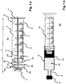
- FIG. 1 shows a piston rod 15 'according to a first embodiment of the invention.
- the piston rod 15 ′ has an essentially cruciform cross section and is formed by the two legs 3.
- Stabilizing elements 7 are attached along the longitudinal axis.
- the rear of the piston rod 15 ' is closed by a flange 4 with a larger diameter.
- the notches 5 made at the rear end enable the piston rod 15 '(as part of a syringe 20) to be operated in a syringe pump.
- the piston rod 15 ' is designed for operation in a syringe 20 with a capacity of up to about 50 ml to 70 ml.
- a scale 6 to 50 ml is indicated on the piston rod 15'.
- the piston rod 15 ' has a diameter D with 25 mm D 30 mm and / or a length L with 100 mm L 150 mm.
- the front of the piston rod 15 ' is provided by a connecting section 1, via which the piston rod 15' is connected to a piston 12 (not shown here) (see FIG Figure 1.b ).
- the connecting section 1 is provided here, for example, by a screw thread.
- Three ring elements 2a, 2b, 2c adjoin the rear of the connecting section 1. This enables haptic and / or acoustic control in particular for the user when screwing the piston rod 15 "into the piston 12.
- the ring elements 2a, 2b, 2c preferably extend completely over the circumference of the piston rod 15 '.
- the front ring element 2a also forms the stop when the piston rod 15 'is screwed into the piston 12.
- the three ring elements 2a, 2b, 2c are preferably arranged equidistant from one another. In one embodiment, the three ring elements 2a, 2b, 2c are each at a distance R of 2 mm to 8 mm.
- the ring elements 2a, 2b, 2c have, for example, a thickness of approximately 0.5 mm to approximately 5 mm, preferably approximately 1 mm to approximately 3 mm.
- the cross-shaped cross-section of the piston rod 15 ' also continues between the three ring elements 2a, 2b, 2c.
- the diameter D of the piston rod is the same or substantially the same along the longitudinal axis.
- so-called wing elements 3a, 3b or ribs are formed between the three ring elements 2a, 2b, 2c.
- the front wing elements 3a here four, connect the front ring 2a to the middle ring 2b.
- the rear wing elements 3b here four, connect the middle ring 2b to the rear ring 2b.
- the ring elements 2a, 2b, 2c and the wing elements 3a, 3b enable the piston rod 15 'to be inserted into the syringe body 8 as coaxially as possible and thereby screw the piston rod 15' into the piston as coaxial as possible 12 (see Figure 1.b ).
- An oblique application of the piston rod 15 'to the piston 12, a possible tilting of the piston 12 associated therewith and a leakage ultimately resulting therefrom can thereby be reduced or even avoided.
- FIG.b illustrates the use of the piston rod 15 ' Figure 1.a in a prefilled syringe 20.
- the syringe 20 comprises a syringe body 8 with a nozzle 9 arranged on the front side of the syringe body 8, a cap 11 closing the nozzle 9, a plunger 12 arranged in the syringe body 8, which closes the interior of the syringe body 8 in a liquid-tight manner, and the piston rod 15 ' Figure 1a which is connected to the piston 12 via its connecting section 1.
- the connection between the piston 12 and the piston rod 15 ' is provided here by a screw connection.
- a thread is also provided inside the piston 12, but this is not shown in the figure.
- the outer diameter D or D F of the piston rod 15 ′ and / or the ring elements 2a, 2b, 2c and / or the wing elements 3a, 3b can be the same as the inner diameter of the syringe body 8.
- the outer diameter D or D F of the piston rod 15' and / or the ring elements 2a, 2b, 2c and / or the wing elements 3a, 3b is smaller than the inner diameter of the syringe body 8.
- the outer diameter D or D F is preferably reduced by approximately 0.5 mm to 5 mm compared to the inner diameter of the syringe body 8.
- the pre-filled syringe 20 can, for example, be filled via its initially open rear side and then closed with the piston 12.
- the piston 12 can, however, also be introduced into the syringe body 8 with the piston rod 15 ′ already screwed into the piston 12.
- the position of the plunger 12 in the pre-filled syringe body 8 and the position of the three ring elements 2a, 2b, 2c on the plunger rod 15 ' are preferably coordinated so that in a first step, when the plunger rod 15' with its connecting section 1 on the plunger 12 is attached, the two front rings 2a, 2b are already arranged in the interior of the syringe body 8 and are preferably guided through the inside of the syringe body 8.
- the piston rod 15 ' is first by the two front ring elements 2a, 2b and the front wing elements 3a and then also by the rear wing elements 3b in the Syringe body 8 out.
- the rear third ring 2c supports the guidance of the piston rod 15 'during the final, firm connection of the piston rod 15' to the piston 12.
- the three rings 2a, 2b, 2c are in the state in which the piston rod 15 'is completely connected to the piston 12 is connected, preferably screwed into the piston 12, is positioned in the interior of the syringe body 8.
- the ring elements 2a, 2b, 2c prove to be advantageous because they prevent tilting over the entire circumference of 360 °.
- the wing elements 3a, 3b prove to be advantageous since they allow a longer guidance along the longitudinal axis of the piston rod 15 '. The present invention combines these advantages.
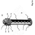
- Figure 2.a to 2.c show a piston rod 15 ′′ according to a second embodiment of the invention. Only the differences to the piston rod 15 'from FIG Figure 1.a explained. For all other components, refer to the description above Figure 1.a referenced. There is no scale on the piston rod 15 ".
- the wing elements 3a, 3b which connect the three ring elements 2a, 2b, 2c to one another, do not have the same outer diameter as the three ring elements 2a, 2b, 2c.
- the outside diameter D F of the wing elements 3a, 3b is smaller than the outside diameter D of the three ring elements 2a, 2b, 2c.
- the outer diameter D F of the wing elements 3a, 3b is preferably reduced by approximately 4 mm to 8 mm compared to the outer diameter D of the ring elements 2a, 2b, 2c. In the present case there are exactly three ring elements which are located in the front region of the piston rod 15 '.
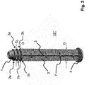
- FIG. 3 a piston rod 15 '"according to a third embodiment of the invention.
- the structure of this piston rod 15'” corresponds essentially to the structure of the piston rod 15 "from the Figure 2.a to 2.c .
- the present piston rod 15 '" only has different dimensions, since it is designed for a syringe 20 with a capacity of up to about 20 ml to 30 ml.
- the piston rod 15'" has a diameter D with 13 mm D 23 mm and / or a length L with 100 mm L 150 mm.
- the distance R between the ring elements is also here 2 mm R 8 mm.
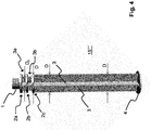
- FIG. 4 a piston rod 15 "" according to a fourth embodiment of the invention.
- the structure of this piston rod 15 “” essentially corresponds to the structure of the piston rods 15 "and 15 '" from the Figures 2.a to 2.c and 3 .
- the present piston rod 15 ′′ ′′ merely has different dimensions, since it is designed for a syringe 20 with a capacity of up to approximately 10 ml to 15 ml.
- the piston rod 15 ′′ ′′ has a diameter D with 8 mm D 18 mm and / or a length L with 80 mm L mm 110 mm.
- the distance R between the ring elements is here 2 mm R 8 mm.
- no stabilizing elements 7 are provided on the piston rod 15 ′′ ′′.
Landscapes
- Health & Medical Sciences (AREA)
- Engineering & Computer Science (AREA)
- Animal Behavior & Ethology (AREA)
- General Health & Medical Sciences (AREA)
- Biomedical Technology (AREA)
- Heart & Thoracic Surgery (AREA)
- Hematology (AREA)
- Life Sciences & Earth Sciences (AREA)
- Vascular Medicine (AREA)
- Anesthesiology (AREA)
- Public Health (AREA)
- Veterinary Medicine (AREA)
- Diabetes (AREA)
- Chemical & Material Sciences (AREA)
- Composite Materials (AREA)
- Mechanical Engineering (AREA)
- Infusion, Injection, And Reservoir Apparatuses (AREA)
Applications Claiming Priority (3)
| Application Number | Priority Date | Filing Date | Title |
|---|---|---|---|
| EP15000587 | 2015-03-02 | ||
| PCT/EP2016/054351 WO2016139215A1 (de) | 2015-03-02 | 2016-03-02 | Kolbenstange mit wenigstens drei ringelementen für eine vorgefüllte spritze |
| EP16707143.0A EP3265154B1 (de) | 2015-03-02 | 2016-03-02 | Kolbenstange mit wenigstens drei ringelementen für eine vorgefüllte spritze |
Related Parent Applications (2)
| Application Number | Title | Priority Date | Filing Date |
|---|---|---|---|
| EP16707143.0A Division EP3265154B1 (de) | 2015-03-02 | 2016-03-02 | Kolbenstange mit wenigstens drei ringelementen für eine vorgefüllte spritze |
| EP16707143.0A Division-Into EP3265154B1 (de) | 2015-03-02 | 2016-03-02 | Kolbenstange mit wenigstens drei ringelementen für eine vorgefüllte spritze |
Publications (1)
| Publication Number | Publication Date |
|---|---|
| EP3760260A1 true EP3760260A1 (de) | 2021-01-06 |
Family
ID=52596725
Family Applications (2)
| Application Number | Title | Priority Date | Filing Date |
|---|---|---|---|
| EP20186074.9A Pending EP3760260A1 (de) | 2015-03-02 | 2016-03-02 | Kolbenstange mit wenigstens drei ringelelementen für eine vorgefüllte spritze |
| EP16707143.0A Active EP3265154B1 (de) | 2015-03-02 | 2016-03-02 | Kolbenstange mit wenigstens drei ringelementen für eine vorgefüllte spritze |
Family Applications After (1)
| Application Number | Title | Priority Date | Filing Date |
|---|---|---|---|
| EP16707143.0A Active EP3265154B1 (de) | 2015-03-02 | 2016-03-02 | Kolbenstange mit wenigstens drei ringelementen für eine vorgefüllte spritze |
Country Status (10)
Families Citing this family (3)
| Publication number | Priority date | Publication date | Assignee | Title |
|---|---|---|---|---|
| CN107427642B (zh) * | 2015-03-02 | 2021-04-02 | 费森尤斯卡比奥地利有限公司 | 用于预充填的注射器的带有至少三个环形元件的活塞杆 |
| EP4138958A1 (de) * | 2020-04-24 | 2023-03-01 | Fresenius Kabi Deutschland GmbH | Spritze, spritzenkörper sowie verfahren zu dessen herstellung |
| EP4190377A4 (en) * | 2020-08-20 | 2024-01-03 | TERUMO Kabushiki Kaisha | PREFILLED SYRINGE |
Citations (7)
| Publication number | Priority date | Publication date | Assignee | Title |
|---|---|---|---|---|
| WO2001097885A1 (fr) * | 2000-06-19 | 2001-12-27 | Terumo Kabushiki Kaisha | Seringue |
| JP2002272843A (ja) * | 2001-03-15 | 2002-09-24 | Terumo Corp | シリンジ |
| WO2010139793A1 (en) * | 2009-06-04 | 2010-12-09 | Novo Nordisk A/S | Mixing device with piston coupling arrangement |
| JP2011072394A (ja) * | 2009-09-29 | 2011-04-14 | Terumo Corp | 注射器およびプレフィルドシリンジ |
| EP2484393A1 (en) * | 2009-09-30 | 2012-08-08 | Terumo Kabushiki Kaisha | Pre-filled syringe |
| WO2014053560A1 (de) | 2012-10-04 | 2014-04-10 | Fresenius Kabi Deutschland Gmbh | Applikationsanordnung mit einem arzneistofffluid |
| WO2014122782A1 (ja) * | 2013-02-08 | 2014-08-14 | テルモ株式会社 | プレフィルドシリンジ |
Family Cites Families (17)
| Publication number | Priority date | Publication date | Assignee | Title |
|---|---|---|---|---|
| AUPN615095A0 (en) * | 1995-10-24 | 1995-11-16 | Astra Pharmaceuticals Pty Ltd | Tamper evident syringe design |
| JPH10277153A (ja) * | 1997-04-04 | 1998-10-20 | Asahi Chem Ind Co Ltd | 薬液入り注入器具 |
| ATE307629T1 (de) * | 1999-07-15 | 2005-11-15 | Bracco Int Bv | Kolben für spritze |
| JP2001314506A (ja) * | 2000-05-02 | 2001-11-13 | Daiichi Radioisotope Labs Ltd | 注射筒用プランジャーロッド |
| JP2005508231A (ja) | 2001-11-02 | 2005-03-31 | メリディアン メディカル テクノロジーズ,インコーポレイテッド | 薬剤容器、薬剤を投与するための投薬キット、および投薬キットの包装方法 |
| EP1624906A1 (en) * | 2003-05-19 | 2006-02-15 | Tjaart Andries Du Plessis | Preparation of an osteoinductive agent |
| WO2006087762A1 (ja) * | 2005-02-15 | 2006-08-24 | Kabushiki Kaisha Top | シリンジ |
| CN2897287Y (zh) * | 2006-04-19 | 2007-05-09 | 山东威高集团医用高分子制品股份有限公司 | 一种低阻力注射器 |
| EP1923085A1 (en) * | 2006-11-17 | 2008-05-21 | Sanofi-Aventis Deutschland GmbH | Dosing and drive mechanism for drug delivery device |
| PL2020245T3 (pl) * | 2007-07-31 | 2012-04-30 | Al Chi Mi A S R L | Sposoby wykonania urządzenia do zabiegów okulistycznych |
| JP5428157B2 (ja) * | 2007-12-27 | 2014-02-26 | 大日本印刷株式会社 | プレフィルドシリンジ用の包装袋 |
| JP2010246842A (ja) * | 2009-04-20 | 2010-11-04 | Usui Seisakusho:Kk | シリンジ |
| EP2554204B1 (en) * | 2010-03-29 | 2017-11-08 | Terumo Kabushiki Kaisha | Prefilled syringe |
| US9433729B2 (en) * | 2010-09-14 | 2016-09-06 | Neomed, Inc. | Enteral syringe |
| DK2627382T3 (en) * | 2010-10-11 | 2016-07-25 | Shl Group Ab | Drug delivery devices |
| CN107206177B (zh) * | 2014-12-12 | 2021-06-25 | 维克森林大学健康科学 | 增量式注射器 |
| CN107427642B (zh) * | 2015-03-02 | 2021-04-02 | 费森尤斯卡比奥地利有限公司 | 用于预充填的注射器的带有至少三个环形元件的活塞杆 |
-
2016
- 2016-03-02 CN CN201680013197.XA patent/CN107427642B/zh active Active
- 2016-03-02 AU AU2016227737A patent/AU2016227737B2/en active Active
- 2016-03-02 DE DE202016008940.5U patent/DE202016008940U1/de active Active
- 2016-03-02 JP JP2017546064A patent/JP6872490B2/ja active Active
- 2016-03-02 US US15/555,220 patent/US10543319B2/en active Active
- 2016-03-02 EP EP20186074.9A patent/EP3760260A1/de active Pending
- 2016-03-02 BR BR112017017822-2A patent/BR112017017822B1/pt active IP Right Grant
- 2016-03-02 CA CA2978090A patent/CA2978090C/en active Active
- 2016-03-02 ES ES16707143T patent/ES2833369T3/es active Active
- 2016-03-02 WO PCT/EP2016/054351 patent/WO2016139215A1/de active Application Filing
- 2016-03-02 EP EP16707143.0A patent/EP3265154B1/de active Active
-
2020
- 2020-01-27 US US16/752,784 patent/US11571520B2/en active Active
Patent Citations (7)
| Publication number | Priority date | Publication date | Assignee | Title |
|---|---|---|---|---|
| WO2001097885A1 (fr) * | 2000-06-19 | 2001-12-27 | Terumo Kabushiki Kaisha | Seringue |
| JP2002272843A (ja) * | 2001-03-15 | 2002-09-24 | Terumo Corp | シリンジ |
| WO2010139793A1 (en) * | 2009-06-04 | 2010-12-09 | Novo Nordisk A/S | Mixing device with piston coupling arrangement |
| JP2011072394A (ja) * | 2009-09-29 | 2011-04-14 | Terumo Corp | 注射器およびプレフィルドシリンジ |
| EP2484393A1 (en) * | 2009-09-30 | 2012-08-08 | Terumo Kabushiki Kaisha | Pre-filled syringe |
| WO2014053560A1 (de) | 2012-10-04 | 2014-04-10 | Fresenius Kabi Deutschland Gmbh | Applikationsanordnung mit einem arzneistofffluid |
| WO2014122782A1 (ja) * | 2013-02-08 | 2014-08-14 | テルモ株式会社 | プレフィルドシリンジ |
Also Published As
| Publication number | Publication date |
|---|---|
| CN107427642A (zh) | 2017-12-01 |
| US20200155765A1 (en) | 2020-05-21 |
| AU2016227737A1 (en) | 2017-09-07 |
| US10543319B2 (en) | 2020-01-28 |
| BR112017017822B1 (pt) | 2023-02-07 |
| US20180050158A1 (en) | 2018-02-22 |
| HK1245684A1 (zh) | 2018-08-31 |
| JP2018510688A (ja) | 2018-04-19 |
| JP6872490B2 (ja) | 2021-05-19 |
| WO2016139215A1 (de) | 2016-09-09 |
| AU2016227737B2 (en) | 2020-07-23 |
| CA2978090C (en) | 2023-12-12 |
| US11571520B2 (en) | 2023-02-07 |
| DE202016008940U1 (de) | 2020-11-30 |
| CN107427642B (zh) | 2021-04-02 |
| BR112017017822A2 (pt) | 2018-04-10 |
| EP3265154B1 (de) | 2020-11-18 |
| ES2833369T3 (es) | 2021-06-15 |
| CA2978090A1 (en) | 2016-09-09 |
| EP3265154A1 (de) | 2018-01-10 |
Similar Documents
| Publication | Publication Date | Title |
|---|---|---|
| DE3885018T2 (de) | Injektionsspritze. | |
| DE69726531T2 (de) | Verriegelbare Schutzhülse für vorgefüllte Spritze | |
| DE69724349T2 (de) | Kolben für Spritze | |
| DE60021275T2 (de) | Mehrfachdosierungspritze | |
| DE10009814B4 (de) | Einweg-Injektorkappe | |
| DE602004003549T2 (de) | Sicherheitsnadel | |
| DE69725220T2 (de) | Kolbenvorrichtung mit Beipass zum Gebrauch im Zylinder einer Mehrkammerspritze | |
| EP2300081B1 (de) | Ampulle mit ampullenhalterung | |
| DE2744439C2 (de) | Einweg-Injektionsspritze | |
| CH696186A5 (de) | Vorrichtung zur Sicherung von Injektionsnadeln. | |
| DE3844150A1 (de) | Injektionsspritze zur einmaligen verwendung | |
| DE2909002B2 (de) | Injektionsspritze für einmalige Verwendung | |
| DE69603597T2 (de) | Vorgefüllte sicherheitsspritze | |
| WO2011097742A1 (de) | Austragvorrichtung mit rastelement | |
| EP3265154B1 (de) | Kolbenstange mit wenigstens drei ringelementen für eine vorgefüllte spritze | |
| DE2259825A1 (de) | Injektionsspritze | |
| EP1417981B1 (de) | Medizinische Spritze | |
| EP0498376A1 (de) | Selbstzerstörende Einweg-Sicherheitsspritze | |
| DE202007011833U1 (de) | Sicherheitsinjektionsspritze | |
| DE69132034T2 (de) | Sicherheitseinrichtung für spritze mit radial deformierbarem körper | |
| CH397157A (de) | Injektionsspritze | |
| EP4169547B1 (de) | Verbesserte verabreichungsvorrichtung | |
| HK1245684B (en) | Plunger rod comprising at least three annular elements for a prefilled syringe | |
| EP4088765A1 (de) | Einweg-injektionsvorrichtung | |
| DE102017220641A1 (de) | Medikamentenbehälter |
Legal Events
| Date | Code | Title | Description |
|---|---|---|---|
| PUAI | Public reference made under article 153(3) epc to a published international application that has entered the european phase |
Free format text: ORIGINAL CODE: 0009012 |
|
| STAA | Information on the status of an ep patent application or granted ep patent |
Free format text: STATUS: THE APPLICATION HAS BEEN PUBLISHED |
|
| AC | Divisional application: reference to earlier application |
Ref document number: 3265154 Country of ref document: EP Kind code of ref document: P |
|
| AK | Designated contracting states |
Kind code of ref document: A1 Designated state(s): AL AT BE BG CH CY CZ DE DK EE ES FI FR GB GR HR HU IE IS IT LI LT LU LV MC MK MT NL NO PL PT RO RS SE SI SK SM TR |
|
| STAA | Information on the status of an ep patent application or granted ep patent |
Free format text: STATUS: REQUEST FOR EXAMINATION WAS MADE |
|
| 17P | Request for examination filed |
Effective date: 20210617 |
|
| RBV | Designated contracting states (corrected) |
Designated state(s): AL AT BE BG CH CY CZ DE DK EE ES FI FR GB GR HR HU IE IS IT LI LT LU LV MC MK MT NL NO PL PT RO RS SE SI SK SM TR |
|
| STAA | Information on the status of an ep patent application or granted ep patent |
Free format text: STATUS: EXAMINATION IS IN PROGRESS |
|
| 17Q | First examination report despatched |
Effective date: 20240419 |