EP3265154B1 - Kolbenstange mit wenigstens drei ringelementen für eine vorgefüllte spritze - Google Patents
Kolbenstange mit wenigstens drei ringelementen für eine vorgefüllte spritze Download PDFInfo
- Publication number
- EP3265154B1 EP3265154B1 EP16707143.0A EP16707143A EP3265154B1 EP 3265154 B1 EP3265154 B1 EP 3265154B1 EP 16707143 A EP16707143 A EP 16707143A EP 3265154 B1 EP3265154 B1 EP 3265154B1
- Authority
- EP
- European Patent Office
- Prior art keywords
- plunger
- plunger rod
- syringe body
- syringe
- ring elements
- Prior art date
- Legal status (The legal status is an assumption and is not a legal conclusion. Google has not performed a legal analysis and makes no representation as to the accuracy of the status listed.)
- Active
Links
- 229940071643 prefilled syringe Drugs 0.000 title claims description 21
- 239000012530 fluid Substances 0.000 claims description 3
- 239000007788 liquid Substances 0.000 description 13
- 239000004033 plastic Substances 0.000 description 5
- OLBCVFGFOZPWHH-UHFFFAOYSA-N propofol Chemical compound CC(C)C1=CC=CC(C(C)C)=C1O OLBCVFGFOZPWHH-UHFFFAOYSA-N 0.000 description 5
- 229920000089 Cyclic olefin copolymer Polymers 0.000 description 4
- 229920000642 polymer Polymers 0.000 description 4
- 229960004134 propofol Drugs 0.000 description 4
- 239000013078 crystal Substances 0.000 description 2
- 150000001925 cycloalkenes Chemical class 0.000 description 2
- 239000000839 emulsion Substances 0.000 description 2
- 238000004806 packaging method and process Methods 0.000 description 2
- 239000002904 solvent Substances 0.000 description 2
- 230000000087 stabilizing effect Effects 0.000 description 2
- 230000007704 transition Effects 0.000 description 2
- 239000004743 Polypropylene Substances 0.000 description 1
- 239000004480 active ingredient Substances 0.000 description 1
- QVGXLLKOCUKJST-UHFFFAOYSA-N atomic oxygen Chemical compound [O] QVGXLLKOCUKJST-UHFFFAOYSA-N 0.000 description 1
- 230000001419 dependent effect Effects 0.000 description 1
- 229940079593 drug Drugs 0.000 description 1
- 239000003814 drug Substances 0.000 description 1
- 238000001802 infusion Methods 0.000 description 1
- 238000003780 insertion Methods 0.000 description 1
- 230000037431 insertion Effects 0.000 description 1
- 239000000314 lubricant Substances 0.000 description 1
- 229910052760 oxygen Inorganic materials 0.000 description 1
- 239000001301 oxygen Substances 0.000 description 1
- 235000016236 parenteral nutrition Nutrition 0.000 description 1
- -1 polypropylene Polymers 0.000 description 1
- 229920001155 polypropylene Polymers 0.000 description 1
- 239000000126 substance Substances 0.000 description 1
Images


Classifications
-
- A—HUMAN NECESSITIES
- A61—MEDICAL OR VETERINARY SCIENCE; HYGIENE
- A61M—DEVICES FOR INTRODUCING MEDIA INTO, OR ONTO, THE BODY; DEVICES FOR TRANSDUCING BODY MEDIA OR FOR TAKING MEDIA FROM THE BODY; DEVICES FOR PRODUCING OR ENDING SLEEP OR STUPOR
- A61M5/00—Devices for bringing media into the body in a subcutaneous, intra-vascular or intramuscular way; Accessories therefor, e.g. filling or cleaning devices, arm-rests
- A61M5/178—Syringes
- A61M5/31—Details
- A61M5/315—Pistons; Piston-rods; Guiding, blocking or restricting the movement of the rod or piston; Appliances on the rod for facilitating dosing ; Dosing mechanisms
- A61M5/31511—Piston or piston-rod constructions, e.g. connection of piston with piston-rod
- A61M5/31515—Connection of piston with piston rod
-
- A—HUMAN NECESSITIES
- A61—MEDICAL OR VETERINARY SCIENCE; HYGIENE
- A61M—DEVICES FOR INTRODUCING MEDIA INTO, OR ONTO, THE BODY; DEVICES FOR TRANSDUCING BODY MEDIA OR FOR TAKING MEDIA FROM THE BODY; DEVICES FOR PRODUCING OR ENDING SLEEP OR STUPOR
- A61M5/00—Devices for bringing media into the body in a subcutaneous, intra-vascular or intramuscular way; Accessories therefor, e.g. filling or cleaning devices, arm-rests
- A61M5/002—Packages specially adapted therefor, e.g. for syringes or needles, kits for diabetics
-
- A—HUMAN NECESSITIES
- A61—MEDICAL OR VETERINARY SCIENCE; HYGIENE
- A61M—DEVICES FOR INTRODUCING MEDIA INTO, OR ONTO, THE BODY; DEVICES FOR TRANSDUCING BODY MEDIA OR FOR TAKING MEDIA FROM THE BODY; DEVICES FOR PRODUCING OR ENDING SLEEP OR STUPOR
- A61M5/00—Devices for bringing media into the body in a subcutaneous, intra-vascular or intramuscular way; Accessories therefor, e.g. filling or cleaning devices, arm-rests
- A61M5/178—Syringes
- A61M5/28—Syringe ampoules or carpules, i.e. ampoules or carpules provided with a needle
-
- A—HUMAN NECESSITIES
- A61—MEDICAL OR VETERINARY SCIENCE; HYGIENE
- A61M—DEVICES FOR INTRODUCING MEDIA INTO, OR ONTO, THE BODY; DEVICES FOR TRANSDUCING BODY MEDIA OR FOR TAKING MEDIA FROM THE BODY; DEVICES FOR PRODUCING OR ENDING SLEEP OR STUPOR
- A61M5/00—Devices for bringing media into the body in a subcutaneous, intra-vascular or intramuscular way; Accessories therefor, e.g. filling or cleaning devices, arm-rests
- A61M5/178—Syringes
- A61M5/31—Details
- A61M5/315—Pistons; Piston-rods; Guiding, blocking or restricting the movement of the rod or piston; Appliances on the rod for facilitating dosing ; Dosing mechanisms
- A61M5/31511—Piston or piston-rod constructions, e.g. connection of piston with piston-rod
-
- B—PERFORMING OPERATIONS; TRANSPORTING
- B65—CONVEYING; PACKING; STORING; HANDLING THIN OR FILAMENTARY MATERIAL
- B65D—CONTAINERS FOR STORAGE OR TRANSPORT OF ARTICLES OR MATERIALS, e.g. BAGS, BARRELS, BOTTLES, BOXES, CANS, CARTONS, CRATES, DRUMS, JARS, TANKS, HOPPERS, FORWARDING CONTAINERS; ACCESSORIES, CLOSURES, OR FITTINGS THEREFOR; PACKAGING ELEMENTS; PACKAGES
- B65D75/00—Packages comprising articles or materials partially or wholly enclosed in strips, sheets, blanks, tubes, or webs of flexible sheet material, e.g. in folded wrappers
- B65D75/28—Articles or materials wholly enclosed in composite wrappers, i.e. wrappers formed by associating or interconnecting two or more sheets or blanks
- B65D75/30—Articles or materials enclosed between two opposed sheets or blanks having their margins united, e.g. by pressure-sensitive adhesive, crimping, heat-sealing, or welding
- B65D75/32—Articles or materials enclosed between two opposed sheets or blanks having their margins united, e.g. by pressure-sensitive adhesive, crimping, heat-sealing, or welding one or both sheets or blanks being recessed to accommodate contents
- B65D75/36—Articles or materials enclosed between two opposed sheets or blanks having their margins united, e.g. by pressure-sensitive adhesive, crimping, heat-sealing, or welding one or both sheets or blanks being recessed to accommodate contents one sheet or blank being recessed and the other formed of relatively stiff flat sheet material, e.g. blister packages, the recess or recesses being preformed
- B65D75/366—Articles or materials enclosed between two opposed sheets or blanks having their margins united, e.g. by pressure-sensitive adhesive, crimping, heat-sealing, or welding one or both sheets or blanks being recessed to accommodate contents one sheet or blank being recessed and the other formed of relatively stiff flat sheet material, e.g. blister packages, the recess or recesses being preformed and forming one compartment
-
- A—HUMAN NECESSITIES
- A61—MEDICAL OR VETERINARY SCIENCE; HYGIENE
- A61M—DEVICES FOR INTRODUCING MEDIA INTO, OR ONTO, THE BODY; DEVICES FOR TRANSDUCING BODY MEDIA OR FOR TAKING MEDIA FROM THE BODY; DEVICES FOR PRODUCING OR ENDING SLEEP OR STUPOR
- A61M5/00—Devices for bringing media into the body in a subcutaneous, intra-vascular or intramuscular way; Accessories therefor, e.g. filling or cleaning devices, arm-rests
- A61M5/178—Syringes
- A61M5/31—Details
- A61M2005/3125—Details specific display means, e.g. to indicate dose setting
- A61M2005/3126—Specific display means related to dosing
-
- A—HUMAN NECESSITIES
- A61—MEDICAL OR VETERINARY SCIENCE; HYGIENE
- A61M—DEVICES FOR INTRODUCING MEDIA INTO, OR ONTO, THE BODY; DEVICES FOR TRANSDUCING BODY MEDIA OR FOR TAKING MEDIA FROM THE BODY; DEVICES FOR PRODUCING OR ENDING SLEEP OR STUPOR
- A61M2205/00—General characteristics of the apparatus
- A61M2205/58—Means for facilitating use, e.g. by people with impaired vision
- A61M2205/581—Means for facilitating use, e.g. by people with impaired vision by audible feedback
Definitions
- the invention relates to a plunger rod for a syringe body pre-filled with a medical liquid and a syringe comprising the plunger rod and the syringe body pre-filled with the medical liquid.
- a syringe pre-filled with a medical liquid is known.
- the piston rod and the tip body are stored next to one another in an overpack.
- the piston rod and the syringe body are first removed from the outer packaging. Then the plunger rod is screwed into the plunger that closes the back of the syringe body.
- the WO 2010/139793 A1 discloses a pre-filled two-chamber syringe having a rear piston into which a piston rod can be inserted. To connect the piston rod to the rear piston, the piston rod has circumferential teeth at the end which is brought into engagement with the rear piston.
- the piston rod has ring elements at its proximal end which are connected by wing elements.
- WO01 / 97885 , JP2011072394 , and JP2002272843 discloses a syringe having a plunger rod with two ring members.
- the invention is based on the object of providing an improved piston rod.
- the insertion, in particular the screwing, of the piston rod into the piston is to be improved.
- leakage by tilting the piston should as far as possible be avoided.
- the guidance of the plunger rod in the syringe body is to be improved, especially when the syringe is used in a syringe pump.
- the pre-filled syringe comprises the following components: a syringe body filled with a medical liquid, which has a nozzle on a front side which is closed with a cap and which is closed on a rear side with a displaceable plunger, and one via the rear side in the syringe body insertable plunger rod which has a connecting section on a front side via which the plunger rod can be connected to the plunger, with at least three ring elements, which extend at least in sections around a longitudinal axis of the plunger rod, being arranged on the plunger rod on a rear side of the connecting section that, when the plunger rod is completely connected to the plunger, they are in the syringe body, wherein an outer diameter (D) of the three ring elements is equal to an inner diameter of the syringe body or is slightly smaller than an inner diameter of the syringe body, with between Chen the ring elements are arranged over the circumference of the piston rod distributed wing elements which extend radially
- the three ring elements support a coaxial connection of the piston rod with the piston.
- the ring elements prove to be advantageous because they prevent tilting over the entire circumference of 360 °.
- the three ring elements enable the user to haptic and / or acoustic control when connecting the piston rod to the piston. For example, if the user connects the piston rod properly and straight to the piston, he does not receive any haptic and / or acoustic feedback.
- the user inadvertently tries to connect the plunger rod to the plunger incorrectly at an angle, he can especially perceive the transition of the plunger rod from the middle ring element to the rear ring element at the edge of the rear syringe body opening as a kind of jump, preferably connected with a kind of click .
- This enables the user to recognize that he is trying to improperly connect the piston rod to the piston and then correct the position of the piston rod accordingly.
- the position of the plunger in the prefilled syringe body and the position of the three ring elements on the plunger rod are preferably coordinated so that in a first step, when the connecting section of the plunger rod is attached to the plunger, the two front rings are already inside the syringe body are arranged.
- the piston rod is first guided through the two front ring elements.
- the third ring supports the guidance of the piston rod during the final, firm connection of the piston rod to the piston.
- the three ring elements are positioned in the interior of the syringe body in the state in which the piston rod is completely connected to the piston, preferably screwed into the piston.
- an outer diameter of the three ring elements is equal to an inner diameter of the syringe body or somewhat smaller than an inner diameter of the syringe body.
- wing elements Between the ring elements there are arranged wing elements or ribs which are distributed over the circumference of the piston rods and which extend radially outward.
- the wing elements preferably connect the ring elements to one another.
- the wing elements prove to be advantageous because they allow a longer, continuous guidance in sections along the longitudinal axis of the piston rod.
- At least four wing elements are arranged between the ring elements, preferably at an angle of 90 ° to one another. This is intended to support the most coaxial guidance of the piston rod.
- the wing elements preferably have an outer diameter which is equal to the inner diameter of the syringe body or is somewhat smaller than the inner diameter of the syringe body.
- the wing elements have an outer diameter which is smaller than an outer diameter of the ring elements. This improves the haptic and / or acoustic control when the piston rod is connected to the piston and / or when the piston rod is inserted into the syringe body.
- the outer diameter of the wing elements is reduced by 1 mm to 10 mm, preferably by 4 mm to 8 mm, compared to the outer diameter of the ring elements.
- the prefilled syringe can be provided in an overpack. If, for example, the medical liquid is sensitive to oxygen and the syringe body is not sufficiently oxygen-impermeable, the syringe can be packed in an oxygen-impermeable overpack, for example in a blister.
- the piston rod can, for example, already be preassembled on the piston. But it can also not be pre-assembled next to the syringe body in the outer packaging. Therefore, the scope of the invention also includes an overpack with an interior space in which the above-described syringe according to the invention is enclosed.
- the piston rod comprises a front-side connecting section via which the piston rod can be connected to a piston.
- at least three ring elements are arranged on a rear side of the connecting section, which ring elements extend at least in sections around a longitudinal axis of the piston rod.
- the three ring elements are, preferably in each case, arranged at a distance R from one another with 0.5 mm R mm 20 mm, preferably 1 mm R 10 mm, particularly preferably 2 mm R 8 mm.
- the ring elements have, for example, a thickness of about 0.5 mm to about 5 mm, preferably from about 1 mm to about 3 mm.
- the piston rod has a diameter D with 8 mm ⁇ D ⁇ 30 mm and / or a length L with 80 mm ⁇ L ⁇ 150 mm.
- a syringe comprising a syringe body, a plunger and the plunger rod described above, wherein the plunger can be positioned in the syringe body and the three ring elements are arranged on the plunger rod that they are when the plunger rod is completely Plunger is connected, located in the syringe body.
- the syringe body is preferably prefilled with a medical liquid.
- the pre-filled syringe can, for example, have a capacity of 5 ml to 100 ml.
- the medical liquid can be or comprise, for example, a liquid for enteral and / or parenteral nutrition and / or for infusion.
- the medical fluid can be provided by a solution and / or by an emulsion.
- the medicinal liquid can also contain medicinal active ingredients.
- the medical liquid is or comprises the drug fluid propofol, in particular a propofol emulsion. Propofol is described by the chemical name 2,6-diisopropylphenol (IUAPC).
- the syringe body can be molded from plastic, which comprises one of the following polymers: cyclo-olefin copolymer, cyclo-olefin polymer or crystal clear polymer.
- plastic which comprises one of the following polymers: cyclo-olefin copolymer, cyclo-olefin polymer or crystal clear polymer.
- a plastic container is resistant to solvents.
- such a plastic container can be used to store propofol, which acts as a solvent.
- the outside of the plunger and / or the inside of the syringe body are preferably covered, at least in sections, with a lubricant, preferably siliconized.
- the plastic piston rod is molded from plastic, which preferably comprises one of the following polymers: cyclo-olefin copolymer, cyclo-olefin polymer or crystal clear polymer, or it is molded from polypropylene.
- FIG. 1 shows a piston rod 15 'according to an embodiment.
- the piston rod 15 ′ has an essentially cruciform cross section and is formed by the two legs 3.
- Stabilizing elements 7 are attached along the longitudinal axis.
- the rear of the piston rod 15 ' is closed by a flange 4 with a larger diameter.
- the notches 5 made at the rear end enable the piston rod 15 '(as part of a syringe 20) to be operated in a syringe pump.
- the piston rod 15 ' is designed for operation in a syringe 20 with a capacity of up to about 50 ml to 70 ml.
- a scale 6 to 50 ml is indicated on the piston rod 15'.
- the piston rod 15 ' has a diameter D with 25 mm D 30 mm and / or a length L with 100 mm L 150 mm.
- the front of the piston rod 15 ' is provided by a connecting section 1, via which the piston rod 15' is connected to a piston 12 (not shown here) (see FIG Figure 1.b ).
- the connecting section 1 is provided here, for example, by a screw thread.
- Three ring elements 2a, 2b, 2c adjoin the rear of the connecting section 1. This enables haptic and / or acoustic control in particular for the user when screwing the piston rod 15 "into the piston 12.
- the ring elements 2a, 2b, 2c preferably extend completely over the circumference of the piston rod 15 '.
- the front ring element 2a also forms the stop when the piston rod 15 'is screwed into the piston 12.
- the three ring elements 2a, 2b, 2c are preferably arranged equidistant from one another. In one embodiment, the three ring elements 2a, 2b, 2c are each at a distance R of 2 mm to 8 mm.
- the ring elements 2a, 2b, 2c have, for example, a thickness of approximately 0.5 mm to approximately 5 mm, preferably approximately 1 mm to approximately 3 mm.
- the cross-shaped cross-section of the piston rod 15 ' also continues between the three ring elements 2a, 2b, 2c.
- the diameter D of the piston rod is the same or substantially the same along the longitudinal axis.
- so-called wing elements 3a, 3b or ribs are formed between the three ring elements 2a, 2b, 2c.
- the front wing elements 3a here four, connect the front ring 2a to the middle ring 2b.
- the rear, here four, wing elements 3b connect the middle ring 2b the rear ring 2b.
- the ring elements 2a, 2b, 2c and the wing elements 3a, 3b allow the plunger rod 15 'to be inserted into the syringe body 8 as coaxially as possible and thereby screw the plunger rod 15' into the plunger 12 as coaxially as possible (see FIG Figure 1.b ).
- An oblique application of the piston rod 15 'to the piston 12, a possible tilting of the piston 12 associated therewith and a leakage ultimately resulting therefrom can thereby be reduced or even avoided.
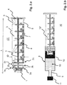
- FIG.b illustrates the use of the piston rod 15 ' Figure 1.a in a prefilled syringe 20.
- the syringe 20 comprises a syringe body 8 with a nozzle 9 arranged on the front side of the syringe body 8, a cap 11 closing the nozzle 9, a plunger 12 arranged in the syringe body 8, which closes the interior of the syringe body 8 in a liquid-tight manner, and the piston rod 15 ' Figure 1a which is connected to the piston 12 via its connecting section 1.
- the connection between the piston 12 and the piston rod 15 ' is provided here by a screw connection.
- a thread is also provided in the interior of the piston 12, but this is not shown in the figure.
- the outer diameter D or D F of the piston rod 15 ′ and / or the ring elements 2a, 2b, 2c and / or the wing elements 3a, 3b can be the same as the inner diameter of the syringe body 8.
- the outer diameter D or D F of the piston rod 15' and / or the ring elements 2a, 2b, 2c and / or the wing elements 3a, 3b is smaller than the inner diameter of the syringe body 8.
- the outer diameter D or D F is preferably reduced by approximately 0.5 mm to 5 mm compared to the inner diameter of the syringe body 8.
- the pre-filled syringe 20 can, for example, be filled via its initially open rear side and then closed with the piston 12.
- the piston 12 can, however, also be introduced into the syringe body 8 with the piston rod 15 ′ already screwed into the piston 12.
- the position of the plunger 12 in the pre-filled syringe body 8 and the position of the three ring elements 2a, 2b, 2c on the plunger rod 15 ' are preferably coordinated so that in a first step, when the plunger rod 15' with its connecting section 1 on the plunger 12 is attached, the two front rings 2a, 2b already arranged in the interior of the syringe body 8 and preferably by the Inside of the syringe body 8 are guided.
- the piston rod 15 ′ is first guided through the two front ring elements 2a, 2b and the front wing elements 3a and then also through the rear wing elements 3b in the syringe body 8.
- the rear third ring 2c supports the guidance of the piston rod 15 'during the final, firm connection of the piston rod 15' to the piston 12.
- the three rings 2a, 2b, 2c are in the state in which the piston rod 15 'is completely connected to the piston 12 is connected, preferably screwed into the piston 12, is positioned in the interior of the syringe body 8.
- the ring elements 2a, 2b, 2c prove to be advantageous because they prevent tilting over the entire circumference of 360 °.
- the wing elements 3a, 3b prove to be advantageous since they allow a longer guidance along the longitudinal axis of the piston rod 15 '. The present invention combines these advantages.
- Figure 2.a to 2.c show a piston rod 15 "according to an embodiment of the invention. Only the differences to the piston rod 15 'from FIG Figure 1.a explained. For all other components, refer to the description above Figure 1.a referenced. There is no scale on the piston rod 15 ".
- the wing elements 3a, 3b which connect the three ring elements 2a, 2b, 2c to one another, do not have the same outer diameter as the three ring elements 2a, 2b, 2c.
- the outside diameter D F of the wing elements 3a, 3b is smaller than the outside diameter D of the three ring elements 2a, 2b, 2c.
- the outer diameter D F of the wing elements 3a, 3b is preferably reduced by approximately 4 mm to 8 mm compared to the outer diameter D of the ring elements 2a, 2b, 2c. In the present case there are exactly three ring elements which are located in the front region of the piston rod 15 '.
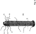
- FIG. 3 a piston rod 15 '"according to a second embodiment of the invention.
- the structure of this piston rod 15'” corresponds essentially to the structure of the piston rod 15 "from the Figure 2.a to 2.c .
- the present piston rod 15 '" only has different dimensions, since it is designed for a syringe 20 with a capacity of up to about 20 ml to 30 ml.
- the piston rod 15'" has a diameter D with 13 mm D 23 mm and / or a length L with 100 mm L 150 mm.
- the distance R between the ring elements is also here 2 mm R 8 mm.
- FIG 4 a piston rod 15 "" according to a third embodiment of the invention.
- the structure of this piston rod 15 “” essentially corresponds to the structure of the piston rods 15 "and 15 '" from the Figures 2.a to 2.c and 3 .
- the present piston rod 15 ′′ ′′ merely has different dimensions, since it is designed for a syringe 20 with a capacity of up to approximately 10 ml to 15 ml.
- the piston rod 15 "” has a diameter D with 8 mm D 18 mm and / or a length L with 80 mm L 110 mm.
- the distance R between the ring elements is here 2 mm R 8 mm.
- no stabilizing elements 7 are provided on the piston rod 15 ′′ ′′.
Landscapes
- Health & Medical Sciences (AREA)
- Engineering & Computer Science (AREA)
- Animal Behavior & Ethology (AREA)
- General Health & Medical Sciences (AREA)
- Biomedical Technology (AREA)
- Heart & Thoracic Surgery (AREA)
- Hematology (AREA)
- Life Sciences & Earth Sciences (AREA)
- Vascular Medicine (AREA)
- Anesthesiology (AREA)
- Public Health (AREA)
- Veterinary Medicine (AREA)
- Diabetes (AREA)
- Chemical & Material Sciences (AREA)
- Composite Materials (AREA)
- Mechanical Engineering (AREA)
- Infusion, Injection, And Reservoir Apparatuses (AREA)
Description
- Die Erfindung betrifft eine Kolbenstange für einen mit einer medizinischen Flüssigkeit vorgefüllten Spritzenkörper sowie eine Spritze umfassend die Kolbenstange und den mit der medizinischen Flüssigkeit vorgefüllten Spritzenkörper.
- Aus der
WO 2014/053560 A1 ist eine mit einer medizinischen Flüssigkeit vorgefüllte Spritze bekannt. Die Kolbenstange und der Spitzenkörper sind in einer Ausführungsform nebeneinander liegend in einer Überverpackung gelagert. Zur Anwendung der Spritze werden zunächst die Kolbenstange und der Spritzenkörper aus der Überverpackung entnommen. Dann wird die Kolbenstange in den die Rückseite des Spritzenkörpers verschließenden Kolben eingeschraubt. Der Inhalt der genannten Patentanmeldung wird vollumfänglich in die vorliegende Patentanmeldung durch Bezugnahme inkorporiert. - Die
WO 2010/139793 A1 offenbart eine vorgefüllte zwei-Kammernspritze, aufweisend einen hinteren Kolben in den einen Kolbenstange einführbar ist. Zur Verbindung der Kolbenstange mit dem hinteren Kolben weißt die Kolbenstange an dem Ende, welches in Eingriff mit dem hinteren Kolben gebracht wird, umlaufende Verzahnungen auf. - Aus der
WO 2014/122782 A1 ist eine mit einer medizinischen Flüssigkeit vorgefüllte Spritze bekannt. Die Kolbenstange weist in einer Ausführungsform an ihrem proximalen Ende Ringelemente auf, die durch Flügelelemente verbunden sind. -
WO01/97885 JP2011072394 JP2002272843 - Der Erfindung liegt die Aufgabe zugrunde, eine verbesserte Kolbenstange bereitzustellen. Das Einsetzen, insbesondere das Einschrauben, der Kolbenstange in den Kolben soll verbessert werden. Insbesondere soll eine Leckage durch ein Verkippen des Kolbens möglichst vermieden werden. Ferner soll die Führung der Kolbenstange in dem Spritzenkörper verbessert werden, insbesondere bei der Verwendung der Spritze in einer Spritzenpumpe. Diese Aufgabe wird durch Gegenstände mit den Merkmalen nach den unabhängigen Ansprüchen gelöst. Vorteilhafte Ausführungsformen sind Gegenstand der abhängigen Ansprüche, der Beschreibung sowie der Zeichnungen.
- Die erfindungsgemäße vorgefüllte Spritze umfasst die folgenden Bestandteile: einen mit einer medizinischen Flüssigkeit befüllten Spritzenkörper, der an einer Vorderseite eine Düse aufweist, die mit einer Kappe verschlossen ist, und der an einer Rückseite mit einem verschiebbaren Kolben verschlossen ist, und eine über die Rückseite in den Spritzenkörper einführbare Kolbenstange, die an einer Vorderseite einen Verbindungsabschnitt aufweist, über den die Kolbenstange mit dem Kolben verbindbar ist, wobei an einer Rückseite des Verbindungsabschnitts wenigstens drei Ringelemente, die sich zumindest abschnittweise um eine Längsachse der Kolbenstange erstrecken, so an der Kolbenstange angeordnet sind, dass sie sich, wenn die Kolbenstange vollständig mit dem Kolben verbunden ist, in dem Spritzenkörper befinden, wobei ein Außendurchmesser (D) der drei Ringelemente gleich einem Innendurchmesser des Spritzenkörpers ist oder etwas kleiner als ein Innendurchmesser des Spritzenkörpers ist, wobei zwischen den Ringelementen über den Umfang der Kolbenstange verteilte Flügelelemente angeordnet sind, welche sich radial nach außen erstrecken, die Ringelemente miteinander verbinden und einen Außendurchmesser (Df) aufweisen, der kleiner als ein Außendurchmesser (D) der Ringelemente ist. Die Spritze ist dabei in ihrem initialen Zustand. D.h. der Kolben wurde noch nicht bewegt zum Ausstoßen der Flüssigkeit.
- Die drei Ringelemente unterstützen ein koaxiales Verbinden der Kolbenstange mit dem Kolben. Die Ringelemente erweisen sich zum einen als vorteilhaft, da sie ein Verkippen über den gesamten Umfang von 360° verhindern. Zum anderen ermöglichen die drei Ringelemente dem Anwender beim Verbinden der Kolbenstange mit dem Kolben eine haptische und/oder akustische Kontrolle. Verbindet beispielsweise der Anwender die Kolbenstange ordnungsgemäß gerade mit dem Kolben, bekommt er keine haptische und/oder akustische Rückmeldung. Versucht der Anwender dagegen unbeabsichtigt die Kolbenstange nicht ordnungsgemäß schief mit dem Kolben zu verbinden, so kann er insbesondere den Übergang der Kolbenstange von dem mittleren Ringelement zu dem hinteren Ringelement an der Kante der hinteren Spritzenkörperöffnung als eine Art Sprung, vorzugsweise verbunden mit einer Art Klicken wahrnehmen. Der Anwender kann dadurch erkennen, dass er versucht, die Kolbenstange nicht ordnungsgemäß mit dem Kolben zu verbinden und daraufhin die Lage der Kolbenstange entsprechend korrigieren. Vorzugsweise sind die Position des Kolbens in dem vorgefüllten Spritzenkörper und die Position der drei Ringelemente an der Kolbenstange so aufeinander abgestimmt, dass in einem ersten Schritt, wenn die Kolbenstange mit ihrem Verbindungsabschnitt an dem Kolben angesetzt wird, bereits die beiden vorderen Ringe im Inneren des Spritzenkörpers angeordnet sind. Beim Verbinden, beispielsweise Einschrauben, wird die Kolbenstange zunächst durch die beiden vorderen Ringelemente geführt. Der hintere dritte Ring unterstützt die Führung der Kolbenstange beim finalen, festen Verbinden der Kolbenstange mit dem Kolben.
- Spätestens sind die drei Ringelemente in dem Zustand, in dem die Kolbenstange vollständig mit dem Kolben verbunden ist, vorzugsweise in den Kolben eingeschraubt, ist, im Inneren des Spritzenkörpers positioniert.
- Erfindungsgemäß ist ein Außendurchmesser der drei Ringelemente gleich einem Innendurchmesser des Spritzenkörpers oder etwas kleiner als ein Innendurchmesser des Spritzenkörpers. Dadurch können die drei Ringelemente beim Verbinden der Kolbenstange mit dem Kolben und später beim Bewegen des Kolbens zum Ausstoßen der Flüssigkeit auf einer Innenseite des Spritzenkörpers geführt werden. Vorzugsweise ist der Außendurchmesser der drei Ringelemente gleich.
- Jeweils zwischen den Ringelementen sind über den Umfang der Kolbenstangen verteilte Flügelelemente oder Rippen angeordnet, welche sich radial nach außen erstrecken. Vorzugsweise verbinden die Flügelelemente die Ringelemente miteinander. Die Flügelelemente erweisen sich als vorteilhaft, da sie eine längere, abschnittsweise kontinuierliche Führung entlang der Längsachse der Kolbenstange ermöglichen.
- In einer Ausgestaltung sind, insbesondere jeweils, zwischen den Ringelementen mindestens vier Flügelelemente, vorzugsweise unter einem Winkel von 90° zueinander, angeordnet. Dadurch soll eine möglichst koaxiale Führung der Kolbenstange unterstützt werden. Vorzugsweise weisen die Flügelelemente einen Außendurchmesser auf, der gleich dem Innendurchmesser des Spritzenkörpers ist oder etwas kleiner ist als der Innendurchmesser des Spritzenkörpers. Die Flügelelemente besitzen einen Außendurchmesser, der kleiner als ein Außendurchmesser der Ringelemente ist. Dadurch wird beim Verbinden der Kolbenstange mit dem Kolben und/oder beim Einführen der Kolbenstange in den Spritzenkörper die haptische und/oder akustische Kontrolle verbessert. In einer Ausgestaltung ist der Außendurchmesser der Flügelelemente gegenüber dem Außendurchmesser der Ringelemente um 1 mm bis 10 mm, vorzugsweise um 4 mm bis 8 mm reduziert.
- Die vorgefüllte Spritze kann zum Beispiel in einer Überverpackung bereitgestellt werden. Ist zum Beispiel die medizinische Flüssigkeit sauerstoffempfindlich und der Spritzenkörper nicht ausreichend sauerstoffimpermeabel, so kann die Spritze in einer sauerstoffimpermeablen Überverpackung verpackt sein, zum Beispiel in einem Blister. Die Kolbenstange kann zum Beispiel bereits an dem Kolben vormontiert sein. Sie kann aber auch nicht vormontiert neben dem Spritzenkörper in der Überverpackung liegen. Daher liegt im Bereich der Erfindung auch eine Überverpackung mit einem Innenraum, in dem die vorstehend beschriebene erfindungsgemäße Spritze eingeschlossen ist.
- Weiterhin liegt im Bereich der Erfindung auch die Kolbenstange, insbesondere für eine oder für die vorstehend genannte vorgefüllte Spritze. Die Kolbenstange umfasst einen vorderseitigen Verbindungsabschnitt, über den die Kolbenstange mit einem Kolben verbindbar ist. Dabei sind an einer Rückseite des Verbindungsabschnitts wenigstens drei Ringelemente angeordnet, welche sich zumindest abschnittweise um eine Längsachse der Kolbenstange erstrecken. Die drei Ringelemente sind, vorzugsweise jeweils, in einem Abstand R zueinander angeordnet sind mit 0,5 mm ≤ R ≤ 20mm, bevorzugt 1 mm ≤ R ≤ 10mm, besonders bevorzugt 2 mm ≤ R ≤ 8mm. Die Ringelemente besitzen beispielsweise eine Dicke von etwa 0,5 mm bis etwa 5 mm, vorzugsweise von etwa 1 mm bis etwa 3 mm. Die Kolbenstange besitzt einen Durchmesser D mit 8 mm ≤ D ≤ 30 mm und/oder eine Länge L mit 80 mm ≤ L ≤ 150 mm.
- Ferner wird auch noch eine Spritze beansprucht, umfassend einen Spritzenkörper, einen Kolben und die vorstehend beschriebene Kolbenstange, wobei der Kolben so in dem Spritzenkörper positionierbar ist und die drei Ringelemente so an der Kolbenstange angeordnet sind, dass sie sich, wenn die Kolbenstange vollständig mit dem Kolben verbunden ist, in dem Spritzenkörper befinden. Vorzugsweise ist der Spritzenkörper mit einer medizinischen Flüssigkeit vorgefüllt.
- Die vorgefüllte Spritze kann zum Beispiel ein Fassungsvolumen von 5 ml bis 100 ml haben. Die medizinische Flüssigkeit kann beispielsweise eine Flüssigkeit zur enteralen und/oder parenteralen Ernährung und/oder zur Infusion sein oder umfassen. Die medizinische Flüssigkeit kann durch eine Lösung und/oder durch eine Emulsion bereitgestellt werden. Die medizinische Flüssigkeit kann auch medizinische Wirkstoffe enthalten. Gemäß einer Ausführungsform ist oder umfasst die medizinische Flüssigkeit das Arzneistofffluid Propofol, insbesondere eine Propofol-Emulsion. Propofol wird beschrieben durch den chemischen Namen 2,6-Diisopropylphenol (IUAPC).
- Der Spritzenkörper kann aus Kunststoff geformt sein, welcher eines der folgenden Polymere umfasst: Cyclo-Olefin-Copolymer, Cyclo-Olefin-Polymer oder Crystal Clear Polymer. Ein derartiger Kunststoffbehälter ist gegen Lösungsmittel widerstandsfähig. Insbesondere kann ein derartiger Kunststoffbehälter zur Lagerung von Propofol, das als Lösungsmittel wirkt, verwendet werden. Vorzugsweise sind die Außenseite des Kolbens und/oder die Innenseite des Spritzenkörpers zumindest abschnittsweise mit einem Gleitmittel bedeckt, vorzugsweise silikonisiert.
- Gemäß einer Ausführungsform ist die Kunststoffkolbenstange aus Kunststoff geformt, welcher vorzugsweise eines der folgenden Polymere umfasst: Cyclo-Olefin-Copolymer, Cyclo-Olefin-Polymer oder Crystal Clear Polymer, oder sie ist aus Polypropylen geformt.
- Die Erfindung wird nachfolgend anhand von Ausführungsbeispielen in Verbindung mit den Zeichnungen im Einzelnen beschrieben werden.
- Es zeigen:
- Fig. 1.a
- eine Seitenansicht einer Kolbenstange;
- Fig. 1.b
- eine Seitenansicht einer erfindungsgemäßen vorgefüllten Spritze mit der Kolbenstange aus
Figur 1.a ; - Fig. 2.a
- eine Seitenansicht einer Kolbenstange gemäß einer Ausführungsform der Erfindung;
- Fig. 2.b
- eine Seitenansicht einer erfindungsgemäßen vorgefüllten Spritze mit der Kolbenstange aus
Figur 2.a ; - Fig. 2.c
- eine perspektivische Ansicht der Kolbenstange gemäß der Ausführungsform der Erfindung aus
Figur 2.a ; - Fig. 3
- eine perspektivische Ansicht einer Kolbenstange gemäß einer zweiten Ausführungsform der Erfindung und
- Fig. 4
- eine perspektivische Ansicht einer Kolbenstange gemäß einer dritten Ausführungsform der Erfindung;
-
Figur 1.a zeigt eine Kolbenstange 15' gemäß einer Ausführungsform. Die Kolbenstange 15' besitzt einen im Wesentlichen kreuzförmigen Querschnitt und wird durch die beiden Schenkel 3 gebildet. Entlang der Längsachse sind Stabilisierungselemente 7 angebracht. Die Rückseite der Kolbenstange 15' wird durch einen im Durchmesser größeren Flansch 4 abgeschlossen. Die am hinteren Ende eingebrachten Einkerbungen 5 ermöglichen einen Betrieb der Kolbenstange 15' (als Bestandteil einer Spritze 20) in einer Spritzenpumpe. Die Kolbenstange 15' ist ausgelegt für den Betrieb in einer Spritze 20 mit einem Fassungsvolumen von bis zu etwa 50 ml bis 70 ml. Auf der Kolbenstange 15' ist eine Skala 6 bis 50 ml angegeben. Die Kolbenstange 15' besitzt einen Durchmesser D mit 25 mm ≤ D ≤ 30 mm und/oder eine Länge L mit 100 mm ≤ L ≤ 150 mm. - Die Vorderseite der Kolbenstange 15' wird bereitgestellt durch einen Verbindungsabschnitt 1, über den die Kolbenstange 15' mit einem hier nicht dargestellten Kolben 12 verbunden wird (siehe dazu
Figur 1.b ). Der Verbindungsabschnitt 1 wird hier beispielhaft durch ein Schraubgewinde bereitgestellt. An der Rückseite des Verbindungsabschnitts 1 schließen sich drei Ringelemente 2a, 2b, 2c an. Dadurch kann insbesondere dem Anwender beim Einschrauben der Kolbenstange 15" in den Kolben 12 eine haptische und/oder akustische Kontrolle ermöglicht werden. Vorzugsweise erstrecken sich die Ringelemente 2a, 2b, 2c vollständig über den Umfang der Kolbenstange 15'. Das vordere Ringelement 2a bildet zudem den Anschlag beim Einschrauben der Kolbenstange 15' in den Kolben 12. Vorzugsweise sind die drei Ringelemente 2a, 2b, 2c äquidistant zueinander angeordnet. In einer Ausführungsform sind die drei Ringelemente 2a, 2b, 2c jeweils in einem Abstand R von 2 mm bis 8 mm zueinander angeordnet. Die Ringelemente 2a, 2b, 2c besitzen beispielsweise eine Dicke von etwa 0,5 mm bis etwa 5 mm, vorzugsweise von etwa 1 mm bis etwa 3 mm. - Der kreuzförmige Querschnitt der Kolbenstange 15' setzt sich auch zwischen den drei Ringelementen 2a, 2b, 2c fort. Unter Vernachlässigung des Flansches 4 und des Verbindungsabschnitts 1 ist der Durchmesser D der Kolbenstange entlang der Längsachse gleich oder im Wesentlichen gleich. Dadurch werden zwischen den drei Ringelementen 2a, 2b, 2c sogenannte Flügelelemente 3a, 3b oder Rippen gebildet. Die vorderen, hier vier, Flügelelemente 3a verbinden den vorderen Ring 2a mit dem mittleren Ring 2b. Die hinteren, hier vier, Flügelelemente 3b verbinden den mittleren Ring 2b mit dem hinteren Ring 2b. Die Ringelemente 2a, 2b, 2c und die Flügelelemente 3a, 3b ermöglichen ein möglichst koaxiales Einführen der Kolbstange 15' in den Spritzenkörper 8 und dadurch ein möglichst koaxiales Einschrauben der Kolbstange 15' in den Kolben 12 (siehe dazu
Figur 1.b ). Ein schräges Ansetzen der Kolbenstange 15' an dem Kolben 12, ein damit verbundenes mögliches Verkippen des Kolbens 12 und eine letztendlich daraus resultierende Leckage können dadurch reduziert oder sogar vermieden werden. -
Figur 1.b illustriert die Verwendung der Kolbenstange 15' ausFigur 1.a in einer vorgefüllten Spritze 20. Die Spritze 20 umfasst einen Spritzenkörper 8 mit einer an der Vorderseite des Spritzenkörpers 8 angeordneten Düse 9, eine die Düse 9 verschließende Kappe 11, einen im Spritzenkörper 8 angeordneten Kolben 12, welcher den Innenraum des Spritzenkörpers 8 flüssigkeitsdicht verschließt, und die Kolbenstange 15' ausFigur 1a , welche über ihren Verbindungsabschnitt 1 mit dem Kolben 12 verbunden ist. Die Verbindung zwischen dem Kolben 12 und der Kolbenstange 15' wird hier durch eine Schraubverbindung bereitgestellt. Entsprechend ist auch im Inneren des Kolbens 12 ein Gewinde vorgesehen, welches aber in der Figur nicht dargestellt ist. - Der Außendurchmesser D bzw. DF der Kolbenstange 15' und/oder der Ringelemente 2a, 2b, 2c und/oder der Flügelelemente 3a, 3b kann gleich dem Innendurchmesser des Spritzenkörpers 8 sein. Um eine vereinfachte Bewegung des Kolbenstange 15' in dem Spritzenkörper 8 zu ermöglichen, ist insbesondere der Außendurchmesser D bzw. DF der Kolbenstange 15' und/oder der Ringelemente 2a, 2b, 2c und/oder der Flügelelemente 3a, 3b kleiner als der Innendurchmesser des Spritzenkörpers 8. Vorzugsweise ist der Außendurchmesser D bzw. DF um etwa 0,5 mm bis 5 mm reduziert gegenüber dem Innendurchmesser des Spritzenkörpers 8.
- Die vorgefüllte Spritze 20 kann zum Beispiel über Ihre zunächst offene Rückseite befüllt und dann mit dem Kolben 12 verschlossen werden. Die Kolbenstange 15' kann dann zu einem späteren Zeitpunkt mit dem Kolben 12 verbunden werden, zum Beispiel kurz vor der Anwendung. Der Kolben 12 kann aber auch zum Beispiel mit bereits in den Kolben 12 eingeschraubter Kolbenstange 15' in den Spritzenkörper 8 eingebracht werden.
- Die Position des Kolbens 12 in dem vorgefüllten Spritzenkörper 8 und die Position der drei Ringelemente 2a, 2b, 2c an der Kolbenstange 15' sind vorzugsweise so aufeinander abgestimmt, dass in einem ersten Schritt, wenn die Kolbenstange 15' mit ihrem Verbindungsabschnitt 1 an dem Kolben 12 angesetzt wird, bereits die beiden vorderen Ringe 2a, 2b im Inneren des Spritzenkörpers 8 angeordnet und vorzugsweise durch die Innenseite des Spritzenkörpers 8 geführt sind. Beim Einschrauben wird die Kolbenstange 15' zunächst durch die beiden vorderen Ringelemente 2a, 2b und die vorderen Flügelelemente 3a und dann auch durch die hinteren Flügelelemente 3b in dem Spritzenkörper 8 geführt. Der hintere dritte Ring 2c unterstützt die Führung der Kolbenstange 15' beim finalen, festen Verbinden der Kolbenstange 15' mit dem Kolben 12. Spätestens sind die drei Ringe 2a, 2b, 2c in dem Zustand, in dem die Kolbenstange 15' vollständig mit dem Kolben 12 verbunden ist, vorzugsweise in den Kolben 12 eingeschraubt, ist, im Inneren des Spritzenkörpers 8 positioniert. Die Ringelemente 2a, 2b, 2c erweisen sich als vorteilhaft, da sie ein Verkippen über den gesamte Umfang von 360° verhindern. Die Flügelelemente 3a, 3b erweisen sich als vorteilhaft, da sie eine längere Führung entlang der Längsachse der Kolbenstange 15' ermöglichen. Die vorliegende Erfindung verbindet diese Vorteile miteinander.
-
Figur 2.a bis 2.c zeigen eine Kolbenstange 15" gemäß einer Ausführungsform der Erfindung. Nachfolgend werden nur die Unterschiede zu der Kolbenstange 15' ausFigur 1.a erläutert. Für alle anderen Komponenten wird auf die vorstehende Beschreibung zuFigur 1.a verwiesen. Auf der Kolbenstange 15" ist keine Skala angegeben. Im Unterschied zu der inFigur 1.a dargestellten Ausführungsform besitzen die Flügelelemente 3a, 3b, welche die drei Ringelemente 2a, 2b, 2c miteinander verbinden, nicht den gleichen Außendurchmesser wie die drei Ringelemente 2a, 2b, 2c. Der Außendurchmesser DF der Flügelelemente 3a, 3b ist kleiner als der Außendurchmesser D der drei Ringelemente 2a, 2b, 2c. Vorzugsweise ist der Außendurchmesser DF der Flügelelemente 3a, 3b um etwa 4 mm bis 8 mm reduziert gegenüber dem Außendurchmesser D der Ringelemente 2a, 2b, 2c. In dem vorliegenden Fall sind es genau drei Ringelemente, die im vorderen Bereich der Kolbenstange 15' liegen. - Dadurch kann insbesondere dem Anwender beim Einschrauben der Kolbenstange 15" in den Kolben 12 eine haptische und/oder akustische Kontrolle ermöglicht werden. Schraubt der Anwender die Kolbenstange 15" ordnungsgemäß gerade in den Kolben 12 ein, bekommt er keine haptische und/oder akustische Rückmeldung. Versucht der Anwender dagegen die Kolbenstange 15" unbeabsichtigt und nicht ordnungsgemäß schief in den Kolben 12 einzuschrauben, so kann er insbesondere den Übergang der Kolbenstange 15" von dem mittleren Ringelement 2b zu dem hinteren Ringelement 2c an der Kante 14 in der hinteren Spritzenkörperöffnung (siehe dazu
Figur 2.b ) als eine Art Sprung, vorzugsweise verbunden mit einer Art Klicken wahrnehmen. Der Anwender kann dadurch erkennen, dass er versucht, die Kolbenstange 15" nicht ordnungsgemäß mit dem Kolben 12 zu verbinden und daraufhin die Lage der Kolbenstange 15" entsprechend korrigieren. - Weiterhin zeigt
Figur 3 eine Kolbenstange 15'" gemäß einer zweiten Ausführungsform der Erfindung. Der Aufbau dieser Kolbenstange 15'" entspricht im Wesentlichen dem Aufbau der Kolbenstange 15" aus denFigur 2.a bis 2.c . Die vorliegende Kolbenstange 15'" weist lediglich andere Abmessungen auf, da sie für eine Spritze 20 mit einem Fassungsvolumen von bis zu etwa 20 ml bis 30 ml ausgelegt ist. Die Kolbenstange 15'" besitzt einen Durchmesser D mit 13 mm ≤ D ≤ 23 mm und/oder eine Länge L mit 100 mm ≤ L ≤ 150 mm. Der Abstand R der Ringelemente beträgt auch hier 2 mm ≤ R ≤ 8 mm. - Abschließend zeigt
Figur 4 eine Kolbenstange 15"" gemäß einer dritten Ausführungsform der Erfindung. Der Aufbau dieser Kolbenstange 15"" entspricht im Wesentlichen dem Aufbau der Kolbenstangen 15" und 15'" aus denFiguren 2.a bis 2.c und3 . Die vorliegende Kolbenstange 15"" weist lediglich andere Abmessungen auf, da sie für eine Spritze 20 mit einem Fassungsvolumen von bis zu etwa 10 ml bis 15 ml ausgelegt ist. Die Kolbenstange 15"" besitzt einen Durchmesser D mit 8 mm ≤ D ≤ 18 mm und/oder eine Länge L mit 80 mm ≤ L≤ 110 mm. Der Abstand R der Ringelemente beträgt hier 2 mm ≤ R ≤ 8 mm. Zudem sind an der Kolbenstange 15"" keine Stabilisierungselemente 7 vorgesehen. - Es ist dem Fachmann ersichtlich, dass die beschriebenen Ausführungsformen beispielhaft zu verstehen sind. Die Erfindung ist nicht auf diese beschränkt sondern kann in vielfältiger Weise variiert werden, ohne das Wesen der Erfindung zu verlassen. Merkmale einzelner Ausführungsformen und die im allgemeinen Teil der Beschreibung genannten Merkmale können jeweils untereinander als auch miteinander kombiniert werden.
Claims (10)
- Vorgefüllte Spritze (20) umfassend- einen mit einer medizinischen Flüssigkeit (10) befüllten Spritzenkörper (8), der an einer Vorderseite eine Düse (9) aufweist, die mit einer Kappe (11) verschlossen ist, und der an einer Rückseite mit einem verschiebbaren Kolben (12) verschlossen ist, und- eine über die Rückseite in den Spritzenkörper (8) einführbare Kolbenstange (15', 15", 15"', 15""), die an einer Vorderseite einen Verbindungsabschnitt (1) aufweist, über den die Kolbenstange (15', 15", 15'", 15"") mit dem Kolben (12) verbindbar ist, wobeian einer Rückseite des Verbindungsabschnitts (1) wenigstens drei Ringelemente (2a, 2b, 2c), die sich zumindest abschnittsweise um eine Längsachse der Kolbenstange (15', 15", 15'", 15"") erstrecken, zur Führung der Kolbenstange (15', 15", 15'", 15"") in dem Spritzenkörper (8) so an der Kolbenstange (15', 15", 15'", 15"") angeordnet sind, dass sie sich, wenn die Kolbenstange (15', 15", 15'", 15"") vollständig mit dem Kolben (12) verbunden ist, in dem Spritzenkörper befinden, wobei
ein Außendurchmesser (D) der drei Ringelemente (2a, 2b, 2c) gleich einem Innendurchmesser des Spritzenkörpers (8) ist oder etwas kleiner als ein Innendurchmesser des Spritzenkörpers (8) ist,
wobei zwischen den Ringelementen (2a, 2b, 2c) über den Umfang der Kolbenstange (15', 15", 15'", 15"") verteilte Flügelelemente (3a, 3b) angeordnet sind, welche sich radial nach außen erstrecken, die Ringelemente (2a, 2b, 2c) miteinander verbinden und einen Außendurchmesser (DF) aufweisen, der kleiner als ein Außendurchmesser (D) der Ringelemente (2a, 2b, 2c) ist. - Vorgefüllte Spritze (20) nach vorstehendem Anspruch, dadurch gekennzeichnet, dass eine Position des Kolbens (12) in dem vorgefüllten Spritzenkörper (8) und die Position der drei Ringelemente (2a, 2b, 2c) an der Kolbenstange (15', 15", 15'", 15"") so aufeinander abgestimmt sind, dass in einem ersten Schritt, wenn die Kolbenstange (15', 15", 15'", 15"") mit ihrem Verbindungsabschnitt (1) an dem Kolben (12) angesetzt wird, bereits die beiden vorderen Ringe (2a, 2b) im Inneren des Spritzenkörpers (8) angeordnet sind.
- Vorgefüllte Spritze (20) nach einem der vorstehenden Ansprüche, dadurch gekennzeichnet, dass der Außendurchmesser (D) der drei Ringelemente (2a, 2b, 2c) gleich ist.
- Vorgefüllte Spritze (20) nach einem der vorstehenden Ansprüche, dadurch gekennzeichnet, dass, insbesondere jeweils, zwischen den Ringelementen (2a, 2b, 2c) mindestens vier Flügelelemente (3a, 3b), vorzugsweise unter einem Winkel von 90° zueinander, angeordnet sind.
- Vorgefüllte Spritze (20) nach einem der vorstehenden Ansprüche, dadurch gekennzeichnet, dass der Außendurchmesser (DF) der Flügelelemente (3a, 3b) gegenüber dem Außendurchmesser (D) der Ringelemente (2a, 2b, 2c) um 1 mm bis 10 mm, vorzugsweise um 4 mm bis 8 mm reduziert ist.
- Vorgefüllte Spritze (20) nach einem der vorstehenden Ansprüche, dadurch gekennzeichnet, dass die Kolbenstange (15', 15", 15"', 15"") an dem Kolben (12) vormontiert ist.
- Vorgefüllte Spritze (20) nach einem der vorstehenden Ansprüche, dadurch gekennzeichnet, dass die Kolbenstange (15', 15", 15'", 15"") neben dem Spritzenkörper (8) in einer Überverpackung liegt.
- Vorgefüllte Spritze (20) nach vorstehendem Anspruch, dadurch gekennzeichnet, dass die Überverpackung eine sauerstoffimpermeable Überverpackung ist.
- Kolbenstange (15', 15", 15'", 15"") für eine vorgefüllte Spritze (20) nach einem der vorstehenden Ansprüche, umfassend einen vorderseitigen Verbindungsabschnitt (1), über den die Kolbenstange (15', 15", 15'", 15"") mit einem Kolben (12) verbindbar ist, wobei
an einer Rückseite des Verbindungsabschnitts (1) wenigstens drei Ringelemente (2a, 2b, 2c) zur Führung der Kolbenstange (15', 15", 15'", 15"") in dem Spritzenkörper (8) angeordnet sind, welche sich zumindest abschnittsweise um eine Längsachse der Kolbenstange (15', 15", 15'", 15"") erstrecken und welche in einem Abstand R angeordnet sind mit 0,5 mm ≤ R ≤ 20mm, vorzugsweise 1 mm ≤ R ≤ 10mm. - Spritze (20) umfassend einen Spritzenkörper (8), einen Kolben (12) und eine Kolbenstange (15', 15", 15'", 15"") nach vorstehendem Anspruch 14, wobei der Kolben (12) so in dem Spritzenkörper (8) positionierbar ist und die drei Ringelemente (2a, 2b, 2c) so an der Kolbenstange (15', 15", 15"', 15"") angeordnet sind, dass sie sich, wenn die Kolbenstange (15', 15", 15'", 15"") vollständig mit dem Kolben (12) verbunden ist, in dem Spritzenkörper (8) befinden.
Priority Applications (1)
| Application Number | Priority Date | Filing Date | Title |
|---|---|---|---|
| EP20186074.9A EP3760260A1 (de) | 2015-03-02 | 2016-03-02 | Kolbenstange mit wenigstens drei ringelelementen für eine vorgefüllte spritze |
Applications Claiming Priority (2)
| Application Number | Priority Date | Filing Date | Title |
|---|---|---|---|
| EP15000587 | 2015-03-02 | ||
| PCT/EP2016/054351 WO2016139215A1 (de) | 2015-03-02 | 2016-03-02 | Kolbenstange mit wenigstens drei ringelementen für eine vorgefüllte spritze |
Related Child Applications (2)
| Application Number | Title | Priority Date | Filing Date |
|---|---|---|---|
| EP20186074.9A Division EP3760260A1 (de) | 2015-03-02 | 2016-03-02 | Kolbenstange mit wenigstens drei ringelelementen für eine vorgefüllte spritze |
| EP20186074.9A Division-Into EP3760260A1 (de) | 2015-03-02 | 2016-03-02 | Kolbenstange mit wenigstens drei ringelelementen für eine vorgefüllte spritze |
Publications (2)
| Publication Number | Publication Date |
|---|---|
| EP3265154A1 EP3265154A1 (de) | 2018-01-10 |
| EP3265154B1 true EP3265154B1 (de) | 2020-11-18 |
Family
ID=52596725
Family Applications (2)
| Application Number | Title | Priority Date | Filing Date |
|---|---|---|---|
| EP16707143.0A Active EP3265154B1 (de) | 2015-03-02 | 2016-03-02 | Kolbenstange mit wenigstens drei ringelementen für eine vorgefüllte spritze |
| EP20186074.9A Pending EP3760260A1 (de) | 2015-03-02 | 2016-03-02 | Kolbenstange mit wenigstens drei ringelelementen für eine vorgefüllte spritze |
Family Applications After (1)
| Application Number | Title | Priority Date | Filing Date |
|---|---|---|---|
| EP20186074.9A Pending EP3760260A1 (de) | 2015-03-02 | 2016-03-02 | Kolbenstange mit wenigstens drei ringelelementen für eine vorgefüllte spritze |
Country Status (11)
| Country | Link |
|---|---|
| US (2) | US10543319B2 (de) |
| EP (2) | EP3265154B1 (de) |
| JP (1) | JP6872490B2 (de) |
| CN (1) | CN107427642B (de) |
| AU (1) | AU2016227737B2 (de) |
| BR (1) | BR112017017822B1 (de) |
| CA (1) | CA2978090C (de) |
| DE (1) | DE202016008940U1 (de) |
| ES (1) | ES2833369T3 (de) |
| HK (1) | HK1245684A1 (de) |
| WO (1) | WO2016139215A1 (de) |
Families Citing this family (2)
| Publication number | Priority date | Publication date | Assignee | Title |
|---|---|---|---|---|
| JP6872490B2 (ja) * | 2015-03-02 | 2021-05-19 | フレゼニウス カービ オーストリア ゲーエムベーハーFresenius Kabi Austria Gmbh | 少なくとも3つの環状要素を備えるプレフィルドシリンジ用プランジャーロッド |
| CN115715209A (zh) * | 2020-08-20 | 2023-02-24 | 泰尔茂株式会社 | 预灌装注射器 |
Citations (2)
| Publication number | Priority date | Publication date | Assignee | Title |
|---|---|---|---|---|
| WO2010139793A1 (en) * | 2009-06-04 | 2010-12-09 | Novo Nordisk A/S | Mixing device with piston coupling arrangement |
| WO2014122782A1 (ja) * | 2013-02-08 | 2014-08-14 | テルモ株式会社 | プレフィルドシリンジ |
Family Cites Families (22)
| Publication number | Priority date | Publication date | Assignee | Title |
|---|---|---|---|---|
| AUPN615095A0 (en) * | 1995-10-24 | 1995-11-16 | Astra Pharmaceuticals Pty Ltd | Tamper evident syringe design |
| JPH10277153A (ja) * | 1997-04-04 | 1998-10-20 | Asahi Chem Ind Co Ltd | 薬液入り注入器具 |
| WO2001005456A1 (fr) * | 1999-07-15 | 2001-01-25 | Bracco International B.V. | Piston pour seringue |
| JP2001314506A (ja) * | 2000-05-02 | 2001-11-13 | Daiichi Radioisotope Labs Ltd | 注射筒用プランジャーロッド |
| AU2001274548A1 (en) * | 2000-06-19 | 2002-01-02 | Terumo Kabushiki Kaisha | Syringe |
| JP4602579B2 (ja) * | 2001-03-15 | 2010-12-22 | テルモ株式会社 | シリンジ |
| WO2003039632A2 (en) | 2001-11-02 | 2003-05-15 | Meridian Medical Technologies, Inc. | A medicament container, a medicament dispensing kit for administering medication and a method for packaging the same |
| EP1624906A1 (de) * | 2003-05-19 | 2006-02-15 | Tjaart Andries Du Plessis | Darstellung eines osteoinduktiven mittels |
| WO2006087762A1 (ja) * | 2005-02-15 | 2006-08-24 | Kabushiki Kaisha Top | シリンジ |
| CN2897287Y (zh) * | 2006-04-19 | 2007-05-09 | 山东威高集团医用高分子制品股份有限公司 | 一种低阻力注射器 |
| EP1923085A1 (de) * | 2006-11-17 | 2008-05-21 | Sanofi-Aventis Deutschland GmbH | Dosier- und Antriebsvorrichtung für Medikamentenabgabegeräte |
| EP2020245B1 (de) * | 2007-07-31 | 2011-11-30 | AL.CHI.MI.A. S.r.l. | Methode zum Herstellen einer Vorrichtung für ophthalmische Behandlungen |
| JP5428157B2 (ja) * | 2007-12-27 | 2014-02-26 | 大日本印刷株式会社 | プレフィルドシリンジ用の包装袋 |
| JP2010246842A (ja) * | 2009-04-20 | 2010-11-04 | Usui Seisakusho:Kk | シリンジ |
| JP5634695B2 (ja) * | 2009-09-29 | 2014-12-03 | テルモ株式会社 | 注射器およびプレフィルドシリンジ |
| CN102639174B (zh) * | 2009-09-30 | 2014-04-09 | 泰尔茂株式会社 | 预充式注射器 |
| EP2554204B1 (de) * | 2010-03-29 | 2017-11-08 | Terumo Kabushiki Kaisha | Vorgefüllte spritze |
| US9433729B2 (en) * | 2010-09-14 | 2016-09-06 | Neomed, Inc. | Enteral syringe |
| EP2627382B1 (de) * | 2010-10-11 | 2016-04-06 | SHL Group AB | Vorrichtung zur medikamentenverabreichung |
| IN2015DN03179A (de) | 2012-10-04 | 2015-10-02 | Fresenius Kabi De Gmbh | |
| EP3229877B1 (de) * | 2014-12-12 | 2024-03-20 | Wake Forest University Health Sciences | Inkrementale spritze |
| JP6872490B2 (ja) * | 2015-03-02 | 2021-05-19 | フレゼニウス カービ オーストリア ゲーエムベーハーFresenius Kabi Austria Gmbh | 少なくとも3つの環状要素を備えるプレフィルドシリンジ用プランジャーロッド |
-
2016
- 2016-03-02 JP JP2017546064A patent/JP6872490B2/ja active Active
- 2016-03-02 AU AU2016227737A patent/AU2016227737B2/en active Active
- 2016-03-02 DE DE202016008940.5U patent/DE202016008940U1/de active Active
- 2016-03-02 US US15/555,220 patent/US10543319B2/en active Active
- 2016-03-02 BR BR112017017822-2A patent/BR112017017822B1/pt active IP Right Grant
- 2016-03-02 CN CN201680013197.XA patent/CN107427642B/zh active Active
- 2016-03-02 EP EP16707143.0A patent/EP3265154B1/de active Active
- 2016-03-02 ES ES16707143T patent/ES2833369T3/es active Active
- 2016-03-02 CA CA2978090A patent/CA2978090C/en active Active
- 2016-03-02 WO PCT/EP2016/054351 patent/WO2016139215A1/de active Application Filing
- 2016-03-02 EP EP20186074.9A patent/EP3760260A1/de active Pending
-
2018
- 2018-04-08 HK HK18104562.0A patent/HK1245684A1/zh unknown
-
2020
- 2020-01-27 US US16/752,784 patent/US11571520B2/en active Active
Patent Citations (2)
| Publication number | Priority date | Publication date | Assignee | Title |
|---|---|---|---|---|
| WO2010139793A1 (en) * | 2009-06-04 | 2010-12-09 | Novo Nordisk A/S | Mixing device with piston coupling arrangement |
| WO2014122782A1 (ja) * | 2013-02-08 | 2014-08-14 | テルモ株式会社 | プレフィルドシリンジ |
Also Published As
| Publication number | Publication date |
|---|---|
| AU2016227737B2 (en) | 2020-07-23 |
| DE202016008940U1 (de) | 2020-11-30 |
| AU2016227737A1 (en) | 2017-09-07 |
| CA2978090A1 (en) | 2016-09-09 |
| US10543319B2 (en) | 2020-01-28 |
| EP3760260A1 (de) | 2021-01-06 |
| US11571520B2 (en) | 2023-02-07 |
| CA2978090C (en) | 2023-12-12 |
| EP3265154A1 (de) | 2018-01-10 |
| CN107427642B (zh) | 2021-04-02 |
| WO2016139215A1 (de) | 2016-09-09 |
| ES2833369T3 (es) | 2021-06-15 |
| US20200155765A1 (en) | 2020-05-21 |
| CN107427642A (zh) | 2017-12-01 |
| JP2018510688A (ja) | 2018-04-19 |
| US20180050158A1 (en) | 2018-02-22 |
| BR112017017822A2 (pt) | 2018-04-10 |
| HK1245684A1 (zh) | 2018-08-31 |
| BR112017017822B1 (pt) | 2023-02-07 |
| JP6872490B2 (ja) | 2021-05-19 |
Similar Documents
| Publication | Publication Date | Title |
|---|---|---|
| DE69726531T2 (de) | Verriegelbare Schutzhülse für vorgefüllte Spritze | |
| DE10009814B4 (de) | Einweg-Injektorkappe | |
| DE60021275T2 (de) | Mehrfachdosierungspritze | |
| DE602004003549T2 (de) | Sicherheitsnadel | |
| DE102008025011B4 (de) | Ampulle mit Ampullenhalterung | |
| EP2063939B1 (de) | Nadelschutzvorrichtung mit blockierter schutzposition | |
| DE2909002C3 (de) | Injektionsspritze für einmalige Verwendung | |
| DE69724349T2 (de) | Kolben für Spritze | |
| DE69725220T2 (de) | Kolbenvorrichtung mit Beipass zum Gebrauch im Zylinder einer Mehrkammerspritze | |
| DE69721700T2 (de) | Angiographiespritze und Luerverbinder | |
| EP1566194B1 (de) | Spritze, insbesondere für medizinische Anwendungen | |
| DE2744439C2 (de) | Einweg-Injektionsspritze | |
| CH696186A5 (de) | Vorrichtung zur Sicherung von Injektionsnadeln. | |
| EP2533908B1 (de) | Austragvorrichtung mit rastelement | |
| DE2259825A1 (de) | Injektionsspritze | |
| EP3265154B1 (de) | Kolbenstange mit wenigstens drei ringelementen für eine vorgefüllte spritze | |
| EP1417981B1 (de) | Medizinische Spritze | |
| WO2009089638A1 (de) | Nadeleinheit mit einer zwischen nadelträger und nadelverpackungshülse angeordneten hülse | |
| EP0498376A1 (de) | Selbstzerstörende Einweg-Sicherheitsspritze | |
| DE202007011833U1 (de) | Sicherheitsinjektionsspritze | |
| EP2954915A1 (de) | Behälter bestehend aus mehreren komponenten | |
| CH397157A (de) | Injektionsspritze | |
| DE10066400B4 (de) | System aus Injektor-Kanülenträger und Schieberhülse | |
| WO2022167969A1 (de) | Autoinjektor | |
| DE102017220641A1 (de) | Medikamentenbehälter |
Legal Events
| Date | Code | Title | Description |
|---|---|---|---|
| REG | Reference to a national code |
Ref country code: DE Ref legal event code: R138 Ref document number: 202016008940 Country of ref document: DE Free format text: GERMAN DOCUMENT NUMBER IS 502016011734 |
|
| STAA | Information on the status of an ep patent application or granted ep patent |
Free format text: STATUS: THE INTERNATIONAL PUBLICATION HAS BEEN MADE |
|
| PUAI | Public reference made under article 153(3) epc to a published international application that has entered the european phase |
Free format text: ORIGINAL CODE: 0009012 |
|
| STAA | Information on the status of an ep patent application or granted ep patent |
Free format text: STATUS: REQUEST FOR EXAMINATION WAS MADE |
|
| 17P | Request for examination filed |
Effective date: 20170928 |
|
| AK | Designated contracting states |
Kind code of ref document: A1 Designated state(s): AL AT BE BG CH CY CZ DE DK EE ES FI FR GB GR HR HU IE IS IT LI LT LU LV MC MK MT NL NO PL PT RO RS SE SI SK SM TR |
|
| AX | Request for extension of the european patent |
Extension state: BA ME |
|
| DAV | Request for validation of the european patent (deleted) | ||
| DAX | Request for extension of the european patent (deleted) | ||
| REG | Reference to a national code |
Ref country code: HK Ref legal event code: DE Ref document number: 1245684 Country of ref document: HK |
|
| STAA | Information on the status of an ep patent application or granted ep patent |
Free format text: STATUS: EXAMINATION IS IN PROGRESS |
|
| 17Q | First examination report despatched |
Effective date: 20200103 |
|
| GRAP | Despatch of communication of intention to grant a patent |
Free format text: ORIGINAL CODE: EPIDOSNIGR1 |
|
| STAA | Information on the status of an ep patent application or granted ep patent |
Free format text: STATUS: GRANT OF PATENT IS INTENDED |
|
| INTG | Intention to grant announced |
Effective date: 20200618 |
|
| GRAS | Grant fee paid |
Free format text: ORIGINAL CODE: EPIDOSNIGR3 |
|
| GRAA | (expected) grant |
Free format text: ORIGINAL CODE: 0009210 |
|
| STAA | Information on the status of an ep patent application or granted ep patent |
Free format text: STATUS: THE PATENT HAS BEEN GRANTED |
|
| AK | Designated contracting states |
Kind code of ref document: B1 Designated state(s): AL AT BE BG CH CY CZ DE DK EE ES FI FR GB GR HR HU IE IS IT LI LT LU LV MC MK MT NL NO PL PT RO RS SE SI SK SM TR |
|
| REG | Reference to a national code |
Ref country code: GB Ref legal event code: FG4D Free format text: NOT ENGLISH |
|
| REG | Reference to a national code |
Ref country code: CH Ref legal event code: EP |
|
| REG | Reference to a national code |
Ref country code: DE Ref legal event code: R096 Ref document number: 502016011734 Country of ref document: DE |
|
| REG | Reference to a national code |
Ref country code: IE Ref legal event code: FG4D Free format text: LANGUAGE OF EP DOCUMENT: GERMAN |
|
| REG | Reference to a national code |
Ref country code: AT Ref legal event code: REF Ref document number: 1335070 Country of ref document: AT Kind code of ref document: T Effective date: 20201215 Ref country code: CH Ref legal event code: NV Representative=s name: COSMOVICI INTELLECTUAL PROPERTY SARL, CH |
|
| REG | Reference to a national code |
Ref country code: NL Ref legal event code: MP Effective date: 20201118 |
|
| PG25 | Lapsed in a contracting state [announced via postgrant information from national office to epo] |
Ref country code: RS Free format text: LAPSE BECAUSE OF FAILURE TO SUBMIT A TRANSLATION OF THE DESCRIPTION OR TO PAY THE FEE WITHIN THE PRESCRIBED TIME-LIMIT Effective date: 20201118 Ref country code: PT Free format text: LAPSE BECAUSE OF FAILURE TO SUBMIT A TRANSLATION OF THE DESCRIPTION OR TO PAY THE FEE WITHIN THE PRESCRIBED TIME-LIMIT Effective date: 20210318 Ref country code: NO Free format text: LAPSE BECAUSE OF FAILURE TO SUBMIT A TRANSLATION OF THE DESCRIPTION OR TO PAY THE FEE WITHIN THE PRESCRIBED TIME-LIMIT Effective date: 20210218 Ref country code: FI Free format text: LAPSE BECAUSE OF FAILURE TO SUBMIT A TRANSLATION OF THE DESCRIPTION OR TO PAY THE FEE WITHIN THE PRESCRIBED TIME-LIMIT Effective date: 20201118 Ref country code: GR Free format text: LAPSE BECAUSE OF FAILURE TO SUBMIT A TRANSLATION OF THE DESCRIPTION OR TO PAY THE FEE WITHIN THE PRESCRIBED TIME-LIMIT Effective date: 20210219 |
|
| PG25 | Lapsed in a contracting state [announced via postgrant information from national office to epo] |
Ref country code: SE Free format text: LAPSE BECAUSE OF FAILURE TO SUBMIT A TRANSLATION OF THE DESCRIPTION OR TO PAY THE FEE WITHIN THE PRESCRIBED TIME-LIMIT Effective date: 20201118 Ref country code: BG Free format text: LAPSE BECAUSE OF FAILURE TO SUBMIT A TRANSLATION OF THE DESCRIPTION OR TO PAY THE FEE WITHIN THE PRESCRIBED TIME-LIMIT Effective date: 20210218 Ref country code: PL Free format text: LAPSE BECAUSE OF FAILURE TO SUBMIT A TRANSLATION OF THE DESCRIPTION OR TO PAY THE FEE WITHIN THE PRESCRIBED TIME-LIMIT Effective date: 20201118 Ref country code: IS Free format text: LAPSE BECAUSE OF FAILURE TO SUBMIT A TRANSLATION OF THE DESCRIPTION OR TO PAY THE FEE WITHIN THE PRESCRIBED TIME-LIMIT Effective date: 20210318 Ref country code: LV Free format text: LAPSE BECAUSE OF FAILURE TO SUBMIT A TRANSLATION OF THE DESCRIPTION OR TO PAY THE FEE WITHIN THE PRESCRIBED TIME-LIMIT Effective date: 20201118 |
|
| REG | Reference to a national code |
Ref country code: ES Ref legal event code: FG2A Ref document number: 2833369 Country of ref document: ES Kind code of ref document: T3 Effective date: 20210615 |
|
| REG | Reference to a national code |
Ref country code: LT Ref legal event code: MG9D |
|
| PG25 | Lapsed in a contracting state [announced via postgrant information from national office to epo] |
Ref country code: HR Free format text: LAPSE BECAUSE OF FAILURE TO SUBMIT A TRANSLATION OF THE DESCRIPTION OR TO PAY THE FEE WITHIN THE PRESCRIBED TIME-LIMIT Effective date: 20201118 |
|
| PG25 | Lapsed in a contracting state [announced via postgrant information from national office to epo] |
Ref country code: RO Free format text: LAPSE BECAUSE OF FAILURE TO SUBMIT A TRANSLATION OF THE DESCRIPTION OR TO PAY THE FEE WITHIN THE PRESCRIBED TIME-LIMIT Effective date: 20201118 Ref country code: SK Free format text: LAPSE BECAUSE OF FAILURE TO SUBMIT A TRANSLATION OF THE DESCRIPTION OR TO PAY THE FEE WITHIN THE PRESCRIBED TIME-LIMIT Effective date: 20201118 Ref country code: SM Free format text: LAPSE BECAUSE OF FAILURE TO SUBMIT A TRANSLATION OF THE DESCRIPTION OR TO PAY THE FEE WITHIN THE PRESCRIBED TIME-LIMIT Effective date: 20201118 Ref country code: LT Free format text: LAPSE BECAUSE OF FAILURE TO SUBMIT A TRANSLATION OF THE DESCRIPTION OR TO PAY THE FEE WITHIN THE PRESCRIBED TIME-LIMIT Effective date: 20201118 Ref country code: EE Free format text: LAPSE BECAUSE OF FAILURE TO SUBMIT A TRANSLATION OF THE DESCRIPTION OR TO PAY THE FEE WITHIN THE PRESCRIBED TIME-LIMIT Effective date: 20201118 Ref country code: CZ Free format text: LAPSE BECAUSE OF FAILURE TO SUBMIT A TRANSLATION OF THE DESCRIPTION OR TO PAY THE FEE WITHIN THE PRESCRIBED TIME-LIMIT Effective date: 20201118 |
|
| REG | Reference to a national code |
Ref country code: DE Ref legal event code: R097 Ref document number: 502016011734 Country of ref document: DE |
|
| PG25 | Lapsed in a contracting state [announced via postgrant information from national office to epo] |
Ref country code: DK Free format text: LAPSE BECAUSE OF FAILURE TO SUBMIT A TRANSLATION OF THE DESCRIPTION OR TO PAY THE FEE WITHIN THE PRESCRIBED TIME-LIMIT Effective date: 20201118 |
|
| PLBE | No opposition filed within time limit |
Free format text: ORIGINAL CODE: 0009261 |
|
| STAA | Information on the status of an ep patent application or granted ep patent |
Free format text: STATUS: NO OPPOSITION FILED WITHIN TIME LIMIT |
|
| 26N | No opposition filed |
Effective date: 20210819 |
|
| PG25 | Lapsed in a contracting state [announced via postgrant information from national office to epo] |
Ref country code: IT Free format text: LAPSE BECAUSE OF FAILURE TO SUBMIT A TRANSLATION OF THE DESCRIPTION OR TO PAY THE FEE WITHIN THE PRESCRIBED TIME-LIMIT Effective date: 20201118 Ref country code: AL Free format text: LAPSE BECAUSE OF FAILURE TO SUBMIT A TRANSLATION OF THE DESCRIPTION OR TO PAY THE FEE WITHIN THE PRESCRIBED TIME-LIMIT Effective date: 20201118 Ref country code: NL Free format text: LAPSE BECAUSE OF FAILURE TO SUBMIT A TRANSLATION OF THE DESCRIPTION OR TO PAY THE FEE WITHIN THE PRESCRIBED TIME-LIMIT Effective date: 20201118 Ref country code: MC Free format text: LAPSE BECAUSE OF FAILURE TO SUBMIT A TRANSLATION OF THE DESCRIPTION OR TO PAY THE FEE WITHIN THE PRESCRIBED TIME-LIMIT Effective date: 20201118 |
|
| PG25 | Lapsed in a contracting state [announced via postgrant information from national office to epo] |
Ref country code: SI Free format text: LAPSE BECAUSE OF FAILURE TO SUBMIT A TRANSLATION OF THE DESCRIPTION OR TO PAY THE FEE WITHIN THE PRESCRIBED TIME-LIMIT Effective date: 20201118 |
|
| REG | Reference to a national code |
Ref country code: BE Ref legal event code: MM Effective date: 20210331 |
|
| PG25 | Lapsed in a contracting state [announced via postgrant information from national office to epo] |
Ref country code: LU Free format text: LAPSE BECAUSE OF NON-PAYMENT OF DUE FEES Effective date: 20210302 Ref country code: IE Free format text: LAPSE BECAUSE OF NON-PAYMENT OF DUE FEES Effective date: 20210302 |
|
| PG25 | Lapsed in a contracting state [announced via postgrant information from national office to epo] |
Ref country code: IS Free format text: LAPSE BECAUSE OF FAILURE TO SUBMIT A TRANSLATION OF THE DESCRIPTION OR TO PAY THE FEE WITHIN THE PRESCRIBED TIME-LIMIT Effective date: 20210318 |
|
| PG25 | Lapsed in a contracting state [announced via postgrant information from national office to epo] |
Ref country code: BE Free format text: LAPSE BECAUSE OF NON-PAYMENT OF DUE FEES Effective date: 20210331 |
|
| PGFP | Annual fee paid to national office [announced via postgrant information from national office to epo] |
Ref country code: FR Payment date: 20230302 Year of fee payment: 8 |
|
| PG25 | Lapsed in a contracting state [announced via postgrant information from national office to epo] |
Ref country code: CY Free format text: LAPSE BECAUSE OF FAILURE TO SUBMIT A TRANSLATION OF THE DESCRIPTION OR TO PAY THE FEE WITHIN THE PRESCRIBED TIME-LIMIT Effective date: 20201118 |
|
| PG25 | Lapsed in a contracting state [announced via postgrant information from national office to epo] |
Ref country code: HU Free format text: LAPSE BECAUSE OF FAILURE TO SUBMIT A TRANSLATION OF THE DESCRIPTION OR TO PAY THE FEE WITHIN THE PRESCRIBED TIME-LIMIT; INVALID AB INITIO Effective date: 20160302 |
|
| PGFP | Annual fee paid to national office [announced via postgrant information from national office to epo] |
Ref country code: ES Payment date: 20230404 Year of fee payment: 8 Ref country code: CH Payment date: 20230401 Year of fee payment: 8 |
|
| PGFP | Annual fee paid to national office [announced via postgrant information from national office to epo] |
Ref country code: AT Payment date: 20240305 Year of fee payment: 9 |
|
| PG25 | Lapsed in a contracting state [announced via postgrant information from national office to epo] |
Ref country code: MK Free format text: LAPSE BECAUSE OF FAILURE TO SUBMIT A TRANSLATION OF THE DESCRIPTION OR TO PAY THE FEE WITHIN THE PRESCRIBED TIME-LIMIT Effective date: 20201118 |
|
| PGFP | Annual fee paid to national office [announced via postgrant information from national office to epo] |
Ref country code: DE Payment date: 20240220 Year of fee payment: 9 Ref country code: GB Payment date: 20240304 Year of fee payment: 9 |