EP3760260A1 - Piston rod with at least three ring elements for a prefilled syringe - Google Patents
Piston rod with at least three ring elements for a prefilled syringe Download PDFInfo
- Publication number
- EP3760260A1 EP3760260A1 EP20186074.9A EP20186074A EP3760260A1 EP 3760260 A1 EP3760260 A1 EP 3760260A1 EP 20186074 A EP20186074 A EP 20186074A EP 3760260 A1 EP3760260 A1 EP 3760260A1
- Authority
- EP
- European Patent Office
- Prior art keywords
- piston rod
- syringe
- piston
- syringe body
- ring elements
- Prior art date
- Legal status (The legal status is an assumption and is not a legal conclusion. Google has not performed a legal analysis and makes no representation as to the accuracy of the status listed.)
- Pending
Links
Images

Classifications
-
- A—HUMAN NECESSITIES
- A61—MEDICAL OR VETERINARY SCIENCE; HYGIENE
- A61M—DEVICES FOR INTRODUCING MEDIA INTO, OR ONTO, THE BODY; DEVICES FOR TRANSDUCING BODY MEDIA OR FOR TAKING MEDIA FROM THE BODY; DEVICES FOR PRODUCING OR ENDING SLEEP OR STUPOR
- A61M5/00—Devices for bringing media into the body in a subcutaneous, intra-vascular or intramuscular way; Accessories therefor, e.g. filling or cleaning devices, arm-rests
- A61M5/178—Syringes
- A61M5/31—Details
- A61M5/315—Pistons; Piston-rods; Guiding, blocking or restricting the movement of the rod or piston; Appliances on the rod for facilitating dosing ; Dosing mechanisms
- A61M5/31511—Piston or piston-rod constructions, e.g. connection of piston with piston-rod
- A61M5/31515—Connection of piston with piston rod
-
- A—HUMAN NECESSITIES
- A61—MEDICAL OR VETERINARY SCIENCE; HYGIENE
- A61M—DEVICES FOR INTRODUCING MEDIA INTO, OR ONTO, THE BODY; DEVICES FOR TRANSDUCING BODY MEDIA OR FOR TAKING MEDIA FROM THE BODY; DEVICES FOR PRODUCING OR ENDING SLEEP OR STUPOR
- A61M5/00—Devices for bringing media into the body in a subcutaneous, intra-vascular or intramuscular way; Accessories therefor, e.g. filling or cleaning devices, arm-rests
- A61M5/002—Packages specially adapted therefor, e.g. for syringes or needles, kits for diabetics
-
- A—HUMAN NECESSITIES
- A61—MEDICAL OR VETERINARY SCIENCE; HYGIENE
- A61M—DEVICES FOR INTRODUCING MEDIA INTO, OR ONTO, THE BODY; DEVICES FOR TRANSDUCING BODY MEDIA OR FOR TAKING MEDIA FROM THE BODY; DEVICES FOR PRODUCING OR ENDING SLEEP OR STUPOR
- A61M5/00—Devices for bringing media into the body in a subcutaneous, intra-vascular or intramuscular way; Accessories therefor, e.g. filling or cleaning devices, arm-rests
- A61M5/178—Syringes
- A61M5/28—Syringe ampoules or carpules, i.e. ampoules or carpules provided with a needle
-
- A—HUMAN NECESSITIES
- A61—MEDICAL OR VETERINARY SCIENCE; HYGIENE
- A61M—DEVICES FOR INTRODUCING MEDIA INTO, OR ONTO, THE BODY; DEVICES FOR TRANSDUCING BODY MEDIA OR FOR TAKING MEDIA FROM THE BODY; DEVICES FOR PRODUCING OR ENDING SLEEP OR STUPOR
- A61M5/00—Devices for bringing media into the body in a subcutaneous, intra-vascular or intramuscular way; Accessories therefor, e.g. filling or cleaning devices, arm-rests
- A61M5/178—Syringes
- A61M5/31—Details
- A61M5/315—Pistons; Piston-rods; Guiding, blocking or restricting the movement of the rod or piston; Appliances on the rod for facilitating dosing ; Dosing mechanisms
- A61M5/31511—Piston or piston-rod constructions, e.g. connection of piston with piston-rod
-
- B—PERFORMING OPERATIONS; TRANSPORTING
- B65—CONVEYING; PACKING; STORING; HANDLING THIN OR FILAMENTARY MATERIAL
- B65D—CONTAINERS FOR STORAGE OR TRANSPORT OF ARTICLES OR MATERIALS, e.g. BAGS, BARRELS, BOTTLES, BOXES, CANS, CARTONS, CRATES, DRUMS, JARS, TANKS, HOPPERS, FORWARDING CONTAINERS; ACCESSORIES, CLOSURES, OR FITTINGS THEREFOR; PACKAGING ELEMENTS; PACKAGES
- B65D75/00—Packages comprising articles or materials partially or wholly enclosed in strips, sheets, blanks, tubes, or webs of flexible sheet material, e.g. in folded wrappers
- B65D75/28—Articles or materials wholly enclosed in composite wrappers, i.e. wrappers formed by associating or interconnecting two or more sheets or blanks
- B65D75/30—Articles or materials enclosed between two opposed sheets or blanks having their margins united, e.g. by pressure-sensitive adhesive, crimping, heat-sealing, or welding
- B65D75/32—Articles or materials enclosed between two opposed sheets or blanks having their margins united, e.g. by pressure-sensitive adhesive, crimping, heat-sealing, or welding one or both sheets or blanks being recessed to accommodate contents
- B65D75/36—Articles or materials enclosed between two opposed sheets or blanks having their margins united, e.g. by pressure-sensitive adhesive, crimping, heat-sealing, or welding one or both sheets or blanks being recessed to accommodate contents one sheet or blank being recessed and the other formed of relatively stiff flat sheet material, e.g. blister packages, the recess or recesses being preformed
- B65D75/366—Articles or materials enclosed between two opposed sheets or blanks having their margins united, e.g. by pressure-sensitive adhesive, crimping, heat-sealing, or welding one or both sheets or blanks being recessed to accommodate contents one sheet or blank being recessed and the other formed of relatively stiff flat sheet material, e.g. blister packages, the recess or recesses being preformed and forming one compartment
-
- A—HUMAN NECESSITIES
- A61—MEDICAL OR VETERINARY SCIENCE; HYGIENE
- A61M—DEVICES FOR INTRODUCING MEDIA INTO, OR ONTO, THE BODY; DEVICES FOR TRANSDUCING BODY MEDIA OR FOR TAKING MEDIA FROM THE BODY; DEVICES FOR PRODUCING OR ENDING SLEEP OR STUPOR
- A61M5/00—Devices for bringing media into the body in a subcutaneous, intra-vascular or intramuscular way; Accessories therefor, e.g. filling or cleaning devices, arm-rests
- A61M5/178—Syringes
- A61M5/31—Details
- A61M2005/3125—Details specific display means, e.g. to indicate dose setting
- A61M2005/3126—Specific display means related to dosing
-
- A—HUMAN NECESSITIES
- A61—MEDICAL OR VETERINARY SCIENCE; HYGIENE
- A61M—DEVICES FOR INTRODUCING MEDIA INTO, OR ONTO, THE BODY; DEVICES FOR TRANSDUCING BODY MEDIA OR FOR TAKING MEDIA FROM THE BODY; DEVICES FOR PRODUCING OR ENDING SLEEP OR STUPOR
- A61M2205/00—General characteristics of the apparatus
- A61M2205/58—Means for facilitating use, e.g. by people with impaired vision
- A61M2205/581—Means for facilitating use, e.g. by people with impaired vision by audible feedback
Definitions
- the invention relates to a plunger rod for a syringe body pre-filled with a medical liquid and a syringe comprising the plunger rod and the syringe body pre-filled with the medical liquid.
- a syringe pre-filled with a medical liquid is known.
- the piston rod and the tip body are stored next to one another in an overpack.
- the piston rod and the syringe body are first removed from the outer packaging. Then the plunger rod is screwed into the plunger that closes the back of the syringe body.
- the invention is based on the object of providing an improved piston rod.
- the insertion, in particular the screwing, of the piston rod into the piston is to be improved.
- leakage caused by tilting the piston should be avoided as far as possible.
- the guidance of the plunger rod in the syringe body is to be improved, especially when the syringe is used in a syringe pump.
- the prefilled syringe comprises the following components: a syringe body filled with a medical liquid, which has a nozzle on a front side which is closed with a cap and which is closed on a rear side with a displaceable plunger, and one via the rear side in the syringe body insertable plunger rod which has a connecting section on a front side via which the plunger rod can be connected to the plunger, with at least three ring elements, which extend at least in sections around a longitudinal axis of the plunger rod, being arranged on the plunger rod on a rear side of the connecting section that they are in the syringe body when the plunger rod is fully connected to the plunger.
- the syringe is in its initial state. This means that the piston has not yet been moved to expel the liquid.
- the three ring elements support a coaxial connection of the piston rod with the piston.
- the ring elements prove to be advantageous because they prevent tilting over the entire circumference of 360 °.
- the three ring elements enable the user to haptic and / or acoustic control when connecting the piston rod to the piston. For example, if the user connects the piston rod properly and straight to the piston, he does not receive any haptic and / or acoustic feedback.
- the user inadvertently tries to connect the plunger rod to the plunger incorrectly at an angle, he can in particular perceive the transition of the plunger rod from the middle ring element to the rear ring element at the edge of the rear syringe body opening as a kind of jump, preferably connected with a kind of click .
- This enables the user to recognize that he is trying to improperly connect the piston rod to the piston and then correct the position of the piston rod accordingly.
- the position of the plunger in the prefilled syringe body and the position of the three ring elements on the plunger rod are preferably coordinated so that in a first step, when the connecting section of the plunger rod is attached to the plunger, the two front rings are already inside the syringe body are arranged.
- the piston rod is first guided through the two front ring elements.
- the rear third ring supports the guidance of the piston rod during the final, firm connection of the piston rod with the piston.
- the three ring elements are positioned in the interior of the syringe body in the state in which the piston rod is completely connected to the piston, preferably screwed into the piston.
- an outer diameter of the three ring elements is equal to an inner diameter of the syringe body or somewhat smaller than an inner diameter of the syringe body.
- wing elements or ribs are arranged, preferably in each case, between the ring elements over the circumference of the piston rods and which extend radially outward.
- the wing elements preferably connect the ring elements to one another.
- the wing elements prove to be advantageous because they allow a longer, continuous guidance in sections along the longitudinal axis of the piston rod.
- At least four wing elements are arranged between the ring elements, preferably at an angle of 90 ° to one another. This is intended to support the most coaxial guidance of the piston rod.
- the wing elements preferably have an outer diameter which is equal to the inner diameter of the syringe body or is somewhat smaller than the inner diameter of the syringe body.
- the wing elements have an outside diameter which is equal to the outside diameter of the ring elements. This improves the guidance of the piston rod.
- the wing elements have an outer diameter which is smaller than an outer diameter of the ring elements.
- the outer diameter of the wing elements is reduced by 1 mm to 10 mm, preferably by 4 mm to 8 mm, compared to the outer diameter of the ring elements.
- the prefilled syringe can be provided in an overpack.
- the syringe can be packed in an oxygen-impermeable overpack, for example in a blister.
- the piston rod can, for example, already be preassembled on the piston. But it can also not be pre-assembled next to the syringe body in the outer packaging. Therefore, the scope of the invention also includes an overpack with an interior space in which the above-described syringe according to the invention is enclosed.
- the piston rod comprises a front-side connecting section via which the piston rod can be connected to a piston.
- at least three ring elements are arranged on a rear side of the connecting section, which ring elements extend at least in sections around a longitudinal axis of the piston rod.
- the three ring elements are, preferably in each case, arranged at a distance R from one another with 0.5 mm R mm 20 mm, preferably 1 mm R 10 mm, particularly preferably 2 mm R 8 mm.
- the ring elements have, for example, a thickness of about 0.5 mm to about 5 mm, preferably from about 1 mm to about 3 mm.
- the piston rod has a diameter D with 8 mm ⁇ D ⁇ 30 mm and / or a length L with 80 mm ⁇ L ⁇ 150 mm.
- a syringe comprising a syringe body, a plunger and the plunger rod described above, wherein the plunger can be positioned in the syringe body and the three ring elements are arranged on the plunger rod so that, when the plunger rod is completely with the Plunger is connected, located in the syringe body.
- the syringe body is preferably prefilled with a medical liquid.
- the pre-filled syringe can, for example, have a capacity of 5 ml to 100 ml.
- the medical liquid can be or comprise, for example, a liquid for enteral and / or parenteral nutrition and / or for infusion.
- the medical fluid can be provided by a solution and / or by an emulsion.
- the medicinal liquid can also contain medicinal active ingredients.
- the medical liquid is or comprises the drug fluid propofol, in particular a propofol emulsion. Propofol is described by the chemical name 2,6-diisopropylphenol (IUAPC).
- the syringe body can be molded from plastic, which comprises one of the following polymers: cyclo-olefin copolymer, cyclo-olefin polymer or crystal clear Polymer.
- plastic comprises one of the following polymers: cyclo-olefin copolymer, cyclo-olefin polymer or crystal clear Polymer.
- a plastic container is resistant to solvents.
- such a plastic container can be used to store propofol, which acts as a solvent.
- the outside of the plunger and / or the inside of the syringe body are preferably covered, at least in sections, with a lubricant, preferably siliconized.
- the plastic piston rod is molded from plastic, which preferably comprises one of the following polymers: cyclo-olefin copolymer, cyclo-olefin polymer or crystal clear polymer, or it is molded from polypropylene.
- FIG. 1 shows a piston rod 15 'according to a first embodiment of the invention.
- the piston rod 15 ′ has an essentially cruciform cross section and is formed by the two legs 3.
- Stabilizing elements 7 are attached along the longitudinal axis.
- the rear of the piston rod 15 ' is closed by a flange 4 with a larger diameter.
- the notches 5 made at the rear end enable the piston rod 15 '(as part of a syringe 20) to be operated in a syringe pump.
- the piston rod 15 ' is designed for operation in a syringe 20 with a capacity of up to about 50 ml to 70 ml.
- a scale 6 to 50 ml is indicated on the piston rod 15'.
- the piston rod 15 ' has a diameter D with 25 mm D 30 mm and / or a length L with 100 mm L 150 mm.
- the front of the piston rod 15 ' is provided by a connecting section 1, via which the piston rod 15' is connected to a piston 12 (not shown here) (see FIG Figure 1.b ).
- the connecting section 1 is provided here, for example, by a screw thread.
- Three ring elements 2a, 2b, 2c adjoin the rear of the connecting section 1. This enables haptic and / or acoustic control in particular for the user when screwing the piston rod 15 "into the piston 12.
- the ring elements 2a, 2b, 2c preferably extend completely over the circumference of the piston rod 15 '.
- the front ring element 2a also forms the stop when the piston rod 15 'is screwed into the piston 12.
- the three ring elements 2a, 2b, 2c are preferably arranged equidistant from one another. In one embodiment, the three ring elements 2a, 2b, 2c are each at a distance R of 2 mm to 8 mm.
- the ring elements 2a, 2b, 2c have, for example, a thickness of approximately 0.5 mm to approximately 5 mm, preferably approximately 1 mm to approximately 3 mm.
- the cross-shaped cross-section of the piston rod 15 ' also continues between the three ring elements 2a, 2b, 2c.
- the diameter D of the piston rod is the same or substantially the same along the longitudinal axis.
- so-called wing elements 3a, 3b or ribs are formed between the three ring elements 2a, 2b, 2c.
- the front wing elements 3a here four, connect the front ring 2a to the middle ring 2b.
- the rear wing elements 3b here four, connect the middle ring 2b to the rear ring 2b.
- the ring elements 2a, 2b, 2c and the wing elements 3a, 3b enable the piston rod 15 'to be inserted into the syringe body 8 as coaxially as possible and thereby screw the piston rod 15' into the piston as coaxial as possible 12 (see Figure 1.b ).
- An oblique application of the piston rod 15 'to the piston 12, a possible tilting of the piston 12 associated therewith and a leakage ultimately resulting therefrom can thereby be reduced or even avoided.
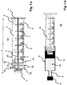
- FIG.b illustrates the use of the piston rod 15 ' Figure 1.a in a prefilled syringe 20.
- the syringe 20 comprises a syringe body 8 with a nozzle 9 arranged on the front side of the syringe body 8, a cap 11 closing the nozzle 9, a plunger 12 arranged in the syringe body 8, which closes the interior of the syringe body 8 in a liquid-tight manner, and the piston rod 15 ' Figure 1a which is connected to the piston 12 via its connecting section 1.
- the connection between the piston 12 and the piston rod 15 ' is provided here by a screw connection.
- a thread is also provided inside the piston 12, but this is not shown in the figure.
- the outer diameter D or D F of the piston rod 15 ′ and / or the ring elements 2a, 2b, 2c and / or the wing elements 3a, 3b can be the same as the inner diameter of the syringe body 8.
- the outer diameter D or D F of the piston rod 15' and / or the ring elements 2a, 2b, 2c and / or the wing elements 3a, 3b is smaller than the inner diameter of the syringe body 8.
- the outer diameter D or D F is preferably reduced by approximately 0.5 mm to 5 mm compared to the inner diameter of the syringe body 8.
- the pre-filled syringe 20 can, for example, be filled via its initially open rear side and then closed with the piston 12.
- the piston 12 can, however, also be introduced into the syringe body 8 with the piston rod 15 ′ already screwed into the piston 12.
- the position of the plunger 12 in the pre-filled syringe body 8 and the position of the three ring elements 2a, 2b, 2c on the plunger rod 15 ' are preferably coordinated so that in a first step, when the plunger rod 15' with its connecting section 1 on the plunger 12 is attached, the two front rings 2a, 2b are already arranged in the interior of the syringe body 8 and are preferably guided through the inside of the syringe body 8.
- the piston rod 15 ' is first by the two front ring elements 2a, 2b and the front wing elements 3a and then also by the rear wing elements 3b in the Syringe body 8 out.
- the rear third ring 2c supports the guidance of the piston rod 15 'during the final, firm connection of the piston rod 15' to the piston 12.
- the three rings 2a, 2b, 2c are in the state in which the piston rod 15 'is completely connected to the piston 12 is connected, preferably screwed into the piston 12, is positioned in the interior of the syringe body 8.
- the ring elements 2a, 2b, 2c prove to be advantageous because they prevent tilting over the entire circumference of 360 °.
- the wing elements 3a, 3b prove to be advantageous since they allow a longer guidance along the longitudinal axis of the piston rod 15 '. The present invention combines these advantages.
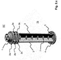
- Figure 2.a to 2.c show a piston rod 15 ′′ according to a second embodiment of the invention. Only the differences to the piston rod 15 'from FIG Figure 1.a explained. For all other components, refer to the description above Figure 1.a referenced. There is no scale on the piston rod 15 ".
- the wing elements 3a, 3b which connect the three ring elements 2a, 2b, 2c to one another, do not have the same outer diameter as the three ring elements 2a, 2b, 2c.
- the outside diameter D F of the wing elements 3a, 3b is smaller than the outside diameter D of the three ring elements 2a, 2b, 2c.
- the outer diameter D F of the wing elements 3a, 3b is preferably reduced by approximately 4 mm to 8 mm compared to the outer diameter D of the ring elements 2a, 2b, 2c. In the present case there are exactly three ring elements which are located in the front region of the piston rod 15 '.
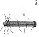
- FIG. 3 a piston rod 15 '"according to a third embodiment of the invention.
- the structure of this piston rod 15'” corresponds essentially to the structure of the piston rod 15 "from the Figure 2.a to 2.c .
- the present piston rod 15 '" only has different dimensions, since it is designed for a syringe 20 with a capacity of up to about 20 ml to 30 ml.
- the piston rod 15'" has a diameter D with 13 mm D 23 mm and / or a length L with 100 mm L 150 mm.
- the distance R between the ring elements is also here 2 mm R 8 mm.
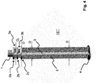
- FIG. 4 a piston rod 15 "" according to a fourth embodiment of the invention.
- the structure of this piston rod 15 “” essentially corresponds to the structure of the piston rods 15 "and 15 '" from the Figures 2.a to 2.c and 3 .
- the present piston rod 15 ′′ ′′ merely has different dimensions, since it is designed for a syringe 20 with a capacity of up to approximately 10 ml to 15 ml.
- the piston rod 15 ′′ ′′ has a diameter D with 8 mm D 18 mm and / or a length L with 80 mm L mm 110 mm.
- the distance R between the ring elements is here 2 mm R 8 mm.
- no stabilizing elements 7 are provided on the piston rod 15 ′′ ′′.
Abstract
Die Erfindung betrifft eine Kolbenstange für einen mit einer medizinischen Flüssigkeit vorgefüllten Spritzenkörper und eine vorgefüllte Spritze umfassend eine solche Kolbenstange. Die vorgefüllte Spritze (20) umfasst die folgenden Komponenten: einen mit einer medizinischen Flüssigkeit (10) befüllten Spritzenkörper (8), der an einer Vorderseite eine Düse (9) aufweist, die mit einer Kappe (11) verschlossen ist, und der an einer Rückseite mit einem verschiebbaren Kolben (12) verschlossen ist, und einen über die Rückseite in den Spritzenkörper (8) einführbare Kolbenstange (15', 15", 15"', 15""), die an einer Vorderseite einen Verbindungsabschnitt (1) aufweist, über den die Kolbenstange (15', 15", 15'", 15"") mit dem Kolben (12) verbindbar ist, wobei an einer Rückseite des Verbindungsabschnitts (1) wenigstens drei Ringelemente (2a, 2b, 2c), die sich zumindest abschnittweise um eine Längsachse der Kolbenstange (15', 15", 15'", 15"") erstrecken, so an der Kolbenstange (15', 15", 15'", 15"") angeordnet sind, dass sie sich, wenn die Kolbenstange (15', 15", 15'", 15"") vollständig mit dem Kolben (12) verbunden ist, in dem Spritzenkörper befinden. Die drei Ringelemente unterstützen ein koaxiales Verbinden der Kolbenstange mit dem in der Spritze positionierten Kolben. Die drei Ringelemente ermöglichen dem Anwender beim Verbinden der Kolbenstange mit dem Kolben eine haptische und/oder akustische Kontrolle, ob er die Kolbenstange ordnungsgemäß mit dem Kolben verbindet.The invention relates to a plunger rod for a syringe body pre-filled with a medical liquid and a pre-filled syringe comprising such a plunger rod. The prefilled syringe (20) comprises the following components: a syringe body (8) filled with a medical liquid (10), which has a nozzle (9) on a front side, which is closed with a cap (11), and which on a Rear side is closed with a displaceable plunger (12), and a plunger rod (15 ', 15 ", 15"', 15 "") which can be inserted into the syringe body (8) and which has a connecting section (1) on a front side , via which the piston rod (15 ', 15 ", 15'", 15 "") can be connected to the piston (12), with at least three ring elements (2a, 2b, 2c) on a rear side of the connecting section (1) extend at least in sections around a longitudinal axis of the piston rod (15 ', 15 ", 15'", 15 "") so that they are arranged on the piston rod (15 ', 15 ", 15'", 15 "") when the plunger rod (15 ', 15 ", 15'", 15 "") is fully connected to the plunger (12), are located in the syringe body. The three ring elements assist in a coaxial connection of the plunger rod with the plunger positioned in the syringe. When connecting the piston rod to the piston, the three ring elements enable the user to haptic and / or acoustic control as to whether he is properly connecting the piston rod to the piston.
Description
Die Erfindung betrifft eine Kolbenstange für einen mit einer medizinischen Flüssigkeit vorgefüllten Spritzenkörper sowie eine Spritze umfassend die Kolbenstange und den mit der medizinischen Flüssigkeit vorgefüllten Spritzenkörper.The invention relates to a plunger rod for a syringe body pre-filled with a medical liquid and a syringe comprising the plunger rod and the syringe body pre-filled with the medical liquid.
Aus der
Der Erfindung liegt die Aufgabe zugrunde, eine verbesserte Kolbenstange bereitzustellen. Das Einsetzen, insbesondere das Einschrauben, der Kolbenstange in den Kolben soll verbessert werden. Insbesondere soll eine Leckage durch ein Verkippen des Kolbens möglichst vermieden werden. Ferner soll die Führung der Kolbenstange in dem Spritzenkörper verbessert werden, insbesondere bei der Verwendung der Spritze in einer Spritzenpumpe.The invention is based on the object of providing an improved piston rod. The insertion, in particular the screwing, of the piston rod into the piston is to be improved. In particular, leakage caused by tilting the piston should be avoided as far as possible. Furthermore, the guidance of the plunger rod in the syringe body is to be improved, especially when the syringe is used in a syringe pump.
Diese Aufgabe wird durch Gegenstände mit den Merkmalen nach den unabhängigen Ansprüchen gelöst. Vorteilhafte Ausführungsformen sind Gegenstand der abhängigen Ansprüche, der Beschreibung sowie der Zeichnungen.This object is achieved by subjects having the features according to the independent claims. Advantageous embodiments are the subject matter of the dependent claims, the description and the drawings.
Die erfindungsgemäße vorgefüllte Spritze umfasst die folgenden Bestandteile: einen mit einer medizinischen Flüssigkeit befüllten Spritzenkörper, der an einer Vorderseite eine Düse aufweist, die mit einer Kappe verschlossen ist, und der an einer Rückseite mit einem verschiebbaren Kolben verschlossen ist, und einen über die Rückseite in den Spritzenkörper einführbare Kolbenstange, die an einer Vorderseite einen Verbindungsabschnitt aufweist, über den die Kolbenstange mit dem Kolben verbindbar ist, wobei an einer Rückseite des Verbindungsabschnitts wenigstens drei Ringelemente, die sich zumindest abschnittweise um eine Längsachse der Kolbenstange erstrecken, so an der Kolbenstange angeordnet sind, dass sie sich, wenn die Kolbenstange vollständig mit dem Kolben verbunden ist, in dem Spritzenkörper befinden. Die Spritze ist dabei in ihrem initialen Zustand. D.h. der Kolben wurde noch nicht bewegt zum Ausstoßen der Flüssigkeit.The prefilled syringe according to the invention comprises the following components: a syringe body filled with a medical liquid, which has a nozzle on a front side which is closed with a cap and which is closed on a rear side with a displaceable plunger, and one via the rear side in the syringe body insertable plunger rod which has a connecting section on a front side via which the plunger rod can be connected to the plunger, with at least three ring elements, which extend at least in sections around a longitudinal axis of the plunger rod, being arranged on the plunger rod on a rear side of the connecting section that they are in the syringe body when the plunger rod is fully connected to the plunger. The syringe is in its initial state. This means that the piston has not yet been moved to expel the liquid.
Die drei Ringelemente unterstützen ein koaxiales Verbinden der Kolbenstange mit dem Kolben. Die Ringelemente erweisen sich zum einen als vorteilhaft, da sie ein Verkippen über den gesamten Umfang von 360° verhindern. Zum anderen ermöglichen die drei Ringelemente dem Anwender beim Verbinden der Kolbenstange mit dem Kolben eine haptische und/oder akustische Kontrolle. Verbindet beispielsweise der Anwender die Kolbenstange ordnungsgemäß gerade mit dem Kolben, bekommt er keine haptische und/oder akustische Rückmeldung. Versucht der Anwender dagegen unbeabsichtigt die Kolbenstange nicht ordnungsgemäß schief mit dem Kolben zu verbinden, so kann er insbesondere den Übergang der Kolbenstange von dem mittleren Ringelement zu dem hinteren Ringelement an der Kante der hinteren Spritzenkörperöffnung als eine Art Sprung, vorzugsweise verbunden mit einer Art Klicken wahrnehmen. Der Anwender kann dadurch erkennen, dass er versucht, die Kolbenstange nicht ordnungsgemäß mit dem Kolben zu verbinden und daraufhin die Lage der Kolbenstange entsprechend korrigieren.The three ring elements support a coaxial connection of the piston rod with the piston. On the one hand, the ring elements prove to be advantageous because they prevent tilting over the entire circumference of 360 °. On the other hand, the three ring elements enable the user to haptic and / or acoustic control when connecting the piston rod to the piston. For example, if the user connects the piston rod properly and straight to the piston, he does not receive any haptic and / or acoustic feedback. If, on the other hand, the user inadvertently tries to connect the plunger rod to the plunger incorrectly at an angle, he can in particular perceive the transition of the plunger rod from the middle ring element to the rear ring element at the edge of the rear syringe body opening as a kind of jump, preferably connected with a kind of click . This enables the user to recognize that he is trying to improperly connect the piston rod to the piston and then correct the position of the piston rod accordingly.
Vorzugsweise sind die Position des Kolbens in dem vorgefüllten Spritzenkörper und die Position der drei Ringelemente an der Kolbenstange so aufeinander abgestimmt, dass in einem ersten Schritt, wenn die Kolbenstange mit ihrem Verbindungsabschnitt an dem Kolben angesetzt wird, bereits die beiden vorderen Ringe im Inneren des Spritzenkörpers angeordnet sind. Beim Verbinden, beispielsweise Einschrauben, wird die Kolbenstange zunächst durch die beiden vorderen Ringelemente geführt. Der hintere dritte Ring unterstützt die Führung der Kolbenstange beim finalen, festen Verbinden der Kolbenstange mit dem Kolben.The position of the plunger in the prefilled syringe body and the position of the three ring elements on the plunger rod are preferably coordinated so that in a first step, when the connecting section of the plunger rod is attached to the plunger, the two front rings are already inside the syringe body are arranged. When connecting, for example screwing in, the piston rod is first guided through the two front ring elements. The rear third ring supports the guidance of the piston rod during the final, firm connection of the piston rod with the piston.
Spätestens sind die drei Ringelemente in dem Zustand, in dem die Kolbenstange vollständig mit dem Kolben verbunden ist, vorzugsweise in den Kolben eingeschraubt, ist, im Inneren des Spritzenkörpers positioniert.At the latest, the three ring elements are positioned in the interior of the syringe body in the state in which the piston rod is completely connected to the piston, preferably screwed into the piston.
Gemäß einer ersten Ausführungsform ist ein Außendurchmesser der drei Ringelemente gleich einem Innendurchmesser des Spritzenkörpers oder etwas kleiner als ein Innendurchmesser des Spritzenkörpers. Dadurch können die drei Ringelemente beim Verbinden der Kolbenstange mit dem Kolben und später beim Bewegen des Kolbens zum Ausstoßen der Flüssigkeit auf einer Innenseite des Spritzenkörpers geführt werden. Vorzugsweise ist der Außendurchmesser der drei Ringelemente gleich.According to a first embodiment, an outer diameter of the three ring elements is equal to an inner diameter of the syringe body or somewhat smaller than an inner diameter of the syringe body. As a result, the three ring elements can be guided on an inside of the syringe body when the piston rod is connected to the piston and later when the piston is moved to expel the liquid. The outer diameter of the three ring elements is preferably the same.
In einer weiteren Ausführungsform sind, vorzugsweise jeweils, zwischen den Ringelementen über den Umfang der Kolbenstangen verteilte Flügelelemente oder Rippen angeordnet, welche sich radial nach außen erstrecken. Vorzugsweise verbinden die Flügelelemente die Ringelemente miteinander. Die Flügelelemente erweisen sich als vorteilhaft, da sie eine längere, abschnittsweise kontinuierliche Führung entlang der Längsachse der Kolbenstange ermöglichen.In a further embodiment, wing elements or ribs are arranged, preferably in each case, between the ring elements over the circumference of the piston rods and which extend radially outward. The wing elements preferably connect the ring elements to one another. The wing elements prove to be advantageous because they allow a longer, continuous guidance in sections along the longitudinal axis of the piston rod.
In einer Ausgestaltung sind, insbesondere jeweils, zwischen den Ringelementen mindestens vier Flügelelemente, vorzugsweise unter einem Winkel von 90° zueinander, angeordnet. Dadurch soll eine möglichst koaxiale Führung der Kolbenstange unterstützt werden. Vorzugsweise weisen die Flügelelemente einen Außendurchmesser auf, der gleich dem Innendurchmesser des Spritzenkörpers ist oder etwas kleiner ist als der Innendurchmesser des Spritzenkörpers. In einer ersten Ausführungsform besitzen die Flügelelemente einen Außendurchmesser, der gleich dem Außendurchmesser der Ringelemente ist. Dadurch wird die Führung der Kolbenstange noch verbessert. In einer zweiten Ausführungsform besitzen die Flügelelemente einen Außendurchmesser, der kleiner als ein Außendurchmesser der Ringelemente ist. Dadurch wird beim Verbinden der Kolbenstange mit dem Kolben und/oder beim Einführen der Kolbenstange in den Spritzenkörper die haptische und/oder akustische Kontrolle verbessert. In einer Ausgestaltung ist der Außendurchmesser der Flügelelemente gegenüber dem Außendurchmesser der Ringelemente um 1 mm bis 10 mm, vorzugsweise um 4 mm bis 8 mm reduziert.In one embodiment, in particular in each case, at least four wing elements are arranged between the ring elements, preferably at an angle of 90 ° to one another. This is intended to support the most coaxial guidance of the piston rod. The wing elements preferably have an outer diameter which is equal to the inner diameter of the syringe body or is somewhat smaller than the inner diameter of the syringe body. In a first embodiment, the wing elements have an outside diameter which is equal to the outside diameter of the ring elements. This improves the guidance of the piston rod. In a second embodiment, the wing elements have an outer diameter which is smaller than an outer diameter of the ring elements. This improves the haptic and / or acoustic control when the piston rod is connected to the piston and / or when the piston rod is inserted into the syringe body. In one embodiment, the outer diameter of the wing elements is reduced by 1 mm to 10 mm, preferably by 4 mm to 8 mm, compared to the outer diameter of the ring elements.
Die vorgefüllte Spritze kann zum Beispiel in einer Überverpackung bereitgestellt werden. Ist zum Beispiel die medizinische Flüssigkeit sauerstoffempfindlich und der Spritzenkörper nicht ausreichend sauerstoffimpermeabel, so kann die Spritze in einer sauerstoffimpermeablen Überverpackung verpackt sein, zum Beispiel in einem Blister. Die Kolbenstange kann zum Beispiel bereits an dem Kolben vormontiert sein. Sie kann aber auch nicht vormontiert neben dem Spritzenkörper in der Überverpackung liegen. Daher liegt im Bereich der Erfindung auch eine Überverpackung mit einem Innenraum, in dem die vorstehend beschriebene erfindungsgemäße Spritze eingeschlossen ist.For example, the prefilled syringe can be provided in an overpack. For example, is the medical fluid sensitive to oxygen and the Syringe body not sufficiently oxygen-impermeable, the syringe can be packed in an oxygen-impermeable overpack, for example in a blister. The piston rod can, for example, already be preassembled on the piston. But it can also not be pre-assembled next to the syringe body in the outer packaging. Therefore, the scope of the invention also includes an overpack with an interior space in which the above-described syringe according to the invention is enclosed.
Weiterhin liegt im Bereich der Erfindung auch die Kolbenstange, insbesondere für eine oder für die vorstehend genannte vorgefüllte Spritze. Die Kolbenstange umfasst einen vorderseitigen Verbindungsabschnitt, über den die Kolbenstange mit einem Kolben verbindbar ist. Dabei sind an einer Rückseite des Verbindungsabschnitts wenigstens drei Ringelemente angeordnet, welche sich zumindest abschnittweise um eine Längsachse der Kolbenstange erstrecken. Die drei Ringelemente sind, vorzugsweise jeweils, in einem Abstand R zueinander angeordnet sind mit 0,5 mm ≤ R ≤ 20mm, bevorzugt 1 mm ≤ R ≤ 10mm, besonders bevorzugt 2 mm ≤ R ≤ 8mm. Die Ringelemente besitzen beispielsweise eine Dicke von etwa 0,5 mm bis etwa 5 mm, vorzugsweise von etwa 1 mm bis etwa 3 mm. Die Kolbenstange besitzt einen Durchmesser D mit 8 mm ≤ D ≤ 30 mm und/oder eine Länge L mit 80 mm ≤ L ≤ 150 mm.Furthermore, the plunger rod, in particular for or for the pre-filled syringe mentioned above, is also within the scope of the invention. The piston rod comprises a front-side connecting section via which the piston rod can be connected to a piston. In this case, at least three ring elements are arranged on a rear side of the connecting section, which ring elements extend at least in sections around a longitudinal axis of the piston rod. The three ring elements are, preferably in each case, arranged at a distance R from one another with 0.5
Ferner wird auch noch eine Spritze beansprucht, umfassend einen Spritzenkörper, einen Kolben und die vorstehend beschriebene Kolbenstange, wobei der Kolben so in dem Spritzenkörper positionierbar ist und die drei Ringelemente so an der Kolbenstange angeordnet sind, dass sie sich, wenn die Kolbenstange vollständig mit dem Kolben verbunden ist, in dem Spritzenkörper befinden. Vorzugsweise ist der Spritzenkörper mit einer medizinischen Flüssigkeit vorgefüllt.Furthermore, a syringe is also claimed, comprising a syringe body, a plunger and the plunger rod described above, wherein the plunger can be positioned in the syringe body and the three ring elements are arranged on the plunger rod so that, when the plunger rod is completely with the Plunger is connected, located in the syringe body. The syringe body is preferably prefilled with a medical liquid.
Die vorgefüllte Spritze kann zum Beispiel ein Fassungsvolumen von 5 ml bis 100 ml haben. Die medizinische Flüssigkeit kann beispielsweise eine Flüssigkeit zur enteralen und/oder parenteralen Ernährung und/oder zur Infusion sein oder umfassen. Die medizinische Flüssigkeit kann durch eine Lösung und/oder durch eine Emulsion bereitgestellt werden. Die medizinische Flüssigkeit kann auch medizinische Wirkstoffe enthalten. Gemäß einer Ausführungsform ist oder umfasst die medizinische Flüssigkeit das Arzneistofffluid Propofol, insbesondere eine Propofol-Emulsion. Propofol wird beschrieben durch den chemischen Namen 2,6-Diisopropylphenol (IUAPC).The pre-filled syringe can, for example, have a capacity of 5 ml to 100 ml. The medical liquid can be or comprise, for example, a liquid for enteral and / or parenteral nutrition and / or for infusion. The medical fluid can be provided by a solution and / or by an emulsion. The medicinal liquid can also contain medicinal active ingredients. According to one embodiment, the medical liquid is or comprises the drug fluid propofol, in particular a propofol emulsion. Propofol is described by the chemical name 2,6-diisopropylphenol (IUAPC).
Der Spritzenkörper kann aus Kunststoff geformt sein, welcher eines der folgenden Polymere umfasst: Cyclo-Olefin-Copolymer, Cyclo-Olefin-Polymer oder Crystal Clear Polymer. Ein derartiger Kunststoffbehälter ist gegen Lösungsmittel widerstandsfähig. Insbesondere kann ein derartiger Kunststoffbehälter zur Lagerung von Propofol, das als Lösungsmittel wirkt, verwendet werden. Vorzugsweise sind die Außenseite des Kolbens und/oder die Innenseite des Spritzenkörpers zumindest abschnittsweise mit einem Gleitmittel bedeckt, vorzugsweise silikonisiert.The syringe body can be molded from plastic, which comprises one of the following polymers: cyclo-olefin copolymer, cyclo-olefin polymer or crystal clear Polymer. Such a plastic container is resistant to solvents. In particular, such a plastic container can be used to store propofol, which acts as a solvent. The outside of the plunger and / or the inside of the syringe body are preferably covered, at least in sections, with a lubricant, preferably siliconized.
Gemäß einer Ausführungsform ist die Kunststoffkolbenstange aus Kunststoff geformt, welcher vorzugsweise eines der folgenden Polymere umfasst: Cyclo-Olefin-Copolymer, Cyclo-Olefin-Polymer oder Crystal Clear Polymer, oder sie ist aus Polypropylen geformt.According to one embodiment, the plastic piston rod is molded from plastic, which preferably comprises one of the following polymers: cyclo-olefin copolymer, cyclo-olefin polymer or crystal clear polymer, or it is molded from polypropylene.
Die Erfindung wird nachfolgend anhand von Ausführungsbeispielen in Verbindung mit den Zeichnungen im Einzelnen beschrieben werden.The invention will be described in detail below on the basis of exemplary embodiments in conjunction with the drawings.
Es zeigen:
- Fig. 1.a
- eine Seitenansicht einer Kolbenstange gemäß einer ersten Ausführungsform der Erfindung;
- Fig. 1.b
- eine Seitenansicht einer erfindungsgemäßen vorgefüllten Spritze mit der Kolbenstange aus
Figur 1.a ; - Fig. 2.a
- eine Seitenansicht einer Kolbenstange gemäß einer zweiten Ausführungsform der Erfindung;
- Fig. 2.b
- eine Seitenansicht einer erfindungsgemäßen vorgefüllten Spritze mit der Kolbenstange aus
Figur 2.a ; - Fig. 2.c
- eine perspektivische Ansicht der Kolbenstange gemäß der zweiten Ausführungsform der Erfindung aus
Figur 2.a ; - Fig. 3
- eine perspektivische Ansicht einer Kolbenstange gemäß einer dritten Ausführungsform der Erfindung und
- Fig. 4
- eine perspektivische Ansicht einer Kolbenstange gemäß einer vierten Ausführungsform der Erfindung;
- Fig. 1.a
- a side view of a piston rod according to a first embodiment of the invention;
- Fig. 1.b
- a side view of a prefilled syringe according to the invention with the plunger rod
Figure 1.a ; - Fig. 2.a
- a side view of a piston rod according to a second embodiment of the invention;
- Fig. 2.b
- a side view of a prefilled syringe according to the invention with the plunger rod
Figure 2.a ; - Fig. 2.c
- a perspective view of the piston rod according to the second embodiment of the invention
Figure 2.a ; - Fig. 3
- a perspective view of a piston rod according to a third embodiment of the invention and
- Fig. 4
- a perspective view of a piston rod according to a fourth embodiment of the invention;
Die Vorderseite der Kolbenstange 15' wird bereitgestellt durch einen Verbindungsabschnitt 1, über den die Kolbenstange 15' mit einem hier nicht dargestellten Kolben 12 verbunden wird (siehe dazu
Der kreuzförmige Querschnitt der Kolbenstange 15' setzt sich auch zwischen den drei Ringelementen 2a, 2b, 2c fort. Unter Vernachlässigung des Flansches 4 und des Verbindungsabschnitts 1 ist der Durchmesser D der Kolbenstange entlang der Längsachse gleich oder im Wesentlichen gleich. Dadurch werden zwischen den drei Ringelementen 2a, 2b, 2c sogenannte Flügelelemente 3a, 3b oder Rippen gebildet. Die vorderen, hier vier, Flügelelemente 3a verbinden den vorderen Ring 2a mit dem mittleren Ring 2b. Die hinteren, hier vier, Flügelelemente 3b verbinden den mittleren Ring 2b mit dem hinteren Ring 2b. Die Ringelemente 2a, 2b, 2c und die Flügelelemente 3a, 3b ermöglichen ein möglichst koaxiales Einführen der Kolbstange 15' in den Spritzenkörper 8 und dadurch ein möglichst koaxiales Einschrauben der Kolbstange 15' in den Kolben 12 (siehe dazu
Der Außendurchmesser D bzw. DF der Kolbenstange 15' und/oder der Ringelemente 2a, 2b, 2c und/oder der Flügelelemente 3a, 3b kann gleich dem Innendurchmesser des Spritzenkörpers 8 sein. Um eine vereinfachte Bewegung des Kolbenstange 15' in dem Spritzenkörper 8 zu ermöglichen, ist insbesondere der Außendurchmesser D bzw. DF der Kolbenstange 15' und/oder der Ringelemente 2a, 2b, 2c und/oder der Flügelelemente 3a, 3b kleiner als der Innendurchmesser des Spritzenkörpers 8. Vorzugsweise ist der Außendurchmesser D bzw. DF um etwa 0,5 mm bis 5 mm reduziert gegenüber dem Innendurchmesser des Spritzenkörpers 8.The outer diameter D or D F of the
Die vorgefüllte Spritze 20 kann zum Beispiel über Ihre zunächst offene Rückseite befüllt und dann mit dem Kolben 12 verschlossen werden. Die Kolbenstange 15' kann dann zu einem späteren Zeitpunkt mit dem Kolben 12 verbunden werden, zum Beispiel kurz vor der Anwendung. Der Kolben 12 kann aber auch zum Beispiel mit bereits in den Kolben 12 eingeschraubter Kolbenstange 15' in den Spritzenkörper 8 eingebracht werden.The
Die Position des Kolbens 12 in dem vorgefüllten Spritzenkörper 8 und die Position der drei Ringelemente 2a, 2b, 2c an der Kolbenstange 15' sind vorzugsweise so aufeinander abgestimmt, dass in einem ersten Schritt, wenn die Kolbenstange 15' mit ihrem Verbindungsabschnitt 1 an dem Kolben 12 angesetzt wird, bereits die beiden vorderen Ringe 2a, 2b im Inneren des Spritzenkörpers 8 angeordnet und vorzugsweise durch die Innenseite des Spritzenkörpers 8 geführt sind. Beim Einschrauben wird die Kolbenstange 15' zunächst durch die beiden vorderen Ringelemente 2a, 2b und die vorderen Flügelelemente 3a und dann auch durch die hinteren Flügelelemente 3b in dem Spritzenkörper 8 geführt. Der hintere dritte Ring 2c unterstützt die Führung der Kolbenstange 15' beim finalen, festen Verbinden der Kolbenstange 15' mit dem Kolben 12. Spätestens sind die drei Ringe 2a, 2b, 2c in dem Zustand, in dem die Kolbenstange 15' vollständig mit dem Kolben 12 verbunden ist, vorzugsweise in den Kolben 12 eingeschraubt, ist, im Inneren des Spritzenkörpers 8 positioniert. Die Ringelemente 2a, 2b, 2c erweisen sich als vorteilhaft, da sie ein Verkippen über den gesamte Umfang von 360° verhindern. Die Flügelelemente 3a, 3b erweisen sich als vorteilhaft, da sie eine längere Führung entlang der Längsachse der Kolbenstange 15' ermöglichen. Die vorliegende Erfindung verbindet diese Vorteile miteinander.The position of the
Dadurch kann insbesondere dem Anwender beim Einschrauben der Kolbenstange 15" in den Kolben 12 eine haptische und/oder akustische Kontrolle ermöglicht werden. Schraubt der Anwender die Kolbenstange 15" ordnungsgemäß gerade in den Kolben 12 ein, bekommt er keine haptische und/oder akustische Rückmeldung. Versucht der Anwender dagegen die Kolbenstange 15" unbeabsichtigt und nicht ordnungsgemäß schief in den Kolben 12 einzuschrauben, so kann er insbesondere den Übergang der Kolbenstange 15" von dem mittleren Ringelement 2b zu dem hinteren Ringelement 2c an der Kante 14 in der hinteren Spritzenkörperöffnung (siehe dazu
Weiterhin zeigt
Abschließend zeigt
Es ist dem Fachmann ersichtlich, dass die beschriebenen Ausführungsformen beispielhaft zu verstehen sind. Die Erfindung ist nicht auf diese beschränkt sondern kann in vielfältiger Weise variiert werden, ohne das Wesen der Erfindung zu verlassen. Merkmale einzelner Ausführungsformen und die im allgemeinen Teil der Beschreibung genannten Merkmale können jeweils untereinander als auch miteinander kombiniert werden.It is evident to the person skilled in the art that the embodiments described are to be understood as examples. The invention is not restricted to these but can be varied in many ways without departing from the essence of the invention. Features of individual embodiments and the features mentioned in the general part of the description can be combined with one another or with one another.
Claims (15)
an einer Rückseite des Verbindungsabschnitts (1) wenigstens drei Ringelemente (2a, 2b, 2c), die sich zumindest abschnittweise um eine Längsachse der Kolbenstange (15', 15", 15'", 15"") erstrecken, zur Führung der Kolbenstange (15', 15", 15'", 15"") in dem Spritzenkörper (8) so an der Kolbenstange (15', 15", 15'", 15"") angeordnet sind, dass sie sich, wenn die Kolbenstange (15', 15", 15'", 15"") vollständig mit dem Kolben (12) verbunden ist, in dem Spritzenkörper befinden.Comprising a prefilled syringe (20)
on a rear side of the connecting section (1) at least three ring elements (2a, 2b, 2c), which extend at least in sections around a longitudinal axis of the piston rod (15 ', 15 ", 15'", 15 "") for guiding the piston rod ( 15 ', 15 ", 15'", 15 "") are arranged in the syringe body (8) on the plunger rod (15 ', 15 ", 15'", 15 "") so that when the plunger rod ( 15 ', 15 ", 15'", 15 "") is completely connected to the plunger (12), located in the syringe body.
an einer Rückseite des Verbindungsabschnitts (1) wenigstens drei Ringelemente (2a, 2b, 2c) zur Führung der Kolbenstange (15', 15", 15'", 15"") in dem Spritzenkörper (8) angeordnet sind, welche sich zumindest abschnittsweise um eine Längsachse der Kolbenstange (15', 15", 15'", 15"") erstrecken und welche in einem Abstand R angeordnet sind mit 0,5 mm ≤ R ≤ 20mm, vorzugsweise 1 mm ≤ R ≤ 10mm.Piston rod (15 ', 15 ", 15"', 15 "") for a prefilled syringe (20) according to one of the preceding claims, comprising a front connecting section (1) via which the piston rod (15 ', 15 ", 15'",15"") can be connected to a piston (12), wherein
on a rear side of the connecting section (1) at least three ring elements (2a, 2b, 2c) for guiding the piston rod (15 ', 15 ", 15'", 15 "") are arranged in the syringe body (8), which are at least partially about a longitudinal axis of the piston rod (15 ', 15 ", 15'", 15 "") and which are arranged at a distance R with 0.5 mm R 20mm, preferably 1 mm R 10mm.
Applications Claiming Priority (3)
| Application Number | Priority Date | Filing Date | Title |
|---|---|---|---|
| EP15000587 | 2015-03-02 | ||
| EP16707143.0A EP3265154B1 (en) | 2015-03-02 | 2016-03-02 | Plunger rod comprising at least three annular elements for a prefilled syringe |
| PCT/EP2016/054351 WO2016139215A1 (en) | 2015-03-02 | 2016-03-02 | Plunger rod comprising at least three annular elements for a prefilled syringe |
Related Parent Applications (2)
| Application Number | Title | Priority Date | Filing Date |
|---|---|---|---|
| EP16707143.0A Division EP3265154B1 (en) | 2015-03-02 | 2016-03-02 | Plunger rod comprising at least three annular elements for a prefilled syringe |
| EP16707143.0A Division-Into EP3265154B1 (en) | 2015-03-02 | 2016-03-02 | Plunger rod comprising at least three annular elements for a prefilled syringe |
Publications (1)
| Publication Number | Publication Date |
|---|---|
| EP3760260A1 true EP3760260A1 (en) | 2021-01-06 |
Family
ID=52596725
Family Applications (2)
| Application Number | Title | Priority Date | Filing Date |
|---|---|---|---|
| EP16707143.0A Active EP3265154B1 (en) | 2015-03-02 | 2016-03-02 | Plunger rod comprising at least three annular elements for a prefilled syringe |
| EP20186074.9A Pending EP3760260A1 (en) | 2015-03-02 | 2016-03-02 | Piston rod with at least three ring elements for a prefilled syringe |
Family Applications Before (1)
| Application Number | Title | Priority Date | Filing Date |
|---|---|---|---|
| EP16707143.0A Active EP3265154B1 (en) | 2015-03-02 | 2016-03-02 | Plunger rod comprising at least three annular elements for a prefilled syringe |
Country Status (11)
| Country | Link |
|---|---|
| US (2) | US10543319B2 (en) |
| EP (2) | EP3265154B1 (en) |
| JP (1) | JP6872490B2 (en) |
| CN (1) | CN107427642B (en) |
| AU (1) | AU2016227737B2 (en) |
| BR (1) | BR112017017822B1 (en) |
| CA (1) | CA2978090C (en) |
| DE (1) | DE202016008940U1 (en) |
| ES (1) | ES2833369T3 (en) |
| HK (1) | HK1245684A1 (en) |
| WO (1) | WO2016139215A1 (en) |
Families Citing this family (2)
| Publication number | Priority date | Publication date | Assignee | Title |
|---|---|---|---|---|
| DE202016008940U1 (en) * | 2015-03-02 | 2020-11-30 | Fresenius Kabi Austria Gmbh | Piston rod with at least three ring elements for a pre-filled syringe |
| EP4190377A4 (en) * | 2020-08-20 | 2024-01-03 | Terumo Corp | Pre-filled syringe |
Citations (7)
| Publication number | Priority date | Publication date | Assignee | Title |
|---|---|---|---|---|
| WO2001097885A1 (en) * | 2000-06-19 | 2001-12-27 | Terumo Kabushiki Kaisha | Syringe |
| JP2002272843A (en) * | 2001-03-15 | 2002-09-24 | Terumo Corp | Syringe |
| WO2010139793A1 (en) * | 2009-06-04 | 2010-12-09 | Novo Nordisk A/S | Mixing device with piston coupling arrangement |
| JP2011072394A (en) * | 2009-09-29 | 2011-04-14 | Terumo Corp | Syringe and prefilled syringe |
| EP2484393A1 (en) * | 2009-09-30 | 2012-08-08 | Terumo Kabushiki Kaisha | Pre-filled syringe |
| WO2014053560A1 (en) | 2012-10-04 | 2014-04-10 | Fresenius Kabi Deutschland Gmbh | Application arrangement with a medicinal substance fluid |
| WO2014122782A1 (en) * | 2013-02-08 | 2014-08-14 | テルモ株式会社 | Pre-filled syringe |
Family Cites Families (17)
| Publication number | Priority date | Publication date | Assignee | Title |
|---|---|---|---|---|
| AUPN615095A0 (en) * | 1995-10-24 | 1995-11-16 | Astra Pharmaceuticals Pty Ltd | Tamper evident syringe design |
| JPH10277153A (en) * | 1997-04-04 | 1998-10-20 | Asahi Chem Ind Co Ltd | Injection unit filled with medicine |
| CA2379409C (en) * | 1999-07-15 | 2007-05-15 | Bracco International B.V. | Plunger for syringe |
| JP2001314506A (en) * | 2000-05-02 | 2001-11-13 | Daiichi Radioisotope Labs Ltd | Plunger rod for injection cylinder |
| US7708719B2 (en) | 2001-11-02 | 2010-05-04 | Meridian Medical Technologies, Inc. | Medicament container, a medicament dispensing kit for administering medication and a method for packaging the same |
| US20060275336A1 (en) * | 2003-05-19 | 2006-12-07 | De Villiers, Malan | Preparation of an osteoinductive agent |
| EP1849490A4 (en) * | 2005-02-15 | 2009-09-16 | Top Kk | Syringe |
| CN2897287Y (en) * | 2006-04-19 | 2007-05-09 | 山东威高集团医用高分子制品股份有限公司 | Low-resistance syringe |
| EP1923085A1 (en) * | 2006-11-17 | 2008-05-21 | Sanofi-Aventis Deutschland GmbH | Dosing and drive mechanism for drug delivery device |
| PL2020245T3 (en) * | 2007-07-31 | 2012-04-30 | Al Chi Mi A S R L | Method for making a device for ophthalmic treatments |
| JP5428157B2 (en) * | 2007-12-27 | 2014-02-26 | 大日本印刷株式会社 | Packaging bag for prefilled syringe |
| JP2010246842A (en) * | 2009-04-20 | 2010-11-04 | Usui Seisakusho:Kk | Syringe |
| JP5767208B2 (en) * | 2010-03-29 | 2015-08-19 | テルモ株式会社 | Prefilled syringe |
| US9433729B2 (en) * | 2010-09-14 | 2016-09-06 | Neomed, Inc. | Enteral syringe |
| AU2011314422B2 (en) * | 2010-10-11 | 2015-01-15 | Shl Group Ab | Medicament delivery device |
| CN107206177B (en) * | 2014-12-12 | 2021-06-25 | 维克森林大学健康科学 | Incremental injector |
| DE202016008940U1 (en) * | 2015-03-02 | 2020-11-30 | Fresenius Kabi Austria Gmbh | Piston rod with at least three ring elements for a pre-filled syringe |
-
2016
- 2016-03-02 DE DE202016008940.5U patent/DE202016008940U1/en active Active
- 2016-03-02 ES ES16707143T patent/ES2833369T3/en active Active
- 2016-03-02 AU AU2016227737A patent/AU2016227737B2/en active Active
- 2016-03-02 BR BR112017017822-2A patent/BR112017017822B1/en active IP Right Grant
- 2016-03-02 JP JP2017546064A patent/JP6872490B2/en active Active
- 2016-03-02 EP EP16707143.0A patent/EP3265154B1/en active Active
- 2016-03-02 EP EP20186074.9A patent/EP3760260A1/en active Pending
- 2016-03-02 US US15/555,220 patent/US10543319B2/en active Active
- 2016-03-02 CN CN201680013197.XA patent/CN107427642B/en active Active
- 2016-03-02 WO PCT/EP2016/054351 patent/WO2016139215A1/en active Application Filing
- 2016-03-02 CA CA2978090A patent/CA2978090C/en active Active
-
2018
- 2018-04-08 HK HK18104562.0A patent/HK1245684A1/en unknown
-
2020
- 2020-01-27 US US16/752,784 patent/US11571520B2/en active Active
Patent Citations (7)
| Publication number | Priority date | Publication date | Assignee | Title |
|---|---|---|---|---|
| WO2001097885A1 (en) * | 2000-06-19 | 2001-12-27 | Terumo Kabushiki Kaisha | Syringe |
| JP2002272843A (en) * | 2001-03-15 | 2002-09-24 | Terumo Corp | Syringe |
| WO2010139793A1 (en) * | 2009-06-04 | 2010-12-09 | Novo Nordisk A/S | Mixing device with piston coupling arrangement |
| JP2011072394A (en) * | 2009-09-29 | 2011-04-14 | Terumo Corp | Syringe and prefilled syringe |
| EP2484393A1 (en) * | 2009-09-30 | 2012-08-08 | Terumo Kabushiki Kaisha | Pre-filled syringe |
| WO2014053560A1 (en) | 2012-10-04 | 2014-04-10 | Fresenius Kabi Deutschland Gmbh | Application arrangement with a medicinal substance fluid |
| WO2014122782A1 (en) * | 2013-02-08 | 2014-08-14 | テルモ株式会社 | Pre-filled syringe |
Also Published As
| Publication number | Publication date |
|---|---|
| JP2018510688A (en) | 2018-04-19 |
| DE202016008940U1 (en) | 2020-11-30 |
| ES2833369T3 (en) | 2021-06-15 |
| CA2978090A1 (en) | 2016-09-09 |
| EP3265154A1 (en) | 2018-01-10 |
| CN107427642B (en) | 2021-04-02 |
| CA2978090C (en) | 2023-12-12 |
| BR112017017822B1 (en) | 2023-02-07 |
| CN107427642A (en) | 2017-12-01 |
| HK1245684A1 (en) | 2018-08-31 |
| US20200155765A1 (en) | 2020-05-21 |
| EP3265154B1 (en) | 2020-11-18 |
| US10543319B2 (en) | 2020-01-28 |
| WO2016139215A1 (en) | 2016-09-09 |
| AU2016227737B2 (en) | 2020-07-23 |
| US20180050158A1 (en) | 2018-02-22 |
| JP6872490B2 (en) | 2021-05-19 |
| AU2016227737A1 (en) | 2017-09-07 |
| US11571520B2 (en) | 2023-02-07 |
| BR112017017822A2 (en) | 2018-04-10 |
Similar Documents
| Publication | Publication Date | Title |
|---|---|---|
| DE69726531T2 (en) | Lockable protective sleeve for pre-filled syringe | |
| DE69724349T2 (en) | Syringe plunger | |
| DE60021275T2 (en) | MULTIPLE DOSE SYRINGE | |
| DE10009814B4 (en) | Disposable injector | |
| DE102004060146C5 (en) | Autoinjector with locking of the drug container | |
| DE2909002C3 (en) | Single use syringe | |
| DE602004003549T2 (en) | SAFETY PIN | |
| DE69725220T2 (en) | Piston device with bypass for use in the cylinder of a multi-chamber syringe | |
| EP2300081B1 (en) | Ampoule having ampoule holder | |
| DE60218618T2 (en) | Syringe-like container for a liquid drug | |
| DE2744439C2 (en) | Disposable injection syringe | |
| EP2533908B1 (en) | Discharge device having a locking element | |
| WO2004047895A1 (en) | Device for securing injection needles | |
| DE1491819B1 (en) | Syringe rack assembly | |
| EP2300080B1 (en) | Mixing device for a two-chamber ampoule | |
| DE2259825A1 (en) | INJECTION SYRINGE | |
| EP1523356B1 (en) | Administration device comprising a plunger rod with a return lock | |
| EP3265154B1 (en) | Plunger rod comprising at least three annular elements for a prefilled syringe | |
| EP1417981B1 (en) | Medical Syringe | |
| DE19927201A1 (en) | Syringe for medical purposes | |
| EP0498376A1 (en) | Self destructive disposable syringe | |
| DE202007011833U1 (en) | The safety device | |
| CH397157A (en) | Injection syringe | |
| EP2954915A1 (en) | Container made of several components | |
| DE10102054A1 (en) | Ampule syringe in the form of an ampule has a conical section, a planned break line and a closable connector piece at one end, and a piston with a piston rod seating at the other end |
Legal Events
| Date | Code | Title | Description |
|---|---|---|---|
| PUAI | Public reference made under article 153(3) epc to a published international application that has entered the european phase |
Free format text: ORIGINAL CODE: 0009012 |
|
| STAA | Information on the status of an ep patent application or granted ep patent |
Free format text: STATUS: THE APPLICATION HAS BEEN PUBLISHED |
|
| AC | Divisional application: reference to earlier application |
Ref document number: 3265154 Country of ref document: EP Kind code of ref document: P |
|
| AK | Designated contracting states |
Kind code of ref document: A1 Designated state(s): AL AT BE BG CH CY CZ DE DK EE ES FI FR GB GR HR HU IE IS IT LI LT LU LV MC MK MT NL NO PL PT RO RS SE SI SK SM TR |
|
| STAA | Information on the status of an ep patent application or granted ep patent |
Free format text: STATUS: REQUEST FOR EXAMINATION WAS MADE |
|
| 17P | Request for examination filed |
Effective date: 20210617 |
|
| RBV | Designated contracting states (corrected) |
Designated state(s): AL AT BE BG CH CY CZ DE DK EE ES FI FR GB GR HR HU IE IS IT LI LT LU LV MC MK MT NL NO PL PT RO RS SE SI SK SM TR |