EP3733488B1 - Nutzfahrzeug - Google Patents
Nutzfahrzeug Download PDFInfo
- Publication number
- EP3733488B1 EP3733488B1 EP18895993.6A EP18895993A EP3733488B1 EP 3733488 B1 EP3733488 B1 EP 3733488B1 EP 18895993 A EP18895993 A EP 18895993A EP 3733488 B1 EP3733488 B1 EP 3733488B1
- Authority
- EP
- European Patent Office
- Prior art keywords
- vehicle body
- link
- hydraulic cylinder
- hydraulic
- traveling
- Prior art date
- Legal status (The legal status is an assumption and is not a legal conclusion. Google has not performed a legal analysis and makes no representation as to the accuracy of the status listed.)
- Active
Links
Images


Classifications
-
- B—PERFORMING OPERATIONS; TRANSPORTING
- B60—VEHICLES IN GENERAL
- B60G—VEHICLE SUSPENSION ARRANGEMENTS
- B60G17/00—Resilient suspensions having means for adjusting the spring or vibration-damper characteristics, for regulating the distance between a supporting surface and a sprung part of vehicle or for locking suspension during use to meet varying vehicular or surface conditions, e.g. due to speed or load
- B60G17/015—Resilient suspensions having means for adjusting the spring or vibration-damper characteristics, for regulating the distance between a supporting surface and a sprung part of vehicle or for locking suspension during use to meet varying vehicular or surface conditions, e.g. due to speed or load the regulating means comprising electric or electronic elements
- B60G17/016—Resilient suspensions having means for adjusting the spring or vibration-damper characteristics, for regulating the distance between a supporting surface and a sprung part of vehicle or for locking suspension during use to meet varying vehicular or surface conditions, e.g. due to speed or load the regulating means comprising electric or electronic elements characterised by their responsiveness, when the vehicle is travelling, to specific motion, a specific condition, or driver input
- B60G17/0165—Resilient suspensions having means for adjusting the spring or vibration-damper characteristics, for regulating the distance between a supporting surface and a sprung part of vehicle or for locking suspension during use to meet varying vehicular or surface conditions, e.g. due to speed or load the regulating means comprising electric or electronic elements characterised by their responsiveness, when the vehicle is travelling, to specific motion, a specific condition, or driver input to an external condition, e.g. rough road surface, side wind
-
- B—PERFORMING OPERATIONS; TRANSPORTING
- B60—VEHICLES IN GENERAL
- B60G—VEHICLE SUSPENSION ARRANGEMENTS
- B60G17/00—Resilient suspensions having means for adjusting the spring or vibration-damper characteristics, for regulating the distance between a supporting surface and a sprung part of vehicle or for locking suspension during use to meet varying vehicular or surface conditions, e.g. due to speed or load
-
- B—PERFORMING OPERATIONS; TRANSPORTING
- B60—VEHICLES IN GENERAL
- B60G—VEHICLE SUSPENSION ARRANGEMENTS
- B60G3/00—Resilient suspensions for a single wheel
- B60G3/02—Resilient suspensions for a single wheel with a single pivoted arm
- B60G3/12—Resilient suspensions for a single wheel with a single pivoted arm the arm being essentially parallel to the longitudinal axis of the vehicle
- B60G3/14—Resilient suspensions for a single wheel with a single pivoted arm the arm being essentially parallel to the longitudinal axis of the vehicle the arm being rigid
-
- B—PERFORMING OPERATIONS; TRANSPORTING
- B60—VEHICLES IN GENERAL
- B60K—ARRANGEMENT OR MOUNTING OF PROPULSION UNITS OR OF TRANSMISSIONS IN VEHICLES; ARRANGEMENT OR MOUNTING OF PLURAL DIVERSE PRIME-MOVERS IN VEHICLES; AUXILIARY DRIVES FOR VEHICLES; INSTRUMENTATION OR DASHBOARDS FOR VEHICLES; ARRANGEMENTS IN CONNECTION WITH COOLING, AIR INTAKE, GAS EXHAUST OR FUEL SUPPLY OF PROPULSION UNITS IN VEHICLES
- B60K7/00—Disposition of motor in, or adjacent to, traction wheel
- B60K7/0015—Disposition of motor in, or adjacent to, traction wheel the motor being hydraulic
-
- B—PERFORMING OPERATIONS; TRANSPORTING
- B62—LAND VEHICLES FOR TRAVELLING OTHERWISE THAN ON RAILS
- B62D—MOTOR VEHICLES; TRAILERS
- B62D5/00—Power-assisted or power-driven steering
- B62D5/06—Power-assisted or power-driven steering fluid, i.e. using a pressurised fluid for most or all the force required for steering a vehicle
- B62D5/10—Power-assisted or power-driven steering fluid, i.e. using a pressurised fluid for most or all the force required for steering a vehicle characterised by type of power unit
- B62D5/12—Piston and cylinder
-
- B—PERFORMING OPERATIONS; TRANSPORTING
- B62—LAND VEHICLES FOR TRAVELLING OTHERWISE THAN ON RAILS
- B62D—MOTOR VEHICLES; TRAILERS
- B62D57/00—Vehicles characterised by having other propulsion or other ground- engaging means than wheels or endless track, alone or in addition to wheels or endless track
- B62D57/02—Vehicles characterised by having other propulsion or other ground- engaging means than wheels or endless track, alone or in addition to wheels or endless track with ground-engaging propulsion means, e.g. walking members
- B62D57/024—Vehicles characterised by having other propulsion or other ground- engaging means than wheels or endless track, alone or in addition to wheels or endless track with ground-engaging propulsion means, e.g. walking members specially adapted for moving on inclined or vertical surfaces
-
- B—PERFORMING OPERATIONS; TRANSPORTING
- B62—LAND VEHICLES FOR TRAVELLING OTHERWISE THAN ON RAILS
- B62D—MOTOR VEHICLES; TRAILERS
- B62D61/00—Motor vehicles or trailers, characterised by the arrangement or number of wheels, not otherwise provided for, e.g. four wheels in diamond pattern
- B62D61/12—Motor vehicles or trailers, characterised by the arrangement or number of wheels, not otherwise provided for, e.g. four wheels in diamond pattern with variable number of ground engaging wheels, e.g. with some wheels arranged higher than others, or with retractable wheels
-
- B—PERFORMING OPERATIONS; TRANSPORTING
- B25—HAND TOOLS; PORTABLE POWER-DRIVEN TOOLS; MANIPULATORS
- B25J—MANIPULATORS; CHAMBERS PROVIDED WITH MANIPULATION DEVICES
- B25J9/00—Program-controlled manipulators
- B25J9/16—Program controls
- B25J9/1656—Program controls characterised by programming, planning systems for manipulators
- B25J9/1669—Program controls characterised by programming, planning systems for manipulators characterised by special application, e.g. multi-arm co-operation, assembly, grasping
-
- B—PERFORMING OPERATIONS; TRANSPORTING
- B60—VEHICLES IN GENERAL
- B60G—VEHICLE SUSPENSION ARRANGEMENTS
- B60G2200/00—Indexing codes relating to suspension types
- B60G2200/10—Independent suspensions
- B60G2200/18—Multilink suspensions, e.g. elastokinematic arrangements
-
- B—PERFORMING OPERATIONS; TRANSPORTING
- B60—VEHICLES IN GENERAL
- B60G—VEHICLE SUSPENSION ARRANGEMENTS
- B60G2200/00—Indexing codes relating to suspension types
- B60G2200/40—Indexing codes relating to the wheels in the suspensions
- B60G2200/44—Indexing codes relating to the wheels in the suspensions steerable
-
- B—PERFORMING OPERATIONS; TRANSPORTING
- B60—VEHICLES IN GENERAL
- B60G—VEHICLE SUSPENSION ARRANGEMENTS
- B60G2202/00—Indexing codes relating to the type of spring, damper or actuator
- B60G2202/40—Type of actuator
- B60G2202/41—Fluid actuator
- B60G2202/413—Hydraulic actuator
-
- B—PERFORMING OPERATIONS; TRANSPORTING
- B60—VEHICLES IN GENERAL
- B60G—VEHICLE SUSPENSION ARRANGEMENTS
- B60G2204/00—Indexing codes related to suspensions per se or to auxiliary parts
- B60G2204/40—Auxiliary suspension parts; Adjustment of suspensions
- B60G2204/422—Links for mounting suspension elements
-
- B—PERFORMING OPERATIONS; TRANSPORTING
- B60—VEHICLES IN GENERAL
- B60G—VEHICLE SUSPENSION ARRANGEMENTS
- B60G2204/00—Indexing codes related to suspensions per se or to auxiliary parts
- B60G2204/62—Adjustable continuously, e.g. during driving
-
- B—PERFORMING OPERATIONS; TRANSPORTING
- B60—VEHICLES IN GENERAL
- B60G—VEHICLE SUSPENSION ARRANGEMENTS
- B60G2300/00—Indexing codes relating to the type of vehicle
- B60G2300/08—Agricultural vehicles
-
- B—PERFORMING OPERATIONS; TRANSPORTING
- B60—VEHICLES IN GENERAL
- B60G—VEHICLE SUSPENSION ARRANGEMENTS
- B60G2300/00—Indexing codes relating to the type of vehicle
- B60G2300/40—Variable track or wheelbase vehicles
- B60G2300/402—Extra load carrying wheels, e.g. tag axles
-
- B—PERFORMING OPERATIONS; TRANSPORTING
- B60—VEHICLES IN GENERAL
- B60G—VEHICLE SUSPENSION ARRANGEMENTS
- B60G2500/00—Indexing codes relating to the regulated action or device
- B60G2500/30—Height or ground clearance
-
- B—PERFORMING OPERATIONS; TRANSPORTING
- B60—VEHICLES IN GENERAL
- B60G—VEHICLE SUSPENSION ARRANGEMENTS
- B60G2500/00—Indexing codes relating to the regulated action or device
- B60G2500/40—Steering
-
- B—PERFORMING OPERATIONS; TRANSPORTING
- B60—VEHICLES IN GENERAL
- B60G—VEHICLE SUSPENSION ARRANGEMENTS
- B60G2800/00—Indexing codes relating to the type of movement or to the condition of the vehicle and to the end result to be achieved by the control action
- B60G2800/24—Steering, cornering
Definitions
- the present invention relates to a work vehicle suitable for traveling on a highly rugged road surface.
- Patent Literature 1 discloses a prime mover having a plurality of elongated, segmented legs with individual steerable drive means on each so as to enable the prime mover to be easily moved to and positioned properly in a wide variety of environments and terrains.
- the wheel support arrangement according to the above-described conventional configuration is intended to enable traveling with maintaining the vehicle body under an appropriate posture even in the presence of unevenness on the traveling road surface through bending/stretching of the link mechanism. Then, it is conceivable to apply such wheel support arrangement to an agricultural work vehicle that travels in a work site having unevenness on the traveling road surface.
- a plurality of turning mechanisms configured to support the plurality of articulated link mechanisms respectively to the vehicle body with allowing changing of the respective postures thereof about a vertical axis.
- the posture of the articulation mechanism will have its posture changed about the vertical axis, whereby the right/left orientation of the traveling device can be changed.
- the vehicle can travel to make a turn with no excessive lateral force being applied to the traveling device.
- the traveling devices supported by the articulated link mechanisms are disposed on more laterally outer side than the laterally outer end of the vehicle body, so that they can be supported under a stable state with a wide ground-contacting distance in the lateral direction.
- the turning mechanism is disposed between the vehicle body and the articulated link mechanism as seen in a plan view, with a turning operation, the traveling device can be set to a posture widely spread to further laterally outer side, whereby further stabilization of the posture of the ground-contacting posture is made possible.
- a work oil feeding tube such as a hydraulic hose that connects the oil source to the plurality of hydraulic cylinders can be pivotally displaced.
- the intermediate portion of the work oil feeding tube such as a hydraulic hose has its position held by the feeding pipe holding portion, there will be less possibility of damage to the work oil feeding tube as being entrapped by the articulated link mechanism for instance.
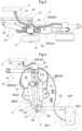
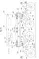
- a work vehicle includes a vehicle body 1 in the form of an approximately rectangular frame for supporting the entire vehicle, a plurality of ("four" in specific) traveling devices 2, a plurality of auxiliary wheels 3 provided in correspondence with the respective plurality of traveling devices 2, bending link mechanisms 4 (an example of “articulated link mechanism”) as “vehicle body supporting portions” for supporting the vehicle body 1 with allowing changes of respective positions of the plurality of traveling devices 2, a plurality of hydraulic cylinders 5, 6 capable of changing postures of the respective bending link mechanisms 4, and a work oil feeding device 7 as a hydraulic (pressure oil) source for feeding work oil to the plurality of hydraulic cylinders 5, 6.
- a hydraulic (pressure oil) source for feeding work oil to the plurality of hydraulic cylinders 5, 6.
- Each one of the plurality of traveling devices 2 includes a drive wheel 8 supported to be rotatable about a horizontal axis and a hydraulic motor 9 incorporated within a bearing portion of the drive wheel 8.
- Each traveling device 2 can rotatably drive the drive wheel 8 associated therewith by operating the hydraulic motor 9.
- this definition when definition is to be made for the front/rear direction of the vehicle body, this definition is made along the vehicle body advancing direction.
- this definition is made as seen in the vehicle body advancing direction.
- the direction denoted with a sign (A) in Fig. 1 represents the vehicle body front/rear direction
- the direction denoted with a sign (B) in Fig. 2 represents the vehicle body right/left direction.
- the vehicle body 1 includes a support frame 10 in the form of a rectangular frame that surrounds the entire circumference of the vehicle body 1 and that also supports it entirely.
- the work oil feeding device 7 is accommodated and supported inside the vehicle body 1.
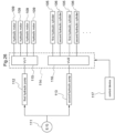
- the work oil feeding device 7 includes a hydraulic pump driven by an engine and feeding work oil to the plurality of hydraulic cylinders 5 and the plurality of hydraulic motors 9, a hydraulic control unit for controlling the work oil fed from the hydraulic pump, a work oil tank, etc. and effects feeding and discharging of the work oil, adjustment of its flow rate/amount, etc.
- control device 11 for controlling operations of the work oil feeding device 7. Control operations by the control device 11 will not be detailed herein. Briefly, however, based on instruction information inputted via an unillustrated manual input device (e.g. a remote controller, etc.) or preset and prestored instruction information, feeding states of work oil to the hydraulic cylinders 5 and the hydraulic motors 9 are controlled.
- an unillustrated manual input device e.g. a remote controller, etc.
- preset and prestored instruction information feeding states of work oil to the hydraulic cylinders 5 and the hydraulic motors 9 are controlled.
- the four traveling devices 2 are supported to the vehicle body 1 to be liftable up/down via the respective bending link mechanisms 4.
- Each bending link mechanism 4 is supported to the vehicle body 1 with its orientation being changeable about a vertical axis by a turning mechanism 12.
- the bending link mechanism 4 is supported to a support frame 10 to be pivotable about a vertical axis Y via the turning mechanism 12.
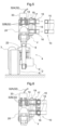
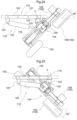
- the turning mechanism 12 includes a vehicle body side supporting portion 13 (see Fig. 3 and Fig. 4 ) which is coupled to the support frame 10 and which also pivotally supports the bending link mechanism 4; and a turning hydraulic cylinder (to be referred to as "turning cylinder” hereinafter) 14 for turning the bending link mechanism 4.
- the vehicle body side supporting portion 13 includes a coupling member 16 which is engaged with a pair of upper and lower front/rear oriented frame bodies 15, in the form of angular cylinders provided at lateral portions of the support frame 10, by sandwiching the frame bodies 15 from lateral outer sides thereof and which also is to be removably bolt-connected thereto; an outer side pivot bracket 17 disposed at an outer side portion in the vehicle body front/rear direction of the coupling member 16; an inner side pivot bracket 18 disposed at an inner side portion in the vehicle body front/rear direction of the coupling member 16; and a vertically oriented pivot shaft 19 supported to the outer side pivot bracket 17, so that the vehicle body side supporting portion 13 supports the bending link mechanism 4 with allowing pivotal movements thereof about the vertical axis Y of the pivot shaft 19.
- the bending link mechanism 4 includes a base end portion 20 which has its position fixed in the vertical direction and which is supported to the vehicle body side supporting portion 13 to be pivotable about the vertical axis Y; a first link 21 having one end portion thereof supported to a lower portion of the base end portion 20 to be pivotable about a horizontal axis X1; and a second link 22 having one end portion thereof supported to the other end portion of the first link 21 to be pivotable about a horizontal axis X2 and having the other end portion thereof supported to the traveling device 2.
- the first link 21 is disposed at a position closer to the vehicle body and supported to be pivotable about the vehicle body side coupling portion (the lower portion of the base end portion 20).
- the base end portion 20 is provided in the form of a rectangular frame as seen in a plan view; and at a position offset inward in the vehicle body lateral width direction, the base end portion 20 is supported to the outer side pivot bracket 17 of the vehicle body side supporting portion 13 to be pivotable about the vertical axis Y via the pivot shaft 19.
- the turning cylinder 14 has one end portion thereof pivotally coupled to the inner side pivot bracket 18 and has the other end portion thereof pivotally coupled to a portion of the base end portion 20 laterally displaced relative to the pivot shaft 19.
- a support shaft 25 provided at one end of the first link 21 is pivotally supported; and the first link 21 is coupled to the lower portion of the base end portion 20 to be pivotable about the axis of the support shaft 25.
- the first link 21 includes a base end side arm portion 21b and an other end side arm portion 21a. At one end side portion of the first link 21, there is integrally formed the base end side arm portion 21b which extends obliquely outwardly upwards. At the other end side portion of the first link 21, there is integrally formed the other end side arm portion 21a which extends obliquely upwardly outwards.
- the second link 22 is bifurcated with a pair of right and left band-plate like plate bodies 22a, 22b, as seen in a plan view.
- the pair of plate bodies 22a, 22b keep the spacing distance from each other at the coupling portions of the second link 22 relative to the first link 21.
- a coupling pivot shaft 31 to be coupled with the first link 21 is pivotally supported.
- the traveling device 2 is supported. As shown in Fig.
- an L-shaped extension portion 22A that extends in the form of an approximate L-letter in the direction away from the vehicle body 1; and at the extension end portion of this L-shaped extension portion 22A, the traveling device 2 is supported.
- Each one of the four bending link mechanisms 4 includes a first hydraulic cylinder 5 capable of changing the pivotal posture of the first link 21 relative to the vehicle body 1 and a second hydraulic cylinder 6 capable of changing the pivotal posture of the second link 22 relative to the first link 21.
- the first hydraulic cylinder 5 and the second hydraulic cylinder 6 are disposed in concentration in the vicinity of the first link 21 respectively.
- the first link 21, the first hydraulic cylinder 5 and the second hydraulic cylinder 6 are disposed between the pair of plate bodies 22a, 22b of the second link 22 as seen in the plan view. As shown in Figs. 3 and 4 , the first hydraulic cylinder 5 is disposed on the vehicle body front/rear direction inner side relative to the first link 21 and provided along the longitudinal direction of the first link 21.
- the first hydraulic cylinder 5 has an upper end portion of its cylinder tube 5A operably coupled to a lower portion of the base end portion 20 via a first interlocking member 26 that is formed arcuate.
- the upper end portion of the cylinder tube 5A is operably coupled to a base end side portion of the first link 21 via a further second interlocking member 27.
- the first interlocking member 26 and the second interlocking member 27 have respective opposed ends thereof pivotally coupled to each other to be pivotable relative to each other.
- the lower end portion (leading end portion) of the piston rod 5B of the first hydraulic cylinder 5 is pivotally coupled to the other end side arm portion 21a formed integrally in the first link 21. Therefore, the piston rod 5B side of the first hydraulic cylinder 5 is pivotally coupled to the other end side arm portion 21a as the coupled portion on the side of the first link 21.
- the second hydraulic cylinder 6 is disposed on the opposite side to the first hydraulic cylinder 5, namely, on the vehicle body front/rear direction outer side relative to the first link 21 and provided along the longitudinal direction of the first link 21.
- the second hydraulic cylinder 6 has an upper end portion of its cylinder tube 6A operably coupled to the base end side arm portion 21b formed integrally to the base end side of the first link 21.
- the lower end portion (leading end portion) of the piston rod 6B as the other end portion of the second hydraulic cylinder 6 is operably coupled to an arm portion 29 formed integrally to the base end side portion of the second link 22 via a third interlocking member 28 that is formed arcuate.
- the lower end portion of the piston rod 6B of the second hydraulic cylinder 6 is operably coupled also to the pivotal end side portion of the first link 21 via a further/fourth interlocking member 30.
- the third interlocking member 28 and the fourth interlocking member 30 have respective opposed ends thereof pivotally coupled to be pivotable relative to each other.
- the first hydraulic cylinder 5 for operating the first link 21 is configured to pivot the first link 21 in association with an expansion/contraction operation associated with work oil feeding from the work oil feeding device 7 included in the vehicle body 1.
- the second hydraulic cylinder 6 If the second hydraulic cylinder 6 is expanded/contracted when the first hydraulic cylinder 5 is stopped, the second link 22 and the traveling device 2 will be pivoted together about a horizontal axis X2 at the coupling portion with the first link 21 and the second link 22 with maintaining the posture of the first link 21 relative to the vehicle body 1 constant.
- the auxiliary wheel 3 is supported.
- the auxiliary wheel 3 is constituted of a wheel having an approximately equal outside diameter to that of the drive wheel 8 of the traveling device 2.
- the coupling pivot shaft 31, that pivotally couples the first link 21 to the second link 22 extends to project outward of the second link 22 in the vehicle body lateral width direction.
- the auxiliary wheel 3 is rotatably supported on the coupling pivot shaft 31 at the extended/projected portion thereof. That is, the coupling pivot shaft 31 that pivotally couples the first link 21 to the second link 22 is configured to act also as a pivot shaft for the auxiliary wheel 3, thus simplification of arrangement through component co-utilization being sought for.
- the bending link mechanism 4, the traveling device 2, the auxiliary wheel 3, the first hydraulic cylinder 5 and the second hydraulic cylinder 6 respectively are supported to the outer side pivot bracket 17 to be pivotable together about the vertical axis Y of the pivot support shaft 19. And, these will be pivotally operated together by expanding/contracting the turning cylinder 14. Turning operation is possible for each increment of approximately 45 degrees from a straight traveling state in which the traveling device 2 is oriented in the front/rear direction to the left turning direction and the right turning direction, respectively.
- the first hydraulic cylinder 5 and the second hydraulic cylinder 6 With feeding/discharging of work oil to/from the work oil feeding device 7 to/from the first hydraulic cylinder 5 and the second hydraulic cylinder 6 of each one of the plurality of bending link mechanisms 4, the first hydraulic cylinder 5 and the second hydraulic cylinder 6 can be expanded/contracted. With execution of flow rate adjustment of the work oil to the hydraulic motor 9, the rotational speed of the hydraulic motor 9, i.e. of the drive wheel 8, can be changed.
- a hydraulic hose 32 (an example of "work oil feeding tube”) for feeding the work oil.
- a work oil relaying device 33 (an example of “feeding pipe holding portion") for holding in position the hydraulic hose 32 for feeding the work oil from the work oil feeding device 7 to the first hydraulic cylinder 5, the second hydraulic cylinder 6 and the hydraulic motor 9, respectively.
- the work oil relaying device 33 functions to relay-connect the hydraulic hose 32 that connects the work oil feeding device 7 with each hydraulic device (hydraulic cylinder 5 and hydraulic motor 9) in the bending link mechanism 4 corresponding thereto, and the device 33 is fixedly attached to the base end portion 20 under a position-fixed state. Therefore, the hydraulic hose 32 is separated into a body side hose portion 32A closer to the vehicle body 1 than the work oil relaying device 33, and a leading end side hose portion 32B closer to the hydraulic device.
- this work vehicle includes various sensors. Specifically, the work vehicle includes a first head side pressure sensor S 1 and a first cap side (remote-from-head side) pressure sensor S2 included in the respective first hydraulic cylinder 5; and a second cap side pressure sensor S3 and a second head side (remote-from-cap side) pressure sensor S4 included in the respective second hydraulic cylinder 6.
- the first head side pressure sensor S1 detects an oil pressure of the head side chamber of the first hydraulic cylinder 5.
- the first cap side pressure sensor S2 detects an oil pressure of the cap side chamber of the first hydraulic cylinder 5.
- the second cap side pressure sensor S3 detects an oil pressure of the head side chamber of the second hydraulic cylinder 6.
- the second head side pressure sensor S4 detects an oil pressure of the cap side chamber of the second hydraulic cylinder 6. Further, though not shown, each of the hydraulic cylinders as described above (the first hydraulic cylinder 5, the second hydraulic cylinder 6 and the turning cylinder 14) incorporates a stroke sensor capable of detecting an expansion/contraction stroke amount and is configured to feedback its operational state to the control device 11.
- each of the pressure sensors S1, S2, S3, S4 may detect (estimate) the oil pressure of the cap side chamber or the head side chamber associated therewith, and thus each sensor may be disposed in a pipe extending from the valve mechanism to the cap side or head side chamber associated therewith.
- a force needed for supporting the vehicle body 1 is calculated and based on this result, feeding of work oil to the respective first hydraulic cylinder 5 and second hydraulic cylinder 6 will be controlled.
- a cylinder propelling force for the first hydraulic cylinder 5 will be calculated from a pressure difference between the cap side chamber and the head side chamber of the first hydraulic cylinder 5.
- a cylinder propelling force for the second hydraulic cylinder 6 will be calculated from a pressure difference between the cap side chamber and the head side chamber of the second hydraulic cylinder 6.
- the vehicle body 1 includes an acceleration sensor S5 constituted of e.g. a triaxial acceleration sensor or the like. Based on a detection result of the acceleration sensor S5, tilts of the vehicle body 1 to the front/rear sides and right/left sides are detected. And, based on the result, the posture of the vehicle body 1 is controlled. Namely, in order to allow the posture of the vehicle body 1 to become a target posture, feeding of work oil to the respective first hydraulic cylinder 5 and second hydraulic cylinder 6 will be controlled.
- an acceleration sensor S5 constituted of e.g. a triaxial acceleration sensor or the like.
- the traveling device 2 includes a rotation sensor S6 for detecting a rotational speed of the drive wheel 8.
- a rotation sensor S6 for detecting a rotational speed of the drive wheel 8. In operation, based on the rotational speed of the drive wheel 8 calculated by the rotation sensor S6, feeding of work oil to the hydraulic motor 9 will be controlled in such a manner that the rotational speed of the drive wheel 8 may become a target value.
- the work vehicle according to the instant embodiment is configured such that the traveling devices 2 are supported via the respective bending link mechanisms 4 and also that the postures of the bending link mechanisms 4 are changed by the hydraulic cylinders 5, 6. Moreover, driving of traveling is done by the hydraulic motor 9 also. Therefore, the work vehicle is suitable for an agricultural work as being robust against adverse influence from water content, fine dust or the like, unlike an electric motor for instance.
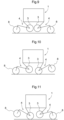
- traveling is possible in any one of a plurality of different kinds of traveling modes. Namely, as shown in Fig. 9 , a four-wheel traveling mode is possible in which all of the four traveling devices 2 (specifically the drive wheels 8) are placed in contact with the ground surface and also all of the four auxiliary wheels 3 are lifted afloat off the ground surface; and, as shown in Fig.
- a two-wheel traveling mode is possible in which the drive wheels 8 disposed on one vehicle body front/rear direction side are set afloat and the auxiliary wheels 3 corresponding thereto are placed in contact with the ground surface, and also the drive wheels 8 disposed on the other vehicle body front/rear direction side are placed in contact with the ground surface and the auxiliary wheels 3 corresponding thereto are set afloat.
- the relation between the drive wheels 8 and the auxiliary wheels 3 is reversed in the vehicle body front/rear direction. Namely, as shown in Fig. 11 , the drive wheels 8 disposed on vehicle body front/rear one side are placed in contact with the ground surface and the auxiliary wheels 3 corresponding thereto are lifted afloat the ground surface, and the drive wheels 8 disposed on the other vehicle body front/rear side are set afloat and the auxiliary wheels 3 corresponding thereto are placed in contact with the ground surface.
- each one of the four sets of bending link mechanisms 4 is configured to be switched over between a traveling state in which the drive wheels 8 are placed in contact with the ground surface and the auxiliary wheels 3 corresponding thereto are lifted afloat the ground surface, and a free movement state in which the auxiliary wheels 3 are placed in contact with the ground surface and the drive wheels 8 corresponding thereto are lifted afloat the ground surface.
- all of the four sets of drive wheels 8 are set under the traveling state; and in the two-wheel traveling state described above, two sets of drive wheels 8 on one vehicle body front/rear side of the four sets of drive wheels 8 are set to the traveling state and the auxiliary wheels 3 on the other side are placed in contact with the ground surface for the free movement condition.
- the vehicle in addition to the traveling modes on a flat ground surface described above, as unique additional uses thereof, the vehicle may be used in further modes as follow.
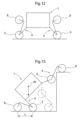
- the traveling devices 2 (specifically the drive wheels 8) can be placed on a high place.
- an object M as an object of transport will be lifted up by the two sets of drive wheels 8 on the other side in the vehicle body front/rear direction.
- traveling can be made with maintaining the posture of the vehicle body 1 by the two sets of drive wheels 8 and the auxiliary wheels 3 on onside in the vehicle body front/rear direction, whereby the object M may be transported.
- the posture of the bending link mechanism 4 will be changed to an extended posture in which the drive wheel 8 and the auxiliary wheel 3 respectively is located on more outer side in the vehicle body front/rear direction than the vehicle body front/rear outer end.
- the height of the vehicle body 1 is set to a low position by setting the first link 21 and the second link 22 as close as possible to the horizontal posture. Under this condition, the vehicle travels as climbing a slope. In this traveling mode, the ground contact width along the vehicle body front/rear direction is increased, so that even on a largely tilted slope, stable traveling is possible without toppling.
- the vehicle body 1 is largely elevated off the ground surface. With this, for instance, a work is possible with keeping the vehicle body upwards as striding over a ridge. Even when an agricultural produce planted on the ridge has grown, such operations as chemical spraying, harvesting, etc. are possible from above the produce.
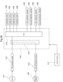
- a work vehicle includes a vehicle body 101 in the form of an approximately rectangular frame for supporting the entire vehicle, a plurality of ("four" in specific) traveling devices 102 driven by hydraulic motors 109, a plurality of auxiliary wheels 103 provided in correspondence with the respective plurality of traveling devices 102, bending link mechanisms 104 (an example of “vehicle body supporting portion” and “articulate link mechanism”) for supporting the plurality of traveling devices 102 respectively to the vehicle body 101 with allowing changes of respective positions of the plurality of traveling devices 102, a plurality of hydraulic cylinders 105, 106 capable of changing postures of the respective bending link mechanisms 104, and a work oil feeding deice 107 as a hydraulic (pressure oil) source for feeding work oil to the hydraulic motors 109 and the plurality of hydraulic cylinders 105, 106.
- a hydraulic (pressure oil) source for feeding work oil to the hydraulic motors 109 and the plurality of hydraulic cylinders 105, 106.
- Each one of the plurality of traveling devices 102 includes a drive wheel 108 supported to be rotatable about a horizontal axis and the hydraulic motor 109 incorporated within a bearing portion of the drive wheel 108.
- Each traveling device 102 can rotatably drive the drive wheel 108 associated therewith by operating the hydraulic motor 109.
- the vehicle body 101 includes a support frame 110 in the form of a rectangular frame that surrounds the entire circumference of the vehicle body 101 and that also supports it entirely.
- the work oil feeding device 107 is accommodated and supported inside the vehicle body 101.
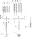
- the work oil feeding device 107 includes two hydraulic pumps 112, 113 that are driven by an engine 111 mounted on the vehicle, a hydraulic control unit 114 configured to control feeding states of work oil fed from the hydraulic pumps 112, 113 to the plurality of hydraulic cylinders 105 and to the plurality of hydraulic motors 109, a work oil tank (not shown) for reserving an amount of work oil therein, etc. and effects feeding/discharging of the work oil, adjustment of its flow rate (amount), etc.
- a first hydraulic pump 112 for feeding work oil to the plurality of hydraulic motors 109 and a second hydraulic pump 113 for feeding work oil to the plurality of hydraulic cylinders 105, 106.
- the first hydraulic pump 112 and the second hydraulic pump 113 are both driven by the engine 111.
- the hydraulic control unit 114 includes a first hydraulic control section (VU1) 115 for controlling work oil feeding condition to the respective hydraulic motors in order to set the pressure oil from the first hydraulic pump 112 to an appropriate condition suitable for the work situation and a second hydraulic control section (VU2) 116 for controlling work oil feeding condition to the respective hydraulic cylinders 105, 106 in order to set the pressure oil from the second hydraulic pump 113 to an appropriate condition suitable for a work situation.
- VU1 first hydraulic control section
- VU2 second hydraulic control section
- the first hydraulic control section 115 includes four electromagnetic type hydraulic control valves (not shown) for adjusting pressure oil feeding conditions to the four hydraulic motors 109 respectively.
- the second hydraulic control section 116 includes eight electromagnetic hydraulic control valves (not shown) for adjusting pressure oil feeding conditions to the eight hydraulic cylinders 105, 106, respectively.
- a control device 117 for controlling operations of the work oil feeding device 107.
- the control operations by the control device 117 will not be detailed herein. Briefly, however, based on instruction information inputted via an unillustrated manual input device (e.g. a remote controller, etc.) or based on instruction information set and stored in advance, the work oil feeding states by the first hydraulic control section 115 to the plurality of hydraulic motors 109 are controlled and also the work oil feeding states by the second hydraulic control section 116 to the plurality of hydraulic cylinders 105, 106 are controlled.
- the respective postures of the plurality of bending link mechanisms 104 can be changed. At an intermediate bending portion (see Fig.
- the auxiliary wheel 103 is rotatably supported. As shown in Fig. 18 and Fig. 19 , the auxiliary wheel 103 is constituted of a wheel having an approximately equal outside diameter to that of the drive wheel 108 of the traveling device 102.
- the four traveling devices 102 are supported to the vehicle body 101 to be liftable up/down via the respective bending link mechanisms 104.
- Each bending link mechanism 104 is supported to the vehicle body 101 with its orientation being changeable about a vertical axis by a turning mechanism 118.
- the bending link mechanism 104 is supported to a support frame 110 to be pivotable about a vertical axis Y via the turning mechanism 118.
- the turning mechanism 118 includes a vehicle body side supporting portion 119 (see Fig. 20 and Fig. 21 ) which is coupled to the support frame 110 and which also pivotally supports the bending link mechanism 104; and a turning hydraulic cylinder (to be referred to as "turning cylinder” hereinafter) 120 for turning the bending link mechanism 104.
- the vehicle body side supporting portion 119 includes a coupling member 122 which is engaged with a pair of upper and lower front/rear oriented frame bodies 121, in the form of angular cylinders provided at lateral portions of the support frame 110, by sandwiching the frame bodies 121 from lateral outer sides thereof and which also is to be removably bolt-connected thereto; an outer side pivot bracket 123 disposed at an outer side portion in the vehicle body front/rear direction of the coupling member 122; an inner side pivot bracket 124 disposed at an inner side portion in the vehicle body front/rear direction of the coupling member 122; and a vertically oriented pivot shaft 125 supported to the outer side pivot bracket 125, so that the vehicle body side supporting portion 119 supports the bending link mechanism 104 with allowing pivotal movements thereof about the vertical axis Y of the pivot shaft 125.
- the bending link mechanism 104 includes a base end portion 126 which has its position fixed in the vertical direction and which is supported to the vehicle body side supporting portion 119 to be pivotable about the vertical axis Y; a first link 127 having one end portion thereof supported to a lower portion of the base end portion 126 to be pivotable about a horizontal axis X1; and a second link 128 having one end portion thereof supported to the other end portion of the first link 127 to be pivotable about a horizontal axis X2 and having the other end portion thereof supported to the traveling device 102. Therefore, the bending link mechanism 104 comprises an articulated link mechanism having two joints.
- the base end portion 126 is provided in the form of a rectangular frame as seen in a plan view; and at a position offset inward in the vehicle body lateral width direction, the base end portion is supported to the outer side pivot bracket 123 of the vehicle body side supporting portion 119 to be pivotable about the vertical axis Y via the pivot shaft 125.
- the turning cylinder 120 has one end portion thereof pivotally coupled to the inner side pivot bracket 124 and has the other end portion thereof pivotally coupled to a portion of the base end portion 126 laterally displaced relative to the pivot shaft 125.
- a support shaft 129 provided at one end of the first link 127 is pivotally supported; and the first link 127 is coupled to the lower portion of the base end portion 126 to be pivotable about the axis of the support shaft 129.
- the first link 127 includes a base end side arm portion 127b and an other end side arm portion 127a. At one end side portion of the first link 127, there is integrally formed the base end side arm portion 127b which extends obliquely outwardly upwards. At the other end side portion of the first link 127, there is integrally formed the other end side arm portion 127a which extends obliquely outwardly upwards.
- the second link 128 is bifurcated with a pair of right and left band-plate like plate bodies 128a, 128b, as seen in a plan view.
- the pair of plate bodies 128a, 128b keep the spacing distance from each other at the coupling portions of the second link 128 relative to the first link 127.
- a coupling pivot shaft 135 to be coupled with the first link 127 is pivotally supported.
- the traveling device 102 is supported. As shown in Fig.
- an L-shaped extension portion 128A that extends in the form of an approximate L-letter in the direction away from the vehicle body 101; and at the extension end portion of this L-shaped extension portion 128A, the traveling device 102 is supported.
- Each one of the plurality (four) of bending link mechanisms 104 includes the hydraulic cylinders 105, 106. As shown in Figs. 18 and Fig. 21 , there are provided the first hydraulic cylinder 105 capable of changing the pivotal posture of the first link 127 relative to the vehicle body 101 and the second hydraulic cylinder 106 capable of changing the pivotal posture of the second link 128 relative to the first link 127.
- the first hydraulic cylinder 105 and the second hydraulic cylinder 106 are disposed in concentration in the vicinity of the first link 127respectively.
- the first link 127, the first hydraulic cylinder 105 and the second hydraulic cylinder 106 are disposed between the pair of plate bodies 128a, 128b of the second link 128 as seen in the plan view.
- the first hydraulic cylinder 105 is disposed on the vehicle body front/rear direction inner side relative to the first link 127 and provided along the longitudinal direction of the first link 127.
- the first hydraulic cylinder 105 has its one end portion operably coupled to a lower portion of the base end portion 126 via a first interlocking member 130 that is formed arcuate.
- One end portion of the first hydraulic cylinder 105 is operably coupled to a base end side portion of the first link 127 via a further/second interlocking member 131.
- the first interlocking member 130 and the second interlocking member 131 have respective opposed ends thereof pivotally coupled to each other.
- the other end portion of the first hydraulic cylinder 105 is operably coupled to the other end side arm portion 127a formed integrally in the first link 127.
- the second hydraulic cylinder 106 is disposed on the opposite side to the first hydraulic cylinder 105, namely, on the vehicle body front/rear direction outer side relative to the first link 127 and provided along the longitudinal direction of the first link 127.
- One end portion of the second hydraulic cylinder 106 is operably coupled to the base end side arm portion 127b formed integrally in the base end side of the first link 127.
- the other end portion of the second hydraulic cylinder 106 is operably coupled to an arm portion 133 formed integrally in the base end side portion of the second link 128 via a third interlocking member 132.
- the other end portion of the second hydraulic cylinder 106 is operably coupled also to the pivotal end side portion of the first link 127 via a further/fourth interlocking member 134.
- the third interlocking member 132 and the fourth interlocking member 134 have respective opposed ends thereof pivotally coupled to be pivotable relative to each other.
- first hydraulic cylinder 105 is expanded/contracted when the second hydraulic cylinder 106 is stopped, the first link 127, the second link 128 and the traveling device 102 respectively will be pivoted about the horizontal axis X1 at the pivotal coupling portion relative to the base end portion 126 with maintaining the relative postures thereof. If the second hydraulic cylinder 106 is expanded/contracted when the first hydraulic cylinder 105 is stopped, the second link 128 and the traveling device 102 will be pivoted together about a horizontal axis X2 at the coupling portion with the first link 127 and the second link 128 with maintaining the posture of the first link 127 relative to the vehicle body 101 constant.
- a coupling support shaft 135 that pivotally couples the first link 127 and the second link 128 to each other is formed to extend in such a manner to protrude to more outer side in the vehicle body lateral width direction than the second link 128.
- the auxiliary wheel 103 is rotatably supported.
- the coupling support shaft 135 that pivotally couples the first link 127 and the second link 128 to each other is used also as the rotational support shaft for the auxiliary wheel 103, thus simplification of the arrangement through component co-utilization being sought for.
- the turning cylinder 120 has its one end portion pivotally coupled to the inner side pivot bracket 124 and the other end portion thereof pivotally coupled to a portion of the base end portion 126 laterally displaced relative to the pivotal support shaft 125.
- the bending link mechanism 104, the traveling device 102, the auxiliary wheel 103, and the hydraulic cylinders 105, 106 respectively are supported to the outer side pivot bracket 123 to be pivotable together about the vertical axis Y of the pivot support shaft 125. And, these will be pivotally operated together by expanding/contracting the turning cylinder 120. Turning operation is possible for each increment of 45 degrees from a straight traveling state in which the traveling device 102 is oriented in the front/rear direction to the left turning direction and the right turning direction, respectively.
- Work oil is fed from the work oil feeding device 107 to the first hydraulic cylinder 105 and the second hydraulic cylinder 106 of each one of the plurality of bending link mechanisms 104. With feeding/discharging of work oil, the first hydraulic cylinder 105 and the second hydraulic cylinder 106 can be expanded/contracted.
- the work oil feeding device 107 is controlled by the control device 117.
- the rotational speed of the hydraulic motor 109 i.e. of the drive wheel 108, can be changed.
- the work oil feeding device 107 is controlled by the control device 117, based on control information inputted via a manual operation, control information set and stored in advance, etc.
- this work vehicle includes various sensors.
- the work includes a first head side pressure sensor S 1 and a first cap side (remote-from-head side) pressure sensor S2 included in the respective first hydraulic cylinder 105; and a second cap side pressure sensor S3 and a second head side (remote-from-cap side) pressure sensor S4 included in the respective second hydraulic cylinder 106.
- the first head side pressure sensor S1 detects an oil pressure of the head side chamber of the first hydraulic cylinder 105.
- the first cap side pressure sensor S2 detects an oil pressure of the cap side chamber of the first hydraulic cylinder 105.
- the second cap side pressure sensor S3 detects an oil pressure of the head side chamber of the second hydraulic cylinder 106.
- the second head side pressure sensor S4 detects an oil pressure of the cap side chamber of the second hydraulic cylinder 106. Further, though not shown, each hydraulic cylinder 105, 106 incorporates a stroke sensor capable of detecting an expansion/contraction stroke amount and is configured to feedback its operational state to the control device 117.
- the attachment positions of the respective pressure sensors S1, S2, S3, S4 are not limited to those described above.
- These respective pressure sensors S1, S2, S3, S4 need only to be capable of detecting (estimating) the oil pressure of the cap side chamber or the head side chamber corresponding thereto, thus may be disposed in a pipe extending from the valve mechanism to the corresponding cap side or head side chamber.
- a force needed for supporting the vehicle body 101 is calculated and based on this result, feeding of work oil to the respective first hydraulic cylinder 105 and second hydraulic cylinder 106 will be controlled. Specifically, based on a detection value of the first head side pressure sensor S 1 and a detection value of the first cap side pressure sensor S2, from a pressure difference between the cap side chamber and the head side chamber of the first hydraulic cylinder 105, a cylinder propelling force for the first hydraulic cylinder 105 will be calculated.
- a cylinder propelling force for the second hydraulic cylinder 106 will be calculated.
- the vehicle body 101 includes an acceleration sensor S5 constituted of e.g. a triaxial acceleration sensor or the like. Based on a detection result of the acceleration sensor S5, tilts of the vehicle body 101 to the front/rear sides and right/left sides are detected. And, based on the result, the posture of the vehicle body 101 is controlled. Namely, in order to allow the posture of the vehicle body 101 to become a target posture, feeding of work oil to the respective first hydraulic cylinder 105 and second hydraulic cylinder 106 will be controlled.
- an acceleration sensor S5 constituted of e.g. a triaxial acceleration sensor or the like.
- the traveling device 102 includes a rotation sensor S6 for detecting a rotational speed of the drive wheel 108.
- a rotation sensor S6 for detecting a rotational speed of the drive wheel 108. In operation based on a rotational speed of the drive wheel 108 calculated by the rotation sensor S6, feeding of work oil to the hydraulic motor 109 will be controlled in such a manner that the rotational speed of the drive wheel 108 may become a target value.
- the work vehicle is configured such that the traveling devices 102 are supported via the respective bending link mechanisms 104 and also that the postures of the bending link mechanisms 104 are changed by the hydraulic cylinders 105, 106. Moreover, driving of traveling is done by the hydraulic motor 109 also. Therefore, the work vehicle is suitable for an agricultural work as being robust against adverse influence from water content, fine dust or the like, unlike an electric motor for instance.
- the first hydraulic pump 112 is driven by the engine 111 while the second hydraulic pump 113 is driven by an electric motor 140.
- it may be configured such that pressure oil from the first hydraulic pump 112 is constantly fed to the plurality of hydraulic motors 109 and pressure oil from the second hydraulic pump 113 is constantly fed to the plurality of hydraulic cylinders 105, 106.
- the change can be made with keeping the engine 111 stopped. Therefore, there can be obtained advantages in terms of noise reduction, fuel saving, etc.
- the oil pressure control unit 114 will be provided with a flow passage switching mechanism 141 (an example of "oil passage switching device") in the pressure oil passage extending from the first hydraulic pump 112 and in the pressure oil passage extending from the second hydraulic pump 113, whereby the state of feeding pressure oil from the first hydraulic pump 112 to the plurality of hydraulic motors 109 and the state of feeding pressure oil from the second hydraulic pump 113 to the plurality of hydraulic motors 109 can be switched over.
- a flow passage switching mechanism 141 an example of "oil passage switching device”
- the bending link mechanism 104 as a "vehicle body supporting portion" includes two links (first link 127 and second link 128).
- the invention is not limited thereto. It may comprise an articulated link mechanism with three or more links pivotally coupled to each other.
- the vehicle body supporting portion needs only to be capable of supporting each traveling device to the vehicle body with allowing height position adjustment relative thereto.
- the articulated link mechanism it may be embodied in various modes such as an arrangement in which only pivotal link is supported, an arrangement in which the drive wheel is supported by a hydraulic cylinder to the vehicle body to be vertically movable relative thereto.
- first hydraulic cylinder 105 its cylinder tube side is pivotally coupled to the vehicle body side coupled portion (base end portion 126) and its piston side is pivotally coupled to the first link side coupled portion (arm portion 133).
- first hydraulic cylinder 105 may be arranged such that its cylinder tube side is pivotally coupled to the first link side coupled portion (arm portion 133) and its piston rod side is pivotally coupled to the vehicle body side coupled portion (base end portion 126).
- the traveling device 102 includes one drive wheel 108. In place of this arrangement, it may be arranged such that the traveling device 102 comprises a crawler traveling device having a crawler belt wound around a plurality of wheel bodies.
- the traveling devices 102 are provided one pair on the right and left sides on front/rear opposed sides of the vehicle body 101. Instead, it is possible to provide three traveling devices 102 or five or more traveling devices 102.
Landscapes
- Engineering & Computer Science (AREA)
- Mechanical Engineering (AREA)
- Chemical & Material Sciences (AREA)
- Combustion & Propulsion (AREA)
- Transportation (AREA)
- Vehicle Cleaning, Maintenance, Repair, Refitting, And Outriggers (AREA)
- Agricultural Machines (AREA)
- Steering-Linkage Mechanisms And Four-Wheel Steering (AREA)
Claims (1)
- Arbeitsfahrzeug, umfassend:eine Fahrzeugkarosserie (1);eine Vielzahl von Fahrvorrichtungen (2), die konfiguriert sind, um zum Fahren angetrieben zu werden;eine Vielzahl von gelenkigen Bindegliedmechanismen (4), die eine Vielzahl von Bindegliedern (21, 22) aufweisen, die schwenkbar miteinander gekoppelt sind, um zwei oder mehrere Gelenke bereitzustellen, und die konfiguriert sind, um die Fahrvorrichtungen (2) unabhängig voneinander an einer Fahrzeugkarosserie zu lagern, wobei sie ein unabhängiges Anheben/Absenken der Fahrvorrichtungen (2) in Bezug auf die Fahrzeugkarosserie (1) ermöglichen; undeine Vielzahl von Hydraulikzylindern (5, 6), die in der Lage sind, jeweilige Stellungen der Vielzahl von Bindegliedern (21, 22) zu verändern, die in den gelenkigen Bindegliedmechanismen (4) beinhaltet sind;wobei die gelenkigen Bindegliedmechanismen (4) jeweils Folgendes beinhalteneinen Basisendabschnitt (20), dessen Position in vertikaler Richtung fixiert ist und der an einem seitlichen Lagerungsabschnitt (13) der Fahrzeugkarosserie (1) schwenkbar um eine vertikale Achse (Y) gelagert ist,ein erstes Bindeglied (21), wovon ein Endabschnitt an einem unteren Abschnitt des Basisendabschnitts (20) gelagert ist, um um eine horizontale Achse (X1) schwenkbar zu sein, undein zweites Bindeglied (22), dessen einer Endabschnitt an dem anderen Endabschnitt des ersten Bindeglieds (21) um eine horizontale Achse (X2) schwenkbar gelagert ist und dessen anderer Endabschnitt an der Fahrvorrichtung (2) gelagert ist,wobei das erste Bindeglied (21), das sich in der Vielzahl der Bindeglieder (21, 22) an einer Position befindet, die der Fahrzeugkarosserie (1) am nächsten ist, gelagert ist, um um einen karosserieseitigen Kopplungsabschnitt schwenkbar zu sein;wobei ein erster Hydraulikzylinder (5), der in der Vielzahl von Hydraulikzylindern (5, 6) enthalten ist und zum Betätigen des ersten Bindeglieds (21) verwendet wird, konfiguriert ist, um das erste Bindeglied (21) in Assoziation mit einem Expansions-/Kontraktionsvorgang davon, der mit einer Zufuhr von Arbeitsöl aus einer in der Fahrzeugkarosserie (1) beinhalteten Ölquelle (7) assoziiert ist, schwenkbar zu betätigen; undwobei ein zweiter Hydraulikzylinder (6) in der Lage ist, die Schwenkstellung des zweiten Bindeglieds (22) in Bezug auf das erste Bindeglied (21) zu verändern, wobei der erste Hydraulikzylinder (5) und der zweite Hydraulikzylinder (6) jeweils konzentriert in der Nähe des ersten Bindeglieds (21) angeordnet sind,wobei eine Zylinderrohrseite des ersten Hydraulikzylinders (5) schwenkbar mit einem gekoppelten Abschnitt auf der Seite der Fahrzeugkarosserie (1) gekoppelt ist, und eine Kolbenstangenseite des ersten Hydraulikzylinders (5) schwenkbar mit einem gekoppelten Abschnitt auf der Seite des ersten Bindeglieds (21) gekoppelt ist,wobei eine Vielzahl von Drehmechanismen (12) bereitgestellt ist, die konfiguriert sind, um die Vielzahl von gelenkigen Bindegliedmechanismen (4) jeweils an der Fahrzeugkarosserie (1) zu lagern, wobei sie eine Änderung der jeweiligen Stellungen davon um eine vertikale Achse ermöglichen,wobei der gelenkige Bindegliedmechanismus (4) an einer seitlich äußeren Seite als ein seitlich äußeres Ende der Fahrzeugkarosserie (1) angeordnet ist;wobei der Drehmechanismus (12) in einer Draufsicht zwischen der Fahrzeugkarosserie (1) und dem gelenkigen Bindegliedmechanismus (4) angeordnet ist;wobei jede der Fahrvorrichtungen (2) ein Antriebsrad (8) aufweist, das gelagert ist, um um eine horizontale Achse drehbar zu sein und einen Hydraulikmotor (9), der in einem Lagerabschnitt des Antriebsrads integriert ist, um das Antriebsrad drehbar anzutreiben; undwobei ein Arbeitsölzuführungsrohr (32) bereitgestellt ist, um Arbeitsöl von der Ölquelle (7) zu dem schnellen Hydraulikzylinder (5), dem zweiten Hydraulikzylinder (6) bzw. dem Hydraulikmotor (9) zuzuführen,dadurch gekennzeichnet, dassneben dem Drehmechanismus (12) eine Arbeitsölumlenkvorrichtung (33) bereitgestellt ist, um das Arbeitsölzuführungsrohr (32) zum Zuführen des Arbeitsöls von der Ölquelle (7) zu dem ersten Hydraulikzylinder (5), dem zweiten Hydraulikzylinder (6) bzw. dem Hydraulikmotor (9) in Position zu halten, unddie Arbeitsölumlenkvorrichtung (33), die an einem oberen seitlichen Abschnitt des Basisendabschnitts (20) bereitgestellt ist und die in einem positionsfixierten fest an dem Basisendabschnitt (20) Zustand angebracht ist, funktioniert, um das Arbeitsölzuführungsrohr (32) umzulenken, das die Ölquelle (7) mit dem ersten Hydraulikzylinder (5), dem zweiten Hydraulikzylinder (6) bzw. dem Hydraulikmotor (9) verbindet,wobei das Arbeitsölzuführungsrohr (32) in einen karosserieseitigen Arbeitsölzuführungsrohrabschnitt (32A), der näher an der Fahrzeugkarosserie (1) ist als die Arbeitsölumlenkvorrichtung (33), und einen vorlaufseitigen Arbeitsölzuführungsrohrabschnitt (32B), der näher an dem ersten Hydraulikzylinder (5), an dem zweiten Hydraulikzylinder (6) bzw. an dem Hydraulikmotor (9) ist, unterteilt ist.
Applications Claiming Priority (3)
| Application Number | Priority Date | Filing Date | Title |
|---|---|---|---|
| JP2017248209A JP6758278B2 (ja) | 2017-12-25 | 2017-12-25 | 作業車 |
| JP2017248207A JP6758277B2 (ja) | 2017-12-25 | 2017-12-25 | 作業車 |
| PCT/JP2018/047285 WO2019131522A1 (ja) | 2017-12-25 | 2018-12-21 | 作業車 |
Publications (3)
| Publication Number | Publication Date |
|---|---|
| EP3733488A1 EP3733488A1 (de) | 2020-11-04 |
| EP3733488A4 EP3733488A4 (de) | 2021-10-20 |
| EP3733488B1 true EP3733488B1 (de) | 2024-12-18 |
Family
ID=67063691
Family Applications (1)
| Application Number | Title | Priority Date | Filing Date |
|---|---|---|---|
| EP18895993.6A Active EP3733488B1 (de) | 2017-12-25 | 2018-12-21 | Nutzfahrzeug |
Country Status (4)
| Country | Link |
|---|---|
| US (1) | US11235824B2 (de) |
| EP (1) | EP3733488B1 (de) |
| CN (1) | CN111247057B (de) |
| WO (1) | WO2019131522A1 (de) |
Families Citing this family (14)
| Publication number | Priority date | Publication date | Assignee | Title |
|---|---|---|---|---|
| IT201800002803A1 (it) * | 2018-02-19 | 2019-08-19 | Green Tech Innovation Srl | Veicolo semovente |
| CN111923718B (zh) * | 2019-10-24 | 2021-10-29 | 中国北方车辆研究所 | 一种轮毂电机纵臂悬架 |
| JP7321910B2 (ja) * | 2019-12-02 | 2023-08-07 | 株式会社クボタ | 農業用ロボット |
| JP7499687B2 (ja) * | 2020-12-01 | 2024-06-14 | 株式会社クボタ | 作業車 |
| JP7412323B2 (ja) * | 2020-12-11 | 2024-01-12 | 株式会社クボタ | 作業車 |
| US11518206B2 (en) | 2021-04-28 | 2022-12-06 | Ford Global Technologies, Llc | Configurable vehicle frames and associated methods |
| US11938802B2 (en) * | 2021-04-28 | 2024-03-26 | Ford Global Technologies, Llc | Electric motorized wheel assemblies |
| US11702162B2 (en) | 2021-04-28 | 2023-07-18 | Ford Global Technologies, Llc | Configurable vehicle chassis and associated methods |
| US11858571B2 (en) | 2021-04-28 | 2024-01-02 | Ford Global Technologies, Llc | Vehicle chassis with interchangeable performance packages and related methods |
| CN114434422B (zh) * | 2022-01-12 | 2023-08-15 | 桂林航天工业学院 | 用于生产线辅助生产的智能化工业机械臂 |
| KR20230132135A (ko) * | 2022-03-08 | 2023-09-15 | 현대자동차주식회사 | 이송로봇 |
| CN114633821B (zh) * | 2022-04-27 | 2023-07-14 | 北京理工大学 | 一种火车运输装甲车辆的辅助轮腿机器人及其使用方法 |
| CN116252888B (zh) * | 2023-04-28 | 2024-02-20 | 甘肃畜牧工程职业技术学院 | 一种农机具自动化越障装置 |
| GB202308435D0 (en) * | 2023-06-06 | 2023-07-19 | Agco Do Brasil Solucoes Agricolas Ltda | Suspension systems, and related agricultural vehicles and methods |
Citations (1)
| Publication number | Priority date | Publication date | Assignee | Title |
|---|---|---|---|---|
| WO2018181460A1 (ja) * | 2017-03-29 | 2018-10-04 | 株式会社クボタ | 作業車 |
Family Cites Families (29)
| Publication number | Priority date | Publication date | Assignee | Title |
|---|---|---|---|---|
| NL101351C (de) * | 1957-07-16 | |||
| US3397898A (en) * | 1967-02-06 | 1968-08-20 | Caterpillar Tractor Co | Stabilizer for motor vehicle |
| US3642085A (en) * | 1969-09-29 | 1972-02-15 | James M Bird | Vehicle for rough terrain |
| JPS5032898Y2 (de) * | 1971-12-24 | 1975-09-25 | ||
| US4558758A (en) * | 1983-12-02 | 1985-12-17 | Erwin Littman | Prime mover |
| US4768601A (en) * | 1986-07-01 | 1988-09-06 | Kabushiki Kaisha Okano Kosan | Uneven ground vehicles |
| ES2001362A6 (es) * | 1986-08-11 | 1988-05-16 | Werder Martin | Perfeccionaminetos en vehiculos todo terreno, de movimiento por pasos, y con fuente de energia propia |
| FR2609262B1 (fr) * | 1987-01-05 | 1991-08-16 | Lignones Hubert | Installation hydraulique formant palonnier de limitation d'inclinaison transversale d'un train de roulement d'un vehicule et vehicule en faisant application |
| DE3843532A1 (de) * | 1988-07-02 | 1990-01-04 | Friedrich Striehl | Gelaende- und strassenfahrzeug |
| US5655615A (en) * | 1994-01-06 | 1997-08-12 | Mick; Jeffrey | Wheeled vehicle for distributing agricultural materials in fields having uneven terrain |
| JPH09142347A (ja) | 1995-11-24 | 1997-06-03 | Mitsubishi Heavy Ind Ltd | 不整地移動装置 |
| JPH11208538A (ja) * | 1998-01-28 | 1999-08-03 | Komatsu Engineering Kk | 不整地走行作業車両 |
| AUPQ934600A0 (en) * | 2000-08-11 | 2000-09-07 | Kinetic Pty Limited | Hydraulic suspension system for a vehicle |
| US7934725B2 (en) * | 2005-08-29 | 2011-05-03 | Mobile Intelligence Corporation | Vehicle system and method for accessing denied terrain |
| JP4860508B2 (ja) * | 2007-03-06 | 2012-01-25 | ヤンマー株式会社 | 不整地用走行車両 |
| JP2009179287A (ja) * | 2008-02-01 | 2009-08-13 | Mitsubishi Agricult Mach Co Ltd | 作業車両 |
| JP4989546B2 (ja) * | 2008-04-18 | 2012-08-01 | 株式会社クボタ | 走行体 |
| JP5665292B2 (ja) * | 2009-09-07 | 2015-02-04 | 日本リフト株式会社 | 床下格納式昇降装置 |
| CN201633803U (zh) * | 2010-04-23 | 2010-11-17 | 山东大学 | 具有质心调整装置的液压驱动四足机器人移动机构 |
| FR2966322B1 (fr) * | 2010-10-21 | 2012-11-02 | Kuhn Sa | Machine de recolte avec un dispositif d'allegement |
| GB2486474A (en) * | 2010-12-16 | 2012-06-20 | Gkn Autostructures Ltd | Combination of a tractor and a trailer having an electric motor-generator |
| US20160096407A1 (en) * | 2014-04-09 | 2016-04-07 | Matthew W. Dames | Agricultural vehicle with ride height adjustment |
| US20150290994A1 (en) * | 2014-04-09 | 2015-10-15 | Hagie Manufacturing Company | Variable height vehicle |
| US9346497B2 (en) * | 2014-04-09 | 2016-05-24 | Hagie Manufacturing Company | Variable tread width vehicle |
| US20160096547A1 (en) * | 2014-04-09 | 2016-04-07 | Matthew W. Dames | Agricultural vehicle with tread width adjustment |
| JP6393606B2 (ja) * | 2014-12-11 | 2018-09-19 | 岡本 俊仁 | 法枠用作業車 |
| WO2018181459A1 (ja) * | 2017-03-29 | 2018-10-04 | 株式会社クボタ | 作業車 |
| CN107160963B (zh) * | 2017-05-04 | 2020-08-21 | 大陆智源科技(北京)有限公司 | 轮式运动底盘 |
| CN111247055B (zh) * | 2017-12-25 | 2022-08-23 | 株式会社久保田 | 作业车 |
-
2018
- 2018-12-21 EP EP18895993.6A patent/EP3733488B1/de active Active
- 2018-12-21 CN CN201880070188.3A patent/CN111247057B/zh active Active
- 2018-12-21 US US16/761,293 patent/US11235824B2/en active Active
- 2018-12-21 WO PCT/JP2018/047285 patent/WO2019131522A1/ja not_active Ceased
Patent Citations (2)
| Publication number | Priority date | Publication date | Assignee | Title |
|---|---|---|---|---|
| WO2018181460A1 (ja) * | 2017-03-29 | 2018-10-04 | 株式会社クボタ | 作業車 |
| EP3604092A1 (de) * | 2017-03-29 | 2020-02-05 | Kubota Corporation | Nutzfahrzeug |
Also Published As
| Publication number | Publication date |
|---|---|
| WO2019131522A1 (ja) | 2019-07-04 |
| EP3733488A4 (de) | 2021-10-20 |
| US20210188378A1 (en) | 2021-06-24 |
| US11235824B2 (en) | 2022-02-01 |
| EP3733488A1 (de) | 2020-11-04 |
| CN111247057B (zh) | 2022-08-09 |
| CN111247057A (zh) | 2020-06-05 |
Similar Documents
| Publication | Publication Date | Title |
|---|---|---|
| EP3733488B1 (de) | Nutzfahrzeug | |
| EP3604091B1 (de) | Nutzfahrzeug | |
| US11767071B2 (en) | Work vehicle | |
| EP3604092B1 (de) | Nutzfahrzeug | |
| JP6758278B2 (ja) | 作業車 | |
| CN112119004B (zh) | 作业车 | |
| JP2020001443A (ja) | 作業車 | |
| JP6745750B2 (ja) | 作業車 | |
| JP2019112048A (ja) | 作業車 | |
| JP2020001442A (ja) | 作業車 | |
| JP2020001440A (ja) | 作業車 | |
| JP6758277B2 (ja) | 作業車 | |
| JP2019111983A (ja) | 作業車 | |
| JP6937725B2 (ja) | 作業車 | |
| JP2020001441A (ja) | 作業車 | |
| WO2019131573A1 (ja) | 作業車 | |
| JP6745751B2 (ja) | 作業車 | |
| JP6701112B2 (ja) | 作業車 | |
| JP6739387B2 (ja) | 作業車 | |
| JP6701111B2 (ja) | 作業車 | |
| JP2023000768A (ja) | 作業車 |
Legal Events
| Date | Code | Title | Description |
|---|---|---|---|
| STAA | Information on the status of an ep patent application or granted ep patent |
Free format text: STATUS: THE INTERNATIONAL PUBLICATION HAS BEEN MADE |
|
| PUAI | Public reference made under article 153(3) epc to a published international application that has entered the european phase |
Free format text: ORIGINAL CODE: 0009012 |
|
| STAA | Information on the status of an ep patent application or granted ep patent |
Free format text: STATUS: REQUEST FOR EXAMINATION WAS MADE |
|
| 17P | Request for examination filed |
Effective date: 20200504 |
|
| AK | Designated contracting states |
Kind code of ref document: A1 Designated state(s): AL AT BE BG CH CY CZ DE DK EE ES FI FR GB GR HR HU IE IS IT LI LT LU LV MC MK MT NL NO PL PT RO RS SE SI SK SM TR |
|
| AX | Request for extension of the european patent |
Extension state: BA ME |
|
| DAV | Request for validation of the european patent (deleted) | ||
| DAX | Request for extension of the european patent (deleted) | ||
| A4 | Supplementary search report drawn up and despatched |
Effective date: 20210922 |
|
| RIC1 | Information provided on ipc code assigned before grant |
Ipc: B60G 17/0165 20060101ALI20210916BHEP Ipc: B62D 5/12 20060101ALI20210916BHEP Ipc: B60K 7/00 20060101ALI20210916BHEP Ipc: B60G 3/12 20060101ALI20210916BHEP Ipc: B62D 61/12 20060101AFI20210916BHEP |
|
| STAA | Information on the status of an ep patent application or granted ep patent |
Free format text: STATUS: EXAMINATION IS IN PROGRESS |
|
| 17Q | First examination report despatched |
Effective date: 20221013 |
|
| GRAP | Despatch of communication of intention to grant a patent |
Free format text: ORIGINAL CODE: EPIDOSNIGR1 |
|
| STAA | Information on the status of an ep patent application or granted ep patent |
Free format text: STATUS: GRANT OF PATENT IS INTENDED |
|
| INTG | Intention to grant announced |
Effective date: 20240906 |
|
| GRAS | Grant fee paid |
Free format text: ORIGINAL CODE: EPIDOSNIGR3 |
|
| GRAA | (expected) grant |
Free format text: ORIGINAL CODE: 0009210 |
|
| STAA | Information on the status of an ep patent application or granted ep patent |
Free format text: STATUS: THE PATENT HAS BEEN GRANTED |
|
| AK | Designated contracting states |
Kind code of ref document: B1 Designated state(s): AL AT BE BG CH CY CZ DE DK EE ES FI FR GB GR HR HU IE IS IT LI LT LU LV MC MK MT NL NO PL PT RO RS SE SI SK SM TR |
|
| REG | Reference to a national code |
Ref country code: CH Ref legal event code: EP |
|
| REG | Reference to a national code |
Ref country code: DE Ref legal event code: R096 Ref document number: 602018077824 Country of ref document: DE |
|
| REG | Reference to a national code |
Ref country code: IE Ref legal event code: FG4D |
|
| REG | Reference to a national code |
Ref country code: LT Ref legal event code: MG9D |
|
| PG25 | Lapsed in a contracting state [announced via postgrant information from national office to epo] |
Ref country code: HR Free format text: LAPSE BECAUSE OF FAILURE TO SUBMIT A TRANSLATION OF THE DESCRIPTION OR TO PAY THE FEE WITHIN THE PRESCRIBED TIME-LIMIT Effective date: 20241218 |
|
| PG25 | Lapsed in a contracting state [announced via postgrant information from national office to epo] |
Ref country code: FI Free format text: LAPSE BECAUSE OF FAILURE TO SUBMIT A TRANSLATION OF THE DESCRIPTION OR TO PAY THE FEE WITHIN THE PRESCRIBED TIME-LIMIT Effective date: 20241218 |
|
| PG25 | Lapsed in a contracting state [announced via postgrant information from national office to epo] |
Ref country code: BG Free format text: LAPSE BECAUSE OF FAILURE TO SUBMIT A TRANSLATION OF THE DESCRIPTION OR TO PAY THE FEE WITHIN THE PRESCRIBED TIME-LIMIT Effective date: 20241218 |
|
| PG25 | Lapsed in a contracting state [announced via postgrant information from national office to epo] |
Ref country code: NO Free format text: LAPSE BECAUSE OF FAILURE TO SUBMIT A TRANSLATION OF THE DESCRIPTION OR TO PAY THE FEE WITHIN THE PRESCRIBED TIME-LIMIT Effective date: 20250318 |
|
| PG25 | Lapsed in a contracting state [announced via postgrant information from national office to epo] |
Ref country code: LV Free format text: LAPSE BECAUSE OF FAILURE TO SUBMIT A TRANSLATION OF THE DESCRIPTION OR TO PAY THE FEE WITHIN THE PRESCRIBED TIME-LIMIT Effective date: 20241218 Ref country code: GR Free format text: LAPSE BECAUSE OF FAILURE TO SUBMIT A TRANSLATION OF THE DESCRIPTION OR TO PAY THE FEE WITHIN THE PRESCRIBED TIME-LIMIT Effective date: 20250319 |
|
| PG25 | Lapsed in a contracting state [announced via postgrant information from national office to epo] |
Ref country code: RS Free format text: LAPSE BECAUSE OF FAILURE TO SUBMIT A TRANSLATION OF THE DESCRIPTION OR TO PAY THE FEE WITHIN THE PRESCRIBED TIME-LIMIT Effective date: 20250318 |
|
| PG25 | Lapsed in a contracting state [announced via postgrant information from national office to epo] |
Ref country code: NL Free format text: LAPSE BECAUSE OF FAILURE TO SUBMIT A TRANSLATION OF THE DESCRIPTION OR TO PAY THE FEE WITHIN THE PRESCRIBED TIME-LIMIT Effective date: 20241218 |
|
| REG | Reference to a national code |
Ref country code: AT Ref legal event code: MK05 Ref document number: 1752045 Country of ref document: AT Kind code of ref document: T Effective date: 20241218 |
|
| PG25 | Lapsed in a contracting state [announced via postgrant information from national office to epo] |
Ref country code: SM Free format text: LAPSE BECAUSE OF FAILURE TO SUBMIT A TRANSLATION OF THE DESCRIPTION OR TO PAY THE FEE WITHIN THE PRESCRIBED TIME-LIMIT Effective date: 20241218 |
|
| PG25 | Lapsed in a contracting state [announced via postgrant information from national office to epo] |
Ref country code: PL Free format text: LAPSE BECAUSE OF FAILURE TO SUBMIT A TRANSLATION OF THE DESCRIPTION OR TO PAY THE FEE WITHIN THE PRESCRIBED TIME-LIMIT Effective date: 20241218 |
|
| PG25 | Lapsed in a contracting state [announced via postgrant information from national office to epo] |
Ref country code: ES Free format text: LAPSE BECAUSE OF FAILURE TO SUBMIT A TRANSLATION OF THE DESCRIPTION OR TO PAY THE FEE WITHIN THE PRESCRIBED TIME-LIMIT Effective date: 20241218 |
|
| PG25 | Lapsed in a contracting state [announced via postgrant information from national office to epo] |
Ref country code: IS Free format text: LAPSE BECAUSE OF FAILURE TO SUBMIT A TRANSLATION OF THE DESCRIPTION OR TO PAY THE FEE WITHIN THE PRESCRIBED TIME-LIMIT Effective date: 20250418 |
|
| PG25 | Lapsed in a contracting state [announced via postgrant information from national office to epo] |
Ref country code: PT Free format text: LAPSE BECAUSE OF FAILURE TO SUBMIT A TRANSLATION OF THE DESCRIPTION OR TO PAY THE FEE WITHIN THE PRESCRIBED TIME-LIMIT Effective date: 20250421 |
|
| PG25 | Lapsed in a contracting state [announced via postgrant information from national office to epo] |
Ref country code: EE Free format text: LAPSE BECAUSE OF FAILURE TO SUBMIT A TRANSLATION OF THE DESCRIPTION OR TO PAY THE FEE WITHIN THE PRESCRIBED TIME-LIMIT Effective date: 20241218 |
|
| PG25 | Lapsed in a contracting state [announced via postgrant information from national office to epo] |
Ref country code: AT Free format text: LAPSE BECAUSE OF FAILURE TO SUBMIT A TRANSLATION OF THE DESCRIPTION OR TO PAY THE FEE WITHIN THE PRESCRIBED TIME-LIMIT Effective date: 20241218 Ref country code: RO Free format text: LAPSE BECAUSE OF FAILURE TO SUBMIT A TRANSLATION OF THE DESCRIPTION OR TO PAY THE FEE WITHIN THE PRESCRIBED TIME-LIMIT Effective date: 20241218 |
|
| PG25 | Lapsed in a contracting state [announced via postgrant information from national office to epo] |
Ref country code: SK Free format text: LAPSE BECAUSE OF FAILURE TO SUBMIT A TRANSLATION OF THE DESCRIPTION OR TO PAY THE FEE WITHIN THE PRESCRIBED TIME-LIMIT Effective date: 20241218 |
|
| PG25 | Lapsed in a contracting state [announced via postgrant information from national office to epo] |
Ref country code: CZ Free format text: LAPSE BECAUSE OF FAILURE TO SUBMIT A TRANSLATION OF THE DESCRIPTION OR TO PAY THE FEE WITHIN THE PRESCRIBED TIME-LIMIT Effective date: 20241218 |
|
| PG25 | Lapsed in a contracting state [announced via postgrant information from national office to epo] |
Ref country code: IT Free format text: LAPSE BECAUSE OF FAILURE TO SUBMIT A TRANSLATION OF THE DESCRIPTION OR TO PAY THE FEE WITHIN THE PRESCRIBED TIME-LIMIT Effective date: 20241218 |
|
| REG | Reference to a national code |
Ref country code: CH Ref legal event code: PL |
|
| PG25 | Lapsed in a contracting state [announced via postgrant information from national office to epo] |
Ref country code: LU Free format text: LAPSE BECAUSE OF NON-PAYMENT OF DUE FEES Effective date: 20241221 |
|
| PG25 | Lapsed in a contracting state [announced via postgrant information from national office to epo] |
Ref country code: SE Free format text: LAPSE BECAUSE OF FAILURE TO SUBMIT A TRANSLATION OF THE DESCRIPTION OR TO PAY THE FEE WITHIN THE PRESCRIBED TIME-LIMIT Effective date: 20241218 |
|
| PG25 | Lapsed in a contracting state [announced via postgrant information from national office to epo] |
Ref country code: MC Free format text: LAPSE BECAUSE OF FAILURE TO SUBMIT A TRANSLATION OF THE DESCRIPTION OR TO PAY THE FEE WITHIN THE PRESCRIBED TIME-LIMIT Effective date: 20241218 |
|
| REG | Reference to a national code |
Ref country code: DE Ref legal event code: R097 Ref document number: 602018077824 Country of ref document: DE |
|
| REG | Reference to a national code |
Ref country code: BE Ref legal event code: MM Effective date: 20241231 |
|
| PG25 | Lapsed in a contracting state [announced via postgrant information from national office to epo] |
Ref country code: DK Free format text: LAPSE BECAUSE OF FAILURE TO SUBMIT A TRANSLATION OF THE DESCRIPTION OR TO PAY THE FEE WITHIN THE PRESCRIBED TIME-LIMIT Effective date: 20241218 |
|
| PG25 | Lapsed in a contracting state [announced via postgrant information from national office to epo] |
Ref country code: BE Free format text: LAPSE BECAUSE OF NON-PAYMENT OF DUE FEES Effective date: 20241231 |
|
| PG25 | Lapsed in a contracting state [announced via postgrant information from national office to epo] |
Ref country code: CH Free format text: LAPSE BECAUSE OF NON-PAYMENT OF DUE FEES Effective date: 20241231 |
|
| PG25 | Lapsed in a contracting state [announced via postgrant information from national office to epo] |
Ref country code: IE Free format text: LAPSE BECAUSE OF NON-PAYMENT OF DUE FEES Effective date: 20241221 |
|
| PLBE | No opposition filed within time limit |
Free format text: ORIGINAL CODE: 0009261 |
|
| STAA | Information on the status of an ep patent application or granted ep patent |
Free format text: STATUS: NO OPPOSITION FILED WITHIN TIME LIMIT |
|
| 26N | No opposition filed |
Effective date: 20250919 |
|
| GBPC | Gb: european patent ceased through non-payment of renewal fee |
Effective date: 20250318 |
|
| PGFP | Annual fee paid to national office [announced via postgrant information from national office to epo] |
Ref country code: DE Payment date: 20251028 Year of fee payment: 8 |
|
| PG25 | Lapsed in a contracting state [announced via postgrant information from national office to epo] |
Ref country code: GB Free format text: LAPSE BECAUSE OF NON-PAYMENT OF DUE FEES Effective date: 20250318 |
|
| PGFP | Annual fee paid to national office [announced via postgrant information from national office to epo] |
Ref country code: FR Payment date: 20251110 Year of fee payment: 8 |