EP3604091B1 - Nutzfahrzeug - Google Patents
Nutzfahrzeug Download PDFInfo
- Publication number
- EP3604091B1 EP3604091B1 EP18777605.9A EP18777605A EP3604091B1 EP 3604091 B1 EP3604091 B1 EP 3604091B1 EP 18777605 A EP18777605 A EP 18777605A EP 3604091 B1 EP3604091 B1 EP 3604091B1
- Authority
- EP
- European Patent Office
- Prior art keywords
- link
- traveling
- vehicle body
- vehicle
- end portion
- Prior art date
- Legal status (The legal status is an assumption and is not a legal conclusion. Google has not performed a legal analysis and makes no representation as to the accuracy of the status listed.)
- Active
Links
Images


Classifications
-
- B—PERFORMING OPERATIONS; TRANSPORTING
- B62—LAND VEHICLES FOR TRAVELLING OTHERWISE THAN ON RAILS
- B62D—MOTOR VEHICLES; TRAILERS
- B62D61/00—Motor vehicles or trailers, characterised by the arrangement or number of wheels, not otherwise provided for, e.g. four wheels in diamond pattern
- B62D61/10—Motor vehicles or trailers, characterised by the arrangement or number of wheels, not otherwise provided for, e.g. four wheels in diamond pattern with more than four wheels
-
- B—PERFORMING OPERATIONS; TRANSPORTING
- B25—HAND TOOLS; PORTABLE POWER-DRIVEN TOOLS; MANIPULATORS
- B25J—MANIPULATORS; CHAMBERS PROVIDED WITH MANIPULATION DEVICES
- B25J5/00—Manipulators mounted on wheels or on carriages
- B25J5/007—Manipulators mounted on wheels or on carriages mounted on wheels
-
- B—PERFORMING OPERATIONS; TRANSPORTING
- B60—VEHICLES IN GENERAL
- B60G—VEHICLE SUSPENSION ARRANGEMENTS
- B60G3/00—Resilient suspensions for a single wheel
- B60G3/18—Resilient suspensions for a single wheel with two or more pivoted arms, e.g. parallelogram
- B60G3/20—Resilient suspensions for a single wheel with two or more pivoted arms, e.g. parallelogram all arms being rigid
-
- B—PERFORMING OPERATIONS; TRANSPORTING
- B62—LAND VEHICLES FOR TRAVELLING OTHERWISE THAN ON RAILS
- B62D—MOTOR VEHICLES; TRAILERS
- B62D15/00—Steering not otherwise provided for
-
- B—PERFORMING OPERATIONS; TRANSPORTING
- B62—LAND VEHICLES FOR TRAVELLING OTHERWISE THAN ON RAILS
- B62D—MOTOR VEHICLES; TRAILERS
- B62D57/00—Vehicles characterised by having other propulsion or other ground- engaging means than wheels or endless track, alone or in addition to wheels or endless track
- B62D57/02—Vehicles characterised by having other propulsion or other ground- engaging means than wheels or endless track, alone or in addition to wheels or endless track with ground-engaging propulsion means, e.g. walking members
-
- B—PERFORMING OPERATIONS; TRANSPORTING
- B62—LAND VEHICLES FOR TRAVELLING OTHERWISE THAN ON RAILS
- B62D—MOTOR VEHICLES; TRAILERS
- B62D61/00—Motor vehicles or trailers, characterised by the arrangement or number of wheels, not otherwise provided for, e.g. four wheels in diamond pattern
- B62D61/12—Motor vehicles or trailers, characterised by the arrangement or number of wheels, not otherwise provided for, e.g. four wheels in diamond pattern with variable number of ground engaging wheels, e.g. with some wheels arranged higher than others, or with retractable wheels
-
- B—PERFORMING OPERATIONS; TRANSPORTING
- B62—LAND VEHICLES FOR TRAVELLING OTHERWISE THAN ON RAILS
- B62D—MOTOR VEHICLES; TRAILERS
- B62D7/00—Steering linkage; Stub axles or their mountings
- B62D7/06—Steering linkage; Stub axles or their mountings for individually-pivoted wheels, e.g. on king-pins
- B62D7/14—Steering linkage; Stub axles or their mountings for individually-pivoted wheels, e.g. on king-pins the pivotal axes being situated in more than one plane transverse to the longitudinal centre line of the vehicle, e.g. all-wheel steering
- B62D7/15—Steering linkage; Stub axles or their mountings for individually-pivoted wheels, e.g. on king-pins the pivotal axes being situated in more than one plane transverse to the longitudinal centre line of the vehicle, e.g. all-wheel steering characterised by means varying the ratio between the steering angles of the steered wheels
-
- B—PERFORMING OPERATIONS; TRANSPORTING
- B60—VEHICLES IN GENERAL
- B60G—VEHICLE SUSPENSION ARRANGEMENTS
- B60G2200/00—Indexing codes relating to suspension types
- B60G2200/40—Indexing codes relating to the wheels in the suspensions
- B60G2200/44—Indexing codes relating to the wheels in the suspensions steerable
-
- B—PERFORMING OPERATIONS; TRANSPORTING
- B60—VEHICLES IN GENERAL
- B60G—VEHICLE SUSPENSION ARRANGEMENTS
- B60G2300/00—Indexing codes relating to the type of vehicle
- B60G2300/07—Off-road vehicles
-
- B—PERFORMING OPERATIONS; TRANSPORTING
- B60—VEHICLES IN GENERAL
- B60G—VEHICLE SUSPENSION ARRANGEMENTS
- B60G2300/00—Indexing codes relating to the type of vehicle
- B60G2300/08—Agricultural vehicles
-
- B—PERFORMING OPERATIONS; TRANSPORTING
- B60—VEHICLES IN GENERAL
- B60G—VEHICLE SUSPENSION ARRANGEMENTS
- B60G2300/00—Indexing codes relating to the type of vehicle
- B60G2300/08—Agricultural vehicles
- B60G2300/083—Boom carrying vehicles, e.g. for crop spraying
Definitions
- the present invention relates to a work vehicle suitable for traveling on a road surface having much unevenness.
- the left/right ground contacting width is decreased relative to the height of the vehicle body, so that there is a risk of the posture thereof becoming unstable.
- the above-described conventional arrangement provides functions different from the traveling function such as the ability to climb over an uneven road surface with changing the heights of the traveling devices relative to the vehicle body by the link mechanism, the ability of self returning by means of the manipulator when the vehicle falls sideways, etc.
- Such arrangement can be applied to an agricultural work vehicle that carries out a work while traveling in a field having much unevenness.
- a work vehicle is provided according to claim 1.
- the left/right orientation of the traveling device relative to the vehicle body can be changed.
- travel driving driving traveling
- the traveling devices when the vehicle body is elevated to a high position relative to the ground contacting faces of the traveling devices by extending/contacting the articulated link mechanisms, the traveling devices will be turned from the front/rear orientations to the sideways orientations, so that there is secured a wide left/right ground contacting width for realizing stable support.
- the articulated link mechanism includes a first link having one end portion thereof pivotally connected to the base end portion to be pivotable about a horizontal axis, and a second link having one end portion thereof pivotally connected to the other end portion of the first link to be pivotable about a horizontal axis and having the other end portion thereof supporting the traveling device.
- the base end portion to which one end portion of the first link is connected is supported to be pivotable about the vertical axis by the vehicle side support member supported to the frame of the vehicle body.
- the second link is pivotally connected to the first link and the traveling device is supported to the second link
- the base end portion, the first link, the second link and the traveling device supported to the second link are supported respectively and altogether to the vehicle body to be pivotable about the vertical axis.
- each of the base end portion, the first link, the second link and the traveling device always maintains a same posture. Therefore, an operation for changing the height of the traveling device through posture change of the articulated link mechanism is possible, to whichever positions they may be pivoted about the vertical axis. Further, regardless of the posture assumed by the articulated link mechanism, the traveling device can make a turn about the vertical axis.
- the driving mechanism includes a first hydraulic cylinder capable of changing the pivotal posture of the first link relative to the vehicle body, and a second hydraulic cylinder capable of changing the pivotal posture of the second link relative to the first link.
- the turning mechanism and the articulated link mechanism respectively have their postures changed by a hydraulic cylinder.
- a hydraulic cylinder generally has water resistance and dust resistance.
- entrance thereof to the inside can be prevented, so that possibility of e.g. its malfunction due to the adverse influence therefrom is low. Accordingly, even in a work environment where there is the possibility of intrusion of fine dust or water, the posture changing operation can be carried out in a favorable manner.
- the vehicle body can be supported on the ground surface by the traveling device and the idle wheel, with a wide ground contacting width in the front/rear direction. Further, as the idle wheel is supported to the connecting portion between the first link and the second link, even when the pivotal connecting portion between the first link and the second link approaches the ground surface in association with an elevating/lowering operation of the traveling device, smooth guide will be provided as the idle wheel comes into contact with the ground surface. Moreover, as a support shaft for the pivotal connection between the first link and the second link can be used also as a pivot shaft of the idle wheel, in comparison with an arrangement of providing a dedicated support shaft for supporting the idle wheel, the support of the idle wheel can be realized by a simple arrangement.
- the traveling device supported by the articulated link mechanism is disposed on a more lateral outer side than the lateral outer end portion of the vehicle body, thus being supported in a stable manner with a wide ground contacting spacing in the lateral direction.
- the turning mechanism is disposed to be located between the vehicle body and the articulated link mechanism as seen in the plan view, with a turning operation, the traveling devices can be set under postures further widened to the lateral outer sides, whereby further stabilization of the ground contacting posture can be realized.
- the turning mechanism is provided at a position more upwardly of the articulated link mechanism, at the time of traveling on a road surface with much unevenness, the risk of the turning mechanism coming into contact with a protrusion to be damaged thereof is less. Further, for instance, in case the turning mechanism is provided at the same height as the wheel or the idle wheel, a joint, a link mechanism etc. will be needed additionally for constantly maintaining the turning shaft perpendicularly to the ground surface, thus leading to disadvantage of the arrangement becoming complicated. On the other hand, with the above-described arrangement, the turning is possible with the simple arrangement, without increasing such joint or link mechanism.
- a work vehicle is provided according to claim 7.
- the plurality of traveling functional portions are supported to the vehicle body by the vehicle body support portion to be changeable in their height positions relative to the vehicle body; and the traveling functional portions and the vehicle body support portion are supported to the vehicle body to be turnable about a vertical axis.
- the traveling functional portions are provided one pair on the left and the right at respective front/rear opposed side portions of the vehicle body, and as one pair of the traveling functional portions are turned closer to each other, an object can be clamped therebetween.
- the one pair of traveling functional portions serve as a means for clamping and conveying an object.
- the vehicle body can be moved with using the other traveling functional portions.
- either one of the traveling functional portions on the left and right opposed sides which are located on the vehicle body front side (to be referred to as “the front side one se” hereinafter), and the traveling functional portions on the left and right opposed sides which are located on the vehicle body rear side (to be referred to as “rear side one set” hereinafter) are placed in contact with the ground surface for maintaining the posture of the vehicle body, and the other thereof are afloat off the ground surface to be turned to closer to each other, thus clamping an object therebetween.
- one of the front portion side one set and the rear portion side one set serves as "leg(s)" for supporting the vehicle body and the other of the front portion side one set and the rear portion side one set serves as a means for conveying the object.
- an object can be conveyed by four traveling functional portions alone, thus being coped with by a simple arrangement.
- the vehicle body can be supported on the ground surface with a wide ground contacting width wide in the front/rear direction by the wheel and the idle wheel. And, by changing the pivotal posture of the first link relative to the vehicle body and changing the pivotal posture of the second link relative to the first link, the traveling functional portion can be elevated/lowered relative to the vehicle body.
- the traveling functional portions when the vehicle body is supported by the traveling functional portions on the left and right sides located on ether the front portion side or the rear portion side, as the wheels and the idle wheels of the pair of left and right traveling functional portions come into contact with the ground surface, an object can be conveyed under a stable posture with the wide ground contacting width.
- the object can be guided smoothly as the idle wheels are placed in contact with the ground surface.
- the support shaft for the pivotal connection between the first link and the second link is used also as the pivot shaft for the idle wheel, in comparison with an arrangement of providing a support shaft dedicated for the supporting of the idle wheel, the supporting arrangement can be formed simple.
- the work vehicle further comprises a plurality of turning mechanisms configured to support the respective plurality of vehicle body support portions to the vehicle body to be turnable about a vertical axis.
- the vehicle body supporting portions and the traveling functional portions can be turned together with maintaining the posture.
- the bending link mechanism has its posture changed by two hydraulic cylinders
- the turning mechanism has its posture changed by the turning operation hydraulic cylinder.
- a hydraulic cylinder generally has water resistance and dust resistance.
- the posture changing operation can be carried out in a favorable manner.
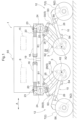
- a work vehicle includes a vehicle body 1 substantially in the form of a rectangular-shaped frame for supporting the entire vehicle, a plurality (specifically four sets) of traveling devices 2, a plurality of idle wheels 3 provided in correspondence with the plurality of traveling devices 2, a plurality of bending link mechanisms 10 (an example of an articulated link mechanism, an example of a body support portion), a plurality of hydraulic drive type driving mechanisms 5 serving as driving operational portions capable of variably operating the bending link mechanisms 10, and a plurality of working oil supply devices 6 for supplying working oil to the driving mechanisms 5 (an example of driving operational portion).
- Each one of the plurality of traveling devices 2 includes a wheel 7 supported to be rotatable about a horizontal axis and a hydraulic motor 9 mounted within a shaft support portion 8 of the wheel 7. In operation, each traveling device 2 is capable of rotatably driving each corresponding wheel 7 by activating the hydraulic motor 9.
- this direction in defining a front/rear direction of the vehicle body, this direction is defined along the traveling direction of the vehicle body.
- this direction In defining a left/right direction of the vehicle body, this direction is defined as seen along the vehicle body traveling (advancing) direction.
- the direction denoted with mark (A) in Fig. 1 is the vehicle body front/rear direction
- the direction denoted with mark (B) in Fig. 2 is the vehicle body left/right direction.
- the driving mechanism 5 is capable of changing the posture of each of the plurality of bending link mechanisms 10 independently.
- the idle wheel 3 is freely rotatably supported to an intermediate bending portion 11 (see Fig. 4 ) of each of the plurality of bending link mechanisms 10.
- one traveling device 2 and one idle wheel 3 corresponding to this traveling device 2 together constitute one set of "traveling functional portion 12".
- the one set of traveling functional portion 12 is supported to be changeable in its posture by one bending link mechanism 10.
- total of four sets of traveling functional portions 12 are mounted on the front and rear opposed sides of the vehicle body 1, one pair each on the left and right sides. Therefore, the bending link mechanism 10, the traveling device 2 and the idle wheel 3 respectively are provided one pair on the left and right sides on the front and rear opposed sides of the vehicle body 1.
- the vehicle body 1 includes a rectangular-shaped frame 13 configured to surround the entire circumference of the vehicle body 1 and to support this vehicle body 1 entirely.
- the working oil supply device 6 is supported as being accommodated in the inside of the vehicle body 1.
- the working oil supply device 6 includes a hydraulic pump driven by an engine mounted on the vehicle for delivering working oil to the driving mechanism 5, a plurality of hydraulic control valves for controlling the working oil delivered from the hydraulic pump to the driving mechanism 5, a working oil tank, etc. and caries out feeding/discharging of the working oil to/from the driving mechanism 5 or adjustment of its flow rate.
- control device 15 for controlling operations of the working oil supply devices 6. Though these control operations by the control device 15 will not be detailed herein, based on control information inputted via an unillustrated manual input device or control information set and stored in advance, the feeding states of the working oil to the driving mechanisms 5 and the hydraulic motors 9 are controlled.
- the plurality (specifically four sets) traveling devices 2 are supported to be elevated/lowered independently relative to the vehicle body 1 via the bending link mechanisms 10.
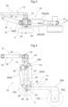
- Each bending mechanism 10 is supported to the vehicle body to be changeable in its orientation about a vertical axis by a turning mechanism 16.
- the bending link mechanism 10 is supported to the support frame 13 to be pivotable about a vertical axis Y via the turning mechanism 16.
- the turning mechanism 16 includes a vehicle body side support portion 17 (see Fig. 3 and Fig. 4 ) which is connected to the support frame 13 and pivotally supports the bending link mechanism 10, and a turning operation hydraulic cylinder 18 (to be referred to as a "turning cylinder 18" hereinafter) for turning the bending link mechanism 10.
- the vehicle body side support portion 17 includes connecting members 20 engageable with a pair of upper and lower angular cylindrical front/rear oriented frame bodies 17 provided at lateral side portions of the support frame 13 for clamping these frame bodies 17 from the lateral outer side and detachably bolt-connected to each other, an outer side pivot bracket 21 disposed at an outer side portion in the vehicle body front/rear direction of the connecting members 20, an inner side pivot bracket 22 disposed at an inner side portion in the vehicle body front/rear direction of the connecting members 20, and a vertically oriented pivot support shaft 23 supported to the outer side pivot bracket 21, whereby the vehicle body side support portion 17 supports the bending link mechanism 10 with allowing its pivotal movement about the axis Y of the pivot support shaft 23.
- the bending link mechanism 10 includes a base end portion 24 supported to the vehicle body side support portion 17 with its vertically position fixed and being pivotable about the vertical axis Y, a first link 25 having one end portion thereof supported to a lower portion of the base end portion 24 to be pivotable about a horizontal axis Xl, and a second link 26 having one end portion thereof supported to the other end portion of the first link 25 to be pivotable about a horizontal axis X2 and having the other end portion thereof supported to the traveling device 2.
- the base end portion 24 is provided in the form of a rectangular-shaped frame, and at a position offset to the vehicle body lateral width inner side, the base end portion 24 is supported to the outer side pivot bracket 21 of the vehicle body side support portion 17 to be pivotable about the vertical axis Y via the pivot support shaft 23.
- the turning cylinder 18 has its one end potion pivotally connected to the inner side pivot bracket 22 and has its outer end portion pivotally connected at a laterally offset position to the pivot support shaft 23 of the base end portion 24.
- a support shaft 27 provided on one end side of the first link 25 is pivotally supported, and the first link 25 is connected to a lower portion of the base end portion 24 to be pivotable about the axis of the support shaft 27.
- the first link 25 includes a base end side arm portion 25b and an other end side arm portion 25a. At one end side portion of the first link 25, there is integrally formed the base end side arm portion 25b extending obliquely upper outwards. At the other end side portion of the first link 25, there is integrally formed the other end side arm portion 25a extending obliquely upper outwards.
- the second link 26 is formed bifurcated as seen in the plan view, with a pair of left and right band-plate like plate bodies 26a, 26b.
- the connecting portion of the second link 26 to the first link 25 is separated with a spacing provided by the pair of plate bodies 26a, 26b.
- a connecting support shaft 28 to be connected to the first link 25 is pivotally supported.
- the traveling device 2 is supported. As shown in Fig.
- the driving mechanism 5 For each one of the plurality (four sets) of bending link mechanisms 10, the driving mechanism 5 is provided. As shown in Fig. 1 and Fig. 4 , the driving mechanism 5 includes a first hydraulic cylinder 29 capable of changing the pivotal posture of the first link 25 relative to the vehicle body 1 and a second hydraulic cylinder 30 capable of changing the pivotal posture of the second link 26 relative to the first link 25. The first hydraulic cylinder 29 and the second hydraulic cylinder 30 are disposed in concentration in the vicinity of the first link 25.
- the first link 25, the first hydraulic cylinder 29 and the second hydraulic cylinder 30 are arranged between the pair of plate bodies 26a, 26b of the second link 26.
- the first hydraulic cylinder 29 is located on the vehicle body front/rear direction inner side relative to the first link 25 to extend along the longitudinal direction of the first link 25.
- One end portion of the first hydraulic cylinder 29 is operably connected to a lower portion of the base end portion 24 via an arc-shaped first coupling member 31.
- the one end portion of the first hydraulic cylinder 29 is operably connected to a base end side portion of the first cylinder 25 via another second coupling member 32.
- the first coupling member 31 and the second coupling member 32 respectively have opposed end portions thereof pivotally connected to be pivotable relative to each other.
- the other end portion of the first hydraulic cylinder 29 is operably connected to the other end side arm portion 25a formed integral with the first link 25.
- the second hydraulic cylinder 30 is disposed on the opposite side to the first hydraulic cylinder 29, namely, on the vehicle body front/rear direction outer side relative to the first link 25 and substantially extends along the longitudinal direction of the first link 25.
- One end portion of the second hydraulic cylinder 30 is operably connected to the base end side arm portion 25b formed integral on the base end side of the first link 25.
- the other end portion of the second hydraulic cylinder 30 is operably connected to the arm portion 35 formed integral at the base end side portion of the second link 26 via a third coupling member 34.
- the other end portion of the second hydraulic cylinder 30 is operably connected also to the pivotal movement end side portion of the first link 25 via another fourth coupling member 36.
- the third coupling member 34 and the fourth coupling member 36 respectively have opposed end portions thereof pivotally connected to be pivotable relative to each other.
- the first hydraulic cylinder 29 When the first hydraulic cylinder 29 is extended or contracted with an operation of the second hydraulic cylinder 30 being stopped, the first link 25, the second link 26 and the traveling device 2 will respectively pivot together while maintaining the relative postures thereof, about the horizontal axis X1 where they are connected to the base end portion 24.
- the second hydraulic cylinder 30 When the second hydraulic cylinder 30 is extended or contracted with an operation of the first hydraulic cylinder 29 being stopped, the second link 26 and the traveling device 2 will pivot, with maintaining the posture of the first link 25 constant, together about the horizontal axis X2 at the connecting portion between the first link 25 and the second link 26.
- the idle wheel 3 is supported.
- the idle wheel 3 is configured as a wheel having an approximately same outside diameter as the wheel 7 of the traveling device 2.
- the connecting support shaft 28 which pivotally connects the first link 25 to the second link 26 is formed to extend to protrude on more vehicle body lateral width direction outer side than the second link 26.
- the idle wheel 3 is supported to be freely rotatable.
- the connecting support shaft 28 which pivotally connects the first link 25 to the second link 26 functions also as a pivot support shaft of the idle wheel 3, thus simplification of the arrangement through co-use of a component being sought for.
- the turning cylinder 18 has one end portion pivotally connected to the inner side pivot bracket 22 and has the other end portion pivotally connected to a position of the base end portion 24 offset laterally relative to the pivot support shaft 23.
- the bending link mechanism 10, the traveling device 2, the idle wheel 3 and the driving mechanism 5 respectively are supported altogether to the outer side pivot bracket 21 to be pivotable about the axis Y of the pivot shaft support 23. And, by extending/contracting the turning cylinder 18, the above members will be pivoted altogether. With this, it is possible to effect a turning operation from a straight traveling state in which the traveling device 2 is oriented along the front/rear direction to a left turning direction or a right turning direction by about 45 degrees, respectively.
- working oil is supplied respectively to the first hydraulic cylinder 29 and the second hydraulic cylinder 30 of each one of the plurality of bending link mechanism 10. Feeding and discharging of the working oil are effected by the hydraulic control valve, so that the first hydraulic cylinder 29 and the second hydraulic cylinder 30 can be extended/contracted.
- This hydraulic control valve is controlled by the control device 15.
- the hydraulic control valve corresponding to the hydraulic motor 9, the rotational speed of the hydraulic motor 9, namely, of the wheel 7 can be changed.
- the hydraulic control valve is controlled by the control device 15 based on e.g. control information inputted by a manual operation or preset and stored control information, etc.
- this work vehicle includes various kinds of sensors.
- the work vehicle includes a first cap-side pressure sensor S1 and a first head-side (counter-cap side) pressure sensor S2 which are provided in the first hydraulic cylinder 29, and a second cap-side pressure sensor S3 and a second head-side (counter-cap side) pressure sensor S4 which are provided in the second hydraulic cylinder 30.
- the firster cap-side pressure sensor S1 detects an oil pressure of a cap-side chamber of the first hydraulic cylinder 29.
- the first head-side pressure sensor S2 detects an oil pressure of a head-side chamber of the first hydraulic cylinder 29.
- the second cap-side pressure sensor S3 detects an oil pressure of a cap-side chamber of the second hydraulic cylinder 30.
- the second head-side pressure sensor S4 detects an oil pressure of a head-side chamber of the second hydraulic cylinder 30. Further, though not shown, the above-described hydraulic cylinders 18, 29, 30 respectively incorporates a stroke sensor capable of detecting an extension/contraction stroke amount, thus feeding back an operational state to the control device 15.
- the attaching positions of the respective pressure sensors S1, S2, S3, S4 are not limited to the positions described above. It suffices for the respective pressure sensors S1, S2, S3, S4 to be capable of detecting (estimating) an oil pressure in the cap-side chamber or the head-side chamber, and so these sensors may be disposed within pipes extending from the valve mechanism to the cap-side chamber or the head-side chamber corresponding thereto.
- a pressure difference between the cap-side chamber and the head-side chamber of the second hydraulic cylinder 30 is obtained and from this pressure difference, a cylinder propelling force for the second hydraulic cylinder 30 will be calculated, similarly for the first hydraulic cylinder 29.
- the vehicle body 1 mounts an acceleration sensor S5 which can be comprised of e.g. a three-axis acceleration sensor. Based on a detection result of this acceleration sensor S5, a front/rear, left/right tilt of the vehicle body 1 is detected and based on the result of this detection, the posture of the vehicle body 1 is controlled. Namely, supplies of the working oil to the respective first hydraulic cylinder 29 and the respective second hydraulic cylinder 30 will be controlled such that the posture of the vehicle body 1 may become a target posture.
- an acceleration sensor S5 which can be comprised of e.g. a three-axis acceleration sensor.
- the traveling device 2 includes a rotation sensor S6 for detecting a rotational speed of the wheel 7. Based on a rotational speed of the wheel 7 calculated by the rotation sensor S6, the supply of the working oil to the hydraulic motor 9 is controlled so that the rotational speed of the wheel 7 may become a target speed.
- the work vehicle of this embodiment is configured such that the traveling device 2 is supported via the bending link mechanism 10 and also that the posture of the bending link mechanism 10 is changed by the hydraulic cylinders 29, 30 as the hydraulic drive type driving mechanism 5 and moreover that the traveling drive is carried out by means of a hydraulic motor. Therefore, the work vehicle is suitable for an agricultural work as being affected little by water or fine dust, etc.
- the traveling mode can be a four-wheel traveling mode in which all of the four traveling devices 2 (specifically the wheels 7) are placed in contact with the ground surface and also all of the four idle wheels 3 are set afloat the ground surface.
- the traveling mode can be a four-wheel traveling mode in which all of the four traveling devices 2 (specifically the wheels 7) are placed in contact with the ground surface and also all of the four idle wheels 3 are set afloat the ground surface.
- the traveling mode can be a four-wheel traveling mode in which all of the four traveling devices 2 (specifically the wheels 7) are placed in contact with the ground surface and also all of the four idle wheels 3 are set afloat the ground surface.
- the traveling mode can be a two-wheel traveling mode in which the traveling device 2 (wheel 7) located on one side in the vehicle body front/rear direction is placed in contact with the ground surface and the idle wheel 3 corresponding to this traveling device 2 (wheel 7) is set afloat the ground surface and also the traveling device 2 (wheel 7) located on the other side in the vehicle body front/rear direction is set afloat the ground surface and the idle wheel 3 corresponding to that traveling device 2 (wheel 7) is placed on contact with the ground surface.
- the two wheel traveling state can be also a state in which the relationship between the traveling device 2 (wheel 7) and the idle wheel 3 is reversed in the vehicle body front/rear direction. That is, as shown in Fig. 11 , it can be a state in which the traveling device 2 (wheel 7) located on one side in the vehicle body front/rear direction is placed in contact with the ground surface and the idle wheel 3 corresponding to this traveling device 2 (wheel 7) is set afloat the ground surface and also the traveling device 2 (wheel 7) located on the other side in the vehicle body front/rear direction is set afloat the ground surface and the idle wheel 3 corresponding to this traveling device 2 is placed in contact with the ground surface.
- the bending link mechanism 10 can be configured in each one of the four sets of traveling functional portions 12 to be switchable between a traveling state in which the traveling device 2 (wheel 7) is placed in contact with the ground surface and the idle wheel 3 corresponding thereto is set afloat the ground surface; and a free moving state in which the idle wheel 3 is placed in contact with the ground surface and the traveling device 2 (wheel 7) corresponding thereto is set afloat the ground surface.
- all of the four sets of traveling functional portions 12 are set to the traveling state.
- two sets of traveling functional portions 12 on one side in the vehicle body front/rear direction are set to the traveling state and two sets of the traveling functional portions 12 on the opposite side are set to the free traveling state.
- the driving mechanism 5 can be switched over between an "all traveling state” in which all of the four traveling functional portions 12 are set to the traveling state and the "partial traveling state” in which at least one of the fourth traveling functional portions 12 is set to the traveling state and the remaining others are set to the free moving state.
- the work vehicle in addition to the above-described traveling on a flat ground surface, the work vehicle can be used in following modes as "special" uses thereof.
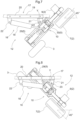
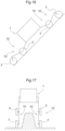
- the vehicle body 1 when all of the traveling devices 2 and the idle wheels 3 of the two sets of traveling functional portions 12 on one side in the vehicle body front/rear direction are placed in contact with the ground surface, the vehicle body 1 is greatly tilted to raise the other side thereof with using the bending link mechanisms 10 which support the two sets of traveling functional portions 12 on the other side in the vehicle body front/rear direction. And, when the vehicle body becomes tilted until a gravity center position W of the vehicle body 1 is located within a ground contacting width L defined by the two sets of traveling function portions 12 on the other side, the bending link mechanisms 10 supporting the two sets of traveling functional portions 12 on the other side can be extended largely to place the traveling devices 2 onto a ground surface which is located at a high place.
- the traveling devices 2 of the two sets of traveling functional portions 12 on the other side in the vehicle body front/rear direction an object M as a conveying subject will be clamped and then hoisted. With the object M being clamped, it is possible to travel and move with keeping the posture of the vehicle body by the two sets of traveling functional portions 12 on one side in the vehicle body front/rear direction, so that the object M can be conveyed.
- the postures of the bending link mechanisms 10 will be switched to the extended postures in which the traveling devices 2 and the idle wheels 3 are respectively located on more vehicle body front/rear direction outer side than the vehicle body front/rear direction outer end portions.
- the first links 25 and the second links 26 will be brought as close as possible to the horizontal posture, thereby to lower the height of the vehicle body 1 to a low position.
- the vehicle will travel while climbing up a slope face.
- the ground contacting width along the vehicle body front/rear direction is increased, so that even on a sloped face having a significant inclination, the vehicle can travel in a stable manner without toppling.
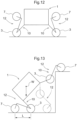
- All of the traveling devices 2 and the idle wheels 3 of three sets of traveling functional portions 12 of the total four sets of traveling functional portions 12 will be placed in contact with the ground surface, so as to support the vehicle body 1 on the ground surface in a stable manner.
- the bending link mechanism 10 supporting the remaining one traveling function portion 12 will be extended largely to allow each traveling device 2 to ride onto an upper face of a step, so that the vehicle can ride over the step, as shown in Fig. 13 for instance.
- the bending link mechanism 10 of each set of traveling functional portions 12 is extended, each set of traveling functional portions 12 will be moved to ride onto the upper face of a higher step, thereby to ride over the step.
- Fig. 13 illustrates a case of the high step, but the vehicle body 1 can ride over a step if it is low.
- the bending link mechanisms 10 will be extended largely, so as to elevate the vehicle body 1 far above the ground surface.
- a utility work can be carried out with keeping the vehicle body 1 striding across above a ridge.
- a chemical agent spraying a harvesting work from above the produce.
- control device 15 will control operations of the respective hydraulic cylinders 18, 29, 30 and the respective hydraulic motors 9, in a mode corresponding to instructed contents, based on the control information inputted by a manual operation or preset and stored control information, etc.
Landscapes
- Engineering & Computer Science (AREA)
- Mechanical Engineering (AREA)
- Chemical & Material Sciences (AREA)
- Combustion & Propulsion (AREA)
- Transportation (AREA)
- Robotics (AREA)
- Manipulator (AREA)
- Vehicle Body Suspensions (AREA)
- Agricultural Machines (AREA)
- Vehicle Cleaning, Maintenance, Repair, Refitting, And Outriggers (AREA)
Claims (9)
- Nutzfahrzeug, umfassend:eine Fahrzeugkarosserie (1);eine Vielzahl von Fahrvorrichtungen (2) zum Antreiben eines Fahrens;eine Vielzahl von gelenkigen Bindegliedmechanismen (10), die mindestens zwei oder mehrere Gelenke aufweisen, die die Vielzahl von Fahrvorrichtungen an der Fahrzeugkarosserie tragen, wobei die Vielzahl von Fahrvorrichtungen unabhängig voneinander angehoben/abgesenkt werden kann;einen Fahrmechanismus (5), der in der Lage ist, jeweilige Stellungen der Vielzahl von gelenkigen Bindegliedmechanismen (10) unabhängig voneinander zu ändern; undeine Vielzahl von Drehmechanismen (16), die konfiguriert sind, um die jeweilige Vielzahl der gelenkigen Bindegliedmechanismen an der Fahrzeugkarosserie zu tragen, wobei ermöglicht ist, dass die Bindegliedmechanismen in ihrer Ausrichtung um eine vertikale Achse veränderbar sind;dadurch gekennzeichnet, dass der Drehmechanismus (16) einen fahrzeugseitigen Tragabschnitt (17), der abnehmbar mit einem Rahmen der Fahrzeugkarosserie (1) verbunden ist, und einen Hydraulikzylinder (18) für einen Drehvorgang zum Ändern einer Ausrichtung des gelenkigen Bindegliedmechanismus (10) um die vertikale Achse in Bezug auf das fahrzeugseitige Tragelement beinhaltet;der Hydraulikzylinder einen ersten Endabschnitt, der mit einem Basisendabschnitt (24) des gelenkigen Bindegliedmechanismus (10) verbunden ist, und einen zweiten Endabschnitt, der mit dem fahrzeugseitigen Tragabschnitt (17) verbunden ist, aufweist; undder Basisendabschnitt (24) des gelenkigen Bindegliedmechanismus (10) von dem fahrzeugseitigen Tragabschnitt (17) des Drehmechanismus (16) getragen wird, um um die vertikale Achse schwenkbar zu sein.
- Nutzfahrzeug nach Anspruch 1, wobei:
der gelenkige Bindegliedmechanismus (10) ein erstes Bindegliedglied (25), dessen einer Endabschnitt schwenkbar mit dem Basisendabschnitt (24) verbunden ist, um um eine horizontale Achse schwenkbar zu sein, und ein zweites Bindegliedglied (26), dessen einer Endabschnitt schwenkbar mit dem anderen Endabschnitt des ersten Bindegliedglieds verbunden ist, um um eine horizontale Achse schwenkbar zu sein, und dessen anderer Endabschnitt die Fahrvorrichtung (2) trägt, beinhaltet. - Nutzfahrzeug nach Anspruch 2, wobei:
der Fahrmechanismus (5) einen ersten Hydraulikzylinder (29), der in der Lage ist, die Schwenkstellung des ersten Gelenks (25) in Bezug auf die Fahrzeugkarosserie (1) zu verändern, und einen zweiten Hydraulikzylinder (30), der in der Lage ist, die Schwenkstellung des zweiten Bindeglieds (26) in Bezug auf das erste Bindeglied zu verändern, beinhaltet. - Nutzfahrzeug nach Anspruch 2 oder 3, wobei:ein Freilaufrad (3) an einem Verbindungsabschnitt zwischen dem ersten Bindeglied (25) und dem zweiten Bindeglied (26) getragen wird; unddie Fahrvorrichtung (2) und das Freilaufrad (3) in ihren Ausrichtungen gemeinsam um die vertikale Achse veränderbar sind.
- Nutzfahrzeug nach einem der Ansprüche 1-4, wobei:der gelenkige Bindegliedmechanismus (10) angeordnet ist, um sich an einer seitlicheren Außenseite als ein seitlicher äußerer Endabschnitt der Fahrzeugkarosserie (1) zu befinden; undder Drehmechanismus (16) gesehen in einer Draufsicht angeordnet ist, um sich zwischen der Fahrzeugkarosserie (1) und dem gelenkigen Bindegliedmechanismus (10) zu befinden.
- Nutzfahrzeug nach einem der Ansprüche 1-5, wobei:
der Drehmechanismus (16) in einem Zustand bereitgestellt ist, in dem er sich gesehen in einer Seitenansicht weiter oben befindet als der gelenkige Bindegliedmechanismus (10). - Nutzfahrzeug, umfassend:eine Fahrzeugkarosserie (1);eine Vielzahl von Fahrfunktionsabschnitten (12), die als ein Paar links und rechts an jeweiligen vorderen/hinteren gegenüberliegenden Seitenabschnitten der Fahrzeugkarosserie (1) bereitgestellt sind, wobei die Fahrfunktionsabschnitte zum Fahren antreibbar sind;einen Fahrzeugkarosserietragabschnitt (10) zum Tragen der beweglichen Funktionsabschnitte (12), die jeweils Änderungen von Höhenpositionen davon in Bezug auf die Fahrzeugkarosserie ermöglichen und auch ein Aufrechterhalten der Haltung der Fahrzeugkarosserie ermöglichen; undeinen Fahrbetriebsabschnitt (5), der funktionsfähig ist, um den Fahrtragabschnitt zu ändern;dadurch gekennzeichnet, dass die Vielzahl von Fahrfunktionsabschnitten (12) jeweils ein Rad (7) für Fahrantrieb und ein dem Rad (7) entsprechendes Leerlaufrad (3) umfasst;der Fahrfunktionsabschnitt (12) angeordnet ist, sodass, wenn das Rad (7) und das Freilaufrad (3) beide in Kontakt mit der Bodenoberfläche kommen, die Fahrzeugkarosserie (1) mit einer sich zwischen dem Rad und dem Freilaufrad erstreckenden vorderen/hinteren Breite getragen wird;der Fahrzeugkarosserietragabschnitt einen biegenden Gelenkmechanismus (10) umfasst, wobei der biegende Gelenkmechanismus ein erstes Bindeglied (25), dessen einer Endabschnitt um eine horizontale Achse schwenkbar an der Fahrzeugkarosserie (1) getragen wird, und ein zweites Bindeglied (26), dessen einer Endabschnitt um eine horizontale Achse schwenkbar an dem anderen Endabschnitt des ersten Bindeglieds getragen wird, beinhaltet;das Rad (7) an dem anderen Endabschnitt des zweiten Bindeglieds (26) getragen wird;das Freilaufrad (3) an einem Verbindungsabschnitt zwischen dem ersten Bindeglied (25) und dem zweiten Bindeglied (26) getragen wird;die Fahrfunktionsabschnitte (12) und der Fahrzeugkarosserietragabschnitt (10) an der Fahrzeugkarosserie (1) getragen werden, um um eine vertikale Achse drehbar zu sein; undwenn die Fahrfunktionsabschnitte (12) auf der linken und rechten gegenüberliegenden Seite, die sich auf der Fahrzeugvorderseite befinden, und die Fahrfunktionsabschnitte (12) auf der linken und rechten Seite, die sich auf der Fahrzeugrückseite befinden, in Kontakt mit der Bodenoberfläche sind, das Nutzfahrzeug fahrfähig ist und das Rad (7) und das Leerlaufrad (3) zusammen um die vertikale Achse drehbar sind; undwenn einer der Fahrfunktionsabschnitte (12) auf der linken und rechten gegenüberliegenden Seite, die sich auf der Fahrzeugvorderseite befinden, und die Fahrfunktionsabschnitte (12) auf der linken und rechten Seite, die sich auf der Fahrzeugrückseite befinden, in Kontakt mit der Bodenoberfläche gebracht werden, um die Haltung der Fahrzeugkarosserie (1) aufrechtzuerhalten, die anderen davon von der Bodenoberfläche abgehoben und näher zueinander gedreht werden, um ein Objekt dazwischen einzuspannen.
- Nutzfahrzeug nach Anspruch 7, ferner umfassend:
eine Vielzahl von Drehmechanismen (16), die konfiguriert sind, um die jeweilige Vielzahl von Fahrzeugkarosserietragabschnitten (10) an der Fahrzeugkarosserie (1) zu tragen, um um eine vertikale Achse drehbar zu sein. - Nutzfahrzeug nach Anspruch 8, wobei:der Antriebsfunktionsabschnitt (5) einen ersten Hydraulikzylinder (29), der in der Lage ist, die Schwenkstellung des ersten Bindeglieds (25) in Bezug auf die Fahrzeugkarosserie (1) zu verändern, und einen zweiten Hydraulikzylinder (30), der in der Lage ist, die Schwenkstellung des zweiten Bindeglieds (26) in Bezug auf das erste Bindeglied zu verändern, beinhaltet; undder Drehmechanismus (16) einen Hydraulikzylinder (18) für einen Drehvorgang zum Ändern der Ausrichtung des biegenden Gelenkmechanismus um die vertikale Achse beinhaltet.
Applications Claiming Priority (3)
| Application Number | Priority Date | Filing Date | Title |
|---|---|---|---|
| JP2017066389A JP6745750B2 (ja) | 2017-03-29 | 2017-03-29 | 作業車 |
| JP2017066390A JP6745751B2 (ja) | 2017-03-29 | 2017-03-29 | 作業車 |
| PCT/JP2018/012709 WO2018181459A1 (ja) | 2017-03-29 | 2018-03-28 | 作業車 |
Publications (3)
| Publication Number | Publication Date |
|---|---|
| EP3604091A1 EP3604091A1 (de) | 2020-02-05 |
| EP3604091A4 EP3604091A4 (de) | 2020-12-23 |
| EP3604091B1 true EP3604091B1 (de) | 2024-08-21 |
Family
ID=63676223
Family Applications (1)
| Application Number | Title | Priority Date | Filing Date |
|---|---|---|---|
| EP18777605.9A Active EP3604091B1 (de) | 2017-03-29 | 2018-03-28 | Nutzfahrzeug |
Country Status (4)
| Country | Link |
|---|---|
| US (1) | US11524735B2 (de) |
| EP (1) | EP3604091B1 (de) |
| CN (1) | CN110461690A (de) |
| WO (1) | WO2018181459A1 (de) |
Families Citing this family (21)
| Publication number | Priority date | Publication date | Assignee | Title |
|---|---|---|---|---|
| CN109923032B (zh) * | 2016-12-22 | 2022-06-03 | 株式会社久保田 | 作业车 |
| EP3604092B1 (de) * | 2017-03-29 | 2024-08-21 | Kubota Corporation | Nutzfahrzeug |
| EP3733488B1 (de) * | 2017-12-25 | 2024-12-18 | Kubota Corporation | Nutzfahrzeug |
| CN112118996A (zh) * | 2018-05-16 | 2020-12-22 | 三菱电机株式会社 | 移动台车 |
| BE1026400B1 (nl) * | 2018-06-20 | 2020-01-30 | Cnh Ind Belgium Nv | Asopstelling voor een landbouwbalenpers |
| US11760378B1 (en) * | 2018-11-19 | 2023-09-19 | Zhengxu He | Type of vehicles |
| US11579621B2 (en) * | 2018-11-19 | 2023-02-14 | Zhengxu He | Automated restaurant |
| CN110270973B (zh) * | 2018-12-29 | 2022-11-11 | 杭州慧盈智能科技有限公司 | 一种仓储物流机器人及其工作方法、自动更换电池方法 |
| CN109557173B (zh) * | 2019-01-17 | 2023-12-22 | 中国石油大学(北京) | 无损检测装置 |
| US12227054B2 (en) * | 2019-05-21 | 2025-02-18 | Ree Automotive Ltd | Wheel suspension system with mobile steering axis |
| JP7321910B2 (ja) | 2019-12-02 | 2023-08-07 | 株式会社クボタ | 農業用ロボット |
| US11975585B2 (en) * | 2019-12-05 | 2024-05-07 | Lockheed Martin Corporation | Systems and methods for detecting characteristics of a multi-oriented surface |
| WO2021175042A1 (zh) * | 2020-03-02 | 2021-09-10 | 大陆智源科技(北京)有限公司 | 悬挂装置、悬挂减振装置及六轮仿生底盘 |
| CN113353167B (zh) * | 2020-03-04 | 2024-11-12 | 徐丽华 | 一种行走装置 |
| JP7412323B2 (ja) * | 2020-12-11 | 2024-01-12 | 株式会社クボタ | 作業車 |
| JP7450525B2 (ja) * | 2020-12-11 | 2024-03-15 | 株式会社クボタ | 作業車 |
| CN112793680B (zh) * | 2021-02-04 | 2025-10-17 | 宁波新宏液压有限公司 | 一种可越障的工业运送机器人 |
| CN113401240B (zh) * | 2021-08-04 | 2022-05-24 | 中国人民解放军国防科技大学 | 轮腿复合式轮系系统、行走装置及行走方法 |
| WO2023180687A1 (en) * | 2022-03-23 | 2023-09-28 | Bae Systems Plc | Suspension system |
| WO2025004639A1 (ja) * | 2023-06-28 | 2025-01-02 | 株式会社クボタ | 作業車及び、作業車システム |
| KR20250073953A (ko) * | 2023-11-20 | 2025-05-27 | 현대자동차주식회사 | 바퀴의 링크 구조 |
Family Cites Families (8)
| Publication number | Priority date | Publication date | Assignee | Title |
|---|---|---|---|---|
| US4558758A (en) * | 1983-12-02 | 1985-12-17 | Erwin Littman | Prime mover |
| JPH09142347A (ja) | 1995-11-24 | 1997-06-03 | Mitsubishi Heavy Ind Ltd | 不整地移動装置 |
| JP2005131756A (ja) * | 2003-10-31 | 2005-05-26 | Victor Co Of Japan Ltd | 移動ロボット |
| JP4797775B2 (ja) * | 2006-04-24 | 2011-10-19 | 株式会社日立製作所 | 2足型移動機構 |
| JP2009096335A (ja) * | 2007-10-17 | 2009-05-07 | Nsk Ltd | 脚型ロボット |
| CN104773042B (zh) * | 2015-04-03 | 2017-01-18 | 西北工业大学 | 一种具有可变形结构的水陆两栖机器人 |
| CN105966488A (zh) * | 2016-06-02 | 2016-09-28 | 北京航空航天大学 | 一种六轮腿移动操作机器人实验平台 |
| CN106184456A (zh) * | 2016-07-08 | 2016-12-07 | 上海大学 | 一种主体结构可多级伸缩的轮腿式机器人 |
-
2018
- 2018-03-28 WO PCT/JP2018/012709 patent/WO2018181459A1/ja not_active Ceased
- 2018-03-28 EP EP18777605.9A patent/EP3604091B1/de active Active
- 2018-03-28 CN CN201880023106.XA patent/CN110461690A/zh active Pending
- 2018-03-28 US US16/496,012 patent/US11524735B2/en active Active
Also Published As
| Publication number | Publication date |
|---|---|
| CN110461690A (zh) | 2019-11-15 |
| US11524735B2 (en) | 2022-12-13 |
| US20200017152A1 (en) | 2020-01-16 |
| WO2018181459A1 (ja) | 2018-10-04 |
| EP3604091A1 (de) | 2020-02-05 |
| EP3604091A4 (de) | 2020-12-23 |
Similar Documents
| Publication | Publication Date | Title |
|---|---|---|
| EP3604091B1 (de) | Nutzfahrzeug | |
| EP3604092B1 (de) | Nutzfahrzeug | |
| EP3733488B1 (de) | Nutzfahrzeug | |
| US11767071B2 (en) | Work vehicle | |
| US11498632B2 (en) | Work vehicle | |
| JP7117989B2 (ja) | 作業車 | |
| JP6758278B2 (ja) | 作業車 | |
| JP6899801B2 (ja) | 作業車 | |
| JP6745750B2 (ja) | 作業車 | |
| JP2020001440A (ja) | 作業車 | |
| JP6758277B2 (ja) | 作業車 | |
| JP6937725B2 (ja) | 作業車 | |
| WO2019131573A1 (ja) | 作業車 | |
| JP2020001441A (ja) | 作業車 | |
| JP6745751B2 (ja) | 作業車 | |
| JP6739387B2 (ja) | 作業車 | |
| JP6701112B2 (ja) | 作業車 | |
| JP2018167690A (ja) | 作業車 | |
| JP2023092156A (ja) | 作業車 | |
| JPH09263149A (ja) | 作業用車輌の走行装置 |
Legal Events
| Date | Code | Title | Description |
|---|---|---|---|
| STAA | Information on the status of an ep patent application or granted ep patent |
Free format text: STATUS: THE INTERNATIONAL PUBLICATION HAS BEEN MADE |
|
| PUAI | Public reference made under article 153(3) epc to a published international application that has entered the european phase |
Free format text: ORIGINAL CODE: 0009012 |
|
| STAA | Information on the status of an ep patent application or granted ep patent |
Free format text: STATUS: REQUEST FOR EXAMINATION WAS MADE |
|
| 17P | Request for examination filed |
Effective date: 20191002 |
|
| AK | Designated contracting states |
Kind code of ref document: A1 Designated state(s): AL AT BE BG CH CY CZ DE DK EE ES FI FR GB GR HR HU IE IS IT LI LT LU LV MC MK MT NL NO PL PT RO RS SE SI SK SM TR |
|
| AX | Request for extension of the european patent |
Extension state: BA ME |
|
| DAV | Request for validation of the european patent (deleted) | ||
| DAX | Request for extension of the european patent (deleted) | ||
| A4 | Supplementary search report drawn up and despatched |
Effective date: 20201119 |
|
| RIC1 | Information provided on ipc code assigned before grant |
Ipc: B62D 57/02 20060101ALI20201113BHEP Ipc: B62D 61/12 20060101AFI20201113BHEP Ipc: B62D 15/00 20060101ALI20201113BHEP Ipc: B60G 3/20 20060101ALI20201113BHEP Ipc: B25J 5/00 20060101ALI20201113BHEP Ipc: B62D 7/15 20060101ALI20201113BHEP Ipc: B62D 61/10 20060101ALI20201113BHEP |
|
| GRAP | Despatch of communication of intention to grant a patent |
Free format text: ORIGINAL CODE: EPIDOSNIGR1 |
|
| STAA | Information on the status of an ep patent application or granted ep patent |
Free format text: STATUS: GRANT OF PATENT IS INTENDED |
|
| INTG | Intention to grant announced |
Effective date: 20240318 |
|
| GRAS | Grant fee paid |
Free format text: ORIGINAL CODE: EPIDOSNIGR3 |
|
| GRAA | (expected) grant |
Free format text: ORIGINAL CODE: 0009210 |
|
| STAA | Information on the status of an ep patent application or granted ep patent |
Free format text: STATUS: THE PATENT HAS BEEN GRANTED |
|
| AK | Designated contracting states |
Kind code of ref document: B1 Designated state(s): AL AT BE BG CH CY CZ DE DK EE ES FI FR GB GR HR HU IE IS IT LI LT LU LV MC MK MT NL NO PL PT RO RS SE SI SK SM TR |
|
| REG | Reference to a national code |
Ref country code: GB Ref legal event code: FG4D |
|
| REG | Reference to a national code |
Ref country code: CH Ref legal event code: EP |
|
| REG | Reference to a national code |
Ref country code: IE Ref legal event code: FG4D |
|
| REG | Reference to a national code |
Ref country code: DE Ref legal event code: R096 Ref document number: 602018073370 Country of ref document: DE |
|
| REG | Reference to a national code |
Ref country code: LT Ref legal event code: MG9D |
|
| REG | Reference to a national code |
Ref country code: NL Ref legal event code: MP Effective date: 20240821 |
|
| PG25 | Lapsed in a contracting state [announced via postgrant information from national office to epo] |
Ref country code: NO Free format text: LAPSE BECAUSE OF FAILURE TO SUBMIT A TRANSLATION OF THE DESCRIPTION OR TO PAY THE FEE WITHIN THE PRESCRIBED TIME-LIMIT Effective date: 20241121 |
|
| REG | Reference to a national code |
Ref country code: AT Ref legal event code: MK05 Ref document number: 1715260 Country of ref document: AT Kind code of ref document: T Effective date: 20240821 |
|
| PG25 | Lapsed in a contracting state [announced via postgrant information from national office to epo] |
Ref country code: NL Free format text: LAPSE BECAUSE OF FAILURE TO SUBMIT A TRANSLATION OF THE DESCRIPTION OR TO PAY THE FEE WITHIN THE PRESCRIBED TIME-LIMIT Effective date: 20240821 Ref country code: GR Free format text: LAPSE BECAUSE OF FAILURE TO SUBMIT A TRANSLATION OF THE DESCRIPTION OR TO PAY THE FEE WITHIN THE PRESCRIBED TIME-LIMIT Effective date: 20241122 Ref country code: PT Free format text: LAPSE BECAUSE OF FAILURE TO SUBMIT A TRANSLATION OF THE DESCRIPTION OR TO PAY THE FEE WITHIN THE PRESCRIBED TIME-LIMIT Effective date: 20241223 Ref country code: FI Free format text: LAPSE BECAUSE OF FAILURE TO SUBMIT A TRANSLATION OF THE DESCRIPTION OR TO PAY THE FEE WITHIN THE PRESCRIBED TIME-LIMIT Effective date: 20240821 Ref country code: PL Free format text: LAPSE BECAUSE OF FAILURE TO SUBMIT A TRANSLATION OF THE DESCRIPTION OR TO PAY THE FEE WITHIN THE PRESCRIBED TIME-LIMIT Effective date: 20240821 |
|
| PG25 | Lapsed in a contracting state [announced via postgrant information from national office to epo] |
Ref country code: BG Free format text: LAPSE BECAUSE OF FAILURE TO SUBMIT A TRANSLATION OF THE DESCRIPTION OR TO PAY THE FEE WITHIN THE PRESCRIBED TIME-LIMIT Effective date: 20240821 |
|
| PG25 | Lapsed in a contracting state [announced via postgrant information from national office to epo] |
Ref country code: LV Free format text: LAPSE BECAUSE OF FAILURE TO SUBMIT A TRANSLATION OF THE DESCRIPTION OR TO PAY THE FEE WITHIN THE PRESCRIBED TIME-LIMIT Effective date: 20240821 |
|
| PG25 | Lapsed in a contracting state [announced via postgrant information from national office to epo] |
Ref country code: AT Free format text: LAPSE BECAUSE OF FAILURE TO SUBMIT A TRANSLATION OF THE DESCRIPTION OR TO PAY THE FEE WITHIN THE PRESCRIBED TIME-LIMIT Effective date: 20240821 Ref country code: IS Free format text: LAPSE BECAUSE OF FAILURE TO SUBMIT A TRANSLATION OF THE DESCRIPTION OR TO PAY THE FEE WITHIN THE PRESCRIBED TIME-LIMIT Effective date: 20241221 |
|
| PG25 | Lapsed in a contracting state [announced via postgrant information from national office to epo] |
Ref country code: HR Free format text: LAPSE BECAUSE OF FAILURE TO SUBMIT A TRANSLATION OF THE DESCRIPTION OR TO PAY THE FEE WITHIN THE PRESCRIBED TIME-LIMIT Effective date: 20240821 |
|
| PG25 | Lapsed in a contracting state [announced via postgrant information from national office to epo] |
Ref country code: ES Free format text: LAPSE BECAUSE OF FAILURE TO SUBMIT A TRANSLATION OF THE DESCRIPTION OR TO PAY THE FEE WITHIN THE PRESCRIBED TIME-LIMIT Effective date: 20240821 Ref country code: RS Free format text: LAPSE BECAUSE OF FAILURE TO SUBMIT A TRANSLATION OF THE DESCRIPTION OR TO PAY THE FEE WITHIN THE PRESCRIBED TIME-LIMIT Effective date: 20241121 |
|
| PG25 | Lapsed in a contracting state [announced via postgrant information from national office to epo] |
Ref country code: RS Free format text: LAPSE BECAUSE OF FAILURE TO SUBMIT A TRANSLATION OF THE DESCRIPTION OR TO PAY THE FEE WITHIN THE PRESCRIBED TIME-LIMIT Effective date: 20241121 Ref country code: PT Free format text: LAPSE BECAUSE OF FAILURE TO SUBMIT A TRANSLATION OF THE DESCRIPTION OR TO PAY THE FEE WITHIN THE PRESCRIBED TIME-LIMIT Effective date: 20241223 Ref country code: PL Free format text: LAPSE BECAUSE OF FAILURE TO SUBMIT A TRANSLATION OF THE DESCRIPTION OR TO PAY THE FEE WITHIN THE PRESCRIBED TIME-LIMIT Effective date: 20240821 Ref country code: NO Free format text: LAPSE BECAUSE OF FAILURE TO SUBMIT A TRANSLATION OF THE DESCRIPTION OR TO PAY THE FEE WITHIN THE PRESCRIBED TIME-LIMIT Effective date: 20241121 Ref country code: NL Free format text: LAPSE BECAUSE OF FAILURE TO SUBMIT A TRANSLATION OF THE DESCRIPTION OR TO PAY THE FEE WITHIN THE PRESCRIBED TIME-LIMIT Effective date: 20240821 Ref country code: LV Free format text: LAPSE BECAUSE OF FAILURE TO SUBMIT A TRANSLATION OF THE DESCRIPTION OR TO PAY THE FEE WITHIN THE PRESCRIBED TIME-LIMIT Effective date: 20240821 Ref country code: IS Free format text: LAPSE BECAUSE OF FAILURE TO SUBMIT A TRANSLATION OF THE DESCRIPTION OR TO PAY THE FEE WITHIN THE PRESCRIBED TIME-LIMIT Effective date: 20241221 Ref country code: HR Free format text: LAPSE BECAUSE OF FAILURE TO SUBMIT A TRANSLATION OF THE DESCRIPTION OR TO PAY THE FEE WITHIN THE PRESCRIBED TIME-LIMIT Effective date: 20240821 Ref country code: GR Free format text: LAPSE BECAUSE OF FAILURE TO SUBMIT A TRANSLATION OF THE DESCRIPTION OR TO PAY THE FEE WITHIN THE PRESCRIBED TIME-LIMIT Effective date: 20241122 Ref country code: FI Free format text: LAPSE BECAUSE OF FAILURE TO SUBMIT A TRANSLATION OF THE DESCRIPTION OR TO PAY THE FEE WITHIN THE PRESCRIBED TIME-LIMIT Effective date: 20240821 Ref country code: ES Free format text: LAPSE BECAUSE OF FAILURE TO SUBMIT A TRANSLATION OF THE DESCRIPTION OR TO PAY THE FEE WITHIN THE PRESCRIBED TIME-LIMIT Effective date: 20240821 Ref country code: BG Free format text: LAPSE BECAUSE OF FAILURE TO SUBMIT A TRANSLATION OF THE DESCRIPTION OR TO PAY THE FEE WITHIN THE PRESCRIBED TIME-LIMIT Effective date: 20240821 Ref country code: AT Free format text: LAPSE BECAUSE OF FAILURE TO SUBMIT A TRANSLATION OF THE DESCRIPTION OR TO PAY THE FEE WITHIN THE PRESCRIBED TIME-LIMIT Effective date: 20240821 |
|
| PG25 | Lapsed in a contracting state [announced via postgrant information from national office to epo] |
Ref country code: DK Free format text: LAPSE BECAUSE OF FAILURE TO SUBMIT A TRANSLATION OF THE DESCRIPTION OR TO PAY THE FEE WITHIN THE PRESCRIBED TIME-LIMIT Effective date: 20240821 Ref country code: SM Free format text: LAPSE BECAUSE OF FAILURE TO SUBMIT A TRANSLATION OF THE DESCRIPTION OR TO PAY THE FEE WITHIN THE PRESCRIBED TIME-LIMIT Effective date: 20240821 Ref country code: RO Free format text: LAPSE BECAUSE OF FAILURE TO SUBMIT A TRANSLATION OF THE DESCRIPTION OR TO PAY THE FEE WITHIN THE PRESCRIBED TIME-LIMIT Effective date: 20240821 |
|
| PG25 | Lapsed in a contracting state [announced via postgrant information from national office to epo] |
Ref country code: EE Free format text: LAPSE BECAUSE OF FAILURE TO SUBMIT A TRANSLATION OF THE DESCRIPTION OR TO PAY THE FEE WITHIN THE PRESCRIBED TIME-LIMIT Effective date: 20240821 |
|
| PG25 | Lapsed in a contracting state [announced via postgrant information from national office to epo] |
Ref country code: CZ Free format text: LAPSE BECAUSE OF FAILURE TO SUBMIT A TRANSLATION OF THE DESCRIPTION OR TO PAY THE FEE WITHIN THE PRESCRIBED TIME-LIMIT Effective date: 20240821 |
|
| PG25 | Lapsed in a contracting state [announced via postgrant information from national office to epo] |
Ref country code: IT Free format text: LAPSE BECAUSE OF FAILURE TO SUBMIT A TRANSLATION OF THE DESCRIPTION OR TO PAY THE FEE WITHIN THE PRESCRIBED TIME-LIMIT Effective date: 20240821 Ref country code: SK Free format text: LAPSE BECAUSE OF FAILURE TO SUBMIT A TRANSLATION OF THE DESCRIPTION OR TO PAY THE FEE WITHIN THE PRESCRIBED TIME-LIMIT Effective date: 20240821 |
|
| REG | Reference to a national code |
Ref country code: DE Ref legal event code: R097 Ref document number: 602018073370 Country of ref document: DE |
|
| PLBE | No opposition filed within time limit |
Free format text: ORIGINAL CODE: 0009261 |
|
| STAA | Information on the status of an ep patent application or granted ep patent |
Free format text: STATUS: NO OPPOSITION FILED WITHIN TIME LIMIT |
|
| 26N | No opposition filed |
Effective date: 20250522 |
|
| PG25 | Lapsed in a contracting state [announced via postgrant information from national office to epo] |
Ref country code: SE Free format text: LAPSE BECAUSE OF FAILURE TO SUBMIT A TRANSLATION OF THE DESCRIPTION OR TO PAY THE FEE WITHIN THE PRESCRIBED TIME-LIMIT Effective date: 20240821 |
|
| PG25 | Lapsed in a contracting state [announced via postgrant information from national office to epo] |
Ref country code: MC Free format text: LAPSE BECAUSE OF FAILURE TO SUBMIT A TRANSLATION OF THE DESCRIPTION OR TO PAY THE FEE WITHIN THE PRESCRIBED TIME-LIMIT Effective date: 20240821 |
|
| REG | Reference to a national code |
Ref country code: CH Ref legal event code: H13 Free format text: ST27 STATUS EVENT CODE: U-0-0-H10-H13 (AS PROVIDED BY THE NATIONAL OFFICE) Effective date: 20251023 |
|
| PG25 | Lapsed in a contracting state [announced via postgrant information from national office to epo] |
Ref country code: LU Free format text: LAPSE BECAUSE OF NON-PAYMENT OF DUE FEES Effective date: 20250328 |
|
| GBPC | Gb: european patent ceased through non-payment of renewal fee |
Effective date: 20250328 |
|
| REG | Reference to a national code |
Ref country code: BE Ref legal event code: MM Effective date: 20250331 |
|
| PG25 | Lapsed in a contracting state [announced via postgrant information from national office to epo] |
Ref country code: GB Free format text: LAPSE BECAUSE OF NON-PAYMENT OF DUE FEES Effective date: 20250328 |
|
| PG25 | Lapsed in a contracting state [announced via postgrant information from national office to epo] |
Ref country code: BE Free format text: LAPSE BECAUSE OF NON-PAYMENT OF DUE FEES Effective date: 20250331 |
|
| PG25 | Lapsed in a contracting state [announced via postgrant information from national office to epo] |
Ref country code: CH Free format text: LAPSE BECAUSE OF NON-PAYMENT OF DUE FEES Effective date: 20250331 |
|
| PG25 | Lapsed in a contracting state [announced via postgrant information from national office to epo] |
Ref country code: IE Free format text: LAPSE BECAUSE OF NON-PAYMENT OF DUE FEES Effective date: 20250328 |
|
| PGFP | Annual fee paid to national office [announced via postgrant information from national office to epo] |
Ref country code: DE Payment date: 20260204 Year of fee payment: 9 |
|
| PGFP | Annual fee paid to national office [announced via postgrant information from national office to epo] |
Ref country code: FR Payment date: 20260209 Year of fee payment: 9 |