EP3718621B1 - Metal organic framework based water capture apparatus - Google Patents
Metal organic framework based water capture apparatus Download PDFInfo
- Publication number
- EP3718621B1 EP3718621B1 EP20174626.0A EP20174626A EP3718621B1 EP 3718621 B1 EP3718621 B1 EP 3718621B1 EP 20174626 A EP20174626 A EP 20174626A EP 3718621 B1 EP3718621 B1 EP 3718621B1
- Authority
- EP
- European Patent Office
- Prior art keywords
- water
- mof
- water adsorbent
- adsorbent
- shaped
- Prior art date
- Legal status (The legal status is an assumption and is not a legal conclusion. Google has not performed a legal analysis and makes no representation as to the accuracy of the status listed.)
- Active
Links
Images





Classifications
-
- B—PERFORMING OPERATIONS; TRANSPORTING
- B01—PHYSICAL OR CHEMICAL PROCESSES OR APPARATUS IN GENERAL
- B01D—SEPARATION
- B01D53/00—Separation of gases or vapours; Recovering vapours of volatile solvents from gases; Chemical or biological purification of waste gases, e.g. engine exhaust gases, smoke, fumes, flue gases, aerosols
- B01D53/02—Separation of gases or vapours; Recovering vapours of volatile solvents from gases; Chemical or biological purification of waste gases, e.g. engine exhaust gases, smoke, fumes, flue gases, aerosols by adsorption, e.g. preparative gas chromatography
-
- B—PERFORMING OPERATIONS; TRANSPORTING
- B01—PHYSICAL OR CHEMICAL PROCESSES OR APPARATUS IN GENERAL
- B01D—SEPARATION
- B01D53/00—Separation of gases or vapours; Recovering vapours of volatile solvents from gases; Chemical or biological purification of waste gases, e.g. engine exhaust gases, smoke, fumes, flue gases, aerosols
- B01D53/26—Drying gases or vapours
- B01D53/261—Drying gases or vapours by adsorption
-
- B—PERFORMING OPERATIONS; TRANSPORTING
- B01—PHYSICAL OR CHEMICAL PROCESSES OR APPARATUS IN GENERAL
- B01D—SEPARATION
- B01D53/00—Separation of gases or vapours; Recovering vapours of volatile solvents from gases; Chemical or biological purification of waste gases, e.g. engine exhaust gases, smoke, fumes, flue gases, aerosols
- B01D53/02—Separation of gases or vapours; Recovering vapours of volatile solvents from gases; Chemical or biological purification of waste gases, e.g. engine exhaust gases, smoke, fumes, flue gases, aerosols by adsorption, e.g. preparative gas chromatography
- B01D53/04—Separation of gases or vapours; Recovering vapours of volatile solvents from gases; Chemical or biological purification of waste gases, e.g. engine exhaust gases, smoke, fumes, flue gases, aerosols by adsorption, e.g. preparative gas chromatography with stationary adsorbents
- B01D53/0407—Constructional details of adsorbing systems
- B01D53/0423—Beds in columns
-
- B—PERFORMING OPERATIONS; TRANSPORTING
- B01—PHYSICAL OR CHEMICAL PROCESSES OR APPARATUS IN GENERAL
- B01D—SEPARATION
- B01D53/00—Separation of gases or vapours; Recovering vapours of volatile solvents from gases; Chemical or biological purification of waste gases, e.g. engine exhaust gases, smoke, fumes, flue gases, aerosols
- B01D53/02—Separation of gases or vapours; Recovering vapours of volatile solvents from gases; Chemical or biological purification of waste gases, e.g. engine exhaust gases, smoke, fumes, flue gases, aerosols by adsorption, e.g. preparative gas chromatography
- B01D53/04—Separation of gases or vapours; Recovering vapours of volatile solvents from gases; Chemical or biological purification of waste gases, e.g. engine exhaust gases, smoke, fumes, flue gases, aerosols by adsorption, e.g. preparative gas chromatography with stationary adsorbents
- B01D53/0407—Constructional details of adsorbing systems
- B01D53/0438—Cooling or heating systems
-
- B—PERFORMING OPERATIONS; TRANSPORTING
- B01—PHYSICAL OR CHEMICAL PROCESSES OR APPARATUS IN GENERAL
- B01D—SEPARATION
- B01D53/00—Separation of gases or vapours; Recovering vapours of volatile solvents from gases; Chemical or biological purification of waste gases, e.g. engine exhaust gases, smoke, fumes, flue gases, aerosols
- B01D53/02—Separation of gases or vapours; Recovering vapours of volatile solvents from gases; Chemical or biological purification of waste gases, e.g. engine exhaust gases, smoke, fumes, flue gases, aerosols by adsorption, e.g. preparative gas chromatography
- B01D53/04—Separation of gases or vapours; Recovering vapours of volatile solvents from gases; Chemical or biological purification of waste gases, e.g. engine exhaust gases, smoke, fumes, flue gases, aerosols by adsorption, e.g. preparative gas chromatography with stationary adsorbents
- B01D53/047—Pressure swing adsorption
-
- B—PERFORMING OPERATIONS; TRANSPORTING
- B01—PHYSICAL OR CHEMICAL PROCESSES OR APPARATUS IN GENERAL
- B01J—CHEMICAL OR PHYSICAL PROCESSES, e.g. CATALYSIS OR COLLOID CHEMISTRY; THEIR RELEVANT APPARATUS
- B01J20/00—Solid sorbent compositions or filter aid compositions; Sorbents for chromatography; Processes for preparing, regenerating or reactivating thereof
- B01J20/02—Solid sorbent compositions or filter aid compositions; Sorbents for chromatography; Processes for preparing, regenerating or reactivating thereof comprising inorganic material
- B01J20/06—Solid sorbent compositions or filter aid compositions; Sorbents for chromatography; Processes for preparing, regenerating or reactivating thereof comprising inorganic material comprising oxides or hydroxides of metals not provided for in group B01J20/04
-
- B—PERFORMING OPERATIONS; TRANSPORTING
- B01—PHYSICAL OR CHEMICAL PROCESSES OR APPARATUS IN GENERAL
- B01J—CHEMICAL OR PHYSICAL PROCESSES, e.g. CATALYSIS OR COLLOID CHEMISTRY; THEIR RELEVANT APPARATUS
- B01J20/00—Solid sorbent compositions or filter aid compositions; Sorbents for chromatography; Processes for preparing, regenerating or reactivating thereof
- B01J20/02—Solid sorbent compositions or filter aid compositions; Sorbents for chromatography; Processes for preparing, regenerating or reactivating thereof comprising inorganic material
- B01J20/10—Solid sorbent compositions or filter aid compositions; Sorbents for chromatography; Processes for preparing, regenerating or reactivating thereof comprising inorganic material comprising silica or silicate
- B01J20/103—Solid sorbent compositions or filter aid compositions; Sorbents for chromatography; Processes for preparing, regenerating or reactivating thereof comprising inorganic material comprising silica or silicate comprising silica
-
- B—PERFORMING OPERATIONS; TRANSPORTING
- B01—PHYSICAL OR CHEMICAL PROCESSES OR APPARATUS IN GENERAL
- B01J—CHEMICAL OR PHYSICAL PROCESSES, e.g. CATALYSIS OR COLLOID CHEMISTRY; THEIR RELEVANT APPARATUS
- B01J20/00—Solid sorbent compositions or filter aid compositions; Sorbents for chromatography; Processes for preparing, regenerating or reactivating thereof
- B01J20/22—Solid sorbent compositions or filter aid compositions; Sorbents for chromatography; Processes for preparing, regenerating or reactivating thereof comprising organic material
-
- B—PERFORMING OPERATIONS; TRANSPORTING
- B01—PHYSICAL OR CHEMICAL PROCESSES OR APPARATUS IN GENERAL
- B01J—CHEMICAL OR PHYSICAL PROCESSES, e.g. CATALYSIS OR COLLOID CHEMISTRY; THEIR RELEVANT APPARATUS
- B01J20/00—Solid sorbent compositions or filter aid compositions; Sorbents for chromatography; Processes for preparing, regenerating or reactivating thereof
- B01J20/22—Solid sorbent compositions or filter aid compositions; Sorbents for chromatography; Processes for preparing, regenerating or reactivating thereof comprising organic material
- B01J20/223—Solid sorbent compositions or filter aid compositions; Sorbents for chromatography; Processes for preparing, regenerating or reactivating thereof comprising organic material containing metals, e.g. organo-metallic compounds, coordination complexes
- B01J20/226—Coordination polymers, e.g. metal-organic frameworks [MOF], zeolitic imidazolate frameworks [ZIF]
-
- B—PERFORMING OPERATIONS; TRANSPORTING
- B01—PHYSICAL OR CHEMICAL PROCESSES OR APPARATUS IN GENERAL
- B01J—CHEMICAL OR PHYSICAL PROCESSES, e.g. CATALYSIS OR COLLOID CHEMISTRY; THEIR RELEVANT APPARATUS
- B01J20/00—Solid sorbent compositions or filter aid compositions; Sorbents for chromatography; Processes for preparing, regenerating or reactivating thereof
- B01J20/22—Solid sorbent compositions or filter aid compositions; Sorbents for chromatography; Processes for preparing, regenerating or reactivating thereof comprising organic material
- B01J20/24—Naturally occurring macromolecular compounds, e.g. humic acids or their derivatives
-
- B—PERFORMING OPERATIONS; TRANSPORTING
- B01—PHYSICAL OR CHEMICAL PROCESSES OR APPARATUS IN GENERAL
- B01J—CHEMICAL OR PHYSICAL PROCESSES, e.g. CATALYSIS OR COLLOID CHEMISTRY; THEIR RELEVANT APPARATUS
- B01J20/00—Solid sorbent compositions or filter aid compositions; Sorbents for chromatography; Processes for preparing, regenerating or reactivating thereof
- B01J20/28—Solid sorbent compositions or filter aid compositions; Sorbents for chromatography; Processes for preparing, regenerating or reactivating thereof characterised by their form or physical properties
-
- B—PERFORMING OPERATIONS; TRANSPORTING
- B01—PHYSICAL OR CHEMICAL PROCESSES OR APPARATUS IN GENERAL
- B01J—CHEMICAL OR PHYSICAL PROCESSES, e.g. CATALYSIS OR COLLOID CHEMISTRY; THEIR RELEVANT APPARATUS
- B01J20/00—Solid sorbent compositions or filter aid compositions; Sorbents for chromatography; Processes for preparing, regenerating or reactivating thereof
- B01J20/28—Solid sorbent compositions or filter aid compositions; Sorbents for chromatography; Processes for preparing, regenerating or reactivating thereof characterised by their form or physical properties
- B01J20/28002—Solid sorbent compositions or filter aid compositions; Sorbents for chromatography; Processes for preparing, regenerating or reactivating thereof characterised by their form or physical properties characterised by their physical properties
- B01J20/28004—Sorbent size or size distribution, e.g. particle size
-
- B—PERFORMING OPERATIONS; TRANSPORTING
- B01—PHYSICAL OR CHEMICAL PROCESSES OR APPARATUS IN GENERAL
- B01J—CHEMICAL OR PHYSICAL PROCESSES, e.g. CATALYSIS OR COLLOID CHEMISTRY; THEIR RELEVANT APPARATUS
- B01J20/00—Solid sorbent compositions or filter aid compositions; Sorbents for chromatography; Processes for preparing, regenerating or reactivating thereof
- B01J20/28—Solid sorbent compositions or filter aid compositions; Sorbents for chromatography; Processes for preparing, regenerating or reactivating thereof characterised by their form or physical properties
- B01J20/28002—Solid sorbent compositions or filter aid compositions; Sorbents for chromatography; Processes for preparing, regenerating or reactivating thereof characterised by their form or physical properties characterised by their physical properties
- B01J20/28004—Sorbent size or size distribution, e.g. particle size
- B01J20/28007—Sorbent size or size distribution, e.g. particle size with size in the range 1-100 nanometers, e.g. nanosized particles, nanofibers, nanotubes, nanowires or the like
-
- B—PERFORMING OPERATIONS; TRANSPORTING
- B01—PHYSICAL OR CHEMICAL PROCESSES OR APPARATUS IN GENERAL
- B01J—CHEMICAL OR PHYSICAL PROCESSES, e.g. CATALYSIS OR COLLOID CHEMISTRY; THEIR RELEVANT APPARATUS
- B01J20/00—Solid sorbent compositions or filter aid compositions; Sorbents for chromatography; Processes for preparing, regenerating or reactivating thereof
- B01J20/28—Solid sorbent compositions or filter aid compositions; Sorbents for chromatography; Processes for preparing, regenerating or reactivating thereof characterised by their form or physical properties
- B01J20/28002—Solid sorbent compositions or filter aid compositions; Sorbents for chromatography; Processes for preparing, regenerating or reactivating thereof characterised by their form or physical properties characterised by their physical properties
- B01J20/28009—Magnetic properties
-
- B—PERFORMING OPERATIONS; TRANSPORTING
- B01—PHYSICAL OR CHEMICAL PROCESSES OR APPARATUS IN GENERAL
- B01J—CHEMICAL OR PHYSICAL PROCESSES, e.g. CATALYSIS OR COLLOID CHEMISTRY; THEIR RELEVANT APPARATUS
- B01J20/00—Solid sorbent compositions or filter aid compositions; Sorbents for chromatography; Processes for preparing, regenerating or reactivating thereof
- B01J20/28—Solid sorbent compositions or filter aid compositions; Sorbents for chromatography; Processes for preparing, regenerating or reactivating thereof characterised by their form or physical properties
- B01J20/28002—Solid sorbent compositions or filter aid compositions; Sorbents for chromatography; Processes for preparing, regenerating or reactivating thereof characterised by their form or physical properties characterised by their physical properties
- B01J20/28011—Other properties, e.g. density, crush strength
-
- B—PERFORMING OPERATIONS; TRANSPORTING
- B01—PHYSICAL OR CHEMICAL PROCESSES OR APPARATUS IN GENERAL
- B01J—CHEMICAL OR PHYSICAL PROCESSES, e.g. CATALYSIS OR COLLOID CHEMISTRY; THEIR RELEVANT APPARATUS
- B01J20/00—Solid sorbent compositions or filter aid compositions; Sorbents for chromatography; Processes for preparing, regenerating or reactivating thereof
- B01J20/28—Solid sorbent compositions or filter aid compositions; Sorbents for chromatography; Processes for preparing, regenerating or reactivating thereof characterised by their form or physical properties
- B01J20/28014—Solid sorbent compositions or filter aid compositions; Sorbents for chromatography; Processes for preparing, regenerating or reactivating thereof characterised by their form or physical properties characterised by their form
- B01J20/2803—Sorbents comprising a binder, e.g. for forming aggregated, agglomerated or granulated products
-
- B—PERFORMING OPERATIONS; TRANSPORTING
- B01—PHYSICAL OR CHEMICAL PROCESSES OR APPARATUS IN GENERAL
- B01J—CHEMICAL OR PHYSICAL PROCESSES, e.g. CATALYSIS OR COLLOID CHEMISTRY; THEIR RELEVANT APPARATUS
- B01J20/00—Solid sorbent compositions or filter aid compositions; Sorbents for chromatography; Processes for preparing, regenerating or reactivating thereof
- B01J20/28—Solid sorbent compositions or filter aid compositions; Sorbents for chromatography; Processes for preparing, regenerating or reactivating thereof characterised by their form or physical properties
- B01J20/28014—Solid sorbent compositions or filter aid compositions; Sorbents for chromatography; Processes for preparing, regenerating or reactivating thereof characterised by their form or physical properties characterised by their form
- B01J20/28042—Shaped bodies; Monolithic structures
-
- B—PERFORMING OPERATIONS; TRANSPORTING
- B01—PHYSICAL OR CHEMICAL PROCESSES OR APPARATUS IN GENERAL
- B01J—CHEMICAL OR PHYSICAL PROCESSES, e.g. CATALYSIS OR COLLOID CHEMISTRY; THEIR RELEVANT APPARATUS
- B01J20/00—Solid sorbent compositions or filter aid compositions; Sorbents for chromatography; Processes for preparing, regenerating or reactivating thereof
- B01J20/30—Processes for preparing, regenerating, or reactivating
- B01J20/34—Regenerating or reactivating
- B01J20/3425—Regenerating or reactivating of sorbents or filter aids comprising organic materials
-
- B—PERFORMING OPERATIONS; TRANSPORTING
- B01—PHYSICAL OR CHEMICAL PROCESSES OR APPARATUS IN GENERAL
- B01J—CHEMICAL OR PHYSICAL PROCESSES, e.g. CATALYSIS OR COLLOID CHEMISTRY; THEIR RELEVANT APPARATUS
- B01J20/00—Solid sorbent compositions or filter aid compositions; Sorbents for chromatography; Processes for preparing, regenerating or reactivating thereof
- B01J20/30—Processes for preparing, regenerating, or reactivating
- B01J20/34—Regenerating or reactivating
- B01J20/3433—Regenerating or reactivating of sorbents or filter aids other than those covered by B01J20/3408 - B01J20/3425
-
- B—PERFORMING OPERATIONS; TRANSPORTING
- B01—PHYSICAL OR CHEMICAL PROCESSES OR APPARATUS IN GENERAL
- B01J—CHEMICAL OR PHYSICAL PROCESSES, e.g. CATALYSIS OR COLLOID CHEMISTRY; THEIR RELEVANT APPARATUS
- B01J20/00—Solid sorbent compositions or filter aid compositions; Sorbents for chromatography; Processes for preparing, regenerating or reactivating thereof
- B01J20/30—Processes for preparing, regenerating, or reactivating
- B01J20/34—Regenerating or reactivating
- B01J20/3441—Regeneration or reactivation by electric current, ultrasound or irradiation, e.g. electromagnetic radiation such as X-rays, UV, light, microwaves
-
- B—PERFORMING OPERATIONS; TRANSPORTING
- B01—PHYSICAL OR CHEMICAL PROCESSES OR APPARATUS IN GENERAL
- B01J—CHEMICAL OR PHYSICAL PROCESSES, e.g. CATALYSIS OR COLLOID CHEMISTRY; THEIR RELEVANT APPARATUS
- B01J20/00—Solid sorbent compositions or filter aid compositions; Sorbents for chromatography; Processes for preparing, regenerating or reactivating thereof
- B01J20/30—Processes for preparing, regenerating, or reactivating
- B01J20/34—Regenerating or reactivating
- B01J20/3483—Regenerating or reactivating by thermal treatment not covered by groups B01J20/3441 - B01J20/3475, e.g. by heating or cooling
-
- E—FIXED CONSTRUCTIONS
- E03—WATER SUPPLY; SEWERAGE
- E03B—INSTALLATIONS OR METHODS FOR OBTAINING, COLLECTING, OR DISTRIBUTING WATER
- E03B3/00—Methods or installations for obtaining or collecting drinking water or tap water
- E03B3/28—Methods or installations for obtaining or collecting drinking water or tap water from humid air
-
- F—MECHANICAL ENGINEERING; LIGHTING; HEATING; WEAPONS; BLASTING
- F24—HEATING; RANGES; VENTILATING
- F24F—AIR-CONDITIONING; AIR-HUMIDIFICATION; VENTILATION; USE OF AIR CURRENTS FOR SCREENING
- F24F3/00—Air-conditioning systems in which conditioned primary air is supplied from one or more central stations to distributing units in the rooms or spaces where it may receive secondary treatment; Apparatus specially designed for such systems
- F24F3/12—Air-conditioning systems in which conditioned primary air is supplied from one or more central stations to distributing units in the rooms or spaces where it may receive secondary treatment; Apparatus specially designed for such systems characterised by the treatment of the air otherwise than by heating and cooling
- F24F3/14—Air-conditioning systems in which conditioned primary air is supplied from one or more central stations to distributing units in the rooms or spaces where it may receive secondary treatment; Apparatus specially designed for such systems characterised by the treatment of the air otherwise than by heating and cooling by humidification; by dehumidification
- F24F3/1411—Air-conditioning systems in which conditioned primary air is supplied from one or more central stations to distributing units in the rooms or spaces where it may receive secondary treatment; Apparatus specially designed for such systems characterised by the treatment of the air otherwise than by heating and cooling by humidification; by dehumidification by absorbing or adsorbing water, e.g. using an hygroscopic desiccant
-
- B—PERFORMING OPERATIONS; TRANSPORTING
- B01—PHYSICAL OR CHEMICAL PROCESSES OR APPARATUS IN GENERAL
- B01D—SEPARATION
- B01D2253/00—Adsorbents used in seperation treatment of gases and vapours
- B01D2253/20—Organic adsorbents
- B01D2253/204—Metal organic frameworks (MOF's)
-
- B—PERFORMING OPERATIONS; TRANSPORTING
- B01—PHYSICAL OR CHEMICAL PROCESSES OR APPARATUS IN GENERAL
- B01D—SEPARATION
- B01D2253/00—Adsorbents used in seperation treatment of gases and vapours
- B01D2253/30—Physical properties of adsorbents
- B01D2253/302—Dimensions
- B01D2253/304—Linear dimensions, e.g. particle shape, diameter
-
- B—PERFORMING OPERATIONS; TRANSPORTING
- B01—PHYSICAL OR CHEMICAL PROCESSES OR APPARATUS IN GENERAL
- B01D—SEPARATION
- B01D2257/00—Components to be removed
- B01D2257/80—Water
-
- B—PERFORMING OPERATIONS; TRANSPORTING
- B01—PHYSICAL OR CHEMICAL PROCESSES OR APPARATUS IN GENERAL
- B01D—SEPARATION
- B01D2258/00—Sources of waste gases
- B01D2258/06—Polluted air
-
- B—PERFORMING OPERATIONS; TRANSPORTING
- B01—PHYSICAL OR CHEMICAL PROCESSES OR APPARATUS IN GENERAL
- B01D—SEPARATION
- B01D2259/00—Type of treatment
- B01D2259/40—Further details for adsorption processes and devices
- B01D2259/40083—Regeneration of adsorbents in processes other than pressure or temperature swing adsorption
- B01D2259/40088—Regeneration of adsorbents in processes other than pressure or temperature swing adsorption by heating
-
- B—PERFORMING OPERATIONS; TRANSPORTING
- B01—PHYSICAL OR CHEMICAL PROCESSES OR APPARATUS IN GENERAL
- B01D—SEPARATION
- B01D2259/00—Type of treatment
- B01D2259/80—Employing electric, magnetic, electromagnetic or wave energy, or particle radiation
- B01D2259/814—Magnetic fields
-
- B—PERFORMING OPERATIONS; TRANSPORTING
- B01—PHYSICAL OR CHEMICAL PROCESSES OR APPARATUS IN GENERAL
- B01J—CHEMICAL OR PHYSICAL PROCESSES, e.g. CATALYSIS OR COLLOID CHEMISTRY; THEIR RELEVANT APPARATUS
- B01J2220/00—Aspects relating to sorbent materials
- B01J2220/50—Aspects relating to the use of sorbent or filter aid materials
- B01J2220/66—Other type of housings or containers not covered by B01J2220/58 - B01J2220/64
-
- F—MECHANICAL ENGINEERING; LIGHTING; HEATING; WEAPONS; BLASTING
- F24—HEATING; RANGES; VENTILATING
- F24F—AIR-CONDITIONING; AIR-HUMIDIFICATION; VENTILATION; USE OF AIR CURRENTS FOR SCREENING
- F24F3/00—Air-conditioning systems in which conditioned primary air is supplied from one or more central stations to distributing units in the rooms or spaces where it may receive secondary treatment; Apparatus specially designed for such systems
- F24F3/12—Air-conditioning systems in which conditioned primary air is supplied from one or more central stations to distributing units in the rooms or spaces where it may receive secondary treatment; Apparatus specially designed for such systems characterised by the treatment of the air otherwise than by heating and cooling
- F24F3/14—Air-conditioning systems in which conditioned primary air is supplied from one or more central stations to distributing units in the rooms or spaces where it may receive secondary treatment; Apparatus specially designed for such systems characterised by the treatment of the air otherwise than by heating and cooling by humidification; by dehumidification
- F24F2003/1458—Air-conditioning systems in which conditioned primary air is supplied from one or more central stations to distributing units in the rooms or spaces where it may receive secondary treatment; Apparatus specially designed for such systems characterised by the treatment of the air otherwise than by heating and cooling by humidification; by dehumidification using regenerators
-
- F—MECHANICAL ENGINEERING; LIGHTING; HEATING; WEAPONS; BLASTING
- F25—REFRIGERATION OR COOLING; COMBINED HEATING AND REFRIGERATION SYSTEMS; HEAT PUMP SYSTEMS; MANUFACTURE OR STORAGE OF ICE; LIQUEFACTION SOLIDIFICATION OF GASES
- F25B—REFRIGERATION MACHINES, PLANTS OR SYSTEMS; COMBINED HEATING AND REFRIGERATION SYSTEMS; HEAT PUMP SYSTEMS
- F25B2321/00—Details of machines, plants or systems, using electric or magnetic effects
- F25B2321/02—Details of machines, plants or systems, using electric or magnetic effects using Peltier effects; using Nernst-Ettinghausen effects
-
- F—MECHANICAL ENGINEERING; LIGHTING; HEATING; WEAPONS; BLASTING
- F25—REFRIGERATION OR COOLING; COMBINED HEATING AND REFRIGERATION SYSTEMS; HEAT PUMP SYSTEMS; MANUFACTURE OR STORAGE OF ICE; LIQUEFACTION SOLIDIFICATION OF GASES
- F25B—REFRIGERATION MACHINES, PLANTS OR SYSTEMS; COMBINED HEATING AND REFRIGERATION SYSTEMS; HEAT PUMP SYSTEMS
- F25B2321/00—Details of machines, plants or systems, using electric or magnetic effects
- F25B2321/02—Details of machines, plants or systems, using electric or magnetic effects using Peltier effects; using Nernst-Ettinghausen effects
- F25B2321/021—Control thereof
- F25B2321/0211—Control thereof of fans
-
- Y—GENERAL TAGGING OF NEW TECHNOLOGICAL DEVELOPMENTS; GENERAL TAGGING OF CROSS-SECTIONAL TECHNOLOGIES SPANNING OVER SEVERAL SECTIONS OF THE IPC; TECHNICAL SUBJECTS COVERED BY FORMER USPC CROSS-REFERENCE ART COLLECTIONS [XRACs] AND DIGESTS
- Y02—TECHNOLOGIES OR APPLICATIONS FOR MITIGATION OR ADAPTATION AGAINST CLIMATE CHANGE
- Y02A—TECHNOLOGIES FOR ADAPTATION TO CLIMATE CHANGE
- Y02A20/00—Water conservation; Efficient water supply; Efficient water use
Definitions
- the present invention generally relates to an apparatus, a method and a system that utilises a water adsorbent metal organic framework composite to capture the water content of a water containing gas, such as atmospheric air.
- the invention is configured for temperature swing water harvesting and in particular magnetic induction swing water harvesting using Magnetic Framework Composites (MFC) - a composite material formed between a metal organic framework and a magnetic material.
- MFC Magnetic Framework Composites
- the present invention could be used in other water harvesting applications that utilise a water adsorbent metal organic framework composite material.
- Water can be a scare resource in many parts of the world, particularly in dry or arid environments. However, water vapour and droplets in the atmosphere is a natural resource that could be captured to increase the global supply of water.
- MOFs Metal-Organic Frameworks
- a number of MOFs are known that are able to adsorb moisture. These known MOF adsorbents physisorb water onto the surfaces within the pores of the MOF.
- Teo et al Water Adsorption on Various Metal Organic Framework
- IOP Conference Series Materials Science and Engineering, vol. 272, page 012019
- Belgin et al Steppped Water Isotherm and Breakthrough on Aluminium Fumarate Metal-organic Framework: Experimental and Modelling Study”
- Adsorption, vol. 23, no.1, pages 185 - 192 describes the adsorption of water onto aluminium fumarate metal organic frameworks.
- MOFs have already been considered in numerous applications, including gas storage, separation, and dehumidification, the use of MOFs for water capturing has only recently been proposed.
- the system described in both papers utilised a porous metal-organic framework (microcrystalline powder MOF-801, [Zr 6 O 4 (OH) 4 (fumarate) 6 ]) to capture water by vapour adsorption in ambient air with low Relative Humidity (RH) (down to RH of 20% at 35 °C).
- MOF-801 powder was infiltrated into a porous copper foam brazed on a copper substrate, to create an adsorbent layer with 1.79 g of activated MOF-801 with an average packing porosity of ⁇ 0.85.
- the copper foam geometry was selected to have a high substrate area to thickness ratio to reduce parasitic heat loss.
- the present invention provides an improved and/or alternate MOF based adsorption apparatus for capturing water from a water containing gas, such as air, for both commercial and domestic applications.
- the apparatus is as defined in the claims.
- a first aspect of the present invention provides an apparatus for capturing a water content from a water containing gas which is air.
- the apparatus comprises:
- the present invention provides an apparatus capable of harvesting water from a water containing gas, for example ambient air, which includes a MOF based composite water adsorbent that can be used to adsorb a water content when the water desorption arrangement is in a deactivated state and then selectively operated to desorb water from the water adsorbent by activating the water desorption arrangement (operating it in the activated state).
- a water containing gas for example ambient air
- a MOF based composite water adsorbent that can be used to adsorb a water content when the water desorption arrangement is in a deactivated state and then selectively operated to desorb water from the water adsorbent by activating the water desorption arrangement (operating it in the activated state).
- selectively operable means that a user is able to actively change the condition of the water desorption arrangement from between the deactivated state and activated state, for example switch or trigger that change of state. This active change may be through the supply of a driving force to the water de
- the apparatus is therefore configured to enable selective operation and control of the adsorbing and desorbing phases of a water harvesting cycle of the water adsorbent.
- This selective operation advantageously enables the optimisation of the efficiency of water desorption arrangement through the use of more efficient water desorption arrangements to desorb water from the metal organic framework based water adsorbent compared for example to utilising solar energy.
- this selective operation can also achieve simultaneous condensation of the water content of any product gas flow which includes the desorbed water entrained or otherwise contained in that flow.
- the water desorption arrangement can take any number of forms to cause the adsorbed water to desorb from the water adsorbent.
- temperature swing adsorption is undertaken to achieve water harvesting. This can be achieved using direct heating methods, or in some cases using magnetic induction swing adsorption.
- the capture of water from a water containing gas refers to separating, stripping or otherwise removing a water content from that water containing gas.
- the water containing gas can comprise any gas that has a water content, for example air (particularly atmospheric air), nitrogen laden with water, oxygen laden with water or the like.
- the water whilst the containing gas can comprise any number of gases, such as nitrogen, oxygen or the like.
- the water containing gas comprises air, preferably atmospheric air, more preferably ambient air.
- ambient air is atmospheric air located in a particular location and a given environment.
- ambient air is intended exclude air that has been subjected to processing for example compressed air, degassed air (such as air degassed of water vapour), filtered air or the like. The apparatus can therefore be used to separate and capture water content from atmospheric air and thereby capture water.
- the relative humidity of the atmospheric air is preferably between 25 to 100% at 22 °C, preferably between 40 to 100% at 22 °C, more preferably between 40 to 80% at 22 °C. In embodiments, the relative humidity of the atmospheric air is between 40 to 60% at 22 °C, and preferably about 50% at 22 °C.
- the housing of the water apparatus can comprise any suitable container or enclosure having an inlet.
- the housing typically also includes an outlet through which an exit gas can flow.
- the exit gas typically has a lower water content than the feed water containing gas, as a water content is adsorbed by the water adsorbent.
- the apparatus may also include one or more doors or other sealing arrangements which fit over or otherwise close the inlet and any outlet to enable the housing to form a closed environment (or at least a gas closed environment), and thus enhance desorption and condensation. Any number of sealing doors or sealable opening arrangements may be used.
- the inlet and outlet include at least one fluid seal movable from an open position to allow gas to flow through the inlet and outlet, and a closed position where the inlet and outlet are substantially sealed closed to gas flow.
- the fluid seal can comprise at least one movable door, preferably a least one pivotable plate or flap, more preferably at least one louver.
- the metal organic framework composite can be provided in the apparatus in any suitable form.
- the inventors envisage that this may be in any number of formulations and forms including shaped bodies (for example pellets or extrusions), coatings, plates, sheets, strips or the like.
- That metal organic framework composite may take various forms depending on the desired application, apparatus configuration and adsorption requirements.
- the metal organic framework composite may comprises a coating applied to the surface of the water desorption arrangement.
- the metal organic framework composite comprises shaped water adsorbent composite body.
- the metal organic framework composite comprises shaped water adsorbent composite body having at least one mean dimension of greater than 0.5 mm.
- This shaped water adsorbent composite body is formed from a mixture of a water adsorbent metal organic framework and a hydrophilic binder that is preferably optimised for use in a packed bed adsorption system.
- the combination of the water absorbent metal organic framework and hydrophilic binder have a surprising synergistic effect, facilitating greater water adsorption compared to the use of other types of binders, for example hydrophobic binders.
- the inventors For atmospheric water harvesting/ capture applications, the inventors have found that three-dimensional shaped bodies with the defined composition have excellent water adsorption properties, and suitable water adsorption kinetics, even at low H 2 O partial pressures.
- the inventive shaped water adsorbent composite body also has useful breakthrough test properties for water capture from a water containing gas (water vapour capture), and has been found to have suitable stability when consolidated, shaped and heated.
- the shaped water adsorbent composite body should have a good enough affinity for water to adsorb the water, but not have too high affinity for water that excessive energy needs to be expended to desorb water therefrom.
- the heat of adsorption for water and adsorbent range from 10 to 100 kJ/mol MOF for water adsorbed in and/or on the shaped water adsorbent composite body.
- composition of a shaped water adsorbent composite body involves a number considerations, including:
- the MOF and other component materials must also meet food for human consumption regulations in relevant countries where the shaped water adsorbent composite body is required for water production for human consumption.
- the shaped water adsorbent composite body preferably has a high adsorption of water from a water containing gas such as air even at low humility levels.
- the shaped water adsorbent composite body is able to adsorb a water content from a water containing gas, preferably air, having a humidity of greater than 20 % at 20 °C, preferably from 20 to 100% at 20 °C, preferably from 20 to 80% at 20 °C, and more preferably from 25 to 60% at 22 °C.
- the humidity of the water containing gas is between 25 to 100% at 22 °C, preferably between 40 to 100% at 22 °C, preferably between 40 to 80% at 22 °C, preferably between 40 to 60% at 22 °C, and more preferably about 50% at 22 °C. In embodiments, the humidity of the water containing gas is between 20 to 100% at 35 °C, preferably between 20 to 80% at 35 °C, preferably between 20 to 60% at 35 °C, and more preferably about 30% at 22 °C.
- the shaped water adsorbent composite body preferably has an average surface area of at least 700 m 2 /g, and preferably greater than 800 m 2 /g.
- the shaped water adsorbent composite body is preferably configured with dimensions that are suitable for use in a packed bed adsorption system, in which a plurality of the shaped bodies are packed at a high packing density 0.10 to 1.0 kg/L, preferably 0.25 to 0.5 kg/L, more preferably between 0.25 and 0.35 kg/L, and yet more preferably about 0.29 kg/L between two support surfaces.
- the dimensions of the shaped water adsorbent composite body can be optimised to suit this application.
- the shaped water adsorbent composite body has at least one mean dimension of greater than 0.5 mm. This ensures that the adsorbent composite body has sufficient size to allow gas flow around.
- fine powder e.g.
- the shaped water adsorbent composite body has at least one mean dimension of greater than 0.8 mm, preferably at least 1 mm, preferably at least 1.2 mm, and yet more preferably at least 1.5 mm.
- each of the mean width, mean depth and mean height of the shaped water adsorbent composite body are greater than 0.5 mm, and preferably greater than 1 mm.
- mean dimension refers to the mean (average) dimension of at least one of the width, depth or height of the shaped water adsorbent composite body. Accordingly, at least one of the mean width, mean depth or mean height must be greater than the specified dimensional value.
- the shaped water adsorbent composite body can have any suitable geometry.
- the shape of the composite bodies has an impact on the pressure drop of local fluid flow (in the vicinity of the bodies), and therefore, the performance of any packed bed adsorption system.
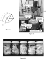
- the shaped water adsorbent composite body could comprise pellets (for example, disk-shaped pellets), pills, spheres, granules, extrudates (for example rod extrudates), honeycombs, meshes or hollow bodies.
- the shaped water adsorbent composite body is formed as a three dimensional body, preferably three dimensionally shaped.
- the shaped water adsorbent composite body comprises an elongate body having a circular or regular polygonal cross-sectional shape.
- the shaped water adsorbent composite body may have a square or triangular cross-sectional shape.
- the shaped water adsorbent composite body comprises an elongate body having a triangular cross-sectional shape, preferably equilateral triangle cross-sectional shape.
- the shaped water adsorbent composite body has equilateral triangle cross-section, preferably the sides of the equilateral triangle are at least 1 mm in length, preferably between 1.0 and 1.5 mm in length.
- the elongate shaped water adsorbent composite body is preferably from 1 to 5 mm in length (longitudinal length), more preferably 1 to 4 mm in length.
- MOFs Metal-organic frameworks
- MOFs comprise the major adsorbent constituent of the shaped water adsorbent composite body.
- MOFs are a crystalline nanoadsorbent with exceptional porosity.
- MOFs consist of metal atoms or clusters linked periodically by organic molecules to establish an array where each atom forms part of an internal surface.
- MOFs as a physisorbent achieve strong adsorption characteristics through the internal surfaces of the MOF porous structure. The strength of this interaction depends on the makeup of the adsorbent surface of the MOF to capture H 2 O molecules.
- the surface chemistry and structure of MOFs can be tuned for a specific application, where performance criteria such as adsorption/desorption rate, capacity as a function of pressure, and operating temperature may be of particular importance.
- the shaped water adsorbent composite body utilises the selectivity of the MOF to adsorb water rather than other components in the air, such as oxygen and nitrogen. That is, capturing of water from a water containing gas (such as air) using a MOF adsorbent.
- the shaped water adsorbent composite body comprises at least 50 wt% water adsorbent MOF, preferably at least 70 wt% water adsorbent MOF, more preferably at least 80 wt% water adsorbent MOF, yet more preferably at least 85 wt% water adsorbent MOF and yet more preferably at least 90 wt% water adsorbent MOF.
- water adsorbent metal organic framework means a water stable metal organic framework that has a good affinity for water, adsorbing water even at low humidity values.
- the heat of adsorption for water ranges from 10 to 100 kJ/mol MOF for water adsorbed on the MOF.
- a water adsorbent MOF should have a good enough affinity for water to enable the MOF to adsorb the water, but not have too high affinity for water that excessive energy needs to be expended to desorb water therefrom.
- the thermodynamics of water adsorption and desorption need consideration to ensure the MOF does not require excessive energy (kJ/mol MOF) to desorb water therefrom, and thereby adversely affect the energy efficiency of the system.
- the water adsorbent metal organic framework comprises at least one of aluminium fumarate (AlFu), MOF-801, MOF-841, M 2 Cl 2 BTDD including Co 2 Cl 2 BTDD, Cr-soc-MOF-1, MIL-101(Cr), CAU-10, alkali metal (Li + , Na + ) doped MIL-101(Cr), MOF-303 (Al), MOF-573, MOF-802, MOF-805, MOF-806, MOF-808, MOF-812, or mixtures thereof.
- the water adsorbent metal organic frameworks are preferably selected from aluminium fumarate, MOF-303, MOF-801, MOF-841, M 2 Cl 2 BTDD, Cr-soc-MOF-1, or MIL-101(Cr).
- the water adsorbent metal organic framework includes a plurality of multidentate ligands of which at least one ligand is from selected from fumarate (fumaric acid) or 3,5-pyrazoledicarboxylic acid (H3PDC) based ligands.
- the metal ion is selected from Fe 3+ , Li + , Na + , Ca 2+ , Zn 2+ , Zr 4+ , Al 3+ , K + , Mg 2+ , Ti 4+ , Cu 2+ , Mn 2+ to Mn 7+ , Ag + , or a combination thereof.
- the metal ion is selected from Zr 4 , Al 3+ or combinations thereof.
- Examples include MOF-303, [Al(OH)(C 5 H 2 O 4 N 2 )(H 2 O)] and MOF-573 [Al(OH)(C 5 H 2 O 4 N 2 )(H 2 O)] constructed by linking aluminium (III) ions and 3,5-pyrazoledicarboxylic acid and AlFu.
- the water adsorbent metal organic framework comprises a porous aluminium-based metal-organic framework (MOF) comprising inorganic aluminium chains linked via carboxylate groups of 1H-pyrazole-3,5-dicarboxylate (HPDC) linkers, and of formula: [Al(OH)(C 5 H 2 O 4 N 2 )(H 2 O)], wherein: each Al (III) ion is capped by four O atoms from four different carboxylate groups and two O atoms from two hydroxyl groups forming AlO 6 octahedra, and the AlO 6 octahedra form corner-sharing chains, depending on the cis- and trans-position of the two adjacent bridging hydroxyl groups, helical chains in MOF-303 (cis-) and MOF-573 (trans-) form respectively.
- MOF porous aluminium-based metal-organic framework
- HPDC 1H-pyrazole-3,5-dicarboxylate
- the MOF is MOF-303, wherein: the linkers further bridge two of the chains together, leading to the formation of a 3D framework delimiting square-shaped one dimensional channels with diameter of 6 ⁇ in diameter (measured by the largest fitting sphere); the MOF-303 has a topology of xhh; and/or the MOF has permanent porosity and a Brunauer-Emmett-Teller (BET) surface area of 1380 and pore volume of 0.55 cm 3 g -1 .
- BET Brunauer-Emmett-Teller
- the MOF is MOF-573, wherein: the linkers further bridge two of the chains together, leading to the formation of a 3D framework delimiting square-shaped one dimensional channels with diameter of 5 ⁇ in diameter (measured by the largest fitting sphere); the MOF has a topology of upt; and/or the MOF has permanent porosity and a Brunauer-Emmett-Teller (BET) surface area of 980 m 2 g -1 and pore volume of 0.56 cm 3 g -1 .
- BET Brunauer-Emmett-Teller
- the water adsorbent MOF comprises aluminium fumarate (AlFu) MOF. Applicant notes that the advantage of using AlFu is that it is the MOF is cheap and easy to make.
- the water adsorbent metal organic framework should preferably embody a number of properties to maximise the functionality of the shaped water adsorbent composite body.
- the water adsorbent metal organic framework preferably has an average surface area of at least 700 m 2 /g, and preferably greater than 800 m 2 /g.
- the water adsorbent metal organic framework also preferably has a pore size of at least 2 nm, preferably greater than 5 nm. The pore size should be sufficient to at least fit a water molecule therein.
- the water adsorbent MOF is provided as a pulverulent material preferably a powder or particulates.
- the water adsorbent metal organic framework has a particle size of less than 800 ⁇ m, preferably less than 600 ⁇ m, and more preferably less than 500 ⁇ m.
- the water adsorbent MOF powder has a particle size of less than 500 ⁇ m, preferably less than 300 ⁇ m, more preferably less than 212 ⁇ m, yet more preferably less than 150 ⁇ m, and in some embodiments less than 88 ⁇ m. It should be appreciated that particle size is typically measured in terms of mesh size through which the particles are sieved.
- the water adsorbent MOF powder has a particle size of less than 60 mesh (250 ⁇ m), preferably less than 100 mesh (149 ⁇ m), preferably less than 140 mesh (105 ⁇ m), and more preferably less than 170 mesh (88 ⁇ m).
- the water adsorbent MOF powder preferably also has a mean particle size of between 10 and 100 ⁇ m, more preferably between 20 and 80 ⁇ m. In other embodiments, the water adsorbent MOF powder has a mean particle size of between 10 and 80 ⁇ m, and preferably between 20 and 60 ⁇ m.
- a water adsorbent MOF powder mixture is not ideal if used in a packed bed adsorption system. Powder alone packs too densely and therefore has too great of pressure drop across the adsorption unit. Therefore powder alone cannot be used.
- the inventors have found that the water adsorbent MOF should be shaped prior to packing into a packed bed water adsorbent system to form a shaped water adsorbent composite body, for example a pellet, for use in a packed bed adsorption system.
- the shaping process is facilitated through the use of a binder. Whilst it may be possible to form a shaped composite body without the use of a binder, shaped composite bodies that include binders in their composition tend to have greater structural strength and stability when used in a packed bed water adsorbent system. A shaped composite body such as a pellet therefore facilitates continuous operation of a packed bed adsorption system.
- hydrophilic binder must be used to impart optimal water adsorption properties to the shaped water adsorbent composite bodies.
- non-hydrophilic binders in particular hydrophobic binders (for example cellulose siloxane)
- hydrophobic binders for example cellulose siloxane
- hydrophilic binders may be used in the shaped water adsorption body.
- the hydrophilic binder can be organic or inorganic, and should not block the pores of the water adsorbent MOF.
- the hydrophilic binder comprises a hydrophilic cellulose derivative, preferably alkyl cellulose, hydroxyalkyl cellulose, or carboxyalkyl cellulose derivatives.
- Particularly suitable hydrophilic binders can be selected from at least one of hydroxypropyl cellulose (HPC), hydroxypropyl cellulose, hydroxyethyl methyl cellulose, hydroxypropyl methyl cellulose (HPMC), ethyl hydroxyethyl cellulose, methyl cellulose, or carboxymethyl cellulose (CMC).
- the hydrophilic binder comprises hydroxypropyl cellulose (HPC).
- HPC hydroxypropyl cellulose
- the additives depend on the application in which the shaped bodies are being used.
- the binder(s) preferably comprise an approved excipient for human consumption. Examples of approved excipients for human consumption include approved excipients for food or pharmaceuticals. Approved food grade or pharmaceutical grade binders are preferred.
- the shaped water adsorbent composite body includes at least 0.1 wt % hydrophilic binder, and preferably at least 0.2 wt% hydrophilic binder. In embodiments, the shaped water adsorbent composite body includes between 0.2 and 5 wt% hydrophilic binder. In some embodiments, the shaped water adsorbent composite body can comprise between 0.5 and 3 wt% hydrophilic binder, more preferably between 0.8 and 2 wt% hydrophilic binder, and yet more preferably about 1 wt% hydrophilic binder. It should be appreciated that the amount of binder is selected based on the properties and particle size (mean size and particle distribution) of the water adsorbent MOF.
- the shaped water adsorbent composite body preferably comprises less than 0.5 wt% lubricant, preferably less than 0.1 wt% lubricant.
- Suitable lubricants include surfactants and their salts. Examples of suitable lubricants include magnesium stearate, aluminium oxide, sodium oleate, glycerides, di-glycerides, tri-glycerides, fatty acids, oils including silicon oils and mineral oils and mixtures thereof. It should be appreciated that the additives depend on the application in which the shaped bodies are being used. Where water is being captured and produced for human consumption the lubricants preferably comprise an approved excipient for human consumption. Examples of approved excipients for human consumption include approved excipients for food or pharmaceuticals. Approved food grade or pharmaceutical grade lubricants are preferred. As discussed below, one or more lubricant is added to the mixture to assist with shaping and forming processes when making the shaped water adsorbent composite body.
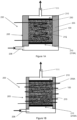
- the apparatus comprises a packed bed adsorption system that includes shaped composite MOF bodies as discussed above.
- the water adsorbent is a metal organic framework composite comprising: at least 50 wt% water adsorbent metal organic framework; and at least 0.1 wt % hydrophilic binder and has at least one mean dimension of greater than 0.5 mm.
- the shaped bodies are collected in a packed bed that is enclosed in the housing.
- the housing is preferably a fluid tight housing.
- the housing preferably includes two spaced apart support membranes configured to allow gas flow therethrough each membrane.
- the plurality of said shaped water adsorbent composite bodies form a packed bed therebetween and being compressed therebetween.
- the shaped water adsorbent composite bodies are packed at a density from 0.10 to 1.0 kg/L, preferably 0.25 to 0.5 kg/L, and more preferably between 0.25 and 0.35 kg/L.
- the shaped water adsorbent composite bodies are packed at a density of about 0.25 kg/L.
- the shaped water adsorbent composite bodies are packed at a density of about 0.29 kg/L.
- the adsorbent is packed tightly and substantially uniformly throughout the packed bed volume to avoid short circuiting of any adsorbent in that packed bed. Any flow that is able to avoid or follow a shorter/ short circuit route through the packed bed will avoid having water removed from that stream. Short circuit flow would adversely affect the energy efficiency and water production rate of the system. Tight and uniform packing also ensures uniform path lengths to optimise adsorption performance.
- the apparatus may use a low or reduced pressure (sometimes referred to as a vacuum environment) to direct the released water to the condenser.
- a low or reduced pressure sometimes referred to as a vacuum environment
- the pressure is less than 100 mbar, preferably less than 50 mbar, more preferably less than 35 mbar. In other embodiments, the pressure is less than 500 mbar.
- the released water is entrained in a gas flow, for example a flow of the water containing gas or another gas such as an inert or other dry gas, and directed to the condenser.
- the flow rate of the water containing gas can also be varied to optimise the water adsorption of the packed bed of shaped water adsorbent composite bodies.
- the water containing gas is fed through the packed bed of shaped water adsorbent composite bodies at as fast a flow rate that is possible for the apparatus whilst the water adsorbent MOF is still adsorbing water from the water containing gas.
- the particular flow rate is dependent on the water content of the water containing gas, as this determines the mass of water a particular volume of gas will contain.
- the water content of the water containing gas is dependent on the relative humidity of that containing gas as well as the temperature and pressure. Where the apparatus is fed ambient air, a higher flowrate will be required for lower humidity air as compared to higher humidity air at the same temperature to maintain a desired cycle time.
- the source of humid air used can be a very low relative humidity, mimicking the humidity levels found on the driest places on Earth.
- the humidity of the air is greater than 20 % at 20 °C, preferably from 20 to 100% at 20 °C, preferably from 20 to 80% at 20 °C, and more preferably from 25 to 60% at 22 °C.
- the humidity of the air is between 40 to 100% at 22 °C, preferably between 40 to 100% at 22 °C, preferably between 40 to 80% at 22 °C, preferably between 40 to 60% at 22 °C, and more preferably about 50% at 22 °C.
- the humidity of the air is between 20 to 100% at 35 °C, preferably between 20 to 80% at 35 °C, preferably between 20 to 60% at 35 °C, and more preferably about 30% at 22 °C.
- the packed bed adsorption system of the present invention is configured for magnetic induction swing water harvesting (adsorption-desorption cycling).
- the water adsorbent is a Magnetic Framework Composite comprising a mixture of at least 50 wt% water adsorbent metal organic framework and from 0.2 to 10 wt% magnetic particles having a mean particle diameter of less than 200 nm
- the water desorption arrangement comprises an alternating current (AC) magnetic field generator located within and/or around the water adsorbent configured to apply an AC magnetic field to the water adsorbent.
- the water adsorbent preferably comprises shaped water adsorbent composite bodies located in a packed bed in the housing.
- the shaped water adsorbent composite bodies are preferably packed at a density from 0.10 to 1.0 kg/L, preferably 0.25 to 0.5 kg/L, and more preferably between 0.25 and 0.35 kg/L.
- the AC magnetic field generator preferably comprises at least one induction coil located within and/or around the packed bed of shaped water adsorbent composite bodies.
- the alternating current magnetic field generator is designed to irradiate the packed bed of shaped water adsorbent composite bodies with an AC magnetic field to release adsorbed water from the packed bed of shaped water adsorbent composite bodies when activated.
- the shaped water adsorbent composite body may include magnetic particles.
- the shaped water adsorbent composite body contains from 0.2 to 10 wt% magnetic particles having a mean particle diameter of less than 200 nm.
- the shaped water adsorbent composite body may comprises between 0.5 and 7 wt% magnetic particles, and in some embodiments between 1 to 5 wt% magnetic particles.
- the use of this composite material combines the exceptional adsorption performance of MOFs and enables the use of high efficiency of magnetic induction heating to desorb water from the MOF.
- the shaped water adsorbent composite body is formed of a magnetic framework composite (MFCs), a composite material which combines magnetic particles with MOF crystals.
- MFCs magnetic framework composite
- the incorporation of magnetic particles (typically micro- or nano- sized magnetic particles) with MOFs allows the generation of heat on exposure to an alternating current (AC) magnetic field.
- AC alternating current
- This process uses the heat generated as a result of static hysteresis and dynamic core losses of ferro/ferrimagnetic particles induced by an external AC magnetic field.
- the generation of heat via induction heating occurs remotely, and resultant heat is targeted, making the heating process isolated and thus energy efficient.
- the magnetic properties of the magnetic framework composites are provided by the magnetic particles mixed within the composite.
- the magnetic particles can be utilised to generate heat on exposure to an alternating current (AC) magnetic field, and thereby can be used to conduct magnetic induction swing adsorption process for water adsorbed on the water adsorbent MOF.
- AC alternating current
- the amount of magnetic particles is selected to provide a desired heat generation profile and magnitude on the application an AC magnetic field.
- the amount of magnetic particles in the shaped water adsorbent composite body is between 0.2 and 10 wt %.
- the shaped water adsorbent composite body may comprise between 0.5 and 7 wt% magnetic particles, and preferably between 1 to 5 wt% magnetic particles.
- the magnetic particles comprise ferromagnetic, paramagnetic, or superparamagnetic particles.
- the magnetic particles comprise metal chalcogenides. Suitable metal chalcogenides comprise magnetic particles comprising any combination of element or ionic form thereof of M selected from at least one of Li, Na, K, Rb, Be, Mg, Ca, Sr, Ba, Sc, Y, Ti, Zr, Hf, V, Nb, Ta, Cr, Mo, W, Mn, Re, Fe, Ru, Os, Co, Rh, Ir, Ni, Pd, Pt, Cu, Ag, Au, Zn, Cd, Hg, B, Al, Ga, In, Tl, Si, Ge, Sn, Pb, As, Sb, Bi, or their combinations, in combination with elements or elemental form of at least one of O, S, Se, or Te.
- the metal chalcogenide have the formula M x N y C z , where M and N are selected from at least one of Li, Na, K, Rb, Be, Mg, Ca, Sr, Ba, Sc, Y, Ti, Zr, Hf, V, Nb, Ta, Cr, Mo, W, Mn, Re, Fe, Ru, Os, Co, Rh, Ir, Ni, Pd, Pt, Cu, Ag, Au, Zn, Cd, Hg, B, Al, Ga, In, Tl, Si, Ge, Sn, Pb, As, Sb, Bi, C is selected from at least one of O, S, Se, Te, x is any number from 0 to 10, y is any number from 0 to 10 and z is any number from 0 to 10.
- the metal chalcogenide particles may in some embodiments have a core-shell structure in which the core comprises at least one metal chalcogenide as previously described and the shell comprises at least one metal chalcogenide as previously described.
- the core-shell structure may include multiple shells.
- the magnetic particles comprise at least one of MgFe 2 O 4 , Fe 3 O 4 , CoFe 2 O 4 , NiFe 2 O 4 , Pyridine-2,6-diamine-functionalized SiO 2 , Pyridine-2,6-diamine-functionalized Fe 3 O 4 , or C-coated Co.
- the magnetic particles can comprise any number of shapes and configurations.
- the magnetic particles comprise particles having irregular shapes.
- the magnetic particles comprise particles having regular three-dimensional shapes, for example spherical, platelet, rod, cylindrical, ovoidal or the like.
- the magnetic particles comprise a plurality of magnetic nanospheres.
- the size of the magnetic particles is typically selected for the desired packed bed application and configuration.
- the magnetic particles comprise nano- or microparticles.
- the magnetic particles have a mean particle diameter of less than 200 nm, preferably less than 150 nm, more preferably between 1 to 100 nm. In some embodiments the magnetic particles have a mean particle diameter of less than 50 nm.
- the magnetic particles have a mean particle diameter of between 1 and 200 nm, preferably between 5 and 100 nm, more preferably between 5 to 30 nm, and yet more preferably between 5 to 30 nm. In some embodiments, the magnetic particles have a mean particle diameter of around 20 nm. It is noted that the magnetic particles need to be large enough to not foul the pores of the water adsorbent MOF.
- the combination of the magnetic particles with MOFs to form a magnetic framework composite material yields an adsorbent with exceptional adsorption behaviour as a result of the MOFs and high efficiency of induction heating as a result of the magnetic particles.
- a second aspect of the present invention provides a method of capturing a water content from a water containing gas as defined in the claims, the method comprising at least one cycle of:
- the second aspect of the present invention also provides a method of capturing a water content from a water containing gas using the apparatus according to the first aspect of the present invention.
- the method comprises at least one cycle of:
- a moisturized gas stream is fed over the water adsorbent.
- the water desorption arrangement is activated to heat. Consequently, the water adsorbent is driven to release at least part of the adsorbed water content.
- the desorbed water can be condensed in a condenser system, for example in a cold trap.
- the method preferably further comprises the step of: closing the inlet and outlet of the housing prior to operating the at least one water desorption arrangement. This creates a closed gas sealed environment in the housing allowing capture of the water content therein.
- the relative humidity inside the housing increases to high values, and water condenses in the condenser system for collection.
- this method is a cyclical method, where the steps of adsorbing water in the water adsorbent, releasing that adsorbed water through operation of the water desorption arrangement and condensing that water is conducted in a repetitive cycle so to continuously produce water.
- the cycle time typically depends on configuration of the water adsorbent and the adsorption system, the amount of water adsorbent MOF, breakthrough point, saturation point, temperature, pressure and other process conditions.
- one cycle of the method has a duration of less than 10 hours, preferably less than 8 hours, more preferably less than 7 hours, and more preferably 6 hours or less.
- the cycle time of this method steps are approximately 30 minutes in duration. However, other cycle times between 10 minutes to 10 hours could be possible depending on the configuration of the apparatus.
- the apparatus of the present invention can be configured for temperature swing water harvesting (adsorption - desorption cycling).
- a heat source is required to heat the packed bed of shaped water adsorbent composite bodies.
- the apparatus of the present invention is configured for magnetic induction swing water harvesting.
- the step of operating the at least one water desorption arrangement comprises applying an alternating current magnetic field to a packed bed of shaped water adsorbent composite bodies, thereby generating heat within the shaped water adsorbent composite bodies, so to release at least a portion of the adsorbed water therefrom into a product fluid flow
- the shaped water adsorbent composite comprises at least 50 wt% water adsorbent metal organic framework; and at least 0.1 wt % hydrophilic binder and from 0.2 to 10 wt% magnetic particles having a mean particle diameter of less than 200 nm.
- the shaped water adsorbent composite bodies in this method undergo magnetic induction vacuum swing adsorption to capture water from the water containing gas fed into the packed bed of shaped water adsorbent composite bodies.
- Application of the AC magnetic field depends on the amount of moisture adsorbed in the shaped water adsorbent composite bodies in the packed bed.
- This method therefore takes advantage of the high energy conversion efficiency of magnetic induction heating.
- the apparatus and method has an energy conversion efficiency of greater than 90%, preferably greater than 95% and in some embodiments up to 98% was achieved.
- the use of rapid heating through magnetic induction heating enables short cycle times to be achieved.
- the method has a cycle time of less than 2 hours, preferably less than 1 hour.
- Adsorption is a transient process. The amount of material adsorbed within a bed depends both on position and time. The active adsorption region of a packed bed shifts away from the inlet and through the bed as time goes on. This mass transfer zone moves through the bed until it "breaks through”. The fluid emerging from the bed will have little or no solute remaining - at least until the bulk of the bed becomes saturated. The breakthrough point occurs when the concentration of the fluid leaving the bed spikes as unadsorbed solute begins to emerge. The bed still adsorbs water, though at a slower rate than before the breakthrough point until the bed becomes saturated, and no further water can be adsorbed, defined as the "saturation point" of the bed.
- the alternating current magnetic field is preferably applied when the packed bed has adsorbed water equivalent to at least 75% of the saturation point, preferably at least 80%, more preferably at least 90% of the saturation point of the packed bed. This ensures that the adsorption capacity of the packed bed is substantially utilised, but allows the water to be released before the packed bed is fully saturated.
- the AC magnetic field is applied for a length of time required to substantially release the water adsorbed on the shaped water adsorbent composite bodies in of the packed bed. That application time depends on the shape, size and configuration of the packed bed, shape, size and configuration of the AC magnetic field generator, the applied magnetic field strength and the amount of magnetic particles in the shaped water adsorbent composite bodies.
- the AC magnetic field is applied for at least 1 second. In embodiments, the AC magnetic field is applied for between 1 and 120 seconds, preferably between 1 and 60 seconds, more preferably from 10 to 30 seconds.
- the magnetic field strength applied to the packed bed of shaped water adsorbent composite bodies is typically tailored to the shape, size and configuration of that packed bed.
- the magnetic field strength is at least 10 mT, preferably at least 12 mT, preferably about 12.6 mT.
- the selected magnetic field strength depends on the particular application, and is generally selected to provide the lowest power consumption and thus lowest magnetic field strength for the maximum heat to desorb water from the water adsorbent MOF.
- the frequency of the AC magnetic field can be selected to provide maximum heating.
- the frequency of the AC magnetic field is between 200 and 300 kHz, preferably between 250 and 280 kHz, and more preferably from 260 to 270 kHz. Again, the frequency can be selected for a particular application and be tailored/ optimised to provide the greatest heating for the lowest power consumption.
- the water containing gas can comprise any number of gases, such as nitrogen, oxygen or the like.
- the water containing gas comprises air, preferably atmospheric air, more preferably ambient air. The method can therefore by used to separate and capture water content from atmospheric air and thereby capture water.
- the condenser system is used separate the water content of the product fluid flow (typically gas with entrained water vapour) to produce water. It is to be understood that a large variety of condenser arrangements are possible, and are selected to meet the particular requirements of a designed system.
- the condenser is used to convert water vapour in the product fluid flow into liquid water.
- the condenser comprises a heat transfer/ cooling device such as a cooling trap, air coils, surface condensers or another heat exchange device.
- the metal organic framework adsorbent can be activated before use (i.e. use for moisture adsorption) by triggering them by heating the composite bodies and passing (feeding) a dry nitrogen stream through the column.
- the water adsorbent comprises composite bodies that include magnetic particles
- heating can be achieved with an alternating current magnetic field. Activation of the material was performed until the humidity of the out coming gas stream was zero.
- the method and associated apparatus has a water production capacity of at least 2.8 L/kg of MOF, more preferably at least 3.5 L/kg of MOF, yet more preferably at least 4 L/kg of MOF, and in some embodiments about 4.1 L/kg of MOF at 20 % RH and 35 °C.
- the typical energy use is between 10 and 15 kWh/L, typically around 12 kWh/L water produced.
- a third aspect of the present invention provides an apparatus for capturing a water content from a water containing gas, the apparatus comprising:
- This third aspect of the present invention provides a water capturing apparatus that includes shaped bodies that uses magnetic swing induction heating to desorb water adsorbed within and on the shaped bodies.
- the shaped bodies are collected in a packed bed that is enclosed in the housing.
- the housing is preferably a fluid tight housing.
- the apparatus also includes an alternating current magnetic field generator designed to irradiate the packed bed of shaped water adsorbent composite bodies with an AC magnetic field to release adsorbed water from the packed bed of shaped water adsorbent composite bodies when activated.
- the apparatus is configured to enable the shaped water adsorbent composite bodies to undergo magnetic induction swing adsorption to capture water from a water containing gas fed into the packed bed of shaped water adsorbent composite bodies.
- the AC magnetic field generator comprises at least one induction coil located within and/or around the packed bed of shaped water adsorbent composite bodies.
- one or more induction coils are embedded within and surrounded by the shaped water adsorbent composite bodies in the packed bed so to use the whole magnetic field generated by the induction coil or coils.
- the induction coil or coils are configured to sit within a central section of the packed bed, occupying from 50% to 90%, preferably from 70 to 80 % of the axial height (depth) of the packed bed.
- the housing has a fluid inlet and a fluid outlet through which a fluid, preferably the moisture containing gas and product fluid is configured to flow.
- the housing can have any suitable configuration.
- the housing comprises a container or canister, for example a substantially cylindrical container or canister.
- the housing is preferably fluid tight, with only fluid access and egress through the inlet and outlet of that housing.
- the housing comprises a flat, high surface area container. It should be appreciated that a variety of container and canister shapes and configurations could be used.
- the housing may be exchangeable or is installed fixed in the system.
- the plurality of said shaped water adsorbent composite bodies is preferably arranged in the housing in a packed bed system.
- the housing can include two spaced apart support membranes configured to allow gas flow therethrough each membrane, the plurality of said shaped water adsorbent composite bodies forming a packed bed therebetween and preferably being compressed therebetween.
- the apparatus of this fifth aspect can further include a condenser system for cooling a fluid flow from the packed bed of shaped water adsorbent composite bodies.
- the condenser comprises a cooling device, for example a cooling trap.
- potable water can be expeditiously produced using the apparatus of this aspect of the present invention.
- This apparatus utilises a packed bed of the shaped water adsorbent composite bodies of the first aspect of the present invention in a magnetic induction vacuum swing adsorption system to separate and thus capture water from an water bearing gas (such as humid air) and release and harvest that captured content using a condenser.
- an water bearing gas such as humid air
- a fourth aspect of the present invention provides a method of capturing a water content from a water containing gas using the apparatus according to the fifth aspect of the present invention, comprising at least one cycle of (the steps of):
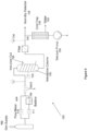
- a moisturized gas stream is fed through a packed adsorption column.
- an alternating current magnetic field is applied. Consequently, the pellets start heating up rapidly forcing the water to be released.
- the desorbed water is condensed in a condenser, for example in a cold trap.
- This method therefore takes advantage of the high energy conversion efficiency of magnetic induction heating.
- the apparatus and method has an energy conversion efficiency of greater than 90%, preferably greater than 95% and in some embodiments up to 98% was achieved. Furthermore, the use of rapid heating through magnetic induction heating enables short cycle times to be achieved.
- this method is a cyclical method, where the steps of adsorbing water in the shaped water adsorbent composite bodies, releasing that adsorbed water through application of the AC magnetic field and condensing that water is conducted in a repetitive cycle so to continuously produce water.
- the cycle time typically depends on the configuration of the packed bed and the adsorption system, the amount of shaped water adsorbent composite bodies, the depth of the packed bed, breakthrough point, saturation point and characteristics of the particular pack bed, temperature, pressure and other process conditions.
- the cycle time of this method steps are approximately 30 minutes in duration. However, other cycle times between 10 minutes to 2 hours could be possible depending on the configuration of the apparatus and packed bed and process conditions.
- the present invention can also provide a method of forming a shaped water adsorbent composite body for the adsorption system of the first aspect.
- the method comprises the steps of:
- This aspect of the present invention provides a method of forming the shaped water adsorbent composite body used in various embodiments of the present invention.
- the composite powder mixture (typically a pulverulent material) comprising a powder mix of metal organic framework and a hydrophilic binder, is formed into a paste using a solvent, which can then be shaped, for example by extrusion or palletising processes into the desired shaped body.
- the solvent used to form the shaped body can be any suitable solvent that has good interaction with the constituents of the composite powder mixture.
- Suitable solvents are preferably selected from a non-basic polar solvent and/or a non-self ionising polar solvent.
- the solvent preferably comprises an alcohol, such as methanol, ethanol, C2-C9 alcohols including their branched isomers, or water, more preferably deionised water.
- the hydrophilic binder and a liquid solvent are added to the composite powder mixture to assist in the formation of a suitable paste for shaping processes.
- the composite paste comprises a thick, soft, moist mixture.
- the paste preferably has sufficient viscosity to retain a form when shaped into a desired configuration in the forming/ shaping step.
- the amount of solvent and composite powder material is typically mixed to provide a suitable paste consistency for shaping processes such as extrusion or pelletising.
- the shaped body preferably comprises the water adsorbent MOF and the hydrophilic binder.
- the solvent is purely used to form the paste which is evaporated or otherwise removed from the shaped composite material during the heat treatment step.
- Magnetic particles are included in the formed shaped composite material.
- the composite powder mixture further comprises from 0.2 to 10 wt% magnetic particles having a mean particle diameter of less than 200 nm.
- the composite paste can be formed into the shaped body using a variety of processes.
- forming the composite paste into a shaped body comprises at least one of extruding, pelletising or moulding the composite paste into a desired three-dimensional configuration.
- Preferred methods include rod extrusion or tableting.
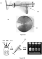
- the shaped body is formed by an extrusion or similar process such that the composite paste is extruded into an elongate body, that elongate body is preferably subsequently longitudinally divided, typically to a length suitable used in a packed bed of a packed bed adsorption system. It is preferred that after extrusion the extruded elongated body is allowed to dry, for example air dry, for a period of time prior to being longitudinally divided. That drying time can vary, but is typically at least 10 minutes. Afterwards, the extruded body is cut into 3 to 5 mm long shaped bodies, preferably pellets.
- the shaping step can be performed in the presence of lubricants and/or other additional substances that stabilize the materials to be agglomerated.
- Suitable lubricants include surfactants and their salts.
- suitable lubricants include magnesium stearate, aluminium oxide, sodium oleate, glycerides, di-glycerides, tri-glycerides, fatty acids, oils including silicon oils and mineral oils and mixtures thereof. It should be appreciated that the additives depend on the application in which the shaped bodies are being used.
- the lubricants preferably comprise an approved excipient for human consumption where water is being produced for human consumption. Examples of approved excipients for human consumption include approved excipients for food or pharmaceuticals. Approved food grade or pharmaceutical grade lubricants are preferred.
- lubricants are added to the mixture to assist with shaping and forming processes when making the shaped body.
- the lubricant can be mixed in the powder mixture with the binder to form part of the powder mixture.
- the lubricant is applied to the surface of the shaping device, for example an extruder or pelletiser, to lubricate the outer surface only.
- the resulting shaped water adsorbent composite body preferably comprises less than 0.5 wt% lubricant, preferably less than 0.1 wt% lubricant.
- the shaped body/ bodies are preferably formed with dimensions that are suitable for use in a packed bed adsorption system, in which a plurality of the shaped bodies are packed at a high packing density 0.10 to 0.5 kg/L, preferably 0.25 to 0.4 kg/L between two support surfaces.
- the dimensions of the shaped body can be optimised to suit this application.
- the shaped water adsorbent composite body has at least one mean dimension of greater than 0.5 mm when used in a packed bed adsorption system. This ensures the adsorbent composite body has sufficient size to allow gas flow around. For example, fine powder (for example having an average particle size of less than 10 micron) provides too dense packing for use in a packed bed of a packed bed adsorption system.
- the shaped body has at least one mean dimension of greater than 0.8 mm, preferably at least 1 mm, preferably at least 1.2 mm, and yet more preferably at least 1.5 mm.
- each of the mean width, mean depth and mean height of the shaped body are greater than 0.5 mm, and preferably greater than 1 mm.
- the shaped body can be formed to have any suitable geometry.
- the shape of the shaped water adsorbent composite body has an impact on the pressure drop of local fluid flow (in the vicinity of the bodies), and therefore, the performance of any packed bed adsorption system.
- the shaped body could comprise pellets, for example, disk-shaped pellets, pills, spheres, granules, extrudates, for example rod extrudates, honeycombs, meshes or hollow bodies.
- the shaped body is three dimensional, preferably three dimensionally shaped.
- the shaped body comprises an elongate body having a circular or regular polygonal cross-sectional shape.
- the shaped body comprises a triangular cross-sectional shape, and more preferably an equilateral triangle cross-sectional shape.
- the shaped body may have a square or triangular cross-sectional shape.
- the shaped body has equilateral triangle cross-section, preferably the sides of the equilateral triangle are at least 1 mm in length, preferably between 1.0 and 1.5 mm in length.
- the elongate shaped body is preferably from 1 to 5 mm in length (longitudinal length), more preferably 1 to 4 mm in length. In some embodiments, the elongate shaped body is 3 to 5 mm in length.
- the heating step is preferably conducted for sufficient time to remove the solvent from the shaped body.
- the heating step is preferably conducted at a temperature of between 80 to 150 °C, preferably between 90 and 120 °C.
- the heating step can be conducted for at least 1 hour, preferably at least 2 hours, more preferably at least 5 hours, yet more preferably at least 8 hours, and yet more preferably at least 10 hours.
- the pressure is selected to assist solvent removal. In embodiments, the pressure is less than 100 mbar, preferably less than 50 mbar, more preferably less than 35 mbar. In other embodiments, the pressure is less than 500 mbar.
- the heating step is conducted in an insert gas atmosphere, for example nitrogen or argon.
- the heating step can include an additional activation step where the shaped adsorption body/ bodies are dried at an elevated temperature to ensure the pores of the water adsorbent MOF are free of moisture or solvent.
- this activation heating step comprises heating the shaped adsorption body to at least 120 °C, preferably between 120 and 150 °C for at least 5 hours, preferably at least 6 hours, more preferably from 6 to 10 hours, and more preferably from 6 to 8 hours.
- the activation heating step is preferably conducted at a reduced pressure of less than 200 mbar, preferably less than 100 mbar, and more preferably less than 50 mbar.
- the shaped adsorption body is heated to a temperature of 130 °C at a pressure of less than 200 mbar, preferably less than 100 mbar, more preferably less than 50 mbar to activate the MOF for 6 to 8 hours.
- the shaped adsorption bodies can be activated by triggering them with an alternating current magnetic field within an inert gas flow, for example dry nitrogen stream. Activation of the shaped adsorption bodies can be performed until the humidity of the out-coming gas stream is zero.
- the material is preferably cooled down to at most 80 °C, preferably at most 60 °C under reduced pressure of at most 500 mbar, preferably at most 100 mbar.
- water produced from the apparatus and method according to embodiments of the present invention can be used for any purpose, including but not limited to;
- the present invention provides an apparatus that provides selective control of the adsorbing and desorbing phases of a MOF based water adsorbents water harvesting cycle.
- the apparatus includes a water desorption arrangement which allows the MOF based water adsorbent to adsorb water when in a deactivated state, and then apply desorption conditions to the water adsorbent to desorb water from the water adsorbent when in an activated state.
- This selective operation of the water desorption arrangement between the deactivated and activated states enables the efficiency of water desorption arrangement to be optimised using more efficient energy desorption arrangements to desorb water from the metal organic framework based water adsorbent compared for example to utilising solar energy, and in some embodiments that can simultaneously condense the water content of any product gas flow.
- the water desorption arrangement can take any number of forms.
- temperature swing adsorption is undertaken to achieve water harvesting. This can be achieved using direct heating methods, or in some cases using magnetic induction swing adsorption.
- the apparatus can be configured as a magnetic swing water adsorption apparatus to harvest a water content from a water containing gas, such as atmospheric air.
- a magnetic swing water adsorption apparatus to harvest a water content from a water containing gas, such as atmospheric air.
- FIGs 1A or 1B One form of this type of apparatus 200 is illustrated in Figures 1A or 1B .
- FIGs 1A and 1B illustrate an apparatus 200 for capturing a water content from a water containing gas that uses a shaped water adsorbent composite body formulated with magnetic particles as discussed above.
- the apparatus 200 comprises a cylindrical housing 205 which includes inlet 208 and outlet 211.
- Housing 205 contains a packed bed 215 of shaped water adsorbent composite bodies 100 (see Figure 2C ), the composition of which is described in more detail below.
- a fluid distributor disc 210 proximate the base and lid/ top of the housing 205 is used to retain the shaped adsorption material 215 between the discs 205.
- Each fluid distributor disc 210 comprises a metal disc with multiple holes drilled therethrough to allow fluid to flow through the packed shaped adsorption material.
- the shaped adsorption material forms a compressed packed bed between the discs 210, and are compressed therebetween so that the adsorbent shaped bodies 100 are tightly packed therein, thereby avoiding any flow short circuiting.
- an alternating current (AC) induction coil 250 is located within and surrounded by the packed bed 215 of shaped water adsorbent composite bodies 100 ( Figure 2C ).
- the induction coil 250 is configured to apply an AC magnetic field to the packed bed 215 of shaped water adsorbent composite bodies.
- the induction coil 250 is embedded within the packed bed 215 to optimise the use of the applied magnetic field when the induction coil 250 is operated.
- the housing 205 includes magnetic dampening material 255 to reduce magnetic field leakage from the container to the surroundings. This can be important in some applications where a magnetic field could deliriously affect the operation of proximate equipment, or irradiate people or objects.
- an alternating current (AC) induction coil 250 is located external of the housing 205, but in a location around the housing which extends around the packed bed 215 of shaped water adsorbent composite bodies 100.
- the induction coil 250 is configured to apply an AC magnetic field to the packed bed 215 of shaped water adsorbent composite bodies.
- this induction coil 250 is not as energy efficient as shown in Figure 1A due to losses through the material of housing.
- a further housing may be used to enclose the induction coil which includes magnetic dampening material 255 to reduce magnetic field leakage to the surroundings.
- a water containing gas is flowed through the packed bed of shaped bodies 215 such that the shaped water adsorbent composite bodies adsorb water from the water containing gas.
- the induction coil 250 is operated to apply an alternating current magnetic field thereby generating heat within the shaped water adsorbent composite bodies, so to release at least a portion of the adsorbed water therefrom into a product fluid flow.
- the shaped water adsorbent composite bodies therefore undergo magnetic induction vacuum swing adsorption to capture water from the water containing gas fed into the packed bed of shaped water adsorbent composite bodies 215.
- a condenser can be used to subsequently separate the water content of the product fluid flow (typically gas with entrained water vapour) to produce a captured water product.
- a low or reduced pressure sometimes referred to as a vacuum environment
- a positive pressure gas flow for example a flow of the water containing gas or another gas such as an inert or other dry gas, to direct the released water to the condenser.
- the above described method is cyclically applied, where the steps of adsorbing water in the shaped water adsorbent composite bodies 100, releasing that adsorbed water through application of the AC magnetic field and condensing that water is conducted in a repetitive cycle so to continuously produce water.
- the apparatus illustrated in Figures 1A to 1E each use a shaped water adsorbent composite body 100 ( Figure 2C ) in a packed bed as the water adsorbent.
- the metal organic framework composite can be provided in an apparatus of the present invention in any form suitable to the particular apparatus configuration.
- the inventors envisage that this may be in any number of composite forms including (but not limited to) shaped bodies (for example pellets or extrusions), coatings, plates, sheets, strips or the like.
- the shaped water adsorbent composite body 100 used in the apparatus discussed in relation to the apparatus shown in Figures 1A to 1E comprises a mixture of water adsorbent metal organic framework (MOF), and a hydrophilic binder which is optimised for use in a packed bed adsorption system. That mixture is composed of at least 50 wt% water adsorbent metal organic framework and at least 0.1 wt % hydrophilic binder.
- MOF water adsorbent metal organic framework
- the shaped water adsorbent composite body 100 is configured to harvest water using a magnetic induction swing adsorption system.
- the shaped water adsorbent composite body additionally contains from 0.2 to 10 wt% magnetic particles having a mean particle diameter of less than 200 nm.
- the use of magnetic particles in the composition forms enables inductive heat generation to be used for water desorption.
- This type of composite known as a magnetic framework composite, combines the exceptional adsorption performance of MOFs and the high efficiency of magnetic induction heating.
- the metal organic framework composite material can be shaped into any suitable configuration for use in a packed adsorption system.
- the metal organic framework composite material is exemplified as a elongate shaped water adsorbent composite body 100 having a triangular cross-section, for example as shown in Figure 2C .
- Figure 2C a triangular cross-section
- other shapes for example spherical, cylindrical, cubic, ovoid or the like could equally be used.
- the shaped water adsorbent composite body 100 comprises an elongate body having an equilateral triangle cross-sectional shape.
- the sides S of the equilateral triangle are at least 1 mm in length, preferably between 1.0 and 1.5 mm in length.
- the shaped water adsorbent composite body is preferably from 1 to 5 mm in length (longitudinal length, L), more preferably 1 to 4 mm in length.
- the elongated triangular shape is selected to increase packing density of the shaped water adsorbent composite bodies 100 within a packed bed (for example packed bed 215 shown in Figures 1A and 1B ). Previous studies have shown that this shape has one of the highest packing densities in packed bed configurations.
- a high packing density is preferred for optimum utilisation and heat generation from an applied heat source.
- a cylindrical pellet shape has a packing density of around 0.19 kg/L.
- An elongated equilateral triangular shaped pellet has a packing density of around 0.29 kg/L.
- the water adsorbent metal organic framework used in the shaped water adsorbent composite body 100 can be selected from a range of suitable water adsorbent MOFs.
- a wide variety of water adsorbent MOFs are known, for example as discussed in Furukawa et al "Water Adsorption in Porous Metal-Organic Frameworks and Related Materials” Journal of the American Chemical Society 136(11), March 2014 and H W B Teo and A Chakraborty 2017 IOP Conf. Ser.: Mater. Sci. Eng. 272 012019 the contents of which should be understood to be incorporated into this specification by these references.
- the water adsorbent metal organic framework comprises at least one of aluminium fumarate, MOF-303 (Al), MOF-573 (Al), MOF-801 (Zr 6 O 4 (OH) 4 (fumarate) 6 ), MOF-841 (Zr 6 O 4 (OH) 4 (MTB) 2 (HCOO) 4 (H 2 O) 4 ), M 2 Cl 2 BTDD (including Co 2 Cl 2 BTDD), Cr-soc-MOF-1, MIL-101(Cr), CAU-10, alkali metal (Li+, Na+) doped MIL-101(Cr), MOF-802 (Zr 6 O 4 (OH) 4 (PZDC) 5 (HCOO) 2 (H 2 O) 2 ), MOF-805 (Zr 6 O 4 (OH) 4 [NDC-(OH) 2 ] 6 ), MOF-806 (Zr 6 O 4 (OH) 4 [NDC-(OH) 2 ] 6 ), MOF-808 (Zr 6 O 4
- Preferred water adsorbent metal organic frameworks are aluminium fumarate, MOF-303 (Al), MOF-801, MOF-841, M 2 Cl 2 BTDD, Cr-soc-MOF-1, and MIL-101(Cr).
- Optimising the selection of a water adsorbing MOF involves a number considerations, including:
- the water adsorbent MOF preferably comprises aluminium fumarate (AlFu) MOF in these embodiments.
- AlFu aluminium fumarate
- AlFu Aluminium fumarate
- AlFu aluminium fumarate
- the structure and water adsorption properties of AlFu are well known, for example as detailed in Teo et al. (2017). Experimental study of isotherms and kinetics for adsorption of water on Aluminium Fumarate. International Journal of Heat and Mass Transfer Volume 114, November 2017, Pages 621-627 , the contents of which are to be understood to be incorporated into this specification by this reference.
- Teo the crystal structure of AlFu resembles MIL-53 as it also consists of infinite Al OH Al chains connected by fumarate linkers.
- aluminium fumarate was selected as a preferred choice of MOF for the inventive water capturing apparatus and system due to:
- the MOF component of the present invention is not restricted to Aluminium fumarate, and that other water adsorbent MOFs can also be used in the composition of the water adsorbent composite body.
- the selection of the appropriate binder is also important to the overall properties of the shaped adsorption body.
- a hydrophilic binder must be used to impart optimal water adsorption properties to the shaped water adsorbent composite bodies.
- non-hydrophilic binders and in particular hydrophobic binders for example cellulose siloxane
- the use of a hydrophilic binder is therefore important for optimal moisture capture properties of the packed bed water adsorption system.
- hydrophilic binders can be selected from at least one of hydrophilic cellulose derivatives such as hydroxypropyl cellulose, hydroxyethyl methyl cellulose, hydroxypropyl methyl cellulose (HPMC), ethyl hydroxyethyl cellulose, methyl cellulose, or carboxymethyl cellulose (CMC) as previously set out in this specification.
- hydrophilic cellulose derivatives such as hydroxypropyl cellulose, hydroxyethyl methyl cellulose, hydroxypropyl methyl cellulose (HPMC), ethyl hydroxyethyl cellulose, methyl cellulose, or carboxymethyl cellulose (CMC) as previously set out in this specification.
- hydrophilic binder is hydroxypropyl cellulose (HPC).
- the shaped water adsorbent composite body can further comprise a lubricant content, preferably less than 0.5 wt% lubricant, and more preferably less than 0.1 wt% lubricant.
- Suitable lubricants include surfactants and their salts. Examples of suitable lubricants include magnesium stearate, aluminium oxide, sodium oleate, glycerides, di-glycerides, tri-glycerides, fatty acids, oils including silicon oils and mineral oils and mixtures thereof.
- the lubricant content can assist with the shaping and forming processes of the shaped water adsorbent composite body.
- the shaped water adsorbent composite bodies can be configured to harvest water using a magnetic induction swing adsorption system.
- the shaped water adsorbent composite body 100 ( Figure 2C ) comprises a mixture composed of at least 50 wt% water adsorbent metal organic framework, at least 0.1 wt % hydrophilic binder and from 0.2 to 10 wt% magnetic particles having a mean particle diameter of less than 200 nm.
- the mixture is optimised for use in a packed bed adsorption system.
- the magnetic particles comprise a ferromagnetic, paramagnetic, or superparamagnetic particles (typically micro or nano-particle).
- the magnetic particles comprise metal chalcogenides.
- Suitable metal chalcogenides comprise magnetic particles comprising any combination of element or ionic form thereof M selected from at least one of Li, Na, K, Rb, Be, Mg, Ca, Sr, Ba, Sc, Y, Ti, Zr, Hf, V, Nb, Ta, Cr, Mo, W, Mn, Re, Fe, Ru, Os, Co, Rh, Ir, Ni, Pd, Pt, Cu, Ag, Au, Zn, Cd, Hg, B, Al, Ga, In, Tl, Si, Ge, Sn, Pb, As, Sb, Bi, or their combinations, in combination with elements or elemental form of at least one of O, S, Se, or Te.
- M Li, Na, K, Rb, Be, Mg, Ca, Sr, Ba, Sc, Y, Ti, Zr, Hf, V, Nb, Ta, Cr, Mo, W, Mn, Re, Fe, Ru, Os, Co, Rh, Ir, Ni, Pd, Pt, Cu, Ag,
- the crystallisation facilitators comprise metal chalcogenide having the formula M x N y C z , where M,N are selected from at least one of Li, Na, K, Rb, Be, Mg, Ca, Sr, Ba, Sc, Y, Ti, Zr, Hf, V, Nb, Ta, Cr, Mo, W, Mn, Re, Fe, Ru, Os, Co, Rh, Ir, Ni, Pd, Pt, Cu, Ag, Au, Zn, Cd, Hg, B, Al, Ga, In, Tl, Si, Ge, Sn, Pb, As, Sb, Bi, C is selected from at least one of O, S, Se, Te, x is any number from 0 to 10, y is any number from 0 to 10 and z is any number from 0 to 10.
- M,N are selected from at least one of Li, Na, K, Rb, Be, Mg, Ca, Sr, Ba, Sc, Y, Ti, Zr, Hf, V, Nb, Ta
- the metal chalcogenide particles may in some embodiments have a core-shell structure in which the core comprises at least one metal chalcogenide as previously described and the shell comprises at least one metal chalcogenide as previously described.
- the core-shell structure may include multiple shells.
- the magnetic particles comprise at least one of MgFe 2 O 4 , Fe 3 O 4 , C-coated Co, CoFe 2 O 4 , NiFe 2 O 4 , Pyridine-2,6-diamine-functionalized SiO 2 , or Pyridine-2,6-diamine-functionalized Fe 3 O 4 .
- the combination of the magnetic particles with MOFs to form a magnetic framework composite material yields an adsorbent with exceptional adsorption behaviour as a result of the MOFs and high efficiency of induction heating as a result of the magnetic particles.
- MFC pellets The synthesis of AlFu and the preparation of shaped water adsorbent composite bodies comprising AlFu magnetic framework composite material (MFC), hereafter referred to as MFC pellets, are described.
- MFC magnetic framework composite material
- the examples demonstrate that the experimental system can produce water repeatedly, with 1.2 grams of water having been produced from roughly 3 cycles of the described method and system. Cycle times were approximately 30 minutes in duration.
- 0.4 g of water was captured using 5 g of the inventive shaped composite material within 28 minutes. This provides the following production and energy use:
- the system described in Yaghi 1 and Yaghi 2 uses sunlight as energy source for regeneration of the MOF.
- This device was reported as being capable of capturing 2.8 litres of water per kilogram of MOF daily at relative humidity levels as low as 20% at 35 °C in Yaghi 1.
- Yaghi 2 indicates that about 0.75 g of water was produced from 3 g of MOF within 16.5 hours in the same conditions. This equates to an anticipated water production capacity of 0.25 L/kg of MOF daily.
- the process of the present invention therefore has a significantly higher water production rate than the system taught in Yaghi.
- Yaghi 1 originally claimed that their device was capable of capturing 2.8 litres of water per kilogram of MOF daily at relative humidity levels as low as 20% at 35 °C.
- this higher production rate appears to have been greatly overestimated in that paper, as further experimental work published in Yaghi 2 using the same set up reports a production rate being an order of magnitude lower at 0.25 litres of water per kilogram of MOF daily at 20% RH and 35 °C.
- the production rate published in Yaghi 2 reflects the actual production rate of this MOF-801 based system.
- aluminium fumarate MOF aluminium fumarate MOF
- preparation of aluminium fumarate MFC pellets are described.
- solution A aluminium sulfate octadecahydrate was dissolved in deionized water using a magnetic stirrer 406.
- Precursor solution B was prepared by dissolving sodium hydroxide pellets and fumaric acid with a purity of 99% in deionized water under stirring with a magnetic stirrer (not shown). The composition of both solutions can be taken from Table 1.
- Table 1 Composition of precursor solutions for aluminium fumarate synthesis Precursor Solution A Precursor Solution B Aluminium Sulfate Deionized Water Sodium Hydroxide Fumaric Acid Deionized Water Batch I 35 g 150 ml 13.35 g 12.9 g 191 ml Batch II 90 g 385.7 ml 34.33 g 33.17 g 491.1 ml
- Solution B was then filled into a round bottom flask 410 and heated up to 60 °C using a heating mantel 408.
- a mechanical stirrer 402 was used to stir the liquid. When 60 °C were reached, precursor solution A was added. The mixture was then stirred for 20 minutes at 60 °C measured using temperature transducer 404.
- the suspension was filled into centrifuge tubes (not shown) and centrifuged for 8 to 10 minutes at 6000 rpm for Batch I and 4500 rpm for Batch II, respectively.
- the liquid was then removed from the sedimented MOF crystals. After that aluminium fumarate was washed using the following procedure.
- deionized water was added to the MOF crystals.
- the suspension was then shaken by hand until the sediments were homogenously mixed up.
- the suspension was mixed for 15 minutes onto a roller mixer for Batch I and an orbital shaker for Batch II, respectively.
- the suspension was centrifuged using the same settings as mentioned before. After removing the liquid, the washing procedure with deionized water was repeated for another three times.
- Aluminium fumarate was washed with methanol for one time following the same procedure as described before. Aluminium fumarate after the washing procedure is shown in Figure 2B .
- the MOF crystals were pre-dried overnight in a glove bag under nitrogen atmosphere. Afterwards, the MOF was dried overnight in an oven at 100 °C under nitrogen atmosphere. Subsequently, the temperature was increased to 130 °C and the oven was evacuated to activate the MOF for 6 to 8 hours.
- MNPs magnetic nanoparticles
- a syringe with a round nozzle was used (not illustrated).
- a hand extruder 500 with a triangular shaped nozzle 505 was chosen.
- the extruder is illustrated in Figure 3A .
- the triangular shaped extrusion attachment 505 was chosen in order to increase the packing density of the produced pellets as explained previously.
- magnesium stearate was used as lubricant for preparation of pellets from Batch II.
- the magnesium stearate powder was greased onto the inner walls of the hand extruder 500.
- the paste was extruded onto filter paper and dried for at least 10 minutes. Afterwards, the extruded MOF was cut into 3 to 5 mm long pellets using a razor blade.
- the pellets were then dried in an oven at 100°C under vacuum (reduced pressure of less than 100 mbar) for 24 hours.
- the different MOF composite pellets (Aluminium fumarate and aluminium fumarate composite pellets) are presented in Figure 4 which show (A) Pristine MOF; (B) 1 wt% binder; (C) 1 wt% MNP; (D) 3 wt% MNP; and (E) 5 wt% MNP.
- a schematic of this overall process is shown in Figure 3B .
- the first part of this section deals with different analysis methods that have been used to characterize the structure of aluminium fumarate composites. Furthermore, methods that evaluate the performance of the composites regarding water uptake and magnetic induction heating are described.
- Powder X-ray diffraction was performed employing a Bruker D8 Advance X-ray Diffractometer operating under CuK ⁇ radiation.
- the diffractometer was equipped with a Lynx Eye detector. All samples were scanned over the 2 ⁇ range 5° to 105° with a step size of 0.02° and a count time of 1.6 seconds per step. To give an equivalent time of 284.8 seconds per step, 178/192 of the sensor strips on the Lynx Eye were used.
- the Bruker XRD search match program EVA TM 4.2 was used to perform analyses on the collected PXRD data.
- Aluminium Fumarate is not present in the JCPDS database. Therefore, for reference a simulation of the structure of aluminium fumarate was generated in TOPAS using a simplified model for the geometry of the mentioned diffractometer.
- Infrared spectra analysis was performed using a Thermo Scientific Nicolet 6700 FT-IR spectrometer. The samples were analysed in the wavenumber range from 500 to 4000 cm -1 .
- Specimens for scanning electron microscope (SEM) imaging were prepared by diluting the samples in water and then trickling the suspension onto a silicon waver. The silicon waver was then stuck onto a SEM specimen stub using carbon tape. Before scanning, the samples were coated with iridium to increase the signal to noise ration during microscopy. The SEM images were taken using a Carl Zeiss Gemini SEM 450 instrument at 10000 times magnification.
- the BET surface area of samples made from batch I was measured three times in order to determine the variation within the analysis.
- n is the total number of experiments and xi is the surface area of the experiment i.
- the samples were filled into pre-weighed analysis tubes. After that, the material was degassed for 16 hours at 140 °C under vacuum. Afterwards, the weight of the dried pellets was determined. The tubes were then connected to the analysis port for water vapour adsorption measurement. In order to ensure a constant temperature during the analysis, the sample tubes were put into a water bath at room temperature. Water vapour uptake was measured using pure water vapour at relative pressures p/p 0 from 0.1 to 0.5 with a step size of 0.1. The water vapour adsorption experiments have only been performed once because it takes almost one week to run a single isotherm.
- the induction coil 560 that was attached to the work head is made from copper. It had three turns, an inner diameter of 4 cm and a length of 2.5 cm.
- a water chiller 562 was used to cool down the coil 560 during the experiment.
- the setup 550 for the induction heating and efficiency experiments is shown in Figure 5 .
- a certain amount of the sample was filled into a glass vial 565.
- a fibre optic cable sensor 566 was introduced into the centre of the bed 567.
- the sensor 566 was connected to an OpSens FOTS100 temperature data logger 570.
- the glass vial 565 was put into the centre of the coil 560 so that the middle of the bed's height was in line with the middle of the coil's height.
- T 0 is the initial temperature of the pellets
- ⁇ T max is the saturation temperature increase (T max - T 0 )
- ⁇ is the time constant of heating which corresponds to the time when the temperature reaches approximately 63% of ⁇ T max .
- Efficiency of induction heating of magnetic framework composites was quantified using Equation 1.5.
- Efficiency % P Coil P SAR ⁇ 100 %
- P Coil is the power that is consumed by the coil during induction heating and it is calculated by using Equation 1.6.
- P Coil P consumed , heating MFC ⁇ P consumed , without MFC in field
- the specific adsorption rate is usually used to estimate the heating effect of magnetic nanoparticles exposed to an external magnetic field.
- the SAR was determined by dispersing 10 mg of magnetic nanoparticles in 100 ml of deionized water. The suspension was then put into the centre of the induction coil and triggered with a magnetic field. The temperature increase of the suspension was measured using an optic fibre cable and a temperature data logger. The specific adsorption rate can then be calculated using Equation 1.7.
- C water is the specific heat capacity of water
- m water is the mass of water
- m nanoparticles is the mass of magnetic nanoparticles in the suspension
- the initial gradient of the heating curve was calculated as mentioned before.
- Moisturized nitrogen was used as test gas for water capture and breakthrough experiments.
- a nitrogen stream from gas supply 702 at 1 bar was split up into a dry gas stream 704 and a wet gas stream 706 that was moisturized by bubbling it through deionized water in bubbler 708. Flow of each stream were measured using flowmeters 710 and 711. The desired humidity of the feed stream for the adsorption column was reached by setting the ratio of the dry gas stream 704 and the wet gas stream 706.
- a vertically orientated adsorption column 720 comprising a 1 inch polyether ether ketone tube.
- a perforated Teflon spacer was glued in the bottom part of the tube to hold the adsorption bed thereon within the tube (not illustrated but enclosed within adsorption column 720).
- glass wool was used to prevent pellets from falling through the holes of the spacer.
- the tube was connected to the feed and outlet pipes using stainless steel ultra-Torr vacuum fittings purchased from Swagelok.
- an Ambrell EasyHeat 3542 LI induction coil 725 with a system power of 4.2 kW was used.
- a copper coil with 5 turns, an inner diameter of 4 cm and a length of 5 cm was connected to the work head of the induction coil 725.
- the feed and outlet pressure were monitored using manometers 730.
- a fibre optic cable 732 was introduced into the middle of the packed bed and connected to a temperature data logger.
- a RS 1365 Data logging Humidity-Temperature Meter 735 was used to monitor the humidity of the outlet stream 745 of the adsorption column 720.
- the out-coming stream 645 was lead through a cold trap 740 containing dry ice to condensate the moisture to produce water 755.
- a vacuum pump 750 was used to generate the driving force for the desorbed gas stream 745.
- aluminium fumarate magnetic framework composite pellets made from batch I containing 3 wt% magnetic nanoparticles were filled into the adsorption column.
- the pipe was tapped onto the bench for a few times.
- a dry nitrogen stream with different volume flow rates was flown through the packed adsorption column in order to determine the back pressure as a function of the flow rate.
- the determined back pressure was then used to calculate the desired relative humidity of the feed stream.
- desired humidity desert like conditions were chosen. The relative humidity in these areas is about 35 % at 35 °C and atmospheric pressure.
- the water uptake experiments in this work were carried out at room temperature. This simplification is justified because the temperature dependence of water vapour uptake on aluminium fumarate in this temperature region is negligible.
- calculations of humidity were based on water content in the desert like air.
- the dessert like conditions correspond to a water content of 11273 ppmV in a pure nitrogen atmosphere (calculated with Michel Instruments Humidity Calculator - http://www.michell.com/us/calculator/).
- the ratio of the dry and the moisturized gas stream can then be calculated.
- MFC pellets were activated by triggering them with an alternating current magnetic field and directing a flow of dry nitrogen stream through the column. Activation of the material was performed until the humidity of the out coming gas stream was zero. It is noted that this activation step was used for experimental date collection purposes only in order to obtain a dry MOF for measurement accuracy. A commercial system would not generally require this activation/ drying step to be performed as any preadsorbed moisture in the MOF material in the system would simply be desorbed in the first cycle of operation of the system.
- volume flow rates of the dry and the moisturized streams were set.
- the resulting feed stream was first vented to allow the humidification of the gas stream to stabilize. After three minutes, the valve in front of the adsorption column was switched to enable the feed to flow through the column.
- the humidity of the outlet stream of the column was measured and noted down every 30 seconds in order to determine breakthrough curves. After the humidity of the vented stream had stabilized, the feed stream was turned off and the valve was closed towards the column.
- the relative humidity that was measured in the outlet stream of the column has been normalized. Therefore, the measured humidity was divided by the humidity of the out coming stream that is reached when the adsorption bed is saturated.
- the PXRD pattern of aluminium fumarate and aluminium fumarate with 1 wt% of binder is presented in Figure 7 . Furthermore, a simulated pattern of aluminium fumarate is plotted. It can be seen that most of the peaks in the trace of the pristine MOF and the MOF with 1 wt% binder are a reasonable match to the simulated phase.
- the PXRD pattern of different aluminium fumarate magnetic framework composites made from Batch I can be taken from Figure 8 . Furthermore, the trace of magnesium ferrite is plotted as reference.
- the traces of all composites match the PXRD pattern of aluminium fumarate containing only the binder.
- the PXRD pattern does not reveal a significant evidence of magnesium ferrite in the sample. Presumably, any magnetic nanoparticles present in this sample are below the detection limit.
- the PXRD pattern of composites with 3 wt% and 5 wt% of magnesium ferrite look fairly similar with a trace of magnetic nanoparticles being visible at the 2 ⁇ angle 35°.
- the PXRD trace of the magnetic framework composite made from Batch II are presented in Figure 9 .
- the pattern matches the trace of the pristine MOF of this batch. Similar to the composites made from Batch I, there is a trace of magnesium ferrite visible at the 2 ⁇ angle 35°.
- the narrow particle size distribution of magnesium ferrite nanoparticles are presented in Figure 11 .
- the average particle size of this sample is about 150 nm.
- the average BET surface area of aluminium fumarate magnetic framework composites as a function of magnetic nanoparticle loading is shown in Figure 13 .
- the sample containing no magnesium ferrite refers to composite pellets that were made only from the MOF and binder.
- the average surface area of pristine aluminium fumarate pellets is 976 m 2 /g.
- the standard deviation of the measurements for this sample is 33 m 2 /g.
- the BET surface area of the second batch and composite pellets prepared from this batch is shown in Table 3. It can be seen that there is also not a significant difference in the surface area between the pristine MOF and its composite. However, the surface area of MOF pellets from batch II is lower that on pellets prepared from the first batch. Table 3: BET surface area of aluminium fumarate batch II and aluminium fumarate batch II composite Sample Concentration MNPs [wt%] BET Surface Area [m 2 /g] Pristine MOF 0 876 Composite 3 849
- the pore size distribution of aluminium fumarate pellets are presented in Figure 14 .
- the main pores size distribution is in the microporous area which is below 2 nm.
- the microporosity of this sample can also be confirmed with the nitrogen adsorption-desorption isotherm which is shown in Figure 15 .
- the shape of this isotherm corresponds to a physisorption isotherm type H4. This shape is typical for microporous materials where the high uptake at low relative pressures is associated with the filling of micropores.
- Figure 16 illustrates that most of the pores of aluminium fumarate composite pellets are also present in the microporous are below 2 nm. Only for the sample containing 3 wt% of magnesium ferrite nanoparticles, there are pores in the mesoporous area between 2 nm and 50 nm.
- the induction heating performance was evaluated, using the initial heating rate.
- the initial heating rate was determined as described in Section 1.2.6. Results of these experiments are shown in Figure 19 .
- the field strength in these experiments was 12.6 mT. It can be seen, that the initial heating rate increases with the concentration of magnetic nanoparticles incorporated into the metal organic framework. Furthermore, the heating rate increases fairly linear with the amount of sample that is triggered by the alternating current magnetic field.
- the energy conversion efficiency of induction heating of the prepared composites is shown in Figure 20 .
- the field strength was 12.6 mT. Similar to the initial heating rate, the efficiency also increases with an increase in magnetic nanoparticle loading and an increase in sample weight. The increase in efficiency with an increasing sample mass is counterintuitive as one would know from conventional heating methods. However, with an increasing amount of magnetic framework composite pellets, the amount of magnetic nanoparticles triggered by the magnetic field also increases. Therefore, the coupling between the nanoparticles is improved.
- the energy conversion efficiency is expected to be even higher than shown in this experiment. That is because of a loss of heat that is caused by non-existent insulation of the heated sample. The loss is not considered in the calculation of the SAR value. To minimize this heat loss, an adiabatic experimental set up needs to be used. However, the non-adiabatic system delivers quick and reliable SAR values without the need for extensive, timeconsuming and expensive adiabatic measurements.
- the normalized humidity in the outlet stream of the column during adsorption of moisture is presented in Figure 21 .
- the relative humidity in the feed stream was set to 50% at a surrounding temperature of 22 °C. This corresponds to the same moisture concentration that is present in the driest areas of the world.
- the volume flow rate for the moisturized and the dry nitrogen stream were both set to 4 SLPM. With these settings, the adsorption bed is fully saturated after approximately one hour. After about 17 minutes the humidity of the out coming stream stabilizes for approx. 8 minutes. This might be due to a sectional higher packing density along the column length which is caused by the inhomogeneity of the pellet length.
- the temperature that was measured during adsorption of water vapour is shown in Figure 22 .
- the temperature increases in the beginning due to the released heat of adsorption.
- the normalized humidity during regeneration is shown in Figure 23 .
- the induction coil needed to be placed at two different positions in order to heat up the whole material.
- the coil was placed at the upper part of the column. After approx. 2 minutes, the humidity increases drastically due to the rapid heating rate of magnetic induced heating. Almost 20 minutes later, the humidity of the out coming stream decreases as the water amount captured in the MOF also decreases. Right before the humidity in the outlet stream settles, the coil was moved to the lower part. The water that is still adsorbed on the material in the lower part of the column is therefore released. The power of the induction coil was shut off when the humidity reached zero.
- the temperature over time during regeneration of water vapour can be taken from Figure 24 . It can be seen from that Figure and the plot of the normalized humidity during regeneration that as soon as the temperature reaches about 50 °C, water release starts. The temperature decreases as the coil was moved to the lower part of the column. That is because the temperature sensor sits above the middle of the adsorption bed.
- the breakthrough point where adsorption is stopped for the experiments was chosen to be when 90% of the maximum outlet humidity was reached.
- the cycle time is the total time for adsorption and regeneration.
- the capture efficiency is calculated as the ratio between the amount of moisture that is fed into the column and the amount of water that is captured by the absorbance. The calculated price per litre shows there are reasonable prices for water captured from air using this methodology.
- the water sample was analysed for cations (Ca + , K + , Mg + , Na + , S + ) and metals (Al, As, B, Cd, Co, Cr, Cu, Fe, Mn, Mo, Ni, P, Pb, Sb, Se, Si, Sr, Zn) using inductively coupled plasma mass spectrometry. Additionally, ion chromatography was performed to analyse the water for anions (F - , Cl - , Br, NO 3 - , SO 4 - ).
- Table 6A Results of IPC Analysis of water samples - part 1
- F - Cl - Br NO 3 - SO4 Ca K Mg Na S Sample # mg/L mg/L mg/L mg/L mg/L mg/L mg/L mg/L mg/L mg/L mg/L 1 MIlli-Q Water ⁇ 0.05 ⁇ 0.05 ⁇ 0.05 1.6 ⁇ 0.05 ⁇ 0.1 ⁇ 0.2 ⁇ 0.1 ⁇ 0.2 ⁇ 0.2 2 Sample + MIlli-Q Water ⁇ 0.05 ⁇ 0.05 ⁇ 0.05 4.1 ⁇ 0.05 ⁇ 0.1 ⁇ 0.2 ⁇ 0.1 ⁇ 0.2 ⁇ 0.2 Table 6B - Results of IPC Analysis of water samples - part 2 ICP Minors # Al As B Cd Co Cr Cu Fe Mn Mo Ni P Pb Sb Se Si Sr Zn mg/L mg/L mg/L mg/L mg/L mg/L mg/L mg/L mg/L mg/L mg/L mg/L mg/L mg/L mg/L mg/L mg
- sample water produced using the method and apparatus of the present invention have a similar content to Milli-Q water, i.e. ultrapure water as defined by a number of authorities such as ISO 3696.
- Milli-Q water i.e. ultrapure water as defined by a number of authorities such as ISO 3696.
- concentration of all compounds in each sample is below the detection limit.
- nitrate concentrations (NO 3 - ), concentrations.
- the concentration of nitrate in the water sample collected from cycle 1 is about 60.8 mg/L.
- the World Health Organisation (WHO) has restricted nitrate concentration in potable water to 50 mg/L.
- the concentration of nitrate in the control/ reference ultrapure water sample is also elevated being 1.6 mg/L.
- the concentration of NO 3 - in ultrapure water type I however should be lower than 0.2 mg/L according to ISO 3696. It is thought that the abnormal nitrate concentrations of both water samples may be the result of contamination either during sample preparation or during sample analysis.
- the following provides a comparative example of the water adsorption properties of a water adsorption body/ pellet formed using a hydrophobic binder.
- a hydrophilic binder must be used to impart optimal water adsorption properties to the shaped water adsorbent composite bodies.
- Non-hydrophilic binders such as hydrophobic binders deliriously affect the water adsorption properties of the shaped water adsorbent composite bodies compared to pellets formed using hydrophobic binders.
- Pellets were prepared following the methodology set out in section 1.1.2. However, the binder composition was varied between two batches of pellets. A first batch of pellets was made using the first batch (batch I discussed above) of AlFu (designated Aluminium Fumarate (I)) and a cellulose siloxane binder, which is a hydrophobic binder. A second batch of pellets was made using the second batch (batch II discussed above) of AlFu (designated Aluminium Fumarate (II)) and a hydroxypropyl cellulose binder, which is a hydrophilic binder. The water uptake capacity of each batch of pellets was determined following the methodology herein outlined.
- aluminium fumarate has a water capacity between 0.09 to 0.5 g of water per gram of MOF depending on the relative humidity.
- the typical heat of adsorption of aluminium fumarate for water is well known and ranges between 60 and 30 kJ/mol depending on the ambient humidity
- Table 7 below provides a comparison between the water harvesting device as developed in this work in accordance with embodiments of the present invention and to Yaghi's MOF based water harvesting devices as described in the background of the invention section.
- STY device is the space time yield with regard to the device's volume.
- X min provides a measure of the environmental conditions, i.e. the humidity (minimum water content) of the air fed over the MOF adsorbent.
- Table 7 Comparison between the water harvesting devices developed in this work to other MOF based water harvesting devices.
Landscapes
- Chemical & Material Sciences (AREA)
- Analytical Chemistry (AREA)
- Chemical Kinetics & Catalysis (AREA)
- Organic Chemistry (AREA)
- Engineering & Computer Science (AREA)
- General Chemical & Material Sciences (AREA)
- Oil, Petroleum & Natural Gas (AREA)
- Inorganic Chemistry (AREA)
- Physics & Mathematics (AREA)
- Health & Medical Sciences (AREA)
- Electromagnetism (AREA)
- General Health & Medical Sciences (AREA)
- Toxicology (AREA)
- Life Sciences & Earth Sciences (AREA)
- Combustion & Propulsion (AREA)
- Hydrology & Water Resources (AREA)
- Public Health (AREA)
- Water Supply & Treatment (AREA)
- Environmental & Geological Engineering (AREA)
- General Engineering & Computer Science (AREA)
- Mechanical Engineering (AREA)
- Thermal Sciences (AREA)
- Crystallography & Structural Chemistry (AREA)
- Nanotechnology (AREA)
- Materials Engineering (AREA)
- Solid-Sorbent Or Filter-Aiding Compositions (AREA)
- Drying Of Gases (AREA)
- Physical Water Treatments (AREA)
- General Induction Heating (AREA)
- Separation Of Gases By Adsorption (AREA)
- Testing Relating To Insulation (AREA)
Applications Claiming Priority (3)
| Application Number | Priority Date | Filing Date | Title |
|---|---|---|---|
| AU2018903009A AU2018903009A0 (en) | 2018-08-16 | Water Capture using Shaped Composite Body | |
| PCT/AU2019/050860 WO2020034008A1 (en) | 2018-08-16 | 2019-08-16 | Metal organic framework based water capture apparatus |
| EP19850622.2A EP3694627B1 (en) | 2018-08-16 | 2019-08-16 | Metal organic framework based water capture apparatus |
Related Parent Applications (2)
| Application Number | Title | Priority Date | Filing Date |
|---|---|---|---|
| EP19850622.2A Division-Into EP3694627B1 (en) | 2018-08-16 | 2019-08-16 | Metal organic framework based water capture apparatus |
| EP19850622.2A Division EP3694627B1 (en) | 2018-08-16 | 2019-08-16 | Metal organic framework based water capture apparatus |
Publications (2)
| Publication Number | Publication Date |
|---|---|
| EP3718621A1 EP3718621A1 (en) | 2020-10-07 |
| EP3718621B1 true EP3718621B1 (en) | 2023-05-10 |
Family
ID=69524512
Family Applications (2)
| Application Number | Title | Priority Date | Filing Date |
|---|---|---|---|
| EP20174626.0A Active EP3718621B1 (en) | 2018-08-16 | 2019-08-16 | Metal organic framework based water capture apparatus |
| EP19850622.2A Active EP3694627B1 (en) | 2018-08-16 | 2019-08-16 | Metal organic framework based water capture apparatus |
Family Applications After (1)
| Application Number | Title | Priority Date | Filing Date |
|---|---|---|---|
| EP19850622.2A Active EP3694627B1 (en) | 2018-08-16 | 2019-08-16 | Metal organic framework based water capture apparatus |
Country Status (10)
| Country | Link |
|---|---|
| US (3) | US11565236B2 (cg-RX-API-DMAC10.html) |
| EP (2) | EP3718621B1 (cg-RX-API-DMAC10.html) |
| JP (1) | JP7362604B2 (cg-RX-API-DMAC10.html) |
| KR (1) | KR102780674B1 (cg-RX-API-DMAC10.html) |
| CN (1) | CN111565817B (cg-RX-API-DMAC10.html) |
| AU (2) | AU2019321697C1 (cg-RX-API-DMAC10.html) |
| CA (1) | CA3084289A1 (cg-RX-API-DMAC10.html) |
| IL (1) | IL274932B2 (cg-RX-API-DMAC10.html) |
| SG (1) | SG11202004237PA (cg-RX-API-DMAC10.html) |
| WO (1) | WO2020034008A1 (cg-RX-API-DMAC10.html) |
Families Citing this family (79)
| Publication number | Priority date | Publication date | Assignee | Title |
|---|---|---|---|---|
| WO2019010102A1 (en) * | 2017-07-01 | 2019-01-10 | Regents Of The University Of California | POROUS ALUMINUM PYRAZOLEDICARBOXYLATE NETWORKS |
| EP3684502A1 (en) * | 2017-09-19 | 2020-07-29 | King Abdullah University Of Science And Technology | Chromium-based metal-organic frameworks for water adsorption-related applications and gas storage |
| IL274932B2 (en) * | 2018-08-16 | 2023-12-01 | Commw Scient Ind Res Org | Metal organic framework based water capture apparatus |
| US12098890B2 (en) | 2018-09-17 | 2024-09-24 | Omius Inc. | Evaporative cooling system |
| US10820652B2 (en) * | 2018-09-17 | 2020-11-03 | Omius Inc. | Dermal heatsink exhibiting hydrophilic and contaminant resistant properties and method for fabricating a dermal heatsink |
| EP3866949A4 (en) * | 2018-12-07 | 2022-08-31 | Commonwealth Scientific and Industrial Research Organisation | ADSORPTION AND DESORPTION DEVICE |
| WO2020154427A1 (en) | 2019-01-22 | 2020-07-30 | Water Harvesting Inc. | Water harvesting systems, and methods of using thereof |
| JP7180522B2 (ja) * | 2019-04-22 | 2022-11-30 | トヨタ自動車株式会社 | 有機金属構造体 |
| WO2021041594A1 (en) * | 2019-08-29 | 2021-03-04 | Parker-Hannifin Corporation | Metal-organic framework (mof) materials for superior refrigerant drying performance |
| WO2021067179A1 (en) | 2019-09-30 | 2021-04-08 | Water Harvesting Inc. | Refrigerator integrated with an atmospheric water harvesting unit, and methods of using thereof |
| AU2021214933A1 (en) * | 2020-01-27 | 2022-09-22 | Source Global, PBC | Systems and methods for wearable atmospheric vapor extraction |
| US12390760B2 (en) | 2020-02-14 | 2025-08-19 | Water Harvesting, Inc. | Atmospheric water harvester with high efficiency, and methods of using thereof |
| US11602712B2 (en) | 2020-03-11 | 2023-03-14 | Honeywell International Inc. | Atmospheric water extraction system |
| US12472483B2 (en) | 2020-03-24 | 2025-11-18 | The Johns Hopkins University | Sorbent materials and water harvesting devices including the same |
| US11638899B2 (en) * | 2020-03-24 | 2023-05-02 | The Johns Hopkins University | Water harvesting device |
| JP7104339B2 (ja) * | 2020-03-31 | 2022-07-21 | ダイキン工業株式会社 | 空気質の調整システム |
| CN111825260B (zh) * | 2020-05-22 | 2022-06-24 | 西北矿冶研究院 | 调控碳纳米管从废水中选择性吸附Cu2+、Pb2+、Zn2+的方法 |
| WO2021255147A1 (en) * | 2020-06-18 | 2021-12-23 | Eth Zurich | Process and reactor for heating at least one fluid by magnetic induction |
| JP7515821B2 (ja) * | 2020-07-06 | 2024-07-16 | 冨士色素株式会社 | 水分の吸脱着器及び脱着方法、水採取システム並びに水採取方法 |
| US12350624B2 (en) * | 2020-07-06 | 2025-07-08 | Renaissance Energy Research Corporation | Gas separation method and apparatus |
| WO2022039149A1 (ja) * | 2020-08-18 | 2022-02-24 | シャープ株式会社 | 水集積装置、及び水集積方法 |
| WO2022058832A1 (en) * | 2020-09-15 | 2022-03-24 | Khalifa University of Science and Technology | Magnetic swing absorption |
| CN112316906B (zh) * | 2020-09-21 | 2023-08-11 | 中国建筑第二工程局有限公司 | 一种铁磁性的氨基修饰镧系金属有机骨架材料的制备方法及其吸附除磷的应用 |
| FR3115471A1 (fr) * | 2020-10-27 | 2022-04-29 | Liebherr-Aerospace Toulouse Sas | Dispositif de filtration d’un air destiné à alimenter un système d’air d’un véhicule de transport et système comprenant un tel dispositif |
| CN112473616B (zh) * | 2020-11-04 | 2022-05-31 | 中国科学院青海盐湖研究所 | 多孔C-MnOx/Sn-Al-H2TiO3离子筛、其制备方法及应用 |
| US20220134308A1 (en) * | 2020-11-04 | 2022-05-05 | Saint-Gobain Ceramics & Plastics, Inc. | Body comprising a functional layer including metal organic frameworks and method of making the body |
| CN114504935A (zh) * | 2020-11-16 | 2022-05-17 | 巴特尔纪念研究院 | 用于以最小能耗进行除湿和大气水提取的方法和系统 |
| CN112705168B (zh) * | 2021-01-18 | 2022-06-21 | 太原理工大学 | 超微孔mof吸附剂材料的成型方法 |
| WO2022159498A1 (en) | 2021-01-19 | 2022-07-28 | Water Harvesting Inc. | Atmospheric water harvester with climate-adjustable adsorbant properties |
| US11931779B2 (en) | 2021-02-11 | 2024-03-19 | Saudi Arabian Oil Company | Smart scraper |
| US11499507B2 (en) * | 2021-02-16 | 2022-11-15 | GM Global Technology Operations LLC | Evaporative canister for an internal combustion engine |
| ES2922885B2 (es) * | 2021-03-09 | 2023-05-16 | Gamboa Mendez Jose Ernesto | Cosechadora de agua |
| US11559762B1 (en) | 2021-04-27 | 2023-01-24 | Water Harvesting, Inc. | Heat pump-based water harvesting systems, and methods of using thereof |
| CN113368809B (zh) * | 2021-06-18 | 2022-01-28 | 西南科技大学 | 铋基二氧化硅材料的制备方法及在捕集放射性碘中的应用 |
| KR20240026218A (ko) * | 2021-06-28 | 2024-02-27 | 엑손모빌 테크놀로지 앤드 엔지니어링 컴퍼니 | 전구체 및 결정화 보조제를 사용하여 금속-유기 골격을 제조하는 방법 |
| WO2023018601A1 (en) * | 2021-08-12 | 2023-02-16 | The Regents Of The University Of California | Shaping the water sorption properties of mofs |
| TW202314168A (zh) * | 2021-08-23 | 2023-04-01 | 美商水收集公司 | 基於熱泵的水採集系統及其使用方法 |
| GB202113190D0 (en) * | 2021-09-15 | 2021-10-27 | Ahbstra Eng Ltd | Atmospheric water harvesting device and method |
| JP2023044404A (ja) * | 2021-09-17 | 2023-03-30 | ダイキン工業株式会社 | 吸着素子、調湿装置および大気造水機 |
| JP2023044300A (ja) * | 2021-09-17 | 2023-03-30 | ダイキン工業株式会社 | 調湿装置または大気造水機 |
| CN114181614B (zh) * | 2021-11-29 | 2022-05-13 | 江苏理工学院 | 一种mof基光热除冰涂层及其制备方法 |
| CN116202204B (zh) * | 2021-11-30 | 2025-11-18 | 青岛海尔空调器有限总公司 | 潜热型空调的控制方法、装置和潜热型空调 |
| JP7820961B2 (ja) * | 2021-12-08 | 2026-02-26 | 大阪瓦斯株式会社 | 塗料及び組成物の製造方法 |
| JP2023179958A (ja) * | 2022-06-08 | 2023-12-20 | 愛三工業株式会社 | 吸着体および吸着体の製造方法 |
| EP4299175A1 (en) * | 2022-07-01 | 2024-01-03 | Immaterial Ltd | A process for the production of an adsorbent body |
| CN115178107B (zh) * | 2022-07-18 | 2023-07-07 | 成都理工大学 | 一种水热自生长制备mof-303/aao复合膜的方法及应用 |
| CN115337915B (zh) * | 2022-08-18 | 2023-12-12 | 中国科学院过程工程研究所 | 核壳结构的金属有机框架复合材料及其制备方法与应用 |
| CN115591582B (zh) * | 2022-09-14 | 2023-06-06 | 南京大学 | 一种MOF-303/g-C3N4异质结材料及其制备方法与应用 |
| WO2024061262A1 (zh) * | 2022-09-20 | 2024-03-28 | 清华大学 | 一种吸水吸酸电池隔膜及其制备方法、吸水吸酸极片、电池 |
| US12343672B2 (en) | 2022-09-23 | 2025-07-01 | Water Harvesting, Inc. | Atmospheric water harvesting system |
| US12420229B2 (en) | 2022-10-11 | 2025-09-23 | Water Harvesting, Inc. | Low dew point air dehumidification system |
| EP4360738A1 (en) * | 2022-10-26 | 2024-05-01 | Airbus Defence and Space GmbH | System for separation of co2 from air using an adsorbing material in an electromagnetic induction process |
| CN115845804B (zh) * | 2022-11-09 | 2024-08-27 | 浙江大学 | 具有优异循环吸脱附性能的高稳定性笼状reo构型Zr-MOF材料及其制备方法 |
| CN115715978B (zh) * | 2022-11-24 | 2024-02-20 | 中国原子能科学研究院 | 一种负载四氧化三铁的mof复合材料吸附剂及其制备方法和应用 |
| US12472464B2 (en) | 2023-01-19 | 2025-11-18 | Water Harvesting, Inc. | Atmospheric water harvester having subcooler heat exchanger |
| KR102907713B1 (ko) * | 2023-02-21 | 2026-01-05 | 강성구 | 고상 유기 합성용 기재 및 이를 사용하는 고상 유기 합성 방법 |
| DE112023005707T5 (de) * | 2023-03-10 | 2025-12-04 | Ngk Insulators, Ltd. | Trennmembrankomplex und Verfahren zur Herstellung eines Trennmembrankomplexes |
| WO2024220942A1 (en) * | 2023-04-20 | 2024-10-24 | The Regents Of The University Of California | Oxygen-selective adsorption from air with a metal-organic framework featuring open copper sites |
| US12680026B2 (en) | 2023-04-20 | 2026-07-14 | Saudi Arabian Oil Company | Method of producing activated carbon |
| US20240350363A1 (en) * | 2023-04-21 | 2024-10-24 | Triton Systems, Inc. | Portable temperature controlled bag with securely mounted unpowered cooling device |
| CN116586030A (zh) * | 2023-04-27 | 2023-08-15 | 湖北三峡实验室 | 一种含铁硅基吸附剂、其制备方法及该吸附剂去除水中土霉素的应用 |
| EP4680369A1 (en) * | 2023-05-09 | 2026-01-21 | GE Vernova Technology GmbH | Systems for carbon dioxide capture using functionalized sorbents and water management |
| CN117463292A (zh) * | 2023-07-31 | 2024-01-30 | 华南理工大学 | 一种活性碳纤维基MOFs块体吸湿剂及其混合溶剂热原位合成方法和应用 |
| US12521668B2 (en) * | 2023-09-21 | 2026-01-13 | Ut-Battelle, Llc | Carbon-capture sorbent regeneration by magnetic heating of nanoparticles |
| WO2025063302A1 (ja) * | 2023-09-22 | 2025-03-27 | ユーゼオ株式会社 | 有機金属構造体、その製造方法、それを用いたガス吸着材料及びガス吸着材料の製造方法 |
| US12680279B2 (en) | 2023-10-13 | 2026-07-14 | Water Harvesting, Inc. | Water harvester adsorption enthalpy removal system |
| WO2025110039A1 (ja) * | 2023-11-20 | 2025-05-30 | 東洋製罐グループホールディングス株式会社 | 金属有機構造体及びその製造方法 |
| US12325989B1 (en) * | 2023-12-12 | 2025-06-10 | James Snyder | Vacuum breaker water capturing device and shield |
| DE102023135343A1 (de) * | 2023-12-15 | 2025-06-18 | Volkswagen Aktiengesellschaft | Verfahren zur Herstellung eines Sorbentelements zur Abtrennung von einem Gas und/oder Luftfeuchte aus einer fluiden Phase |
| EP4578544A1 (en) * | 2023-12-29 | 2025-07-02 | Immaterial Ltd | A process for the production of an adsorbent body |
| US12203248B1 (en) * | 2024-02-01 | 2025-01-21 | Spark Ip Llc | Rapid hygroscopic atmospheric water generator |
| WO2025171252A1 (en) * | 2024-02-07 | 2025-08-14 | University Of Utah Research Foundation | Atmospheric water harvesting systems |
| WO2025184498A1 (en) * | 2024-02-28 | 2025-09-04 | Carbon Capture, Inc. | Internal multi-layered insulation for thermal vacuum swing reactors |
| KR20250151808A (ko) | 2024-04-15 | 2025-10-22 | 숙명여자대학교산학협력단 | 동적환경에서 수분 흡착특성이 우수한 수분흡착소재 및 이의 제조방법 |
| WO2026056116A1 (zh) * | 2024-09-14 | 2026-03-19 | 海信空调有限公司 | 空调器 |
| US12351483B1 (en) * | 2024-11-01 | 2025-07-08 | Water Harvesting, Inc. | Water harvester |
| KR102904157B1 (ko) * | 2024-11-22 | 2025-12-24 | 조승범 | 금속 유기 골격체를 이용한 물 수득 장치 |
| US12350623B1 (en) * | 2024-12-11 | 2025-07-08 | Saudi Arabian Oil Company | Carbon dioxide capture using magnetic heating |
| CN120191987B (zh) * | 2025-04-17 | 2026-06-19 | 华东理工大学 | 一种耦合污染物矿化和吸附剂制备的一体式水处理工艺 |
Citations (2)
| Publication number | Priority date | Publication date | Assignee | Title |
|---|---|---|---|---|
| US20160332138A1 (en) * | 2015-05-14 | 2016-11-17 | Instituto Mexicano Del Petroleo | Process for reducing the content of organic nitrogen compounds from hydrotreating feedstocks for ultra-low-sulfur diesel production |
| KR20170114382A (ko) * | 2016-04-04 | 2017-10-16 | 한국화학연구원 | 나노 세공체 함유 유기 필름층을 갖는 기체 차단용 적층 필름, 이의 제조방법 및 용도 |
Family Cites Families (35)
| Publication number | Priority date | Publication date | Assignee | Title |
|---|---|---|---|---|
| US2989383A (en) * | 1958-02-14 | 1961-06-20 | Fluor Corp | Solid adsorber |
| US3734293A (en) | 1970-03-04 | 1973-05-22 | Air Prod & Chem | Thermoelectric adsorber |
| US4527398A (en) * | 1984-01-16 | 1985-07-09 | Schaetzle Walter J | Cascade desiccant air-conditioning/air drying process and apparatus with cold thermal energy storage |
| US5213593A (en) * | 1989-01-06 | 1993-05-25 | Pall Corporation | Pressure swing sorption system and method |
| JP4975970B2 (ja) * | 2005-01-21 | 2012-07-11 | 日本エクスラン工業株式会社 | 収着式熱交換モジュールおよびその製法 |
| US20090092818A1 (en) * | 2006-04-18 | 2009-04-09 | Basf Se | Organometallic aluminum fumarate backbone material |
| JP5453101B2 (ja) * | 2006-12-13 | 2014-03-26 | コリア リサーチ インスティテュート オブ ケミカル テクノロジー | 多孔性有・無機混成体及びこれを含有する吸着剤 |
| US9038409B2 (en) * | 2009-09-21 | 2015-05-26 | Korea Research Institute Of Chemical Technology | Apparatus for treating air by using porous organic-inorganic hybrid materials as an absorbent |
| US20120160098A1 (en) * | 2010-12-22 | 2012-06-28 | Hamilton Sundstrand Corporation | Method and system for carbon dioxide removal |
| EP2694188B1 (fr) * | 2011-04-08 | 2017-06-21 | L'Air Liquide Société Anonyme pour l'Etude et l'Exploitation des Procédés Georges Claude | Mélange d'un adsorbant et d'un matériau à changement de phase à densité adaptée |
| WO2013059785A1 (en) * | 2011-10-21 | 2013-04-25 | Massachusetts Institute Of Technology | Adsorption system |
| WO2013076742A1 (en) * | 2011-11-25 | 2013-05-30 | Council Of Scientific & Industrial Research | A process for the synthesis of magnetically recoverable, high surface area carbon-fe3o4 nano composite using metal organic framework (mof) |
| JP2012093083A (ja) * | 2011-12-19 | 2012-05-17 | Mitsubishi Electric Corp | 除加湿装置及びそれを備えた空気調和機 |
| FR2995309B1 (fr) * | 2012-09-12 | 2015-08-21 | IFP Energies Nouvelles | Mof mis en forme par extrusion et pastillage avec un liant hydraulique presentant des proprietes mecaniques ameliorees et son procede de preparation |
| KR20150112988A (ko) | 2013-01-31 | 2015-10-07 | 바스프 에스이 | 고 패킹 밀도 및 조정가능한 기공 부피를 갖는 금속-유기 골격 압출물 |
| JP2015077594A (ja) | 2013-09-12 | 2015-04-23 | パナソニックIpマネジメント株式会社 | 多孔性金属有機骨格材料に二酸化炭素を吸着させる方法、多孔性金属有機骨格材料を冷却する方法、多孔性金属有機骨格材料を用いてアルデヒドを得る方法、および多孔性金属有機骨格材料を加温する方法 |
| FR3029803B1 (fr) | 2014-12-11 | 2019-09-27 | L'air Liquide, Societe Anonyme Pour L'etude Et L'exploitation Des Procedes Georges Claude | Melange adsorbant a capacite thermique amelioree |
| CN104492398A (zh) * | 2014-12-17 | 2015-04-08 | 北京化工大学常州先进材料研究院 | 一种用于工业废气净化处理的疏水蜂窝金属有机骨架及制备方法 |
| BE1023302B1 (nl) * | 2015-07-23 | 2017-01-26 | Atlas Copco Airpower Naamloze Vennootschap | Werkwijze voor het vervaardigen van een adsorptiemiddel voor het behandelen van samengeperst gas, adsorptiemiddel verkregen met zulke werkwijze en adsorptie-inrichting voorzien van zulk adsorptiemiddel |
| BR112018004008B1 (pt) * | 2015-08-31 | 2022-08-30 | Atlas Copco Airpower, Naamloze Vennootschap | Dispositivo de adsorção para gás comprimido |
| KR102338281B1 (ko) * | 2015-09-18 | 2021-12-10 | 한국화학연구원 | 수분 흡착제로 유무기 하이브리드 나노세공체를 포함하는 이차전지 |
| CN107921409B (zh) | 2015-10-05 | 2021-01-12 | 韩国生产技术研究院 | 吸湿组合物的制备方法、由其制备的吸湿组合物以及用于表面涂层的吸湿组合物 |
| US10414781B2 (en) | 2015-10-06 | 2019-09-17 | King Abdullah University Of Science And Technology | Rare earth-based metal-organic framework for moisture removal and control in confined spaces |
| JP2019504271A (ja) * | 2015-11-18 | 2019-02-14 | ビーエーエスエフ ソシエタス・ヨーロピアBasf Se | 建物内の換気システムとしての熱回収吸着体 |
| CN109414688A (zh) | 2016-05-27 | 2019-03-01 | 麻省理工学院 | 用于化合物吸收的包含金属有机骨架的组合物和相关方法 |
| BR112018077419B1 (pt) * | 2016-07-01 | 2023-10-03 | Ingevity South Carolina, Llc | Método para aumentar a capacidade volumétrica em sistemas de armazenamento e liberação de gás |
| ES2847749T3 (es) | 2016-08-23 | 2021-08-03 | Basf Se | Materiales compuestos |
| CN106732385B (zh) | 2016-11-30 | 2019-09-13 | 辽宁大学 | 复合磁性杂化材料Fe3O4/MOFs及其制备方法和应用 |
| US10640954B2 (en) * | 2016-12-20 | 2020-05-05 | Massachusetts Institute Of Technology | Sorption-based atmospheric water harvesting device |
| WO2019010102A1 (en) | 2017-07-01 | 2019-01-10 | Regents Of The University Of California | POROUS ALUMINUM PYRAZOLEDICARBOXYLATE NETWORKS |
| US11452967B2 (en) | 2017-07-17 | 2022-09-27 | Zymergen Inc. | Metal-organic framework materials |
| CN108031438B (zh) | 2017-12-11 | 2020-05-01 | 广东电科院能源技术有限责任公司 | 一种磁性吸附剂在燃烧烟气分离痕量元素中的应用 |
| IL274932B2 (en) * | 2018-08-16 | 2023-12-01 | Commw Scient Ind Res Org | Metal organic framework based water capture apparatus |
| EP3866949A4 (en) * | 2018-12-07 | 2022-08-31 | Commonwealth Scientific and Industrial Research Organisation | ADSORPTION AND DESORPTION DEVICE |
| US11638899B2 (en) * | 2020-03-24 | 2023-05-02 | The Johns Hopkins University | Water harvesting device |
-
2019
- 2019-08-16 IL IL274932A patent/IL274932B2/en unknown
- 2019-08-16 EP EP20174626.0A patent/EP3718621B1/en active Active
- 2019-08-16 KR KR1020207014629A patent/KR102780674B1/ko active Active
- 2019-08-16 SG SG11202004237PA patent/SG11202004237PA/en unknown
- 2019-08-16 WO PCT/AU2019/050860 patent/WO2020034008A1/en not_active Ceased
- 2019-08-16 AU AU2019321697A patent/AU2019321697C1/en active Active
- 2019-08-16 CN CN201980005967.XA patent/CN111565817B/zh not_active Expired - Fee Related
- 2019-08-16 EP EP19850622.2A patent/EP3694627B1/en active Active
- 2019-08-16 US US16/766,379 patent/US11565236B2/en active Active
- 2019-08-16 JP JP2020528116A patent/JP7362604B2/ja active Active
- 2019-08-16 CA CA3084289A patent/CA3084289A1/en active Pending
-
2020
- 2020-05-22 US US16/881,281 patent/US11471857B2/en active Active
-
2021
- 2021-06-03 AU AU2021203633A patent/AU2021203633B2/en active Active
-
2022
- 2022-02-23 US US17/678,780 patent/US11779903B2/en active Active
Patent Citations (2)
| Publication number | Priority date | Publication date | Assignee | Title |
|---|---|---|---|---|
| US20160332138A1 (en) * | 2015-05-14 | 2016-11-17 | Instituto Mexicano Del Petroleo | Process for reducing the content of organic nitrogen compounds from hydrotreating feedstocks for ultra-low-sulfur diesel production |
| KR20170114382A (ko) * | 2016-04-04 | 2017-10-16 | 한국화학연구원 | 나노 세공체 함유 유기 필름층을 갖는 기체 차단용 적층 필름, 이의 제조방법 및 용도 |
Also Published As
| Publication number | Publication date |
|---|---|
| JP2021533972A (ja) | 2021-12-09 |
| CN111565817B (zh) | 2023-08-08 |
| EP3694627A1 (en) | 2020-08-19 |
| EP3694627B1 (en) | 2025-11-26 |
| EP3694627C0 (en) | 2025-11-26 |
| AU2019321697A1 (en) | 2020-05-21 |
| IL274932A (en) | 2020-07-30 |
| IL274932B2 (en) | 2023-12-01 |
| US11779903B2 (en) | 2023-10-10 |
| US11565236B2 (en) | 2023-01-31 |
| AU2021203633B2 (en) | 2022-09-22 |
| AU2021203633A1 (en) | 2021-07-01 |
| US20200282379A1 (en) | 2020-09-10 |
| WO2020034008A1 (en) | 2020-02-20 |
| US20220176344A1 (en) | 2022-06-09 |
| KR20210042043A (ko) | 2021-04-16 |
| KR102780674B1 (ko) | 2025-03-12 |
| AU2019321697B2 (en) | 2021-05-20 |
| EP3694627A4 (en) | 2021-12-29 |
| JP7362604B2 (ja) | 2023-10-17 |
| EP3718621A1 (en) | 2020-10-07 |
| US11471857B2 (en) | 2022-10-18 |
| CN111565817A (zh) | 2020-08-21 |
| AU2019321697C1 (en) | 2021-06-24 |
| CA3084289A1 (en) | 2020-02-20 |
| IL274932B1 (en) | 2023-08-01 |
| SG11202004237PA (en) | 2020-06-29 |
| US20200363078A1 (en) | 2020-11-19 |
Similar Documents
| Publication | Publication Date | Title |
|---|---|---|
| US11471857B2 (en) | Metal organic framework based water capture apparatus | |
| AU2020202940B2 (en) | Metal organic framework based water capture apparatus | |
| Abid et al. | Synthesis, characterization, and CO2 adsorption of three metal-organic frameworks (MOFs): MIL-53, MIL-96, and amino-MIL-53 | |
| Hong et al. | Manufacturing of metal-organic framework monoliths and their application in CO2 adsorption | |
| Wu et al. | Microwave synthesis and characterization of MOF-74 (M= Ni, Mg) for gas separation | |
| EP2233438B1 (en) | Aluminum silicate complex, and high-performance adsorbent comprising the same | |
| Lee et al. | Microporous metal–organic frameworks with high gas sorption and separation capacity | |
| Feng et al. | Metal–organic frameworks HKUST-1 for liquid-phase adsorption of uranium | |
| US9138719B1 (en) | Metal-organic materials (MOMs) for CO2 adsorption and methods of using MOMs | |
| Yan et al. | CO2 capture by ZSM-5 with varied Si/Al molar ratios: Isothermal adsorption capacity of CO2 vs dynamic CO2 adsorption capacity | |
| CN118119568A (zh) | 用于从烟气中选择性吸附二氧化碳的简单金属-有机框架 | |
| CN116440858A (zh) | 具有高外表面积的沸石吸附剂及其用途 | |
| Zhou et al. | Mixed (Ag+, Ca2+)-LTA zeolite with suitable pore feature for effective separation of C3H6/C3H8 | |
| Li et al. | Trace SO2 capture within the engineered pore space using a highly stable SnF62−-pillared MOF | |
| EP4578543A1 (en) | Metal-organic framework bodies | |
| Chevinli et al. | Removal of La (III) ions from aqueous solution by Lanthanide MOF; characterization, synthesizing and process conditions study | |
| CN113736093A (zh) | 一种镍基金属有机骨架Ni-MOF材料及其制备方法和应用 | |
| EP3854475A1 (en) | Improvements related to sorbent media | |
| Jiang et al. | Efficient and selective removal of Pb2+ from aqueous solution by using an O− functionalized metal–organic framework | |
| EP1905503A2 (en) | Gas adsorbents based on microporous coordination polymers | |
| Zhai | Removal of Pb (II) from Aqueous Medium by Nanostructured Mesoporous Material MCM-48: Studies on Equilibrium, Isotherm, Kinetics and Thermodynamics | |
| Applegate | Structure-function relationships and design principles of metal-organic nanotubular materials | |
| Sayilgan et al. | Water vapor adsorption by zeolites | |
| Jeong et al. | Adsorption Equilibria and Kinetics Among Binder and Binderless Zeolite LiX Pellets for Oxygen Generation and Carbon Dioxide Capture | |
| Jeong et al. | Comparison of Binder and Binderless Zeolite Lix Pellets in Adsorption Equilibria and Kinetics of O2, N2, and Co2 |
Legal Events
| Date | Code | Title | Description |
|---|---|---|---|
| PUAI | Public reference made under article 153(3) epc to a published international application that has entered the european phase |
Free format text: ORIGINAL CODE: 0009012 |
|
| STAA | Information on the status of an ep patent application or granted ep patent |
Free format text: STATUS: THE APPLICATION HAS BEEN PUBLISHED |
|
| AC | Divisional application: reference to earlier application |
Ref document number: 3694627 Country of ref document: EP Kind code of ref document: P |
|
| AK | Designated contracting states |
Kind code of ref document: A1 Designated state(s): AL AT BE BG CH CY CZ DE DK EE ES FI FR GB GR HR HU IE IS IT LI LT LU LV MC MK MT NL NO PL PT RO RS SE SI SK SM TR |
|
| AX | Request for extension of the european patent |
Extension state: BA ME |
|
| STAA | Information on the status of an ep patent application or granted ep patent |
Free format text: STATUS: REQUEST FOR EXAMINATION WAS MADE |
|
| RIN1 | Information on inventor provided before grant (corrected) |
Inventor name: THORNTON, AARON Inventor name: MULET, XAVIER Inventor name: KONSTAS, KRISTINA Inventor name: HESSELMANN, MATTHIAS Inventor name: HERRMAN, STEFAN |
|
| 17P | Request for examination filed |
Effective date: 20201014 |
|
| RBV | Designated contracting states (corrected) |
Designated state(s): AL AT BE BG CH CY CZ DE DK EE ES FI FR GB GR HR HU IE IS IT LI LT LU LV MC MK MT NL NO PL PT RO RS SE SI SK SM TR |
|
| STAA | Information on the status of an ep patent application or granted ep patent |
Free format text: STATUS: EXAMINATION IS IN PROGRESS |
|
| 17Q | First examination report despatched |
Effective date: 20201211 |
|
| RIC1 | Information provided on ipc code assigned before grant |
Ipc: B01J 20/28 20060101ALN20221024BHEP Ipc: B01J 20/34 20060101ALI20221024BHEP Ipc: B01J 20/22 20060101ALI20221024BHEP Ipc: B01D 53/26 20060101ALI20221024BHEP Ipc: B01D 53/04 20060101AFI20221024BHEP |
|
| GRAP | Despatch of communication of intention to grant a patent |
Free format text: ORIGINAL CODE: EPIDOSNIGR1 |
|
| STAA | Information on the status of an ep patent application or granted ep patent |
Free format text: STATUS: GRANT OF PATENT IS INTENDED |
|
| INTG | Intention to grant announced |
Effective date: 20221207 |
|
| GRAS | Grant fee paid |
Free format text: ORIGINAL CODE: EPIDOSNIGR3 |
|
| GRAA | (expected) grant |
Free format text: ORIGINAL CODE: 0009210 |
|
| STAA | Information on the status of an ep patent application or granted ep patent |
Free format text: STATUS: THE PATENT HAS BEEN GRANTED |
|
| AC | Divisional application: reference to earlier application |
Ref document number: 3694627 Country of ref document: EP Kind code of ref document: P |
|
| AK | Designated contracting states |
Kind code of ref document: B1 Designated state(s): AL AT BE BG CH CY CZ DE DK EE ES FI FR GB GR HR HU IE IS IT LI LT LU LV MC MK MT NL NO PL PT RO RS SE SI SK SM TR |
|
| REG | Reference to a national code |
Ref country code: GB Ref legal event code: FG4D |
|
| REG | Reference to a national code |
Ref country code: AT Ref legal event code: REF Ref document number: 1566154 Country of ref document: AT Kind code of ref document: T Effective date: 20230515 Ref country code: CH Ref legal event code: EP |
|
| REG | Reference to a national code |
Ref country code: DE Ref legal event code: R096 Ref document number: 602019028982 Country of ref document: DE |
|
| REG | Reference to a national code |
Ref country code: IE Ref legal event code: FG4D |
|
| P01 | Opt-out of the competence of the unified patent court (upc) registered |
Effective date: 20230525 |
|
| REG | Reference to a national code |
Ref country code: LT Ref legal event code: MG9D |
|
| REG | Reference to a national code |
Ref country code: NL Ref legal event code: MP Effective date: 20230510 |
|
| REG | Reference to a national code |
Ref country code: AT Ref legal event code: MK05 Ref document number: 1566154 Country of ref document: AT Kind code of ref document: T Effective date: 20230510 |
|
| PG25 | Lapsed in a contracting state [announced via postgrant information from national office to epo] |
Ref country code: SE Free format text: LAPSE BECAUSE OF FAILURE TO SUBMIT A TRANSLATION OF THE DESCRIPTION OR TO PAY THE FEE WITHIN THE PRESCRIBED TIME-LIMIT Effective date: 20230510 Ref country code: PT Free format text: LAPSE BECAUSE OF FAILURE TO SUBMIT A TRANSLATION OF THE DESCRIPTION OR TO PAY THE FEE WITHIN THE PRESCRIBED TIME-LIMIT Effective date: 20230911 Ref country code: NO Free format text: LAPSE BECAUSE OF FAILURE TO SUBMIT A TRANSLATION OF THE DESCRIPTION OR TO PAY THE FEE WITHIN THE PRESCRIBED TIME-LIMIT Effective date: 20230810 Ref country code: NL Free format text: LAPSE BECAUSE OF FAILURE TO SUBMIT A TRANSLATION OF THE DESCRIPTION OR TO PAY THE FEE WITHIN THE PRESCRIBED TIME-LIMIT Effective date: 20230510 Ref country code: ES Free format text: LAPSE BECAUSE OF FAILURE TO SUBMIT A TRANSLATION OF THE DESCRIPTION OR TO PAY THE FEE WITHIN THE PRESCRIBED TIME-LIMIT Effective date: 20230510 Ref country code: AT Free format text: LAPSE BECAUSE OF FAILURE TO SUBMIT A TRANSLATION OF THE DESCRIPTION OR TO PAY THE FEE WITHIN THE PRESCRIBED TIME-LIMIT Effective date: 20230510 |
|
| PG25 | Lapsed in a contracting state [announced via postgrant information from national office to epo] |
Ref country code: RS Free format text: LAPSE BECAUSE OF FAILURE TO SUBMIT A TRANSLATION OF THE DESCRIPTION OR TO PAY THE FEE WITHIN THE PRESCRIBED TIME-LIMIT Effective date: 20230510 Ref country code: PL Free format text: LAPSE BECAUSE OF FAILURE TO SUBMIT A TRANSLATION OF THE DESCRIPTION OR TO PAY THE FEE WITHIN THE PRESCRIBED TIME-LIMIT Effective date: 20230510 Ref country code: LV Free format text: LAPSE BECAUSE OF FAILURE TO SUBMIT A TRANSLATION OF THE DESCRIPTION OR TO PAY THE FEE WITHIN THE PRESCRIBED TIME-LIMIT Effective date: 20230510 Ref country code: LT Free format text: LAPSE BECAUSE OF FAILURE TO SUBMIT A TRANSLATION OF THE DESCRIPTION OR TO PAY THE FEE WITHIN THE PRESCRIBED TIME-LIMIT Effective date: 20230510 Ref country code: IS Free format text: LAPSE BECAUSE OF FAILURE TO SUBMIT A TRANSLATION OF THE DESCRIPTION OR TO PAY THE FEE WITHIN THE PRESCRIBED TIME-LIMIT Effective date: 20230910 Ref country code: HR Free format text: LAPSE BECAUSE OF FAILURE TO SUBMIT A TRANSLATION OF THE DESCRIPTION OR TO PAY THE FEE WITHIN THE PRESCRIBED TIME-LIMIT Effective date: 20230510 Ref country code: GR Free format text: LAPSE BECAUSE OF FAILURE TO SUBMIT A TRANSLATION OF THE DESCRIPTION OR TO PAY THE FEE WITHIN THE PRESCRIBED TIME-LIMIT Effective date: 20230811 |
|
| PG25 | Lapsed in a contracting state [announced via postgrant information from national office to epo] |
Ref country code: FI Free format text: LAPSE BECAUSE OF FAILURE TO SUBMIT A TRANSLATION OF THE DESCRIPTION OR TO PAY THE FEE WITHIN THE PRESCRIBED TIME-LIMIT Effective date: 20230510 |
|
| PG25 | Lapsed in a contracting state [announced via postgrant information from national office to epo] |
Ref country code: SK Free format text: LAPSE BECAUSE OF FAILURE TO SUBMIT A TRANSLATION OF THE DESCRIPTION OR TO PAY THE FEE WITHIN THE PRESCRIBED TIME-LIMIT Effective date: 20230510 |
|
| PG25 | Lapsed in a contracting state [announced via postgrant information from national office to epo] |
Ref country code: SM Free format text: LAPSE BECAUSE OF FAILURE TO SUBMIT A TRANSLATION OF THE DESCRIPTION OR TO PAY THE FEE WITHIN THE PRESCRIBED TIME-LIMIT Effective date: 20230510 Ref country code: SK Free format text: LAPSE BECAUSE OF FAILURE TO SUBMIT A TRANSLATION OF THE DESCRIPTION OR TO PAY THE FEE WITHIN THE PRESCRIBED TIME-LIMIT Effective date: 20230510 Ref country code: RO Free format text: LAPSE BECAUSE OF FAILURE TO SUBMIT A TRANSLATION OF THE DESCRIPTION OR TO PAY THE FEE WITHIN THE PRESCRIBED TIME-LIMIT Effective date: 20230510 Ref country code: EE Free format text: LAPSE BECAUSE OF FAILURE TO SUBMIT A TRANSLATION OF THE DESCRIPTION OR TO PAY THE FEE WITHIN THE PRESCRIBED TIME-LIMIT Effective date: 20230510 Ref country code: DK Free format text: LAPSE BECAUSE OF FAILURE TO SUBMIT A TRANSLATION OF THE DESCRIPTION OR TO PAY THE FEE WITHIN THE PRESCRIBED TIME-LIMIT Effective date: 20230510 Ref country code: CZ Free format text: LAPSE BECAUSE OF FAILURE TO SUBMIT A TRANSLATION OF THE DESCRIPTION OR TO PAY THE FEE WITHIN THE PRESCRIBED TIME-LIMIT Effective date: 20230510 |
|
| REG | Reference to a national code |
Ref country code: DE Ref legal event code: R097 Ref document number: 602019028982 Country of ref document: DE |
|
| PG25 | Lapsed in a contracting state [announced via postgrant information from national office to epo] |
Ref country code: MC Free format text: LAPSE BECAUSE OF FAILURE TO SUBMIT A TRANSLATION OF THE DESCRIPTION OR TO PAY THE FEE WITHIN THE PRESCRIBED TIME-LIMIT Effective date: 20230510 |
|
| PLBE | No opposition filed within time limit |
Free format text: ORIGINAL CODE: 0009261 |
|
| STAA | Information on the status of an ep patent application or granted ep patent |
Free format text: STATUS: NO OPPOSITION FILED WITHIN TIME LIMIT |
|
| REG | Reference to a national code |
Ref country code: CH Ref legal event code: PL |
|
| PG25 | Lapsed in a contracting state [announced via postgrant information from national office to epo] |
Ref country code: MC Free format text: LAPSE BECAUSE OF FAILURE TO SUBMIT A TRANSLATION OF THE DESCRIPTION OR TO PAY THE FEE WITHIN THE PRESCRIBED TIME-LIMIT Effective date: 20230510 |
|
| PG25 | Lapsed in a contracting state [announced via postgrant information from national office to epo] |
Ref country code: LU Free format text: LAPSE BECAUSE OF NON-PAYMENT OF DUE FEES Effective date: 20230816 |
|
| 26N | No opposition filed |
Effective date: 20240213 |
|
| PG25 | Lapsed in a contracting state [announced via postgrant information from national office to epo] |
Ref country code: LU Free format text: LAPSE BECAUSE OF NON-PAYMENT OF DUE FEES Effective date: 20230816 Ref country code: CH Free format text: LAPSE BECAUSE OF NON-PAYMENT OF DUE FEES Effective date: 20230831 |
|
| PG25 | Lapsed in a contracting state [announced via postgrant information from national office to epo] |
Ref country code: SI Free format text: LAPSE BECAUSE OF FAILURE TO SUBMIT A TRANSLATION OF THE DESCRIPTION OR TO PAY THE FEE WITHIN THE PRESCRIBED TIME-LIMIT Effective date: 20230510 |
|
| REG | Reference to a national code |
Ref country code: BE Ref legal event code: MM Effective date: 20230831 |
|
| REG | Reference to a national code |
Ref country code: IE Ref legal event code: MM4A |
|
| PG25 | Lapsed in a contracting state [announced via postgrant information from national office to epo] |
Ref country code: SI Free format text: LAPSE BECAUSE OF FAILURE TO SUBMIT A TRANSLATION OF THE DESCRIPTION OR TO PAY THE FEE WITHIN THE PRESCRIBED TIME-LIMIT Effective date: 20230510 Ref country code: IT Free format text: LAPSE BECAUSE OF FAILURE TO SUBMIT A TRANSLATION OF THE DESCRIPTION OR TO PAY THE FEE WITHIN THE PRESCRIBED TIME-LIMIT Effective date: 20230510 |
|
| PG25 | Lapsed in a contracting state [announced via postgrant information from national office to epo] |
Ref country code: IE Free format text: LAPSE BECAUSE OF NON-PAYMENT OF DUE FEES Effective date: 20230816 |
|
| PG25 | Lapsed in a contracting state [announced via postgrant information from national office to epo] |
Ref country code: IE Free format text: LAPSE BECAUSE OF NON-PAYMENT OF DUE FEES Effective date: 20230816 |
|
| PG25 | Lapsed in a contracting state [announced via postgrant information from national office to epo] |
Ref country code: BE Free format text: LAPSE BECAUSE OF NON-PAYMENT OF DUE FEES Effective date: 20230831 |
|
| PG25 | Lapsed in a contracting state [announced via postgrant information from national office to epo] |
Ref country code: BG Free format text: LAPSE BECAUSE OF FAILURE TO SUBMIT A TRANSLATION OF THE DESCRIPTION OR TO PAY THE FEE WITHIN THE PRESCRIBED TIME-LIMIT Effective date: 20230510 |
|
| PG25 | Lapsed in a contracting state [announced via postgrant information from national office to epo] |
Ref country code: BG Free format text: LAPSE BECAUSE OF FAILURE TO SUBMIT A TRANSLATION OF THE DESCRIPTION OR TO PAY THE FEE WITHIN THE PRESCRIBED TIME-LIMIT Effective date: 20230510 |
|
| PG25 | Lapsed in a contracting state [announced via postgrant information from national office to epo] |
Ref country code: CY Free format text: LAPSE BECAUSE OF FAILURE TO SUBMIT A TRANSLATION OF THE DESCRIPTION OR TO PAY THE FEE WITHIN THE PRESCRIBED TIME-LIMIT; INVALID AB INITIO Effective date: 20190816 |
|
| PG25 | Lapsed in a contracting state [announced via postgrant information from national office to epo] |
Ref country code: HU Free format text: LAPSE BECAUSE OF FAILURE TO SUBMIT A TRANSLATION OF THE DESCRIPTION OR TO PAY THE FEE WITHIN THE PRESCRIBED TIME-LIMIT; INVALID AB INITIO Effective date: 20190816 |
|
| PGFP | Annual fee paid to national office [announced via postgrant information from national office to epo] |
Ref country code: DE Payment date: 20250819 Year of fee payment: 7 |
|
| PGFP | Annual fee paid to national office [announced via postgrant information from national office to epo] |
Ref country code: GB Payment date: 20250814 Year of fee payment: 7 |
|
| PGFP | Annual fee paid to national office [announced via postgrant information from national office to epo] |
Ref country code: FR Payment date: 20250821 Year of fee payment: 7 |
|
| PG25 | Lapsed in a contracting state [announced via postgrant information from national office to epo] |
Ref country code: TR Free format text: LAPSE BECAUSE OF FAILURE TO SUBMIT A TRANSLATION OF THE DESCRIPTION OR TO PAY THE FEE WITHIN THE PRESCRIBED TIME-LIMIT Effective date: 20230510 |