EP3696341A1 - Wand- und deckenbelag aus akustikpaneelen - Google Patents
Wand- und deckenbelag aus akustikpaneelen Download PDFInfo
- Publication number
- EP3696341A1 EP3696341A1 EP19157289.0A EP19157289A EP3696341A1 EP 3696341 A1 EP3696341 A1 EP 3696341A1 EP 19157289 A EP19157289 A EP 19157289A EP 3696341 A1 EP3696341 A1 EP 3696341A1
- Authority
- EP
- European Patent Office
- Prior art keywords
- wall
- plug
- ceiling
- acoustic
- panels
- Prior art date
- Legal status (The legal status is an assumption and is not a legal conclusion. Google has not performed a legal analysis and makes no representation as to the accuracy of the status listed.)
- Granted
Links
- 238000010276 construction Methods 0.000 claims abstract description 50
- 239000006096 absorbing agent Substances 0.000 claims abstract description 42
- 238000007667 floating Methods 0.000 claims abstract description 13
- 239000000853 adhesive Substances 0.000 claims abstract description 10
- 230000001070 adhesive effect Effects 0.000 claims abstract description 10
- 238000000034 method Methods 0.000 claims description 11
- 238000003780 insertion Methods 0.000 claims description 6
- 230000037431 insertion Effects 0.000 claims description 6
- 238000004519 manufacturing process Methods 0.000 claims description 5
- 238000011161 development Methods 0.000 description 8
- 230000018109 developmental process Effects 0.000 description 8
- 239000002184 metal Substances 0.000 description 6
- 239000002131 composite material Substances 0.000 description 4
- 238000005452 bending Methods 0.000 description 3
- 230000000694 effects Effects 0.000 description 3
- 239000000463 material Substances 0.000 description 3
- 239000011490 mineral wool Substances 0.000 description 3
- 239000011248 coating agent Substances 0.000 description 2
- 238000000576 coating method Methods 0.000 description 2
- 239000011094 fiberboard Substances 0.000 description 2
- 238000009434 installation Methods 0.000 description 2
- 229920003023 plastic Polymers 0.000 description 2
- 239000004033 plastic Substances 0.000 description 2
- 238000007493 shaping process Methods 0.000 description 2
- 239000011155 wood-plastic composite Substances 0.000 description 2
- 229920002522 Wood fibre Polymers 0.000 description 1
- 229920001587 Wood-plastic composite Polymers 0.000 description 1
- 238000004026 adhesive bonding Methods 0.000 description 1
- 239000011324 bead Substances 0.000 description 1
- 239000004568 cement Substances 0.000 description 1
- 239000011093 chipboard Substances 0.000 description 1
- 230000006835 compression Effects 0.000 description 1
- 238000007906 compression Methods 0.000 description 1
- 230000001419 dependent effect Effects 0.000 description 1
- 230000002349 favourable effect Effects 0.000 description 1
- 239000000835 fiber Substances 0.000 description 1
- 239000007888 film coating Substances 0.000 description 1
- 238000009501 film coating Methods 0.000 description 1
- 239000006260 foam Substances 0.000 description 1
- 239000003292 glue Substances 0.000 description 1
- 238000009413 insulation Methods 0.000 description 1
- 230000003993 interaction Effects 0.000 description 1
- 239000004922 lacquer Substances 0.000 description 1
- 239000002557 mineral fiber Substances 0.000 description 1
- 230000003287 optical effect Effects 0.000 description 1
- 238000003825 pressing Methods 0.000 description 1
- IHQKEDIOMGYHEB-UHFFFAOYSA-M sodium dimethylarsinate Chemical class [Na+].C[As](C)([O-])=O IHQKEDIOMGYHEB-UHFFFAOYSA-M 0.000 description 1
- 229920003002 synthetic resin Polymers 0.000 description 1
- 239000000057 synthetic resin Substances 0.000 description 1
- 125000000391 vinyl group Chemical group [H]C([*])=C([H])[H] 0.000 description 1
- 229920002554 vinyl polymer Polymers 0.000 description 1
- 239000002023 wood Substances 0.000 description 1
- 239000002025 wood fiber Substances 0.000 description 1
Images


Classifications
-
- E—FIXED CONSTRUCTIONS
- E04—BUILDING
- E04F—FINISHING WORK ON BUILDINGS, e.g. STAIRS, FLOORS
- E04F13/00—Coverings or linings, e.g. for walls or ceilings
- E04F13/07—Coverings or linings, e.g. for walls or ceilings composed of covering or lining elements; Sub-structures therefor; Fastening means therefor
- E04F13/08—Coverings or linings, e.g. for walls or ceilings composed of covering or lining elements; Sub-structures therefor; Fastening means therefor composed of a plurality of similar covering or lining elements
- E04F13/0801—Separate fastening elements
- E04F13/0803—Separate fastening elements with load-supporting elongated furring elements between wall and covering elements
- E04F13/081—Separate fastening elements with load-supporting elongated furring elements between wall and covering elements with additional fastening elements between furring elements and covering elements
- E04F13/0812—Separate fastening elements with load-supporting elongated furring elements between wall and covering elements with additional fastening elements between furring elements and covering elements fixed by means of spring action
-
- E—FIXED CONSTRUCTIONS
- E04—BUILDING
- E04F—FINISHING WORK ON BUILDINGS, e.g. STAIRS, FLOORS
- E04F13/00—Coverings or linings, e.g. for walls or ceilings
- E04F13/07—Coverings or linings, e.g. for walls or ceilings composed of covering or lining elements; Sub-structures therefor; Fastening means therefor
- E04F13/08—Coverings or linings, e.g. for walls or ceilings composed of covering or lining elements; Sub-structures therefor; Fastening means therefor composed of a plurality of similar covering or lining elements
- E04F13/0801—Separate fastening elements
- E04F13/0803—Separate fastening elements with load-supporting elongated furring elements between wall and covering elements
- E04F13/081—Separate fastening elements with load-supporting elongated furring elements between wall and covering elements with additional fastening elements between furring elements and covering elements
- E04F13/0816—Separate fastening elements with load-supporting elongated furring elements between wall and covering elements with additional fastening elements between furring elements and covering elements the additional fastening elements extending into the back side of the covering elements
-
- E—FIXED CONSTRUCTIONS
- E04—BUILDING
- E04F—FINISHING WORK ON BUILDINGS, e.g. STAIRS, FLOORS
- E04F13/00—Coverings or linings, e.g. for walls or ceilings
- E04F13/07—Coverings or linings, e.g. for walls or ceilings composed of covering or lining elements; Sub-structures therefor; Fastening means therefor
- E04F13/08—Coverings or linings, e.g. for walls or ceilings composed of covering or lining elements; Sub-structures therefor; Fastening means therefor composed of a plurality of similar covering or lining elements
- E04F13/0866—Coverings or linings, e.g. for walls or ceilings composed of covering or lining elements; Sub-structures therefor; Fastening means therefor composed of a plurality of similar covering or lining elements composed of several layers, e.g. sandwich panels or layered panels
-
- E—FIXED CONSTRUCTIONS
- E04—BUILDING
- E04F—FINISHING WORK ON BUILDINGS, e.g. STAIRS, FLOORS
- E04F13/00—Coverings or linings, e.g. for walls or ceilings
- E04F13/07—Coverings or linings, e.g. for walls or ceilings composed of covering or lining elements; Sub-structures therefor; Fastening means therefor
- E04F13/08—Coverings or linings, e.g. for walls or ceilings composed of covering or lining elements; Sub-structures therefor; Fastening means therefor composed of a plurality of similar covering or lining elements
- E04F13/0867—Coverings or linings, e.g. for walls or ceilings composed of covering or lining elements; Sub-structures therefor; Fastening means therefor composed of a plurality of similar covering or lining elements having acoustic absorption means on the visible surface
-
- E—FIXED CONSTRUCTIONS
- E04—BUILDING
- E04F—FINISHING WORK ON BUILDINGS, e.g. STAIRS, FLOORS
- E04F13/00—Coverings or linings, e.g. for walls or ceilings
- E04F13/07—Coverings or linings, e.g. for walls or ceilings composed of covering or lining elements; Sub-structures therefor; Fastening means therefor
- E04F13/08—Coverings or linings, e.g. for walls or ceilings composed of covering or lining elements; Sub-structures therefor; Fastening means therefor composed of a plurality of similar covering or lining elements
- E04F13/0889—Coverings or linings, e.g. for walls or ceilings composed of covering or lining elements; Sub-structures therefor; Fastening means therefor composed of a plurality of similar covering or lining elements characterised by the joints between neighbouring elements, e.g. with joint fillings or with tongue and groove connections
Definitions
- the invention relates to a wall and ceiling covering with an acoustic panel surface according to claim 1, a method for producing a wall and ceiling covering with an acoustic panel surface according to claim 10, and an assembly system for fastening acoustic panels according to claim 14.
- Wall and ceiling coverings made of panels are often applied to a wall or ceiling of a room for optical and / or acoustic reasons.
- Newer systems for wall and ceiling coverings use panels with adhesive-free locking profiles on the side edges to produce the covering surface in order to connect the individual panels to one another particularly securely.
- Such locking profiles are known, for example, from the area of floor coverings.
- the individual panels are fastened in rows on the wall and here mostly on a corresponding substructure. This is done, for example, by means of fastening means such as screws or nails or also by means of mounting clips that interact with a construction rail and for a largely concealed fastening, i.e. ensure that the panels are fastened in such a way that they are not visible from the visible side.
- the problem is the attachment of the first row of panels and the last row of panels with their respective outer edge.
- none of the known mounting clips can be used for a completely concealed fastening, since these are mostly designed to engage the locking profile or encompass the panel.
- the panels of the first row and the panels of the last row are therefore often fastened to the substructure with a screw or other fastening means in the area of the respective outer edge that faces the wall, ceiling or floor.
- the fastening means is from the outside through the surface in the Substructure or installed directly in the wall or ceiling. This means that, for example, the head of a screw or nail is visible on the outside.
- such fastening means produce an immovable fixation of the side edge of the panels in the transverse and / or longitudinal direction of the panels, whereby a completely floating installation of the panel surface is not possible.
- the invention is based on the object of providing a wall and ceiling covering with an acoustic panel surface, a method for producing a wall and ceiling covering with an acoustic panel surface, and an assembly system for a wall and ceiling covering with an acoustic panel surface, the panels of the first and last row of panels Acoustic panel surfaces are fastened in a concealed manner and are completely floating.
- the wall and ceiling covering according to the invention with an acoustic panel surface which comprises floating acoustic panels connected to one another via corresponding locking profiles without adhesive, has a mounting system with an insert body that is fastened in sections in an absorber of an acoustic panel and a mounting body that is attached to a wall or Ceiling attachable construction rail is clamped and fixed to the plug-in body.
- a core idea of the invention is the arrangement of the plug-in body in the absorber of the acoustic panel and the fixation of the assembly body on the plug-in body with the possibility of clamping it to the construction rail.
- the plug-in body, the assembly body and the construction rail represent the assembly system. It enables the acoustic panel to be clamped and fixed to the substructure with a rear fastening, without any fastening means being visible on the outside of the acoustic panel surface.
- the mounting system can be used in particular to attach the acoustic panels of the first and last row of panels of an acoustic panel surface in the area of the side edge of the respective acoustic panel, which is adjacent to a wall, ceiling or floor .
- the plug-in body forms a firm support for the assembly body, so that it cannot slip on the soft absorber or sink into it, but instead occupies a safe and permanently exact position, which means that the high demands on accuracy and safety during assembly can only be met.
- Fastening in an absorber is understood to mean that at least one section, preferably at least two sections, of the plug-in body are arranged and fastened in the absorber.
- the assembly body is the connecting element between the construction rail connected to the wall or ceiling and the plug-in body connected to the acoustic panel.
- the mounting body is fixed to the plug-in body before the mounting body is clamped onto the construction rail.
- the fixing is to be understood as a fastening of the assembly body in the direction perpendicular to the plane of the acoustic panel or the absorber.
- the construction rail can be designed as a bent sheet metal. It has, for example, a base body with a U-shaped cross section, in which the free ends of the profile legs of the u are angled outwards at a 90 ° angle to the profile legs and form webs.
- the construction rail is designed, for example, to be screwed directly onto the wall or ceiling.
- An acoustic panel is understood to be a panel that reduces room noise.
- An acoustic panel has a carrier plate with a decorative coating forming a visible side and an acoustically effective absorber on the rear side opposite the visible side.
- the carrier plate preferably comprises a wood material, such as a fiber board or chipboard, a mineral fiber material, an LVT (Luxury Vinyl Tiles), a WPC, PPC or BPC (Wood-Plastic-Composite, Paper-Plastic-Composite, bamboo-Plastic-Composite), an SPC (Solid-Polymer-Core or Stone-Polymer-Composite) or a fiber-cement material.
- the decorative layer can be based on synthetic resin, as a lacquer coating and / or film coating.
- the absorber is connected, for example glued, to the rear of the carrier plate.
- the absorber is designed to be soft, which is understood to mean that the plug-in body or sections provided for this purpose can be pressed into the absorber by hand. A prior shaping of recesses for inserting the plug-in body is not necessary.
- the absorber can be, for example, a wood fiber insulation board or a rock wool board.
- the absorber can also be a mineral wool board, a foam board, a fiber board made of, for example, plastic fibers or a mixed form of these, which is also soft, i.e. is designed in such a way that an insert body is pressed into the absorber by the fitter at least in sections when the acoustic panels are manually installed can be.
- a soft rock wool board within the meaning of the invention can, for example, have a bulk density (according to EN 1602) between 120 kg / m 3 and 200 kg / m 3 , in particular 150 kg / m 3 +/- 30 kg / m 3 , a compressibility d l -d b (according to EN 12431) ⁇ 3, in particular of 2.5 +/- 0.3 and a point load at 5 mm compression (according to EN 12430) ⁇ 500, in particular of 600 +/- 100.
- the acoustic panel has acoustically effective recesses (hereinafter also acoustic recesses) in the decorative layer and the carrier plate, so that room sound hitting the panel penetrates through the recesses into the carrier plate and into the absorber and is absorbed there.
- acoustic recesses hereinafter also acoustic recesses
- corresponding locking profiles on the side edges of the acoustic panel which connect the individual acoustic panels without the use of adhesives, ie without adhesives.
- the corresponding locking profiles are designed, for example, as rotating profiles, pivoting profiles and / or vertical locking profiles.
- the acoustic panels are connected to one another via the corresponding locking profiles on the longitudinal sides of the panels and / or on the transverse sides.
- the corresponding locking profiles connect the acoustic panels to one another in such a way that a permanently stepless (height offset between the connected acoustic panels) and permanently seamless (gap between the connected panels) locking connection is created without any further connection means, such as glue.
- the locking profiles are preferably arranged on the carrier plates of the acoustic panels.
- the absorber on the back of the carrier plates can be free of locking profiles.
- the absorbers of two acoustic panels connected to one another can, for example, be arranged at a distance from one another or also butt against one another.
- the fixing of the assembly body to the plug-in body is to be understood in particular as the fact that the assembly body is arranged immovably perpendicular to the plane of the acoustic panels. Depending on the type of construction of the fixing connection, however, a rotation of the assembly body relative to the plug-in body or a linear movement of the assembly body along the plug-in body may still be possible.
- Clamping is also to be understood as a fastening that clamps the mounting body perpendicular to the plane of the acoustic panel.
- a floating acoustic panel surface is understood to mean that it is fastened in such a way that it can, for example, carry out shrinkage and expansion movements of the acoustic panels due to climatic fluctuations.
- the plug-in body has a base body and two plug-in wings which, in particular, are largely aligned at right angles to the base body.
- the base body is preferably designed as a flat base plate, for example.
- the insert wings can be arranged at opposite ends of the base body.
- the length of the insert wings preferably corresponds to the thickness of the absorber or is slight compared to the thickness of the absorber, i.e. approx. 1-2 mm shorter. This allows the insert wings to penetrate into the absorber up to the rear of the carrier plate, whereby the insert body with its base body rests flat against the absorber, so that the stability of the connection between the absorber and the insert body is particularly high.
- right-angled means in particular an angle of 90 ° +/- 2 °.
- the insert wings can, for example, be designed as mandrels in order to facilitate manual assembly. For a secure installation of the acoustic panel in the area of the side edge, however, a sufficiently large holding force between the absorber and the insert wing is necessary. This can be achieved, for example, by additional gluing or by corresponding shaping of the mandrels.
- the insert wings are flat, for example plate-shaped, which unexpectedly results in a sufficiently high adhesive force between the surface of the insert wings and the absorber.
- the width of the insert wings (extends in the longitudinal direction of the base body) and the length of the base body can be at least largely the same.
- the insert wings are shorter than the base body, for example they are arranged to be slightly recessed on both sides.
- the free ends of the insert wings are preferably beveled slightly and / or have a radius in order to facilitate manual insertion of the insert body into the absorber.
- the insert body preferably has a width of at least 1.5 cm, advantageously of at least 2.3 cm, particularly advantageously between 1.5 cm and 3 cm, in particular 2.2 cm +/- 0.3 mm.
- the plug-in bodies are inserted into the absorber transversely to the longitudinal axis direction of the acoustic recesses, which ensures that the insert wings do not protrude into the acoustic recesses.
- this prevents the insert sash from being visible through the acoustic recesses, and on the other hand, it ensures that the insert wings do not exert any mechanical stress on the webs of the acoustic recesses.
- the insert wings are designed in one piece with the base body.
- the plug-in body can be designed as a bending body in which the free ends of the base body are bent over, in particular at an angle of 90 ° +/- 2 °, so that the bent-over free ends of the base body form the plug-in wings.
- the assembly body is designed to be clamped onto the construction rails.
- the assembly body particularly preferably encompasses a section of the construction rail with two clamp arms.
- the bracket arms are preferably arranged on opposite sides of the mounting body.
- the mounting body is also designed in particular in one piece with the clamp arms.
- the free ends of the assembly body can be shaped into bracket arms via a corresponding bend.
- the assembly body is advantageously a correspondingly bent sheet metal.
- the assembly body particularly preferably has an at least partially flat base plate, which rests with a flat outside on a flat inside of the base body of the plug-in body and is fastened to a support plate of the acoustic panel with a fastening means.
- the fastening means protrudes, for example, with a section through the base plate of the assembly body and the base body of the plug-in body into the carrier plate, where it is fastened.
- the fastening means can for example be designed as a nail, but preferably as a screw.
- a screw can rest with its screw head on the inside of the base plate of the assembly body and its threaded section protrudes through the base plate of the assembly body and the base body of the plug-in body and can be screwed into the carrier plate from the rear.
- the assembly body has an elongated hole, the longitudinal axis of which is aligned in the direction of the clamp arms.
- the fastening means can protrude through the elongated hole so that the acoustic panels can correspondingly slide along the fastening means when moving in the longitudinal axis direction of the elongated hole. Movement transversely to the longitudinal axis direction of the acoustic panel can be ensured by movably clamping the assembly body to the construction rail, for example via the bracket arms.
- the base body of the plug-in body has a positioning recess and positioning pins are arranged on the assembly body, which engage in the positioning recess on the plug-in body.
- the positioning recess is preferably circular and, for example, arranged centrally on the base body.
- the fastening means in particular also protrudes through the positioning recess.
- the positioning pins are preferably arranged on the assembly body in such a way that a portion of their outer surface of the positioning pins rest against the inner edge of the positioning recess.
- the maximum distance between the positioning pegs preferably corresponds to the diameter of the positioning recess, possibly minus a minimum play in order to facilitate the insertion of the pegs into the positioning recess.
- Two positioning pins are particularly preferably arranged in such a way that they engage opposite sections of the positioning recess.
- they can be arranged on opposite sides of the elongated hole in the base plate of the mounting body. This arrangement makes it possible for the assembly body with the positioning pins to be rotatably mounted in the positioning recess.
- the positioning pins prevent the assembly body from moving linearly along the plane of the base body (for example in the longitudinal or transverse axis direction of the acoustic panel).
- the positioning pegs can also be designed as notches which encompass the edge of the positioning recess at least in sections.
- Surrounding positioning pins can, for example, be designed as latching bodies which, after passing through the positioning recess, rest with a latch on the outside of the plug-in body and prevent movement of the assembly body perpendicular to the plane of the assembly body.
- Such positioning pins, which are designed as locking bodies can at the same time be viewed as fastening means, since further fastening via a screw, nail, etc. may not be necessary.
- Positioning pegs designed as locking bodies also enable the mounting body to be rotatably supported on the plug-in body.
- the fastening means can cause the assembly body to warp, making it difficult to clamp it to the construction rail, for example with the clamp arms.
- beads could be arranged, for example.
- the assembly body has two spreaders.
- the spreaders are designed in particular flat and can also be designed as bent sections of the base plate. They are preferably arranged on the opposite longitudinal side edges of the base plate and protrude perpendicular to the plane of the base plate, for example in the direction of the clamping arms.
- the method enables a particularly protected connection of the acoustic panels of the first and last row of panels of a panel surface in the area of the side edge, thereby avoiding the unintentional detachment of the panels in the area of the side edges and thus also preventing domino effects.
- the method simultaneously enables a completely concealed and thus invisible fastening of the acoustic panels, which also enables the acoustic panel surface to be mounted in a floating manner.
- the side edge of the acoustic panels is understood to mean the side edge of the acoustic panels of the first and last row of panels that point to a wall, ceiling or floor adjacent to the acoustic panel surface.
- Concealed fastening is understood to mean fastening to a wall / ceiling or substructure that is not visible on the visible side of the acoustic panel.
- the plug-in body To fasten the plug-in body, it is plugged into the absorber according to a further development of the invention. It is preferably inserted manually, for example by the fitter assembling the panel surface. The specified position results from the construction rails attached to the wall or ceiling, by means of which the fitter can determine the correct position on the back of the acoustic panel.
- the assembly body When applying, the assembly body is applied, for example with a flat section, to a flat section of the plug-in body.
- a section of a fastening means is then passed through the assembly body and the base body of the plug-in body and fastened, for example screwed, in a carrier plate of the acoustic panel by the absorber.
- a further development of the invention provides that the fastening means is guided with a section through an elongated hole in the assembly body and through a positioning recess in the plug-in body and connected to the carrier plate.
- the elongated hole thus enables the acoustic panel to move, for example, in its longitudinal axis direction.
- the fixation is thus preferably carried out by pressing the assembly body onto the plug-in body, for example by means of the fastening means.
- two clamp arms of the assembly body particularly preferably grip around a section of the construction rail.
- the acoustic panels can be pressed against the construction rail in a particularly simple manner by means of manual pressure, starting from the visible side, in order, for example, to snap around a section of the construction rail. That is, in the assembled position, the clamp arms encompass a section of the construction rail and hold the acoustic panel permanently and securely in position.
- a mounting that is movable in the direction of the longitudinal axis of the construction rail is also made possible in a particularly simple and permanent manner.
- a mounting system for concealed fastening of acoustic panels to a wall or ceiling comprising a plug-in body for plugging into an absorber of the acoustic panel and a mounting body for fixing to the plug-in body and for Clamping to a construction rail that can be attached to the wall or ceiling.
- the assembly body is clamped movably in the direction of the longitudinal axis of the construction rail, while the plug-in body with the panel is fixed on the assembly body, in particular transversely to the direction of the longitudinal axis.
- the side edges of an acoustic panel surface can be covered using the mounting system be attached to a substructure and a complete floating mounting of the acoustic panel surface formed from the acoustic panels is made possible in a simple manner. It also prevents domino effects emanating from the side edges.
- Figure 1 shows schematically in a perspective representation an insert body 1 with a base body 2 and two insert wings 3.
- the insert body 1 is designed as a bending body in which the free ends 6 of the base body 2 have been folded and now form the two insert wings 3.
- the insert wings 3 are arranged at two opposite ends of the base body 2.
- the inside 13 of the base body 2 is visible.
- the insert wings 3 and the base body 2 are each flat, here plate-shaped.
- the angle ⁇ between each insert wing 3 and the base body 2 is 90 ° +/- 2 °.
- the free ends 6 of the insert wings 3 point in the same direction.
- the insert wings 3 each have slight bevels 4 at their free ends 6 in order to facilitate insertion into the absorber (not shown here).
- the plug-in body 3 is formed from a metal sheet.
- the base body 2 and the insert wings 3 are formed in one piece.
- a positioning recess 5 is made in the base body 2.
- the positioning recess 5 is circular and is arranged here around the center point of the area (not shown here) of the base body 2.
- Figure 2 shows schematically in a perspective representation a mounting body 7 with a base plate 8 and two free ends 10 of the base plate 8 bent to form clamp arms 9, an inner side 13 of the mounting body 7, which points in the direction of the construction rail 21 in the assembled state.
- the distance between the clamp arms 9 and thus also the length of the base plate 8 are matched to the width of the construction rail and designed to accommodate the free ends 18 ( Figure 3 ) to reach around the construction rail 21.
- An elongated hole 11 is made in the center of the base plate 8 and is provided for the passage of a fastening means (not shown here).
- Positioning pins 12 are arranged in the transverse axis direction Q, in each case on opposite sides of the elongated hole 11.
- the positioning pins 12 are shown as round holes on the inside 13, while the pin-like elevations (not shown here) extend from the outside 14.
- the base plate 8 also has two spreaders 16 which are each arranged on opposite longitudinal edges 15 of the base plate 8 and which increase the stability of the base plate 8.
- the spreaders 16 are flat. They were produced by bending over sections of the base plate 8.
- the base plate 8, the spreaders 16 and the clamp arms 9 are thus formed in one piece.
- Figure 3 shows a construction rail 21 which is designed as a bent sheet metal.
- the construction rail 21 has a U-shaped base body 17 in cross section.
- the free ends 18 of the profile legs 19 of the u are angled at a 90 ° angle from the profile leg 19 and form webs 20.
- the two webs 20 are designed to encompass the clamp arms 9 of the assembly body 7.
- the construction rail 21 also has holes 22 which are provided, for example, for screwing the construction rail 21 onto a wall or ceiling (not shown here).
- the clamp arms 9 grip around the webs 20 and clamp the assembly body 7 to the construction rail 21.
- the clamp pressure generated in this way prevents the unintentional detachment of the assembly body 7 from the construction rail 21 in the direction perpendicular to the plane of the construction rail, or perpendicular to the plane of the acoustic panel 23 to be assembled (see Figure 4 ), but is designed in such a way that the assembly body 7 remains movable in the direction of the longitudinal axis of the construction rail 21.
- a completely floating mounting of the acoustic panels 23 of the first and last row of acoustic panels 25, 26 allows.
- Figure 4 shows schematically in a view an acoustic panel surface 22 made of individual acoustic panels 23 connected without adhesive via locking profiles (not shown here), which can be used as wall or ceiling covering 24.
- the outermost side edge 27 of the first and last row of panels 25, 26 each adjoin a wall, ceiling or floor (not shown here).
- Construction rails 21 are also indicated, which are attached to the wall or ceiling and arranged behind the acoustic panel surface 22.
- the acoustic panel surface 22 is attached at least with its side edges 27 by means of the plug-in body 1 and the mounting body 7 to the construction rail 21 and, for example, by the movable fixing of the mounting body 7 on the plug-in body 1 in the area of the side edges 27, is completely floating.
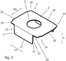
- FIG. 5 A particularly advantageous embodiment of the plug-in body 3 is shown in Figure 5 shown.
- This has a flat base body 2 with a length LG (shown by an arrow) of approx. 36 mm +/- 2 mm, a width BG (shown by an arrow) of approx. 26 mm +/- 2 mm and rounded corners 29 between the longitudinal side edges 28 and the broad side edges 30 with a radius of approximately 2 mm.
- This embodiment also has on the longitudinal side edges 28 arranged evenly in relation to the broad sides 30, flat insertable wings 3 with a width (extends in the direction of the length LG of the base body) of approx.
- the insert wings 3 are largely arranged at right angles to the base body 2.
- the side edges 32 of the insert wings 3 are beveled over a section 32 extending approximately 4 mm in length from the free end 31 in the direction of the base body 2 at an angle of 10 ° +/- 20. They also have a radius between the longitudinal edge of the free end 31 and the two side edges 32 (height direction) of approximately 1 mm.
- the plug-in body 3 also has a positioning recess 5, here a round hole.
- the diameter of the positioning recess 5 is approx. 13 mm +/- 2 mm. It is arranged in the center of the base body 2.
- the base body 2 and the insert wings 3 are formed in one piece.
- the plug-in body 2 is made as a bent shaped body, for example from a sheet metal approximately 0.5 mm +/- 0.2 mm thick.
- the plug-in body 3 could, for example, also consist of plastic or a composite material.
- Free end insert wing 11. Long hole 32. section 12. Positioning pin 33. Side edges 13th inside 14th Outside 15th Longitudinal edges 16.
- Spreader 17th Basic body construction rail 18th Free end 19th Profile leg 20th Bridges 21st Construction rail
Abstract
Description
- Die Erfindung betrifft einen Wand-und Deckenbelag mit einer Akustikpaneelfläche nach Anspruch 1, ein Verfahren zum Herstellen eines Wand-und Deckenbelags mit einer Akustikpaneelfläche nach Anspruch 10 und ein Montagesystem zum Befestigen von Akustikpaneelen nach Anspruch 14.
- Wand-und Deckenbeläge aus Paneelen werden häufig aus optischen und/oder akustischen Gründen auf eine Wand oder eine Decke eines Raumes aufgebracht. Hierfür gibt es zahlreiche Befestigungssysteme. Neuere Systeme für Wand-und Deckenbeläge verwenden zum Herstellen der Belagsfläche Paneele mit klebmittellosen Verriegelungsprofilen an den Seitenkanten, um die einzelnen Paneele besonders sicher untereinander zu verbinden. Derartige Verriegelungsprofile sind bspw. aus dem Bereich der Fußbodenbeläge bekannt.
- Zum Herstellen eines Wand-und Deckenbelags werden die einzelnen Paneele in Reihen an der Wand und hier meistens an einer entsprechenden Unterkonstruktion befestigt. Dies erfolgt beispielsweise durch Befestigungsmittel wie Schrauben oder Nägel oder auch durch Montageclips, die mit einer Konstruktionsschiene zusammenwirken und für eine weitestgehende verdeckte Befestigung, d.h. eine von der Sichtseite nicht sichtbare Befestigung der Paneele sorgen.
- Problematisch ist die Befestigung der ersten Reihe von Paneelen und der letzten Reihe von Paneelen mit ihrer jeweiligen Außenkante. Hier kann keiner der bekannten Montageclips für eine vollständig verdeckte Befestigung verwendet werden, da diese zumeist zum Eingriff in das Verriegelungsprofil ausgebildet sind oder das Paneel umgreifen. Die Paneele der ersten Reihe und die Paneele der letzten Reihe werden daher häufig im Bereich der jeweiligen Außenkante, die zur Wand, Decke oder zum Fußboden zeigt, mit einer Schraube oder einem anderen Befestigungsmittel an der Unterkonstruktion befestigt. Das Befestigungsmittel wird dabei von außen durch die Oberfläche in die Unterkonstruktion oder direkt in die Wand oder die Decke eingebracht. D. h., dass bspw. der Kopf einer Schraube oder eines Nagels an der Außenseite sichtbar ist. Hinzu kommt, dass derartige Befestigungsmittel eine unbewegliche Fixierung der Seitenkante der Paneele in Quer-und/oder Längsrichtung der Paneele erzeugen, wodurch eine vollständig schwimmende Verlegung der Paneelfläche nicht möglich ist.
- Bei Akustikpaneelen mit rückseitigem Absorber kommt erschwerend hinzu, dass die Befestigung des Befestigungsmittels durch den Absorber oder in dem Absorber häufig zu Schwierigkeiten sowohl bei der Befestigung als auch bei der akustischen Leistung des Akustikpaneels führt.
- Der Erfindung liegt die Aufgabe zugrunde einen Wand-und Deckenbelag mit einer Akustikpaneelfläche, ein Verfahren zum Herstellen eines Wand- und Deckenbelages mit einer Akustikpaneelfläche und ein Montagesystem für einen Wand- und Deckenbelag mit einer Akustikpaneelfläche bereitzustellen, wobei die Paneele der ersten und letzten Paneelreihe der Akustikpaneelfläche verdeckt befestigt und vollständig schwimmend gelagert sind.
- Die der Erfindung zugrunde liegende Aufgabe wird gelöst durch einen Wand-und Deckenbelag nach Anspruch 1, ein Verfahren zum Herstellen eines Wand- und Deckenbelags nach Anspruch 10 und ein Montagesystem nach Anspruch 14. Vorteilhafte Weiterbildungen der Erfindung sind in den Unteransprüchen angegeben. Dabei sind alle beschriebenen Merkmale für sich oder in beliebiger Kombination grundsätzlich Gegenstand der Erfindung, unabhängig von ihrer Zusammenfassung in den Ansprüchen oder deren Rückbeziehung.
- Der erfindungsgemäße Wand- und Deckenbelag mit einer Akustikpaneelfläche, die schwimmend gelagerte miteinander über korrespondierende Verriegelungsprofile klebemittellos verbundene Akustikpaneele umfasst, weist ein Montagesystem mit einem Einsteckkörper, der abschnittsweise in einem Absorber eines Akustikpaneels befestigt ist und einen Montagekörper auf, der an einer an einer Wand oder Decke befestigbaren Konstruktionsschiene angeklemmt und an dem Einsteckkörper fixiert ist.
- Ein Kerngedanke der Erfindung ist die Anordnung des Einsteckkörpers in dem Absorber des Akustikpaneels und die Fixierung des Montagekörpers an dem Einsteckkörper mit der Möglichkeit, diesen an die Konstruktionsschiene anzuklemmen.
- Der Einsteckkörper, der Montagekörper und die Konstruktionsschiene stellen das Montagesystem dar. Es ermöglicht das Akustikpaneel mit einer rückseitigen Befestigung an die Unterkonstruktion zu klemmen und zu fixieren, ohne dass an der Außenseite der Akustikpaneelfläche ein Befestigungsmittel sichtbar ist. Neben der Möglichkeit die gesamte Akustikpaneelfläche mit diesem Montagesystem zu befestigen, kann mittels des Montagesystems insbesondere die Befestigung der Akustikpaneele der ersten und letzten Paneelreihe einer Akustikpaneelfläche jeweils im Bereich der Seitenkante der jeweiligen Akustikpaneele, die an eine Wand, eine Decke oder einen Boden angrenzt, erfolgen.
- Der Einsteckkörper bildet eine feste Auflage für den Montagekörper, sodass dieser an dem weichen Absorber nicht verrutschen kann oder in diesen einsinkt, sondern eine sichere und dauerhaft exakte Position einnimmt, wodurch die hohen Ansprüche an Exaktheit und Sicherheit bei der Montage erst erfüllbar sind. Unter der Befestigung in einem Absorber wird verstanden, dass zumindest ein Abschnitt, vorzugsweise mindestens zwei Abschnitte des Einsteckkörpers in dem Absorber angeordnet und befestigt sind.
- Der Montagekörper ist das Verbindungsglied zwischen der mit der Wand oder Decke verbundenen Konstruktionsschiene und dem mit dem Akustikpaneel verbundenen Einsteckkörper. Die Fixierung des Montagekörpers an dem Einsteckkörper erfolgt bevor der Montagekörper an die Konstruktionsschiene angeklemmt wird. Unter der Fixierung ist eine Befestigung des Montagekörpers in Richtung senkrecht zur Ebene des Akustikpaneels bzw. des Absorbers zu verstehen.
- Die Konstruktionsschiene kann als gebogenes Blech ausgebildet sein. Sie weist bspw. einen im Querschnitt u-förmigen Grundkörper auf, bei dem die freien Enden der Profilschenkel des u in einem 90°-Winkel zu den Profilschenkeln nach außen abgewinkelt sind und Stege ausbilden. Die Konstruktionsschiene ist bspw. zum direkten Anschrauben an die Wand oder die Decke ausgebildet.
- Unter einem Akustikpaneel ist ein Paneel zu verstehen, das auftretenden Raumschall vermindert. Ein Akustikpaneel weist eine Trägerplatte mit einer eine Sichtseite bildenden Dekorbeschichtung und einen akustisch wirksamen Absorber an der der Sichtseite gegenüberliegenden Rückseite auf. Die Trägerplatte umfasst vorzugsweise einen Holzwerkstoff, wie eine Faserplatte oder Spanplatte, einen Mineralfaserwerkstoff, ein LVT (Luxury Vinyl Tiles), ein WPC, PPC oder BPC (Wood-Plastic-Composite, Paper-Plastic-Composite, Bambus-Plastic-Composite), ein SPC (Solid-Polymer-Core oder Stone-Polymer-Composite) oder einen Faser-Zement-Werkstoff. Die Dekorschicht kann auf Basis von Kunstharz, als Lackbeschichtung und/oder Folienbeschichtung ausgebildet sein.
- Der Absorber ist mit der Rückseite der Trägerplatte verbunden, bspw. verklebt. Der Absorber ist weich ausgebildet, wobei hierunter verstanden wird, dass der Einsteckkörper oder dazu vorgesehene Abschnitte händisch in den Absorber eingedrückt werden können. Ein vorheriges Ausformen von Ausnehmungen zum Einstecken des Einstecckörpers ist nicht notwendig. Der Absorber kann bspw. eine Holzfaserdämmplatte oder eine Steinwolleplatte sein. Auch kann der Absorber eine Mineralwollplatte, eine Schaumplatte, eine Faserplatte aus bspw. Kunststofffasern oder eine Mischform hiervon sein, die ebenfalls weich ist, d.h. derart ausgebildet ist, dass ein Einsteckkörper bei der händischen Montage der Akustikpaneele vom Monteur zumindest abschnittsweise händisch in den Absorber eingedrückt werden kann. Ein weiche Steinwollplatte im Sinne der Erfindung kann bspw. eine Rohdichte (nach EN 1602) zwischen 120 kg/m3 und 200 kg/m3, insbesondere von 150 kg/m3+/-30 kg/m3, eine Zusammendrückbarkeit dl-db (nach EN 12431) ≤ 3, insbesondere von 2,5+/-0,3 und eine Punktlast bei 5 mm Stauchung (nach EN 12430) ≥ 500, insbesondere von 600 +/- 100 aufweisen.
- Neben dem Absorber auf der Rückseite weist das Akustikpaneel akustisch wirksame Ausnehmungen (im Weiteren auch Akustikausnehmungen) in der Dekorschicht und der Trägerplatte auf, sodass auf das Paneel auftreffender Raumschall durch die Ausnehmungen in die Trägerplatte und in den Absorber eindringt und dort absorbiert wird.
- An den Seitenkanten des Akustikpaneels sind korrespondierende Verriegelungsprofile angeordnet, die die einzelnen Akustikpaneele ohne die Verwendung von Klebemitteln, d.h. klebemittellos miteinander verbinden. Die korrespondierenden Verriegelungsprofile sind bspw. als Drehprofile, Schwenkprofile und/oder vertikale Rastprofile ausgebildet. Die Akustikpaneele sind über die korrespondierenden Verriegelungsprofile an den Längsseiten der Paneele und/oder an den Querseiten miteinander verbunden. Die korrespondierenden Verriegelungsprofile verbinden die Akustikpaneele derart aneinander, dass ohne weitere Verbindungsmittel, wie bspw. Klebstoff, eine dauerhaft absatzlose (Höhenversatz zwischen den verbundenen Akustikpaneelen) und dauerhaft fugenlose (Lücke zwischen den verbundenen Paneelen) Verriegelungsverbindung entsteht.
- Die Verriegelungsprofile sind vorzugsweise an den Trägerplatten der Akustikpaneele angeordnet. Der Absorber an der Rückseite der Trägerplatten kann verriegelungsprofilfrei sein. Die Absorber von zwei miteinander verbundenen Akustikpaneelen können bspw. beabstandet zueinder angeordent sein oder auch stumpf aneinander stoßen.
- Unter der Fixierung des Montagekörpers an dem Einsteckkörper ist insbesondere zu verstehen, dass der Montagekörper senkrecht zur Ebene der Akustikpaneele unbeweglich angeordnet ist. Abhängig von der Art der Ausbildung der Fixierverbindung kann dagegen weiterhin ein Verdrehen des Montagekörpers gegenüber dem Einsteckkörper bzw. eine lineare Bewegung des Montagekörpers entlang des Einsteckkörpers möglich sein.
- Unter dem Anklemmen ist ebenfalls eine Befestigung zu verstehen, die den Montagekörper senkrecht zur Ebene des Akustikpaneels anklemmt.
- Unter einer schwimmend gelagerten Akustikpaneelfläche wird verstanden, dass diese so befestigt ist, dass sie bspw. Schrumpf- und Dehnungsbewegungen der Akustikpaneele aufgrund von Klimaschwankungen durchführen kann.
- Nach einer Weiterbildung der Erfindung weißt der Einsteckkörper einen Grundkörper und zwei Einsteckflügel auf, die insbesondere weitestgehend rechtwinklig zum Grundkörper ausgerichtet sind. Der Grundkörper ist vorzugsweise flächig als bspw. Grundplatte ausgebildet.
- Die Einsteckflügel können an gegenüberliegenden Enden des Grundkörpers angeordnet sein. Die Länge der Einsteckflügel entspricht vorzugsweise der Stärke des Absorbers bzw. ist gegenüber der Stärke des Absorbers geringfügig, d.h. ca. 1-2 mm kürzer. Hierdurch können die Einsteckflügel bis zur Rückseite der Trägerplatte in den Absorber eindringen, wodurch der Einsteckkörper mit seinem Grundkörper bspw. flächig an dem Absorber anliegt, so dass die Stabilität der Verbindung zwischen dem Absorber und dem Einstecckörper besonders hoch ist. Unter rechtwinklig wird in diesem Zusammenhang insbesondere ein Winkel von 90° +/- 2° verstanden.
- Die Einsteckflügel können bspw. als Dorne ausgebildet sein, um die händische Montage zu erleichtern. Für eine sichere Montage des Akustikpaneels im Bereich der Seitenkante ist jedoch eine ausreichend große Haltekraft zwischen dem Absorber und dem Einsteckflügel notwendig. Diese kann bspw. durch eine zusätzliche Verklebung oder auch eine entsprechende Ausformung der Dorne erreicht werden. Besonders bevorzugt sind die Einsteckflügel jedoch flächig, bspw. plattenförmig ausgebildet, wodurch unerwarteterweise eine ausreichend hohe Haftkraft zwischen der Oberfläche der Einsteckflügel und dem Absorber entsteht. Die Breite der Einsteckflügel (erstreckt sich in Längsrichtung des Grundkörpers) und die Länge des Grundkörpers können zumindest weitestgehend gleich sein. Vorzugsweise sind die Einsteckflügel jedoch gegenüber dem Grundkörper kürzer, bspw. beidseitig leicht zurückspringend angeordnet sein.
- Die freien Enden der Einsteckflügel sind vorzugsweise leicht abgeschrägt und/oder weisen einen Radius auf, um das händische Einführen des Einsteckkörpers in den Absorber zu erleichtern. Der Einsteckkörper weist vorzugsweise eine Breite von mindestens 1,5 cm, vorteilhaft von mindestens 2,3 cm, besonders vorteilhaft zwischen 1,5 cm und 3 cm, insbesondere 2,2 cm +/-0,3 mm auf.
- Gerade bei der Ausbildung des Akustikpaneels mit schlitzartigen Akustikausnehmungen sind die Einsteckkörper quer zur Längsachsenrichtung der Akustikausnehmungen in den Absorber eingesteckt, wodurch gewährleistet wird, dass die Einsteckflügel nicht bis in die Akustikausnehmungen hineinragen. Hierdurch wird zum einen eine Sichtbarkeit der Einsteckflügel durch die Akustikausnehmungen verhindert, zum anderen wird sichergestellt, dass die Einsteckflügel keine mechanische Belastung auf die Stege der Akustikausnehmungen ausüben.
- Für eine besonders kostengünstige Ausgestaltung des Wand- oder Deckenbelages ist nach einer Weiterbildung der Erfindung vorgesehen, dass die Einsteckflügel mit dem Grundkörper einstückig ausgebildet sind. So kann der Einsteckkörper beispielsweise als Biegekörper ausgebildet sein, bei dem die freien Enden des Grundkörpers umgebogen sind, insbesondere in einem Winkel von 90° +/- 2°, sodass die umgebogenen freien Enden des Grundkörpers die Einsteckflügel ausbilden.
- Wie bereits ausgeführt ist der Montagekörper zum Anklemmen an die Konstruktionsschienen ausgebildet. Besonders bevorzugt umgreift der Montagekörper hierfür mit zwei Klammerarmen einen Abschnitt der Konstruktionsschiene. Die Klammerarme sind vorzugsweise an gegenüberliegenden Seiten des Montagekörpers angeordnet. Auch ist der Montagkörper mit den Klammerarmen insbesondere einstückig ausgebildet. So können beispielsweise die freien Enden des Montagekörpers über eine entsprechende Biegung zu Klammerarmen geformt sein. Der Montagekörper ist vorteilhaft ein entsprechend gebogenes Metallblech.
- Zum Herstellen der Fixierung zwischen dem Montagekörper und dem Einsteckkörper weist der Montagekörper besonders bevorzugt eine zumindest abschnittsweise flächige Basisplatte auf, die mit einer flächigen Außenseite an einer flächigen Innenseite des Grundkörpers des Einsteckkörpers anliegt und mit einem Befestigungsmittel an einer Trägerplatte des Akustikpaneels befestigt ist. Das Befestigungsmittel ragt beispielsweise mit einem Abschnitt durch die Basisplatte des Montagekörpers und den Grundkörper des Einsteckkörpers hindurch bis in die Trägerplatte, wo es befestigt ist. Das Befestigungsmittel kann beispielsweise als Nagel, vorzugsweise jedoch als Schraube ausgebildet sein. So kann eine Schraube beispielsweise mit ihrem Schraubenkopf an der Innenseite der Basisplatte des Montagekörpers anliegen und mit ihrem Gewindeabschnitt durch die Basisplatte des Montagekörpers und den Grundkörper des Einsteckenkörpers hindurchragen und von deren Rückseite aus in die Trägerplatte eingeschraubt sein.
- Für eine besonders günstige Ausbildung der schwimmenden Lagerung der Akustikpaneelfläche ist nach einer Weiterbildung der Erfindung vorgesehen, dass der Montagekörper ein Langloch aufweist, dessen Längsachse in Richtung der Klammerarme ausgerichtet ist. Das Befestigungsmittel kann durch das Langloch ragen, sodass die Akustikpaneele bei einer Bewegung in Längsachsenrichtung des Langlochs entsprechend am Befestigungsmittel entlang rutschen können. Eine Bewegung quer zur Längsachsenrichtung des Akustikpaneels kann durch eine bewegliche Klemmung des Montagekörpers an der Konstruktionsschiene, bspw. über die Klammerarme, gewährleistet werden.
- Um das Fixieren des Montagekörpers an dem Einsteckkörper zu erleichtern, ist nach einer Weiterbildung der Erfindung vorgesehen, dass der Grundkörper des Einsteckkörpers eine Positionierausnehmung aufweist und am Montagekörper Positionierzapfen angeordnet sind, die in die Positionierausnehmung am Einsteckkörper eingreifen.
- Die Positionierausnehmung ist vorzugsweise kreisrund und bspw. zentral auf dem Grundkörper angeordnet. Neben den Positionierzapfen, die insbesondere an den Rändern der Positionierausnehmung anliegen und so eine Positionierung des Montagekörpers ermöglichen, ragt insbesondere auch das Befestigungsmittel durch die Positionierausnehmung hindurch.
- Die Anordnung der Positionierzapfen am Montagekörper erfolgt vorzugsweise derart, dass die Positionierzapfen mit einem Abschnitt ihrer Außenoberfläche an der Innenkante der Positionierausnehmung anliegen. Insofern entspricht der maximale Abstand der Positionierzapfen vorzugsweise dem Durchmesser der Positionierausnehmung, gegebenenfalls abzüglich eines minimalen Spiels um das Einführen der Zapfen in die Positionierausnehmung zu erleichtern.
- Besonders bevorzugt sind zwei Positionierzapfen derart angeordnet, dass sie an gegenüberliegenden Abschnitten der Positionierausnehmung angreifen. Insbesondere können sie auf gegenüberliegenden Seiten des Langlochs in der Basisplatte des Montagekörpers angeordnet sein. Diese Anordnung ermöglicht es, dass der Montagekörper mit den Positionierzapfen in der Positionierausnehmung drehbar gelagert ist. Die Positionierzapfen verhindern dabei eine lineare Bewegung des Montagekörpers entlang der Ebene des Grundkörpers (bspw. in Längs- oder Querachsenrichtung des Akustikpaneels).
- Auch können die Positionierzapfen als Rasten ausgebildet sein, die den Rand der Positionierausnehmung zumindest abschnittsweise umgreifen. Umgreifende Positionierzapfen können bspw. als Rastkörper ausgebildet sein, die nach dem Durchführen durch die Positionierausnehmung mit einer Raste an der Außenseite des Einsteckkörpers anliegen und eine Bewegung des Montagekörpers senkrecht zur Ebene des Montagekörpers verhindern. Derartige als Rastkörper ausgebildete Positionierzapfen können gleichzeitig als Befestigungsmittel anzusehen sein, da ggf. eine weitere Befestigung über eine Schraube, Nagel usw. nicht notwendig ist. Als Rastkörper ausgebildet Positionierzapfen ermöglichen auch weiterhin eine drehbare Lagerung des Montagekörpers an dem Einsteckkörper.
- Insbesondere bei der Ausbildung des Montagekörpers als gebogenes Metallblech kann es bspw. durch das Befestigungsmittel zu einem Verziehen des Montagekörpers kommen, wodurch das Anklemmen dieses bspw. mit den Klammerarmen an der Konstruktionsschiene erschwert wird. Um die Stabilität des Montagekörpers in Längsachsenrichtung zwischen den Klammerarmen zu erhöhen, könnten bspw. Sicken angeordnet sein. Nach einer Weiterbildung der Erfindung ist jedoch vorgesehen, dass der Montagekörper zwei Spreizer aufweist. Die Spreizer sind insbesondere flächig ausgebildet und können ebenfalls als Biegeabschnitte der Basisplatte ausgeformt sein. Sie sind vorzugsweise an den sich gegenüberliegenden Längsseitenkanten der Basisplatte angeordnet und stehen senkrecht zur Ebene der Basisplatte hervor, bspw. in Richtung der Klemmarme.
- Weiter wird die Aufgabe der Erfindung gelöst durch ein Verfahren zum Herstellen eines Decken- und Wandbelages, umfassend eine schwimmend gelagerte Akustikpaneelfläche mit Akustikpaneelen, die an den Längsseiten und/oder den Querseiten mittels zueinander korrespondierender Verriegelungsprofile klebemittellos miteinander verbunden werden, mit den Schritten:
- Befestigen eines Einsteckkörpers in einer vorgegebenen Position in einen Absorber eines Akustikpaneels,
- Anlegen eines Montagekörpers an den Einsteckkörper,
- Fixieren des Montagekörpers an dem Einsteckkörper
- Anklemmen des Montagekörpers an eine an einer Wand oder Decke angeordneten Konstruktionsschiene.
- Gerade bei Akustikpaneelen, die mittels korrespondierender Verriegelungsprofile klebemittelos verbunden werden, besteht bei bspw. einem unbeabsichtigten Ablösen der Seitenkante ein hohes Risiko für einen Dominoeffekt, bei dem das sich ablösende Akustikpaneel die über die Verriegelungsverbindungen verbundenen weiteren Akustikpaneele von der Wand oder Decke herunterzieht. Das Verfahren ermöglicht eine besonders geschützte Verbindung der Akustikpaneele der ersten und letzten Paneelreihe einer Paneelfläche im Bereich der Seitenkante, wodurch das unbeabsichtigte Ablösen der Paneele im Bereich der Seitenkanten vermieden und somit auch Dominoeffekte verhindert werden. Zudem ermöglicht das Verfahren, wie auch der Wand und Deckenbelag und das Montagesystem gleichzeitig eine vollständige verdeckte und somit nicht sichtbare Befestigung der Akustikpaneele, die außerdem eine schwimmende Lagerung der Akustikpaneelfläche ermöglicht. Wie bereits zum Wand- und Deckenbelag ausgeführt, wird unter der Seitenkante der Akustikpaneele die Seitenkante der Akustikpaneeler der ersten und letzten Paneelreihe verstanden, die zu einer an die Akustikpaneelfläche angrenzenden Wand, Decke oder zu einem Boden zeigt. Unter der verdeckten Befestigung ist eine auf der Sichtseite der Akustikpaneele nicht sichtbare Befestigung an einer Wand/Decke oder Unterkonstruktion zu verstehen.
- Zum Befestigen des Einsteckkörpers wird dieser nach einer Weiterbildung der Erfindung in den Absorber eingesteckt. Das Einstecken erfolgt vorzugsweise händisch, bspw. durch den die Paneelfläche montierenden Monteur. Die vorgegebene Position ergibt sich dabei durch die an der Wand oder Decke angebrachten Konstruktionsschienen, mittels der der Monteur die richtige Position an der Rückseite des Akustikpaneels bestimmen kann.
- Beim Anlegen wird der Montagekörper bspw. mit einem flächigen Abschnitt an einen flächigen Abschnitt des Einsteckkörpers angelegt. Anschließend wird ein Befestigungsmittel mit einem Abschnitt durch den Montagekörper und den Grundkörper des Einsteckkörpers geführt und durch den Absorber in einer Trägerplatte des Akustikpaneels befestigt, bspw. eingeschraubt.
- Um eine ausreichende Beweglichkeit der Akustikpaneele am Montagekörper zu gewährleisten, bspw. damit das Akustikpaneel Schrumpf-und Dehnungsbewegungen aufgrund von Klimaschwanken durchführen kann, ist nach einer Weiterbildung der Erfindung vorgesehen, dass das Befestigungsmittel mit einem Abschnitt durch ein Langloch in dem Montagekörper und durch eine Positionierausnehmung im Einsteckkörper geführt und mit der Trägerplatte verbunden wird. Das Langloch ermöglicht somit eine Bewegung des Akustikpaneels bspw. in seine Längsachsenrichtung. Die Fixierung erfolgt somit vorzugsweise durch ein Anpressen des Montagekörpers an dem Einsteckkörper bspw. mittels des Befestigungsmittels.
- Nach dem Befestigen des Montagekörpers wird dieser mit dem Paneel an die Konstruktionsschiene geklemmt. Besonders bevorzugt fassen zum Anklemmen des Montagekörpers an der Konstruktionsschiene zwei Klammerarme des Montagekörpers um einen Abschnitt der Konstruktionsschiene herum. Hierdurch können die Akustikpaneele besonders einfach mittels händischem Druck ausgehend von der Sichtseite gegen die Konstruktionsschiene gedrückt werden, um bspw. um einen Abschnitt der Konstruktionsschiene zu schnappen. D.h., in der montierten Position umfassen die Klammerarme einen Abschnitt der Konstruktionsschiene und halten das Akustikpaneel dauerhaft und sicher in Position. Durch das Umgreifen der Konstruktionsschiene wird zudem eine in Längsachsenrichtung der Konstruktionsschiene bewegliche Lagerung besonders einfach ermöglicht und dauerhaft gewährleistet.
- Eine weitere Lösung der Aufgabe wird durch ein Montagesystem zum verdeckten Befestigen von Akustikpaneelen an einer Wand oder Decke bereitgestellt, wobei die Akustikpaneele über Verriegelungsprofile miteinander verbunden sind, umfassend einen Einsteckkörper zum Einstecken in einen Absorber des Akustikpaneels und einen Montagekörper zum Fixieren an dem Einsteckkörper und zum Anklemmen an eine an der Wand oder Decke befestigbare Konstruktionsschiene.
- Der Montagekörper ist dabei in Längsachsenrichtung der Konstruktionsschiene beweglich angeklemmt, während der Einsteckkörper mit dem Paneel insbesondere quer zur Längsachsenrichtung am Montagekörper fixiert ist.
- Mittels des Montagesystems können die Seitenkanten einer Akustikpaneelfläche verdeckt an einer Unterkonstruktion befestigt werden und es wird auf einfache Weise eine vollständige schwimmende Lagerung der aus den Akustikpaneelen gebildeten Akustikpaneelfläche ermöglicht. Es verhindert zudem von den Seitenkanten ausgehende Dominoeffekte.
- Obwohl manche Aspekte im Zusammenhang mit einem Wand-und Deckenbelag beschrieben wurden, versteht es sich, dass diese Aspekte auch eine Beschreibung des entsprechenden Verfahrens bzw. des Montagesystems darstellen, sodass ein Block- oder ein Bauelement des Wand- und Deckenbelages auch als ein entsprechender Verfahrensschritt, als ein Merkmal eines Verfahrensschrittes oder Merkmal des Montagesystems zu verstehen ist. Analog dazu stellen Aspekte, die im Zusammenhang mit einem oder als ein Verfahrensschritt oder als Merkmal des Montagesystems beschrieben wurden, auch eine Beschreibung eines entsprechenden Blocks oder Details oder Merkmals einer entsprechenden Vorrichtung dar. Dementsprechend kann auch ein im Zusammenhang mit dem Montagesystem beschriebenes Block- oder Bauelement als ein Verfahrensschritt, ein Merkmal eines Verfahrensschrittes oder ein Merkmal des Wand-und Deckenbelages zu verstehen sein.
- Im Weitern wird die Erfindung anhand von Ausführungsbeispiels näher beschrieben. Es zeigt:
- Fig. 1
- schematisch in perspektivischer Darstellung einen Einsteckkörper zum Einbringen in einen Absorber;
- Fig. 2
- schematisch in einer perspektivischen Darstellung einen Montagekörper zum Fixieren an einem Einsteckkörper und Anklemmen an einer Konstruktionsschiene;
- Fig. 3
- schematisch in einer perspektivischen Darstellung eine Konstruktionsschiene zum Befestigen an einer Wand oder Decke und zum Anklemmen des Montagekörpers;
- Fig.4
- schematisch und in einer Ansicht einen Wand- und Deckenbelag mit einer Akustikpaneelfläche;
- Fig.5
- schematisch in einer perspektivischen Darstellung eine vorteilhafte Ausführungsform eines Einsteckkörpers.
-
Figur 1 zeigt schematisch in einer perspektivischen Darstellung einen Einsteckkörper 1 mit einem Grundkörper 2 und zwei Einsteckflügeln 3. Der Einsteckkörper 1 ist als Biegekörper ausgebildet, bei dem die freien Enden 6 des Grundkörpers 2 abgekantet wurden und jetzt die beiden Einsteckflügel 3 ausbilden. Die Einsteckflügel 3 sind an zwei gegenüberliegenden Enden des Grundkörpers 2 angeordnet. Vom Grundkörper 2 ist die Innenseite 13 sichtbar. Die Einsteckflügel 3 und der Grundkörper 2 sind jeweils flächig, hier plattenförmig, ausgebildet. Der Winkel α zwischen jedem Einsteckflügel 3 und dem Grundkörper 2 beträgt jeweils 90° +/- 2°. Die freien Enden 6 der Einsteckflügel 3 zeigen in die gleiche Richtung. Die Einsteckflügel 3 weisen jeweils leichte Abschrägungen 4 an ihren freien Enden 6 auf, um das Einstecken in den Absorber (hier nicht dargestellt) zu erleichtern. Der Einsteckkörper 3 ist aus einem Metallblech geformt. Der Grundkörper 2 und die Einsteckflügel 3 sind einstückig ausgebildet. - Im Grundkörper 2 ist eine Positionierausnehmung 5 eingebracht. Die Positionierausnehmung 5 ist kreisrund und hier um den Flächenmittelpunkt (hier nicht dargestellt) des Grundkörpers 2 angeordnet.
-
Figur 2 zeigt schematisch in einer perspektivischen Darstellung einen Montagekörper 7 mit einer Basisplatte 8 und zwei zu Klammerarmen 9 gebogenen freien Enden 10 der Basisplatte 8. Gut sichtbar ist eine Innenseite 13 des Montagekörpers 7, die im montierten Zustand in Richtung der Konstruktionsschiene 21 zeigt. - Der Abstand zwischen den Klammerarmen 9 und somit auch die Länge der Basisplatte 8 sind auf die Breite der Konstruktionsschiene abgestimmt und darauf ausgelegt, um die freien Enden 18 (
Figur 3 ) der Konstruktionsschiene 21 herumzugreifen. - In die Basisplatte 8 ist mittig ein Langloch 11 eingebracht, das zum Durchführen eines Befestigungsmittels (hier nicht dargestellt) vorgesehen ist. In Querachsenrichtung Q, jeweils auf gegenüberliegenden Seiten des Langlochs 11 sind Positionierzapfen 12 angeordnet. Die Positionierzapfen 12 sind an der Innenseite 13 als runde Löcher dargestellt, während sich die zapfenartigen Erhebungen (hier nicht dargestellt) aus der Außenseite 14 erstrecken.
- Weiter weist die Basisplatte 8 zwei Spreizer 16 auf, die jeweils an gegenüberliegenden Längskanten 15 der Basisplatte 8 angeordnet sind und die Stabilität der Basisplatte 8 erhöhen. Die Spreizer 16 sind flächig ausgebildet. Sie wurden durch ein Umbiegen von Abschnitten der Basisplatte 8 erzeugt. Die Basisplatte 8, die Spreizer 16 und die Klammerarme 9 sind somit einstückig ausgebildet.
-
Figur 3 zeigt eine Konstruktionsschiene 21, die als gebogenes Blech ausgebildet ist. Die Konstruktionsschiene 21 weist im Querschnitt einen u-förmigen Grundkörper 17 auf. Die freien Enden 18 der Profilschenkel 19 des u sind in einem 90°-Winkel vom Profilschenkel 19 abgewinkelt und bilden Stege 20 aus. Die beiden Stege 20 sind zum Umgreifen der Klammerarme 9 des Montagekörpers 7 ausgebildet. Die Konstruktionsschiene 21 weist zudem Löcher 22 auf, die bspw. zum Anschrauben der Konstruktionsschiene 21 an einer Wand oder einer Decke (hier nicht dargestellt) vorgesehen sind. - Im montierten Zustand greifen die Klammerarme 9 um die Stege 20 und klemmen den Montagekörper 7 an der Konstruktionsschiene 21 an. Der dabei erzeugte Klammerdruck verhindert das unbeabsichtigte Ablösen des Montagekörpers 7 von der Konstruktionsschiene 21 in Richtung senkrecht zur Ebene der Konstruktionsschiene, bzw. senkrecht zur Ebene des zu montierenden Akustikpaneels 23 (siehe
Figur 4 ), ist jedoch derart ausgebildet, dass der Montagekörper 7 in Längsachsenrichtung der Konstruktionsschiene 21 beweglich bleibt. Im Zusammenspiel mit dem Langloch 11 in der Basisplatte 8 wird eine vollständig schwimmende Lagerung der Akustikpaneele 23 der ersten und letzten Akustikpaneelreihe 25, 26 (sieheFigur 4 ) ermöglicht. -
Figur 4 zeigt schematisch in einer Ansicht eine Akustikpaneelfläche 22 aus einzelnen über Verriegelungsprofile (hier nicht dargestellt) klebemittelos verbundenen Akustikpaneelen 23, die als Wand- oder Deckenbelag 24 verwendbar ist. - Die erste und letzte Paneelreihe 25, 26 grenzen mit ihrer äußersten Seitenkante 27 jeweils an eine Wand, Decke oder einen Boden (hier nicht dargestellt) an.
- Weiter sind Konstruktionsschienen 21 (hier durch gestrichelte Linie dargestellt) angedeutet, die an der Wand oder Decke befestigt und hinter der Akustikpaneelfläche 22 angeordnet sind. Die Akustikpaneelfläche 22 ist zumindest mit ihren Seitenkanten 27 mittels des Einsteckkörpers 1 und des Montagekörpers 7 an der Konstruktionsschiene 21 befestigt und bspw. durch die bewegliche Fixierung des Montagekörpers 7 am Einsteckkörper 1 im Bereich der Seitenkanten 27 vollständig schwimmend gelagert.
- Eine besonders vorteilhafte Ausführungsform des Einsteckkörpers 3 wird in
Figur 5 gezeigt. Diese weist einen flächigen Grundkörper 2 mit einer Länge LG (durch einen Pfeil dargestellt) von ca. 36 mm +/-2 mm, einer Breite BG (durch einen Pfeil dargestellt) von ca. 26 mm +/-2 mm und abgerundete Ecken 29 zwischen den Längsseitenkanten 28 und den Breitseitenkanten 30 mit einem Radius von ca. 2 mm auf. Diese Ausführungsform weist zudem an den Längseitenkanten 28 angeordente gleichmäßig gegenüber den Breitseiten 30 zurückspringende flächige Einsteckflügel 3 mit einer Breite (erstreckt sich in Richtung der Länge LG des Grundkörpers) von ca. 23 mm +/- 2 mm und einer Höhe H (durch einen Pfeil dargestellt, erstreckt sich ausgehend von dem Grundkörper 2 in Richtung des freien Endes 31) von ca. 10 mm +/-1 mm auf. Die Einsteckflügel 3 sind weitestgehend rechtwinklig zum Grundkörper 2 angeordent. Die Seitenkanten 32 der Einsteckflügel 3 sind dabei über einen sich ca. 4 mm lang erstreckenden Abschnitt 32 ausgehend vom freien Ende 31 in Richtung des Grundkörpers 2 mit einem Winkel von 10° +/- 20 angeschrägt. Sie weisen zudem einen Radius zwischen der Längskante des freien Endes 31 und den beiden Seitenkanten 32 (Höhenrichtung) von ca. 1 mm auf. - Weiter weist der Einsteckkörper 3 eine Positionierausnehmung 5, hier ein rundes Loch, auf. Der Durchmesser der Positionierausnehmung 5 beträgt ca. 13 mm +/- 2 mm. Sie ist mittig im Grundkörper 2 angeordnet.
- Der Grundkörper 2 und die Einsteckflügel 3 sind einstückig ausgebildet. Hier ist der Einsteckkörper 2 als Biegeformkörper, bspw. aus einem ca. 0,5 mm +/- 0,2 mm starken Metallblech hergestellt. Alternativ könnte der Einsteckkörper 3 jedoch bspw. auch aus Kunststoff oder einem Kompositwerkstoff bestehen.
Bezugszeichenliste 1. Einsteckkörper 22. Akustikpaneelfläche 2. Grundkörper 23. Akustikpaneel 3. Einsteckflügel 24. Wand-und Deckenbelag 4. Abschrägungen 25. erste Paneelreihe 5. Positionierausnehmung 26. letzte Paneelreihe 6. Freies Ende 27. Seitenkante 7. Montagekörper 28. Längsseitenkante Grundkörper 8. Basisplatte 29. Ecken Grundkörper 9. Klammerarmen 30. Breitenkante Grundkörper 10. Freies Ende 31. Freies Ende Einsteckflügel 11. Langloch 32. Abschnitt 12. Positionierzapfen 33. Seitenkanten 13. Innenseite 14. Außenseite 15. Längskanten 16. Spreizer 17. Grundkörper Konstruktionsschiene 18. Freies Ende 19. Profilschenkel 20. Stege 21. Konstruktionsschiene L Längsachsenrichtung Montagekörper Q Querachsenrichtung Montagekörper LK Längsachsenrichtung Konstruktionsschiene LG Länge Grundkörper BG Breite Grundkörper H Höhe Einsteckflügel
Claims (14)
- Wand- und Deckenbelag mit einer Akustikpaneelfläche (22), die schwimmend gelagert ist und miteinander über korrespondierende Verriegelungsprofile klebemittelos verbundene Akustikpaneele (23) umfasst, aufweisend ein Montagesystem mit- einem Einsteckkörper (1), der abschnittsweise in einem Absorber eines der Akustikpaneele (23) befestigt ist- und einem Montagekörper (7), der an eine an einer Wand oder Decke befestigbaren Konstruktionsschiene (21) angeklemmt und an dem Einsteckkörper (1) fixiert ist.
- Wand- und Deckenbelag nach Anspruch 1, dadurch gekennzeichnet, dass der Einsteckkörper (1) einen Grundkörper (2) und zwei Einsteckflügel (3) aufweist, wobei die Einsteckflügel (3) insbesondere weitestgehend rechtwinklig zum Grundkörper (2) ausgerichtet sind.
- Wand- und Deckenbelag nach mindestens einem der vorhergehenden Ansprüche, dadurch gekennzeichnet, dass die Einsteckflügel (3) flächig ausgebildet sind und quer zu Akustikausnehmungen des Akustikpaneels (23) angeordnet sind.
- Wand- und Deckenbelag nach mindestens einem der vorhergehenden Ansprüche, dadurch gekennzeichnet, dass die Einsteckflügel (3) einstückig mit dem Grundkörper (2) ausgebildet sind.
- Wand- und Deckenbelag nach mindestens einem der vorhergehenden Ansprüche, dadurch gekennzeichnet, dass der Montagkörper (7) mit zwei Klammerarmen (9) die Konstruktionsschiene (21) umgreift.
- Wand- und Deckenbelag nach mindestens einem der vorhergehenden Ansprüche, dadurch gekennzeichnet, dass der Montagekörper (7) eine zumindest abschnittsweise flächige Basisplatte (8) aufweist, die mit einer flächigen Außenseite (14) an einem flächigen Abschnitt des Grundkörpers (2) des Einsteckkörpers (3) anliegt und mit einem Befestigungsmittel an einer Trägerplatte des Akustikpaneels (23) befestigt ist.
- Wand- und Deckenbelag nach mindestens einem der vorhergehenden Ansprüche, dadurch gekennzeichnet, dass der Montagekörper (7) ein Langloch (11) aufweist, dessen Längsachse in Richtung der Klammerarme (9) ausgerichtet ist.
- Wand- und Deckenbelag nach mindestens einem der vorhergehenden Ansprüche, dadurch gekennzeichnet, dass der Grundkörper (2) des Einsteckkörpers (1) eine Positionierausnehmung (5) aufweist und am Montagekörper (7) Positionierzapfen (12) angeordnet sind, die in die Positionierausnehmung (5) am Einsteckkörper (1) eingreifen.
- Wand- und Deckenbelag nach mindestens einem der vorhergehenden Ansprüche, dadurch gekennzeichnet, dass der Montagekörper (7) zwei Spreizer (16) zum Erhöhen der Stabilität aufweist, wobei die Spreizer (16) flächig ausgebildet sind und sich mit ihrer Ebene quer zur Ebene der Basisplatte (8) des Montagekörpers (7) ausgerichtet sind.
- Verfahren zum Herstellen eines Decken- und Wandbelages, umfassend eine schwimmend gelagerte Akustikpaneelfläche (22) mit Akustikpaneelen (23), die an den Längsseiten und/oder den Querseiten mittels zueinander korrespondierender Verriegelungsprofile klebemittellos miteinander verbunden werden, mit den Schritten:- Befestigen eines Einsteckkörpers (3) in einer vorgegebenen Position in einem Absorber eines Akustikpaneels (23),- Anlegen eines Montagekörpers (7) an den Einsteckkörper (1),- Fixieren des Montagekörpers (7) an dem Einsteckkörper (1),- Anklemmen des Montagekörpers (7) an eine an einer Wand oder Decke angeordnete Konstruktionsschiene (21).
- Verfahren nach Anspruch 10 dadurch gekennzeichnet, dass der Einsteckkörper (1) in den Absorber eingesteckt wird.
- Verfahren nach Anspruch 10 oder Anspruch 11, dadurch gekennzeichnet, dass ein Befestigungsmittel durch ein Langloch (11) in dem Montagekörper (7) und durch eine Positionierausnehmung (5) in dem Einsteckkörper geführt und mit einer Trägerplatte verbunden wird.
- Verfahren nach mindestens einem der Ansprüche 10 bis 12, dadurch gekennzeichnet, dass zum Anklemmen zwei Klemmarme (9) des Montagekörpers (7) um einen Abschnitt der Konstruktionsschiene (21) fassen und den Montagkörper (7) an der Konstruktionsschiene (21) fixieren.
- Montagesystem zum verdeckten Befestigen von Akustikpaneelen an einer Wand oder Decke, wobei die Akustikpaneele (23) über Verriegelungsprofile miteinander verbunden sind, umfassend einen Einsteckkörper (1) zum Einstecken in einen Absorber des Akustikpaneels (23) und einen Montagekörper (7) zum Fixieren an dem Einsteckkörper (1) und zum Anklemmen an eine an der Wand oder Decke befestigbare Konstruktionsschiene (21).
Priority Applications (4)
| Application Number | Priority Date | Filing Date | Title |
|---|---|---|---|
| ES19157289T ES2874662T3 (es) | 2019-02-14 | 2019-02-14 | Revestimiento de pared y techo que comprende paneles acústicos |
| PL19157289T PL3696341T3 (pl) | 2019-02-14 | 2019-02-14 | Okładzina ścienna i sufitowa z paneli akustycznych |
| EP19157289.0A EP3696341B1 (de) | 2019-02-14 | 2019-02-14 | Wand- und deckenbelag aus akustikpaneelen |
| PT191572890T PT3696341T (pt) | 2019-02-14 | 2019-02-14 | Revestimento de parede e de teto constituído por painéis acústicos |
Applications Claiming Priority (1)
| Application Number | Priority Date | Filing Date | Title |
|---|---|---|---|
| EP19157289.0A EP3696341B1 (de) | 2019-02-14 | 2019-02-14 | Wand- und deckenbelag aus akustikpaneelen |
Publications (2)
| Publication Number | Publication Date |
|---|---|
| EP3696341A1 true EP3696341A1 (de) | 2020-08-19 |
| EP3696341B1 EP3696341B1 (de) | 2021-03-31 |
Family
ID=65440919
Family Applications (1)
| Application Number | Title | Priority Date | Filing Date |
|---|---|---|---|
| EP19157289.0A Active EP3696341B1 (de) | 2019-02-14 | 2019-02-14 | Wand- und deckenbelag aus akustikpaneelen |
Country Status (4)
| Country | Link |
|---|---|
| EP (1) | EP3696341B1 (de) |
| ES (1) | ES2874662T3 (de) |
| PL (1) | PL3696341T3 (de) |
| PT (1) | PT3696341T (de) |
Citations (5)
| Publication number | Priority date | Publication date | Assignee | Title |
|---|---|---|---|---|
| EP2003258A2 (de) * | 2007-05-18 | 2008-12-17 | Plakabeton S.A. | Befestigungsvorrichtung mit akustischer Isolierung zur Verwendung im Gebäudebau |
| DE102009021904A1 (de) * | 2009-05-19 | 2010-12-30 | Michael Hanssen | Installationssystem zur Vorwandmontage, und Verfahren zur Herstellung |
| DE102014207852A1 (de) * | 2013-04-26 | 2014-10-30 | Holzwerke Ladenburger GmbH & Co. KG | Akustikabsorber-Bauelement |
| CN204001528U (zh) * | 2014-04-29 | 2014-12-10 | 张升锋 | 一种布艺吸声装置 |
| US20170044772A1 (en) * | 2015-08-12 | 2017-02-16 | Shraga Gestetner | Wall covering |
-
2019
- 2019-02-14 PT PT191572890T patent/PT3696341T/pt unknown
- 2019-02-14 ES ES19157289T patent/ES2874662T3/es active Active
- 2019-02-14 EP EP19157289.0A patent/EP3696341B1/de active Active
- 2019-02-14 PL PL19157289T patent/PL3696341T3/pl unknown
Patent Citations (5)
| Publication number | Priority date | Publication date | Assignee | Title |
|---|---|---|---|---|
| EP2003258A2 (de) * | 2007-05-18 | 2008-12-17 | Plakabeton S.A. | Befestigungsvorrichtung mit akustischer Isolierung zur Verwendung im Gebäudebau |
| DE102009021904A1 (de) * | 2009-05-19 | 2010-12-30 | Michael Hanssen | Installationssystem zur Vorwandmontage, und Verfahren zur Herstellung |
| DE102014207852A1 (de) * | 2013-04-26 | 2014-10-30 | Holzwerke Ladenburger GmbH & Co. KG | Akustikabsorber-Bauelement |
| CN204001528U (zh) * | 2014-04-29 | 2014-12-10 | 张升锋 | 一种布艺吸声装置 |
| US20170044772A1 (en) * | 2015-08-12 | 2017-02-16 | Shraga Gestetner | Wall covering |
Also Published As
| Publication number | Publication date |
|---|---|
| PT3696341T (pt) | 2021-06-09 |
| PL3696341T3 (pl) | 2021-10-18 |
| ES2874662T3 (es) | 2021-11-05 |
| EP3696341B1 (de) | 2021-03-31 |
Similar Documents
| Publication | Publication Date | Title |
|---|---|---|
| EP3321441B1 (de) | Klammersystem für paneele | |
| EP1036244B1 (de) | Platten- oder leistenförmige Bauteile | |
| DE2908153C2 (de) | ||
| DE102010051388B4 (de) | Verbindungsanordnung | |
| DE102013225173A1 (de) | Montageprofil für plattenförmige Module | |
| DE2610998B2 (de) | Halterung zur Befestigung von Bekleidungsplatten vor einer Bauwerkswand | |
| EP3696341B1 (de) | Wand- und deckenbelag aus akustikpaneelen | |
| DE3239485A1 (de) | U-foermiges anschlussstueck fuer wandelemente | |
| DE2501330C3 (de) | Wand mit einem aus stabförmigen Bauelementen zusammengesetzten Traggerippe | |
| DE102016118491A1 (de) | Verfahren zur Montage von Isolierplatten an einer Gebäudewand und Satz von Elementen zur Montage von Isolierplatten an einer Gebäudewand | |
| DE69923565T2 (de) | Verbindungsstruktur für vielfältige Teile | |
| EP1709887A2 (de) | Leisteneckverkleidung | |
| EP0027196B1 (de) | Verkleidungsaufbau mit Klemmvorrichtung und Verkleidungsteil | |
| DE3015961A1 (de) | Bausatz zur lagefixierung von halteklipsen fuer rohrschlangen, insbesondere bei fussbodenheizungen | |
| WO2008049540A1 (de) | Befestigungssystem und verfahren zur rand- und/oder eckbefestigung eines paneels | |
| DE19730203A1 (de) | Überhangstreifen für ein Anschlußblech für Gebäude | |
| DE102009016917B3 (de) | Montage-Hilfswerkzeug und Verfahren zur Montage von Bauplatten an eine Unterkonstruktion | |
| DE19744340A1 (de) | Modulares Verkleidungssystem | |
| DE8516815U1 (de) | Befestigungselement | |
| DE202021106266U1 (de) | Verbinder und ALC-Montageknotenstruktur | |
| DE10345629B4 (de) | Vorrichtung zum Einspannen eines nicht-elastischen Bauteils | |
| EP1914358A2 (de) | Montagehilfsmittel | |
| WO2020127770A1 (de) | Montageclip zur schwimmenden lagerung von wand- und deckenpaneelen | |
| EP4041963A1 (de) | Bauelement mit stromschienensystem und gebäude mit bauelement sowie verfahren zur herstellung eines bauelements | |
| DE202017102838U1 (de) | Montageklammern für Paneele für ein dreidimensionales Dekor von Wand- und Deckenpaneelen |
Legal Events
| Date | Code | Title | Description |
|---|---|---|---|
| PUAI | Public reference made under article 153(3) epc to a published international application that has entered the european phase |
Free format text: ORIGINAL CODE: 0009012 |
|
| STAA | Information on the status of an ep patent application or granted ep patent |
Free format text: STATUS: REQUEST FOR EXAMINATION WAS MADE |
|
| 17P | Request for examination filed |
Effective date: 20191001 |
|
| AK | Designated contracting states |
Kind code of ref document: A1 Designated state(s): AL AT BE BG CH CY CZ DE DK EE ES FI FR GB GR HR HU IE IS IT LI LT LU LV MC MK MT NL NO PL PT RO RS SE SI SK SM TR |
|
| AX | Request for extension of the european patent |
Extension state: BA ME |
|
| GRAP | Despatch of communication of intention to grant a patent |
Free format text: ORIGINAL CODE: EPIDOSNIGR1 |
|
| STAA | Information on the status of an ep patent application or granted ep patent |
Free format text: STATUS: GRANT OF PATENT IS INTENDED |
|
| INTG | Intention to grant announced |
Effective date: 20201103 |
|
| GRAS | Grant fee paid |
Free format text: ORIGINAL CODE: EPIDOSNIGR3 |
|
| GRAA | (expected) grant |
Free format text: ORIGINAL CODE: 0009210 |
|
| STAA | Information on the status of an ep patent application or granted ep patent |
Free format text: STATUS: THE PATENT HAS BEEN GRANTED |
|
| AK | Designated contracting states |
Kind code of ref document: B1 Designated state(s): AL AT BE BG CH CY CZ DE DK EE ES FI FR GB GR HR HU IE IS IT LI LT LU LV MC MK MT NL NO PL PT RO RS SE SI SK SM TR |
|
| REG | Reference to a national code |
Ref country code: GB Ref legal event code: FG4D Free format text: NOT ENGLISH Ref country code: CH Ref legal event code: EP |
|
| REG | Reference to a national code |
Ref country code: DE Ref legal event code: R096 Ref document number: 502019001072 Country of ref document: DE Ref country code: AT Ref legal event code: REF Ref document number: 1377075 Country of ref document: AT Kind code of ref document: T Effective date: 20210415 |
|
| REG | Reference to a national code |
Ref country code: IE Ref legal event code: FG4D Free format text: LANGUAGE OF EP DOCUMENT: GERMAN |
|
| REG | Reference to a national code |
Ref country code: PT Ref legal event code: SC4A Ref document number: 3696341 Country of ref document: PT Date of ref document: 20210609 Kind code of ref document: T Free format text: AVAILABILITY OF NATIONAL TRANSLATION Effective date: 20210604 |
|
| REG | Reference to a national code |
Ref country code: NL Ref legal event code: FP |
|
| REG | Reference to a national code |
Ref country code: SE Ref legal event code: TRGR |
|
| REG | Reference to a national code |
Ref country code: LT Ref legal event code: MG9D |
|
| PG25 | Lapsed in a contracting state [announced via postgrant information from national office to epo] |
Ref country code: NO Free format text: LAPSE BECAUSE OF FAILURE TO SUBMIT A TRANSLATION OF THE DESCRIPTION OR TO PAY THE FEE WITHIN THE PRESCRIBED TIME-LIMIT Effective date: 20210630 Ref country code: BG Free format text: LAPSE BECAUSE OF FAILURE TO SUBMIT A TRANSLATION OF THE DESCRIPTION OR TO PAY THE FEE WITHIN THE PRESCRIBED TIME-LIMIT Effective date: 20210630 Ref country code: FI Free format text: LAPSE BECAUSE OF FAILURE TO SUBMIT A TRANSLATION OF THE DESCRIPTION OR TO PAY THE FEE WITHIN THE PRESCRIBED TIME-LIMIT Effective date: 20210331 Ref country code: HR Free format text: LAPSE BECAUSE OF FAILURE TO SUBMIT A TRANSLATION OF THE DESCRIPTION OR TO PAY THE FEE WITHIN THE PRESCRIBED TIME-LIMIT Effective date: 20210331 |
|
| PG25 | Lapsed in a contracting state [announced via postgrant information from national office to epo] |
Ref country code: LV Free format text: LAPSE BECAUSE OF FAILURE TO SUBMIT A TRANSLATION OF THE DESCRIPTION OR TO PAY THE FEE WITHIN THE PRESCRIBED TIME-LIMIT Effective date: 20210331 Ref country code: RS Free format text: LAPSE BECAUSE OF FAILURE TO SUBMIT A TRANSLATION OF THE DESCRIPTION OR TO PAY THE FEE WITHIN THE PRESCRIBED TIME-LIMIT Effective date: 20210331 |
|
| PG25 | Lapsed in a contracting state [announced via postgrant information from national office to epo] |
Ref country code: SM Free format text: LAPSE BECAUSE OF FAILURE TO SUBMIT A TRANSLATION OF THE DESCRIPTION OR TO PAY THE FEE WITHIN THE PRESCRIBED TIME-LIMIT Effective date: 20210331 Ref country code: EE Free format text: LAPSE BECAUSE OF FAILURE TO SUBMIT A TRANSLATION OF THE DESCRIPTION OR TO PAY THE FEE WITHIN THE PRESCRIBED TIME-LIMIT Effective date: 20210331 Ref country code: CZ Free format text: LAPSE BECAUSE OF FAILURE TO SUBMIT A TRANSLATION OF THE DESCRIPTION OR TO PAY THE FEE WITHIN THE PRESCRIBED TIME-LIMIT Effective date: 20210331 Ref country code: LT Free format text: LAPSE BECAUSE OF FAILURE TO SUBMIT A TRANSLATION OF THE DESCRIPTION OR TO PAY THE FEE WITHIN THE PRESCRIBED TIME-LIMIT Effective date: 20210331 |
|
| REG | Reference to a national code |
Ref country code: ES Ref legal event code: FG2A Ref document number: 2874662 Country of ref document: ES Kind code of ref document: T3 Effective date: 20211105 |
|
| PG25 | Lapsed in a contracting state [announced via postgrant information from national office to epo] |
Ref country code: SK Free format text: LAPSE BECAUSE OF FAILURE TO SUBMIT A TRANSLATION OF THE DESCRIPTION OR TO PAY THE FEE WITHIN THE PRESCRIBED TIME-LIMIT Effective date: 20210331 Ref country code: RO Free format text: LAPSE BECAUSE OF FAILURE TO SUBMIT A TRANSLATION OF THE DESCRIPTION OR TO PAY THE FEE WITHIN THE PRESCRIBED TIME-LIMIT Effective date: 20210331 Ref country code: IS Free format text: LAPSE BECAUSE OF FAILURE TO SUBMIT A TRANSLATION OF THE DESCRIPTION OR TO PAY THE FEE WITHIN THE PRESCRIBED TIME-LIMIT Effective date: 20210731 |
|
| REG | Reference to a national code |
Ref country code: DE Ref legal event code: R097 Ref document number: 502019001072 Country of ref document: DE |
|
| PG25 | Lapsed in a contracting state [announced via postgrant information from national office to epo] |
Ref country code: DK Free format text: LAPSE BECAUSE OF FAILURE TO SUBMIT A TRANSLATION OF THE DESCRIPTION OR TO PAY THE FEE WITHIN THE PRESCRIBED TIME-LIMIT Effective date: 20210331 Ref country code: AL Free format text: LAPSE BECAUSE OF FAILURE TO SUBMIT A TRANSLATION OF THE DESCRIPTION OR TO PAY THE FEE WITHIN THE PRESCRIBED TIME-LIMIT Effective date: 20210331 |
|
| PLBE | No opposition filed within time limit |
Free format text: ORIGINAL CODE: 0009261 |
|
| STAA | Information on the status of an ep patent application or granted ep patent |
Free format text: STATUS: NO OPPOSITION FILED WITHIN TIME LIMIT |
|
| 26N | No opposition filed |
Effective date: 20220104 |
|
| PG25 | Lapsed in a contracting state [announced via postgrant information from national office to epo] |
Ref country code: IS Free format text: LAPSE BECAUSE OF FAILURE TO SUBMIT A TRANSLATION OF THE DESCRIPTION OR TO PAY THE FEE WITHIN THE PRESCRIBED TIME-LIMIT Effective date: 20210731 |
|
| PG25 | Lapsed in a contracting state [announced via postgrant information from national office to epo] |
Ref country code: MC Free format text: LAPSE BECAUSE OF FAILURE TO SUBMIT A TRANSLATION OF THE DESCRIPTION OR TO PAY THE FEE WITHIN THE PRESCRIBED TIME-LIMIT Effective date: 20210331 |
|
| PG25 | Lapsed in a contracting state [announced via postgrant information from national office to epo] |
Ref country code: LU Free format text: LAPSE BECAUSE OF NON-PAYMENT OF DUE FEES Effective date: 20220214 |
|
| PG25 | Lapsed in a contracting state [announced via postgrant information from national office to epo] |
Ref country code: IE Free format text: LAPSE BECAUSE OF NON-PAYMENT OF DUE FEES Effective date: 20220214 |
|
| PGFP | Annual fee paid to national office [announced via postgrant information from national office to epo] |
Ref country code: NL Payment date: 20230220 Year of fee payment: 5 |
|
| PGFP | Annual fee paid to national office [announced via postgrant information from national office to epo] |
Ref country code: ES Payment date: 20230317 Year of fee payment: 5 Ref country code: CH Payment date: 20230307 Year of fee payment: 5 Ref country code: FR Payment date: 20230217 Year of fee payment: 5 |
|
| PGFP | Annual fee paid to national office [announced via postgrant information from national office to epo] |
Ref country code: TR Payment date: 20230209 Year of fee payment: 5 Ref country code: SE Payment date: 20230220 Year of fee payment: 5 Ref country code: PT Payment date: 20230202 Year of fee payment: 5 Ref country code: PL Payment date: 20230131 Year of fee payment: 5 Ref country code: IT Payment date: 20230228 Year of fee payment: 5 Ref country code: GB Payment date: 20230221 Year of fee payment: 5 Ref country code: DE Payment date: 20230224 Year of fee payment: 5 Ref country code: BE Payment date: 20230220 Year of fee payment: 5 |
|
| PGFP | Annual fee paid to national office [announced via postgrant information from national office to epo] |
Ref country code: AT Payment date: 20240216 Year of fee payment: 5 Ref country code: AT Payment date: 20240216 Year of fee payment: 4 Ref country code: AT Payment date: 20240216 Year of fee payment: 6 |
|
| PG25 | Lapsed in a contracting state [announced via postgrant information from national office to epo] |
Ref country code: MK Free format text: LAPSE BECAUSE OF FAILURE TO SUBMIT A TRANSLATION OF THE DESCRIPTION OR TO PAY THE FEE WITHIN THE PRESCRIBED TIME-LIMIT Effective date: 20210331 Ref country code: CY Free format text: LAPSE BECAUSE OF FAILURE TO SUBMIT A TRANSLATION OF THE DESCRIPTION OR TO PAY THE FEE WITHIN THE PRESCRIBED TIME-LIMIT Effective date: 20210331 |
|
| PGFP | Annual fee paid to national office [announced via postgrant information from national office to epo] |
Ref country code: DE Payment date: 20240226 Year of fee payment: 6 Ref country code: GB Payment date: 20240222 Year of fee payment: 6 Ref country code: CH Payment date: 20240301 Year of fee payment: 6 |