EP3693183A1 - Magnetic omni-wheel - Google Patents
Magnetic omni-wheel Download PDFInfo
- Publication number
- EP3693183A1 EP3693183A1 EP20163441.7A EP20163441A EP3693183A1 EP 3693183 A1 EP3693183 A1 EP 3693183A1 EP 20163441 A EP20163441 A EP 20163441A EP 3693183 A1 EP3693183 A1 EP 3693183A1
- Authority
- EP
- European Patent Office
- Prior art keywords
- hub
- wheel
- rollers
- magnet
- rotation
- Prior art date
- Legal status (The legal status is an assumption and is not a legal conclusion. Google has not performed a legal analysis and makes no representation as to the accuracy of the status listed.)
- Withdrawn
Links
Images

Classifications
-
- B—PERFORMING OPERATIONS; TRANSPORTING
- B60—VEHICLES IN GENERAL
- B60B—VEHICLE WHEELS; CASTORS; AXLES FOR WHEELS OR CASTORS; INCREASING WHEEL ADHESION
- B60B19/00—Wheels not otherwise provided for or having characteristics specified in one of the subgroups of this group
- B60B19/12—Roller-type wheels
-
- B—PERFORMING OPERATIONS; TRANSPORTING
- B60—VEHICLES IN GENERAL
- B60B—VEHICLE WHEELS; CASTORS; AXLES FOR WHEELS OR CASTORS; INCREASING WHEEL ADHESION
- B60B19/00—Wheels not otherwise provided for or having characteristics specified in one of the subgroups of this group
- B60B19/006—Magnetic wheels
-
- B—PERFORMING OPERATIONS; TRANSPORTING
- B60—VEHICLES IN GENERAL
- B60B—VEHICLE WHEELS; CASTORS; AXLES FOR WHEELS OR CASTORS; INCREASING WHEEL ADHESION
- B60B19/00—Wheels not otherwise provided for or having characteristics specified in one of the subgroups of this group
- B60B19/003—Multidirectional wheels
-
- B—PERFORMING OPERATIONS; TRANSPORTING
- B60—VEHICLES IN GENERAL
- B60B—VEHICLE WHEELS; CASTORS; AXLES FOR WHEELS OR CASTORS; INCREASING WHEEL ADHESION
- B60B2900/00—Purpose of invention
- B60B2900/30—Increase in
- B60B2900/351—Increase in versatility, e.g. usable for different purposes or different arrangements
-
- B—PERFORMING OPERATIONS; TRANSPORTING
- B60—VEHICLES IN GENERAL
- B60B—VEHICLE WHEELS; CASTORS; AXLES FOR WHEELS OR CASTORS; INCREASING WHEEL ADHESION
- B60B2900/00—Purpose of invention
- B60B2900/90—Providing or changing
- B60B2900/931—Magnetic effects
Definitions
- the present invention relates to magnetic wheels and omni-wheels.
- a multidirectional wheel for traversing a surface.
- the wheel includes at least one hub, the at least one hub defining a first axial direction of rotation.
- a plurality of rollers are disposed around an outer periphery of the at least one hub, the rollers being mounted for rotation in a second axial direction that is at an angle to the first axial direction.
- the wheel includes at least one magnet, the at least one magnet being mounted to the at least one hub.
- the hub is made of a magnetically inducible material that concentrates a flux of the at least one magnet toward the surface being traversed.
- the at least one magnet is mounted for rotation with the hub.
- a plurality of magnets are each connected to a respective spoke, wherein the spokes are mounted for free rotation with respect to an axle that is disposed along the first axial direction.
- the number, size, and spacing of the rollers is such that the wheel approximates a perfect circular rotation as it traverses the surface.
- each roller includes three segmented pieces and wherein the segmented pieces are sized and shaped such that the wheel approximates a perfect circular rotation as it traverses the surface.
- the at least one hub includes a first part and a second part that are removably connected and wherein the first and second parts define a recess for receiving the rollers.
- a plurality of wedge-shaped mounts for connecting the rollers to the at least one hub are provided.
- the at least one magnet is a high temperature magnet.
- the at least one magnet is a permanent magnet.
- the at least one magnet is an electromagnet.
- the rollers are made of magnetic inducible material that improves flux concentration.
- rollers are modified to increase friction.
- the magnet is covered by a non-magnetically inducible ring.
- a multidirectional wheel for traversing a surface that includes at least two magnetically inducible bodies mounted for rotation about a first axial direction along a first axis.
- One or more magnets are concentrically disposed about the first axis, the magnets having poles and the magnets being oriented such that their poles are oriented along the first axial direction and facing in the same direction, the one or more magnets being mounted between the at least two magnetically inducible bodies.
- a plurality of rollers are disposed around an outer periphery of each of the magnetically inducible bodies, the rollers being mounted for rotation in a second axial direction that is at an angle to the first axial direction.
- the magnetically inducible bodies concentrate a flux of the one or more magnets toward the surface being traversed.
- the one or more magnets are circular disk shaped.
- the one or more magnets are ring shaped.
- the one or more magnets are concentrically arranged about the first axis and radially spaced therefrom.
- the one or more magnets mounted for rotation with respect to the at least two magnetically inducible bodies.
- the at least two magnetically inducible bodies are sized and shaped and the rollers are disposed thereon such that the distance between the two magnetically inducible bodies and the traveling surface is minimized without crossing a contact circle between the roller and the traveling surface.
- the at least two magnetically inducible bodies are removably connected and wherein the at least two magnetically inducible bodies define a recess for receiving the rollers.
- a plurality of wedge-shaped mounts for connecting the rollers to the at least two magnetically inducible bodies and wherein the wedge-shaped mounts are magnetically inducible are provided.
- one or more concentrator members of magnetically inducible material that further concentrate the flux of the one or more magnets toward the surface being traversed are included.
- the one or more magnets are high temperature magnets.
- the one or more magnets are permanent magnets.
- the rollers are made of magnetic inducible material that improves flux concentration.
- rollers are modified to increase friction.
- the magnet is covered by a non-magnetically inducible ring.
- the two bodies have at least one threaded hole to be used to detach the magnet from the bodies during disassembly of the multidirectional wheel.
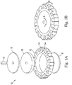
- the omni-wheel includes a hub 12 and a plurality of rollers 14 arranged around the outer periphery of the hub 12.
- the rollers are arranged perpendicular to the direction of axial rotation of the hub 12.
- the hub 12 can include spokes or other structure (e.g. a circular web of material) that extend toward the center of the hub for mounting to an axle 13.
- the rollers 14 and the rollers discussed below can be mounted to the hub 12 via pins, protrusions, axles, or other suitable structure that permits the rollers to rotate.
- the rollers can be made of a material or have a surface texture (e.g., rubber, soft plastic, or surface textured steel, etc.) or be knurled or have a surface coating so that the rollers can provide a coefficient of friction that is sufficient for the wheel to provide traction so that it can drive/steer a vehicle in a vertical and/or upside- down orientation when the weight of the vehicle counteracts the normal force provided by the magnet 16, as discussed in more detail below.
- the rollers can also be made of a magnetically inducible material and incorporate friction enhancing treatments. Thus, the force required by the magnet can be reduced, which increases the efficiency when the vehicle travels in a right-side-up orientation.
- the hub 12 permits rotation in the direction indicated by the arrow "A” about an axle 13 that defines a first axial direction.
- the rollers 14 permit rotation in the direction indicated by arrow “B” that is in a second axial direction perpendicular to the first axial direction.
- Mecanun type wheels can be used instead, in which case the rollers are mounted at 45° relative to the hub).
- the omni-wheel permits rotation with two degrees of freedom. This arrangement is particularly useful for vehicles that must operate in tight confines, such as robotic vehicles used to inspect pipes, tanks, and other metallic structures.
- a magnetic disk 16 is located within hub 12.
- the magnetic disk 16 can be mounted to the hub for free rotation with respect to the hub.
- the magnetic disk 16 provides a magnetic flux force and the material, size/number, and strength of the magnetic(s) are selected so as to hold the omni-wheel in contact with a ferrous surface material (e.g., a steel tank or pipe wall).
- ferrous disks 18 can be placed on the sides of the magnetic disk 16 in order to further direct the magnetic flux force from the magnetic disk 16 toward the ferrous surface, thereby increasing the attractive force between the disk and the surface. This arrangement results in a stronger holding force of the wheel.
- a non-magnetically inducible ring (e.g., non-magnetically inducible plastic ring) can be disposed around the magnet to protect the magnet from being exposed to the environment while avoiding flux leakage "short- circuiting" between the hub, disks, and/or traveling surface. It is also possible to use the ring to lock the rotation of the disk and/or hub forcing the magnet and disk/hub to rotate together.
- the disks 18, which can be made from steel (or other magnetically polarizable / magnetically inducible material), enclose the inner section of the hub 12, thus coupling the magnetic flux on each side of the hub 12.
- the wheel10 provides a pull force in the direction of a metallic surface on which the wheel is to move via the magnet 16 and disks 18, while simultaneously allowing two degrees of freedom of movement of the wheel along the surface via rotation of the hub 12 and the rollers 14.
- the ferrous disk 18 can be attached to the hub 12 and can include an axial mounting hole 19 for attachment to the axle 13.
- the attachment between the disk 18 and the axle 13 can be fixed such that the axle 13 can be used to drive the omni-wheel 10, such as when the omni-wheel 10 is connected to a robotic vehicle, for example.
- the disk 18 can be connected to the axle 13 via a rotational connection so that the omni-wheel can spin freely with respect to axle 13, such as when the omni-wheel 10 is a passive follower-wheel of a robot vehicle that is driven by other means, for example.
- the magnetic disk 16 can also be fixedly attached or rotationally attached to the axle 13 so that it can either rotate with the axle or rotate freely with respect to the axle, respectively.
- a magnetic ring or an array of a plurality of magnets can be located within the hub 12.
- the magnet(s) (e.g., disk, ring, array, etc.) is (are) aligned such that its (their) polarization is consistent in regard to the opposing faces of the wheel 10 as being magnetically opposite.
- the magnets can all be aligned so that all the magnets present a south pole to one face of the wheel and a north pole to the other face of the wheel.
- the magnets can be concentrically arranged about an axis of the wheel and radially spaced from the axis.
- the magnets can be high temperature magnets (e.g., magnets that can withstand high temperatures without unacceptable degradation of the magnetic field strength).
- the magnets can also be permanent magnets, electromagnets, or a combination thereof.
- the size, strength, and number of magnets can be varied in order to control the attractive force between the wheel and the surface by interchanging the magnetic disk, ring, or array for one or the other, and/or replacing the magnetic disk, ring, or array with the same structural arrangement with the disk/ring/array having a high magnetic flux, a low magnetic flux, or a desired amount appropriate for the intended operating conditions (e.g., by varying size and or materials of the magnet).
- the hub can include structure that provides cavities for mounting any one or all of these magnetic shapes, i.e., disk, ring, or array, either alone or in combination so that the magnetic flux strength and field shape can be customized for the intended application. This provides for scalability and flexibility in providing a specifically selected magnetic flux for the desired application.
- the magnetic force can be increased in certain instances in which the wheel(s) is connected to a relatively heavy robotic inspection vehicle, for example.
- the size of the wheel, its hub, rollers, and magnets can be scaled based on a variety of applications, from very small robotic vehicles to large passenger vehicles.
- a magnetic disk, ring, or array of magnets located in the hub offers significant advantages over designs in which the rollers are themselves magnetic.
- the present design reduces magnetic interference and changing fields, which lessens the attractive force to the surface and potentially damages or interferes with electronic equipment.
- the present design enables the use of two sets of rollers around the periphery of the hub 12. This arrangement is particularly useful in applications that require traversing three-dimensional structures that are made from ferrous materials, such as pipes and tanks, etc.
- the magnetic omni-wheel permits travel on vertical surfaces as well as upside-down travel since the magnet provides sufficient attractive force to maintain contact between the wheel and the surface in these orientations.
- the magnetic omni-wheel can also be used in other forms of transport, such as part of a roller system for the movement of goods in a warehouse of factory, for example.
- an omni-wheel 10a is shown that is similar to the omni- wheel 10 shown in Figs. 1A and 1B except that the ferrous disks 18a are larger in diameter.
- the ferrous disks 18a are sized such that their diameter is just smaller than the circumferential diameter of the rollers 14a arranged around the hub of the wheel. Accordingly, the ferrous disks 18a are closer to the surface over which the wheel traverses. This structural arrangement improves the direction of the magnetic flux toward the surface to increase the attractive force between the wheel and the surface.
- many of the characteristics and features of the embodiment described above can be applied to the embodiments below.
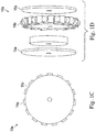
- an omni-wheel 20 that includes two sets of hubs and rollers 21, 22 are mounted together into a common unit.
- the number, size, shape, and spacing of the rollers 22 can be varied in relation to the diameter of the hub 21 so that the omni-wheel has a near-perfect circle profile.
- Such a configuration results in the wheel approximating a functionally perfectly circular rotation profile that eliminates bumps, oscillations, stall points, and drive force variations due to the shape of the wheel. Accordingly, as the hub rotates and one roller moves out of contact with the traveling surface the next roller successively is brought into contact with the surface. Thus, the surface contact points of the individual rollers together form a circle.
- This arrangement eliminates “bumps” in the travel of the wheel that otherwise can be caused by the wheel falling into "gaps” between successive rollers if they were spaced too far apart, for example.
- the diameter of the hub increases the number of rollers disposed around the hub is increased so that the rollers maintain smooth contact with the surface as the hub rotates.
- the near-perfect circle of contact means that there is a linear relationship between the degree of rotation of the wheel and the distance travelled, thus improving position control and accuracy.
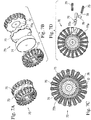
- an omni-wheel 30 with rollers 32 that have an elliptical, three-part segmented shape that also forms a near-perfect circle around the hub, and which also eliminates bumps in the travel of the wheel.
- the wheel30 can include two hubs 25, 34 on each side of the wheel.
- Each hub 34 includes mounting brackets 36 for mounting the rollers 32.
- the rollers consist of three segments 32a, 32b, and 32c that are shaped to form part of the elliptical shape.
- the rollers are mounted via a pin 37 and bearings 38 that are supported by mounting holes in the brackets.
- a spacer ring 39 can be placed between the two hubs 34 which defines a cavity between the two hubs.
- a magnet can be placed in the cavity between the two hubs.
- the "near-perfect circle” design of wheel 30 eliminates bumps that can cause oscillation of the axle, which in turn can cause oscillation of a vehicle that is attached to the axle. Such oscillation could interfere with operation of that vehicle and/or disrupt any sensors or instruments mounted on that vehicle, such as an inspection robot, for example, and are minimized by the structure of the embodiments herein.
- the near-perfect circle design eliminates stall points that could otherwise occur as an imperfect wheel can fall into the valleys between successive rollers. Once one such imperfect wheel fell into one of those valleys it would take additional torque force to rotate the wheel out of that valley and on to the next roller.
- the imperfect wheel were stopped, there would be a tendency for the wheel to continue to rotate until it was resting in one of the valleys between the rollers. This would interfere with operation of the vehicle and make it difficult to stop the vehicle at a precise location because of the natural tendency of the wheel to rotate to the next valley.
- the near-perfect circle configuration helps maintain a continuous flux so as to minimize if not eliminate these and other problems.
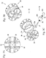
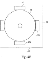
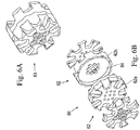
- an omni-wheel 40 includes an array of magnets 41 are located between two hubs 42, each having rollers 44.
- the magnets 41 can be mounted to a mounting assembly 46.
- the mounting assembly 46 can include structure (e.g., spokes, circular web, etc.) that extends toward the center of the assembly 46 so that the assembly can be mounted to the axle A with the assembly 46 and the magnets 41 thereon able to rotate freely with respect to the axle and with respect to the hubs and rollers 42, 44.
- the mounting assembly 46 includes carriages 47.
- a magnet 41 is inserted into each respective carriage 47 and supported thereby.
- the top portion of each carriage 47 includes connecting portions that angle toward a collar that is disposed around axle A.
- the angle of the connecting portions can be selected based on the number of magnets to be supported such that the carriages are equally spaced around the circular axle.
- the two hubs 42 can be part of a unitary structure with a cylindrical extension connecting the two hubs, in which case the assembly 46 can be sized and shaped to rotate freely about the cylindrical extension.
- carriage mounted magnets can also be used with wheels that do not include rollers.
- the magnets 41 are arranged around the assembly 46 and oriented at different angles with respect to each other.
- the angles of orientation can include 20°, 30°, 45°, 60°, 90°, 120°, or other suitable angles, for example.
- Fig. 4B illustrates the magnets mounted on mounting assembly 46 (shown here as a mounting disk) and oriented at 90° with respect to each other.
- mounting assembly 46 shown here as a mounting disk
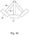
- one of the magnets 41a can be oriented toward the floor surface at a first angle and another of the magnets 4lb, which is mounted at a different angle, can be oriented toward the wall surface.
- two different magnets can simultaneously provide attractive holding force between two different surfaces.
- Such a structural arrangement enhances the ability of the omni-wheel to transition between traveling along a first surface to a second surface (e.g., floor to wall) since attractive force between the two surfaces is always maintained.
- the magnet 41 that provided the attractive force to the new surface maintains its magnetic purchase with that surface and rotates freely with respect to the omni-wheels.
- the magnet in the array that is engaged with the wall rotates from having a frontward orientation to having a downward orientation and the magnetic that had a downward orientation now has a rearward orientation.
- the magnets 41 can be mounted on independent, offset spokes 48 such that not only do the magnets rotate freely with respect to the axle and omni-wheels, but they also rotate freely with respect to each other. In this arrangement, the magnets 40 can rotate to be oriented into a position that has maximum magnetic attraction between the surfaces at a junction.
- the diameter of the mounting assembly 46 and spokes 48 is selected such that the surface of the magnets do not extend past the rollers. In this way, the magnets can be maintained close enough to the surface to provide magnetic engagement without contacting the surface and creating friction.
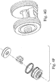
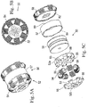
- each hub 52 includes two halves consisting of a base 52a and a cover 52b.
- the base 52a and the cover 52b each include a plurality or recesses 53 to receive rollers 54.
- the base 52a and cover 52b include holes 55 that are sized and shaped to receive the roller axle 56 when the cover 52b is connected to the base 52a. This configuration permits easy assembly of the hub 52.
- the rollers 54 With the cover 52 detached from the base 52a, the rollers 54 can be placed in their respective recesses 53. With the rollers in place, the cover 52b can be attached to the base 52a, for example, via fasteners (e.g., screws or bolts).
- the two hubs 52 can be connected together with a spacer ring 57 disposed between the two' hubs.
- the spacer ring 57 defines a cavity into which magnet 58 can be inserted.
- the size of the spacer ring 57 can be varied to accommodate larger or smaller magnets, thereby permitting adjustment of the magnetic force based on the particular application.
- the hubs 52 and the spacer ring 57 can include corresponding indexing notches 59. The indexing notches 59 ensure that each hub 52 is attached in the proper circular orientation with respect to the other hub. As can be seen in Fig.
- the hubs 52 are attached in a phase-shifted orientations such that the rollers 54 of one hub are aligned with the gaps between the rollers of the other hub. Phase-shifting the rollers helps reduces the bumps as the wheel rotates on a surface.
- an omni-wheel 60 with two-part hubs 62 is shown.
- the omni-wheel60 is similar to omni-wheel 50 in that they both include hubs that have a base and a cover for mounting rollers.
- the base 62a of each hub includes a recess 64. Each recess defines a cavity into which a magnet can be inserted.
- the hubs can have at least one threaded hole to be used to detach the magnet from the bodies during disassembly of the multidirectional wheel.
- the omni-wheel 70 that includes mounting wedges 76 is shown.
- the omni-wheel 70 includes two hubs 72, a spacer ring 73 disposed between the two hubs, wherein the spacer ring 73 defines a cavity for receiving magnet 74.
- Each hub 72 includes a plurality of rollers 75 that are attached to the hub via mounting wedges 76.
- the hub 72 includes a plurality of mounting holes 77a that correspond to a mounting hole 77b on each wedge 76 so that the wedges can be connected to the hub (e.g., via a fastener such as a screw, bolt, rivet, pin, etc.).
- Each wedge includes an axle mounting hole 78 that is sized and shaped to receive axle 79.
- rollers 75 are mounted on axle 79 which is supported in the axle mounting hole 78 of wedge 76.
- the wedge 76 is attached to the hub 72 via mounting holes 77a and 77b.
- the wheel can be readily assembled and dissembled.
- the wedges 76 can be made of magnetically inducible material (e.g., ferrous material) that acts as a flux concentrator.
- the size and shape of the wedges can be varied such that the distance D between edge of the wedge and the surface is reduced which results in an increase of the magnetic attractive force between the wheel and the surface.
- the distance D can be minimized up to the boundary defined by the rollers as the rollers rotate into contact with the surface.
- This contact boundary is circular in nature and, as described above, is defined by the surface contact points of the individual rollers together. It is desirable to size and shape the hubs or the parts thereof (e.g., the wedges) so that the hubs extend up to the circular boundary without crossing it. Crossing the circular boundary can create a frictioned contact between the hub and surface and interfere with the rolling of the rollers.
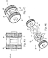
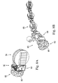
- the drive system 80 includes a magnetic omni-wheel 82 and a driving wheel84.
- the magnetic omni- wheel 82 is attached to the chassis of drive system 80 and is oriented along a first axial direction.
- the driving wheel 84 is attached to the chassis 85 of drive system 80 and is oriented along a second axial direction that is perpendicular to the first.
- the drive wheel 84 can be driven (e.g., via a motor and gear assembly) to provide forward and reverse locomotion of the drive system 80.
- the omni-wheel82 is perpendicular to the drive wheel 84, the rollers 86 on the omni-wheel are aligned with the drive wheel 84 and, therefore, the drive system 80 can traverse a surface with relatively little friction introduced by the omni-wheel itself.
- the omni-wheel can also be driven (e.g., via a motor and gear assembly) so as to cause the omni-wheel to rotate which causes the drive system 80 to pivot since the omni-wheel 82 is mounted perpendicular to the drive wheel84.
- a vehicle can be driven and steered in a simple manner by controlling the rotation of the drive wheel 84 and the omni-wheel 82, respectively.
- the omni-wheel 82 can be any one of the omni-wheel configurations described herein.
- Fig. 8B illustrates a chained device in which a drive system 80 that includes both an omni-wheel 82 and drive wheel84 is linked with additional drive systems 88 that only include drive wheels.
- a drive system 80 that includes both an omni-wheel 82 and drive wheel84 is linked with additional drive systems 88 that only include drive wheels.
Landscapes
- Engineering & Computer Science (AREA)
- Mechanical Engineering (AREA)
- Rolling Contact Bearings (AREA)
- Arrangement Or Mounting Of Propulsion Units For Vehicles (AREA)
- Rolls And Other Rotary Bodies (AREA)
- Motorcycle And Bicycle Frame (AREA)
- Dynamo-Electric Clutches, Dynamo-Electric Brakes (AREA)
- Rollers For Roller Conveyors For Transfer (AREA)
Applications Claiming Priority (3)
| Application Number | Priority Date | Filing Date | Title |
|---|---|---|---|
| US201361910320P | 2013-11-30 | 2013-11-30 | |
| EP14816506.1A EP3074241B1 (en) | 2013-11-30 | 2014-11-24 | Magnetic omni-wheel |
| PCT/US2014/067152 WO2015081020A1 (en) | 2013-11-30 | 2014-11-24 | Magnetic omni-wheel |
Related Parent Applications (1)
| Application Number | Title | Priority Date | Filing Date |
|---|---|---|---|
| EP14816506.1A Division EP3074241B1 (en) | 2013-11-30 | 2014-11-24 | Magnetic omni-wheel |
Publications (1)
| Publication Number | Publication Date |
|---|---|
| EP3693183A1 true EP3693183A1 (en) | 2020-08-12 |
Family
ID=52144877
Family Applications (2)
| Application Number | Title | Priority Date | Filing Date |
|---|---|---|---|
| EP14816506.1A Active EP3074241B1 (en) | 2013-11-30 | 2014-11-24 | Magnetic omni-wheel |
| EP20163441.7A Withdrawn EP3693183A1 (en) | 2013-11-30 | 2014-11-24 | Magnetic omni-wheel |
Family Applications Before (1)
| Application Number | Title | Priority Date | Filing Date |
|---|---|---|---|
| EP14816506.1A Active EP3074241B1 (en) | 2013-11-30 | 2014-11-24 | Magnetic omni-wheel |
Country Status (9)
| Country | Link |
|---|---|
| US (3) | US9579927B2 (es) |
| EP (2) | EP3074241B1 (es) |
| JP (1) | JP6465887B2 (es) |
| KR (2) | KR102330848B1 (es) |
| CN (2) | CN106061754B (es) |
| ES (1) | ES2788379T3 (es) |
| SA (1) | SA516371224B1 (es) |
| SG (3) | SG11201604612QA (es) |
| WO (1) | WO2015081020A1 (es) |
Families Citing this family (39)
| Publication number | Priority date | Publication date | Assignee | Title |
|---|---|---|---|---|
| US11093722B2 (en) | 2011-12-05 | 2021-08-17 | Adasa Inc. | Holonomic RFID reader |
| US10846497B2 (en) | 2011-12-05 | 2020-11-24 | Adasa Inc. | Holonomic RFID reader |
| CA2813399C (en) * | 2013-04-09 | 2020-03-24 | William Liddiard | Omnidirectional wheel |
| EP3770049B1 (en) | 2013-11-30 | 2022-03-02 | Saudi Arabian Oil Company | Robotic vehicle chassis |
| CN105992900B (zh) * | 2013-11-30 | 2018-03-20 | 沙特阿拉伯石油公司 | 用于计算装置的取向的系统和方法 |
| EP3034324A1 (de) * | 2014-12-16 | 2016-06-22 | Omniroll AG | Mecanumradfahrzeug |
| KR101548609B1 (ko) * | 2014-12-23 | 2015-09-01 | 주식회사 타스글로벌 | 자석휠 |
| EP3242803B1 (en) * | 2015-01-06 | 2023-06-07 | Rotacaster Wheel Pty Ltd | Wheel frame component |
| CN105584290B (zh) * | 2016-01-15 | 2018-03-13 | 京东方科技集团股份有限公司 | 全向轮、运动装置和运动装置的控制方法 |
| WO2017136290A1 (en) | 2016-02-02 | 2017-08-10 | Deka Products Limited Partnership | Modular electro-mechanical agent |
| US10518576B1 (en) * | 2016-03-03 | 2019-12-31 | Al Incorporated | Expandable wheel |
| US10214050B1 (en) | 2016-03-03 | 2019-02-26 | Al Incorporated | Robotic floor cleaning device with expandable wheels |
| US11829148B1 (en) | 2016-03-03 | 2023-11-28 | AI Incorporated | Cleaning robot and operation thereof |
| US10239347B2 (en) * | 2016-05-18 | 2019-03-26 | Saudi Arabian Oil Company | Magnetic omni-wheel with roller bracket |
| CN106004230B (zh) * | 2016-05-30 | 2018-05-25 | 哈工大机器人集团有限公司 | 一种可爬越凹凸面的柔性磁铁轮 |
| JP6715462B2 (ja) * | 2016-06-02 | 2020-07-01 | パナソニックIpマネジメント株式会社 | 移動ロボット |
| CN109195809B (zh) * | 2016-06-07 | 2022-02-01 | 国立大学法人东北大学 | 全向旋转驱动机构及移动体 |
| USD824971S1 (en) | 2016-07-27 | 2018-08-07 | Deka Products Limited Partnership | Gear |
| US10766501B2 (en) * | 2016-12-02 | 2020-09-08 | Tong Li | Magnetic elevated wheel |
| EP3974823B1 (en) | 2016-12-23 | 2024-03-06 | Gecko Robotics, Inc. | Inspection robot |
| CN106515942B (zh) * | 2016-12-23 | 2022-01-07 | 桂林电子科技大学 | 可全方位运动的独轮车机构 |
| US11307063B2 (en) | 2016-12-23 | 2022-04-19 | Gtc Law Group Pc & Affiliates | Inspection robot for horizontal tube inspection having vertically positionable sensor carriage |
| USD829627S1 (en) | 2017-01-30 | 2018-10-02 | Deka Products Limited Partnership | Wheel |
| US10451222B2 (en) | 2017-07-12 | 2019-10-22 | Saudi Arabian Oil Company | Magnetic crawler vehicle with passive rear-facing apparatus |
| CN107719015A (zh) * | 2017-11-17 | 2018-02-23 | 南昌大学 | 一种机电一体式新型全向结构轮装置 |
| US11577794B2 (en) | 2017-11-22 | 2023-02-14 | Sector Industries, Inc. | Apparatus and related method for coating an irregular surface |
| US11312435B2 (en) * | 2018-07-18 | 2022-04-26 | General Electric Company | Motorized apparatus including articulated body |
| CN108894482A (zh) * | 2018-07-19 | 2018-11-27 | 浙江升浙建设集团有限公司 | 一种新型施工用脚手架 |
| JP7037184B2 (ja) * | 2018-10-12 | 2022-03-16 | 白山工業株式会社 | 全方向車輪及び全方向車輪を用いた全方向移動車両と地震動シミュレータを含む加振装置並びにこれらの使用方法 |
| US20220072698A1 (en) * | 2018-11-05 | 2022-03-10 | Magswitch Technology Worldwide Pty Lt. | Magnetic base for robotic arm |
| US11097796B2 (en) * | 2018-11-29 | 2021-08-24 | Saudi Arabian Oil Company | Articulated magnet-bearing legs for UAV landing on curved surfaces |
| MX2021007801A (es) * | 2018-12-28 | 2021-10-13 | Petroleo Brasileiro Sa Petrobras | Ruedas mecanum aplicadas al sistema para mover una plataforma movil suspendida en superficies planas verticales y horizontales. |
| EP3934861A4 (en) | 2019-03-08 | 2022-12-07 | Gecko Robotics, Inc. | INSPECTION ROBOT |
| US11267283B2 (en) | 2019-04-05 | 2022-03-08 | Honda Motor Co., Ltd. | Omni-direction wheel system and methods for controlling the omni-direction wheel system |
| CN110015350B (zh) * | 2019-04-19 | 2020-11-17 | 武汉理工大学 | 金属壁面自适应攀爬机器人 |
| CN110155202A (zh) * | 2019-06-03 | 2019-08-23 | 洛阳圣瑞智能机器人有限公司 | 一种过渡面爬壁磁吸附机器人的行走底盘装置 |
| USD928680S1 (en) * | 2019-12-27 | 2021-08-24 | Rotacaster Wheel Pty Ltd. | Multiple directional wheel rim |
| CA3173116A1 (en) | 2021-04-20 | 2022-10-20 | Edward A. Bryner | Flexible inspection robot |
| US11971389B2 (en) | 2021-04-22 | 2024-04-30 | Gecko Robotics, Inc. | Systems, methods, and apparatus for ultra-sonic inspection of a surface |
Citations (6)
| Publication number | Priority date | Publication date | Assignee | Title |
|---|---|---|---|---|
| US3590970A (en) * | 1968-12-09 | 1971-07-06 | Kornylac Co | Conveyor roller |
| JP2007022342A (ja) * | 2005-07-15 | 2007-02-01 | Soai:Kk | オムニホイル及び全方向移動装置 |
| US7233221B2 (en) | 2003-02-19 | 2007-06-19 | Applus Norcontrol, S.L. (Sociedad Unipersonal) | Magnetic wheel for vehicles |
| US20080295595A1 (en) | 2007-05-31 | 2008-12-04 | Twill Tech, Inc. | Dynamically balanced in-line wheel vehicle |
| US20120200380A1 (en) | 2006-03-13 | 2012-08-09 | Magswitch Technology Worldwide Pty Ltd | Magnetic wheel |
| US8308604B2 (en) | 2008-12-26 | 2012-11-13 | Chung Hua University | Omni-wheel based driving device with belt transmission mechanism |
Family Cites Families (63)
| Publication number | Priority date | Publication date | Assignee | Title |
|---|---|---|---|---|
| US1305535A (en) | 1919-06-03 | Vehicle-wheei | ||
| US2694164A (en) * | 1952-02-07 | 1954-11-09 | Walter A Geppelt | Magnetic wheel |
| US3295700A (en) | 1963-03-08 | 1967-01-03 | Siemens Ag | Method and apparatus for handling radioactive materials |
| US3363735A (en) | 1966-03-16 | 1968-01-16 | Lockheed Aircraft Corp | Roller |
| FR1528040A (fr) | 1967-04-27 | 1968-06-07 | Poclain Sa | Véhicule à organe directeur spécial |
| YU35048B (en) | 1971-05-13 | 1980-06-30 | Snam Progetti | Self-propelled and self-adjustable carriage capable of moving along the track of a non-linear line, e.g.pipeline |
| US3789947A (en) * | 1972-04-17 | 1974-02-05 | Nasa | Omnidirectional wheel |
| US3882885A (en) | 1973-07-25 | 1975-05-13 | Continental Oil Co | Method of handling a large diameter slurry hose system |
| US4223753A (en) | 1977-12-19 | 1980-09-23 | Bradbury Harold M | Omni-directional transport device |
| US4237990A (en) | 1979-01-02 | 1980-12-09 | Hau T | Omnidirectional vehicle |
| US4335899A (en) | 1979-05-18 | 1982-06-22 | Hiscock Roger F | Wheel for toy vehicle |
| US4823900A (en) | 1984-05-01 | 1989-04-25 | Jeffrey Farnam | Four-wheel drive wheel-chair with compound wheels |
| NO851590L (no) | 1984-05-14 | 1985-11-15 | Kraftwerk Union Ag | Selvdrevet inspeksjons- og tilsynskjoeretoey. |
| JPH0162101U (es) * | 1987-10-15 | 1989-04-20 | ||
| JP2502349B2 (ja) | 1988-10-28 | 1996-05-29 | 大阪瓦斯 株式会社 | 管内走行台車 |
| US4981203A (en) | 1989-02-03 | 1991-01-01 | Kornylak Corporation | Multi directional conveyor wheel |
| KR940009860B1 (ko) | 1989-12-08 | 1994-10-18 | 가부시끼가이샤 히다찌세이사꾸쇼 | 자주식 수송기구 |
| US5284096A (en) | 1991-08-06 | 1994-02-08 | Osaka Gas Company, Limited | Vehicle for use in pipes |
| CA2093520A1 (en) | 1991-08-08 | 1993-02-09 | Akira Homma | Wheel provided with sub-wheels |
| US5323867A (en) | 1992-03-06 | 1994-06-28 | Eric J. Allard | Robot transport platform with multi-directional wheels |
| JPH05286466A (ja) * | 1992-04-07 | 1993-11-02 | Ishikawajima Inspection & Instrumentation Co | 磁石車輪 |
| US5246238A (en) | 1992-06-30 | 1993-09-21 | Brown Nathaniel R | Roller skate wheel |
| JPH07251603A (ja) * | 1994-03-16 | 1995-10-03 | Osaka Gas Co Ltd | 磁気吸着車輪 |
| US5404984A (en) | 1994-07-15 | 1995-04-11 | Hagman; Erland L. | Multi-directional roller |
| US5551349A (en) | 1995-06-29 | 1996-09-03 | The United States Of America As Represented By The Secretary Of The Navy | Internal conduit vehicle |
| JPH09267604A (ja) * | 1996-04-02 | 1997-10-14 | Jishaku Yuso Syst Kaihatsu Kk | 磁石車輪 |
| US6125955A (en) * | 1999-03-11 | 2000-10-03 | Aqua Dynamics, Inc. | Magnetic wheel |
| AUPQ446699A0 (en) * | 1999-12-06 | 2000-01-06 | Kocijan, Franz | Switchable (variable) permanent magnet device |
| US7566102B2 (en) | 2000-09-21 | 2009-07-28 | Innowheel Pty Ltd. | Multiple roller wheel |
| US6672413B2 (en) * | 2000-11-28 | 2004-01-06 | Siemens Westinghouse Power Corporation | Remote controlled inspection vehicle utilizing magnetic adhesion to traverse nonhorizontal, nonflat, ferromagnetic surfaces |
| JP2003063202A (ja) | 2001-08-24 | 2003-03-05 | Kyosho Corp | 走行体の車輪 |
| AU2002356817A1 (en) | 2001-10-17 | 2003-04-28 | William Marsh Rice University | Autonomous robotic crawler for in-pipe inspection |
| US7182025B2 (en) | 2001-10-17 | 2007-02-27 | William Marsh Rice University | Autonomous robotic crawler for in-pipe inspection |
| KR100520272B1 (ko) | 2002-02-15 | 2005-10-11 | 주식회사 비에스텍 | 전방향 이동 승용완구 |
| CN1702008A (zh) * | 2005-06-14 | 2005-11-30 | 胡广怀 | 磁吸附式爬壁机器用引磁式行走轮单元 |
| US7520356B2 (en) | 2006-04-07 | 2009-04-21 | Research Foundation Of The City University Of New York | Modular wall climbing robot with transition capability |
| US7730978B2 (en) | 2006-06-30 | 2010-06-08 | Donald Dixon | All-terrain robotic omni-directional drive assembly |
| ES2334186B1 (es) | 2006-08-11 | 2010-12-28 | Ventol España S.L. | Robot trepador limpiador. |
| US7949437B2 (en) | 2007-03-12 | 2011-05-24 | Tamkang University | Omnidirectional movement control system |
| ITBS20070154A1 (it) | 2007-10-11 | 2009-04-12 | Tecnomac Srl | Robot mobile ad ancoraggio magnetico |
| KR101075578B1 (ko) * | 2007-11-20 | 2011-10-20 | 대지종건(주) | 자기력을 이용한 강구조물 표면 이동 장치 |
| NO328066B1 (no) * | 2008-01-25 | 2009-11-23 | Helix Technologies As | Rortraktor |
| KR101380269B1 (ko) * | 2008-08-22 | 2014-04-01 | 무라다기카이가부시끼가이샤 | 자율 이동 장치 |
| US8342281B2 (en) | 2008-11-21 | 2013-01-01 | Raytheon Company | Hull robot steering system |
| WO2010064408A1 (ja) * | 2008-12-05 | 2010-06-10 | 本田技研工業株式会社 | 車輪及びそれを用いた摩擦式駆動装置及び全方向移動体 |
| US7980335B2 (en) | 2009-01-26 | 2011-07-19 | Foster-Miller, Inc. | Omni-directional wheel |
| KR20100120324A (ko) * | 2009-05-06 | 2010-11-16 | (주)로멕스테크놀로지 | 자석이 형성된 바퀴 |
| US8393421B2 (en) | 2009-10-14 | 2013-03-12 | Raytheon Company | Hull robot drive system |
| KR101012719B1 (ko) * | 2010-01-15 | 2011-02-09 | (주)엔티렉스 | 메카넘 전동 휠체어 |
| US8269447B2 (en) | 2010-03-17 | 2012-09-18 | Disney Enterprises, Inc. | Magnetic spherical balancing robot drive |
| CH702955A1 (de) | 2010-04-14 | 2011-10-14 | Alstom Technology Ltd | Antriebseinheit für ein in rohrsystemen, hohlräumen oder dergleichen nach art eines roboters einsetzbares fahrzeug sowie fahrzeug mit einer solchen antriebseinheit. |
| US20110272998A1 (en) * | 2010-05-10 | 2011-11-10 | Tsongli Lee | Omni-directional transport device |
| JP2012030735A (ja) * | 2010-08-02 | 2012-02-16 | Panasonic Corp | 全方向車輪および移動装置 |
| US8879639B2 (en) * | 2011-01-31 | 2014-11-04 | Hand Held Products, Inc. | Adaptive video capture decode system |
| CN202115264U (zh) * | 2011-04-22 | 2012-01-18 | 成都航发液压工程有限公司 | 一种全向轮 |
| CN202011305U (zh) * | 2011-04-22 | 2011-10-19 | 成都航发液压工程有限公司 | 一种新型全向轮 |
| DE102011053903A1 (de) * | 2011-09-23 | 2013-03-28 | Zdenek Spindler | Mecanumrad sowie Mecanumradfahrzeug |
| JP5687174B2 (ja) | 2011-11-24 | 2015-03-18 | 本田技研工業株式会社 | 全方向移動装置用の走行車輪、摩擦式駆動装置および全方向移動装置 |
| US8960339B2 (en) * | 2012-05-03 | 2015-02-24 | Helical Robotics, Llc | Mecanum wheel |
| CN202622792U (zh) * | 2012-06-07 | 2012-12-26 | 中国东方电气集团有限公司 | 一种新型的差动驱动复合吸附式爬壁机器人 |
| CN102689296B (zh) * | 2012-06-07 | 2015-02-11 | 中国东方电气集团有限公司 | 一种新型的差动驱动复合吸附式爬壁机器人 |
| CN104797485A (zh) | 2012-11-15 | 2015-07-22 | 株式会社海博特 | 管内行走装置和行走体 |
| US20140152803A1 (en) * | 2012-11-16 | 2014-06-05 | Northeast Gas Association | System, method & apparatus for remote pipe inspection |
-
2014
- 2014-11-24 WO PCT/US2014/067152 patent/WO2015081020A1/en active Application Filing
- 2014-11-24 EP EP14816506.1A patent/EP3074241B1/en active Active
- 2014-11-24 SG SG11201604612QA patent/SG11201604612QA/en unknown
- 2014-11-24 US US14/552,010 patent/US9579927B2/en active Active
- 2014-11-24 SG SG10201901776VA patent/SG10201901776VA/en unknown
- 2014-11-24 KR KR1020167016801A patent/KR102330848B1/ko active IP Right Grant
- 2014-11-24 JP JP2016535171A patent/JP6465887B2/ja not_active Expired - Fee Related
- 2014-11-24 CN CN201480072184.0A patent/CN106061754B/zh not_active Expired - Fee Related
- 2014-11-24 CN CN201811066352.1A patent/CN109249751A/zh active Pending
- 2014-11-24 SG SG10201807619WA patent/SG10201807619WA/en unknown
- 2014-11-24 KR KR1020217037733A patent/KR20210142778A/ko not_active Application Discontinuation
- 2014-11-24 ES ES14816506T patent/ES2788379T3/es active Active
- 2014-11-24 EP EP20163441.7A patent/EP3693183A1/en not_active Withdrawn
-
2016
- 2016-05-29 SA SA516371224A patent/SA516371224B1/ar unknown
-
2017
- 2017-02-17 US US15/436,368 patent/US9849722B2/en active Active
- 2017-07-05 US US15/642,050 patent/US10532609B2/en active Active
Patent Citations (6)
| Publication number | Priority date | Publication date | Assignee | Title |
|---|---|---|---|---|
| US3590970A (en) * | 1968-12-09 | 1971-07-06 | Kornylac Co | Conveyor roller |
| US7233221B2 (en) | 2003-02-19 | 2007-06-19 | Applus Norcontrol, S.L. (Sociedad Unipersonal) | Magnetic wheel for vehicles |
| JP2007022342A (ja) * | 2005-07-15 | 2007-02-01 | Soai:Kk | オムニホイル及び全方向移動装置 |
| US20120200380A1 (en) | 2006-03-13 | 2012-08-09 | Magswitch Technology Worldwide Pty Ltd | Magnetic wheel |
| US20080295595A1 (en) | 2007-05-31 | 2008-12-04 | Twill Tech, Inc. | Dynamically balanced in-line wheel vehicle |
| US8308604B2 (en) | 2008-12-26 | 2012-11-13 | Chung Hua University | Omni-wheel based driving device with belt transmission mechanism |
Also Published As
| Publication number | Publication date |
|---|---|
| SG11201604612QA (en) | 2016-07-28 |
| JP6465887B2 (ja) | 2019-02-06 |
| SA516371224B1 (ar) | 2020-08-05 |
| CN109249751A (zh) | 2019-01-22 |
| SG10201901776VA (en) | 2019-03-28 |
| US20170166004A1 (en) | 2017-06-15 |
| US20150151572A1 (en) | 2015-06-04 |
| KR20160103992A (ko) | 2016-09-02 |
| SG10201807619WA (en) | 2018-10-30 |
| EP3074241B1 (en) | 2020-04-01 |
| CN106061754A (zh) | 2016-10-26 |
| US20170297366A1 (en) | 2017-10-19 |
| US9849722B2 (en) | 2017-12-26 |
| ES2788379T3 (es) | 2020-10-21 |
| JP2017502869A (ja) | 2017-01-26 |
| EP3074241A1 (en) | 2016-10-05 |
| KR20210142778A (ko) | 2021-11-25 |
| US9579927B2 (en) | 2017-02-28 |
| CN106061754B (zh) | 2018-10-09 |
| US10532609B2 (en) | 2020-01-14 |
| KR102330848B1 (ko) | 2021-11-25 |
| WO2015081020A1 (en) | 2015-06-04 |
Similar Documents
| Publication | Publication Date | Title |
|---|---|---|
| US10532609B2 (en) | Method for traversing surface with magnetic omni-wheel | |
| EP1832445B1 (en) | Universal transmission roller wheel | |
| CN102673673A (zh) | 一种用于磁吸附爬壁机器人的新型万向滚动磁轮装置 | |
| US10119592B2 (en) | Vehicle drivetrain with active magnetic bearings | |
| EP1595720A1 (en) | Magnetic wheel for vehicles | |
| WO2006133627A1 (fr) | Unite roue de marche magnetisante pour dispositif d'escalade en milieu artificiel a adsorption magnetique | |
| CN109070628B (zh) | 具有滚轮支架的磁性全向轮 | |
| CN203681134U (zh) | 一体化磁吸附麦克纳姆轮 | |
| CN202686558U (zh) | 一种用于磁吸附爬壁机器人的磁吸附万向轮装置 | |
| CN202686556U (zh) | 一种用于磁吸附爬壁机器人的新型万向滚动磁轮装置 | |
| US6356000B1 (en) | Magnetically augmented rotation system | |
| US20140203678A1 (en) | Magnetic coupling | |
| CN203844532U (zh) | 一种易装配、大承载的全方位移动轮 | |
| KR102277252B1 (ko) | 자체감속 기능을 갖는 메카넘 휠 | |
| US10377231B2 (en) | Magnet-assisted ball drive | |
| CN110217044A (zh) | 多极取向磁力轮及其安装方法 | |
| CN106208616A (zh) | 永磁齿轮 | |
| KR101328880B1 (ko) | 길게 연장된 전도성 소재의 이송을 위한 자기차륜 조립체 및 이를 갖는 장치 | |
| JPH06229451A (ja) | 磁石式ボール遊星減速装置 |
Legal Events
| Date | Code | Title | Description |
|---|---|---|---|
| PUAI | Public reference made under article 153(3) epc to a published international application that has entered the european phase |
Free format text: ORIGINAL CODE: 0009012 |
|
| STAA | Information on the status of an ep patent application or granted ep patent |
Free format text: STATUS: THE APPLICATION HAS BEEN PUBLISHED |
|
| AC | Divisional application: reference to earlier application |
Ref document number: 3074241 Country of ref document: EP Kind code of ref document: P |
|
| AK | Designated contracting states |
Kind code of ref document: A1 Designated state(s): AL AT BE BG CH CY CZ DE DK EE ES FI FR GB GR HR HU IE IS IT LI LT LU LV MC MK MT NL NO PL PT RO RS SE SI SK SM TR |
|
| STAA | Information on the status of an ep patent application or granted ep patent |
Free format text: STATUS: REQUEST FOR EXAMINATION WAS MADE |
|
| 17P | Request for examination filed |
Effective date: 20201203 |
|
| RBV | Designated contracting states (corrected) |
Designated state(s): AL AT BE BG CH CY CZ DE DK EE ES FI FR GB GR HR HU IE IS IT LI LT LU LV MC MK MT NL NO PL PT RO RS SE SI SK SM TR |
|
| STAA | Information on the status of an ep patent application or granted ep patent |
Free format text: STATUS: THE APPLICATION HAS BEEN WITHDRAWN |
|
| 18W | Application withdrawn |
Effective date: 20220128 |