EP3686417B1 - Dispositif et procédé de commande de quantité d'injection d'injecteur, programme et support d'informations - Google Patents
Dispositif et procédé de commande de quantité d'injection d'injecteur, programme et support d'informations Download PDFInfo
- Publication number
- EP3686417B1 EP3686417B1 EP17926001.3A EP17926001A EP3686417B1 EP 3686417 B1 EP3686417 B1 EP 3686417B1 EP 17926001 A EP17926001 A EP 17926001A EP 3686417 B1 EP3686417 B1 EP 3686417B1
- Authority
- EP
- European Patent Office
- Prior art keywords
- crank
- crank angle
- engine
- section
- torque
- Prior art date
- Legal status (The legal status is an assumption and is not a legal conclusion. Google has not performed a legal analysis and makes no representation as to the accuracy of the status listed.)
- Active
Links
- 238000002347 injection Methods 0.000 title claims description 210
- 239000007924 injection Substances 0.000 title claims description 210
- 238000000034 method Methods 0.000 title claims description 59
- 238000012937 correction Methods 0.000 claims description 97
- 239000000446 fuel Substances 0.000 claims description 50
- 239000013618 particulate matter Substances 0.000 claims description 24
- 230000005484 gravity Effects 0.000 claims description 9
- 238000013459 approach Methods 0.000 claims description 4
- 238000012545 processing Methods 0.000 description 18
- 230000006870 function Effects 0.000 description 16
- 239000011159 matrix material Substances 0.000 description 16
- 238000002485 combustion reaction Methods 0.000 description 15
- 238000010586 diagram Methods 0.000 description 14
- 230000008929 regeneration Effects 0.000 description 14
- 238000011069 regeneration method Methods 0.000 description 14
- 238000012886 linear function Methods 0.000 description 7
- BHMLFPOTZYRDKA-IRXDYDNUSA-N (2s)-2-[(s)-(2-iodophenoxy)-phenylmethyl]morpholine Chemical compound IC1=CC=CC=C1O[C@@H](C=1C=CC=CC=1)[C@H]1OCCNC1 BHMLFPOTZYRDKA-IRXDYDNUSA-N 0.000 description 5
- 230000015556 catabolic process Effects 0.000 description 5
- 238000006731 degradation reaction Methods 0.000 description 5
- 238000012360 testing method Methods 0.000 description 5
- 238000011156 evaluation Methods 0.000 description 4
- 230000000694 effects Effects 0.000 description 3
- 238000001514 detection method Methods 0.000 description 2
- 238000009434 installation Methods 0.000 description 2
- 239000004065 semiconductor Substances 0.000 description 2
- 101000802640 Homo sapiens Lactosylceramide 4-alpha-galactosyltransferase Proteins 0.000 description 1
- 102100035838 Lactosylceramide 4-alpha-galactosyltransferase Human genes 0.000 description 1
- 239000003054 catalyst Substances 0.000 description 1
- 230000006835 compression Effects 0.000 description 1
- 238000007906 compression Methods 0.000 description 1
- 230000001419 dependent effect Effects 0.000 description 1
- 238000012423 maintenance Methods 0.000 description 1
- 230000003647 oxidation Effects 0.000 description 1
- 238000007254 oxidation reaction Methods 0.000 description 1
- 239000007787 solid Substances 0.000 description 1
- 239000000243 solution Substances 0.000 description 1
- 238000006467 substitution reaction Methods 0.000 description 1
Images


Classifications
-
- F—MECHANICAL ENGINEERING; LIGHTING; HEATING; WEAPONS; BLASTING
- F02—COMBUSTION ENGINES; HOT-GAS OR COMBUSTION-PRODUCT ENGINE PLANTS
- F02D—CONTROLLING COMBUSTION ENGINES
- F02D41/00—Electrical control of supply of combustible mixture or its constituents
- F02D41/02—Circuit arrangements for generating control signals
- F02D41/14—Introducing closed-loop corrections
- F02D41/1401—Introducing closed-loop corrections characterised by the control or regulation method
-
- F—MECHANICAL ENGINEERING; LIGHTING; HEATING; WEAPONS; BLASTING
- F02—COMBUSTION ENGINES; HOT-GAS OR COMBUSTION-PRODUCT ENGINE PLANTS
- F02D—CONTROLLING COMBUSTION ENGINES
- F02D41/00—Electrical control of supply of combustible mixture or its constituents
- F02D41/02—Circuit arrangements for generating control signals
- F02D41/04—Introducing corrections for particular operating conditions
-
- F—MECHANICAL ENGINEERING; LIGHTING; HEATING; WEAPONS; BLASTING
- F02—COMBUSTION ENGINES; HOT-GAS OR COMBUSTION-PRODUCT ENGINE PLANTS
- F02D—CONTROLLING COMBUSTION ENGINES
- F02D41/00—Electrical control of supply of combustible mixture or its constituents
- F02D41/008—Controlling each cylinder individually
- F02D41/0085—Balancing of cylinder outputs, e.g. speed, torque or air-fuel ratio
-
- F—MECHANICAL ENGINEERING; LIGHTING; HEATING; WEAPONS; BLASTING
- F02—COMBUSTION ENGINES; HOT-GAS OR COMBUSTION-PRODUCT ENGINE PLANTS
- F02D—CONTROLLING COMBUSTION ENGINES
- F02D41/00—Electrical control of supply of combustible mixture or its constituents
- F02D41/02—Circuit arrangements for generating control signals
- F02D41/14—Introducing closed-loop corrections
- F02D41/1497—With detection of the mechanical response of the engine
-
- F—MECHANICAL ENGINEERING; LIGHTING; HEATING; WEAPONS; BLASTING
- F02—COMBUSTION ENGINES; HOT-GAS OR COMBUSTION-PRODUCT ENGINE PLANTS
- F02D—CONTROLLING COMBUSTION ENGINES
- F02D41/00—Electrical control of supply of combustible mixture or its constituents
- F02D41/30—Controlling fuel injection
- F02D41/32—Controlling fuel injection of the low pressure type
- F02D41/34—Controlling fuel injection of the low pressure type with means for controlling injection timing or duration
-
- F—MECHANICAL ENGINEERING; LIGHTING; HEATING; WEAPONS; BLASTING
- F02—COMBUSTION ENGINES; HOT-GAS OR COMBUSTION-PRODUCT ENGINE PLANTS
- F02D—CONTROLLING COMBUSTION ENGINES
- F02D41/00—Electrical control of supply of combustible mixture or its constituents
- F02D41/30—Controlling fuel injection
- F02D41/38—Controlling fuel injection of the high pressure type
- F02D41/40—Controlling fuel injection of the high pressure type with means for controlling injection timing or duration
-
- F—MECHANICAL ENGINEERING; LIGHTING; HEATING; WEAPONS; BLASTING
- F02—COMBUSTION ENGINES; HOT-GAS OR COMBUSTION-PRODUCT ENGINE PLANTS
- F02D—CONTROLLING COMBUSTION ENGINES
- F02D45/00—Electrical control not provided for in groups F02D41/00 - F02D43/00
-
- F—MECHANICAL ENGINEERING; LIGHTING; HEATING; WEAPONS; BLASTING
- F02—COMBUSTION ENGINES; HOT-GAS OR COMBUSTION-PRODUCT ENGINE PLANTS
- F02D—CONTROLLING COMBUSTION ENGINES
- F02D41/00—Electrical control of supply of combustible mixture or its constituents
- F02D41/02—Circuit arrangements for generating control signals
- F02D41/14—Introducing closed-loop corrections
- F02D41/1401—Introducing closed-loop corrections characterised by the control or regulation method
- F02D2041/1413—Controller structures or design
- F02D2041/1415—Controller structures or design using a state feedback or a state space representation
- F02D2041/1417—Kalman filter
-
- F—MECHANICAL ENGINEERING; LIGHTING; HEATING; WEAPONS; BLASTING
- F02—COMBUSTION ENGINES; HOT-GAS OR COMBUSTION-PRODUCT ENGINE PLANTS
- F02D—CONTROLLING COMBUSTION ENGINES
- F02D41/00—Electrical control of supply of combustible mixture or its constituents
- F02D41/30—Controlling fuel injection
- F02D41/38—Controlling fuel injection of the high pressure type
- F02D2041/389—Controlling fuel injection of the high pressure type for injecting directly into the cylinder
-
- F—MECHANICAL ENGINEERING; LIGHTING; HEATING; WEAPONS; BLASTING
- F02—COMBUSTION ENGINES; HOT-GAS OR COMBUSTION-PRODUCT ENGINE PLANTS
- F02D—CONTROLLING COMBUSTION ENGINES
- F02D2200/00—Input parameters for engine control
- F02D2200/02—Input parameters for engine control the parameters being related to the engine
- F02D2200/08—Exhaust gas treatment apparatus parameters
- F02D2200/0812—Particle filter loading
-
- F—MECHANICAL ENGINEERING; LIGHTING; HEATING; WEAPONS; BLASTING
- F02—COMBUSTION ENGINES; HOT-GAS OR COMBUSTION-PRODUCT ENGINE PLANTS
- F02D—CONTROLLING COMBUSTION ENGINES
- F02D2200/00—Input parameters for engine control
- F02D2200/02—Input parameters for engine control the parameters being related to the engine
- F02D2200/10—Parameters related to the engine output, e.g. engine torque or engine speed
- F02D2200/101—Engine speed
-
- F—MECHANICAL ENGINEERING; LIGHTING; HEATING; WEAPONS; BLASTING
- F02—COMBUSTION ENGINES; HOT-GAS OR COMBUSTION-PRODUCT ENGINE PLANTS
- F02D—CONTROLLING COMBUSTION ENGINES
- F02D41/00—Electrical control of supply of combustible mixture or its constituents
- F02D41/02—Circuit arrangements for generating control signals
- F02D41/18—Circuit arrangements for generating control signals by measuring intake air flow
- F02D41/182—Circuit arrangements for generating control signals by measuring intake air flow for the control of a fuel injection device
-
- Y—GENERAL TAGGING OF NEW TECHNOLOGICAL DEVELOPMENTS; GENERAL TAGGING OF CROSS-SECTIONAL TECHNOLOGIES SPANNING OVER SEVERAL SECTIONS OF THE IPC; TECHNICAL SUBJECTS COVERED BY FORMER USPC CROSS-REFERENCE ART COLLECTIONS [XRACs] AND DIGESTS
- Y02—TECHNOLOGIES OR APPLICATIONS FOR MITIGATION OR ADAPTATION AGAINST CLIMATE CHANGE
- Y02T—CLIMATE CHANGE MITIGATION TECHNOLOGIES RELATED TO TRANSPORTATION
- Y02T10/00—Road transport of goods or passengers
- Y02T10/10—Internal combustion engine [ICE] based vehicles
- Y02T10/40—Engine management systems
Definitions
- Technology disclosed herein relates to an injector injection amount control device, an injector injection amount control method, a program, and a storage medium.
- Cylinder characteristic variation detection devices that detect variation in cylinder characteristics between cylinders in a multi-cylinder internal combustion engine are known. Such cylinder characteristic variation detection devices use fuel pressure sensors attached to the interiors of fuel injection valves to detect the fuel pressure in an internal fuel path from a fuel inflow port to an injection hole of the fuel injection valves. The variation in cylinder characteristics between cylinders is computed based on variation in fuel pressure between the cylinders as detected by the fuel pressure sensors.
- Fuel injection devices that detect specific pressure fluctuation aspects arising due to fuel injection, for example in order to enable injection characteristics to be acquired and corrected, are also known.
- a fuel injection device is a fuel injection device configuring a common rail fuel injection system of an engine, and includes a pressure sensor installed at an injector fuel intake port to measure the fuel pressure at this installation position. This fuel injection device detects various pressure fluctuations relating to injection by an injector injection action based on sensor output from the pressure sensor.
- Fuel control devices that control a fuel feed amount for each cylinder of a diesel engine are also known.
- target fuel injection amounts are corrected to set a target fuel injection amount for each cylinder so as to give a uniform air excess ratio across the cylinders.
- the fuel control device corrects the target fuel injection amounts to set target a fuel injection amount for each cylinder so as to give a uniform indicated mean effective pressure, as derived based on the internal pressure of each cylinder, across each cylinder.
- This fuel control device employs a crank angle sensor and internal cylinder pressure sensors.
- EP1491746A2 discloses an apparatus comprising an operation control portion deciding a target fuel injection amount and target ignition timing for each one of four cylinders of a gasoline engine, based on a parameter concerning an intake valve opening characteristic. The portion decides the target injection amount such that a difference between a torque generated in each cylinder and reference torque is in a permissible range.
- US2017115172A1 discloses an engine torque estimation device including: a memory; a processor coupled to the memory and the processor configured to, acquire a measured value of a crank angle that is a rotation angle of a crank shaft of an engine, derive, based on the measured value of the crank angle, a calculated value of a crank angle speed, and derive an estimated value of an engine torque, based on a non-linear Kalman filter using a first estimation error that is a difference between the calculated value of the crank angle speed and the estimated value of the crank angle speed.
- An object of one aspect of the technology disclosed herein is to suppress variation in fuel injection amounts between cylinders of an engine, without installing specific additional sensors in an engine system.
- One aspect has an advantageous effect of enabling variation in fuel injection amounts between the cylinders of the engine to be suppressed, without installing specific additional sensors in the engine system.
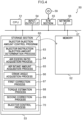
- An engine control system 10 illustrated in Fig. 1 controls injection amounts of respective injectors corresponding to plural cylinders of an engine.
- the engine control system 10 includes an air excess ratio detector 12, an air intake amount detector 14, a crank angle detector 16, an injector injection amount control device 18, and plural injectors 36A, 36B, 36C, and 36D.
- Fig. 2 illustrates a specific example of a configuration of the engine control system 10.
- the engine control system 10 controls the injection amounts of the plural injectors 36A, 36B, 36C, and 36D according to sensor information detected by the air excess ratio detector 12, the air intake amount detector 14, and the crank angle detector 16.
- the engine control system 10 further includes a supercharger 40 to increase the intake air pressure, an intercooler 42 to cool air that has increased in temperature due to compression by the supercharger 40, and an exhaust gas recirculation (EGR) cooler 44 to lower the temperature of high temperature exhaust gas.
- EGR exhaust gas recirculation
- the air excess ratio detector 12 successively detects an air excess ratio ⁇ sens of gas exhausted from the cylinders of the engine.
- the air intake amount detector 14 successively detects an air intake amount m af of air freshly taken into the cylinders of the engine.
- the crank angle detector 16 detects a measured value of a crank angle that is a rotation angle of a crankshaft of the engine.
- the injector injection amount control device 18 includes an injector instruction injection amount determination section 20, an air excess ratio acquisition section 22, an air intake amount acquisition section 24, a crank angle acquisition section 26, and a first correction section 28.
- the injector injection amount control device 18 further includes a torque estimation section 30, a second correction section 32, and an injector control section 34.
- the crank angle acquisition section 26 is an example of an acquisition section of the technology disclosed herein.
- the injector instruction injection amount determination section 20 is an example of a determination section of the technology disclosed herein.
- the torque estimation section 30 is an example of an estimation section of the technology disclosed herein.
- the first correction section 28 and the second correction section 32 are examples of a correction section of the technology disclosed herein.
- the injector instruction injection amount determination section 20 determines a target injection amount q trg as a target amount of fuel to be injected from an injector at respective timings for each of the injectors 36A, 36B, 36C, and 36D corresponding to the plural cylinders of the engine.
- the injector instruction injection amount determination section 20 also determines an instruction injection amount for the respective injectors as an injection amount to match the target injection amount q trg .
- the injector instruction injection amount determination section 20 determines the instruction injection amount to match the target injection amount q trg based on the engine revolution speed, throttle opening, torque demand, or the like.
- the air excess ratio acquisition section 22 successively acquires the air excess ratio ⁇ sens detected by the air excess ratio detector 12.
- the air intake amount acquisition section 24 successively acquires the air intake amount m af detected by the air intake amount detector 14.
- the crank angle acquisition section 26 successively acquires the measured value for the crank angle detected by the crank angle detector 16.
- the first correction section 28 corrects the instruction injection amount based on the air excess ratio ⁇ sens acquired by the air excess ratio acquisition section 22, the air intake amount m af acquired by the air intake amount acquisition section 24, and the instruction injection amount determined by the injector instruction injection amount determination section 20.
- the first correction section 28 uses Equation (1) below to calculate a calculated value q calc of the injector injection amount, according to a predetermined logical air-fuel ratio value L st , the air excess ratio ⁇ sens acquired by the air excess ratio acquisition section 22, and the air intake amount m af acquired by the air intake amount acquisition section 24.
- q calc m af ⁇ sens ⁇ L st
- the first correction section 28 calculates an engine revolution speed N e from the measured value of the crank angle acquired by the crank angle acquisition section 26.
- the first correction section 28 also uses Equation (2) below to calculate an estimate value q inj of the injector injection amount, according to the engine revolution speed N e , a fuel density ⁇ fuel , a number of cylinders N cy1 , and the calculated value q calc for the injector injection amount.
- q inj q calc ⁇ 120 ⁇ 1000 N e ⁇ ⁇ fuel ⁇ N cyl
- the first correction section 28 calculates a first correction coefficient, this being a correction coefficient to be applied to the instruction injection amount, such that the estimate value q inj of the injector injection amount approaches the target injection amount q trg .
- the first correction section 28 then multiplies the instruction injection amount determined by the injector instruction injection amount determination section 20 by the first correction coefficient to correct the instruction injection amount determined by the injector instruction injection amount determination section 20.
- the specific correction method for the instruction injection amount may for example employ proportional-integral-differential (PID) control, or may employ a method based on a map (table) prepared in advance.
- the torque estimation section 30 estimates the torque generated by each of the plural cylinders of the engine based on a non-linear Kalman filter employing an error between the measured value of the crank angle and an estimate value of the crank angle, and an error between a calculated value of a crank angular velocity and an estimate value of the crank angular velocity.
- the torque estimation section 30 first calculates the calculated value of the crank angular velocity, this being the rotation angular velocity of the crankshaft, from the measured value for the crank angle acquired by the crank angle acquisition section 26.
- the torque estimation section 30 uses Equation (3) below to calculate the error between a measured value ⁇ (k) of the crank angle acquired by the crank angle acquisition section 26 and an estimate value 0 ⁇ - (k) of the crank angle calculated using the non-linear Kalman filter, described later.
- ⁇ ⁇ k ⁇ k ⁇ ⁇ ⁇ ⁇ k
- k represents a cycle of an updated count.
- the torque estimation section 30 also uses Equation (4) below to calculate the error between a calculated value ⁇ ⁇ (k) of the crank angular velocity, and an estimate value 0 ⁇ - (k) of the crank angular velocity calculated using the non-linear Kalman filter, described later.
- ⁇ ⁇ ⁇ k ⁇ ⁇ k ⁇ ⁇ ⁇ ⁇ ⁇ k
- a state estimate value of the present exemplary embodiment includes the crank angle ⁇ (k), the crank angular velocity ⁇ ⁇ (k), and an indicated torque ⁇ (k), as illustrated in Equation (5) below.
- x k ⁇ k ⁇ ⁇ k ⁇ k
- Equations (6) and (7) below that employ a non-linear function f and a non-linear function h are used to calculate time series data for the crank angle and time series data for the crank angular velocity.
- v(k) is system noise
- ⁇ (k) is observation noise
- the non-linear function f and the non-linear function h are functions including desired coefficient functions, and in the present exemplary embodiment these are expressed by the non-linear formulae of Equations (7-1) to (7-4) below.
- the non-linear state formulae illustrated by Equations (7-1) to (7-4) above are input with the measured value ⁇ (k) for the crank angle at a current timing cycle k, the calculated value ⁇ ⁇ (k) for the crank angular velocity at the current timing cycle k, and the torque value ⁇ (k) at the current timing cycle k.
- a crank angle ⁇ (k+1) for a next timing cycle k+1, a crank angular velocity ⁇ ⁇ (k+1) for the next timing cycle k+1, and a torque ⁇ (k+1) for the next timing cycle k+1 are then predicted.
- a iner ( ⁇ ) is a term relating to inertia of a piston crank mechanism in the engine
- a gra ( ⁇ ) is a term relating to gravity of the piston crank mechanism
- a vel ( ⁇ ) is a term relating to angular velocity of the piston crank mechanism
- a fri ( ⁇ ) is a term relating to friction in the piston crank mechanism.
- a iner ( ⁇ ), a gra ( ⁇ ), a vel ( ⁇ ), and a fri ( ⁇ ) are coefficient functions.
- a term relating to inertia, a term relating to gravity, a term relating to angular velocity, and a term relating to friction can be expressed as illustrated in Equation (7-5) below by adding together after shifting in phase by 180°.
- a gra_s ( ⁇ ) is a coefficient function of the term relating to gravity of a single cylinder
- a vel_s ( ⁇ ) is a coefficient function of the term relating to the angular velocity of a single cylinder
- a fri_s ( ⁇ ) is a coefficient function of the term relating to friction of a single cylinder.
- equation computation portions of the above coefficient functions are calculated by substitution into a table expressing relationships between output values of these coefficient functions and the ⁇ values.
- a table is established in advance that expresses relationships between the crank angle ⁇ and the output value of the term a iner ⁇ relating to inertia, the output value of the term a gra ( ⁇ ) relating to gravity, the output value of the term a vel ( ⁇ ) relating to angular velocity, and the output value of the term a fri ( ⁇ ) relating to friction.
- the torque estimation section 30 sets an initial value for the state estimate value as in Equation (8) below.
- the torque estimation section 30 sets an initial value P(0) for a post-event error covariance matrix as in Equation (9) below.
- P 0 P 0
- a variance Q of system noise and a variance R of observation noise are also set.
- the torque estimation section 30 calculates 2n + 1 sigma points ⁇ ⁇ , ⁇ i as sample points respectively corresponding to the mean value and standard deviations from the state estimate value x ⁇ (k-1) and the covariance matrix P (k-1) of the previous cycle.
- ( ⁇ P) i represents the i th column of a matrix square root of the covariance matrix P.
- Weightings w o , w i applied to the respective sigma points are calculated using Equations (13), (14) below.
- ⁇ is a scaling parameter.
- a pre-event state estimate value and a pre-event error covariance matrix calculated using Equations (16) and (17) below are referred to as estimate values for a first order moment and a second order moment.
- the estimate values for the first order moment and second order moment have a precision up to a Taylor series expansion to second order of f(x(k), v(k)) for a desired non-linear function. Since estimate values to third order moment and above include additional error, ⁇ is a parameter to adjust for the effect of such error. Semi-definiteness is guaranteed if ⁇ is selected so as to be 0 or above, ⁇ is often set to 0 normally.
- the torque estimation section 30 uses Equation (15) below to update the sigma point ⁇ i with the non-linear function f.
- the torque estimation section 30 uses Equation (16) below to calculate a pre-event state estimate value x ⁇ - (k) using a sigma point ⁇ i - (k) and the weighting wi.
- Equation (17) a pre-event error covariance matrix P - (k) from the sigma point ⁇ i - (k) and the pre-event state estimate value x ⁇ - (k).
- b is a coefficient matrix for system noise.
- the torque estimation section 30 uses Equations (18), (19), and (20) below to recalculate 2n+1 sigma points from the pre-event state estimate value x ⁇ - (k) and the pre-event error covariance matrix P - (k).
- the torque estimation section 30 uses Equation (21) below to calculate an output sigma point ⁇ i - (k) from the sigma point ⁇ i - (k) and the non-linear function f.
- the torque estimation section 30 uses Equation (22) below to calculate a pre-event output estimate value y ⁇ - (k) from the output sigma point ⁇ i - (k).
- the torque estimation section 30 uses Equation (23) below to calculate a pre-event output error covariance matrix P yy - (k) from the output sigma point ⁇ i - (k) and the pre-event output estimate value y ⁇ - (k).
- the torque estimation section 30 uses Equation (24) below to calculate a pre-event state/output error covariance matrix P xy - (k) from the pre-event state estimate value x ⁇ - (k) and the pre-event error covariance matrix P - (k), the output sigma point ⁇ i - (k), and the pre-event output estimate value y ⁇ - (k).
- the torque estimation section 30 uses Equation (25) below to calculate a Kalman gain g(k) from the pre-event state/output error covariance matrix P xy - (k), the pre-event output error covariance matrix P yy - (k), and the observation noise variance R.
- g k P xy ⁇ k P yy ⁇ k + R
- the torque estimation section 30 uses Equation (26) below to estimate a state estimate value x ⁇ (k) using the Kalman gain g(k), the error ⁇ (k) relating to the crank angle, and the error ⁇ ⁇ (k) relating to the crank angular velocity.
- x ⁇ k x ⁇ ⁇ k + g k ⁇ ⁇ k ⁇ ⁇ ⁇ k
- the torque estimation section 30 uses Equation (27) below to calculate an post-event error covariance matrix P(k) to be utilized on the next update, using the pre-event error covariance matrix P - (k), the pre-event state/output error covariance matrix P xy - (k), and the Kalman gain g(k).
- P k P ⁇ k ⁇ g k P xy ⁇ k T
- the torque estimation section 30 also estimates the torque arising in each cylinder based on the time series data for the indicated torque ⁇ (k) in the state estimate value x ⁇ (k).
- Fig. 3 is an explanatory diagram to explain processing to estimate the torque arising in each cylinder from the indicated torque ⁇ (k).
- the torque estimation section 30 estimates the indicated torque ⁇ (k) for respective timings.
- each of the cylinders ignites at a different timing.
- the rises in the indicated torque ⁇ (k) correspond to the torque arising in each cylinder.
- a crank rotor includes a missing tooth portion where a tooth is missing in order to detect an absolute angle of the crank angle.
- the cylinder corresponding to the torque arising at a given timing in the indicated torque ⁇ (k) is identified according to position information of the missing tooth portion of the crank rotor.
- the torque estimation section 30 identifies ranges of the indicated torque ⁇ (k) corresponding to each of the cylinders based on a relationship between a crank angle range corresponding to the missing tooth portion appearing in the indicated torque ⁇ (k) and the ignition sequence of the cylinders, and associates these ranges with cylinder numbers.
- the torque estimation section 30 estimates an average of the indicated torque ⁇ (k) values at each timing within a range identified as corresponding to that cylinder as the torque value for that cylinder. Note that the torque estimation section 30 employs the values of the indicated torque ⁇ (k) in crank angle ranges not including the missing tooth portion of the crank rotor to calculate the average of the indicated torque ⁇ (k) values.
- the second correction section 32 corrects the injection amounts of the respective injectors corresponding to the plural cylinders such that the torques arising in the plural cylinders as estimated by the torque estimation section 30 will fall within the same range.
- the second correction section 32 calculates second correction coefficients for the injection amounts of the respective injectors corresponding to the cylinders such that the respective torque values of the cylinders as estimated by the torque estimation section 30 become uniform. The second correction section 32 then corrects the instruction injection amounts corrected by the first correction section 28 using the second correction coefficients.
- the injector 36A is installed corresponding to a cylinder A
- the injector 36B is installed corresponding to a cylinder B
- the injector 36C is installed corresponding to a cylinder C
- the injector 36D is installed corresponding to a cylinder D.
- the second correction section 32 calculates a proportional torque from the average torque across all cylinders and the torque of a given cylinder based on the torques of each of the cylinders estimated by the torque estimation section 30, and calculates the second correction coefficients for the injection amounts of the respective injectors such that the proportional torque becomes 1.
- the second correction section 32 calculates the second correction coefficient to be applied to the injector 36A such that the proportional torque ( ⁇ A / ⁇ - ) becomes 1.
- the second correction coefficient to be applied to the injector 36A may alternatively be calculated such that a proportional torque ( ⁇ - / ⁇ A ) becomes 1.
- the second correction section 32 similarly calculates the second correction coefficients for the injectors 36B, 36C, and 36D. The injection amount of each of the injectors is thus corrected such that the torques arising in the plural cylinders falls into the same range.
- the injector control section 34 controls driving of the injectors 36A to 36D according to the injection amounts of the respective injectors as corrected by the second correction section 32. Specifically, the injector control section 34 controls driving of the injectors 36Ato 36D such that the injection amounts of the respective injectors as corrected by the second correction section 32 are injected by the respective injectors.
- the injector injection amount control device 18 may, for example, be implemented by a computer 50, illustrated in Fig. 4 .
- the computer 50 includes a CPU 51, memory 52 serving as a temporary storage region, and a non-volatile storage section 53.
- the computer 50 further includes an input/output interface (I/F) 54 to which input/output devices (not illustrated in the drawings) such as respective sensors, a display device, and an input device are connected, and a read/write (R/W) section 55 that controls reading and writing of data to and from a recording medium 59.
- the computer 50 further includes a network I/F 56 connected to a network such as the internet.
- the CPU 51, the memory 52, the storage section 53, the input/output I/F 54, the R/W section 55, and the network I/F 56 are connected together through a bus 57.
- the storage section 53 may be implemented by a hard disk drive (HDD), a solid state drive (SSD), flash memory, or the like.
- the storage section 53 serving as a storage medium, is stored with an injector injection amount control program 60 for causing the computer 50 to function as the injector injection amount control device 18.
- the injector injection amount control program 60 includes an injector instruction injection amount determination process 63, an air excess ratio acquisition process 64, an air intake amount acquisition process 65, and a crank angle acquisition process 66.
- the injector injection amount control program 60 further includes a first correction process 67, a torque estimation process 68, a second correction process 69, and an injector control process 70.
- the CPU 51 reads the injector injection amount control program 60 from the storage section 53 and expands the injector injection amount control program 60 in the memory 52, and executes the processes of the injector injection amount control program 60 in sequence.
- the CPU 51 operates as the injector instruction injection amount determination section 20 illustrated in Fig. 1 by executing the injector instruction injection amount determination process 63.
- the CPU 51 operates as the air excess ratio acquisition section 22 illustrated in Fig. 1 by executing the air excess ratio acquisition process 64.
- the CPU 51 operates as the air intake amount acquisition section 24 illustrated in Fig. 1 by executing the air intake amount acquisition process 65.
- the CPU 51 operates as the crank angle acquisition section 26 illustrated in Fig. 1 by executing the crank angle acquisition process 66.
- the CPU 51 operates as the first correction section 28 illustrated in Fig.
- the CPU 51 operates as the torque estimation section 30 illustrated in Fig. 1 by executing the torque estimation process 68.
- the CPU 51 operates as the second correction section 32 illustrated in Fig. 1 by executing the second correction process 69.
- the CPU 51 operates as the injector control section 34 illustrated in Fig. 1 by executing the injector control process 70.
- the computer 50 executing the injector injection amount control program 60 thus functions as the injector injection amount control device 18.
- the CPU 51 corresponds to hardware that executes the injector injection amount control program 60 corresponding to software.
- the functionality implemented by the injector injection amount control program 60 may, for example, be implemented by a semiconductor integrated circuit, more specifically by an application specific integrated circuit (ASIC) or the like.
- ASIC application specific integrated circuit
- the injector injection amount control device 18 executes the injection amount control processing illustrated in Fig. 5 .
- the first correction section 28 calculates the first correction coefficient configuring a correction coefficient to be applied to the corresponding instruction injection amount such that the estimate value q inj of the injector injection amount approaches the target injection amount q trg .
- the first correction section 28 then multiplies the instruction injection amount determined by the injector instruction injection amount determination section 20 by the first correction coefficient so as to correct the instruction injection amount determined by the injector instruction injection amount determination section 20.
- Step S80 is implemented by the first correction processing illustrated in Fig. 6 .
- the torque estimation section 30 estimates the torque of each cylinder based on the non-linear Kalman filter employing the error between the measured value of the crank angle and the estimate value of the crank angle and the error between the calculated value of the crank angular velocity and the estimate value of the crank angular velocity.
- Step S82 is implemented by the torque estimation processing illustrated in Fig. 7 .
- the second correction section 32 further corrects the instruction injection amounts of the respective injectors corresponding to the plural cylinders such that the respective torques arising in the plural cylinders as estimated at step S82 become uniform.
- Step S84 is implemented by the second correction processing illustrated in Fig. 8 .
- crank angle acquisition section 26 acquires the measured value ⁇ (k) for the crank angle detected by the crank angle detector 16.
- the air excess ratio acquisition section 22 acquires the air excess ratio ⁇ sens detected by the air excess ratio detector 12.
- the air intake amount acquisition section 24 acquires the air intake amount m af detected by the air intake amount detector 14.
- the first correction section 28 uses Equation (1) to calculate the calculated value q calc of the corresponding injector injection amount according to the predetermined logical air-fuel ratio value L st , the air excess ratio ⁇ sens acquired at step S 102, and the air intake amount m af acquired at step S104.
- the first correction section 28 calculates the engine revolution speed N e from the measured value of the crank angle acquired at step S 100.
- the first correction section 28 uses Equation (2) to calculate the estimate value q inj of the injector injection amount based on the engine revolution speed N e , the fuel density ⁇ fuel , the number of cylinders N cyl , and the calculated fuel amount value q calc .
- the first correction section 28 calculates the first correction coefficient, this being a correction coefficient to be applied to the instruction injection amount, such that the estimate value q inj for the injector injection amount approaches the target injection amount q trg .
- the first correction section 28 multiplies the instruction injection amount determined by the injector instruction injection amount determination section 20 by the first correction coefficient to correct the instruction injection amount. This completes the first correction processing.
- the torque estimation section 30 acquires the measured value of the crank angle acquired at step S100 of the first correction processing.
- the torque estimation section 30 calculates a calculated value of the crank angular velocity from the measured value ⁇ (k) of the crank angle acquired at step S200.
- the torque estimation section 30 uses Equation (3) to calculate the error ⁇ (k) between the measured value ⁇ (k) of the crank angle acquired at step S200 and the estimate value ⁇ ⁇ - (k) of the crank angle calculated at a previous step using the non-linear Kalman filter.
- the torque estimation section 30 uses Equation (4) to calculate the error ⁇ ⁇ (k) between the calculated value ⁇ ⁇ (k) of the crank angular velocity obtained at step S202 and the estimate value ⁇ ⁇ - (k) of the crank angular velocity calculated at a previous step using the non-linear Kalman filter.
- the torque estimation section 30 uses Equation (26) to estimate the state estimate value x ⁇ (k) employing the error ⁇ (k) relating to the crank angle obtained at step S204, and the error ⁇ ⁇ (k) relating to the crank angular velocity obtained at step S206.
- the torque estimation section 30 estimates the torque arising in each cylinder based on the indicated torque ⁇ (k) in the state estimate value x ⁇ (k). Specifically, the torque estimation section 30 estimates the mean value of the indicated torque ⁇ (k) at each timing within the identified range for each of the cylinders based on the indicated torque ⁇ (k) as the torque value for each of the cylinders.
- the torque estimation section 30 outputs the torque of each of the cylinders as estimated at step S210 as a result, thus completing the torque estimation processing.
- the second correction section 32 calculates the average torque based on the torque of each of the cylinders output in a predetermined time segment at step S212 of the torque estimation processing.
- the second correction section 32 calculates the proportional torque of each of the cylinders from the average torque calculated at step S300 and the torques of the respective cylinders.
- the second correction section 32 calculates the second correction coefficient to be applied to the instruction injection amount of the injector of each of the cylinders such that the proportional torque calculated at step S302 becomes 1.
- the second correction coefficients are calculated for each of the injectors.
- the second correction section 32 further corrects the instruction injection amounts corrected in the first correction processing described above by multiplying the instruction injection amounts by the second correction coefficients calculated at step S304 to be applied to the respective injectors corresponding to the cylinders.
- the second correction section 32 outputs the instruction injection amounts for the respective injectors corrected at step S306 as results.
- the injector control section 34 then controls driving of the respective injectors 36Ato 36D such that the injection amounts of the respective injectors as corrected by the second correction section 32 are injected by the respective injectors.
- the injector injection amount control device estimates the torques arising in the plural cylinders of an engine based on a non-linear Kalman filter employing the error between the measured value of the crank angle and the estimate value of the crank angle.
- the injector injection amount control device then corrects the injection amounts of the respective injectors corresponding to the plural cylinders such that the plural torques fall within the same range. This enables variation in the fuel injection amounts of the respective cylinders of the engine to be suppressed without the installation of additional predetermined sensors in the engine system.
- Existing onboard sensors in a vehicle can be employed to suppress variation in the injection amounts of the respective cylinders that arises as a result of degradation over time. Moreover, suppressing variation in the injection amounts of the injectors enables a downturn in exhaust gas performance and fuel efficiency performance of the engine according to degradation of the injectors over time to be reduced.
- Fig. 9 illustrates comparison results for a simulated case of an increased injection amount in the No. 1 cylinder under predetermined conditions, between the proportional torque of each cylinder in a case in which the present exemplary embodiment has been applied (the solid line in Fig. 9 ), and the proportional torque of each cylinder in a case in which the present exemplary embodiment has not been applied (the dashed line in Fig. 9 ).
- the vertical axis represents the proportional torque
- the horizontal axis represents the cylinder numbers. It can be seen that applying the present exemplary embodiment enables variation in torque between the cylinders to be suppressed.
- Fig. 10 illustrates comparison results for variation in injection amounts under nine different test conditions in a case in which the present exemplary embodiment has been applied (the solid line in Fig. 10 ) and a case in which the present exemplary embodiment has not been applied (the dashed line in Fig. 10 ).
- the vertical axis represents absolute values of the variation in the injection amounts
- the horizontal axis represents the test conditions.
- the mean value of the absolute values of the variation in the injection amounts for the nine conditions was 4.49 (mm 3 /st) without the present exemplary embodiment being applied, and was 1.16 (mm 3 /st) with the present exemplary embodiment being applied. It was thus confirmed that the present exemplary embodiment is capable of greatly suppressing variation in the injection amounts.
- the present exemplary embodiment is capable of suppressing variation in the fuel injection amounts of the injectors, and is also capable of reducing a downturn in the exhaust gas performance and fuel efficiency performance of an engine due to degradation of the injectors over time.
- An engine control system of the second exemplary embodiment differs from that of the first exemplary embodiment in the point of being applied with a diesel particulate filter (DPF) combustion-based regeneration control system that regenerates by combusting particulate matter (PM) that has accumulated on the DPF.
- DPF diesel particulate filter
- PM particulate matter
- a DPF combustion-based regeneration control system 210 illustrated in Fig. 11 includes an entry port temperature detector 11, an air excess ratio detector 12, a differential pressure detector 13, an air intake amount detector 14, a crank angle detector 16, and an injector injection amount control device 218.
- the DPF combustion-based regeneration control system 210 further includes plural injectors 36A, 36B, 36C, and 36D.
- Fig. 12 illustrates a specific example of a configuration of the DPF combustion-based regeneration control system 210.
- the DPF combustion-based regeneration control system 210 controls the injection amounts of the plural injectors 36A, 36B, 36C, and 36D according to sensor information detected by the entry port temperature detector 11, the air excess ratio detector 12, the differential pressure detector 13, the air intake amount detector 14, and the crank angle detector 16.
- exhaust gas from the engine passes through a diesel oxidation catalyst (DOC) and reaches a diesel particulate filter DPF.
- DOC diesel oxidation catalyst
- Fig. 13 is an explanatory diagram to explain the structure of the diesel particulate filter DPF.
- exhaust gas enters the diesel particulate filter DPF through an entry port and particulate matter PM contained in the exhaust gas is filtered out.
- the entry port temperature detector 11 detects the temperature at the entry port of the diesel particulate filter DPF.
- the differential pressure detector 13 detects differential pressure representing the difference in pressure between the entry port of the diesel particulate filter DPF and an exit port of the diesel particulate filter DPF.
- the injector injection amount control device 218 includes an injector instruction injection amount determination section 220, an air excess ratio acquisition section 22, an air intake amount acquisition section 24, a crank angle acquisition section 26, a temperature acquisition section 219, and a PM buildup amount estimation section 223.
- the injector injection amount control device 218 further includes a first correction section 28, a torque estimation section 30, a second correction section 32, and an injector control section 34.
- the PM buildup amount estimation section 223 is an example of a buildup amount estimation section of the technology disclosed herein.
- the temperature acquisition section 219 acquires the temperature at the entry port of the diesel particulate filter DPF detected by the entry port temperature detector 11.
- the PM buildup amount estimation section 223 acquires the differential pressure detected by the differential pressure detector 13. The PM buildup amount estimation section 223 then estimates the amount of particulate matter PM buildup that has accumulated on the diesel particulate filter DPF according to the differential pressure.
- the injector instruction injection amount determination section 220 determines the injector instruction injection amounts based on the particulate matter PM buildup amount estimated by the PM buildup amount estimation section 223 and the temperature at the entry port of the diesel particulate filter DPF acquired by the temperature acquisition section 219.
- the injector instruction injection amount determination section 220 calculates injector instruction injection amounts so as to control such that the temperature value at the entry port of the diesel particulate filter DPF reaches a predetermined temperature until the particulate matter PM buildup amount reaches a predetermined value or lower.
- the control method employed therefor may be PID control, control based on a map (table) prepared in advance, or the like.
- the first correction section 28 and the second correction section 32 of the second exemplary embodiment determines the injector instruction injection amounts similarly to in the first exemplary embodiment.
- the injector injection amount control device 218 may, for example, be implemented by the computer 50 illustrated in Fig. 14 .
- the computer 50 includes a CPU 51, memory 52 serving as a temporary storage region, and a non-volatile storage section 53.
- the computer 50 further includes an input/output I/F 54 to which input/output devices (not illustrated in the drawings) such as respective sensors, a display device, and an input device are connected, and a R/W section 55 that controls reading and writing of data to and from a recording medium 59.
- the computer 50 further includes a network I/F 56 connected to a network such as the internet.
- the CPU 51, the memory 52, the storage section 53, the input/output I/F 54, the R/W section 55, and the network I/F 56 are connected together through a bus 57.
- the storage section 53 may be implemented by an HDD, an SSD, flash memory, or the like.
- the storage section 53 serving as a storage medium, is stored with an injector injection amount control program 260 for causing the computer 50 to function as the injector injection amount control device 218.
- the injector injection amount control program 260 includes a temperature acquisition process 261, a PM buildup amount estimation process 262, an injector instruction injection amount determination process 263, an air excess ratio acquisition process 64, and an air intake amount acquisition process 65.
- the injector injection amount control program 260 further includes a crank angle acquisition process 66, a first correction process 67, a torque estimation process 68, a second correction process 69, and an injector control process 70.
- the CPU 51 reads the injector injection amount control program 260 from the storage section 53 and expands the injector injection amount control program 260 in the memory 52, and executes the processes of the injector injection amount control program 260 in sequence.
- the CPU 51 operates as the temperature acquisition section 219 illustrated in Fig. 11 by executing the temperature acquisition process 261.
- the CPU 51 operates as the PM buildup amount estimation section 223 illustrated in Fig. 11 by executing the PM buildup amount estimation process 262.
- the CPU 51 operates as the injector instruction injection amount determination section 220 illustrated in Fig. 11 by executing the injector instruction injection amount determination process 263.
- the CPU 51 operates as the air excess ratio acquisition section 22 illustrated in Fig. 11 by executing the air excess ratio acquisition process 64.
- the CPU 51 operates as the air intake amount acquisition section 24 illustrated in Fig.
- the CPU 51 operates as the crank angle acquisition section 26 illustrated in Fig. 11 by executing the crank angle acquisition process 66.
- the CPU 51 operates as the first correction section 28 illustrated in Fig. 11 by executing the first correction process 67.
- the CPU 51 operates as the torque estimation section 30 illustrated in Fig. 11 by executing the torque estimation process 68.
- the CPU 51 operates as the second correction section 32 illustrated in Fig. 11 by executing the second correction process 69.
- the CPU 51 operates as the injector control section 34 illustrated in Fig. 11 by executing the injector control process 70.
- the computer 50 executing the injector injection amount control program 260 thus functions as the injector injection amount control device 218.
- the CPU 51 corresponds to hardware that executes the injector injection amount control program 260 corresponding to software.
- injector injection amount control program 260 may, for example, be implemented by a semiconductor integrated circuit, more specifically by an ASIC or the like.
- the injector injection amount control device determines the instruction injection amounts for the injectors based on the buildup amount of the particulate matter PM and the temperature at the entry port of the diesel particulate filter DPF. The injector injection amount control device then corrects the injector injection amounts. This enables variation in the fuel injection amounts between the injectors to be suppressed, even during combustion-based regeneration of the diesel particulate filter DPF. This also enables a downturn in exhaust gas performance and fuel efficiency performance of the engine due to degradation of the injectors over time to be reduced.
- the third exemplary embodiment differs from the second exemplary embodiment in the point that an injector is installed inside an exhaust pipe. Note that sections having similar configurations to those in the first or second exemplary embodiments are allocated the same reference numerals, and explanation thereof is omitted.
- a DPF combustion-based regeneration control system 310 illustrated in Fig. 15 includes an entry port temperature detector 11, an air excess ratio detector 12, a differential pressure detector 13, an air intake amount detector 14, a crank angle detector 16, and an injector injection amount control device 318.
- the DPF combustion-based regeneration control system 310 further includes plural injectors 36A, 36B, 36C, 36D, and 36E.
- Fig. 16 illustrates a specific example of a configuration of the DPF combustion-based regeneration control system 310. As illustrated in Fig. 16 , in the third exemplary embodiment the injector 36E is installed inside an exhaust pipe of the engine system.
- the injector injection amount control device 318 includes an injector instruction injection amount determination section 320, an air excess ratio acquisition section 22, an air intake amount acquisition section 24, a crank angle acquisition section 26, a temperature acquisition section 219, and a PM buildup amount estimation section 223.
- the injector injection amount control device 318 further includes a first correction section 28, a torque estimation section 30, a second correction section 32, and an injector control section 34.
- the injector instruction injection amount determination section 320 determines an instruction injection amount for the injector installed inside the exhaust pipe of the engine.
- the first correction section 28 and the second correction section 32 of the third exemplary embodiment correct the injector instruction injection amount, similarly to in the first exemplary embodiment.
- the injector injection amount control device 318 may, for example, be implemented by the computer 50 illustrated in Fig. 14 .
- the storage section 53 serving as a storage medium is stored with an injector injection amount control program 360 for causing the computer 50 to function as the injector injection amount control device 318.
- the injector injection amount control program 360 includes a temperature acquisition process 261, a PM buildup amount estimation process 262, an injector instruction injection amount determination process 363, an air excess ratio acquisition process 64, and an air intake amount acquisition process 65.
- the injector injection amount control program 360 further includes a crank angle acquisition process 66, a first correction process 67, a torque estimation process 68, a second correction process 69, and an injector control process 70.
- the CPU 51 reads the injector injection amount control program 360 from the storage section 53 and expands the injector injection amount control program 360 in the memory 52, and executes the processes of the injector injection amount control program 360 in sequence.
- the CPU 51 operates as the injector instruction injection amount determination section 320 illustrated in Fig. 15 by executing the injector instruction injection amount determination process 363.
- the injector injection amount control device is capable of determining the instruction injection amount for the injector installed inside the exhaust pipe of the engine, and of correcting the instruction injection amount according to the torque of each of the cylinders.
- a program according to technology disclosed herein may be provided in a format recorded on a recording medium such as a CD-ROM, DVD-ROM, or USB memory.
Claims (14)
- Dispositif de commande de la quantité d'injection de l'injecteur (18, 218, 318), comprenant :une section d'acquisition (26) configurée pour acquérir une valeur mesurée d'un angle de vilebrequin qui est un angle de rotation d'un arbre de vilebrequin d'un moteur ;une section de détermination (20) configurée pour déterminer des quantités d'injection de l'instruction du carburant provenant des injecteurs respectifs, les injecteurs respectifs correspondant à a une pluralité de cylindres du moteur ;une section d'estimation (30) configurée pour estimer un couple survenant dans chaque cylindre de la pluralité de cylindres du moteur sur la base d'un filtre de Kalman non linéaire employant une erreur entre la valeur mesurée de l'angle de vilebrequin acquise par la section d'acquisition (26) et une valeur estimée de l'angle de vilebrequin, dans lequel :
la section d'estimation (30) est configurée en outre pour prédire l'angle de vilebrequin à une prochaine synchronisation, prédire la vitesse angulaire du vilebrequin à une prochaine synchronisation et prédire le couple à une prochaine synchronisation selon une formule non linéaire comportant un terme se rapportant à l'inertie du mécanisme piston-vilebrequin du moteur, un terme se rapportant à la gravité du mécanisme piston-vilebrequin, un terme se rapportant à la vitesse angulaire du mécanisme piston-vilebrequin et un terme se rapportant à la friction dans le mécanisme piston-vilebrequin dans le filtre de Kalman non linéaire, qui est entré avec une valeur mesurée de l'angle de vilebrequin à une synchronisation en cours, une valeur calculée de la vitesse angulaire du vilebrequin à la synchronisation en cours et une valeur du couple à la synchronisation en cours ; etune section de correction (28) configurée pour corriger les quantités d'injection de l'instruction pour les injecteurs respectifs correspondant à la pluralité de cylindres de sorte que chaque couple de la pluralité de couples estimés par la section d'estimation (30) tombe à l'intérieur de la même plage. - Dispositif de commande de la quantité d'injection de l'injecteur (18, 218, 318) selon la revendication 1, dans lequel la section d'estimation (30) est configurée en outre pour :calculer une valeur calculée de la vitesse angulaire du vilebrequin qui est une vitesse angulaire de rotation de l'arbre de vilebrequin provenant de la valeur mesurée de l'angle de vilebrequin acquis par la section d'acquisition (26) ; etestimer le couple de chaque cylindre de la pluralité de cylindres sur la base du filtre de Kalman non linéaire, le filtre de Kalman non linéaire employant une erreur entre la valeur mesurée de l'angle de vilebrequin et la valeur estimée de l'angle de vilebrequin et une erreur entre la valeur calculée de la vitesse angulaire du vilebrequin et une valeur estimée de la vitesse angulaire du vilebrequin.
- Dispositif de commande de la quantité d'injection de l'injecteur (18, 218, 318) selon la revendication 1 ou de la revendication 2, dans lequel la section de correction (28) est configurée en outre pour corriger en outre les quantités d'injection de l'instruction corrigées pour les injecteurs respectifs sur la base d'un rapport d'excès d'air du moteur, d'une quantité d'admissions d'air du moteur et des quantités d'injection de l'instruction corrigées des injecteurs respectifs.
- Dispositif de commande de la quantité d'injection de l'injecteur (18, 218, 318) selon la revendication 3, dans lequel la section de correction (28) est configurée en outre pour :calculer des valeurs estimées de quantités d'injection de carburant provenant des injecteurs respectifs en fonction d'une vitesse de rotation du moteur obtenue à partir de la valeur mesurée de l'angle de vilebrequin acquise par la section d'acquisition (26), du rapport d'excès d'air et de la quantité d'admissions d'air ; etcorriger en outre les quantités d'injection de l'instruction corrigées des injecteurs respectifs de sorte que les valeurs estimées des quantités d'injection des injecteurs respectifs se rapprochent des quantités d'injection cible des injecteurs respectifs.
- Dispositif de commande de la quantité d'injection de l'injecteur (18, 218, 318) selon la revendication 1, dans lequel la section d'estimation (30) est configurée en outre pour prédire l'angle de vilebrequin à une prochaine synchronisation, prédire la vitesse angulaire du vilebrequin à une prochaine synchronisation et prédire le couple à une prochaine synchronisation en employant un tableau exprimant les relations de l'angle de vilebrequin à une sortie de valeur par le terme se rapportant à l'inertie, à une sortie de valeur par le terme se rapportant à la gravité, à une sortie de valeur par le terme se rapportant à la vitesse angulaire et à une sortie de valeur par le terme se rapportant à la friction.
- Dispositif de commande de la quantité d'injection de l'injecteur (18, 218, 318) selon une quelconque revendication 1 à la revendication 5, dans lequel la section d'estimation (30) est configurée en outre pour estimer une valeur du couple sur la base de la plage d'un angle de vilebrequin correspondant à une position d'une partie de dent manquante d'un rotor de vilebrequin.
- Dispositif de commande de la quantité d'injection de l'injecteur (18, 218, 318) selon une quelconque revendication 1 à la revendication 6, dans lequel le filtre de Kalman non linéaire est un filtre de Kalman inodore.
- Dispositif de commande de la quantité d'injection de l'injecteur (18, 218, 318) selon une quelconque revendication 1 à la revendication 7, comprenant en outre une section d'estimation de la quantité d'augmentation (223) configurée pour estimer la quantité d'augmentation de matière particulaire accumulée dans un filtre à particules diesel,
dans lequel la section de détermination (20) est configurée en outre pour déterminer les quantités d'injection de l'instruction des injecteurs respectifs sur la base de la quantité d'augmentation estimée par la section d'estimation de la quantité d'augmentation (223) et de la température au niveau d'un orifice d'entrée du filtre à particules diesel. - Dispositif de commande de la quantité d'injection de l'injecteur (18, 218, 318) selon la revendication 8, dans lequel la section de détermination (20) est configurée en outre pour déterminer la quantité d'injection de l'instruction d'un injecteur, parmi les injecteurs respectifs, qui est installé à l'intérieur d'un tuyau d'échappement du moteur.
- Programme qui amène un dispositif de commande de la quantité d'injection de l'injecteur (18, 218, 318) à exécuter un processus comprenant :l'acquisition (S100) d'une valeur mesurée d'un angle de vilebrequin qui est un angle de rotation d'un arbre de vilebrequin d'un moteur à des synchronisations respectives ;la détermination (S106) des quantités d'injection de l'instruction de carburant provenant des injecteurs respectifs, les injecteurs respectifs correspondant à une pluralité de cylindres du moteur ;l'estimation (S208) d'un couple survenant dans chaque cylindre de la pluralité de cylindres du moteur sur la base d'un filtre de Kalman non linéaire employant une erreur entre la valeur mesurée acquise de l'angle de vilebrequin et une valeur estimée de l'angle de vilebrequin, dans lequel l'estimation comprend :
la prédiction de l'angle de vilebrequin à une prochaine synchronisation, la prédiction de la vitesse angulaire du vilebrequin à une prochaine synchronisation et la prédiction du couple à une prochaine synchronisation selon une formule non linéaire comportant un terme se rapportant à l'inertie du mécanisme piston-vilebrequin du moteur, un terme se rapportant à la gravité du mécanisme piston-vilebrequin, un terme se rapportant à la vitesse angulaire du mécanisme piston-vilebrequin et un terme se rapportant à la friction dans le mécanisme piston-vilebrequin dans le filtre de Kalman non linéaire, qui est entré avec une valeur mesurée de l'angle de vilebrequin à une synchronisation en cours, une valeur calculée de la vitesse angulaire du vilebrequin à la synchronisation en cours et une valeur du couple à la synchronisation en cours ; etla correction (S110) des quantités d'injection de l'instruction pour les injecteurs respectifs correspondant à la pluralité de cylindres de sorte que chaque couple de la pluralité de couples tombe à l'intérieur de la même plage. - Programme selon la revendication 10, comprenant en outre ;
le calcul d'une valeur calculée de la vitesse angulaire du vilebrequin qui est une vitesse angulaire de rotation de l'arbre de vilebrequin provenant de la valeur mesurée acquise par l'angle de vilebrequin ; et l'estimation du couple de chaque cylindre de la pluralité de cylindres sur la base du filtre de Kalman non linéaire, le filtre de Kalman non linéaire employant une erreur entre la valeur mesurée de l'angle de vilebrequin et la valeur estimée de l'angle de vilebrequin et une erreur entre la valeur calculée de la vitesse angulaire du vilebrequin et une valeur estimée de la vitesse angulaire du vilebrequin. - Programme selon la revendication 10 ou de la revendication 11, comprenant en outre la correction en outre des quantités d'injection de l'instruction corrigées pour les injecteurs respectifs sur la base d'un rapport d'excès d'air du moteur, d'une quantité d'admissions d'air du moteur et des quantités d'injection de l'instruction corrigées des injecteurs respectifs.
- Support d'informations mémorisé avec un programme qui amène un dispositif de commande de la quantité d'injection de l'injecteur (18, 218, 318) à exécuter un processus comprenant :l'acquisition (S100) d'une valeur mesurée d'un angle de vilebrequin qui est un angle de rotation d'un arbre de vilebrequin d'un moteur ;la détermination (S106) des quantités d'injection de l'instruction de carburant provenant des injecteurs respectifs, les injecteurs respectifs correspondant à une pluralité de cylindres du moteur ;l'estimation (S208) d'un couple survenant dans chaque cylindre de la pluralité de cylindres du moteur sur la base d'un filtre de Kalman non linéaire employant une erreur entre la valeur mesurée acquise de l'angle de vilebrequin et une valeur estimée de l'angle de vilebrequin, dans lequel l'estimation comprend :
la prédiction de l'angle de vilebrequin à une prochaine synchronisation, la prédiction de la vitesse angulaire du vilebrequin à une prochaine synchronisation et la prédiction du couple à une prochaine synchronisation selon une formule non linéaire comportant un terme se rapportant à l'inertie du mécanisme piston-vilebrequin du moteur, un terme se rapportant à la gravité du mécanisme piston-vilebrequin, un terme se rapportant à la vitesse angulaire du mécanisme piston-vilebrequin et un terme se rapportant à la friction dans le mécanisme piston-vilebrequin dans le filtre de Kalman non linéaire, qui est entré avec une valeur mesurée de l'angle de vilebrequin à une synchronisation en cours, une valeur calculée de la vitesse angulaire du vilebrequin à la synchronisation en cours et une valeur du couple à la synchronisation en cours ; etla correction (S110) des quantités d'injection de l'instruction pour les injecteurs respectifs correspondant à la pluralité de cylindres de sorte que chaque couple de la pluralité de couples tombe à l'intérieur de la même plage. - Procédé de commande de la quantité d'injection de l'injecteur qui amène un ordinateur à exécuter un processus comprenant :l'acquisition (S100) d'une valeur mesurée d'un angle de vilebrequin qui est un angle de rotation d'un arbre de vilebrequin d'un moteur ;la détermination (S106) des quantités d'injection de l'instruction de carburant provenant des injecteurs respectifs, les injecteurs respectifs correspondant à une pluralité de cylindres du moteur ;l'estimation (S208) d'un couple survenant dans chaque cylindre de la pluralité de cylindres du moteur sur la base d'un filtre de Kalman non linéaire employant une erreur entre la valeur mesurée acquise de l'angle de vilebrequin et une valeur estimée de l'angle de vilebrequin, dans lequel l'estimation comprend : la prédiction de l'angle de vilebrequin à une prochaine synchronisation, la prédiction de la vitesse angulaire du vilebrequin à une prochaine synchronisation et la prédiction du couple à une prochaine synchronisation selon une formule non linéaire comportant un terme se rapportant à l'inertie du mécanisme piston-vilebrequin du moteur, un terme se rapportant à la gravité du mécanisme piston-vilebrequin, un terme se rapportant à la vitesse angulaire du mécanisme piston-vilebrequin et un terme se rapportant à la friction dans le mécanisme piston-vilebrequin dans le filtre de Kalman non linéaire, qui est entré avec une valeur mesurée de l'angle de vilebrequin à une synchronisation en cours, une valeur calculée de la vitesse angulaire du vilebrequin à la synchronisation en cours et une valeur du couple à la synchronisation en cours ; etla correction (S110) des quantités d'injection de l'instruction pour les injecteurs respectifs correspondant à la pluralité de cylindres de sorte que chaque couple de la pluralité de couples tombe à l'intérieur de la même plage.
Applications Claiming Priority (1)
| Application Number | Priority Date | Filing Date | Title |
|---|---|---|---|
| PCT/JP2017/034394 WO2019058534A1 (fr) | 2017-09-22 | 2017-09-22 | Dispositif et procédé de commande de quantité d'injection d'injecteur, programme et support d'informations |
Publications (3)
| Publication Number | Publication Date |
|---|---|
| EP3686417A1 EP3686417A1 (fr) | 2020-07-29 |
| EP3686417A4 EP3686417A4 (fr) | 2020-10-14 |
| EP3686417B1 true EP3686417B1 (fr) | 2023-04-05 |
Family
ID=65810689
Family Applications (1)
| Application Number | Title | Priority Date | Filing Date |
|---|---|---|---|
| EP17926001.3A Active EP3686417B1 (fr) | 2017-09-22 | 2017-09-22 | Dispositif et procédé de commande de quantité d'injection d'injecteur, programme et support d'informations |
Country Status (4)
| Country | Link |
|---|---|
| US (1) | US11085388B2 (fr) |
| EP (1) | EP3686417B1 (fr) |
| JP (1) | JP6843255B2 (fr) |
| WO (1) | WO2019058534A1 (fr) |
Families Citing this family (2)
| Publication number | Priority date | Publication date | Assignee | Title |
|---|---|---|---|---|
| US10922203B1 (en) * | 2018-09-21 | 2021-02-16 | Nvidia Corporation | Fault injection architecture for resilient GPU computing |
| WO2020174542A1 (fr) * | 2019-02-25 | 2020-09-03 | 株式会社トランストロン | Dispositif d'estimation de couple de moteur, procédé d'estimation de couple de moteur et dispositif de commande de moteur |
Family Cites Families (32)
| Publication number | Priority date | Publication date | Assignee | Title |
|---|---|---|---|---|
| KR940002957B1 (ko) * | 1988-06-29 | 1994-04-09 | 미쯔비시지도오샤고오교오 가부시기가이샤 | 내연기관의 공연비제어방법 및 장치 |
| JPH10159637A (ja) | 1996-11-29 | 1998-06-16 | Denso Corp | 内燃機関の燃料噴射制御装置及び燃料噴射制御方法 |
| JPH11343911A (ja) | 1998-03-31 | 1999-12-14 | Mazda Motor Corp | 筒内噴射式エンジンの燃料制御装置 |
| US7497078B2 (en) * | 2002-10-16 | 2009-03-03 | Mitsubishi Fuso Truck And Bus Corporation | Exhaust emission control device of internal combustion engine |
| JP2005016328A (ja) * | 2003-06-24 | 2005-01-20 | Toyota Motor Corp | 複数の気筒を備える内燃機関の制御装置 |
| JP4446840B2 (ja) * | 2004-08-30 | 2010-04-07 | 株式会社日本自動車部品総合研究所 | 堆積量推定装置 |
| JP4665633B2 (ja) * | 2005-07-12 | 2011-04-06 | 株式会社デンソー | 内燃機関の排気浄化装置 |
| JP4438708B2 (ja) * | 2005-07-13 | 2010-03-24 | マツダ株式会社 | エンジンの燃料噴射制御装置 |
| JP4840288B2 (ja) | 2006-11-14 | 2011-12-21 | 株式会社デンソー | 燃料噴射装置及びその調整方法 |
| JP4928335B2 (ja) * | 2007-04-17 | 2012-05-09 | 日野自動車株式会社 | 排気浄化装置 |
| JP4803107B2 (ja) * | 2007-05-15 | 2011-10-26 | トヨタ自動車株式会社 | 内燃機関の排気浄化装置 |
| JP4930215B2 (ja) * | 2007-06-25 | 2012-05-16 | 株式会社デンソー | 排気浄化装置 |
| JP4462327B2 (ja) | 2007-10-26 | 2010-05-12 | 株式会社デンソー | 気筒特性ばらつき検出装置 |
| EP2136056A1 (fr) * | 2008-06-19 | 2009-12-23 | Continental Automotive GmbH | Correction de couple individuel de cylindre |
| JP2010127219A (ja) | 2008-11-28 | 2010-06-10 | Mitsubishi Fuso Truck & Bus Corp | ディーゼルエンジンの燃料制御装置 |
| JP2010144647A (ja) * | 2008-12-19 | 2010-07-01 | Mitsubishi Fuso Truck & Bus Corp | ディーゼルエンジンの燃料制御装置 |
| JP5182157B2 (ja) * | 2009-03-04 | 2013-04-10 | 日産自動車株式会社 | ディーゼルエンジンの制御装置 |
| JP5103459B2 (ja) | 2009-10-30 | 2012-12-19 | 日立オートモティブシステムズ株式会社 | エンジンの制御装置 |
| DE102009056381B4 (de) * | 2009-11-30 | 2014-05-22 | Mtu Friedrichshafen Gmbh | Verfahren zur Steuerung und Regelung einer Brennkraftmaschine |
| JP5793935B2 (ja) * | 2011-04-25 | 2015-10-14 | 日産自動車株式会社 | 内燃機関の点火時期制御装置及び点火時期制御方法 |
| EP2703629B1 (fr) * | 2011-04-28 | 2017-10-25 | Toyota Jidosha Kabushiki Kaisha | Dispositif de commande pour moteur à combustion interne |
| RU2014102419A (ru) * | 2011-07-28 | 2015-09-10 | Тойота Дзидося Кабусики Кайся | Устройство управления двигателем внутреннего сгорания |
| DE102012210301B3 (de) * | 2012-06-19 | 2013-09-05 | Continental Automotive Gmbh | Bestimmen der in einem Zylinder einer Brennkraftmaschine freigesetzten Energiemenge mittels einer Auswertung von Zahnzeiten einer mit einer Kurbelwelle verbundenen Geberscheibe |
| JP6136510B2 (ja) * | 2013-04-16 | 2017-05-31 | いすゞ自動車株式会社 | 噴射制御方法及び噴射制御装置 |
| JP6447097B2 (ja) * | 2014-12-19 | 2019-01-09 | いすゞ自動車株式会社 | 排気浄化システム |
| JP6582871B2 (ja) * | 2015-10-27 | 2019-10-02 | 富士通株式会社 | エンジントルク推定装置、エンジントルク推定システム及びエンジントルク推定方法 |
| JP6540668B2 (ja) * | 2016-11-25 | 2019-07-10 | トヨタ自動車株式会社 | ハイブリッド自動車 |
| JP6468298B2 (ja) * | 2017-01-30 | 2019-02-13 | トヨタ自動車株式会社 | ハイブリッド自動車 |
| JP6776975B2 (ja) * | 2017-03-29 | 2020-10-28 | トヨタ自動車株式会社 | 自動車 |
| US10119490B1 (en) * | 2017-05-03 | 2018-11-06 | Ford Global Technologies, Llc | Methods and systems for central fuel injection |
| US10167806B2 (en) * | 2017-05-03 | 2019-01-01 | Ford Global Technologies, Llc | Methods and system for central fuel injection |
| US10287994B2 (en) * | 2017-05-12 | 2019-05-14 | GM Global Technology Operations LLC | Electronic throttle control using model predictive control |
-
2017
- 2017-09-22 EP EP17926001.3A patent/EP3686417B1/fr active Active
- 2017-09-22 JP JP2019542935A patent/JP6843255B2/ja active Active
- 2017-09-22 WO PCT/JP2017/034394 patent/WO2019058534A1/fr unknown
-
2020
- 2020-03-19 US US16/824,593 patent/US11085388B2/en active Active
Also Published As
| Publication number | Publication date |
|---|---|
| EP3686417A4 (fr) | 2020-10-14 |
| EP3686417A1 (fr) | 2020-07-29 |
| WO2019058534A1 (fr) | 2019-03-28 |
| JP6843255B2 (ja) | 2021-03-17 |
| US20200217259A1 (en) | 2020-07-09 |
| US11085388B2 (en) | 2021-08-10 |
| JPWO2019058534A1 (ja) | 2020-10-22 |
Similar Documents
| Publication | Publication Date | Title |
|---|---|---|
| US9784644B2 (en) | Engine error detection system | |
| US7292931B2 (en) | Model-based inlet air dynamics state characterization | |
| JP4487745B2 (ja) | センサ応答特性検出装置 | |
| EP2444607B1 (fr) | Dispositif d'estimation des émissions de particules pour moteur diesel | |
| JP4622719B2 (ja) | Pm堆積量推定装置 | |
| US8353201B2 (en) | Intake air temperature rationality diagnostic | |
| US11085388B2 (en) | Injector injection amount control device, injector injection amount control method, and storage medium | |
| KR101734240B1 (ko) | 녹스 발생량 예측 장치 및 이를 이용한 녹스 발생량 예측 방법 | |
| US20150032359A1 (en) | Method of correcting operating set points of an internal combustion engine | |
| JP2009115012A (ja) | 内燃機関の空燃比制御装置 | |
| JP5331613B2 (ja) | 内燃機関の筒内ガス量推定装置 | |
| US7793641B2 (en) | Model-based fuel control for engine start and crank-to-run transition | |
| US10240546B2 (en) | Method and device for operating an internal combustion engine | |
| JP2008215204A (ja) | 内燃機関の熱発生率のシミュレーション方法、内燃機関のトルクモデル作成方法および内燃機関のトルク推定方法 | |
| US9970377B2 (en) | Method of correcting a standard characteristic curve of a standard fuel injector of an internal combustion engine | |
| JP4623456B2 (ja) | 速度変化に基づくエンジン空気量予測方法 | |
| US20190017449A1 (en) | Method for calculating a residual gas mass in a cylinder of an internal combustion engine and controller | |
| Jung et al. | A flywheel error compensation algorithm for engine misfire detection | |
| Tigelaar et al. | Utilization of turbocharger speed data to increase engine power and improve air path control strategy and diagnostics | |
| JP6888409B2 (ja) | ピストン温度推定装置及びピストン温度推定方法 | |
| JP2010096021A (ja) | 内燃機関の燃焼状態診断装置 | |
| GB2503219A (en) | Method of operating an internal combustion engine | |
| US10590870B2 (en) | Method of calculating exhaust gas recirculation rate using combustion pressure of cylinder | |
| JP2754568B2 (ja) | 内燃機関の燃料噴射量制御装置 | |
| US20240011425A1 (en) | Method, processing unit, and computer program for ascertaining fill levels of a first exhaust gas catalytic converter and of a second exhaust gas catalytic converter |
Legal Events
| Date | Code | Title | Description |
|---|---|---|---|
| STAA | Information on the status of an ep patent application or granted ep patent |
Free format text: STATUS: THE INTERNATIONAL PUBLICATION HAS BEEN MADE |
|
| PUAI | Public reference made under article 153(3) epc to a published international application that has entered the european phase |
Free format text: ORIGINAL CODE: 0009012 |
|
| STAA | Information on the status of an ep patent application or granted ep patent |
Free format text: STATUS: REQUEST FOR EXAMINATION WAS MADE |
|
| 17P | Request for examination filed |
Effective date: 20200319 |
|
| AK | Designated contracting states |
Kind code of ref document: A1 Designated state(s): AL AT BE BG CH CY CZ DE DK EE ES FI FR GB GR HR HU IE IS IT LI LT LU LV MC MK MT NL NO PL PT RO RS SE SI SK SM TR |
|
| AX | Request for extension of the european patent |
Extension state: BA ME |
|
| A4 | Supplementary search report drawn up and despatched |
Effective date: 20200916 |
|
| RIC1 | Information provided on ipc code assigned before grant |
Ipc: F02D 41/00 20060101ALI20200910BHEP Ipc: F02D 41/14 20060101ALI20200910BHEP Ipc: F02D 41/04 20060101AFI20200910BHEP Ipc: F02D 41/38 20060101ALN20200910BHEP Ipc: F02D 45/00 20060101ALI20200910BHEP Ipc: F02D 41/34 20060101ALI20200910BHEP Ipc: F02D 41/18 20060101ALN20200910BHEP Ipc: F02D 41/40 20060101ALI20200910BHEP |
|
| DAV | Request for validation of the european patent (deleted) | ||
| DAX | Request for extension of the european patent (deleted) | ||
| GRAP | Despatch of communication of intention to grant a patent |
Free format text: ORIGINAL CODE: EPIDOSNIGR1 |
|
| STAA | Information on the status of an ep patent application or granted ep patent |
Free format text: STATUS: GRANT OF PATENT IS INTENDED |
|
| RIC1 | Information provided on ipc code assigned before grant |
Ipc: F02D 41/38 20060101ALN20220921BHEP Ipc: F02D 41/18 20060101ALN20220921BHEP Ipc: F02D 41/00 20060101ALI20220921BHEP Ipc: F02D 41/14 20060101ALI20220921BHEP Ipc: F02D 45/00 20060101ALI20220921BHEP Ipc: F02D 41/40 20060101ALI20220921BHEP Ipc: F02D 41/34 20060101ALI20220921BHEP Ipc: F02D 41/04 20060101AFI20220921BHEP |
|
| INTG | Intention to grant announced |
Effective date: 20221026 |
|
| GRAS | Grant fee paid |
Free format text: ORIGINAL CODE: EPIDOSNIGR3 |
|
| GRAA | (expected) grant |
Free format text: ORIGINAL CODE: 0009210 |
|
| STAA | Information on the status of an ep patent application or granted ep patent |
Free format text: STATUS: THE PATENT HAS BEEN GRANTED |
|
| AK | Designated contracting states |
Kind code of ref document: B1 Designated state(s): AL AT BE BG CH CY CZ DE DK EE ES FI FR GB GR HR HU IE IS IT LI LT LU LV MC MK MT NL NO PL PT RO RS SE SI SK SM TR |
|
| REG | Reference to a national code |
Ref country code: GB Ref legal event code: FG4D |
|
| REG | Reference to a national code |
Ref country code: DE Ref legal event code: R096 Ref document number: 602017067595 Country of ref document: DE |
|
| REG | Reference to a national code |
Ref country code: CH Ref legal event code: EP |
|
| REG | Reference to a national code |
Ref country code: AT Ref legal event code: REF Ref document number: 1558406 Country of ref document: AT Kind code of ref document: T Effective date: 20230415 |
|
| REG | Reference to a national code |
Ref country code: IE Ref legal event code: FG4D |
|
| REG | Reference to a national code |
Ref country code: LT Ref legal event code: MG9D |
|
| REG | Reference to a national code |
Ref country code: NL Ref legal event code: MP Effective date: 20230405 |
|
| REG | Reference to a national code |
Ref country code: AT Ref legal event code: MK05 Ref document number: 1558406 Country of ref document: AT Kind code of ref document: T Effective date: 20230405 |
|
| PG25 | Lapsed in a contracting state [announced via postgrant information from national office to epo] |
Ref country code: NL Free format text: LAPSE BECAUSE OF FAILURE TO SUBMIT A TRANSLATION OF THE DESCRIPTION OR TO PAY THE FEE WITHIN THE PRESCRIBED TIME-LIMIT Effective date: 20230405 |
|
| PG25 | Lapsed in a contracting state [announced via postgrant information from national office to epo] |
Ref country code: SE Free format text: LAPSE BECAUSE OF FAILURE TO SUBMIT A TRANSLATION OF THE DESCRIPTION OR TO PAY THE FEE WITHIN THE PRESCRIBED TIME-LIMIT Effective date: 20230405 Ref country code: PT Free format text: LAPSE BECAUSE OF FAILURE TO SUBMIT A TRANSLATION OF THE DESCRIPTION OR TO PAY THE FEE WITHIN THE PRESCRIBED TIME-LIMIT Effective date: 20230807 Ref country code: NO Free format text: LAPSE BECAUSE OF FAILURE TO SUBMIT A TRANSLATION OF THE DESCRIPTION OR TO PAY THE FEE WITHIN THE PRESCRIBED TIME-LIMIT Effective date: 20230705 Ref country code: ES Free format text: LAPSE BECAUSE OF FAILURE TO SUBMIT A TRANSLATION OF THE DESCRIPTION OR TO PAY THE FEE WITHIN THE PRESCRIBED TIME-LIMIT Effective date: 20230405 Ref country code: AT Free format text: LAPSE BECAUSE OF FAILURE TO SUBMIT A TRANSLATION OF THE DESCRIPTION OR TO PAY THE FEE WITHIN THE PRESCRIBED TIME-LIMIT Effective date: 20230405 |
|
| PGFP | Annual fee paid to national office [announced via postgrant information from national office to epo] |
Ref country code: GB Payment date: 20230703 Year of fee payment: 7 |
|
| PG25 | Lapsed in a contracting state [announced via postgrant information from national office to epo] |
Ref country code: RS Free format text: LAPSE BECAUSE OF FAILURE TO SUBMIT A TRANSLATION OF THE DESCRIPTION OR TO PAY THE FEE WITHIN THE PRESCRIBED TIME-LIMIT Effective date: 20230405 Ref country code: PL Free format text: LAPSE BECAUSE OF FAILURE TO SUBMIT A TRANSLATION OF THE DESCRIPTION OR TO PAY THE FEE WITHIN THE PRESCRIBED TIME-LIMIT Effective date: 20230405 Ref country code: LV Free format text: LAPSE BECAUSE OF FAILURE TO SUBMIT A TRANSLATION OF THE DESCRIPTION OR TO PAY THE FEE WITHIN THE PRESCRIBED TIME-LIMIT Effective date: 20230405 Ref country code: LT Free format text: LAPSE BECAUSE OF FAILURE TO SUBMIT A TRANSLATION OF THE DESCRIPTION OR TO PAY THE FEE WITHIN THE PRESCRIBED TIME-LIMIT Effective date: 20230405 Ref country code: IS Free format text: LAPSE BECAUSE OF FAILURE TO SUBMIT A TRANSLATION OF THE DESCRIPTION OR TO PAY THE FEE WITHIN THE PRESCRIBED TIME-LIMIT Effective date: 20230805 Ref country code: HR Free format text: LAPSE BECAUSE OF FAILURE TO SUBMIT A TRANSLATION OF THE DESCRIPTION OR TO PAY THE FEE WITHIN THE PRESCRIBED TIME-LIMIT Effective date: 20230405 Ref country code: GR Free format text: LAPSE BECAUSE OF FAILURE TO SUBMIT A TRANSLATION OF THE DESCRIPTION OR TO PAY THE FEE WITHIN THE PRESCRIBED TIME-LIMIT Effective date: 20230706 Ref country code: AL Free format text: LAPSE BECAUSE OF FAILURE TO SUBMIT A TRANSLATION OF THE DESCRIPTION OR TO PAY THE FEE WITHIN THE PRESCRIBED TIME-LIMIT Effective date: 20230405 |
|
| PGFP | Annual fee paid to national office [announced via postgrant information from national office to epo] |
Ref country code: FR Payment date: 20230720 Year of fee payment: 7 Ref country code: DE Payment date: 20230703 Year of fee payment: 7 |
|
| PG25 | Lapsed in a contracting state [announced via postgrant information from national office to epo] |
Ref country code: FI Free format text: LAPSE BECAUSE OF FAILURE TO SUBMIT A TRANSLATION OF THE DESCRIPTION OR TO PAY THE FEE WITHIN THE PRESCRIBED TIME-LIMIT Effective date: 20230405 |
|
| REG | Reference to a national code |
Ref country code: DE Ref legal event code: R097 Ref document number: 602017067595 Country of ref document: DE |
|
| PG25 | Lapsed in a contracting state [announced via postgrant information from national office to epo] |
Ref country code: SK Free format text: LAPSE BECAUSE OF FAILURE TO SUBMIT A TRANSLATION OF THE DESCRIPTION OR TO PAY THE FEE WITHIN THE PRESCRIBED TIME-LIMIT Effective date: 20230405 |
|
| PG25 | Lapsed in a contracting state [announced via postgrant information from national office to epo] |
Ref country code: SM Free format text: LAPSE BECAUSE OF FAILURE TO SUBMIT A TRANSLATION OF THE DESCRIPTION OR TO PAY THE FEE WITHIN THE PRESCRIBED TIME-LIMIT Effective date: 20230405 Ref country code: SK Free format text: LAPSE BECAUSE OF FAILURE TO SUBMIT A TRANSLATION OF THE DESCRIPTION OR TO PAY THE FEE WITHIN THE PRESCRIBED TIME-LIMIT Effective date: 20230405 Ref country code: RO Free format text: LAPSE BECAUSE OF FAILURE TO SUBMIT A TRANSLATION OF THE DESCRIPTION OR TO PAY THE FEE WITHIN THE PRESCRIBED TIME-LIMIT Effective date: 20230405 Ref country code: EE Free format text: LAPSE BECAUSE OF FAILURE TO SUBMIT A TRANSLATION OF THE DESCRIPTION OR TO PAY THE FEE WITHIN THE PRESCRIBED TIME-LIMIT Effective date: 20230405 Ref country code: DK Free format text: LAPSE BECAUSE OF FAILURE TO SUBMIT A TRANSLATION OF THE DESCRIPTION OR TO PAY THE FEE WITHIN THE PRESCRIBED TIME-LIMIT Effective date: 20230405 Ref country code: CZ Free format text: LAPSE BECAUSE OF FAILURE TO SUBMIT A TRANSLATION OF THE DESCRIPTION OR TO PAY THE FEE WITHIN THE PRESCRIBED TIME-LIMIT Effective date: 20230405 |
|
| PLBE | No opposition filed within time limit |
Free format text: ORIGINAL CODE: 0009261 |
|
| STAA | Information on the status of an ep patent application or granted ep patent |
Free format text: STATUS: NO OPPOSITION FILED WITHIN TIME LIMIT |
|
| 26N | No opposition filed |
Effective date: 20240108 |
|
| REG | Reference to a national code |
Ref country code: CH Ref legal event code: PL |
|
| PG25 | Lapsed in a contracting state [announced via postgrant information from national office to epo] |
Ref country code: SI Free format text: LAPSE BECAUSE OF FAILURE TO SUBMIT A TRANSLATION OF THE DESCRIPTION OR TO PAY THE FEE WITHIN THE PRESCRIBED TIME-LIMIT Effective date: 20230405 |