EP3675262B1 - Festkörperbatterie und verfahren zu deren herstellung - Google Patents
Festkörperbatterie und verfahren zu deren herstellung Download PDFInfo
- Publication number
- EP3675262B1 EP3675262B1 EP19218707.8A EP19218707A EP3675262B1 EP 3675262 B1 EP3675262 B1 EP 3675262B1 EP 19218707 A EP19218707 A EP 19218707A EP 3675262 B1 EP3675262 B1 EP 3675262B1
- Authority
- EP
- European Patent Office
- Prior art keywords
- electrode
- positive
- layer
- negative
- fine particle
- Prior art date
- Legal status (The legal status is an assumption and is not a legal conclusion. Google has not performed a legal analysis and makes no representation as to the accuracy of the status listed.)
- Active
Links
Images




Classifications
-
- H—ELECTRICITY
- H01—ELECTRIC ELEMENTS
- H01M—PROCESSES OR MEANS, e.g. BATTERIES, FOR THE DIRECT CONVERSION OF CHEMICAL ENERGY INTO ELECTRICAL ENERGY
- H01M10/00—Secondary cells; Manufacture thereof
- H01M10/04—Construction or manufacture in general
- H01M10/0413—Large-sized flat cells or batteries for motive or stationary systems with plate-like electrodes
-
- H—ELECTRICITY
- H01—ELECTRIC ELEMENTS
- H01M—PROCESSES OR MEANS, e.g. BATTERIES, FOR THE DIRECT CONVERSION OF CHEMICAL ENERGY INTO ELECTRICAL ENERGY
- H01M10/00—Secondary cells; Manufacture thereof
- H01M10/04—Construction or manufacture in general
- H01M10/0436—Small-sized flat cells or batteries for portable equipment
-
- H—ELECTRICITY
- H01—ELECTRIC ELEMENTS
- H01M—PROCESSES OR MEANS, e.g. BATTERIES, FOR THE DIRECT CONVERSION OF CHEMICAL ENERGY INTO ELECTRICAL ENERGY
- H01M10/00—Secondary cells; Manufacture thereof
- H01M10/05—Accumulators with non-aqueous electrolyte
- H01M10/052—Li-accumulators
- H01M10/0525—Rocking-chair batteries, i.e. batteries with lithium insertion or intercalation in both electrodes; Lithium-ion batteries
-
- H—ELECTRICITY
- H01—ELECTRIC ELEMENTS
- H01M—PROCESSES OR MEANS, e.g. BATTERIES, FOR THE DIRECT CONVERSION OF CHEMICAL ENERGY INTO ELECTRICAL ENERGY
- H01M10/00—Secondary cells; Manufacture thereof
- H01M10/05—Accumulators with non-aqueous electrolyte
- H01M10/056—Accumulators with non-aqueous electrolyte characterised by the materials used as electrolytes, e.g. mixed inorganic/organic electrolytes
- H01M10/0561—Accumulators with non-aqueous electrolyte characterised by the materials used as electrolytes, e.g. mixed inorganic/organic electrolytes the electrolyte being constituted of inorganic materials only
- H01M10/0562—Solid materials
-
- H—ELECTRICITY
- H01—ELECTRIC ELEMENTS
- H01M—PROCESSES OR MEANS, e.g. BATTERIES, FOR THE DIRECT CONVERSION OF CHEMICAL ENERGY INTO ELECTRICAL ENERGY
- H01M10/00—Secondary cells; Manufacture thereof
- H01M10/05—Accumulators with non-aqueous electrolyte
- H01M10/058—Construction or manufacture
-
- H—ELECTRICITY
- H01—ELECTRIC ELEMENTS
- H01M—PROCESSES OR MEANS, e.g. BATTERIES, FOR THE DIRECT CONVERSION OF CHEMICAL ENERGY INTO ELECTRICAL ENERGY
- H01M10/00—Secondary cells; Manufacture thereof
- H01M10/05—Accumulators with non-aqueous electrolyte
- H01M10/058—Construction or manufacture
- H01M10/0585—Construction or manufacture of accumulators having only flat construction elements, i.e. flat positive electrodes, flat negative electrodes and flat separators
-
- H—ELECTRICITY
- H01—ELECTRIC ELEMENTS
- H01M—PROCESSES OR MEANS, e.g. BATTERIES, FOR THE DIRECT CONVERSION OF CHEMICAL ENERGY INTO ELECTRICAL ENERGY
- H01M4/00—Electrodes
- H01M4/02—Electrodes composed of, or comprising, active material
- H01M4/62—Selection of inactive substances as ingredients for active masses, e.g. binders, fillers
- H01M4/621—Binders
-
- H—ELECTRICITY
- H01—ELECTRIC ELEMENTS
- H01M—PROCESSES OR MEANS, e.g. BATTERIES, FOR THE DIRECT CONVERSION OF CHEMICAL ENERGY INTO ELECTRICAL ENERGY
- H01M4/00—Electrodes
- H01M4/02—Electrodes composed of, or comprising, active material
- H01M4/64—Carriers or collectors
-
- H—ELECTRICITY
- H01—ELECTRIC ELEMENTS
- H01M—PROCESSES OR MEANS, e.g. BATTERIES, FOR THE DIRECT CONVERSION OF CHEMICAL ENERGY INTO ELECTRICAL ENERGY
- H01M2300/00—Electrolytes
- H01M2300/0017—Non-aqueous electrolytes
- H01M2300/0065—Solid electrolytes
-
- H—ELECTRICITY
- H01—ELECTRIC ELEMENTS
- H01M—PROCESSES OR MEANS, e.g. BATTERIES, FOR THE DIRECT CONVERSION OF CHEMICAL ENERGY INTO ELECTRICAL ENERGY
- H01M2300/00—Electrolytes
- H01M2300/0017—Non-aqueous electrolytes
- H01M2300/0065—Solid electrolytes
- H01M2300/0068—Solid electrolytes inorganic
- H01M2300/0071—Oxides
-
- Y—GENERAL TAGGING OF NEW TECHNOLOGICAL DEVELOPMENTS; GENERAL TAGGING OF CROSS-SECTIONAL TECHNOLOGIES SPANNING OVER SEVERAL SECTIONS OF THE IPC; TECHNICAL SUBJECTS COVERED BY FORMER USPC CROSS-REFERENCE ART COLLECTIONS [XRACs] AND DIGESTS
- Y02—TECHNOLOGIES OR APPLICATIONS FOR MITIGATION OR ADAPTATION AGAINST CLIMATE CHANGE
- Y02E—REDUCTION OF GREENHOUSE GAS [GHG] EMISSIONS, RELATED TO ENERGY GENERATION, TRANSMISSION OR DISTRIBUTION
- Y02E60/00—Enabling technologies; Technologies with a potential or indirect contribution to GHG emissions mitigation
- Y02E60/10—Energy storage using batteries
-
- Y—GENERAL TAGGING OF NEW TECHNOLOGICAL DEVELOPMENTS; GENERAL TAGGING OF CROSS-SECTIONAL TECHNOLOGIES SPANNING OVER SEVERAL SECTIONS OF THE IPC; TECHNICAL SUBJECTS COVERED BY FORMER USPC CROSS-REFERENCE ART COLLECTIONS [XRACs] AND DIGESTS
- Y02—TECHNOLOGIES OR APPLICATIONS FOR MITIGATION OR ADAPTATION AGAINST CLIMATE CHANGE
- Y02P—CLIMATE CHANGE MITIGATION TECHNOLOGIES IN THE PRODUCTION OR PROCESSING OF GOODS
- Y02P70/00—Climate change mitigation technologies in the production process for final industrial or consumer products
- Y02P70/50—Manufacturing or production processes characterised by the final manufactured product
Definitions
- the present disclosure relates to an all-solid battery and a method of manufacturing the same, and more particularly to an all-solid battery using a positive-electrode layer, a negative-electrode layer, and a solid electrolyte layer and a method of manufacturing the same.
- secondary batteries include nickel cadmium batteries, nickel hydrogen batteries, lead storage batteries, and lithium ion batteries.
- lithium ion batteries are attracting attention because of the features such as light weight, high voltage, and high energy density.
- high-capacity secondary batteries is regarded as important, and the demand for lithium ion batteries is increasing.
- a lithium ion battery is configured with a positive-electrode layer, a negative-electrode layer, and an electrolyte disposed therebetween.
- an electrolytic solution in which a supporting salt such as lithium hexafluorophosphate is dissolved in an organic solvent, or a solid electrolyte is used as the electrolyte.
- a supporting salt such as lithium hexafluorophosphate
- a solid electrolyte is used as the electrolyte.
- lithium ion batteries widely used are flammable because an electrolyte containing an organic solvent is used. Therefore, materials, structures, and systems are needed to ensure the safety of lithium ion batteries.
- Solid electrolytes can be roughly divided into organic solid electrolytes and inorganic solid electrolytes.
- the organic solid electrolyte has an ion conductivity of about 10 -6 S/cm at 25 °C and has a very low ion conductivity as compared to that of the electrolyte solution of about 10 -3 S/cm. Therefore, it is difficult to operate an all-solid battery using an organic solid electrolyte in an environment of 25 °C.
- the inorganic solid electrolyte there are an oxide-based solid electrolyte and a sulfide-based solid electrolyte. Their ion conductivity is about 10 -4 S/cm or more and 10 -3 S/cm or less, and the ion conductivity is relatively high.
- Oxide-based solid electrolytes have high grain-boundary resistance. Therefore, sintering and thinning of powder have been studied as a means of reducing grain-boundary resistance. However, in the case of sintering, it is difficult to obtain sufficient battery characteristics because the constituent elements of the positive-electrode or the negative-electrode and the constituent elements of the solid electrolyte mutually diffuse due to the treatment at a high temperature. Therefore, in the all-solid battery using an oxide-based solid electrolyte, studies of thin film are the mainstream. On the other hand, sulfide-based solid electrolytes have small grain boundary resistance compared with oxide-based solid electrolytes, and therefore good characteristics can be obtained only by powder compacting, and research has been actively promoted in recent years.
- a coating type all-solid battery is configured from a positive-electrode layer, a negative-electrode layer, and a solid electrolyte layer.
- the positive-electrode layer contains a positive-electrode active material, a solid electrolyte, and a binder and is formed on a current collector made of metal foil.
- the negative-electrode layer contains a negative-electrode active material, a solid electrolyte, and a binder and is formed on a current collector made of metal foil.
- the solid electrolyte layer contains a solid electrolyte and a binder and is disposed between the positive-electrode layer and the negative-electrode layer.
- the coating type all-solid battery is manufactured by forming each of the materials of the positive-electrode layer, the negative-electrode layer, and the solid electrolyte layer into slurry using an organic solvent and forming a film on the metal foil.
- volume energy density [Wh/L] is used as an evaluation index.
- the volume energy density is influenced by the shape and size of the all-solid battery.
- an electrode structure for a secondary battery having a shape in which end portion 603 of core body 601 is positioned inside end portions 604a and 604b of first and second active material layers 602a and 602b, and a secondary battery using the plate, and a method of manufacturing the plate are disclosed.
- EP 2 099 086 A1 , EP 2 096 696 A1 and EP 2 493 001 A1 disclose further all-solid batteries.
- the invention is as defined in product claim 1 and method claim 6.
- a region which does not function as a battery is present from about 2 mm to about 3 mm from a side surface of a positive-electrode layer or negative-electrode layer to a side surface of a current collector. This is for the purpose of preventing a short circuit between each of the positive-electrode layer, the negative-electrode layer, and the current collector. Moreover, it is for securing dimensional accuracy at the time of slurry application in manufacturing a coating type all-solid battery among all-solid batteries.
- Such a non-functional region is a factor that reduces the volume energy density and is desirably as small as possible, ideally does not exist.
- the present disclosure provides an all-solid battery with high volume energy density and a method of manufacturing the same.
- the present disclosure provides an all-solid battery with high volume energy density and a method of manufacturing the same by reducing the non-functional region.
- a first current collector, a positive-electrode layer containing a positive-electrode active material, a solid electrolyte layer containing a solid electrolyte, a negative-electrode layer containing a negative-electrode active material, and a second current collector are laminated in this order.
- a positive-electrode fine particle layer is formed in a state of being in contact with the side surface of the positive-electrode layer and contains positive-electrode active material fine particles having a particle diameter smaller than that of the positive-electrode active material.
- a negative-electrode fine particle layer is formed, which is in a state of being in contact with the side surface of the negative-electrode layer and contains negative-electrode active material fine particles having a particle diameter smaller than that of the negative-electrode active material.
- fine particles of the positive-electrode active material are contained in the positive-electrode fine particle layer formed in contact with the side surface of the positive-electrode layer.
- fine particles of the negative-electrode active material are contained in the negative-electrode fine particle layer formed in contact with the side surface of the negative-electrode layer.
- a solid electrolyte fine particle layer containing solid electrolyte fine particles having a particle diameter smaller than that of the solid electrolyte may be formed on the outside of at least one of the positive-electrode fine particle layer and the negative-electrode fine particle layer in plan view.
- the solid electrolyte fine particle layer is formed on the outside of at least one of the positive-electrode fine particle layer and the negative-electrode fine particle layer. Therefore, even in a case where the non-functional region is reduced by cutting the side surface portions of the positive-electrode layer and the negative-electrode layer with a laser, the solid electrolyte fine particle layer is present outside at least one of the positive-electrode fine particle layer and the negative-electrode fine particle layer.
- the solid electrolyte fine particle layer may be formed so as to cover the outside the positive-electrode fine particle layer in plan view.
- the positive-electrode fine particle layer is covered with the solid electrolyte fine particle layer on the outside, the positive-electrode fine particle layer is not easily in contact with the negative-electrode layer or the negative-electrode current collector, and the short circuit is further suppressed.
- the solid electrolyte fine particle layer may be formed so as to cover the outside of the positive-electrode fine particle layer and the negative-electrode fine particle layer in plan view.
- the length of the plane where the positive-electrode fine particle layer and the positive-electrode layer are in contact with each other in the laminating direction and the length of the plane where the negative-electrode fine particle layer and the negative-electrode layer are in contact with each other in the laminating direction are secured. Therefore, the positive-electrode fine particle layer easily forms an electron conduction path between the positive-electrode active materials on the side surface of the positive-electrode layer, and the negative-electrode fine particle layer easily forms an electronic conductive path between the negative-electrode active materials on the side surface of the negative-electrode layer. Therefore, the battery capacity of the all-solid battery is further improved.
- a manufacturing method of the all-solid battery in one aspect of the present disclosure includes a laminated structure forming step and a laser cutting step.
- the laminated structure forming step a laminated structure formed by laminating a first current collector, a positive-electrode layer, a solid electrolyte layer, a negative-electrode layer, and a second current collector in this order is formed.
- the laser cutting step the laminated structure is cut by a laser beam, the vapor (material vapor) from the laminated structure generated at the time of cutting is solidified, and the solidified material is deposited on the side surface of the positive-electrode layer and the side surface of the negative-electrode layer.
- the non-functional region of the all-solid battery can be reduced by laser processing. Furthermore, by solidifying the material vapor generated at the time of cutting and depositing the solidified material on the side surface of the positive-electrode layer and the side surface of the negative-electrode layer, a positive-electrode fine particle layer and a negative-electrode fine particle layer containing fine particles of the material contained in each layer can be formed. Therefore, the electron conduction path is interrupted at the side surface where the positive-electrode layer and the negative-electrode layer are cut, but an electron conduction path is newly formed by forming the positive-electrode fine particle layer and the negative-electrode fine particle layer containing the fine particles capable of electron conduction. Therefore, it is possible to improve the battery capacity of the all-solid battery by improving the electron conduction efficiency in the positive-electrode layer and the negative-electrode layer while reducing the non-functional region and to manufacture an all-solid battery with high volume energy density.
- the laminated structure in the method of manufacturing the all-solid battery, in the laser cutting step, may be cut by irradiating the laminated structure with the laser beam from above or below.
- the positive-electrode layer or the negative-electrode layer can be cut, and the solid electrolyte layer can be processed after forming the positive-electrode fine particle layer or the negative-electrode fine particle layer. Therefore, when cutting the solid electrolyte layer, the material vapor of the solid electrolyte can be solidified to form a solid electrolyte fine particle layer containing fine particles of the solid electrolyte on the outside of the positive-electrode fine particle layer or the negative-electrode fine particle layer.
- the solid electrolyte fine particle layer is present on the outside of the positive-electrode fine particle layer or the negative-electrode fine particle layer, a short circuit due to the contact between the positive-electrode fine particle layer and the negative-electrode layer or the negative-electrode current collector, or the contact between the negative-electrode fine particle layer and the positive-electrode layer or the positive-electrode current collector is suppressed. Therefore, the short circuit is suppressed and the non-functional region is reduced, thereby manufacturing an all-solid battery with high volume energy density.
- the laminated structure in the method of manufacturing the all-solid battery, in the laser cutting step, may be cut by irradiating the laminated structure with the laser beam from above and below.
- the positive-electrode layer and the negative-electrode layer can be cut, and the solid electrolyte layer can be processed after forming the positive-electrode fine particle layer and the negative-electrode fine particle layer. Therefore, when cutting the solid electrolyte layer, the material vapor of the solid electrolyte can be solidified to form a solid electrolyte fine particle layer containing fine particles of the solid electrolyte on the outside of the positive-electrode fine particle layer and the negative-electrode fine particle layer.
- the solid electrolyte fine particle layer is present on the outside of the positive-electrode fine particle layer and the negative-electrode fine particle layer, a short circuit due to the contact between the positive-electrode fine particle layer and the negative-electrode layer or the negative-electrode current collector, and the contact between the negative-electrode fine particle layer and the positive-electrode layer or the positive-electrode current collector is suppressed. Therefore, the short circuit is further suppressed and the non-functional region is reduced, thereby manufacturing an all-solid battery with high volume energy density.
- the material vapor in the method of manufacturing the all-solid battery, in the laser cutting step, may be solidified by blowing a gas to deposit the solidified material.
- the pulse width of the laser beam may be 50 ps or less.
- the positive-electrode material and the negative-electrode material are sublimed and removed at the time of cutting by the laser beam, and very fine particles are obtained by cooling. Therefore, the formed positive-electrode fine particle layer and the formed negative-electrode fine particle layer can more easily form an electron conduction path.
- the solid electrolyte layer, the positive-electrode layer, and the negative-electrode layer constituting the all-solid battery and the all-solid battery will be described in detail.
- the embodiments described below are all inclusive or specific examples. Numerical values, shapes, materials, components, arrangement positions and connection forms of the components, steps, and the like described in the following embodiments are merely examples and are not intended to limit the present disclosure. Further, among the components in the following embodiments, components not described in the independent claims indicating the highest concept are described as random components.
- each drawing is a schematic view in which emphasis, omission, or adjustment of ratio is appropriately performed to show the present disclosure, and is not necessarily strictly illustrated, and may be different from the actual shape, positional relationship, and ratio.
- substantially the same components are denoted by the same reference numerals, and redundant description may be omitted or simplified.
- a term indicating a relationship between elements such as parallel, a term indicating the shape of an element such as a rectangle, and a numerical range are not limited to expressions representing only strict meanings, but are expressions that are meant to include substantially equivalent ranges, for example, differences of several % or so, and the "same area" is an expression that means within ⁇ 5%.
- inside and outside refer to the inside and outside of the all-solid battery when viewed from a Y-axis direction in FIGS. 1 to 8 . That is, the inside and the outside in an X-Z plane are shown.
- the "side surface” is a side surface when the all-solid battery is viewed from the Y-axis direction in FIGS. 1 to 8 .
- the terms “upper” and “lower” in the laminated configuration of the all-solid battery do not refer to the upward direction (vertically upward) and downward direction (vertically downward) in absolute space recognition, but is used as terms defined by the relative positional relationship based on the laminating order in the layered configuration. Further, the terms “upper” and “lower” are applied not only in a case where two components are spaced apart from one another and another component exists between the two components, but also in a case where two components are placed in intimate contact with each other to make the two components meet.
- in plan view means a case where the all-solid battery is viewed from the Y-axis direction in FIGS. 1 to 8 . That is, the plane in the "plan view” is the X-Z plane in FIGS. 1 to 8 .
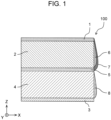
- FIG. 1 is a schematic view showing a cross section of all-solid battery 100 in the present embodiment.
- all-solid battery 100 according to the present embodiment is formed by laminating positive-electrode current collector 1, positive-electrode layer 2 containing a positive-electrode active material, solid electrolyte layer 5 containing a solid electrolyte, negative-electrode layer 4 containing a negative-electrode active material, and negative-electrode current collector 3 in this order.
- positive-electrode fine particle layer 6 containing positive-electrode active material fine particles having a particle diameter smaller than that of the positive-electrode active material is formed.
- negative-electrode fine particle layer 8 containing negative-electrode active material fine particles having a particle diameter smaller than that of the negative-electrode active material is formed.
- solid electrolyte fine particle layer 7 may be formed on the outside of positive-electrode fine particle layer 6, solid electrolyte layer 5, and positive-electrode layer 2.
- all-solid battery 100 in the present embodiment includes positive-electrode current collector 1, positive-electrode layer 2, negative-electrode current collector 3, negative-electrode layer 4, solid electrolyte layer 5, positive-electrode fine particle layer 6, solid electrolyte fine particle layer 7, and negative-electrode fine particle layer 8.
- Positive-electrode current collector 1 is made of metal foil or the like.
- Positive-electrode layer 2 contains a positive-electrode active material and is formed on positive-electrode current collector 1.
- Negative-electrode current collector 3 is made of metal foil or the like.
- Negative-electrode layer 4 contains a negative-electrode active material and is formed on negative-electrode current collector 3.
- Solid electrolyte layer 5 includes a solid electrolyte having at least ion conductivity and is disposed between positive-electrode layer 2 and negative-electrode layer 4.
- Positive-electrode fine particle layer 6 contains fine particles of the material contained in positive-electrode layer 2.
- Solid electrolyte fine particle layer 7 contains fine particles of the material contained in solid electrolyte layer 5.
- Negative-electrode fine particle layer 8 contains fine particles of the material contained in negative-electrode layer 4.
- positive-electrode current collector 1 is an example of a first current collector
- negative-electrode current collector 3 is an example of a second current collector.
- the "particle diameter" in the present specification is a volume-based average particle diameter measured by a laser analysis and scattering particle density distribution measuring device.
- All-solid battery 100 may contain a slight amount of a binder that causes at least one of the positive-electrode active material and positive-electrode current collector 1, the positive-electrode active material and solid electrolyte layer 5, the positive-electrode active materials (particles constituting the positive-electrode active material), the negative-electrode active material and negative-electrode current collector 3, the negative-electrode active material and solid electrolyte layer 5, the negative-electrode active materials (particles constituting the negative-electrode active material), and solid electrolyte layers 5 (particles constituting the solid electrolyte) to be in close contact with each other.
- a binder that causes at least one of the positive-electrode active material and positive-electrode current collector 1, the positive-electrode active material and solid electrolyte layer 5, the positive-electrode active materials (particles constituting the positive-electrode active material), the negative-electrode
- Positive-electrode fine particle layer 6 may be formed in contact with the side surface of positive-electrode layer 2, and a part of positive-electrode fine particle layer 6 may cover the side surface of positive-electrode current collector 1.
- Positive-electrode fine particle layer 6 contains a material of the same component as that of positive-electrode layer 2.
- the particle diameter of the fine particles of a plurality of materials contained in positive-electrode fine particle layer 6 is smaller than the particle diameter of the particles of the material of the same component contained in positive-electrode layer 2 respectively.
- the particle diameter of the positive-electrode active material fine particles contained in positive-electrode fine particle layer 6 is smaller than the particle diameter of the particles of the positive-electrode active material contained in positive-electrode layer 2.
- Solid electrolyte fine particle layer 7 is formed so as to cover the outside solid electrolyte layer 5, positive-electrode layer 2, and positive-electrode fine particle layer 6 in plan view, and a part of solid electrolyte fine particle layer 7 is a side surface of positive-electrode current collector 1.
- Solid electrolyte fine particle layer 7 contains a material of the same component as that of solid electrolyte layer 5.
- the particle diameter of the fine particles of a plurality of materials contained in solid electrolyte particle layer 7 is smaller than the particle diameter of the fine particles of the material of the same component contained in solid electrolyte layer 5 respectively.
- the particle diameter of the solid electrolyte fine particles contained in solid electrolyte fine particle layer 7 is smaller than the particle diameter of the solid electrolyte particles contained in solid electrolyte layer 5.
- Negative-electrode fine particle layer 8 may be formed in contact with the side surface of negative-electrode layer 4, and a part of negative-electrode fine particle layer 8 may cover the side surface of negative-electrode current collector 3.
- Negative-electrode fine particle layer 8 contains a material of the same component as that of negative-electrode layer 4.
- the particle diameter of the fine particles of a plurality of materials contained in negative-electrode fine particle layer 8 is smaller than the particle diameter of the particles of the material of the same component contained in negative-electrode layer 4 respectively.
- the particle diameter of the negative-electrode active material fine particles contained in negative-electrode fine particle layer 8 is smaller than the particle diameter of the particles of the negative-electrode active material contained in negative-electrode layer 4.
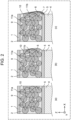
- FIG. 2 is a schematic view showing the vicinity of the side surface of positive-electrode layer 2 in all-solid battery 100. Since FIG. 2 is a schematic view for describing the details of positive-electrode fine particle layer 6 and solid electrolyte fine particle layer 7, each component may differ from an actual shape, a positional relationship, and a dimensional ratio. In addition, in FIG. 2 , positive-electrode mixture materials other than the positive-electrode active material particles contained in positive-electrode layer 2 are omitted.
- Electron conduction path 11a indicates the flow of current (that is, the direction opposite to the flow of electrons) with an arrow. Electrons flow through the point at which positive-electrode active material particles 9 are in contact with each other. Although not illustrated, in a case where a conductive assistant is contained, electrons pass through the contact point between positive-electrode active material particle 9 and the conductive assistant and the contact point between the conductive assistants. However, since positive-electrode active material particles 9 are cut at side surface 10 of positive-electrode layer 2, the electron conduction path is broken, and the number of electron conduction paths 11a that can be formed is reduced.
- FIG. 2 is a view showing a case where positive-electrode fine particle layer 6 is formed on side surface 10 of positive-electrode layer 2. Since positive-electrode fine particle layer 6 contains a positive-electrode active material to be an electron conduction path, positive-electrode fine particle layer 6 is formed, whereby electron conduction path 11b passing through positive-electrode fine particle layer 6 is newly formed. As a result, the electron conduction efficiency in positive-electrode layer 2 is improved, and the battery capacity of all-solid battery 100 is improved. Although not shown, in a case where positive-electrode layer 2 contains a solid electrolyte, positive-electrode fine particle layer 6 contains fine particles of the solid electrolyte.
- positive-electrode fine particle layer 6 increases the number of ion conduction paths through the fine particles of the solid electrolyte contained in positive-electrode fine particle layer 6 as well as electron conduction path 11b. Thereby, the ion conductivity of lithium ions in positive-electrode layer 2 is improved, and the battery capacity of all-solid battery 100 is improved.
- the region is formed at least in a range of the distance between positive-electrode active material particles 9 or the distance between the solid electrolyte particles. Furthermore, it is more desirable that the length of the plane where positive-electrode fine particle layer 6 and positive-electrode layer 2 are in contact with each other in the laminating direction is at least twice the particle diameter of the positive-electrode active material.
- the length of the plane where positive-electrode fine particle layer 6 and positive-electrode layer 2 are in contact with each other in the laminating direction is 20 ⁇ m or more.
- negative-electrode fine particle layer 8 is also similar to positive-electrode fine particle layer 6, and the same effect can be obtained.
- FIG. 2 is a view showing a case where positive-electrode fine particle layer 6 is formed on side surface 10 of positive-electrode layer 2 and solid electrolyte fine particle layer 7 is formed on the outside of positive-electrode fine particle layer 6.
- the contact between positive-electrode fine particle layer 6 and negative-electrode layer 4 or negative-electrode current collector 3 can be suppressed, and the risk of a short circuit can be reduced by forming thin solid electrolyte fine particle layer 7 containing the solid electrolyte fine particles having insulation performance on the outside of positive-electrode fine particle layer 6.
- solid electrolyte fine particle layer 7 As a range in which solid electrolyte fine particle layer 7 is formed, a part of positive-electrode fine particle layer 6 may be covered. Furthermore, as shown in (c) of FIG. 2 , it is preferable that solid electrolyte fine particle layer 7 be formed so as to cover the entire outer surface of positive-electrode fine particle layer 6. In (c) of FIG. 2 , positive-electrode fine particle layer 6 is formed so as to cover entire side surface 10 of positive-electrode layer 2, but in a case where there is a region where positive-electrode fine particle layer 6 is not formed on side surface 10 of positive-electrode layer 2, solid electrolyte fine particle layer 7 may be formed on side surface 10 of positive-electrode layer 2.
- FIG. 3 is a top view which shows all-solid battery 200 before the laser cutting step to be described later, that is, after a pressing step.
- (b) of FIG. 3 is a cross-sectional view showing a cross section of all-solid battery 200 taken along the line D-D shown in (a) of FIG. 3 .
- the plane in top view is the X-Y plane in FIG. 3 .
- region W which does not function as a battery is generated between end portion 51 which is the outermost portion of positive-electrode current collector 1 and negative-electrode current collector 3, and end portion 52 which is the outermost portion of positive-electrode layer 2, in relation to end portion 52 of positive-electrode layer, end portion 54 of negative-electrode layer, end portion 55 of solid electrolyte layer, and end portion 51 of positive-electrode current collector and negative-electrode current collector.
- all-solid battery 100 in the present embodiment shown in FIG. 1 has a shape in which region W is reduced by making region W slightly larger than the size in which all-solid battery 200 before the laser cutting step is housed in the case and cutting region W with a laser beam.
- the size of all-solid battery 200 is 200 ⁇ 100 mm and region W is reduced from 2.5 mm to 0.1 mm, the volume functioning as a battery, that is, the capacity of the battery can be increased by about 7.6%.
- solid electrolyte layer 5 in the present embodiment includes a solid electrolyte and a binder.
- a binder for example, a binding binder such as a thermoplastic elastomer, a polyvinylidene fluoride, or the like in which a functional group for improving adhesive strength is introduced is used.
- the binder is preferably a binder that has a functional group that enhances adhesive strength by reacting with and binding to the solid electrolyte, and that achieves high adhesive strength between the solid electrolytes.
- Solid electrolyte layer 5 may not contain a binder.
- the solid electrolyte in the present embodiment will be described.
- the solid electrolyte can be roughly divided into a sulfide-based solid electrolyte and an oxide-based solid electrolyte, and a sulfide-based solid electrolyte may be used or an oxide-based solid electrolyte may be used.
- the type of the sulfide-based solid electrolyte in the present embodiment is not particularly limited, but Li 2 S-SiS 2 , LiI-Li 2 S-SiS 2 , LiI-Li 2 S-P 2 S 5 , LiI-Li 2 S-P 2 O 5 , LiI-Li 3 PO 4 -P 2 S 5 , Li 2 S-P 2 S 5 , and the like can be mentioned, for example.
- the sulfide-based solid electrolyte contains Li, P, and S because the ion conductivity of lithium is excellent.
- the sulfide-based solid electrolyte may be used alone or in combination of two or more.
- sulfide-based solid electrolyte containing P 2 S 5 is preferably used because the reactivity between P 2 S 5 and the binder is high and the bonding property with the binder is high.
- the description of "Li 2 S-P 2 S 5 " means a sulfide-based solid electrolyte formed using a raw material composition containing Li 2 S and P 2 S 5 , and the same applies to other descriptions.
- the sulfide-based solid electrolyte material is, for example, a sulfide-based glass ceramic containing Li 2 S and P 2 S 5
- the ratio of Li 2 S and P 2 S 5 is preferably in the range of 70:30 or more and 80:20 or less, and more preferably in the range of 75:25 or more and 80:20 or less in terms of molar conversion of Li 2 S: P 2 S 5 .
- the reason why the ratio of Li 2 S to P 2 S 5 within the above range is preferable is that the crystal structure is high in ion conductivity while maintaining the Li concentration that affects the battery characteristics, and another reason is that the amount of P 2 S 5 for reacting with and binding to the binder is secured.
- the oxide-based solid electrolyte in the present embodiment will be described.
- the type of the oxide-based solid electrolyte is not particularly limited, but LiPON, Li 3 PO 4 , Li 2 SiO 2 , Li 2 SiO 4 , Li 0.5 La 0.5 TiO 3 , Li 1.3 Al 0.3 Ti 0.7 (PO 4 ) 3 , La 0.51 Li 0.34 TiO 0.74 , Li 1.3 Al 0.5 Ge 1.4 (PO 4 ) 3 and the like can be mentioned.
- the oxide-based solid electrolyte may be used alone or in combination of two or more.
- Examples of the shape of the positive-electrode active material include a spherical shape, an oval spherical shape, a cubic shape, a prismatic shape, a columnar shape, a needle shape, a scaly shape, and a shape in which these shapes are irregularly combined.
- the average particle diameter (D 50 ) of the solid electrolyte is not particularly limited, but is preferably 10 ⁇ m or less because it is easy to improve the density in the layer.
- the binder in the present embodiment will be described.
- a functional group for improving the adhesive strength is introduced, and the functional group reacts with the solid electrolyte, bonds the solid electrolytes via the binder, and forms a structure in which the binder is disposed between the solid electrolyte and the solid electrolyte.
- the adhesive strength between the solid electrolytes is improved.
- the addition amount of the binder in the present embodiment is, for example, preferably in the range of 0.001% by mass or more and 5% by mass or less, more preferably in the range of 0.01% by mass or more and 3% by mass or less, and further more preferably in the range of 0.01% by mass or more and 1% by mass or less.
- the addition amount of the binder to 5% by mass or less, deterioration of the battery characteristics such as charge and discharge characteristics does not easily occur, and further, for example, in a low-temperature region, even if physical property values such as the hardness, tensile strength, and tensile elongation of the binder change, the charge and discharge characteristics are hardly deteriorated.
- Positive-electrode layer 2 in the present embodiment contains a solid electrolyte, a positive-electrode active material, and a binder. Positive-electrode layer 2 may not contain a binder. In a case where positive-electrode layer 2 contains a binder, for example, the positive-electrode active material and the solid electrolyte, the positive-electrode active material and positive-electrode current collector 1, the solid electrolyte and positive-electrode current collector 1, the positive-electrode active materials, and the solid electrolytes adhere to each other through the binder having a functional group introduced therein to improve adhesive strength.
- the ratio of the solid electrolyte to the positive-electrode active material is preferably in the range of 50:50 or more and 5:95 or less, and more preferably 30:70 or more and 10:90 in terms of weight conversion of solid electrolyte: positive-electrode active material.
- the reason for being preferably in the above range is that both the lithium ion conduction path and the electron conduction path in positive-electrode layer 2 can be easily secured.
- a conductive assistant such as acetylene black or ketjen black may be added to positive-electrode layer 2.
- Positive-electrode current collector 1 is made of metal foil or the like, and as a metal of the metal foil, for example, SUS, aluminum, nickel, titanium, copper or the like is used.
- the binder is the same as the binder described above, the description is omitted.
- the positive-electrode active material in the present embodiment will be described.
- a lithium-containing transition metal oxide is used as the positive-electrode active material in the present embodiment.
- the lithium-containing transition metal oxide include LiCoO 2 , LiNiO 2 , LiMn 2 O 4 , LiCoPO 4 , LiNiPO 4 , LiFePO 4 , LiMnPO 4 , and compounds obtained by substituting the transition metal of these compounds with one or two different elements.
- Examples of the compound obtained by substituting the transition metal of the above-described compounds with one or two different elements include known materials such as LiNi 1/3 Co 1/3 Mn 1/3 O 2 , LiNi 0.8 Co 0.15 Al 0.05 O 2 , LiNi 0.5 Mn 1.5 O 2 and the like.
- the positive-electrode active material may be used alone or in combination of two or more.
- Examples of the shape of the positive-electrode active material include a spherical shape, an oval spherical shape, a cubic shape, a prismatic shape, a columnar shape, a needle shape, a scaly shape, and a shape in which these shapes are irregularly combined.
- the average particle diameter (D 50 ) of the positive-electrode active material is, for example, preferably in the range of 50 nm to 50 ⁇ m inclusive, and more preferably in the range of 1 ⁇ m to 15 ⁇ m inclusive.
- the average particle diameter of the positive-electrode active material is 50 nm or more, the handling property is easily improved.
- the average particle diameter is 50 ⁇ m or less, a flat positive-electrode layer is easily obtained, and therefore the above range is preferable.
- Negative-electrode layer 4 in the present embodiment contains a solid electrolyte, a negative-electrode active material, and a binder. Negative-electrode layer 4 may not contain a binder. In a case where negative-electrode layer 4 contains a binder, for example, the negative-electrode active material and the solid electrolyte, the negative-electrode active material and negative-electrode current collector 3, the solid electrolyte and negative-electrode current collector 3, the negative-electrode active materials, and the solid electrolytes adhere to each other through the binder having a functional group introduced therein to improve adhesive strength.
- the ratio of the solid electrolyte to the negative-electrode active material is preferably in the range of 5:95 or more and 60:40 or less, and more preferably 30:70 or more and 50:50 or less in terms of weight conversion of solid electrolyte: negative-electrode active material.
- the reason for being preferably in the above range is that both the lithium ion conduction path and the electron conduction path in negative-electrode layer 4 can be easily secured.
- a conductive assistant such as acetylene black and ketjen black may be added to negative-electrode layer 4.
- Negative-electrode current collector 3 is made of metal foil or the like, and as the metal of the metal foil, for example, SUS, copper, nickel or the like is used.
- the binder is the same as the binder described above, the description is omitted.
- the negative-electrode active material in the present embodiment will be described.
- metal foil made of a metal that forms an alloy with lithium such as lithium, indium, tin, and silicon, hard carbon, carbon materials such as graphite, or known materials such as Li 4 Ti 5 O 12 and SiOx may be used.
- Examples of the shape of the negative-electrode active material include a spherical shape, an oval spherical shape, a cubic shape, a prismatic shape, a columnar shape, a needle shape, a scaly shape, and a shape in which these shapes are irregularly combined.
- the average particle diameter (D 50 ) of the negative-electrode active material is, for example, preferably in the range of 50 nm to 50 ⁇ m inclusive, and more preferably in the range of 1 ⁇ m to 15 ⁇ m inclusive.
- the average particle diameter of the negative-electrode active material is 50 nm or more, the handling property is easily improved.
- the average particle diameter is 50 ⁇ m or less, a flat negative-electrode layer is easily obtained, and therefore the above range is preferable.
- the method of manufacturing all-solid battery 100 shown in FIG. 1 includes a laminate forming step (not shown) and a laser cutting step.
- the laminate forming step is a step of forming a laminated structure in which positive-electrode current collector 1, positive-electrode layer 2, solid electrolyte layer 5, negative-electrode layer 4, and negative-electrode current collector 3 are laminated in this order.
- the laser cutting step is a step of cutting the laminated structure with a laser beam, solidifying the vapor (material vapor) from the laminated structure generated at the time of cutting, and depositing the solidified material on the side surface of positive-electrode layer 2 and the side surface of negative-electrode layer 4.
- the manufacturing method of all-solid battery 100 may include a laminate forming step (not shown), a pressing step (not shown), and a laser cutting step.
- the laminate forming step is a step of forming a laminated structure in which positive-electrode current collector 1, positive-electrode layer 2, solid electrolyte layer 5, negative-electrode layer 4, and negative-electrode current collector 3 are laminated in this order by film formation such as coating step.
- the pressing step is a step of compressing the laminated structure in order to adjust the filling ratio of each layer to a predetermined filling ratio for solid electrolyte layer 5, positive-electrode layer 2, and negative-electrode layer 4 formed in the laminate forming step.
- the laser cutting step is a step of cutting the laminated structure with a laser beam, solidifying the material vapor generated at the time of cutting, and depositing the solidified material on the side surface of positive-electrode layer 2 and the side surface of negative-electrode layer 4.
- a laminated structure is obtained by forming and laminating positive-electrode layer 2 including the positive-electrode active material formed on positive-electrode current collector 1 made of metal foil or the like, negative-electrode layer 4 including the negative-electrode active material formed on negative-electrode current collector 3 made of metal foil or the like, and solid electrolyte layer 5 containing the solid electrolyte having ion conductivity, disposed between positive-electrode layer 2 and negative-electrode layer 4, respectively.
- a known method can be used such as a method of forming each layer by forming a film by applying a slurry material to a substrate or the like and laminating the formed layers.
- a known method such as a method of forming each layer by forming a film by applying a slurry material to a substrate or the like and laminating the formed layers.
- the above-described non-functional region is likely to be formed because the dimensional accuracy at the time of coating is low.
- the laminate formed in the laminate forming step is pressurized from the outside of positive-electrode current collector 1 and negative-electrode current collector 3, and all-solid battery 200 before the laser cutting step, which is a compressed laminated structure, is obtained.
- the filling ratio of at least one layer of solid electrolyte layer 5, positive-electrode layer 2, and negative-electrode layer 4 becomes 60% or more and less than 100%, and in at least one layer in solid electrolyte layer 5, positive-electrode layer 2, and negative-electrode layer 4, the number of voids is reduced.
- the filling ratio is the ratio of the volume occupied by the material excluding the voids in the total volume of each layer.
- the laser cutting step is a step of cutting the laminated structure with a laser beam, solidifying the vapor from the laminated structure generated at the time of cutting, and depositing the solidified material on the side surface of positive-electrode layer 2 and the side surface of negative-electrode layer 4.
- the solidified material is brought into contact with the side surface of the positive-electrode layer 2 to form positive-electrode fine particle layer 6 containing positive-electrode active material fine particles having a particle diameter smaller than that of the positive-electrode active material.
- the solidified material is brought into contact with the side surface of negative-electrode layer 4 to form negative-electrode fine particle layer 8 containing negative-electrode active material fine particles having a particle diameter smaller than that of the negative-electrode active material.
- the material vapor may be solidified by blowing a gas, and the solidified material may be deposited.
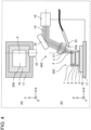
- FIG. 4 is a schematic view of laser processing apparatus 400 in the manufacturing method according to the present embodiment.
- FIG. 4 shows a state in which all-solid battery 200 before the laser cutting step is fixed to laser processing apparatus 400.
- (a) of FIG. 4 is a top view of laser processing apparatus 400 and all-solid battery 200
- (b) of FIG. 4 is a cross-sectional view of laser processing apparatus 400 and all-solid battery 200.
- Laser processing apparatus 400 includes fixed table 16, drive stage 17, laser oscillator 18 that emits laser beam 19, mirror 20, lens 21, blower 22, and dust collector 23. In (a) of FIG. 4 , components other than fixed table 16, drive stage 17, dust collector 23, and all-solid battery 200 are omitted.
- Fixed table 16 fixes all-solid battery 200 thereon by, for example, vacuum suction. As fixed table 16, one that does not cause positional deviation of all-solid battery 200 due to driving by drive stage 17 described later is used.
- Drive stage 17 can drive fixed table 16 installed on drive stage 17 in the three axial directions of XYZ and controls the relative position of the laser beam with respect to all-solid battery 200 fixed to fixed table 16.
- Laser oscillator 18 emits laser beam 19 having a maximum repetition frequency of 1 MHz which is a picosecond laser having a wavelength at which all-solid battery 200 has an absorption rate of 10% or more, for example, a wavelength of 1064 nm, a pulse width of 50 ps or less, and a maximum output of 100 W.
- laser oscillator 18 desirably uses an ultrashort pulse laser having a pulse width of 50 ps or less in order to suppress the change in quality due to heat at the time of cutting and deterioration of the processed shape.
- laser oscillator 18 can perform ON/OFF control of the laser beam by exchanging a control signal with drive stage 17.
- Laser beam 19 is a laser beam emitted from laser oscillator 18 and is a linearly polarized laser beam.
- Mirror 20 is a mirror that can reflect laser beam 19 emitted from laser oscillator 18 by 90% or more and transmit the laser beam to the processing location, and can adjust irradiation angle ⁇ of laser beam 19 to all-solid battery 200.
- mirror 20 in the present embodiment for example, a dielectric multilayer mirror that reflects a wavelength of 1064 nm is used.
- Lens 21 condenses parallel laser beam 19 so that laser beam 19 is concentrated at the processing location of all-solid battery 200, and as lens 11 in the present embodiment, a lens with a focal length of 40 mm that transmits a wavelength of 1064 nm by 50% or more is used.
- Blower 22 is for blowing the gas emitted from blowing portion 22a to the material vapor generated at processing point F and can move blowing portion 22a.
- the gas blown by blower 22 is not particularly limited as long as the gas does not deteriorate the material used for the all-solid battery and is, for example, an inert gas such as argon. Nitrogen gas, dry air, and air may be used in the range which does not deteriorate a positive-electrode active material, a negative-electrode active material, and a solid electrolyte as a gas to blow.
- Dust collector 23 is a suction machine for suctioning dust generated at processing point F. Dust collector 23 may be fixed or movable.
- FIG. 5 is a schematic view showing a cutting method by laser processing of all-solid battery 200 before the laser cutting step, and the laser cutting step of the manufacturing method of the all-solid battery in the present embodiment will be described below.
- FIG. 5 shows only the cross section of all-solid battery 200 and laser beam 19, and the other components of laser processing apparatus 400 are omitted.
- the views on the left side of the arrows are the views when all-solid battery 200 is irradiated with laser beam 19.
- the views on the right of the arrows show the state of all-solid battery 200 after being irradiated with laser beam 19.
- laser beam 19 is focused on the uppermost surface of positive-electrode current collector 1 and laser beam 19 is scanned in the direction (Y-axis direction) perpendicular to the drawing to form a linear groove in the Y-axis direction.
- the focal point of laser beam 19 is moved in the X-axis direction, and scanning of laser beam 19 in the direction (Y-axis direction) perpendicular to the drawing is repeated to perform removal processing while connecting linear grooves in the Y-axis direction in the X-axis direction.
- planar removal portion 24a is formed in positive-electrode current collector 1, and positive-electrode layer 2 is exposed.
- vapor component 25a generated by sublimation of the material when removing positive-electrode current collector 1 is removed ((a) of FIG. 5 ).
- laser beam 19 is focused on exposed positive-electrode layer 2 and laser beam 19 is scanned in the direction (Y-axis direction) perpendicular to the drawing to form a linear groove in the Y-axis direction. Then, the focal point of laser beam 19 is moved in the X-axis direction, and scanning of laser beam 19 in the direction (Y-axis direction) perpendicular to the drawing is repeated to perform removal processing while connecting the linear grooves in the Y-axis direction in the X-axis direction and form a removal portion in the form of an elongated surface in the Y-axis direction in positive-electrode layer 2 and solid electrolyte layer 5.
- removal processing is performed while moving the focal position of laser beam 19 in the depth direction, and a removal portion in the form of an elongated surface elongated in the Y-axis direction is superimposed.
- removal portion 24b is formed which extends over the entire positive-electrode layer 2 (the lower surface of positive-electrode layer 2) in the thickness direction.
- blower 22 (see (b) of FIG. 4 ) is operated, a gas is blown toward side surface 10 of positive-electrode layer 2 from blowing portion 22a of blower 22 to cool vapor component 25b of the positive-electrode mixture material generated by the sublimation of the material when removing positive-electrode layer 2.
- Vapor component 25b is a positive-electrode material mixture material which is sublimed and removed by a short pulse laser and becomes very fine particles by being cooled.
- vapor component 25d of negative-electrode mixture material is cooled and precipitated as fine particles, and negative-electrode fine particle layer 8 is formed on the outside of negative-electrode layer 4 in plan view.
- dust collector 23 removes vapor component 25e of negative-electrode current collector 3.
- the fine particles of the negative-electrode current collector material do not form a layer on the outside of positive-electrode fine particle layer 6 at least in plan view.
- the state shown by (e) of FIG. 5 is the state in which the cutting in the thickness direction of each layer is completed.
- the reason is that the density of the vapor component is higher near the processing point and it is easy to precipitate the vapor component when removing and processing the lower side of positive-electrode layer 2 and further, the outer peripheral portion of laser beam 19 may hit fine particles precipitated on the upper side of side surface 10 of positive-electrode layer 2 and cause some of the fine particles to evaporate.
- FIG. 5 shows an example in which removal processing is performed by using laser beam 19.
- another laser beam different from laser beam 19 may be further used as the laser beam used for the removal processing.
- a laser beam emitted from a solid-state laser having a wavelength of 355 nm, a pulse width of 40 ns, and a frequency of 500 kHz and collected by a lens having a focal length of 100 mm may be used as another laser beam.
- Such a laser beam has a large pulse width and therefore has a large removal amount compared to laser beam 19 but has a feature that the dimensional accuracy is low and the thermal influence is also large.
- a plurality of all-solid batteries 200 may be laminated, and the plurality of laminated all-solid batteries 200 may be simultaneously cut by using a laser.
- a laser beam multi-branched in the XYZ axis direction by a diffractive optical element or the like may be used so that the removal portion by laser beam 19 is continuous.
- laser beam 19 is irradiated from positive-electrode current collector 1 side
- laser beam 19 may be irradiated from negative-electrode current collector 3 side.
- solid electrolyte fine particle layer 7 is formed on the outside of negative-electrode fine particle layer 8.
- blower 22 was used as a method of precipitating and depositing the vapor component of the evaporated material.
- a part of the evaporated material may be precipitated on the side surfaces of positive-electrode layer 2 and negative-electrode layer 4 by adjusting the conditions of dust collector 23.
- a structure in which positive-electrode layer 2, negative-electrode layer 4, and solid electrolyte layer 5 are sandwiched between positive-electrode current collector 1 and negative-electrode current collector 3 is used.
- the present disclosure is not limited to this structure. It is also possible to use a structure in which negative-electrode layer 4 and solid electrolyte layer 5 are formed on the lower surface side (upper surface side) opposite to the surface on which positive-electrode layer 2, solid electrolyte layer 5, and positive-electrode layer 2 are formed on the upper surface side (lower surface side) of the current collector with the current collector interposed therebetween.
- all-solid battery 100 shown in FIG. 1 is obtained.
- a terminal is attached to the obtained all-solid battery 100 and stored in a case.
- a case of all-solid battery 100 for example, a case made of an aluminum laminated bag, SUS, iron, aluminum, or resin is used.
- EXEMPLARY EMBODIMENT 2 will be described below. In the following description, differences from the above-described EXEMPLARY EMBODIMENT 1 will be mainly described, and the description of the common points will be appropriately omitted or simplified.
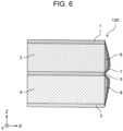
- FIG. 6 is a schematic view showing a cross section of all-solid battery 120 in EXEMPLARY EMBODIMENT 2.
- all-solid battery 120 according to the present embodiment is formed by laminating positive-electrode current collector 1, positive-electrode layer 2 containing a positive-electrode active material, solid electrolyte layer 5 containing a solid electrolyte, negative-electrode layer 4 containing a negative-electrode active material, and negative-electrode current collector 3 in this order.
- positive-electrode fine particle layer 6 may be formed in contact with the side surface of positive-electrode layer 2, and a part of positive-electrode fine particle layer 6 may cover the side surface of positive-electrode current collector 1.
- the particle diameter of the fine particles of a plurality of materials contained in positive-electrode fine particle layer 6 is smaller than the particle diameter of the particles of the material of the same component contained in positive-electrode layer 2 respectively.
- Negative-electrode fine particle layer 8 may be formed on the side surface of negative-electrode layer 4, and a part of negative-electrode fine particle layer 8 may cover the side surface of negative-electrode current collector 3.
- the particle diameter of the fine particles of a plurality of materials contained in negative-electrode fine particle layer 8 is smaller than the particle diameter of the particles of the material of the same component contained in negative-electrode layer 4 respectively.
- Solid electrolyte fine particle layer 7 is formed to cover the outside of positive-electrode layer 2, positive-electrode fine particle layer 6, solid electrolyte layer 5, negative-electrode layer 4, and negative-electrode fine particle layer 8 in plan view.
- a part of solid electrolyte fine particle layer 7 may cover the side surface of positive-electrode current collector 1 and the side surface of negative-electrode current collector 3.
- the particle diameter of the fine particles of a plurality of materials contained in solid electrolyte fine particle layer 7 is smaller than the particle diameter of the particles of the material of the same component contained in solid electrolyte layer 5 respectively.
- the manufacturing method of the all-solid battery in EXEMPLARY EMBODIMENT 2 is described.
- the manufacturing method of the all-solid battery according to EXEMPLARY EMBODIMENT 2 is the same as that of EXEMPLARY EMBODIMENT 1 except the processing method in the laser cutting step, and therefore, the laser cutting step will be mainly described.
- FIG. 7 is a schematic view showing laser processing apparatus 410 used in the manufacturing method of the all-solid battery according to EXEMPLARY EMBODIMENT 2.
- FIG. 7 shows a state in which all-solid battery 200 before the laser cutting step is fixed to laser processing apparatus 410.
- (a) of FIG. 7 is a top view of laser processing apparatus 410 and all-solid battery 200.
- (b) of FIG. 7 is a cross-sectional view of laser processing apparatus 410 and all-solid battery 200.
- Laser processing apparatus 410 includes fixed table 16, drive stage 17, laser oscillator 18 that emits laser beam 19, mirror 20, lens 21, blower 22, dust collector 23, half mirror 29, folding mirror 30, and processing portion 32.
- components other than fixed table 16, drive stage 17, dust collector 23, processing portion 32, and all-solid battery 200 are omitted.
- Half mirror 29 divides the laser beam into laser beam 19 irradiated to positive-electrode layer 2 side and laser beam 31 irradiated to negative-electrode layer 4 side by a power distribution of 1: 1.
- Folding mirror 30 is a mirror that has a reflectance of 90% or more and can determine the propagation path of laser beam 31.
- Laser beam 19 is reflected by folding mirror 30 and mirror 20 and is transmitted to the processing location on negative-electrode layer 4 side of all-solid battery 200.
- Processing portion 32 is a hole provided in fixed table 16 and drive stage 17 along the planned processing shape of the all-solid battery and is formed so as not to block laser beam 31. Processing portion 32 allows laser beam 31 to pass through fixed table 16 and drive stage 17, and the gas ejected from blower 22 can reach processing point F with almost no loss.
- laser processing apparatus 410 Since laser beam 19 and the laser beam 31 are irradiated to the all-solid battery 200 in laser processing apparatus 410, laser processing apparatus 410 is provided with two mirrors 20, two lenses 21, and two blowers 22.
- FIG. 8 shows only the cross section of all-solid battery 200, laser beam 19, and laser beam 31, and other components of the laser processing apparatus 410 are omitted.
- the views on the left side of the arrows are the views when all-solid battery 200 is irradiated with laser beam 19 and laser beam 31.
- the views on the right side of the arrows show the state of all-solid battery 200 after being irradiated with laser beam 19 and laser beam 31.
- laser beam 19 is focused on the uppermost surface of positive-electrode current collector 1 and laser beam 19 is scanned in the direction (Y-axis direction) perpendicular to the drawing to form a linear groove in the Y-axis direction. Then, the focal point of laser beam 19 is moved in the X-axis direction, and scanning of laser beam 19 in the direction (Y-axis direction) perpendicular to the drawing is repeated to perform removal processing while connecting linear grooves in the Y-axis direction in the X-axis direction.
- removal portion 24a in the form of an elongated surface in the Y-axis direction is formed on positive-electrode current collector 1, and positive-electrode layer 2 is exposed.
- vapor component 25a generated by sublimation of the material when removing positive-electrode current collector 1 is removed.
- negative-electrode current collector 3 The removal of negative-electrode current collector 3 is the same operation as that of positive-electrode current collector 1, but laser beam 31 is irradiated from the opposite side of positive-electrode current collector 1, and laser beam 31 is focused on the uppermost surface of negative-electrode current collector 3, and removal portion 24e in the form of an elongated surface in the Y-axis direction is formed on negative-electrode current collector 3.
- removal portion 24e vapor component 25e of negative-electrode current collector is removed by dust collector 23.
- laser beam 19 is focused on the exposed positive-electrode layer 2, and laser beam 19 is scanned in the direction (Y-axis direction) perpendicular to the drawing to form a linear groove in the Y-axis direction. Then, the focal point of laser beam 19 is moved in the X-axis direction, and scanning of laser beam 19 in the direction (Y-axis direction) perpendicular to the drawing is repeated to perform removal processing while connecting linear grooves in the Y-axis direction in the X-axis direction. As a result, a removal portion in the form of an elongated surface in the Y-axis direction is formed in positive-electrode layer 2 and solid electrolyte layer 5.
- removal processing is performed while moving the focal position of laser beam 19 in the depth direction, and removal portion 24b is formed which extends over the entire positive-electrode layer 2 (the lower surface of positive-electrode layer 2) in the thickness direction by superimposing the removal portion in the form of an elongated surface in the Y-axis direction.
- blower 22 is operated, a gas is blown toward the end portion of positive-electrode layer 2 from blowing portion 22a of blower 22 to cool vapor component 25b of the positive-electrode mixture material generated by the sublimation of the material when removing positive-electrode layer 2.
- Vapor component 25b is a positive-electrode material mixture material which is sublimed and removed by a short pulse laser and becomes very fine particles by being cooled.
- negative-electrode layer 4 is the same as that of positive-electrode layer 2 except that laser beam 31 is irradiated from the opposite side of positive-electrode layer 2 to focus laser beam 31 on the exposed negative-electrode layer 4.
- removal portion 24d is formed which extends over the entire negative-electrode layer 4 (the upper surface of negative-electrode layer 4) in the thickness direction by superimposing the removal portion in the form of an elongated surface in the Y-axis direction.
- vapor component 25d of the negative-electrode mixture material is cooled by blowing the gas by blowing a gas toward side surface 12 of negative-electrode layer 4 from blowing portion 22a of blower 22.
- vapor component 25d is precipitated as fine particles on side surface 12 of negative-electrode layer 4, and negative-electrode fine particle layer 8 is formed on the outside of side surface 12 of negative-electrode layer 4.
- removal portion 24c As shown in (c) of FIG. 8 , with respect to solid electrolyte layer 5, the removal is carried out in the same manner as described above with reference to both positive-electrode layer 2 side and negative-electrode layer 4 side to the center of solid electrolyte layer 5 in the thickness direction to form removal portion 24c.
- a gas is blown toward side surface 10 of positive-electrode layer 2 and side surface 12 of negative-electrode layer 4 from blowing portion 22a of blower 22. Then, vapor component 25c of the solid electrolyte layer material is precipitated on the outside of positive-electrode fine particle layer 6 and negative-electrode fine particle layer 8 to form solid electrolyte fine particle layer 7.
- another laser beam different from laser beam 19 and laser beam 31 may be combined, and batch removal processing may be performed by using a laser beam multi-branched by a diffractive optical element or the like.
- blower 22 was used, but a part of the evaporated material may be precipitated on the side surfaces of positive-electrode layer 2 and negative-electrode layer 4 by adjusting the conditions of dust collector 23.
- the all-solid battery according to the present disclosure has been described based on a plurality of embodiments, but the present disclosure is not limited to these embodiments. Without departing from the gist of the present disclosure, various modifications made to the embodiments by those skilled in the art or another form constructed by combining some components in the embodiments is also within the scope of the present disclosure.
- a positive-electrode fine particle layer and a negative-electrode fine particle layer are formed on one side surface of a positive-electrode layer and a negative-electrode layer, respectively, but the positive-electrode fine particle layer and the negative-electrode fine particle layer may be formed on two or more side surfaces.
- the all-solid battery before the laser cutting step is fixed to the laser processing apparatus and is processed by the laser beam.
- the method of processing the all-solid battery in the laser cutting step is not limited thereto.
- the all-solid battery may be processed by a roll to roll method.
- an all-solid battery may be processed by a laser beam continuously while rotating a roll, or the roll may be stopped at a constant interval and the all-solid battery may be processed by the laser beam.
- the all-solid battery according to the present disclosure is expected to be applied to power sources such as portable electronic devices and various types of batteries such as vehicle-mounted batteries.
Landscapes
- Chemical & Material Sciences (AREA)
- Engineering & Computer Science (AREA)
- General Chemical & Material Sciences (AREA)
- Chemical Kinetics & Catalysis (AREA)
- Electrochemistry (AREA)
- Manufacturing & Machinery (AREA)
- General Physics & Mathematics (AREA)
- Inorganic Chemistry (AREA)
- Condensed Matter Physics & Semiconductors (AREA)
- Physics & Mathematics (AREA)
- Materials Engineering (AREA)
- Secondary Cells (AREA)
- Battery Electrode And Active Subsutance (AREA)
Claims (10)
- Festkörperbatterie (100), umfassend:einen ersten Stromkollektor (1);eine Positivelektrodenschicht (2), die ein Positivelektroden-Aktivmaterial enthält,eine Festelektrolytschicht (5), die einen Festelektrolyten enthält;eine Negativelektrodenschicht (4), die ein Negativelektroden-Aktivmaterial enthält;einen zweiten Stromkollektor (3);eine Positivelektroden-Feinpartikelschicht (6); undeine Negativelektroden-Feinpartikelschicht (8),wobei der erste Stromkollektor (1), die Positivelektrodenschicht (2), die Festelektrolytschicht (5), die Negativelektrodenschicht (4) und der zweite Stromkollektor (3) in dieser Reihenfolge laminiert sind,die Positivelektroden-Feinpartikelschicht (6) Positivelektroden-Aktivmaterial-Feinpartikel enthält, die einen Partikeldurchmesser aufweisen, der kleiner als ein Partikeldurchmesser von Partikeln des Positivelektroden-Aktivmaterials ist und auf einer Seitenoberfläche der Positivelektrodenschicht (2) gebildet ist, unddie Negativelektroden-Feinpartikelschicht (8) Negativelektroden-Aktivmaterial-Feinpartikel enthält, die einen Partikeldurchmesser aufweisen, der kleiner als ein Partikeldurchmesser von Partikeln des Negativelektroden-Aktivmaterials ist, und auf einer Seitenoberfläche der Negativelektrodenschicht (4) gebildet ist.
- Festkörperbatterie nach Anspruch 1,
wobei eine Festelektrolyt-Feinpartikelschicht (7), die Festelektrolyt-Feinpartikel umfasst, die einen Partikeldurchmesser aufweisen, der kleiner als ein Partikeldurchmesser von Partikeln des Festelektrolyten ist, auf einer Außenseite von mindestens einer von der Positivelektroden-Feinpartikelschicht (6) und der Negativelektroden-Feinpartikelschicht (8) gebildet ist. - Festkörperbatterie nach Anspruch 2,
wobei die Festelektrolyt-Feinpartikelschicht (7) derart gebildet ist, dass sie die Außenseite der Positivelektroden-Feinpartikelschicht (6) bedeckt. - Festkörperbatterie nach Anspruch 2,
wobei die Festelektrolyt-Feinpartikelschicht (7) derart gebildet ist, dass sie die Außenseite der Positivelektroden-Feinpartikelschicht (6) und der Negativelektroden-Feinpartikelschicht (8) bedeckt. - Festkörperbatterie nach einem der Ansprüche 1 bis 4,wobei eine Länge einer Ebene, wo die Positivelektroden-Feinpartikelschicht (6) und die Positivelektrodenschicht (2) miteinander in einer Laminierungsrichtung in Kontakt sind, das Zweifache oder mehr des Partikeldurchmessers des Positivelektroden-Aktivmaterials beträgt, undeine Länge einer Ebene, wo die Negativelektroden-Feinpartikelschicht (8) und die Negativelektrodenschicht (4) miteinander in der Laminierungsrichtung in Kontakt sind, das Zweifache oder mehr des Partikeldurchmessers des Negativelektroden-Aktivmaterials beträgt.
- Verfahren zur Herstellung einer Festkörperbatterie, umfassend:einen Laminierte-Struktur-Bildungsschritt zum Bilden einer laminierten Struktur durch Laminieren eines ersten Stromkollektors (1), einer Positivelektrodenschicht (2), einer Festelektrolytschicht (5), einer Negativelektrodenschicht (4) und eines zweiten Stromkollektors (3) in dieser Reihenfolge; undeinen Laserschneideschritt zum Schneiden der laminierten Struktur mit einem Laserstrahl, Verfestigen von Dampf von der laminierten Struktur, der am Zeitpunkt des Schneidens erzeugt wird, und Abscheiden eines verfestigten Materials auf einer Seitenoberfläche der Positivelektrodenschicht (2) und einer Seitenoberfläche der Negativelektrodenschicht (4),wobei das verfestigte Material mit der Seitenoberfläche der Positivelektrodenschicht (2) in Kontakt gebracht wird, um eine Positivelektroden-Feinpartikelschicht (6) zu bilden, die Positivelektroden-Aktivmaterial-Feinpartikel enthält, die einen Partikeldurchmesser aufweisen, der kleiner als derjenige des Positivelektroden-Aktivmaterials ist, undwobei das verfestigte Material mit der Seitenoberfläche der Negativelektrodenschicht (4) in Kontakt gebracht wird, um eine Negativelektroden-Feinpartikelschicht (8) zu bilden, die Negativelektroden-Aktivmaterial-Feinpartikel enthält, die einen Partikeldurchmesser aufweisen, der kleiner als derjenige des Negativelektroden-Aktivmaterials ist.
- Verfahren zur Herstellung einer Festkörperbatterie nach Anspruch 6,
wobei in dem Laserschneideschritt die laminierte Struktur durch Bestrahlen der laminierten Struktur mit dem Laserstrahl von oben oder unten geschnitten wird. - Verfahren zur Herstellung einer Festkörperbatterie nach Anspruch 6,
wobei in dem Laserschneideschritt die laminierte Struktur durch Bestrahlen der laminierten Struktur mit dem Laserstrahl von oben und unten geschnitten wird. - Verfahren zur Herstellung einer Festkörperbatterie nach einem der Ansprüche 6 bis 8,
wobei in dem Laserschneideschritt ein Gas geblasen wird, um den Dampf von der laminierten Struktur zu verfestigen und ein verfestigtes Material abzuscheiden. - Verfahren zur Herstellung einer Festkörperbatterie nach einem der Ansprüche 6 bis 9,
wobei eine Pulsbreite des Laserstrahls 50 ps oder kürzer beträgt.
Applications Claiming Priority (1)
| Application Number | Priority Date | Filing Date | Title |
|---|---|---|---|
| JP2018246160A JP7117588B2 (ja) | 2018-12-27 | 2018-12-27 | 全固体電池およびその製造方法 |
Publications (3)
| Publication Number | Publication Date |
|---|---|
| EP3675262A2 EP3675262A2 (de) | 2020-07-01 |
| EP3675262A3 EP3675262A3 (de) | 2020-07-22 |
| EP3675262B1 true EP3675262B1 (de) | 2025-04-30 |
Family
ID=69005245
Family Applications (1)
| Application Number | Title | Priority Date | Filing Date |
|---|---|---|---|
| EP19218707.8A Active EP3675262B1 (de) | 2018-12-27 | 2019-12-20 | Festkörperbatterie und verfahren zu deren herstellung |
Country Status (4)
| Country | Link |
|---|---|
| US (1) | US11764406B2 (de) |
| EP (1) | EP3675262B1 (de) |
| JP (1) | JP7117588B2 (de) |
| CN (1) | CN111384435B (de) |
Families Citing this family (8)
| Publication number | Priority date | Publication date | Assignee | Title |
|---|---|---|---|---|
| WO2022196364A1 (ja) * | 2021-03-18 | 2022-09-22 | パナソニックIpマネジメント株式会社 | 全固体電池およびその製造方法 |
| JP7628063B2 (ja) * | 2021-07-16 | 2025-02-07 | プライムプラネットエナジー&ソリューションズ株式会社 | 電極板の製造方法、二次電池の製造方法、電極板および二次電池 |
| JP7434222B2 (ja) * | 2021-07-16 | 2024-02-20 | プライムプラネットエナジー&ソリューションズ株式会社 | 電極板の製造方法、二次電池の製造方法、電極板および二次電池 |
| US12525599B2 (en) | 2021-12-21 | 2026-01-13 | Our Next Energy, Inc. | Manufacturing battery electrodes |
| JP7726100B2 (ja) * | 2022-03-18 | 2025-08-20 | トヨタ自動車株式会社 | 二次電池 |
| JP7673710B2 (ja) * | 2022-08-03 | 2025-05-09 | トヨタ自動車株式会社 | リチウム硫黄電池 |
| CN218414633U (zh) * | 2022-09-19 | 2023-01-31 | 珠海冠宇电池股份有限公司 | 一种极片和电池 |
| CN118738531B (zh) * | 2024-07-02 | 2025-04-11 | 辽宁开放大学(辽宁装备制造职业技术学院) | 固态电池簇和电池模组 |
Family Cites Families (19)
| Publication number | Priority date | Publication date | Assignee | Title |
|---|---|---|---|---|
| JP4274256B2 (ja) * | 2006-08-25 | 2009-06-03 | トヨタ自動車株式会社 | 蓄電装置用電極及び蓄電装置 |
| JP5099407B2 (ja) * | 2006-11-30 | 2012-12-19 | 住友電気工業株式会社 | 電池 |
| JP5131686B2 (ja) * | 2007-12-12 | 2013-01-30 | アオイ電子株式会社 | 固体電解質リチウム二次電池 |
| JP5376364B2 (ja) * | 2008-03-07 | 2013-12-25 | 公立大学法人首都大学東京 | 固体電解質構造体の製造方法、全固体電池の製造方法、固体電解質構造体及び全固体電池 |
| JP5354646B2 (ja) * | 2008-07-31 | 2013-11-27 | Necエナジーデバイス株式会社 | 積層型二次電池およびその製造方法 |
| JP2011065982A (ja) | 2009-08-18 | 2011-03-31 | Seiko Epson Corp | リチウム電池用電極体及びリチウム電池 |
| KR20120098728A (ko) * | 2009-10-21 | 2012-09-05 | 도쿠리츠교세이호징 고쿠리츠코토센몬갓코키코 | 폴리머 복합 미립자를 이용한 고분자 고체 전해질을 이용한 전기 화학 디바이스 |
| US9379368B2 (en) * | 2011-07-11 | 2016-06-28 | California Institute Of Technology | Electrochemical systems with electronically conductive layers |
| WO2013035519A1 (ja) * | 2011-09-09 | 2013-03-14 | 株式会社 村田製作所 | 全固体電池およびその製造方法 |
| WO2014030525A1 (ja) * | 2012-08-21 | 2014-02-27 | 株式会社 村田製作所 | 全固体電池 |
| WO2014156638A1 (ja) * | 2013-03-26 | 2014-10-02 | 古河電気工業株式会社 | 全固体二次電池 |
| JP2014235990A (ja) * | 2013-06-05 | 2014-12-15 | トヨタ自動車株式会社 | 全固体電池、及び全固体電池の製造方法 |
| CN107305965B (zh) | 2016-04-25 | 2022-03-29 | 松下知识产权经营株式会社 | 电池和电池制造方法 |
| JP6930822B2 (ja) | 2016-08-31 | 2021-09-01 | 三洋電機株式会社 | 二次電池用電極及び二次電池 |
| JP7065323B2 (ja) * | 2017-02-09 | 2022-05-12 | パナソニックIpマネジメント株式会社 | 全固体電池およびその製造方法 |
| JP6887088B2 (ja) * | 2017-04-04 | 2021-06-16 | パナソニックIpマネジメント株式会社 | 積層型全固体電池およびその製造方法 |
| US10930971B2 (en) * | 2018-02-27 | 2021-02-23 | Nissan North America, Inc. | Solid-state battery with polymer electrode structure |
| JP7188991B2 (ja) * | 2018-11-26 | 2022-12-13 | 株式会社Soken | 全固体電池 |
| JP7107389B2 (ja) * | 2018-11-29 | 2022-07-27 | 株式会社村田製作所 | 固体電池 |
-
2018
- 2018-12-27 JP JP2018246160A patent/JP7117588B2/ja active Active
-
2019
- 2019-12-06 US US16/706,629 patent/US11764406B2/en active Active
- 2019-12-20 EP EP19218707.8A patent/EP3675262B1/de active Active
- 2019-12-24 CN CN201911343858.7A patent/CN111384435B/zh active Active
Also Published As
| Publication number | Publication date |
|---|---|
| US20200212498A1 (en) | 2020-07-02 |
| EP3675262A3 (de) | 2020-07-22 |
| JP2020107525A (ja) | 2020-07-09 |
| EP3675262A2 (de) | 2020-07-01 |
| JP7117588B2 (ja) | 2022-08-15 |
| US11764406B2 (en) | 2023-09-19 |
| CN111384435A (zh) | 2020-07-07 |
| CN111384435B (zh) | 2024-07-26 |
Similar Documents
| Publication | Publication Date | Title |
|---|---|---|
| EP3675262B1 (de) | Festkörperbatterie und verfahren zu deren herstellung | |
| CN108417883B (zh) | 全固体电池及其制造方法 | |
| RU2585252C2 (ru) | Термостойкий слой для неводной и твердотельной батареи и способ его получения | |
| US9620782B2 (en) | Non-aqueous electrolyte secondary battery | |
| CN111384449B (zh) | 全固体电池及其制造方法 | |
| US20230343997A1 (en) | Lithium-based solid electrolyte, inorganic solid electrolyte, production method for lithium-based solid electrolyte, modified positive electrode active material, modified negative electrode active material, all-solid state secondary battery, electrode sheet for all-solid state secondary battery, solid electrolyte sheet, and electrode for all-solid state secondary battery | |
| CN108475816B (zh) | 全固态二次电池及相关粒子、组合物、电极片、制造方法 | |
| KR102363963B1 (ko) | 리튬 이차전지 | |
| KR102085637B1 (ko) | 레이저를 이용한 절단 장치 | |
| US20230411682A1 (en) | All-solid battery and production method for same | |
| US12444769B2 (en) | Solid-state battery | |
| JP2022088258A (ja) | 正極、二次電池、及びそれらの製造方法 | |
| CN111313079B (zh) | 全固体电池 | |
| US12315921B2 (en) | Non-aqueous electrolyte secondary battery and method for manufacturing same | |
| CN116868407A (zh) | 固体电解质层叠片及全固态二次电池、以及全固态二次电池的制造方法 | |
| WO2022023883A1 (ja) | 二次電池の作製方法、及び、二次電池の製造装置 | |
| US20230155250A1 (en) | Separator and nonaqueous electrolyte secondary battery including the same | |
| JP7485643B2 (ja) | レーザー加工された正極の製造方法 | |
| KR20220092801A (ko) | 전지 모듈 | |
| US20250167247A1 (en) | Method for manufacturing lithium secondary battery | |
| KR20070064690A (ko) | 레이저를 이용한 이차전지 전극의 제조방법 | |
| JP2023128768A (ja) | 全固体リチウム電池およびその製造方法 | |
| KR20260047115A (ko) | 금속 산화물 전구체 입자, 이의 제조 방법 및 양극 활물질의 제조 방법 | |
| WO2022270042A1 (ja) | 電池の製造方法 | |
| JP2023044797A (ja) | 負極および電池 |
Legal Events
| Date | Code | Title | Description |
|---|---|---|---|
| PUAI | Public reference made under article 153(3) epc to a published international application that has entered the european phase |
Free format text: ORIGINAL CODE: 0009012 |
|
| STAA | Information on the status of an ep patent application or granted ep patent |
Free format text: STATUS: THE APPLICATION HAS BEEN PUBLISHED |
|
| PUAL | Search report despatched |
Free format text: ORIGINAL CODE: 0009013 |
|
| AK | Designated contracting states |
Kind code of ref document: A2 Designated state(s): AL AT BE BG CH CY CZ DE DK EE ES FI FR GB GR HR HU IE IS IT LI LT LU LV MC MK MT NL NO PL PT RO RS SE SI SK SM TR |
|
| AX | Request for extension of the european patent |
Extension state: BA ME |
|
| AK | Designated contracting states |
Kind code of ref document: A3 Designated state(s): AL AT BE BG CH CY CZ DE DK EE ES FI FR GB GR HR HU IE IS IT LI LT LU LV MC MK MT NL NO PL PT RO RS SE SI SK SM TR |
|
| AX | Request for extension of the european patent |
Extension state: BA ME |
|
| RIC1 | Information provided on ipc code assigned before grant |
Ipc: H01M 10/0525 20100101ALI20200617BHEP Ipc: H01M 10/0562 20100101ALI20200617BHEP Ipc: H01M 10/0585 20100101ALI20200617BHEP Ipc: H01M 10/04 20060101AFI20200617BHEP |
|
| STAA | Information on the status of an ep patent application or granted ep patent |
Free format text: STATUS: REQUEST FOR EXAMINATION WAS MADE |
|
| 17P | Request for examination filed |
Effective date: 20200923 |
|
| RBV | Designated contracting states (corrected) |
Designated state(s): AL AT BE BG CH CY CZ DE DK EE ES FI FR GB GR HR HU IE IS IT LI LT LU LV MC MK MT NL NO PL PT RO RS SE SI SK SM TR |
|
| GRAP | Despatch of communication of intention to grant a patent |
Free format text: ORIGINAL CODE: EPIDOSNIGR1 |
|
| STAA | Information on the status of an ep patent application or granted ep patent |
Free format text: STATUS: GRANT OF PATENT IS INTENDED |
|
| INTG | Intention to grant announced |
Effective date: 20250204 |
|
| GRAS | Grant fee paid |
Free format text: ORIGINAL CODE: EPIDOSNIGR3 |
|
| GRAA | (expected) grant |
Free format text: ORIGINAL CODE: 0009210 |
|
| STAA | Information on the status of an ep patent application or granted ep patent |
Free format text: STATUS: THE PATENT HAS BEEN GRANTED |
|
| AK | Designated contracting states |
Kind code of ref document: B1 Designated state(s): AL AT BE BG CH CY CZ DE DK EE ES FI FR GB GR HR HU IE IS IT LI LT LU LV MC MK MT NL NO PL PT RO RS SE SI SK SM TR |
|
| REG | Reference to a national code |
Ref country code: CH Ref legal event code: EP Ref country code: GB Ref legal event code: FG4D |
|
| REG | Reference to a national code |
Ref country code: DE Ref legal event code: R096 Ref document number: 602019069276 Country of ref document: DE |
|
| REG | Reference to a national code |
Ref country code: IE Ref legal event code: FG4D |
|
| REG | Reference to a national code |
Ref country code: NL Ref legal event code: MP Effective date: 20250430 |
|
| REG | Reference to a national code |
Ref country code: AT Ref legal event code: MK05 Ref document number: 1790929 Country of ref document: AT Kind code of ref document: T Effective date: 20250430 |
|
| PG25 | Lapsed in a contracting state [announced via postgrant information from national office to epo] |
Ref country code: ES Free format text: LAPSE BECAUSE OF FAILURE TO SUBMIT A TRANSLATION OF THE DESCRIPTION OR TO PAY THE FEE WITHIN THE PRESCRIBED TIME-LIMIT Effective date: 20250430 Ref country code: PT Free format text: LAPSE BECAUSE OF FAILURE TO SUBMIT A TRANSLATION OF THE DESCRIPTION OR TO PAY THE FEE WITHIN THE PRESCRIBED TIME-LIMIT Effective date: 20250901 Ref country code: FI Free format text: LAPSE BECAUSE OF FAILURE TO SUBMIT A TRANSLATION OF THE DESCRIPTION OR TO PAY THE FEE WITHIN THE PRESCRIBED TIME-LIMIT Effective date: 20250430 |
|
| REG | Reference to a national code |
Ref country code: LT Ref legal event code: MG9D |
|
| PG25 | Lapsed in a contracting state [announced via postgrant information from national office to epo] |
Ref country code: NO Free format text: LAPSE BECAUSE OF FAILURE TO SUBMIT A TRANSLATION OF THE DESCRIPTION OR TO PAY THE FEE WITHIN THE PRESCRIBED TIME-LIMIT Effective date: 20250730 Ref country code: GR Free format text: LAPSE BECAUSE OF FAILURE TO SUBMIT A TRANSLATION OF THE DESCRIPTION OR TO PAY THE FEE WITHIN THE PRESCRIBED TIME-LIMIT Effective date: 20250731 |
|
| PG25 | Lapsed in a contracting state [announced via postgrant information from national office to epo] |
Ref country code: NL Free format text: LAPSE BECAUSE OF FAILURE TO SUBMIT A TRANSLATION OF THE DESCRIPTION OR TO PAY THE FEE WITHIN THE PRESCRIBED TIME-LIMIT Effective date: 20250430 Ref country code: PL Free format text: LAPSE BECAUSE OF FAILURE TO SUBMIT A TRANSLATION OF THE DESCRIPTION OR TO PAY THE FEE WITHIN THE PRESCRIBED TIME-LIMIT Effective date: 20250430 |
|
| PG25 | Lapsed in a contracting state [announced via postgrant information from national office to epo] |
Ref country code: BG Free format text: LAPSE BECAUSE OF FAILURE TO SUBMIT A TRANSLATION OF THE DESCRIPTION OR TO PAY THE FEE WITHIN THE PRESCRIBED TIME-LIMIT Effective date: 20250430 |
|
| PG25 | Lapsed in a contracting state [announced via postgrant information from national office to epo] |
Ref country code: HR Free format text: LAPSE BECAUSE OF FAILURE TO SUBMIT A TRANSLATION OF THE DESCRIPTION OR TO PAY THE FEE WITHIN THE PRESCRIBED TIME-LIMIT Effective date: 20250430 |
|
| PG25 | Lapsed in a contracting state [announced via postgrant information from national office to epo] |
Ref country code: AT Free format text: LAPSE BECAUSE OF FAILURE TO SUBMIT A TRANSLATION OF THE DESCRIPTION OR TO PAY THE FEE WITHIN THE PRESCRIBED TIME-LIMIT Effective date: 20250430 |
|
| PG25 | Lapsed in a contracting state [announced via postgrant information from national office to epo] |
Ref country code: RS Free format text: LAPSE BECAUSE OF FAILURE TO SUBMIT A TRANSLATION OF THE DESCRIPTION OR TO PAY THE FEE WITHIN THE PRESCRIBED TIME-LIMIT Effective date: 20250731 |
|
| PG25 | Lapsed in a contracting state [announced via postgrant information from national office to epo] |
Ref country code: IS Free format text: LAPSE BECAUSE OF FAILURE TO SUBMIT A TRANSLATION OF THE DESCRIPTION OR TO PAY THE FEE WITHIN THE PRESCRIBED TIME-LIMIT Effective date: 20250830 |
|
| PG25 | Lapsed in a contracting state [announced via postgrant information from national office to epo] |
Ref country code: LV Free format text: LAPSE BECAUSE OF FAILURE TO SUBMIT A TRANSLATION OF THE DESCRIPTION OR TO PAY THE FEE WITHIN THE PRESCRIBED TIME-LIMIT Effective date: 20250430 |
|
| P01 | Opt-out of the competence of the unified patent court (upc) registered |
Free format text: CASE NUMBER: UPC_APP_9586_3675262/2025 Effective date: 20251010 |
|
| PGFP | Annual fee paid to national office [announced via postgrant information from national office to epo] |
Ref country code: DE Payment date: 20251211 Year of fee payment: 7 |
|
| PG25 | Lapsed in a contracting state [announced via postgrant information from national office to epo] |
Ref country code: DK Free format text: LAPSE BECAUSE OF FAILURE TO SUBMIT A TRANSLATION OF THE DESCRIPTION OR TO PAY THE FEE WITHIN THE PRESCRIBED TIME-LIMIT Effective date: 20250430 Ref country code: SM Free format text: LAPSE BECAUSE OF FAILURE TO SUBMIT A TRANSLATION OF THE DESCRIPTION OR TO PAY THE FEE WITHIN THE PRESCRIBED TIME-LIMIT Effective date: 20250430 |
|
| PG25 | Lapsed in a contracting state [announced via postgrant information from national office to epo] |
Ref country code: CZ Free format text: LAPSE BECAUSE OF FAILURE TO SUBMIT A TRANSLATION OF THE DESCRIPTION OR TO PAY THE FEE WITHIN THE PRESCRIBED TIME-LIMIT Effective date: 20250430 |
|
| PG25 | Lapsed in a contracting state [announced via postgrant information from national office to epo] |
Ref country code: EE Free format text: LAPSE BECAUSE OF FAILURE TO SUBMIT A TRANSLATION OF THE DESCRIPTION OR TO PAY THE FEE WITHIN THE PRESCRIBED TIME-LIMIT Effective date: 20250430 |
|
| PG25 | Lapsed in a contracting state [announced via postgrant information from national office to epo] |
Ref country code: SK Free format text: LAPSE BECAUSE OF FAILURE TO SUBMIT A TRANSLATION OF THE DESCRIPTION OR TO PAY THE FEE WITHIN THE PRESCRIBED TIME-LIMIT Effective date: 20250430 Ref country code: RO Free format text: LAPSE BECAUSE OF FAILURE TO SUBMIT A TRANSLATION OF THE DESCRIPTION OR TO PAY THE FEE WITHIN THE PRESCRIBED TIME-LIMIT Effective date: 20250430 |
|
| PG25 | Lapsed in a contracting state [announced via postgrant information from national office to epo] |
Ref country code: IT Free format text: LAPSE BECAUSE OF FAILURE TO SUBMIT A TRANSLATION OF THE DESCRIPTION OR TO PAY THE FEE WITHIN THE PRESCRIBED TIME-LIMIT Effective date: 20250430 |
|
| REG | Reference to a national code |
Ref country code: DE Ref legal event code: R097 Ref document number: 602019069276 Country of ref document: DE |
|
| PLBE | No opposition filed within time limit |
Free format text: ORIGINAL CODE: 0009261 |
|
| STAA | Information on the status of an ep patent application or granted ep patent |
Free format text: STATUS: NO OPPOSITION FILED WITHIN TIME LIMIT |
|
| REG | Reference to a national code |
Ref country code: CH Ref legal event code: L10 Free format text: ST27 STATUS EVENT CODE: U-0-0-L10-L00 (AS PROVIDED BY THE NATIONAL OFFICE) Effective date: 20260311 |
|
| 26N | No opposition filed |
Effective date: 20260202 |