EP3673786A1 - Dispositif portatif de diagnostic d'encombrement minimal avec visualisation intégrée à l extrémité distale - Google Patents
Dispositif portatif de diagnostic d'encombrement minimal avec visualisation intégrée à l extrémité distale Download PDFInfo
- Publication number
- EP3673786A1 EP3673786A1 EP20158643.5A EP20158643A EP3673786A1 EP 3673786 A1 EP3673786 A1 EP 3673786A1 EP 20158643 A EP20158643 A EP 20158643A EP 3673786 A1 EP3673786 A1 EP 3673786A1
- Authority
- EP
- European Patent Office
- Prior art keywords
- elongated member
- distal end
- visualization
- hand
- integrated
- Prior art date
- Legal status (The legal status is an assumption and is not a legal conclusion. Google has not performed a legal analysis and makes no representation as to the accuracy of the status listed.)
- Withdrawn
Links
- 238000012800 visualization Methods 0.000 title claims abstract description 172
- 239000000523 sample Substances 0.000 claims description 73
- 239000012530 fluid Substances 0.000 claims description 13
- 238000005286 illumination Methods 0.000 claims description 13
- 238000012545 processing Methods 0.000 claims description 11
- 230000008878 coupling Effects 0.000 claims description 7
- 238000010168 coupling process Methods 0.000 claims description 7
- 238000005859 coupling reaction Methods 0.000 claims description 7
- 210000001519 tissue Anatomy 0.000 description 124
- 238000000034 method Methods 0.000 description 67
- 238000003384 imaging method Methods 0.000 description 37
- 239000000463 material Substances 0.000 description 24
- 238000001574 biopsy Methods 0.000 description 18
- 238000004891 communication Methods 0.000 description 15
- 230000006870 function Effects 0.000 description 12
- 239000003607 modifier Substances 0.000 description 12
- 238000004422 calculation algorithm Methods 0.000 description 9
- 230000007246 mechanism Effects 0.000 description 9
- 238000007789 sealing Methods 0.000 description 9
- 238000013459 approach Methods 0.000 description 7
- 239000006059 cover glass Substances 0.000 description 6
- 238000010586 diagram Methods 0.000 description 6
- 239000003814 drug Substances 0.000 description 6
- 230000036512 infertility Effects 0.000 description 6
- 230000005540 biological transmission Effects 0.000 description 5
- 238000002059 diagnostic imaging Methods 0.000 description 5
- 230000004927 fusion Effects 0.000 description 5
- 239000007943 implant Substances 0.000 description 5
- 230000003287 optical effect Effects 0.000 description 5
- 230000000007 visual effect Effects 0.000 description 5
- 229910045601 alloy Inorganic materials 0.000 description 4
- 239000000956 alloy Substances 0.000 description 4
- 238000001914 filtration Methods 0.000 description 4
- 238000012986 modification Methods 0.000 description 4
- 230000004048 modification Effects 0.000 description 4
- 238000012544 monitoring process Methods 0.000 description 4
- 210000005036 nerve Anatomy 0.000 description 4
- 238000012546 transfer Methods 0.000 description 4
- 241000124008 Mammalia Species 0.000 description 3
- 229910000831 Steel Inorganic materials 0.000 description 3
- PNEYBMLMFCGWSK-UHFFFAOYSA-N aluminium oxide Inorganic materials [O-2].[O-2].[O-2].[Al+3].[Al+3] PNEYBMLMFCGWSK-UHFFFAOYSA-N 0.000 description 3
- 210000000988 bone and bone Anatomy 0.000 description 3
- 238000003745 diagnosis Methods 0.000 description 3
- 239000000835 fiber Substances 0.000 description 3
- 230000008014 freezing Effects 0.000 description 3
- 238000007710 freezing Methods 0.000 description 3
- 230000001788 irregular Effects 0.000 description 3
- 238000005259 measurement Methods 0.000 description 3
- 230000007935 neutral effect Effects 0.000 description 3
- 239000013307 optical fiber Substances 0.000 description 3
- 239000004033 plastic Substances 0.000 description 3
- 229920003023 plastic Polymers 0.000 description 3
- 230000008569 process Effects 0.000 description 3
- 239000010959 steel Substances 0.000 description 3
- 238000001356 surgical procedure Methods 0.000 description 3
- 238000012360 testing method Methods 0.000 description 3
- 241000282412 Homo Species 0.000 description 2
- 241001465754 Metazoa Species 0.000 description 2
- 206010028980 Neoplasm Diseases 0.000 description 2
- PXHVJJICTQNCMI-UHFFFAOYSA-N Nickel Chemical compound [Ni] PXHVJJICTQNCMI-UHFFFAOYSA-N 0.000 description 2
- 238000002679 ablation Methods 0.000 description 2
- 239000013543 active substance Substances 0.000 description 2
- 230000008859 change Effects 0.000 description 2
- 239000003795 chemical substances by application Substances 0.000 description 2
- 239000011248 coating agent Substances 0.000 description 2
- 238000000576 coating method Methods 0.000 description 2
- 230000000295 complement effect Effects 0.000 description 2
- 239000004020 conductor Substances 0.000 description 2
- 238000009792 diffusion process Methods 0.000 description 2
- -1 e.g. Substances 0.000 description 2
- 238000005516 engineering process Methods 0.000 description 2
- 238000010438 heat treatment Methods 0.000 description 2
- 230000002209 hydrophobic effect Effects 0.000 description 2
- 230000003993 interaction Effects 0.000 description 2
- 239000007788 liquid Substances 0.000 description 2
- 210000003205 muscle Anatomy 0.000 description 2
- BASFCYQUMIYNBI-UHFFFAOYSA-N platinum Chemical compound [Pt] BASFCYQUMIYNBI-UHFFFAOYSA-N 0.000 description 2
- 238000007790 scraping Methods 0.000 description 2
- 238000003860 storage Methods 0.000 description 2
- 239000000758 substrate Substances 0.000 description 2
- 238000002604 ultrasonography Methods 0.000 description 2
- XLYOFNOQVPJJNP-UHFFFAOYSA-N water Substances O XLYOFNOQVPJJNP-UHFFFAOYSA-N 0.000 description 2
- 241000283725 Bos Species 0.000 description 1
- 241000282472 Canis lupus familiaris Species 0.000 description 1
- RYGMFSIKBFXOCR-UHFFFAOYSA-N Copper Chemical compound [Cu] RYGMFSIKBFXOCR-UHFFFAOYSA-N 0.000 description 1
- 238000012897 Levenberg–Marquardt algorithm Methods 0.000 description 1
- ZOKXTWBITQBERF-UHFFFAOYSA-N Molybdenum Chemical compound [Mo] ZOKXTWBITQBERF-UHFFFAOYSA-N 0.000 description 1
- 239000004696 Poly ether ether ketone Substances 0.000 description 1
- 239000004642 Polyimide Substances 0.000 description 1
- FAPWRFPIFSIZLT-UHFFFAOYSA-M Sodium chloride Chemical compound [Na+].[Cl-] FAPWRFPIFSIZLT-UHFFFAOYSA-M 0.000 description 1
- RTAQQCXQSZGOHL-UHFFFAOYSA-N Titanium Chemical compound [Ti] RTAQQCXQSZGOHL-UHFFFAOYSA-N 0.000 description 1
- 239000000853 adhesive Substances 0.000 description 1
- 230000001070 adhesive effect Effects 0.000 description 1
- 238000011882 arthroplasty Methods 0.000 description 1
- 238000005452 bending Methods 0.000 description 1
- JUPQTSLXMOCDHR-UHFFFAOYSA-N benzene-1,4-diol;bis(4-fluorophenyl)methanone Chemical compound OC1=CC=C(O)C=C1.C1=CC(F)=CC=C1C(=O)C1=CC=C(F)C=C1 JUPQTSLXMOCDHR-UHFFFAOYSA-N 0.000 description 1
- 230000017531 blood circulation Effects 0.000 description 1
- 230000000747 cardiac effect Effects 0.000 description 1
- 210000000845 cartilage Anatomy 0.000 description 1
- 210000003169 central nervous system Anatomy 0.000 description 1
- 239000000919 ceramic Substances 0.000 description 1
- 239000003086 colorant Substances 0.000 description 1
- 238000013329 compounding Methods 0.000 description 1
- 230000006835 compression Effects 0.000 description 1
- 238000007906 compression Methods 0.000 description 1
- 239000011889 copper foil Substances 0.000 description 1
- 238000012937 correction Methods 0.000 description 1
- 230000006837 decompression Effects 0.000 description 1
- 229940079593 drug Drugs 0.000 description 1
- 238000001839 endoscopy Methods 0.000 description 1
- 229920002457 flexible plastic Polymers 0.000 description 1
- 230000005484 gravity Effects 0.000 description 1
- 229940097789 heavy mineral oil Drugs 0.000 description 1
- 230000003116 impacting effect Effects 0.000 description 1
- 238000003780 insertion Methods 0.000 description 1
- 230000037431 insertion Effects 0.000 description 1
- 238000007689 inspection Methods 0.000 description 1
- 238000009434 installation Methods 0.000 description 1
- 230000002262 irrigation Effects 0.000 description 1
- 238000003973 irrigation Methods 0.000 description 1
- 238000002955 isolation Methods 0.000 description 1
- 238000002372 labelling Methods 0.000 description 1
- 210000003041 ligament Anatomy 0.000 description 1
- 238000012423 maintenance Methods 0.000 description 1
- 238000013507 mapping Methods 0.000 description 1
- 230000013011 mating Effects 0.000 description 1
- 239000011159 matrix material Substances 0.000 description 1
- 239000012528 membrane Substances 0.000 description 1
- 229910052751 metal Inorganic materials 0.000 description 1
- 239000002184 metal Substances 0.000 description 1
- 229910001092 metal group alloy Inorganic materials 0.000 description 1
- 239000007769 metal material Substances 0.000 description 1
- 150000002739 metals Chemical class 0.000 description 1
- 239000002480 mineral oil Substances 0.000 description 1
- 235000010446 mineral oil Nutrition 0.000 description 1
- 239000000203 mixture Substances 0.000 description 1
- 239000011733 molybdenum Substances 0.000 description 1
- 229910052750 molybdenum Inorganic materials 0.000 description 1
- 229910052759 nickel Inorganic materials 0.000 description 1
- 239000012811 non-conductive material Substances 0.000 description 1
- 230000000399 orthopedic effect Effects 0.000 description 1
- 238000004806 packaging method and process Methods 0.000 description 1
- 230000008447 perception Effects 0.000 description 1
- 230000002093 peripheral effect Effects 0.000 description 1
- 229910052697 platinum Inorganic materials 0.000 description 1
- 230000010287 polarization Effects 0.000 description 1
- 229920002530 polyetherether ketone Polymers 0.000 description 1
- 229920001721 polyimide Polymers 0.000 description 1
- 229920001343 polytetrafluoroethylene Polymers 0.000 description 1
- 239000004810 polytetrafluoroethylene Substances 0.000 description 1
- 238000011160 research Methods 0.000 description 1
- 239000011347 resin Substances 0.000 description 1
- 229920005989 resin Polymers 0.000 description 1
- 239000004065 semiconductor Substances 0.000 description 1
- 239000012781 shape memory material Substances 0.000 description 1
- 239000011780 sodium chloride Substances 0.000 description 1
- 210000004872 soft tissue Anatomy 0.000 description 1
- 229910001256 stainless steel alloy Inorganic materials 0.000 description 1
- 239000010936 titanium Substances 0.000 description 1
- 229910052719 titanium Inorganic materials 0.000 description 1
- WFKWXMTUELFFGS-UHFFFAOYSA-N tungsten Chemical compound [W] WFKWXMTUELFFGS-UHFFFAOYSA-N 0.000 description 1
- 229910052721 tungsten Inorganic materials 0.000 description 1
- 239000010937 tungsten Substances 0.000 description 1
- 230000002792 vascular Effects 0.000 description 1
Images


Classifications
-
- A—HUMAN NECESSITIES
- A61—MEDICAL OR VETERINARY SCIENCE; HYGIENE
- A61B—DIAGNOSIS; SURGERY; IDENTIFICATION
- A61B1/00—Instruments for performing medical examinations of the interior of cavities or tubes of the body by visual or photographical inspection, e.g. endoscopes; Illuminating arrangements therefor
- A61B1/00142—Instruments for performing medical examinations of the interior of cavities or tubes of the body by visual or photographical inspection, e.g. endoscopes; Illuminating arrangements therefor with means for preventing contamination, e.g. by using a sanitary sheath
-
- A—HUMAN NECESSITIES
- A61—MEDICAL OR VETERINARY SCIENCE; HYGIENE
- A61B—DIAGNOSIS; SURGERY; IDENTIFICATION
- A61B1/00—Instruments for performing medical examinations of the interior of cavities or tubes of the body by visual or photographical inspection, e.g. endoscopes; Illuminating arrangements therefor
- A61B1/00002—Operational features of endoscopes
- A61B1/00039—Operational features of endoscopes provided with input arrangements for the user
- A61B1/00042—Operational features of endoscopes provided with input arrangements for the user for mechanical operation
-
- A—HUMAN NECESSITIES
- A61—MEDICAL OR VETERINARY SCIENCE; HYGIENE
- A61B—DIAGNOSIS; SURGERY; IDENTIFICATION
- A61B1/00—Instruments for performing medical examinations of the interior of cavities or tubes of the body by visual or photographical inspection, e.g. endoscopes; Illuminating arrangements therefor
- A61B1/00002—Operational features of endoscopes
- A61B1/00043—Operational features of endoscopes provided with output arrangements
- A61B1/00045—Display arrangement
- A61B1/00052—Display arrangement positioned at proximal end of the endoscope body
-
- A—HUMAN NECESSITIES
- A61—MEDICAL OR VETERINARY SCIENCE; HYGIENE
- A61B—DIAGNOSIS; SURGERY; IDENTIFICATION
- A61B1/00—Instruments for performing medical examinations of the interior of cavities or tubes of the body by visual or photographical inspection, e.g. endoscopes; Illuminating arrangements therefor
- A61B1/00064—Constructional details of the endoscope body
- A61B1/00071—Insertion part of the endoscope body
- A61B1/0008—Insertion part of the endoscope body characterised by distal tip features
- A61B1/00096—Optical elements
-
- A—HUMAN NECESSITIES
- A61—MEDICAL OR VETERINARY SCIENCE; HYGIENE
- A61B—DIAGNOSIS; SURGERY; IDENTIFICATION
- A61B1/00—Instruments for performing medical examinations of the interior of cavities or tubes of the body by visual or photographical inspection, e.g. endoscopes; Illuminating arrangements therefor
- A61B1/00064—Constructional details of the endoscope body
- A61B1/00071—Insertion part of the endoscope body
- A61B1/0008—Insertion part of the endoscope body characterised by distal tip features
- A61B1/00097—Sensors
-
- A—HUMAN NECESSITIES
- A61—MEDICAL OR VETERINARY SCIENCE; HYGIENE
- A61B—DIAGNOSIS; SURGERY; IDENTIFICATION
- A61B1/00—Instruments for performing medical examinations of the interior of cavities or tubes of the body by visual or photographical inspection, e.g. endoscopes; Illuminating arrangements therefor
- A61B1/00064—Constructional details of the endoscope body
- A61B1/00105—Constructional details of the endoscope body characterised by modular construction
-
- A—HUMAN NECESSITIES
- A61—MEDICAL OR VETERINARY SCIENCE; HYGIENE
- A61B—DIAGNOSIS; SURGERY; IDENTIFICATION
- A61B1/00—Instruments for performing medical examinations of the interior of cavities or tubes of the body by visual or photographical inspection, e.g. endoscopes; Illuminating arrangements therefor
- A61B1/00163—Optical arrangements
- A61B1/00174—Optical arrangements characterised by the viewing angles
- A61B1/00183—Optical arrangements characterised by the viewing angles for variable viewing angles
-
- A—HUMAN NECESSITIES
- A61—MEDICAL OR VETERINARY SCIENCE; HYGIENE
- A61B—DIAGNOSIS; SURGERY; IDENTIFICATION
- A61B1/00—Instruments for performing medical examinations of the interior of cavities or tubes of the body by visual or photographical inspection, e.g. endoscopes; Illuminating arrangements therefor
- A61B1/00163—Optical arrangements
- A61B1/00193—Optical arrangements adapted for stereoscopic vision
-
- A—HUMAN NECESSITIES
- A61—MEDICAL OR VETERINARY SCIENCE; HYGIENE
- A61B—DIAGNOSIS; SURGERY; IDENTIFICATION
- A61B1/00—Instruments for performing medical examinations of the interior of cavities or tubes of the body by visual or photographical inspection, e.g. endoscopes; Illuminating arrangements therefor
- A61B1/005—Flexible endoscopes
- A61B1/0051—Flexible endoscopes with controlled bending of insertion part
-
- A—HUMAN NECESSITIES
- A61—MEDICAL OR VETERINARY SCIENCE; HYGIENE
- A61B—DIAGNOSIS; SURGERY; IDENTIFICATION
- A61B1/00—Instruments for performing medical examinations of the interior of cavities or tubes of the body by visual or photographical inspection, e.g. endoscopes; Illuminating arrangements therefor
- A61B1/04—Instruments for performing medical examinations of the interior of cavities or tubes of the body by visual or photographical inspection, e.g. endoscopes; Illuminating arrangements therefor combined with photographic or television appliances
- A61B1/05—Instruments for performing medical examinations of the interior of cavities or tubes of the body by visual or photographical inspection, e.g. endoscopes; Illuminating arrangements therefor combined with photographic or television appliances characterised by the image sensor, e.g. camera, being in the distal end portion
-
- A—HUMAN NECESSITIES
- A61—MEDICAL OR VETERINARY SCIENCE; HYGIENE
- A61B—DIAGNOSIS; SURGERY; IDENTIFICATION
- A61B1/00—Instruments for performing medical examinations of the interior of cavities or tubes of the body by visual or photographical inspection, e.g. endoscopes; Illuminating arrangements therefor
- A61B1/06—Instruments for performing medical examinations of the interior of cavities or tubes of the body by visual or photographical inspection, e.g. endoscopes; Illuminating arrangements therefor with illuminating arrangements
- A61B1/0607—Instruments for performing medical examinations of the interior of cavities or tubes of the body by visual or photographical inspection, e.g. endoscopes; Illuminating arrangements therefor with illuminating arrangements for annular illumination
-
- A—HUMAN NECESSITIES
- A61—MEDICAL OR VETERINARY SCIENCE; HYGIENE
- A61B—DIAGNOSIS; SURGERY; IDENTIFICATION
- A61B1/00—Instruments for performing medical examinations of the interior of cavities or tubes of the body by visual or photographical inspection, e.g. endoscopes; Illuminating arrangements therefor
- A61B1/06—Instruments for performing medical examinations of the interior of cavities or tubes of the body by visual or photographical inspection, e.g. endoscopes; Illuminating arrangements therefor with illuminating arrangements
- A61B1/0661—Endoscope light sources
- A61B1/0676—Endoscope light sources at distal tip of an endoscope
-
- A—HUMAN NECESSITIES
- A61—MEDICAL OR VETERINARY SCIENCE; HYGIENE
- A61B—DIAGNOSIS; SURGERY; IDENTIFICATION
- A61B1/00—Instruments for performing medical examinations of the interior of cavities or tubes of the body by visual or photographical inspection, e.g. endoscopes; Illuminating arrangements therefor
- A61B1/06—Instruments for performing medical examinations of the interior of cavities or tubes of the body by visual or photographical inspection, e.g. endoscopes; Illuminating arrangements therefor with illuminating arrangements
- A61B1/0661—Endoscope light sources
- A61B1/0684—Endoscope light sources using light emitting diodes [LED]
-
- A—HUMAN NECESSITIES
- A61—MEDICAL OR VETERINARY SCIENCE; HYGIENE
- A61B—DIAGNOSIS; SURGERY; IDENTIFICATION
- A61B1/00—Instruments for performing medical examinations of the interior of cavities or tubes of the body by visual or photographical inspection, e.g. endoscopes; Illuminating arrangements therefor
- A61B1/313—Instruments for performing medical examinations of the interior of cavities or tubes of the body by visual or photographical inspection, e.g. endoscopes; Illuminating arrangements therefor for introducing through surgical openings, e.g. laparoscopes
- A61B1/3135—Instruments for performing medical examinations of the interior of cavities or tubes of the body by visual or photographical inspection, e.g. endoscopes; Illuminating arrangements therefor for introducing through surgical openings, e.g. laparoscopes for examination of the epidural or the spinal space
-
- A—HUMAN NECESSITIES
- A61—MEDICAL OR VETERINARY SCIENCE; HYGIENE
- A61B—DIAGNOSIS; SURGERY; IDENTIFICATION
- A61B1/00—Instruments for performing medical examinations of the interior of cavities or tubes of the body by visual or photographical inspection, e.g. endoscopes; Illuminating arrangements therefor
- A61B1/313—Instruments for performing medical examinations of the interior of cavities or tubes of the body by visual or photographical inspection, e.g. endoscopes; Illuminating arrangements therefor for introducing through surgical openings, e.g. laparoscopes
- A61B1/317—Instruments for performing medical examinations of the interior of cavities or tubes of the body by visual or photographical inspection, e.g. endoscopes; Illuminating arrangements therefor for introducing through surgical openings, e.g. laparoscopes for bones or joints, e.g. osteoscopes, arthroscopes
-
- A—HUMAN NECESSITIES
- A61—MEDICAL OR VETERINARY SCIENCE; HYGIENE
- A61B—DIAGNOSIS; SURGERY; IDENTIFICATION
- A61B10/00—Other methods or instruments for diagnosis, e.g. instruments for taking a cell sample, for biopsy, for vaccination diagnosis; Sex determination; Ovulation-period determination; Throat striking implements
- A61B10/02—Instruments for taking cell samples or for biopsy
- A61B10/0233—Pointed or sharp biopsy instruments
-
- A—HUMAN NECESSITIES
- A61—MEDICAL OR VETERINARY SCIENCE; HYGIENE
- A61B—DIAGNOSIS; SURGERY; IDENTIFICATION
- A61B1/00—Instruments for performing medical examinations of the interior of cavities or tubes of the body by visual or photographical inspection, e.g. endoscopes; Illuminating arrangements therefor
- A61B1/00002—Operational features of endoscopes
- A61B1/00011—Operational features of endoscopes characterised by signal transmission
- A61B1/00016—Operational features of endoscopes characterised by signal transmission using wireless means
-
- A—HUMAN NECESSITIES
- A61—MEDICAL OR VETERINARY SCIENCE; HYGIENE
- A61B—DIAGNOSIS; SURGERY; IDENTIFICATION
- A61B1/00—Instruments for performing medical examinations of the interior of cavities or tubes of the body by visual or photographical inspection, e.g. endoscopes; Illuminating arrangements therefor
- A61B1/00002—Operational features of endoscopes
- A61B1/00025—Operational features of endoscopes characterised by power management
- A61B1/00027—Operational features of endoscopes characterised by power management characterised by power supply
- A61B1/00032—Operational features of endoscopes characterised by power management characterised by power supply internally powered
- A61B1/00034—Operational features of endoscopes characterised by power management characterised by power supply internally powered rechargeable
-
- A—HUMAN NECESSITIES
- A61—MEDICAL OR VETERINARY SCIENCE; HYGIENE
- A61B—DIAGNOSIS; SURGERY; IDENTIFICATION
- A61B1/00—Instruments for performing medical examinations of the interior of cavities or tubes of the body by visual or photographical inspection, e.g. endoscopes; Illuminating arrangements therefor
- A61B1/012—Instruments for performing medical examinations of the interior of cavities or tubes of the body by visual or photographical inspection, e.g. endoscopes; Illuminating arrangements therefor characterised by internal passages or accessories therefor
- A61B1/015—Control of fluid supply or evacuation
-
- A—HUMAN NECESSITIES
- A61—MEDICAL OR VETERINARY SCIENCE; HYGIENE
- A61B—DIAGNOSIS; SURGERY; IDENTIFICATION
- A61B17/00—Surgical instruments, devices or methods, e.g. tourniquets
- A61B17/32—Surgical cutting instruments
- A61B17/320016—Endoscopic cutting instruments, e.g. arthroscopes, resectoscopes
-
- A—HUMAN NECESSITIES
- A61—MEDICAL OR VETERINARY SCIENCE; HYGIENE
- A61B—DIAGNOSIS; SURGERY; IDENTIFICATION
- A61B17/00—Surgical instruments, devices or methods, e.g. tourniquets
- A61B2017/00017—Electrical control of surgical instruments
- A61B2017/00022—Sensing or detecting at the treatment site
-
- A—HUMAN NECESSITIES
- A61—MEDICAL OR VETERINARY SCIENCE; HYGIENE
- A61B—DIAGNOSIS; SURGERY; IDENTIFICATION
- A61B17/00—Surgical instruments, devices or methods, e.g. tourniquets
- A61B17/00234—Surgical instruments, devices or methods, e.g. tourniquets for minimally invasive surgery
- A61B2017/00362—Packages or dispensers for MIS instruments
-
- A—HUMAN NECESSITIES
- A61—MEDICAL OR VETERINARY SCIENCE; HYGIENE
- A61B—DIAGNOSIS; SURGERY; IDENTIFICATION
- A61B17/00—Surgical instruments, devices or methods, e.g. tourniquets
- A61B2017/0046—Surgical instruments, devices or methods, e.g. tourniquets with a releasable handle; with handle and operating part separable
-
- A—HUMAN NECESSITIES
- A61—MEDICAL OR VETERINARY SCIENCE; HYGIENE
- A61B—DIAGNOSIS; SURGERY; IDENTIFICATION
- A61B17/00—Surgical instruments, devices or methods, e.g. tourniquets
- A61B17/32—Surgical cutting instruments
- A61B2017/320004—Surgical cutting instruments abrasive
- A61B2017/320008—Scrapers
-
- A—HUMAN NECESSITIES
- A61—MEDICAL OR VETERINARY SCIENCE; HYGIENE
- A61B—DIAGNOSIS; SURGERY; IDENTIFICATION
- A61B90/00—Instruments, implements or accessories specially adapted for surgery or diagnosis and not covered by any of the groups A61B1/00 - A61B50/00, e.g. for luxation treatment or for protecting wound edges
- A61B90/30—Devices for illuminating a surgical field, the devices having an interrelation with other surgical devices or with a surgical procedure
- A61B2090/309—Devices for illuminating a surgical field, the devices having an interrelation with other surgical devices or with a surgical procedure using white LEDs
-
- A—HUMAN NECESSITIES
- A61—MEDICAL OR VETERINARY SCIENCE; HYGIENE
- A61B—DIAGNOSIS; SURGERY; IDENTIFICATION
- A61B90/00—Instruments, implements or accessories specially adapted for surgery or diagnosis and not covered by any of the groups A61B1/00 - A61B50/00, e.g. for luxation treatment or for protecting wound edges
- A61B90/36—Image-producing devices or illumination devices not otherwise provided for
- A61B90/361—Image-producing devices, e.g. surgical cameras
- A61B2090/3614—Image-producing devices, e.g. surgical cameras using optical fibre
-
- A—HUMAN NECESSITIES
- A61—MEDICAL OR VETERINARY SCIENCE; HYGIENE
- A61B—DIAGNOSIS; SURGERY; IDENTIFICATION
- A61B90/00—Instruments, implements or accessories specially adapted for surgery or diagnosis and not covered by any of the groups A61B1/00 - A61B50/00, e.g. for luxation treatment or for protecting wound edges
- A61B90/36—Image-producing devices or illumination devices not otherwise provided for
- A61B90/37—Surgical systems with images on a monitor during operation
- A61B2090/372—Details of monitor hardware
-
- A—HUMAN NECESSITIES
- A61—MEDICAL OR VETERINARY SCIENCE; HYGIENE
- A61B—DIAGNOSIS; SURGERY; IDENTIFICATION
- A61B90/00—Instruments, implements or accessories specially adapted for surgery or diagnosis and not covered by any of the groups A61B1/00 - A61B50/00, e.g. for luxation treatment or for protecting wound edges
- A61B90/36—Image-producing devices or illumination devices not otherwise provided for
- A61B90/37—Surgical systems with images on a monitor during operation
- A61B2090/373—Surgical systems with images on a monitor during operation using light, e.g. by using optical scanners
-
- A—HUMAN NECESSITIES
- A61—MEDICAL OR VETERINARY SCIENCE; HYGIENE
- A61B—DIAGNOSIS; SURGERY; IDENTIFICATION
- A61B90/00—Instruments, implements or accessories specially adapted for surgery or diagnosis and not covered by any of the groups A61B1/00 - A61B50/00, e.g. for luxation treatment or for protecting wound edges
- A61B90/30—Devices for illuminating a surgical field, the devices having an interrelation with other surgical devices or with a surgical procedure
-
- A—HUMAN NECESSITIES
- A61—MEDICAL OR VETERINARY SCIENCE; HYGIENE
- A61B—DIAGNOSIS; SURGERY; IDENTIFICATION
- A61B90/00—Instruments, implements or accessories specially adapted for surgery or diagnosis and not covered by any of the groups A61B1/00 - A61B50/00, e.g. for luxation treatment or for protecting wound edges
- A61B90/36—Image-producing devices or illumination devices not otherwise provided for
- A61B90/37—Surgical systems with images on a monitor during operation
Definitions
- the field of diagnostic imaging for example endoscopy
- imaging tools have been used in a wide variety of settings for detailed inspection, including but not limited to the use and application in the field of medicine.
- An additional challenge for imaging technology found in the prior art is the use of external monitoring of the imaging that may be located some distance from the practitioner. As is the case, the practitioner would then be required to view the monitoring of the imaging application in one direction while physically introducing or utilizing the imaging means in a different direction, thus potentially compromising the detail and accuracy of the use of the imaging tool.
- imaging systems may require external power. This power must be located relatively proximate to the location of the power outlets and the required voltage available. Since various countries do not share a common power adapter means, or the same voltage output, additional adapters must be utilized for functionality of these systems.
- Imaging systems must be sterile in order to be employed for their intended applications. While sterility can be accomplished by using a device only once, such approaches are wasteful. However, reusing a device poses significant challenges with respect to maintaining sterility.
- Hand-held minimally dimensioned diagnostic devices having integrated distal end visualization are provided. Also provided are systems that include the devices, as well as methods of using the devices, e.g., to visualize internal tissue of a subject.
- Hand-held minimally dimensioned diagnostic devices having integrated distal end visualization are provided. Also provided are systems that include the devices, as well as methods of using the devices, e.g., to visualize internal tissue of a subject.
- aspects of the invention include internal tissue visualization systems.
- the internal tissue visualization systems are visualization systems that are configured to visualize an internal tissue site of a subject.
- the systems are structured or designed to provide images of a tissue site inside of a body, such as a living body, to a user.
- aspects of systems of the invention include internal tissue visualization devices that are useful for visualizing an internal target tissue site, e.g., a spinal location that is near or inside of an intervertebral disc (IVD).
- the internal tissue visualization devices of embodiments of systems of the invention are dimensioned such that at least the distal end of the devices can pass through a minimally invasive body opening.
- At least the distal end of the devices of these embodiments may be introduced to an internal target site of a patient, e.g., a spinal location that is near or inside of an intervertebral disc, through a minimal incision, e.g., one that is less than the size of an incision employed for an access device having a outer diameter of 20 mm or smaller, e.g., less than 75% the size of such an incision, such as less than 50% of the size of such an incision, or smaller.
- a minimal incision e.g., one that is less than the size of an incision employed for an access device having a outer diameter of 20 mm or smaller, e.g., less than 75% the size of such an incision, such as less than 50% of the size of such an incision, or smaller.
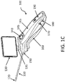
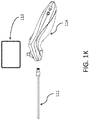
- internal tissue visualization devices of the systems of the invention include an elongated member and a hand-held control unit (such as a probe piece and hand piece as described further below).
- this component of the devices has a length that is 1.5 times or longer than its width, such as 2 times or longer than its width, including 5 or even 10 times or longer than its width, e.g., 20 times longer than its width, 30 times longer than its width, or longer.
- the length of the elongated member may vary, and in some instances ranges from 5 cm to 20 cm, such as 7.5 cm to 15 cm and including 10 to 12 cm.
- the elongated member may have the same outer cross-sectional dimensions (e.g., diameter) along its entire length. Alternatively, the cross-sectional diameter may vary along the length of the elongated member.
- At least the distal end region of the elongated member of the devices is dimensioned to pass through a Cambin's triangle.
- distal end region is meant a length of the elongated member starting at the distal end of 1 cm or longer, such as 3 cm or longer, including 5 cm or longer, where the elongated member may have the same outer diameter along its entire length.
- the Cambin's triangle (also known in the art as the Pambin's triangle) is an anatomical spinal structure bounded by an exiting nerve root and a traversing nerve root and a disc. The exiting root is the root that leaves the spinal canal just cephalad (above) the disc, and the traversing root is the root that leaves the spinal canal just caudad (below) the disc.
- the distal end of the elongated member is dimensioned to pass through a Cambin's triangle
- at least the distal end of the device has a longest cross-sectional dimension that is 10 mm or less, such as 8 mm or less and including 7 mm or less.
- the devices include an elongated member that has an outer diameter at least in its distal end region that is 5.0 mm or less, such as 4.0 mm or less, including 3.0 mm or less.
- the elongated members of the subject tissue visualization devices have a proximal end and a distal end.
- proximal end refers to the end of the elongated member that is nearer the user (such as a physician operating the device in a tissue modification procedure)
- distal end refers to the end of the elongated member that is nearer the internal target tissue of the subject during use.
- the proximal end is also the end that is operatively coupled to the hand-held control unit of the device (described in greater detail below).
- the elongated member is, in some instances, a structure of sufficient rigidity to allow the distal end to be pushed through tissue when sufficient force is applied to the proximal end of the elongate member. As such, in these embodiments the elongated member is not pliant or flexible, at least not to any significant extent.
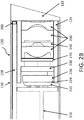
- the visualization devices include a visualization sensor integrated at the distal end of the elongated member, such that the visualization sensor is integrated with the elongated member.
- the visualization sensor is integrated with the elongated member, it cannot be removed from the remainder of the elongated member without significantly compromising the structure and functionality of the elongated member.
- the devices of the present invention are distinguished from devices which include a "working channel" through which a separate autonomous device is passed through.
- the visualization sensor of the present device is integrated with the elongated member, it is not a separate device from the elongated member that is merely present in a working channel of the elongated member and which can be removed from the working channel of such an elongated member without structurally compromising the elongated member in any way.
- the visualization sensor may be integrated with the elongated member by a variety of different configurations. Integrated configurations include configurations where the visualization sensor is fixed relative to the distal end of the elongated member, as well as configurations where the visualization sensor is movable to some extent relative to the distal end of the elongated member.
- Movement of the visualization sensor may also be provided relative to the distal end of the elongated member, but then fixed with respect to another component present at the distal end, such as a distal end integrated illuminator. Specific configurations of interest are further described below in connection with the figures.
- Imaging sensors of interest include miniature imaging sensors that have a cross-sectional area which is sufficiently small for its intended use and yet retains a sufficiently high matrix resolution.
- Imaging sensors of interest are those that include a photosensitive component, e.g., array of photosensitive elements that convert light into electrons, coupled to a circuitry component, such as an integrated circuit.
- the integrated circuit may be configured to obtain and integrate the signals from the photosensitive array and output image data, which image data may in turn be conveyed to an extra-corporeal device configured to receive the data and display it to a user.
- the image sensors of these embodiments may be viewed as integrated circuit image sensors.
- the integrated circuit component of these sensors may include a variety of different types of functionalities, including but not limited to: image signal processing, memory, and data transmission circuitry to transmit data from the visualization sensor to an extra-corporeal location, etc.
- the miniature imaging sensors may be present in a module which further includes one or more of a housing, a lens component made up of one or more lenses positioned relative to the photosensitive component so as to focus images on the photosensitive component, one or more filters, polarized members, etc.
- Specific types of miniature imaging sensors of interest include complementary metal- oxide-semiconductor (CMOS) sensors and charge-coupled device (CCD) sensors.
- CMOS complementary metal- oxide-semiconductor
- CCD charge-coupled device
- the sensors may have any convenient configuration, including circular, square, rectangular, etc.
- Visualization sensors of interest may have a longest cross-sectional dimension that varies depending on the particular embodiment, where in some instances the longest cross sectional dimension (e.g., diameter) is 4.0 mm or less, such as 3.5 mm or less, including 3.0 mm or less, such as 2.5 mm or less, including 2.0 mm or less, including 1.5 mm or less, including 1.0 mm or less.
- the sensor component may be located some distances from the lens or lenses of the module, where this distance may vary, such as 10 mm or less, including 7 mm or less, e.g., 6 mm or less.
- Imaging sensors of interest may be either frontside or backside illumination sensors, and have sufficiently small dimensions while maintaining sufficient functionality to be integrated at the distal end of the elongated members of the devices of the invention. Aspects of these sensors are further described in one or more the following U.S. Patents, the disclosures of which are herein incorporated by reference: 7,388,242 ; 7,368,772 ; 7,355,228 ; 7,345,330 ; 7,344,910 ; 7,268,335 ; 7,209,601 ; 7,196,314 ; 7,193,198 ; 7,161,130 ; and 7,154,137 .
- the visualization sensor is located at the distal end of the elongated member, such that the visualization sensor is a distal end visualization sensor, in these instances, the visualization sensor is located at or near the distal end of the elongated member. Accordingly, it is positioned at 3 mm or closer to the distal end, such as at 2 mm or closer to the distal end, including at 1 mm or closer to the distal end. In some instances, the visualization sensor is located at the distal end of the elongated member.
- the visualization sensor may provide for front viewing and/or side-viewing, as desired. Accordingly, the visualization sensor may be configured to provide image data as seen in the forward direction from the distal end of the elongated member.
- the visualization sensor may be configured to provide image data as seen from the side of the elongate member.
- a visualization sensor may be configured to provide image data from both the front and the side, e.g., where the image sensor faces at an angle that is less than 90° relative to the longitudinal axis of the elongated member.
- Components of the visualization sensor may be present in a housing.
- the housing may have any convenient configuration, where the particular configuration may be chosen based on location of the sensor, direction of view of the sensor, etc.
- the housing may be fabricated from any convenient material. In some instances, non-conductive materials, e.g., polymeric materials, are employed.
- Visualization sensors may further include functionality for conveying image data to an extra-corporeal device, such as an image display device, of a system.
- a wired connection e.g., in the form of a signal cable (or other type of signal conveyance element) may be present to connect the visualization sensor at the distal end to a device at the proximal end of the elongate member, e.g., in the form of one or more wires running along the length of the elongate member from the distal to the proximal end.
- the visualization sensor is coupled to a conductive member (e.g., cable or analogous structure) that conductively connects the visualization sensor to a proximal end location of the elongated member.
- wireless communication protocols may be employed, e.g., where the visualization sensor is operatively coupled to a wireless data transmitter, which may be positioned at the distal end of the elongated member (including integrated into the visualization sensor, at some position along the elongated member or at the proximal end of the device, e.g., at a location of the proximal end of the elongated member or associated with the handle of the device).
- the devices may include one or more illumination elements configured to illuminate a target tissue location so that the location can be visualized with a visualization sensor, e.g., as described above.
- illumination elements also referred to herein as illuminators
- the light sources may be integrated with a given component (e.g., elongated member) such that they are configured relative to the component such that the light source element cannot be removed from the remainder of the component without significantly compromising the structure of the component.
- the light sources may be light emitting diodes (LEDs) configured to emit light of the desired wavelength range, or optical conveyance elements, e.g., optical fibers, configured to convey light of the desired wavelength range from a location other than the distal end of the elongate member, e.g., a location at the proximal end of the elongate member, to the distal end of the elongate member.
- the physical location of the light source, e.g., LED may vary, such as any location in the elongated member, in the hand-held control unit, etc.
- the light sources may include a conductive element, e.g., wire, or an optical fiber, which runs the length of the elongate member to provide for power and control of the light sources from a location outside the body, e.g., an extracorporeal control device.
- a conductive element e.g., wire, or an optical fiber, which runs the length of the elongate member to provide for power and control of the light sources from a location outside the body, e.g., an extracorporeal control device.
- the light sources may include a diffusion element to provide for uniform illumination of the target tissue site.
- Any convenient diffusion element may be employed, including but not limited to a translucent cover or layer (fabricated from any convenient translucent material) through which light from the light source passes and is thus diffused.
- the illumination elements may emit light of the same wavelength or they may be spectrally distinct light sources, where by “spectrally distinct” is meant that the light sources emit light at wavelengths that do not substantially overlap, such as white light and infra-red light, in certain embodiments, an illumination configuration as described in copending United States Application Serial Nos. 12/269,770 and 12/269,772 (the disclosures of which are herein incorporated by reference) is present in the device.
- Distal end integrated illuminators may have any convenient configuration. Configurations of interest have various cross-sectional shapes, including but not limited to circular, ovoid, rectangular (including square), irregular, etc. In some instances the configuration of the integrated illuminator is configured to conform with the configuration of the integrated visualization sensor such that the cross-sectional area of the two components is maximized within the overall minimal cross-sectional area available at the distal end of the elongated member.
- the configurations of the integrated visualization sensor and illuminators may be such that the integrated visualization sensor may occupy a first portion of the available cross-sectional area of the distal end of the elongated member (such as 40% or more, including 50% or 60% or more of the total available cross-sectional area of the distal end of the elongated member) and the integrated illuminator may occupy a substantial portion of the remainder of the cross-sectional area, such as 60% or more, 70% or more, or 80% or more of the remainder of the cross-sectional area.
- the integrated illuminator has a crescent configuration.
- the crescent configuration may have dimensions configured to confirm with walls of the elongated member and a circular visualization sensor.
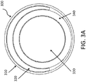
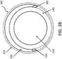
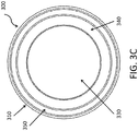
- the integrated illuminator has an annular configuration, e.g., where conforms to the inner wails of the elongated member or makes up the walls of the elongated member, e.g., as described in greater detail below. This configuration may be of interest where the visualization sensor is positioned at the center of the distal end of the elongated member.
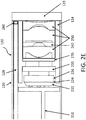
- the elongated member comprises an annular wall configured to conduct light to the elongated member distal end from a proximal end source.
- the distal end of this annular wall may be viewed as an integrated illuminator, as described above.
- the walls of the elongated structure which collective make up the annular wall are fabricated from a translucent material which conducts light from a source apart from the distal end, e.g., from the proximal end, to the distal end.
- a reflective coating may be provided on the outside of the translucent elongated member to internally reflect light provided from a remote source, e.g., such as an LED at the proximal end, to the distal end of the device. Any convenient reflective coating material may be employed.
- integrated illuminators that include a fluid filled structure that is configured to conduct light to the elongated member distal end from a proximal end source.
- a structure may be a lumen that extends along a length of the elongated structure from a proximal end light source to the distal end of the elongated structure.
- lumens may have a longest cross section that varies, ranging in some instances from 0,5 to 4.0 mm, such as 0.5 to 3.5 mm, including 0.5 to 3.0 mm.
- the lumens may have any convenient cross-sectional shape, including but not limited to circular, square, rectangular, triangular, semi-circular, trapezoidal, irregular, etc., as desired.
- the fluid filled structure may be filled with any convenient translucent fluid, where fluids of interest include aqueous fluids, e.g., water, saline, etc., organic fluids, such as heavy mineral oil (e.g., mineral oil having a specific gravity greater than or equal to about 0.86 and preferably between about 0.86 and 0.905), and the like.
- aqueous fluids e.g., water, saline, etc.
- organic fluids such as heavy mineral oil (e.g., mineral oil having a specific gravity greater than or equal to about 0.86 and preferably between about 0.86 and 0.905), and the like.
- the integrated illuminators are made up of an elongated member integrated light conveyance structure, e.g., optical fiber, light conductive annular wall, light conducting fluid filled structure, etc., which is coupled to a proximal end light source.
- the proximal end light source is a forward focused LED.
- bright LEDs e.g., LEDs having a brightness of 100 mcd or more, such as 300 mcd or more, and in some instances 500 mcd or more, 1000 mcd or more, 1500 mcd or more. In some instances, the brightness ranges from 100 to 2000 mcd, such as 300 to 1500 mcd.
- the LED may be coupled with a forward focusing lens that is, in turn, coupled to the light conveyance structure.
- the proximal end LED may be coupled to the light conveyance structure in a manner such that substantially all, if not all, light emitted by the LED is input into the light conveyance structure.
- the LED and focusing lens may be configured such that at least a portion of the light emitted by the LED is directed along the outer surface of the elongated member.
- the forward focused light emitting diode is configured to direct light along the outer surface of the elongated member. As such, light from the proximal end LED travels along the outer surface of the elongated member to the distal end of the elongated member.
- the tissue visualization devices of the invention are configured to reduce coupling of light directly from the integrated illuminator to the visualization sensor.
- the devices are structures so that substantially all, if not all, of the light emitted by the integrated illuminator at the distal end of the elongated structure is prevented from directly reaching the visualization sensor. In this manner, the majority, if not all, of the light that reaches the visualization sensor is reflected light, which reflected light is converted to image data by the visualization sensor.
- the device may include a distal end polarized member.
- distal end polarized member is meant a structure or combination of structures that have been polarized in some manner sufficient to achieve the desired purpose of reducing, if not eliminating, light from the integrated illuminator directly reaching the integrated visualization sensor.
- the light from an LED is polarized by a first polarizer (linearly or circularly) as it enters at lens or prism at the distal tip of the elongated member.
- a visualization sensor such as CMOS sensor, also has a polarizer directly in front of it, with this second polarizer being complimentary to the first polarizer so that any light reflected by the outer prism surface into the visualization sensor will be blocked by this polarizer.
- the distal end polarized member may be a cover lens, e.g., for forward viewing elongated members, or a prism, e.g., for off-axis viewing elongated members, such as described in greater detail below.
- the distal end of the elongated member includes an off-axis visualization module that is configured so that the visualization sensor obtains data from a field of view that is not parallel to the longitudinal axis of the elongated member.
- an off-axis visualization module the field of view of the visualization sensor is at an angle relative to the longitudinal axis of the elongated member, where this angle may range in some instances from 5 to 90°, such as 45 to 75°, e.g., 30°.
- the off-axis visualization module may include any convenient light guide which collects light from an off-axis field of view and conveys the collected light to the visualization sensor.
- the off-axis visualization module is a prism.
- the elongated member may or may not include one or more lumens that extend at least partially along its length.
- the lumens may vary in diameter and may be employed for a variety of different purposes, such as irrigation, aspiration, electrical isolation (for example of conductive members, such as wires), as a mechanical guide, etc., as reviewed in greater detail below.
- such lumens may have a longest cross section that varies, ranging in some instances from 0.5 to 5.0 mm, such as 1.0 to 4.5 mm, including 1.0 to 4.0 mm.
- the lumens may have any convenient cross-sectional shape, including but not limited to circular, square, rectangular, triangular, semi-circular, trapezoidal, irregular, etc., as desired. These lumens may be provided for a variety of different functions, including as conveyance structures for providing access of devices, compositions, etc. to the distal end of the elongated member, as described in greater detail below. Such lumens may be employed as a "working channel”.
- an integrated articulation mechanism that imparts steerability to at least the distal end of the elongated member or a component thereof is also present in the device, such that the elongated member is the elongated member is configured for distal end articulation.
- steerability is meant the ability to maneuver or orient the distal end of the elongated member or component thereof as desired during a procedure, e.g., by using controls positioned at the proximal end of the device, e.g., on the hand-held control unit.
- the devices include a steerability mechanism (or one or more elements located at the distal end of the elongated member) which renders the desired elongated member distal end or component thereof maneuverable as desired through proximal end control.
- a steerability mechanism or one or more elements located at the distal end of the elongated member which renders the desired elongated member distal end or component thereof maneuverable as desired through proximal end control.
- the steering functionality can be provided by a variety of different mechanisms. Examples of suitable mechanisms include, but are not limited to one or more wires, tubes, plates, meshes or combinations thereof, made from appropriate materials, such as shape memory materials, music wire, etc.
- the distal end of the elongated member is provided with a distinct, additional capability that allows it to be independently rotated about its longitudinal axis when a significant portion of the operating handle is maintained in a fixed position, as discussed in greater detail below.
- the extent of distal component articulations of the invention may vary, such as from -180 to +180°; e.g., -90 to +90°.
- the distal probe tip articulations may range from 0 to 360°, such as 0 to +180°, and including 0 to +90°, with provisions for rotating the entire probe about its axis so that the full range of angles is accessible on either side of the axis of the probe, e.g., as described in greater detail below.
- Rotation of the elongated member may be accomplished via any convenient approach, e.g., through the use of motors, such as described in greater detail below.
- Articulation mechanisms of interest are further described in published PCT Application Publication Nos. WO 2009029639 ; WO 2008/094444 ; WO 2008/094439 and WO 2008/094436 ; the disclosures of which are herein incorporated by reference.
- Specific articulation configurations of interest are further described in connection with the figures, below, as well as in United States Application Serial No. 12/422,176 ; the disclosure of which is herein incorporated by reference.
- the internal tissue visualization devices of the invention further include a hand-held control unit to which the elongated member is operably connected.
- a hand-held control unit to which the elongated member is operably connected.
- operably connected is meant that one structure is in communication (for example, mechanical, electrical, optical connection, or the like) with another structure.
- the hand-held control unit is located at the proximal end of the elongated structure, and therefore at the proximal end of the device.
- the control unit is hand-held, it is configured to be held easily in the hand of an adult human. Accordingly, the hand-held control unit may have a configuration that is amenable to gripping by the human adult hand.
- the weight of the hand-held control unit may vary, but in some instances ranges from .5 to 5 lbs, such as .5 to 3 lbs.
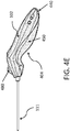
- the hand-held control unit may have any convenient configuration, such as a hand-held wand with one or more control buttons, as a hand-held gun with a trigger, etc., where examples of suitable handle configurations are further provided below.
- the hand-held control unit may include a monitor.
- monitor is meant a visual display unit, which includes a screen that displays visual data in the form of images and/or text to a user.
- the screen may vary, where a screen type of interest is an LCD screen.
- the monitor when present, may be integrated or detachable from the remainder of the hand-held control unit.
- the monitor may be an integrated structure with the hand-held control unit, such that it cannot be separated from the hand-held control unit without damaging the monitor in some manner.
- the monitor may be a detachable monitor, where the monitor can be attached to and separated from the hand-held control unit, as desired, without damaging the function of the monitor
- the monitor and hand-held control unit may have a variety of different mating configurations, such as where the hand-held control unit includes a hole configured to receive a post of the monitor, where the monitor has a structure that is configured to snap onto a receiving structure of the hand-held control unit, etc.
- the monitor when present will have dimensions sufficient for use with the hand-held control unit, where screen sizes of interest may include 10 inches or smaller, such es or smaller, e.g., 5 inches or smaller, e.g., 3.5 inches, etc.
- Data communication between the monitor and the remainder of the hand-held control unit may be accomplished according to any convenient configuration.
- the monitor and remaining components of the hand-held control unit may be connected by one or more wires.
- the two components may be configured to communication with each other via a wireless communication protocol.
- the monitor will include a wireless communication module.
- the distal end of the elongated member is rotatable about its longitudinal axis when a significant portion of the hand-held control unit is maintained in a fixed position.
- at least the distal end of the elongated member can turn by some degree while the hand-held control unit attached to the proximal end of the elongated member stays in a fixed position.
- the degree of rotation in a given device may vary, and may range from 0 to 360°, such as 0 to 270°, including 0 to 180°. Rotation, when present, may be provided by any convenient approach, e.g., through use of motors.
- Devices of the invention may be disposable or reusable. As such, devices of the invention may be entirely reusable (e.g., be multi-use devices) or be entirely disposable (e.g., where all components of the device are single-use). In some instances, the device can be entirely reusable (e.g., where all components can be reused a limited number of times). Each of the components of the device may individually be single-use, of limited reusability, or indefinitely reusable, resulting in an overall device or system comprised of components having differing usability parameters.
- the elongated member is configured to be detachable from the hand-held control unit.
- the elongated member is configured to be readily separable from the hand-held control unit without in any way damaging the functionality of the hand-held control unit, such that the hand-held control unit may be attached to another elongated member.
- the devices are configured so that the hand-held control unit can be sequentially operably attached to multiple different elongated members.
- the elongated member can be manually operably attached to a hand-held control unit without the use of any tools.
- the hand-held control unit has a structure configured to receive the proximal end of the elongated member.
- the hand-held control unit may be re-used simply by wiping down the hand-held control unit following a given procedure and then attaching a new elongated member to the hand-held control unit.
- the device may include a removable sterile covering attached to the proximal end of the elongated member that is configured to seal the hand-held control unit from the environment.
- This sterile covering e.g., in the form of a sheath as described in greater detail below
- the sterile covering may include an integrated clear monitor cover, which may be rigid and configured to conform to the monitor screen. In some instances, the cover may be configured to provide for touch screen interaction with the monitor.
- the hand-held control unit may include a manual controller.
- the sterile covering may include a flexible rubber boot for mechanical controller sealing, i.e., a boot portion configured to associated with the manual controller.
- the sterile covering may include a seal at a region associated with the proximal end of the hand-held control unit. In these instances, the open side of sterile cover prior to use may be conveniently located at the proximal end.
- the open side may be mechanically attached to the handle and closed by a validated sealing method.
- the sterile cover of these embodiments is configured such that when employed, it does not inhibit handle controls or elongated structure and monitor actuation.
- devices of the invention may include a distal end integrated nonvisualization sensor.
- the devices may include one or more non- visualization sensors that are integrated at the distal end of the elongated member.
- the one or more non-visualization sensors are sensors that are configured to obtain non- visual data from a target location.
- Non-visual data of interest includes, but is not limited to: temperature, pressure, pH, elasticity, impedance, conductivity, distance, size, etc.
- Non-visualization sensors of interest include those configured to obtain one or more types of the non-visual data of interest.
- sensors that may be integrated at the distal end include, but are not limited to: temperature sensors, pressure sensors, pH sensors, impedance sensors, conductivity sensors, elasticity sensors, etc.
- Specific types of sensors include, but are not limited to: thermistors, strain gauges, membrane containing sensors, MEMS sensors, electrodes, light sensors, etc. The choice of a specific type of sensor will depend on the nature of the non-visual data of interest.
- a pressure sensor can detect the force applied to a target tissue as it is deformed to determine the elastic modulus of the target tissue.
- a temperature sensor can be employed to detect locally elevated temperatures (which can be used to differentiate different types of tissue, such as to different normal and tumor tissue (where tumors exhibit increased bloodflow and therefore a higher temperature)).
- a properly collimated laser beam could be used to determine the distance to objects in the device field of view or the length scale of objects in the device field of view.
- the integrated non-visualization sensor or sensors may be configured to complement other distal end components of the devices, so as to minimize any impact on the outer dimension of the distal end, e.g., in ways analogous to those described above in connection with integrated illumination elements.
- the devices include a tissue modifier.
- Tissue modifiers are components that interact with tissue in some manner to modify the tissue in a desired way.
- the term modify is used broadly to refer to changing in some way, including cutting the tissue, ablating the tissue, delivering an agent(s) to the tissue, freezing the tissue, etc.
- tissue modifiers are tissue cutters, tissue ablators, tissue freezing/heating elements, agent delivery devices, etc.
- Tissue cutters of interest include, but are not limited to: blades, liquid jet devices, lasers and the like.
- Tissue ablators of interest include, but are not limited to ablation devices, such as devices for delivery ultrasonic energy (e.g., as employed in ultrasonic ablation), devices for delivering plasma energy, devices for delivering radiofrequency (RF) energy, devices for delivering microwave energy, etc.
- Energy transfer devices of interest include, but are not limited to: devices for modulating the temperature of tissue, e.g., freezing or heating devices, etc.
- the tissue modifier is not a tissue modifier that achieves tissue modification by clamping, clasping or grasping of tissue such as may be accomplished by devices that trap tissue between opposing surfaces (e.g., jaw-like devices).
- the tissue modification device is not an element that is configured to apply mechanical force to tear tissue, e.g., by trapping tissue between opposing surfaces.
- the tissue modifier is a low-profile tissue modifier, such as a low-profile biopsy tool or a low-profile cutter.
- tissue modifiers are include tissue cutting structure positioned at the distal of the elongated member. Because the biopsy or cutting tool is low-profile, its presence at the distal end of the elongated member does not substantially increase the outer diameter of the elongated member. In some instances, the presence of the low-profile biopsy tool increase the outer diameter of the elongated member by 2 mm or less, such as 1.5 mm or less, including 1 mm or less. The configuration of the low-profile biopsy tool may vary.
- the low-profile biopsy tool comprises an annular cutting member concentrically disposed about the distal end of the elongated member and configured to be moved relative to the distal end of the elongated member in a manner sufficient to engage tissue.
- the annular cutting member may or may not be configured as a complete ring structure, where the ring structure is movable in a longitudinal manner relative to the distal end of the elongated member (such that it may be moved along the elongated member towards and away from the proximal end of the elongated member).
- the distal edge of the ring structure may be movable some distance beyond the distal end of elongated member, where this distance may vary and in some instances is 10 mm or less, such as 5 mm or less, including 3 mm or less.
- the distal edge of the ring structure may be sharp in order to penetrate tissue, and may include one or more tissue retaining structures, such as barbs, hooks, lips, etc., which are configured to engage the tissue and stably associate the engaged tissue with the ring structure, e.g., when the ring structure is moved longitudinally along the elongated member towards the proximal end.
- tissue retaining structures such as barbs, hooks, lips, etc.
- cutting tools e.g., as described.
- the distal end integrated visualization sensor is present as an RF-shielded visualization module.
- the visualization sensor module of these embodiments is RF-shielded
- the visualization sensor module includes an RF shield that substantially inhibits, if not completely prevents, an ambient RF field from reaching and interacting with circuitry of the visualization sensor.
- the RF shield is a structure which substantially inhibits, if not completely prevents, ambient RF energy (e.g., as provided by a distal end RF electrode, as described in greater detail blow) from impacting the circuitry function of the visualization sensor.
- Visualization sensor modules of devices of the invention include at least a visualization sensor.
- the devices may further include a conductive member that conductively connects the visualization sensor with another location of the device, such as a proximal end location. Additional components may also be present in the visualization sensor module, where these components are described in greater detail below.
- the RF shield of the visualization sensor module may have a variety of different configurations.
- the RF shield may include an enclosure element or elements which serve to shield the circuitry of the visualization sensor from an ambient RF field.
- the RF shield is a grounded conductive enclosure component or components which are associated with the visualization sensor, conductive member and other components of the visualization sensor module.
- the visualization sensor of the visualization sensor module is present in a housing, where the housing may include a grounded outer conductive layer which serves as an RF shield component. In these instances, the RF shield is an outer grounded conductive layer.
- the conductive enclosure or enclosures of the RF-shielded visualization sensor module may be fabricated from a variety of different conductive materials, such as metals, metal alloys, etc., where specific conductive materials of interest include, but are not limited to; copper foils and the like.
- the RF shield is a metallic layer. This layer, when present, may vary in thickness, but in some instances has a thickness ranging from 0.2mm to 0.7mm, such as 0.3mm to 0.6mm and including 0.4mm to 0.5mm. Additional details regarding RF-shielded visualization modules may be found in United States application serial no. 12/437,865 ; the disclosure of which is herein incorporated by reference.
- the may include a collimated laser configured to emit collimated laser light from a distal region of the elongated member, such as the distal end of the elongated member.
- the collimated laser components of these embodiments may be configured for use for a variety of purposes, such as but not limited to: anatomical feature identification, anatomical feature assessment of sizes and distances within the field of view of the visualization sensor, etc.
- the devices of the invention may be fabricated using any convenient materials or combination thereof, including but not limited to: metallic materials such as tungsten, stainless steel alloys, platinum or its alloys, titanium or its alloys, molybdenum or its alloys, and nickel or its alloys, etc.; polymeric materials, such as polytetrafluoroethylene, polyimide, PEEK, and the like; ceramics, such as alumina (e.g., STEATITETM alumina, MAECORTM alumina), etc.
- metallic materials such as tungsten, stainless steel alloys, platinum or its alloys, titanium or its alloys, molybdenum or its alloys, and nickel or its alloys, etc.
- polymeric materials such as polytetrafluoroethylene, polyimide, PEEK, and the like
- ceramics such as alumina (e.g., STEATITETM alumina, MAECORTM alumina), etc.
- the devices may include a stereoscopic image module.
- stereoscopic image module is meant a functional module that provides a stereoscopic image from image data obtained by the device. As such, the module provides a user via the monitor with the perception of a three-dimensional view of an image produced from the image data obtained by the device.
- the module is described in terms of "images", and it should be understood that the description applies equally to still images and video.
- the device may include two or more distinct visualization sensors (e.g., CMOS cameras as reviewed above) or a single visualization sensor via which the image data is collected and employed by the stereoscopic image module to provide the stereoscopic image.
- the elongated member includes first and second visualization sensors
- the stereoscopic imaging module is configured to process imaged data provided by the first and second visualization sensors to produce the stereoscopic image.
- any convenient stereoscopic image processing program may be employed.
- FIG. 10 illustrates a block flow diagram of a technique to produce stereoscopic images from image data, according to one embodiment.
- Left and right image data are obtained (as represented by blocks 1005), either sequentially from a single visualization sensor that is moved from a first position to a second position or, if two visualization sensors are present, sequentially or simultaneously.
- the left and right Image data account for the different locations and perspectives associated with each respective position of the same visualization sensor or respective positions of the two distinct visualization sensors.
- the image data for the first and second images may include distortions, and an algorithm may be employed, for example, in which the left and right image data are first warped as shown via a calibration element to remove lens distortion, as represented by blocks 1010. Any convenient algorithm may be employed. Algorithms of interest include those described in " Geometric Calibration of Digital Cameras through Multi-view Rectification" by Luca Lucchese (Image and Vision Computing, Vol.
- Any convenient stereo and image fusion algorithms may be employed, such as but not limited to those described in: " Scene Reconstruction from Multiple Cameras” by Richard Szeliski (Microsoft Vision Technology Group ; see also, http://research.microsoft.com/pubs/75687/Szeliski-ICIP00.pdf); "A parallel matching algorithm for stereo vision", by Y. Nishimoto and Y. Shirai (IJCAI-1985-Volume 2, pg.
- Stereo algorithms compute range information to objects seen by the visualization sensors by using triangulation. Objects seen at different viewpoints will result in the object at different locations in the image data for the first and second visualization sensors.
- the disparity, or image difference is used in determining depth and range of objects.
- Corresponding pixel points within the image data for the first and second visualization sensors may be identified and used in the determination of disparity line, as represented by block 1024. Because the first and second visualization sensors are at different locations and hence have different perspectives, the same object present in image data for the first and second visualization sensor may be at different pixel coordinate locations.
- Triangulation may be implemented, as represented by block 1026, based on geometry associated with the locations of the first and second visualization sensors may be used to determine depth and range of objects seen by the visualization sensors.
- Triangulation computations are applied to derive range data, and the resultant range (or depth) map can be overlayed on the image display, as desired. This is represented at block 1028 in FIG. 10 .
- Stereoscopic images taking into account three-dimensional depth information can thus be reconstructed from image data from the first and second visualization sensor.
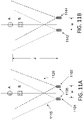
- FIGS. 11B illustrates slightly offset visualization positions, according to certain embodiments.
- FIG. 11B illustrates two visualization sensors, i.e., 1142 for a first view of objects A and B and 1144 for a second view of objects A and B.
- the depth and range of the object is found in a similar manner as for FIG. 11A , as described in more above.
- stereoscopic image modules that are configured to provide a stereoscopic image from data obtained by a single image sensor.
- the image sensor is configured to provide to the stereoscopic image module consecutive offset image data of the target tissue location, which consecutive offset image data are then employed by the stereoscopic image module to provide the desired stereoscopic image.
- consecutive offset image data is meant image data that includes at least data from a first view of a target tissue location and data from a second view of the same target location, where the second view is offset from the first view.
- the second view may be offset from the first view by any convenient distance, for example 1 mm or less, including .5 mm or less.
- the first and second offset views may be obtained using any convenient approach.
- the single visualization sensor is moved from a first position to a second position in order to obtain the desired offset image data.
- the single visualization sensor may be moved from the first to the second positions using any convenient manner, e.g., by a mechanical element that physically moves the sensor from the first to the second position.
- the desired offset views may be obtained with a single visualization sensor operatively coupled to an optical guide system (which may include one or more of lenses, mirrors, filters, etc.) configured to provide the desired first and second offset views.
- the first and second offset views may be provided to the single visualization sensor by including a first and second lens systems which alternately convey image data to the visualization sensor.
- the offset views may also be provided, for example, by including a single lens system with mirrors configured to provide the lens with two or more different views.
- the frequency with which the first and second offset views are obtained may vary, where in some instances the frequency may range from 1 to 30 frames/sec, such as 1 to 15 frames/sec.
- Various systems may be implemented to provide multiple views with a single camera. Systems of interest include, but are not limited to, those described in: " Scalable Multi-view Stereo Camera Array for Real World Real-Time Image Capture and Three Dimensional Displays" by S.
- FIG. 11A illustrates a single visualization sensor 1105 which is moved to two different positions (1101 and 1102) to sequentially obtained image data, which sequentially obtained image data is employed by a stereoscopic image module to produce a stereoscopic image of objects A and B.
- the first and second visualization positions 1101 and 1102 are at an offset width W from one another, which may vary, ranging in some instances from 1 mm or less, such as .5 mm or less.
- Objects A and B located at a focal plane distance Z are seen at different perspectives for the first and second positions (shown by dotted lines 1115, 1120, respectively). The difference in viewing perspectives is reflected in the image data obtained by the single image sensor from the first and second positions.
- first visualization sensor 1105 sees objects A & B off to the right of center when in position 1101 and sees objects A and B off to left of center when in position 1102.
- the disparity between the two views is used to determine depth and range of objects A and B.
- the stereoscopic image module may be implemented in a video processor module configured to receive image data obtained by the one or more visualization sensors.
- the stereoscopic image module processes the image data to provide stereoscopic image data for display on a display.
- devices of the invention include an image recognition module.
- Image recognition modules of interest are those that are configured to receive image data and compare the received image data with a reference that includes at least one of color descriptor data and anatomical descriptor data to make a determination as to whether an alert signal should be generated.
- the term "reference" is used herein to refer to data in any format, e.g., saved as one or more image files, etc., that is for one or more reference images, e.g., where the data can be used by an appropriate processor to produce one or more reference images.
- a reference includes at least a first set of reference image data for a first reference image, in some instances a reference also includes a second set of reference image data for a second reference image.
- a reference may include sets of reference image data for multiple reference images, e.g., 2 or more, 5 or more, 10 or more, 25 or more, 50 or more, 100 or more, 1000 or more, 1500 or more, 2000 or more, 5000 or more, 10, 000 or more etc., reference images.
- Reference images are predetermined images of a region of interest. As the reference images are predetermined, they are images that have been produced independently of the image data that is received by the image processing module. In some instances, the reference images are images that exist prior to obtainment of the image data that is received by the image processing module.
- the reference images may be images that are obtained from the same subject (e.g., person) that is being visualized during a given procedure (e.g., where the reference images were obtained from the subject prior to a given procedure) or from a different subject (e.g., person).
- the reference images may be produced de novo, such that they are not produced from image data obtained from any actual subject but instead are designed, e.g., by using manual or computer assisted graphic protocols.
- Reference images that make up the reference may differ from each other in a number of ways.
- any two given reference images may be images of regions of interest of different internal tissue locations.
- the reference may include first and second pre-determined images that differ from each other with respect to a pre-determined internal tissue location.
- the reference may include images of at least a first tissue location and a second tissue location.
- the first and second tissue locations may be locations that a given device may be expected to image during a given procedure, such as during a surgical procedure.
- the reference includes multiple images of different locations that a given visualization sensor should image during a given procedure if the procedure is performed correctly.
- the reference may also include images of different tissue locations that a visualization sensor should not see during a given procedure, e.g., images of tissue locations that should not be viewed by the sensor if the given procedure of interest is being performed correctly. Accordingly, some references may include multiple images that track the location of a device when correctly and incorrectly positioned during an entire procedure, such as an entire surgical procedure.
- the sets of image data in the reference may include one or more color descriptor data and anatomical descriptor data.
- color descriptor data is meant data which is based on the particular color of a given internal tissue site and components thereof.
- an internal tissue site may include one or more tissues that each has a distinct color.
- different tissues such as muscle, nerve, bone, etc.
- This distinct color may be present in the reference image as color descriptor data, and employed by the image processing module.
- anatomical descriptor data is meant data which is based on the particular shape of one or more tissue structures at the internal tissue site.
- different tissues such as muscle, nerve, bone, etc., have different shapes. These different shapes are present in the image data as anatomical descriptor data.
- the image recognition module compares received image data of an internal tissue site (e.g., obtained during a given procedure of interest) with the reference.
- the comparison performed by the image recognition module may be achieved using any convenient data processing protocol.
- Data processing protocols that may be employed in this comparison step may compare the received image data and reference based on color descriptor data and/or anatomical descriptor data.
- Data comparison protocols of interest include, but are not limited to: mean absolute difference between the descriptors of data and stored values such as mean color intensity, and, the degree of correlation between principle axis of the structure and stored values.
- the image recognition module may be configured to automatically select the appropriate images from a reference to compare against the received image data.
- the image recognition module is configured to compare the received image data with the reference by selecting an appropriate set of reference image data based on a determined positional location of the device. For example, the image recognition module may obtain positional information about the device (e.g., as may be obtained from sensors on the device or manually input and associated with a given image) and then select reference images that are for the same positional location as the device when the device obtained the image data being received.
- the image recognition module may automatically select appropriate sets of image data based on similarity parameters. For example, the image recognition module may automatically select the most similar sets of image data from the reference to use in the comparison step.
- the image recognition module compares the received image data with the reference in order to determine whether an alert signal should be generated, In other words, the output of the image recognition module is a decision as to whether an alert signal should be generated. If an image recognition module determines that an alert signal should be generated, it may generate the alert signal or instruct a separate module of the system to produce an alert signal.
- the alert signal when generated, may vary depending on the nature of the system.
- An alert signal may be a warning signal about a given system parameter or a signal that confirms to an operator of the system that a given system parameter of interest is acceptable.
- an alert signal may include functional information about a device.
- an alert signal may include information that a given device is functioning properly.
- an alert signal may include positional information about a device.
- an alert signal may include information as to whether or not a given device is correctly spatially positioned.
- the alert signal may contain information that a tissue modifier of the device is contacting non-target tissue, such that the tissue modifier is not correctly spatially positioned.
- the system may be configured to employ an alert signal in a variety of different ways.
- the system may be configured to provide the alert signal to a user of the system, e.g., via an alert signal output of the system.
- the system may be configured to automatically modulate one or more operational parameters of the system based on the generation of an alert signal. For example, where the image processing module determines that a tissue modifier is contacting non-target tissue and therefore generates an alert signal, the alert signal may automatically modulate operation of the tissue modifier, e.g., by turning it off. in some instances, the alert signal may automatically shut the system down.
- the stereoscopic module and image recognition modules may be implemented as software, e.g., digital signal processing software; hardware, e.g., a circuit; or combinations thereof, as desired.
- the devices may include a conveyance structure configured to convey an item between the distal end of the elongated member and an entry port positioned at a proximal end of the device, e.g., associated with the proximal end of the elongated member or associated with the hand-held control unit.
- This conveyance structure may have any convenient configuration, where in some instances it is a "working channel" disposed within the elongated member. When present as a working channel, the channel may have an outer diameter that varies, and in some instances has an outer diameter of 3 mm or less, such as 2 mm or less and including 1 mm or less.
- the conveyance structure may be configured to transport items, e.g., fluids, medicines, devices, to an internal target site or from an internal target site.
- the proximal end entry port of the conveyance structure may vary, and may be configured to be operably coupled to a variety of different types of components, such as but not limited to: aspiration units, fluid reservoirs, device actuators, etc.
- devices of the invention may be configured for wireless data transmission, e.g., to provide for one or more of: transmission of data between various component of the device, transmission of data between components of the device and another device, such as hospital information system, separate monitor, etc.
- Any convenient wireless communication protocol may be employed, where in some instances wireless communication is implemented as one or more wireless communication modules.
- a video processor module may be present and be configured to control the one or more distinct visualization sensors by sending camera control data to a camera module including the visualization sensor(s).
- the video processor may also be configured to receive sensor data from one or more sensors and/or tools; and further, may be configured to control the sensors and/or tools by sending sensor control data to a sensor module including the one or more sensors and/or tools.
- the various sensors may include, but are not limited to, sensors relating to pressure, temperature, elasticity, ultrasound acoustic impedance, laser pointer to identify and/or measure difference to sensors, etc.
- the various tools may include, but are not limited to, a measurement scale, teardrop probe, biopsy probe, forceps, scissors, implant device, IR lighting, ultrasound measurement device, cutting tool, etc.
- sensor data may also be included with the image data for processing by the stereoscopic image module, in order to provide the stereographic images.
- the devices of the invention include an updatable control module, by which is meant that the devices are configured so that one or more control algorithms of the device may be updated. Updating may be achieved using any convenient protocol, such as transmitting updated algorithm data to the control module using a wire connection (e.g., via a USB port on the device) or a wireless communication protocol. The content of the update may vary. In some instances, a hand-held control unit is updated to configure the unit to be used with a particular elongated member.
- the update information may be transmitted from the particular elongated member itself, such that upon operable connection of the elongated member to the hand-held control unit, update information is transferred from the elongated member to the hand-held control unit that updates the control module of the hand-held control unit such that it can operate with that particular elongated member.
- the update information may also include general functional updates, such that the hand-held control unit can be updated at any desired time to include one or more additional software features and/or modify one or more existing programs of the device.
- the update information can be provided from any source, e.g., a particular elongated member, the internet, etc.
- FIGS. 1A-1K illustrate one embodiment a self- contained, portable diagnostic imaging device of the invention.
- the hand-held, self- contained, portable diagnostic imaging device 100 illustrated in these figures includes a hand piece 114 and a removably attached elongated member 111 having a distal end integrated CMOS sensor, which is referred to herein as a "probe piece.” See FIG. 1K .
- the probe piece As shown in FIG. 1A and 1C , includes a distal tip 120, an elongated tubular structure 110, and a mechanical connector 150 to the hand piece.
- the hand piece from an external view, as shown in FIG.
- FIGS. 1A and 1C includes a rotatable and removable monitor unit 113 made up of a monitor 130 and a monitor mount 135 that may be attached to either the monitor housing or the top part of the hand piece depending on the embodiment, a single port 170, such as a USB port, for use as an input for programming or as an output for video and still images, an on/off switch 180 for managing power input to the device, a top cover 165, a bottom cover 160, switches for image capture and data transfer and control 145, and a switch for controlling the rotation of the probe piece 140.
- This switch 140 generally has three positions for controlling the motor rotation, one position to rotate the motor clockwise, one position to rotate the motor counterclockwise, and a position in the center that is neutral.
- FIGS. 1D and 1E there is a battery door 190 for the purpose of accessing the battery 195.
- the device Internally viewed, the device additionally contains a battery 195 that may be rechargeable, an electronic control board 190, and connectors 199 for ail electrical and optical components of the device, to and from the electronic control board 190, as shown in FIG. 1B .
- a battery 195 that may be rechargeable
- an electronic control board 190 that may be rechargeable
- connectors 199 for ail electrical and optical components of the device, to and from the electronic control board 190, as shown in FIG. 1B .
- a lens 122 such as a prism lens, or a flat lens (e.g., cover glass), and a CMOS visualization sensor (referred to herein as a camera)124.
- a wire 128 for electrically connecting the camera 124 to a connector 199 on the electronics board 190.
- an illuminator 26 is arranged within the probe piece so as to provide lighting at the distal tip 120, and is connected to the electronic control board 190 at the connectors 199.
- a geared motor 156 is connected to the probe piece via a geared intermediary piece 154.
- the connection between the geared motor 156 and the intermediary piece 154 of the probe piece is oriented in such a way as to allow for the rotation of the probe piece both counterclockwise and clockwise.
- the connector 150 linking the probe piece to the hand piece does not rotate with the intermediary piece 154.
- an intermediary piece 155 for example, a rubber to rubber contact connection.
- Both the motor 157 and the intermediary piece 155 are oriented in such a way as to allow for the rotation of the probe piece both counterclockwise and clockwise.
- the connector 150 linking the probe piece to the hand piece does not rotate with the intermediary piece 155.
- a connector 137 for electrically coupling the monitor mount 135 to the electronic board 190.
- the connector 137 is configured to allow for the rotation of the monitor mount 135, and thus the monitor 130 connected to the monitor mount 135, without binding, breaking or kinking of the connector 137 or the associated wiring that connects the connector 170 to the electronic board 190.
- the portable diagnostic imaging system 100 may include an element to transport material, medicine and implants to and from a point external to the hand piece and external to the distal tip 120 of the probe piece, e.g., a lumen configured as a working channel.
- a port connection 115 such as a luer connector for connecting to other luer connectors, for example a barbed connector for connecting to tubing, like a compression connector for connection to tubing.
- This port connector 115 may be located and protrude from either external half of the hand piece 165 and 160, and at any location convenient to the use of the device.
- a conduit that connects the port 115 to a port 391, as shown in FIGS. 3B and 3D located at the very distal end of the distal tip 120 of the probe piece whereby a material, medicine or implant may be delivered from the hand piece 100.
- the material, medicine or implant may be aspirated into the port 391 at the distal tip 120 of the probe piece, and be transported through a conduit within the probe piece and hand piece, exiting through the port 115 located on the hand piece.
- devices of the invention may include an electronic board 190.
- FIG. 1I shows one embodiment of an electronic board 190 and its associated components.
- one group of components that the electronic board 190 has electrically attached to it are electronic components of the control circuitry represented as blocks 146 and 147.
- there are two locations for electronic components 146 and 147 on the electronic board 190 but there may only be required, in other embodiments of the invention, electronic components located on one side or the other of the electronic board 190, and not necessarily to the footprint of the electronic components 146,147 as suggested in FIG. 1I .
- an electrical connector 170 for transmitting data to and from the electronic board 190 to an external transmitting or receiving means.
- the electrical connector 170 may be used to program a chip that may be located in the electronic component area or areas of 146 and/or 147 of the electronic board 190, for example with a computer.
- the electrical connector 170 may be used for downloading video or still images that are captured by the camera that is located at the distal tip 120 of the probe piece means and stored in a memory chip that may be located in the electronic component area or areas of 146 and/or 147 of the electronic board 190. Additionally this memory chip may be removable from the present invention or reattached to the present invention.
- the electronic connector 170 may be used to send video signal to an external monitor.
- the electrical connector 170 may have an external device, such as a wireless adapter, should a wireless system not already be included within present invention, as it may be in one embodiment, attached to it to wirelessly send data from the present invention to an external receiving device, for example a monitor, or send and receive data wirelessly to and/or from, for example, a computer or other computing devices.
- a switch 180 for turning on and off the present device.
- the switch 180 would allow for power from the battery 195, shown in FIG 1B , to pass to the electronic board 190.
- switches 145 for control of the present invention, as shown in FIG. 1I .
- the number of switches 145 for example 1 to 10 switches, may be present on this device depending the number of controls required for different embodiments of the present invention.
- One example of what a switch 145 may control is image capture from the camera.
- Another example of what a switch may be used for is sending data, such as still images, from a memory source within this device, to an external source, for example a computer.
- Yet another example of what a switch may be used for is to control the illumination within the present invention.
- a switch 140 for controlling the rotation of the motor which then controls the rotation of the catheter piece is attached to the electronic board 190, such as to electronic components located at either/or electronic component areas 146 and 147, and a switch 140 for controlling the rotation of the motor which then controls the rotation of the catheter piece, in one embodiment, the switch 140 may be configured to have one of three positions whereby there is a neutral position in the middle, for example, and a position on either side on the neutral position for rotating the motor either clockwise or counterclockwise as would be determined by the user's input.
- connectors 199 Another attachment to the electronic board 190, and where desired to electronic components located at either/or electronic component areas 146 and 147, are a series of connectors 199. These connectors 199 may serve a variety of functions, including for the control of the motors 157 or 156, the camera 122, the lighting 126, and the monitor 130. In another embodiment, the connectors are linked to a sensor located at the distal tip 120 of the catheter.
- the portable diagnostic imaging system 100 has a connector to connect and detach the probe piece 111 of the device 100 from the hand piece 112 of the device 100.
- the purpose of attaching and detaching the probe piece 111 of the device 100 from the hand piece 112 of the device 100 is to change the probe piece 111 from one embodiment of the probe piece 111 to another as would be the case where the two of more different probe pieces 111 have different functionality as required by the practitioner.
- the purpose of detaching the probe piece 111 of the device 100 from the hand piece 112 is for the sterility requirements that the practitioner must follow, e.g., for a medical application. For example, should the practitioner require to use the device 100 with two of more patients, the practitioner would be required to dispose of the probe piece 111, and attach a new sterile probe piece 111 to hand piece 112.
- the monitor 113 may also be detachable from the hand piece 114 as shown in FIG. 1K .
- the functionality of detaching the monitor 113 from the hand piece 114 is to aid the practitioner with the viewing of the camera in a different location.
- the monitor 113 would be wirelessly connected to the hand piece 114 to allow video signals to be sent from the electronics within the hand piece 114 to the monitor 113.
- FIG. 2A shows a section view of the distal tip 120 of the probe piece 111. Shown in FIG. 2A are the necessary components that make up a camera and lighting module to produce an image that can be displayed on a monitor.
- the camera and lighting module as described allow viewing off-axis, and therefore make up an off-axis viewing module, as explained in greater detail below.
- a prism lens 122 covers the end of the elongated member 110 of the probe piece 111.
- the purpose of the prism lens 122 is to allow for imaging at angle to the axis of the probe piece, for example, 30 degrees.
- Proximal to the prism lens in one embodiment, is shown a camera housing 124.
- CMOS imaging chip 220 Contained within this housing 124 is a series of lenses 250, an aperture 240, filters 230 and 226 and a CMOS imaging chip 220 that is attached to filter 226 by adhesive 224.
- the chip 220 is mechanically and electrically attached to a circuit board 210 that transmits signals between the chip 220 and the electronics within the hand piece of the present invention.
- an integrated illuminator 128 located within the distal tip 120 of the catheter piece.
- the integrated illuminator may be a fiberoptic bundle connected to an LED or other light source that is powered from the battery within the hand piece.
- the integrated illuminator 128 may be a made from a light piping material such as a plastic or light transmitting hard resin or light transmitting liquid or air, all of which would be connected to an LED or other light source within the hand piece 114, as mentioned previously.
- a cover glass 123 is located in place of the prism lens 122 of FIG. 2A .
- a cover glass 123 allows the viewing of an image that is directly in from of the sensor chip 224.
- This configuration is an example of an "on-axis" imaging module.
- a visualization module may include a filtering system.
- FIG. 2B is one embodiment of a filtering system for controlling the incidence of light form the integrated illuminator 128 or other source of light, into the chip 220.
- Filter 260 is polarized opposite to filter 270 so that unintended light, particularly from the integrated illuminator 128 contained within the distal tip 120 of the catheter piece is less likely to enter the camera.
- the polarizing filter 270 is located distal to the lenses 250 contained within the camera housing 124, but proximal to the prism lens.
- FIGS. 2E and 2F are embodiments of a filtering system for controlling the incidence of light form the integrated illuminator 128 or other source of light into the sensor chip 220 as previously described and shown in FIGS. 2B and 2C1 with the exception that the filters as shown in FIGS. 2E and 2F , are proximal to a cover glass 123 rather than a prism lens 122 as shown in FIGS. 2B and 2C .
- FIGS. 3A-3D there is shown an endways view of several embodiments for the mechanical arrangement of components located at the distal end 300 of a probe piece of device.
- an endways view of the probe- piece wall 310 has located eccentrically within its inner perimeter, a camera housing 340, camera lens and visualization sensor 330.
- an endways view of an integrated illuminator 3201 such as the end of a fiber optic bundle, is located in the space between the camera housing 340 and inner perimeter of the probe piece wall 310.
- the integrated illuminator 320 has a crescent configuration so as to conform to the camera housing structure.
- FIG. 3B illustrates the end of a probe piece that is analogous to that shown in FIG. 3A .
- a non-visualization sensor e.g., a pressure sensor
- Port 391 may be in operable connection to a lumen running at least part of the length of the probe piece, and may serve a variety of functions, including those described above, such as delivery of an active agent, etc.
- FIG. 3C Another embodiment, for the mechanical arrangement of components located at the distal end 300 of the device, is shown in FIG. 3C .
- An endways view of the probe piece wall 310 has located concentrically within its inner perimeter, a camera housing 340 and camera lens and visualization sensor 330.
- an endways view of an integrated illuminator 350 is located in the space between the camera housing 340 and inner perimeter of the probe piece wall 310.
- FIG. 3D illustrates the end of a probe piece that is analogous to that shown in FIG. 3C .
- FIG. 3D illustrates the end of a probe piece that is analogous to that shown in FIG. 3C .
- a non-visualization sensor e.g., a pressure sensor
- a port 391 is located on the opposite side of the probe piece.
- Port 391 may be in operable connection to a lumen running at least part of the length of the probe piece, and may serve a variety of functions, including those described above, such as delivery of an active agent, etc.
- Data transfer from the sensor to a control module in the hand piece of the device may be accomplished using any convenient approach.
- transferring information from sensor 390 to the electronics within the hand piece is accomplished by a connection to the electronic board 190 at a point 392 via wires 394 that are passed through the probe piece from the sensor 390 into the hand piece, as shown in FIG. 3E .
- FIG. 3F illustrates one embodiment of a connection from a port 391, located at the distal end of the probe piece, to a port 398 in the hand piece via an open conduit 396, for example a tube, that passes between the ports, 391 and 398, and through the inside of the probe piece.
- FIGS. 4A-4F there is shown several different embodiments configured to maintain sterility of the hand piece.
- a sterile sheath or bag
- 400 or 404 that is sealably connected to the probe piece 111 at a location 460 circumferential to the probe piece 111.
- the sheath 400 or 404 includes a sheath piece 450.
- the sheath may also include one or more additional components, such as a clear monitor cover 420 and/or or a flexible boot 430.
- the sheath 400 or 404 is wrapped over an embodiment of the hand piece 112 ( FIG. 4C and 4D ), 102 ( FIG. 4E ), 104 ( FIG.
- a seal is provided for sealing the sheath piece 450 at the opening 440 around an embodiment of the hand piece 112, 102, 104; for example, folding over the sheath piece 450 at the opening 440 and sealing it with tape or another method.
- an embodiment of the sheath 400 may have connected and sealed to it a rigid and clear monitor cover 420 and a flexible boot 430.
- the purpose of the monitor cover 420 is to allow for the functionality of the monitor means of the hand piece 112, while maintaining the sealability of the sheath 400.
- the monitor cover 420 may be comprised of a clear plastic, for example, that has the mechanical features to snap over the monitor means; the purpose of which is to allow for a clear view of the monitor for the practitioner of the present invention.
- the flexible boot 430 may be comprised of rubber, for example, that has the mechanical features to snap over the control elements, for example switches, of the hand piece 112, while maintaining the sealability of the sheath 400.
- the hand piece sheath portion 450 may then be sealed over the hand piece 112 at a location 440 as described previously.
- FIG. 4B there is connected and sealed to it a flexible boot 430 as mentioned in the above embodiment, but without a monitor cover 420, FIG. 4A .
- the purpose of this embodiment of the sheath 404 is to be able to seal a hand piece 102, FIG. 4E , that has no monitor attached to it.
- FIG. 4F there is connected and sealed to the sheath piece 450 a flexible boot 430 as mentioned in the latter embodiment and without a monitor cover 420, FIG. 4A , for the purpose of sealing a hand piece 104 that has no feature 480, FIG. 4E , where the monitor may mount, located on the hand piece at a location 470, FIG. 4F .
- a control cable 550 for example a twisted wire or rod, is connected at a distal location 530 to and within the tubular probe piece portion 540, and behind a distal lens 520.
- the control cable 550 joins to a control, for example a mechanical switch, within the hand piece, where it may be actuated, for example pulled toward the proximal end of the device.
- the actuation of the control cable in this method, would cause the flexible portion 500 of the probe piece to bend as shown in FIG. 5B .
- the flexible portion 500 of the probe piece may then be returned to the position as shown in FIG. 5A , for example, by a spring means, or possibly by the actuation of the control cable 550 towards the distal end of the device.
- the flexible portion 500 of the probe piece may be constructed in such a way as to allow for flexion of this portion of the probe piece, in one or more directions.
- the embodiment as shown in FIGS. 5A-5B shows one example of how to create the flexible portion 500 of the probe piece, by having a series of cut-outs covered with a hydrophobic tube 510.
- the flexible portion 500 is configured to flex in one direction, that being shown in FIG. 5B .
- the purpose of the hydrophobic tubing surrounding the cut-outs 510 is to prevent material ingress into the probe piece, for example water, while allowing for the flexion of the flexible portion 500.
- this flexible portion 500 may be flexible in a plurality of directions and degrees, and may be controlled by a concomitant number of control cables connected to switches or other mechanical controls within the hand piece.
- FIG. 5C Another embodiment for the viewing of the camera at an angle, for example 30 degrees from the central axis of the catheter piece, is shown in FIG. 5C .
- the bend 560 in this portion of the catheter piece 505 may be rigid, such as the case of a bent steel tube, or flexible, as would be the case, for example, of a formed flexible plastic tube.
- the formed bend 560 is flexible, there may be a spring inside, such as a NITINOLTM wire, that is configured to provide for the temporary bending of this portion 505 into a straight position, aligned with the central axis of the catheter piece, by the practitioner, and when released would bend back to the formed position.
- a spring inside such as a NITINOLTM wire
- FIGS. 6A-6B there is shown one embodiment of a controllable low-profile biopsy tool.
- FIG. 6A shows a section view of one embodiment of the distal tip 120 of the probe piece.
- FIG. 6B shows an external side view of one embodiment of the distal tip 120 of the probe piece.
- a low-profile biopsy tool that includes a cutting piece 610 and a control piece 612.
- Cutting piece 610 is concentrically disposed about the distal end of the probe piece 120, and configured to be moved relative to the distal end of the probe piece 120 in a manner sufficient to engage tissue.
- the control piece 612 for example a rod, may be attached to the cutting piece 610, and it may extend to the hand piece where is would be actuated by a mechanical means.
- FIG. 7 there is shown one embodiment of a cutting or scraping tool.
- This figure shows a section view of one embodiment of the distal tip 120 of the probe piece.
- a low- profile cutting or scraping tool that includes a cutting piece 710 and a control piece 712, and is concentrically disposed about the distal end of the probe piece 120.
- This tool may be configured to be moved relative to the distal end of the catheter piece 120 in a manner sufficient to engage material, for example tissue.
- this tool may be configured to be rotated circumferentially to the distal end of the catheter piece 120 in a manner sufficient to engage material, for example tissue.
- this tool may be fixed at the distal end of the catheter piece 120.
- the control piece 712 for example a tube or rod, may be attached to the cutting piece 710, and it may extend to the hand piece where is would be actuated by a mechanical means should that be necessary for the particular embodiment of the tool.
- FIG. 8 there is shown one embodiment of a deployable sensor 812 incorporated into a device of the present invention 100 by a wired connection 810.
- a wireless communication module may be employed instead of wired connection 810.
- the wired connection passes through a port 391, as shown in FIGS.
- the wired connection 810 then connects to the electronics board within the hand piece where its output may be processed. This processed output may be displayed on a monitor and/or recorded to a memory chip on the electronics board, for example.
- the wired connection 810 may have sufficient slack, for example extra wire length, so as to allow the sensor to be located at some distance, for example 200 mm, from the visualization sensor.
- the deployable sensor 812 may have mechanical features that aid in the deployment of the sensor, for example a hook or a spike or a barb.
- the senor 812 would wirelessly connect to the electronics board within the handle where its output would be processed. Any convenient wireless communication protocol may be employed. This processed output may be displayed on a monitoring means and/or recorded to a memory chip on the electronics board, for example.
- FIG. 9 illustrates a functional block diagram of a system 900 including a video processor module 905, according to one embodiment.
- Video processor module 905 includes a processor/controller module 910 which is in communication with sensor module 960, camera module 950, and display 980.
- Processor/controller module 910 comprises front end module 915, back end module 920, microcontroller 930, and image coprocessing module 940.
- Image coprocessing module 940 includes, for example, stereoscopic image module and performs the previously described functions and operations of the stereoscopic image module.
- Camera module 950 may include a single visualization sensor, or two or more distinct visualization sensors which provide image data.
- Front end module 915 includes circuitry for receiving the image data from the camera module 950.
- the image data received from camera module 950 is processed by stereoscopic image module (i.e., by image coprocessing module 940) to provide stereoscopic image data.
- the image data from each distinct visualization sensor may be warped to correct image distortion, and fused to construct a single stereo image taking into account three-dimensional depth information.
- Back end module 920 includes circuitry for sending the stereoscopic image data to display 980. Display 980 displays a three-dimensional view of the image data for the user to see.
- Video processor module 905 may be electrically coupled with camera module 950 via an I2C bus, for example, with camera module 950 configured as the slave and microcontroller 930 as the master.
- Microcontroller 930 may be configured to send camera control data to the camera module 950.
- the camera control data may comprise information requests (e.g., for information relating to testing/debugging, for calibration data, etc.) or provide commands for controlling the camera module 950 (e.g., controlling the two or more distinct visualization sensors, etc.).
- Sensor module 960 may include one or more sensors and/or tools previously described.
- the one or more sensors and/or tools implemented may provide sensor data related to their specific function and application.
- the sensor data is received by processor/controller module 910 and may be used in a variety of ways depending on the specific function of the sensor(s) and/or tool(s) and their application.
- sensor data may be used by processor/controller module 910 to provide information to a user (e.g. parameter data, calibration data, measurement readings, warnings, etc., to be displayed on display 980 or to illuminate one or more LEDs), to account for feedback signals for more accurate control of a specific sensor(s) and/or tool(s), to store in memory, to further process into additional related information, etc.
- Microcontroller 930 may also control the sensor module 960 via the I2C bus or General Purpose input/output (GPIO) interface by sending sensor control data (e.g., to control and/or calibrate the specific sensors and/or tools implemented).
- GPIO General
- Processor/controller module 910 further comprises various modules for interfacing with external devices and peripherals.
- processor control module includes a key pad and switches circuitry 970 for receiving input signals from the user key pad and switches on the device; SD card holder circuitry 972 for sending/receiving data stored in memory devices, and motor control circuitry 974 for controlling the camera rotation.
- Microcontroller 930 may be configured with, for example, a GPIO to communicate with the various circuitry.
- the video processor module 905 may include a communication interface for implementing testing or debugging procedures-e.g., UART, USB, etc.
- aspects of the subject invention also include methods of imaging (and in some embodiments modifying) an internal target tissue of a subject. Accordingly, aspects of the invention further include methods of imaging an internal tissue site with tissue visualization devices of the invention. A variety of internal tissue sites can be imaged with devices of the invention. In certain embodiments, the methods are methods of imaging an intervertebral disc in a minimally invasive manner. For ease of description, the methods are now primarily described further in terms of imaging IVD target tissue sites. However, the invention is not so limited, as the devices may be used to image a variety of distinct target tissue sites.
- embodiments of such methods include positioning a distal end of a minimally invasive intervertebral disc imaging device of the invention in viewing relationship to an intervertebral disc or portion of there, e.g., nucleus pulposus, internal site of nucleus pulposus, etc.
- viewing relationship is meant that the distal end is positioned within 40 mm, such as within 10 mm, including within 5mm of the target tissue site of interest.
- Positioning the distal end in viewing device in relation to the desired target tissue may be accomplished using any convenient approach, including through use of an access device, such as a cannula or retractor tube, which may or may not be fitted with a trocar, as desired.
- an access device such as a cannula or retractor tube, which may or may not be fitted with a trocar, as desired.
- the target tissue e.g., intervertebral disc or portion thereof
- Image data obtained according to the methods of the invention is output to a user in the form of an image, e.g., using a monitor or other convenient medium as a display means.
- the image is a still image, while in other embodiments the image may be a video.
- the internal target tissue site may vary widely.
- Internal target tissue sites of interest include, but are not limited to, cardiac locations, vascular locations, orthopedic joints, central nervous system locations, etc.
- the internal target tissue site comprises spinal tissue.
- the methods may include obtaining a tissue biopsy with a low- profile biopsy tool.
- the methods may include advancing an annular cutting member concentrically disposed about the distal end of the elongated member beyond the distal end of the elongated member in a manner sufficient to penetrate and engage target tissue.
- the annular member may be retracted in the direction of the proximal end of the elongate member in a manner sufficient to secure an amount of tissue with the device which can then be removed from the body to obtain the tissue biopsy.
- the subject methods are suitable for use with a variety of mammals.
- Mammals of interest include, but are not limited to: race animals, e.g. horses, dogs, etc., work animals, e.g. horses, oxen etc., and humans.
- the mammals on which the subject methods are practiced are humans.
- aspects of the invention further include methods of assembling an internal tissue visualization device.
- the methods include operatively coupling a proximal end of an elongated member to a hand-held control unit, e.g., as described above.
- this step of operatively coupling may include a variety of different actions, such as snapping the elongated member into a receiving structure of the hand-held control unit, twist locking the elongated member into a receiving structure of the hand-held control unit, and the like.
- methods of assembling may further include sealing the hand-held control unit inside of a removable sterile covering, where the sterile covering is attached to the proximal end of the elongated member and configured to seal the hand-held control unit from the environment, e.g., as described above.
- the methods may further include sealing a proximal end of the sterile covering.
- the subject tissue visualization devices and methods find use in a variety of different applications where it is desirable to image an internal target tissue site of a subject while minimizing damage to the surrounding tissue.
- the subject devices and methods find use in many applications, such as but not limited to surgical procedures, where a variety of different types of tissues may be visualized, including but not limited to: soft tissue, cartilage, bone, ligament, etc.
- Specific procedures of interest include, but are not limited to, spinal fusion (such as Transforaminal Lumbar Interbody Fusion (TLIF)), total disc replacement (TDR), partial disc replacement (PDR), procedures in which all or part of the nucleus pulposus is removed from the intervertebral disc (IVD) space, arthroplasty, and the like.
- spinal fusion such as Transforaminal Lumbar Interbody Fusion (TLIF)
- TDR total disc replacement
- PDR partial disc replacement
- methods of the invention also include treatment methods, e.g., where a disc is modified in some manner to treat an existing medical condition.
- Treatment methods of interest include, but are not limited to: annulotomy, nucleotomy, discectomy, annulus replacement, nucleus replacement, and decompression due to a bulging or extruded disc. Additional methods in which the imaging devices find use include those described in United States Published Application No. 20080255563 .
- kits for use in practicing the subject methods may include one or more of the above devices, and/or components thereof, e.g., elongated members, hand-held control units, sterile coverings, etc., as described above.
- the kits may further include other components, e.g., guidewires, access devices, fluid sources, etc., which may find use in practicing the subject methods.
- Various components may be packaged as desired, e.g., together or separately.
- the subject kits may further include instructions for using the components of the kit to practice the subject methods.
- the instructions for practicing the subject methods are generally recorded on a suitable recording medium.
- the instructions may be printed on a substrate, such as paper or plastic, etc.
- the instructions may be present in the kits as a package insert, in the labeling of the container of the kit or components thereof (i.e., associated with the packaging or subpackaging) etc.
- the instructions are present as an electronic storage data file present on a suitable computer readable storage medium, e.g. CD-ROM, diskette, etc.
- the actual instructions are not present in the kit, but means for obtaining the instructions from a remote source, e.g. via the internet, are provided.
- An example of this embodiment is a kit that includes a web address where the instructions can be viewed and/or from which the instructions can be downloaded. As with the instructions, this means for obtaining the instructions is recorded on a suitable substrate.
- a hand-held minimally dimensioned diagnostic device having integrated distal end visualization was constructed as follows.
- the device consisted of an outer SLA shell in the form of a hand-held unit housing batteries, a 3.5" monitor, a control board, and wires that connect to 2 LEDS and a visualization module at the distal tip of a steel 4mm hypodermic tube that was connected to the handle.
- the tubing was bent about an inch back from the distal tip to about 30 degrees.
- a manual wheel was provided on the handpiece connected to the tube, and when actuated, rotated the tube 180 degrees in each direction. Considering a field of view for the camera of roughly 120 degrees (diagonal), the rotation of the tube allowed the camera to view at least a full hemisphere of space.
- the visualization module at the 4 mm outer diameter distal tip of the hypodermic tube included an Omnivision 6920 QVGA imaging chip (Santa Clara, CA), a series of lenses, an aperature, IR filter and a cover-glass within a small steel housing.
- LEDS were placed behind the flat cover-glass, but distal to the aperature.
- the signal from the powered camera goes through a series of electronic components where it is processed in a manner useful for the control board, and wires send the data to the control board where it is then displayed on the monitor.
- the monitor also rotates. QVGA resolution was observed for the image displayed on the 3.5 inch monitor.
Landscapes
- Health & Medical Sciences (AREA)
- Life Sciences & Earth Sciences (AREA)
- Surgery (AREA)
- Engineering & Computer Science (AREA)
- Medical Informatics (AREA)
- General Health & Medical Sciences (AREA)
- Pathology (AREA)
- Veterinary Medicine (AREA)
- Public Health (AREA)
- Optics & Photonics (AREA)
- Biomedical Technology (AREA)
- Heart & Thoracic Surgery (AREA)
- Physics & Mathematics (AREA)
- Molecular Biology (AREA)
- Animal Behavior & Ethology (AREA)
- Biophysics (AREA)
- Nuclear Medicine, Radiotherapy & Molecular Imaging (AREA)
- Radiology & Medical Imaging (AREA)
- Orthopedic Medicine & Surgery (AREA)
- Physical Education & Sports Medicine (AREA)
- Neurology (AREA)
- Microelectronics & Electronic Packaging (AREA)
- Mechanical Engineering (AREA)
- Endoscopes (AREA)
- Surgical Instruments (AREA)
- Instruments For Viewing The Inside Of Hollow Bodies (AREA)
Applications Claiming Priority (3)
| Application Number | Priority Date | Filing Date | Title |
|---|---|---|---|
| US12/501,336 US20110009694A1 (en) | 2009-07-10 | 2009-07-10 | Hand-held minimally dimensioned diagnostic device having integrated distal end visualization |
| PCT/US2010/041502 WO2011006052A2 (fr) | 2009-07-10 | 2010-07-09 | Dispositif portatif de diagnostic dencombrement minimal avec visualisation intégrée à lextrémité distale |
| EP10797903.1A EP2451338B1 (fr) | 2009-07-10 | 2010-07-09 | Dispositif portatif de diagnostic d encombrement minimal avec visualisation intégrée à l extrémité distale |
Related Parent Applications (1)
| Application Number | Title | Priority Date | Filing Date |
|---|---|---|---|
| EP10797903.1A Division EP2451338B1 (fr) | 2009-07-10 | 2010-07-09 | Dispositif portatif de diagnostic d encombrement minimal avec visualisation intégrée à l extrémité distale |
Publications (1)
| Publication Number | Publication Date |
|---|---|
| EP3673786A1 true EP3673786A1 (fr) | 2020-07-01 |
Family
ID=43427982
Family Applications (2)
| Application Number | Title | Priority Date | Filing Date |
|---|---|---|---|
| EP10797903.1A Active EP2451338B1 (fr) | 2009-07-10 | 2010-07-09 | Dispositif portatif de diagnostic d encombrement minimal avec visualisation intégrée à l extrémité distale |
| EP20158643.5A Withdrawn EP3673786A1 (fr) | 2009-07-10 | 2010-07-09 | Dispositif portatif de diagnostic d'encombrement minimal avec visualisation intégrée à l extrémité distale |
Family Applications Before (1)
| Application Number | Title | Priority Date | Filing Date |
|---|---|---|---|
| EP10797903.1A Active EP2451338B1 (fr) | 2009-07-10 | 2010-07-09 | Dispositif portatif de diagnostic d encombrement minimal avec visualisation intégrée à l extrémité distale |
Country Status (8)
| Country | Link |
|---|---|
| US (1) | US20110009694A1 (fr) |
| EP (2) | EP2451338B1 (fr) |
| JP (1) | JP2012532689A (fr) |
| CN (2) | CN102481091A (fr) |
| AU (1) | AU2010271341A1 (fr) |
| CA (1) | CA2767639A1 (fr) |
| SG (1) | SG177612A1 (fr) |
| WO (1) | WO2011006052A2 (fr) |
Families Citing this family (472)
| Publication number | Priority date | Publication date | Assignee | Title |
|---|---|---|---|---|
| US20040199052A1 (en) | 2003-04-01 | 2004-10-07 | Scimed Life Systems, Inc. | Endoscopic imaging system |
| US9060770B2 (en) | 2003-05-20 | 2015-06-23 | Ethicon Endo-Surgery, Inc. | Robotically-driven surgical instrument with E-beam driver |
| US20070084897A1 (en) | 2003-05-20 | 2007-04-19 | Shelton Frederick E Iv | Articulating surgical stapling instrument incorporating a two-piece e-beam firing mechanism |
| US8215531B2 (en) | 2004-07-28 | 2012-07-10 | Ethicon Endo-Surgery, Inc. | Surgical stapling instrument having a medical substance dispenser |
| US11896225B2 (en) | 2004-07-28 | 2024-02-13 | Cilag Gmbh International | Staple cartridge comprising a pan |
| US7669746B2 (en) | 2005-08-31 | 2010-03-02 | Ethicon Endo-Surgery, Inc. | Staple cartridges for forming staples having differing formed staple heights |
| US7934630B2 (en) | 2005-08-31 | 2011-05-03 | Ethicon Endo-Surgery, Inc. | Staple cartridges for forming staples having differing formed staple heights |
| US9237891B2 (en) | 2005-08-31 | 2016-01-19 | Ethicon Endo-Surgery, Inc. | Robotically-controlled surgical stapling devices that produce formed staples having different lengths |
| US11484312B2 (en) | 2005-08-31 | 2022-11-01 | Cilag Gmbh International | Staple cartridge comprising a staple driver arrangement |
| US10159482B2 (en) | 2005-08-31 | 2018-12-25 | Ethicon Llc | Fastener cartridge assembly comprising a fixed anvil and different staple heights |
| US11246590B2 (en) | 2005-08-31 | 2022-02-15 | Cilag Gmbh International | Staple cartridge including staple drivers having different unfired heights |
| US10299668B2 (en) * | 2005-10-21 | 2019-05-28 | Physio-Control, Inc. | Laryngoscope with handle-grip activated recording |
| US20070106317A1 (en) | 2005-11-09 | 2007-05-10 | Shelton Frederick E Iv | Hydraulically and electrically actuated articulation joints for surgical instruments |
| US11278279B2 (en) | 2006-01-31 | 2022-03-22 | Cilag Gmbh International | Surgical instrument assembly |
| US8708213B2 (en) | 2006-01-31 | 2014-04-29 | Ethicon Endo-Surgery, Inc. | Surgical instrument having a feedback system |
| US11224427B2 (en) | 2006-01-31 | 2022-01-18 | Cilag Gmbh International | Surgical stapling system including a console and retraction assembly |
| US7753904B2 (en) | 2006-01-31 | 2010-07-13 | Ethicon Endo-Surgery, Inc. | Endoscopic surgical instrument with a handle that can articulate with respect to the shaft |
| US11793518B2 (en) | 2006-01-31 | 2023-10-24 | Cilag Gmbh International | Powered surgical instruments with firing system lockout arrangements |
| US8186555B2 (en) | 2006-01-31 | 2012-05-29 | Ethicon Endo-Surgery, Inc. | Motor-driven surgical cutting and fastening instrument with mechanical closure system |
| US20120292367A1 (en) | 2006-01-31 | 2012-11-22 | Ethicon Endo-Surgery, Inc. | Robotically-controlled end effector |
| US7845537B2 (en) | 2006-01-31 | 2010-12-07 | Ethicon Endo-Surgery, Inc. | Surgical instrument having recording capabilities |
| US20110290856A1 (en) | 2006-01-31 | 2011-12-01 | Ethicon Endo-Surgery, Inc. | Robotically-controlled surgical instrument with force-feedback capabilities |
| US8820603B2 (en) | 2006-01-31 | 2014-09-02 | Ethicon Endo-Surgery, Inc. | Accessing data stored in a memory of a surgical instrument |
| US8992422B2 (en) | 2006-03-23 | 2015-03-31 | Ethicon Endo-Surgery, Inc. | Robotically-controlled endoscopic accessory channel |
| US8322455B2 (en) | 2006-06-27 | 2012-12-04 | Ethicon Endo-Surgery, Inc. | Manually driven surgical cutting and fastening instrument |
| US10568652B2 (en) | 2006-09-29 | 2020-02-25 | Ethicon Llc | Surgical staples having attached drivers of different heights and stapling instruments for deploying the same |
| US11980366B2 (en) | 2006-10-03 | 2024-05-14 | Cilag Gmbh International | Surgical instrument |
| US8652120B2 (en) | 2007-01-10 | 2014-02-18 | Ethicon Endo-Surgery, Inc. | Surgical instrument with wireless communication between control unit and sensor transponders |
| US8684253B2 (en) | 2007-01-10 | 2014-04-01 | Ethicon Endo-Surgery, Inc. | Surgical instrument with wireless communication between a control unit of a robotic system and remote sensor |
| US11291441B2 (en) | 2007-01-10 | 2022-04-05 | Cilag Gmbh International | Surgical instrument with wireless communication between control unit and remote sensor |
| US7434717B2 (en) | 2007-01-11 | 2008-10-14 | Ethicon Endo-Surgery, Inc. | Apparatus for closing a curved anvil of a surgical stapling device |
| US7673782B2 (en) | 2007-03-15 | 2010-03-09 | Ethicon Endo-Surgery, Inc. | Surgical stapling instrument having a releasable buttress material |
| US11672531B2 (en) | 2007-06-04 | 2023-06-13 | Cilag Gmbh International | Rotary drive systems for surgical instruments |
| US8931682B2 (en) | 2007-06-04 | 2015-01-13 | Ethicon Endo-Surgery, Inc. | Robotically-controlled shaft based rotary drive systems for surgical instruments |
| US11849941B2 (en) | 2007-06-29 | 2023-12-26 | Cilag Gmbh International | Staple cartridge having staple cavities extending at a transverse angle relative to a longitudinal cartridge axis |
| US7866527B2 (en) | 2008-02-14 | 2011-01-11 | Ethicon Endo-Surgery, Inc. | Surgical stapling apparatus with interlockable firing system |
| US7819298B2 (en) | 2008-02-14 | 2010-10-26 | Ethicon Endo-Surgery, Inc. | Surgical stapling apparatus with control features operable with one hand |
| US8636736B2 (en) | 2008-02-14 | 2014-01-28 | Ethicon Endo-Surgery, Inc. | Motorized surgical cutting and fastening instrument |
| US9179912B2 (en) | 2008-02-14 | 2015-11-10 | Ethicon Endo-Surgery, Inc. | Robotically-controlled motorized surgical cutting and fastening instrument |
| JP5410110B2 (ja) | 2008-02-14 | 2014-02-05 | エシコン・エンド−サージェリィ・インコーポレイテッド | Rf電極を有する外科用切断・固定器具 |
| US11986183B2 (en) | 2008-02-14 | 2024-05-21 | Cilag Gmbh International | Surgical cutting and fastening instrument comprising a plurality of sensors to measure an electrical parameter |
| US9770245B2 (en) | 2008-02-15 | 2017-09-26 | Ethicon Llc | Layer arrangements for surgical staple cartridges |
| US9095298B2 (en) * | 2008-06-23 | 2015-08-04 | Intubrite, Llc | Adjustable display mechanism and method |
| US8210411B2 (en) | 2008-09-23 | 2012-07-03 | Ethicon Endo-Surgery, Inc. | Motor-driven surgical cutting instrument |
| US9386983B2 (en) | 2008-09-23 | 2016-07-12 | Ethicon Endo-Surgery, Llc | Robotically-controlled motorized surgical instrument |
| US11648005B2 (en) | 2008-09-23 | 2023-05-16 | Cilag Gmbh International | Robotically-controlled motorized surgical instrument with an end effector |
| US9005230B2 (en) | 2008-09-23 | 2015-04-14 | Ethicon Endo-Surgery, Inc. | Motorized surgical instrument |
| US8608045B2 (en) | 2008-10-10 | 2013-12-17 | Ethicon Endo-Sugery, Inc. | Powered surgical cutting and stapling apparatus with manually retractable firing system |
| US20100121139A1 (en) | 2008-11-12 | 2010-05-13 | Ouyang Xiaolong | Minimally Invasive Imaging Systems |
| US8517239B2 (en) | 2009-02-05 | 2013-08-27 | Ethicon Endo-Surgery, Inc. | Surgical stapling instrument comprising a magnetic element driver |
| RU2525225C2 (ru) | 2009-02-06 | 2014-08-10 | Этикон Эндо-Серджери, Инк. | Усовершенствование приводного хирургического сшивающего инструмента |
| US9155471B2 (en) | 2009-05-27 | 2015-10-13 | Lumicell, Inc'. | Methods and systems for spatially identifying abnormal cells |
| TWI578949B (zh) * | 2009-07-15 | 2017-04-21 | Medical Intubation Tech Corp | Endoscopic device and its image processing method |
| US9217688B2 (en) * | 2009-10-08 | 2015-12-22 | Piotr Anatolij Levin | Fiber optic end face inspection probe and system |
| US8851354B2 (en) | 2009-12-24 | 2014-10-07 | Ethicon Endo-Surgery, Inc. | Surgical cutting instrument that analyzes tissue thickness |
| US8636662B2 (en) * | 2010-04-13 | 2014-01-28 | General Electric Company | Method and system for displaying system parameter information |
| US8783543B2 (en) | 2010-07-30 | 2014-07-22 | Ethicon Endo-Surgery, Inc. | Tissue acquisition arrangements and methods for surgical stapling devices |
| US9367930B2 (en) * | 2010-08-31 | 2016-06-14 | University Of Massachusetts | Methods and systems for determining fish catches |
| CN106037624B (zh) | 2010-09-08 | 2018-09-07 | Kpr美国有限责任公司 | 具有成像组件的导管 |
| US20120075444A1 (en) * | 2010-09-29 | 2012-03-29 | Tokendo | Videoendoscope with configurable tactile controls |
| US9839420B2 (en) | 2010-09-30 | 2017-12-12 | Ethicon Llc | Tissue thickness compensator comprising at least one medicament |
| US11812965B2 (en) | 2010-09-30 | 2023-11-14 | Cilag Gmbh International | Layer of material for a surgical end effector |
| US11298125B2 (en) | 2010-09-30 | 2022-04-12 | Cilag Gmbh International | Tissue stapler having a thickness compensator |
| US9629814B2 (en) | 2010-09-30 | 2017-04-25 | Ethicon Endo-Surgery, Llc | Tissue thickness compensator configured to redistribute compressive forces |
| US9386988B2 (en) | 2010-09-30 | 2016-07-12 | Ethicon End-Surgery, LLC | Retainer assembly including a tissue thickness compensator |
| US11849952B2 (en) | 2010-09-30 | 2023-12-26 | Cilag Gmbh International | Staple cartridge comprising staples positioned within a compressible portion thereof |
| US8978954B2 (en) | 2010-09-30 | 2015-03-17 | Ethicon Endo-Surgery, Inc. | Staple cartridge comprising an adjustable distal portion |
| US10945731B2 (en) | 2010-09-30 | 2021-03-16 | Ethicon Llc | Tissue thickness compensator comprising controlled release and expansion |
| US10405854B2 (en) | 2010-09-30 | 2019-09-10 | Ethicon Llc | Surgical stapling cartridge with layer retention features |
| US8695866B2 (en) | 2010-10-01 | 2014-04-15 | Ethicon Endo-Surgery, Inc. | Surgical instrument having a power control circuit |
| ES2774747T3 (es) | 2010-10-25 | 2020-07-22 | Endosee Corp | Aparato para histeroscopia y biopsia endometrial |
| US20140276207A1 (en) * | 2010-10-25 | 2014-09-18 | Endosee Corporation | Method and appartus for hysteroscopy and endometrial biopsy |
| US9510895B2 (en) | 2010-11-05 | 2016-12-06 | Ethicon Endo-Surgery, Llc | Surgical instrument with modular shaft and end effector |
| US9782215B2 (en) | 2010-11-05 | 2017-10-10 | Ethicon Endo-Surgery, Llc | Surgical instrument with ultrasonic transducer having integral switches |
| US10959769B2 (en) | 2010-11-05 | 2021-03-30 | Ethicon Llc | Surgical instrument with slip ring assembly to power ultrasonic transducer |
| US10085792B2 (en) | 2010-11-05 | 2018-10-02 | Ethicon Llc | Surgical instrument with motorized attachment feature |
| US9381058B2 (en) | 2010-11-05 | 2016-07-05 | Ethicon Endo-Surgery, Llc | Recharge system for medical devices |
| US20120116265A1 (en) | 2010-11-05 | 2012-05-10 | Houser Kevin L | Surgical instrument with charging devices |
| US20120116381A1 (en) | 2010-11-05 | 2012-05-10 | Houser Kevin L | Surgical instrument with charging station and wireless communication |
| US9039720B2 (en) | 2010-11-05 | 2015-05-26 | Ethicon Endo-Surgery, Inc. | Surgical instrument with ratcheting rotatable shaft |
| US9017849B2 (en) | 2010-11-05 | 2015-04-28 | Ethicon Endo-Surgery, Inc. | Power source management for medical device |
| US9161803B2 (en) | 2010-11-05 | 2015-10-20 | Ethicon Endo-Surgery, Inc. | Motor driven electrosurgical device with mechanical and electrical feedback |
| US9597143B2 (en) | 2010-11-05 | 2017-03-21 | Ethicon Endo-Surgery, Llc | Sterile medical instrument charging device |
| US9782214B2 (en) | 2010-11-05 | 2017-10-10 | Ethicon Llc | Surgical instrument with sensor and powered control |
| US9375255B2 (en) | 2010-11-05 | 2016-06-28 | Ethicon Endo-Surgery, Llc | Surgical instrument handpiece with resiliently biased coupling to modular shaft and end effector |
| US9089338B2 (en) | 2010-11-05 | 2015-07-28 | Ethicon Endo-Surgery, Inc. | Medical device packaging with window for insertion of reusable component |
| US9017851B2 (en) | 2010-11-05 | 2015-04-28 | Ethicon Endo-Surgery, Inc. | Sterile housing for non-sterile medical device component |
| US9421062B2 (en) | 2010-11-05 | 2016-08-23 | Ethicon Endo-Surgery, Llc | Surgical instrument shaft with resiliently biased coupling to handpiece |
| US9072523B2 (en) | 2010-11-05 | 2015-07-07 | Ethicon Endo-Surgery, Inc. | Medical device with feature for sterile acceptance of non-sterile reusable component |
| US9000720B2 (en) | 2010-11-05 | 2015-04-07 | Ethicon Endo-Surgery, Inc. | Medical device packaging with charging interface |
| US9526921B2 (en) | 2010-11-05 | 2016-12-27 | Ethicon Endo-Surgery, Llc | User feedback through end effector of surgical instrument |
| US10660695B2 (en) | 2010-11-05 | 2020-05-26 | Ethicon Llc | Sterile medical instrument charging device |
| US9247986B2 (en) | 2010-11-05 | 2016-02-02 | Ethicon Endo-Surgery, Llc | Surgical instrument with ultrasonic transducer having integral switches |
| US9011471B2 (en) * | 2010-11-05 | 2015-04-21 | Ethicon Endo-Surgery, Inc. | Surgical instrument with pivoting coupling to modular shaft and end effector |
| US9649150B2 (en) | 2010-11-05 | 2017-05-16 | Ethicon Endo-Surgery, Llc | Selective activation of electronic components in medical device |
| US10881448B2 (en) | 2010-11-05 | 2021-01-05 | Ethicon Llc | Cam driven coupling between ultrasonic transducer and waveguide in surgical instrument |
| US9314304B2 (en) | 2010-12-08 | 2016-04-19 | Lumicell, Inc. | Methods and system for image guided cell ablation with microscopic resolution |
| EP2648603B1 (fr) | 2010-12-08 | 2020-02-05 | The Board of Regents of the University of Nebraska | Système de laparoscope portable |
| US8730316B2 (en) * | 2011-02-24 | 2014-05-20 | General Electric Company | Cable apparatus |
| US8900126B2 (en) * | 2011-03-23 | 2014-12-02 | United Sciences, Llc | Optical scanning device |
| RU2606493C2 (ru) | 2011-04-29 | 2017-01-10 | Этикон Эндо-Серджери, Инк. | Кассета со скобками, содержащая скобки, расположенные внутри ее сжимаемой части |
| JP2012245056A (ja) * | 2011-05-25 | 2012-12-13 | Canon Inc | 内視鏡 |
| US11207064B2 (en) | 2011-05-27 | 2021-12-28 | Cilag Gmbh International | Automated end effector component reloading system for use with a robotic system |
| US9072535B2 (en) | 2011-05-27 | 2015-07-07 | Ethicon Endo-Surgery, Inc. | Surgical stapling instruments with rotatable staple deployment arrangements |
| US11911117B2 (en) | 2011-06-27 | 2024-02-27 | Board Of Regents Of The University Of Nebraska | On-board tool tracking system and methods of computer assisted surgery |
| JP6259757B2 (ja) * | 2011-06-27 | 2018-01-10 | ボード オブ リージェンツ オブ ザ ユニバーシティ オブ ネブラスカ | コンピュータ支援手術の搭載器具追跡システム |
| US9498231B2 (en) | 2011-06-27 | 2016-11-22 | Board Of Regents Of The University Of Nebraska | On-board tool tracking system and methods of computer assisted surgery |
| US8753344B2 (en) | 2011-09-23 | 2014-06-17 | Smith & Nephew, Inc. | Dynamic orthoscopic sensing |
| US9044138B2 (en) * | 2011-10-21 | 2015-06-02 | Viking Systems, Inc. | Steerable electronic stereoscopic endoscope |
| US20130190561A1 (en) | 2012-01-10 | 2013-07-25 | Boston Scientific Scimed, Inc. | Steerable medical device having an imaging system |
| CN103239198A (zh) * | 2012-02-03 | 2013-08-14 | 恒景科技股份有限公司 | 内视镜及其无线传输系统 |
| US8900125B2 (en) * | 2012-03-12 | 2014-12-02 | United Sciences, Llc | Otoscanning with 3D modeling |
| WO2014031192A1 (fr) * | 2012-03-15 | 2014-02-27 | Endosee Corporation | Procédé et appareil pour hystéroscopie et hystéroscopie et biopsie de l'endomètre combinées |
| BR112014024098B1 (pt) | 2012-03-28 | 2021-05-25 | Ethicon Endo-Surgery, Inc. | cartucho de grampos |
| MX358135B (es) | 2012-03-28 | 2018-08-06 | Ethicon Endo Surgery Inc | Compensador de grosor de tejido que comprende una pluralidad de capas. |
| US9468367B2 (en) | 2012-05-14 | 2016-10-18 | Endosee Corporation | Method and apparatus for hysteroscopy and combined hysteroscopy and endometrial biopsy |
| US9101358B2 (en) | 2012-06-15 | 2015-08-11 | Ethicon Endo-Surgery, Inc. | Articulatable surgical instrument comprising a firing drive |
| US9622646B2 (en) * | 2012-06-25 | 2017-04-18 | Coopersurgical, Inc. | Low-cost instrument for endoscopically guided operative procedures |
| US20140001231A1 (en) | 2012-06-28 | 2014-01-02 | Ethicon Endo-Surgery, Inc. | Firing system lockout arrangements for surgical instruments |
| US9649111B2 (en) | 2012-06-28 | 2017-05-16 | Ethicon Endo-Surgery, Llc | Replaceable clip cartridge for a clip applier |
| US11202631B2 (en) | 2012-06-28 | 2021-12-21 | Cilag Gmbh International | Stapling assembly comprising a firing lockout |
| US20140001234A1 (en) | 2012-06-28 | 2014-01-02 | Ethicon Endo-Surgery, Inc. | Coupling arrangements for attaching surgical end effectors to drive systems therefor |
| CN104487005B (zh) | 2012-06-28 | 2017-09-08 | 伊西康内外科公司 | 空夹仓闭锁件 |
| US9289256B2 (en) | 2012-06-28 | 2016-03-22 | Ethicon Endo-Surgery, Llc | Surgical end effectors having angled tissue-contacting surfaces |
| BR112014032776B1 (pt) | 2012-06-28 | 2021-09-08 | Ethicon Endo-Surgery, Inc | Sistema de instrumento cirúrgico e kit cirúrgico para uso com um sistema de instrumento cirúrgico |
| US9700310B2 (en) | 2013-08-23 | 2017-07-11 | Ethicon Llc | Firing member retraction devices for powered surgical instruments |
| USD735343S1 (en) | 2012-09-07 | 2015-07-28 | Covidien Lp | Console |
| USD717340S1 (en) | 2012-09-07 | 2014-11-11 | Covidien Lp | Display screen with enteral feeding icon |
| US9517184B2 (en) | 2012-09-07 | 2016-12-13 | Covidien Lp | Feeding tube with insufflation device and related methods therefor |
| USD716841S1 (en) | 2012-09-07 | 2014-11-04 | Covidien Lp | Display screen with annotate file icon |
| US9198835B2 (en) | 2012-09-07 | 2015-12-01 | Covidien Lp | Catheter with imaging assembly with placement aid and related methods therefor |
| WO2014058220A2 (fr) * | 2012-10-08 | 2014-04-17 | (주)루트로닉 | Instrument chirurgical laser pour la chirurgie de la colonne vertébrale et procédé associé |
| JP6230049B2 (ja) * | 2012-10-09 | 2017-11-15 | 国立大学法人 香川大学 | 内視鏡フード、内視鏡および内視鏡用圧力センサ |
| US10842357B2 (en) * | 2012-10-10 | 2020-11-24 | Moskowitz Family Llc | Endoscopic surgical system |
| US10331227B2 (en) * | 2012-11-27 | 2019-06-25 | Symbol Technologies, Llc | Input device on trigger mechanism for mobile device |
| US9486143B2 (en) * | 2012-12-21 | 2016-11-08 | Volcano Corporation | Intravascular forward imaging device |
| CN103142204A (zh) * | 2013-01-23 | 2013-06-12 | 杭州好克光电仪器有限公司 | 一种电子内窥镜 |
| US20160000507A1 (en) * | 2013-02-13 | 2016-01-07 | Biolitec Pharma Marketing Ltd. | Enclosed laser medical device/system |
| BR112015021082B1 (pt) | 2013-03-01 | 2022-05-10 | Ethicon Endo-Surgery, Inc | Instrumento cirúrgico |
| MX368026B (es) | 2013-03-01 | 2019-09-12 | Ethicon Endo Surgery Inc | Instrumento quirúrgico articulable con vías conductoras para la comunicación de la señal. |
| US20140257908A1 (en) * | 2013-03-07 | 2014-09-11 | Avaya Inc. | Viewer pattern analysis |
| WO2014164992A1 (fr) * | 2013-03-13 | 2014-10-09 | Miller David G | Images intravasculaires et angiographiques co-calées |
| US9629629B2 (en) | 2013-03-14 | 2017-04-25 | Ethicon Endo-Surgey, LLC | Control systems for surgical instruments |
| KR20160037834A (ko) | 2013-03-14 | 2016-04-06 | 루미셀, 아이엔씨. | 의료 이미징 장치 및 사용 방법 |
| US20140275763A1 (en) * | 2013-03-15 | 2014-09-18 | Lucent Medical Systems, Inc. | Partially disposable endoscopic device |
| US10105149B2 (en) * | 2013-03-15 | 2018-10-23 | Board Of Regents Of The University Of Nebraska | On-board tool tracking system and methods of computer assisted surgery |
| WO2014150055A1 (fr) * | 2013-03-15 | 2014-09-25 | Jalilian Mohammad | Appareil à endoscope et procédés d'utilisation de celui-ci |
| BR112015026109B1 (pt) | 2013-04-16 | 2022-02-22 | Ethicon Endo-Surgery, Inc | Instrumento cirúrgico |
| US9801626B2 (en) | 2013-04-16 | 2017-10-31 | Ethicon Llc | Modular motor driven surgical instruments with alignment features for aligning rotary drive shafts with surgical end effector shafts |
| DE202013004379U1 (de) * | 2013-05-13 | 2013-05-31 | Schölly Fiberoptic GmbH | Endoskop |
| US10835183B2 (en) | 2013-07-01 | 2020-11-17 | Zurich Medical Corporation | Apparatus and method for intravascular measurements |
| JP5976983B1 (ja) * | 2013-07-01 | 2016-08-24 | ズーリック・メディカル・コーポレイションZurich Medical Corporation | 血管内測定のための装置および方法 |
| JP6416260B2 (ja) | 2013-08-23 | 2018-10-31 | エシコン エルエルシー | 動力付き外科用器具のための発射部材後退装置 |
| US20150097929A1 (en) * | 2013-10-09 | 2015-04-09 | United Sciences, Llc. | Display for three-dimensional imaging |
| US8880151B1 (en) | 2013-11-27 | 2014-11-04 | Clear Guide Medical, Llc | Surgical needle for a surgical system with optical recognition |
| US9622720B2 (en) | 2013-11-27 | 2017-04-18 | Clear Guide Medical, Inc. | Ultrasound system with stereo image guidance or tracking |
| US9370295B2 (en) | 2014-01-13 | 2016-06-21 | Trice Medical, Inc. | Fully integrated, disposable tissue visualization device |
| US10342579B2 (en) | 2014-01-13 | 2019-07-09 | Trice Medical, Inc. | Fully integrated, disposable tissue visualization device |
| US11547446B2 (en) | 2014-01-13 | 2023-01-10 | Trice Medical, Inc. | Fully integrated, disposable tissue visualization device |
| BR112016021943B1 (pt) | 2014-03-26 | 2022-06-14 | Ethicon Endo-Surgery, Llc | Instrumento cirúrgico para uso por um operador em um procedimento cirúrgico |
| US9690362B2 (en) | 2014-03-26 | 2017-06-27 | Ethicon Llc | Surgical instrument control circuit having a safety processor |
| AU2015240552B2 (en) | 2014-04-04 | 2019-04-04 | Boston Scientific Scimed, Inc. | Medical system and related methods for diagnosis and treatment |
| CN106456158B (zh) | 2014-04-16 | 2019-02-05 | 伊西康内外科有限责任公司 | 包括非一致紧固件的紧固件仓 |
| CN106456176B (zh) | 2014-04-16 | 2019-06-28 | 伊西康内外科有限责任公司 | 包括具有不同构型的延伸部的紧固件仓 |
| US20150297222A1 (en) | 2014-04-16 | 2015-10-22 | Ethicon Endo-Surgery, Inc. | Fastener cartridges including extensions having different configurations |
| BR112016023807B1 (pt) | 2014-04-16 | 2022-07-12 | Ethicon Endo-Surgery, Llc | Conjunto de cartucho de prendedores para uso com um instrumento cirúrgico |
| KR101601410B1 (ko) * | 2014-04-25 | 2016-03-09 | 재단법인대구경북과학기술원 | 휴대용 내시경 시스템 |
| KR200480041Y1 (ko) | 2014-04-30 | 2016-04-05 | 이현수 | 내시경 장치 |
| US9943214B2 (en) | 2014-07-02 | 2018-04-17 | Xenocor, Inc. | Medical borescopes and related methods and systems |
| CN106817890A (zh) * | 2014-07-02 | 2017-06-09 | 西诺克公司 | 管道镜及相关的方法和系统 |
| US10702128B2 (en) | 2014-07-02 | 2020-07-07 | Xenocor, Inc. | Medical borescopes and related tip assemblies |
| US10952600B2 (en) | 2014-07-10 | 2021-03-23 | Covidien Lp | Endoscope system |
| US11311294B2 (en) | 2014-09-05 | 2022-04-26 | Cilag Gmbh International | Powered medical device including measurement of closure state of jaws |
| US20160066913A1 (en) | 2014-09-05 | 2016-03-10 | Ethicon Endo-Surgery, Inc. | Local display of tissue parameter stabilization |
| BR112017004361B1 (pt) | 2014-09-05 | 2023-04-11 | Ethicon Llc | Sistema eletrônico para um instrumento cirúrgico |
| MX2017003960A (es) | 2014-09-26 | 2017-12-04 | Ethicon Llc | Refuerzos de grapas quirúrgicas y materiales auxiliares. |
| US11523821B2 (en) | 2014-09-26 | 2022-12-13 | Cilag Gmbh International | Method for creating a flexible staple line |
| CN104224106B (zh) * | 2014-10-12 | 2016-04-13 | 合肥德铭电子有限公司 | 获取小切口深部手术中高质量图像的方法及装置 |
| US9924944B2 (en) | 2014-10-16 | 2018-03-27 | Ethicon Llc | Staple cartridge comprising an adjunct material |
| US10517594B2 (en) | 2014-10-29 | 2019-12-31 | Ethicon Llc | Cartridge assemblies for surgical staplers |
| US11141153B2 (en) | 2014-10-29 | 2021-10-12 | Cilag Gmbh International | Staple cartridges comprising driver arrangements |
| US10136938B2 (en) | 2014-10-29 | 2018-11-27 | Ethicon Llc | Electrosurgical instrument with sensor |
| CN105615929A (zh) * | 2014-11-05 | 2016-06-01 | 兰州大学 | 一种可视穿刺活检治疗针 |
| US9844376B2 (en) | 2014-11-06 | 2017-12-19 | Ethicon Llc | Staple cartridge comprising a releasable adjunct material |
| WO2016079141A1 (fr) * | 2014-11-17 | 2016-05-26 | Lina Medical Aps | Dispositif destiné à être utilisé dans l'hystéroscopie |
| US10736636B2 (en) | 2014-12-10 | 2020-08-11 | Ethicon Llc | Articulatable surgical instrument system |
| US9987000B2 (en) | 2014-12-18 | 2018-06-05 | Ethicon Llc | Surgical instrument assembly comprising a flexible articulation system |
| US10004501B2 (en) | 2014-12-18 | 2018-06-26 | Ethicon Llc | Surgical instruments with improved closure arrangements |
| US9844375B2 (en) | 2014-12-18 | 2017-12-19 | Ethicon Llc | Drive arrangements for articulatable surgical instruments |
| RU2703684C2 (ru) | 2014-12-18 | 2019-10-21 | ЭТИКОН ЭНДО-СЕРДЖЕРИ, ЭлЭлСи | Хирургический инструмент с упором, который выполнен с возможностью избирательного перемещения относительно кассеты со скобами вокруг дискретной неподвижной оси |
| US10085748B2 (en) | 2014-12-18 | 2018-10-02 | Ethicon Llc | Locking arrangements for detachable shaft assemblies with articulatable surgical end effectors |
| US9844374B2 (en) | 2014-12-18 | 2017-12-19 | Ethicon Llc | Surgical instrument systems comprising an articulatable end effector and means for adjusting the firing stroke of a firing member |
| TW201628564A (zh) * | 2015-02-04 | 2016-08-16 | 伊達醫療器材科技股份有限公司 | 具有光學影像偵測功能的醫療用針 |
| WO2016130844A1 (fr) * | 2015-02-13 | 2016-08-18 | Trice Medical, Inc. | Procédés et dispositifs de visualisation et modification de tissus |
| EP3340853A4 (fr) | 2015-02-23 | 2019-06-12 | Xiaolong Ouyang | Endoscope chirurgical portatif |
| US9895048B2 (en) | 2016-01-05 | 2018-02-20 | Urosee Corp. | Handheld endoscope |
| US10278563B2 (en) | 2015-02-23 | 2019-05-07 | Uroviu Corp. | Handheld surgical endoscope with detachable cannula |
| US10292571B2 (en) | 2015-02-23 | 2019-05-21 | Uroviu Corporation | Handheld surgical endoscope with wide field of view (FOV) and illumination brightness adjusted by area within the FOV |
| US10869592B2 (en) | 2015-02-23 | 2020-12-22 | Uroviu Corp. | Handheld surgical endoscope |
| US10524636B2 (en) | 2015-02-23 | 2020-01-07 | Uroviu Corp. | Handheld surgical endoscope |
| US11154301B2 (en) | 2015-02-27 | 2021-10-26 | Cilag Gmbh International | Modular stapling assembly |
| US10441279B2 (en) | 2015-03-06 | 2019-10-15 | Ethicon Llc | Multiple level thresholds to modify operation of powered surgical instruments |
| JP2020121162A (ja) | 2015-03-06 | 2020-08-13 | エシコン エルエルシーEthicon LLC | 測定の安定性要素、クリープ要素、及び粘弾性要素を決定するためのセンサデータの時間依存性評価 |
| US10052044B2 (en) | 2015-03-06 | 2018-08-21 | Ethicon Llc | Time dependent evaluation of sensor data to determine stability, creep, and viscoelastic elements of measures |
| US9993248B2 (en) | 2015-03-06 | 2018-06-12 | Ethicon Endo-Surgery, Llc | Smart sensors with local signal processing |
| US10245033B2 (en) | 2015-03-06 | 2019-04-02 | Ethicon Llc | Surgical instrument comprising a lockable battery housing |
| CN104623815A (zh) * | 2015-03-10 | 2015-05-20 | 方景中 | 一种超声探针 |
| US20200397224A1 (en) * | 2015-03-18 | 2020-12-24 | A.M. Surgical, Inc. | Wireless viewing device and method of use thereof |
| US20190029497A1 (en) * | 2015-03-18 | 2019-01-31 | A.M. Surgical, Inc. | Wireless viewing device and method of use thereof |
| US20160353973A1 (en) * | 2015-03-18 | 2016-12-08 | A.M. Surgical, Inc. | Wireless viewing device |
| US10390825B2 (en) | 2015-03-31 | 2019-08-27 | Ethicon Llc | Surgical instrument with progressive rotary drive systems |
| WO2016188540A1 (fr) | 2015-05-27 | 2016-12-01 | Ambu A/S | Endoscope |
| WO2016188538A1 (fr) | 2015-05-27 | 2016-12-01 | Ambu A/S | Endoscope comprenant un châssis à structure de coque |
| US10617284B2 (en) | 2015-05-27 | 2020-04-14 | Ambu A/S | Endoscope |
| CN107809941B (zh) | 2015-05-27 | 2020-05-12 | 安布股份有限公司 | 内窥镜 |
| US10779710B2 (en) | 2015-05-27 | 2020-09-22 | Ambu A/S | Endoscope |
| WO2016188543A1 (fr) | 2015-05-27 | 2016-12-01 | Ambu A/S | Endoscope à outil |
| EP3302215B1 (fr) | 2015-05-27 | 2022-11-23 | Ambu A/S | Endoscope |
| CN106297813A (zh) * | 2015-05-28 | 2017-01-04 | 杜比实验室特许公司 | 分离的音频分析和处理 |
| CN104921692A (zh) * | 2015-06-19 | 2015-09-23 | 京东方光科技有限公司 | 一种窥视辅助设备 |
| KR101800934B1 (ko) | 2015-06-22 | 2017-11-23 | 재단법인대구경북과학기술원 | 광원 모듈 |
| KR101735929B1 (ko) | 2015-06-22 | 2017-05-15 | 재단법인대구경북과학기술원 | 휴대용 내시경 시스템 |
| US20170042408A1 (en) | 2015-08-11 | 2017-02-16 | Trice Medical, Inc. | Fully integrated, disposable tissue visualization device |
| DE102015113426A1 (de) * | 2015-08-14 | 2017-02-16 | Invendo Medical Gmbh | Handgriff eines Endoskops |
| US10238386B2 (en) | 2015-09-23 | 2019-03-26 | Ethicon Llc | Surgical stapler having motor control based on an electrical parameter related to a motor current |
| US10105139B2 (en) | 2015-09-23 | 2018-10-23 | Ethicon Llc | Surgical stapler having downstream current-based motor control |
| US10299878B2 (en) | 2015-09-25 | 2019-05-28 | Ethicon Llc | Implantable adjunct systems for determining adjunct skew |
| US10561420B2 (en) | 2015-09-30 | 2020-02-18 | Ethicon Llc | Tubular absorbable constructs |
| US10285699B2 (en) | 2015-09-30 | 2019-05-14 | Ethicon Llc | Compressible adjunct |
| US11890015B2 (en) | 2015-09-30 | 2024-02-06 | Cilag Gmbh International | Compressible adjunct with crossing spacer fibers |
| JP6944937B2 (ja) * | 2015-12-03 | 2021-10-06 | ゼノコア インコーポレイテッド | 医療用ボアスコープならびに関連する方法およびシステム |
| US10952726B2 (en) * | 2015-12-10 | 2021-03-23 | Covidien Lp | Handheld electromechanical surgical instruments |
| US10265068B2 (en) | 2015-12-30 | 2019-04-23 | Ethicon Llc | Surgical instruments with separable motors and motor control circuits |
| US10368865B2 (en) | 2015-12-30 | 2019-08-06 | Ethicon Llc | Mechanisms for compensating for drivetrain failure in powered surgical instruments |
| US10292704B2 (en) | 2015-12-30 | 2019-05-21 | Ethicon Llc | Mechanisms for compensating for battery pack failure in powered surgical instruments |
| WO2017126162A1 (fr) * | 2016-01-20 | 2017-07-27 | オリンパス株式会社 | Endoscope portable |
| US20170209027A1 (en) * | 2016-01-26 | 2017-07-27 | Muruga Raj | Measurement device |
| US11166628B2 (en) * | 2016-02-02 | 2021-11-09 | Physio-Control, Inc. | Laryngoscope with handle-grip activated recording |
| US11213293B2 (en) | 2016-02-09 | 2022-01-04 | Cilag Gmbh International | Articulatable surgical instruments with single articulation link arrangements |
| BR112018016098B1 (pt) | 2016-02-09 | 2023-02-23 | Ethicon Llc | Instrumento cirúrgico |
| US11224426B2 (en) | 2016-02-12 | 2022-01-18 | Cilag Gmbh International | Mechanisms for compensating for drivetrain failure in powered surgical instruments |
| US10448948B2 (en) | 2016-02-12 | 2019-10-22 | Ethicon Llc | Mechanisms for compensating for drivetrain failure in powered surgical instruments |
| US10702305B2 (en) | 2016-03-23 | 2020-07-07 | Coopersurgical, Inc. | Operative cannulas and related methods |
| US10828028B2 (en) | 2016-04-15 | 2020-11-10 | Ethicon Llc | Surgical instrument with multiple program responses during a firing motion |
| US10492783B2 (en) | 2016-04-15 | 2019-12-03 | Ethicon, Llc | Surgical instrument with improved stop/start control during a firing motion |
| US11607239B2 (en) | 2016-04-15 | 2023-03-21 | Cilag Gmbh International | Systems and methods for controlling a surgical stapling and cutting instrument |
| US10335145B2 (en) | 2016-04-15 | 2019-07-02 | Ethicon Llc | Modular surgical instrument with configurable operating mode |
| US10456137B2 (en) | 2016-04-15 | 2019-10-29 | Ethicon Llc | Staple formation detection mechanisms |
| US10426467B2 (en) | 2016-04-15 | 2019-10-01 | Ethicon Llc | Surgical instrument with detection sensors |
| US11179150B2 (en) | 2016-04-15 | 2021-11-23 | Cilag Gmbh International | Systems and methods for controlling a surgical stapling and cutting instrument |
| US10357247B2 (en) | 2016-04-15 | 2019-07-23 | Ethicon Llc | Surgical instrument with multiple program responses during a firing motion |
| US20170296173A1 (en) | 2016-04-18 | 2017-10-19 | Ethicon Endo-Surgery, Llc | Method for operating a surgical instrument |
| US10426469B2 (en) | 2016-04-18 | 2019-10-01 | Ethicon Llc | Surgical instrument comprising a primary firing lockout and a secondary firing lockout |
| US11317917B2 (en) | 2016-04-18 | 2022-05-03 | Cilag Gmbh International | Surgical stapling system comprising a lockable firing assembly |
| US11191421B2 (en) * | 2016-09-09 | 2021-12-07 | Entellus Medical, Inc. | Wireless endoscope |
| US11350816B2 (en) | 2020-09-13 | 2022-06-07 | Micron Vision Corp. | Portable and ergonomic endoscope with disposable cannula |
| US11832797B2 (en) | 2016-09-25 | 2023-12-05 | Micronvision Corp. | Endoscopic fluorescence imaging |
| WO2018058013A1 (fr) * | 2016-09-25 | 2018-03-29 | Xiaolong Ouyang | Imagerie endoscopique par fluorescence |
| US11330973B2 (en) | 2017-09-25 | 2022-05-17 | Micronvision Corp | Portable and ergonomic endoscope with disposable cannula |
| US11684248B2 (en) * | 2017-09-25 | 2023-06-27 | Micronvision Corp. | Endoscopy/stereo colposcopy medical instrument |
| CN106343943B (zh) * | 2016-10-25 | 2017-12-01 | 上海凯利泰医疗科技股份有限公司 | 一种关节镜装置 |
| JP2019536522A (ja) * | 2016-11-11 | 2019-12-19 | ボストン サイエンティフィック サイムド,インコーポレイテッドBoston Scientific Scimed,Inc. | 使い捨て医療システム、デバイス、及び関連する方法 |
| US10149727B2 (en) * | 2016-12-09 | 2018-12-11 | Ethicon Llc | Surgical tool and robotic surgical system interfaces |
| WO2018113885A1 (fr) * | 2016-12-20 | 2018-06-28 | 3Dintegrated Aps | Système de capteur 3d comprenant un dispositif émetteur optique, un détecteur et un système informatique |
| CN110087565A (zh) | 2016-12-21 | 2019-08-02 | 爱惜康有限责任公司 | 外科缝合系统 |
| US20180168625A1 (en) | 2016-12-21 | 2018-06-21 | Ethicon Endo-Surgery, Llc | Surgical stapling instruments with smart staple cartridges |
| US11419606B2 (en) | 2016-12-21 | 2022-08-23 | Cilag Gmbh International | Shaft assembly comprising a clutch configured to adapt the output of a rotary firing member to two different systems |
| US20180168615A1 (en) | 2016-12-21 | 2018-06-21 | Ethicon Endo-Surgery, Llc | Method of deforming staples from two different types of staple cartridges with the same surgical stapling instrument |
| JP6983893B2 (ja) | 2016-12-21 | 2021-12-17 | エシコン エルエルシーEthicon LLC | 外科用エンドエフェクタ及び交換式ツールアセンブリのためのロックアウト構成 |
| US10675025B2 (en) | 2016-12-21 | 2020-06-09 | Ethicon Llc | Shaft assembly comprising separately actuatable and retractable systems |
| US10588631B2 (en) | 2016-12-21 | 2020-03-17 | Ethicon Llc | Surgical instruments with positive jaw opening features |
| US10537325B2 (en) | 2016-12-21 | 2020-01-21 | Ethicon Llc | Staple forming pocket arrangement to accommodate different types of staples |
| JP7010956B2 (ja) | 2016-12-21 | 2022-01-26 | エシコン エルエルシー | 組織をステープル留めする方法 |
| US10980536B2 (en) | 2016-12-21 | 2021-04-20 | Ethicon Llc | No-cartridge and spent cartridge lockout arrangements for surgical staplers |
| US10973516B2 (en) | 2016-12-21 | 2021-04-13 | Ethicon Llc | Surgical end effectors and adaptable firing members therefor |
| US20180168575A1 (en) | 2016-12-21 | 2018-06-21 | Ethicon Endo-Surgery, Llc | Surgical stapling systems |
| EP3582676B1 (fr) * | 2017-02-15 | 2023-08-16 | Lazurite Holdings LLC | Système d'imagerie médicale sans fil comprenant une unité de tête et un câble de lumière qui comprend une source de lumière intégrée |
| RU2689843C2 (ru) * | 2017-02-27 | 2019-05-29 | Общество С Ограниченной Ответственностью "Медикрон Групп" | Медицинский диагностический прибор со съемными дистальными насадками |
| RU2678409C2 (ru) * | 2017-02-27 | 2019-01-28 | Общество С Ограниченной Ответственностью "Медикрон Групп" | Медицинский диагностический прибор со съемными дистальными насадками |
| EP3906837B1 (fr) * | 2017-03-08 | 2023-08-09 | Ambu A/S | Poignée pour endoscope |
| AU2017405805A1 (en) | 2017-03-24 | 2019-08-01 | Covidien Lp | Endoscopes and methods of treatment |
| RU2680125C2 (ru) * | 2017-04-13 | 2019-02-15 | Общество С Ограниченной Ответственностью "Медикрон Групп" | Разъем для медицинского диагностического прибора |
| EP4042948A1 (fr) * | 2017-05-12 | 2022-08-17 | Devicor Medical Products, Inc. | Dispositif de biopsie avec manchon stérile |
| US11517325B2 (en) | 2017-06-20 | 2022-12-06 | Cilag Gmbh International | Closed loop feedback control of motor velocity of a surgical stapling and cutting instrument based on measured displacement distance traveled over a specified time interval |
| US11382638B2 (en) | 2017-06-20 | 2022-07-12 | Cilag Gmbh International | Closed loop feedback control of motor velocity of a surgical stapling and cutting instrument based on measured time over a specified displacement distance |
| US10307170B2 (en) | 2017-06-20 | 2019-06-04 | Ethicon Llc | Method for closed loop control of motor velocity of a surgical stapling and cutting instrument |
| US10881399B2 (en) | 2017-06-20 | 2021-01-05 | Ethicon Llc | Techniques for adaptive control of motor velocity of a surgical stapling and cutting instrument |
| US11071554B2 (en) | 2017-06-20 | 2021-07-27 | Cilag Gmbh International | Closed loop feedback control of motor velocity of a surgical stapling and cutting instrument based on magnitude of velocity error measurements |
| US10779820B2 (en) | 2017-06-20 | 2020-09-22 | Ethicon Llc | Systems and methods for controlling motor speed according to user input for a surgical instrument |
| US11653914B2 (en) | 2017-06-20 | 2023-05-23 | Cilag Gmbh International | Systems and methods for controlling motor velocity of a surgical stapling and cutting instrument according to articulation angle of end effector |
| US11090046B2 (en) | 2017-06-20 | 2021-08-17 | Cilag Gmbh International | Systems and methods for controlling displacement member motion of a surgical stapling and cutting instrument |
| US11090049B2 (en) | 2017-06-27 | 2021-08-17 | Cilag Gmbh International | Staple forming pocket arrangements |
| US11324503B2 (en) | 2017-06-27 | 2022-05-10 | Cilag Gmbh International | Surgical firing member arrangements |
| US11266405B2 (en) | 2017-06-27 | 2022-03-08 | Cilag Gmbh International | Surgical anvil manufacturing methods |
| US10993716B2 (en) | 2017-06-27 | 2021-05-04 | Ethicon Llc | Surgical anvil arrangements |
| US10588633B2 (en) | 2017-06-28 | 2020-03-17 | Ethicon Llc | Surgical instruments with open and closable jaws and axially movable firing member that is initially parked in close proximity to the jaws prior to firing |
| US11564686B2 (en) | 2017-06-28 | 2023-01-31 | Cilag Gmbh International | Surgical shaft assemblies with flexible interfaces |
| US11484310B2 (en) | 2017-06-28 | 2022-11-01 | Cilag Gmbh International | Surgical instrument comprising a shaft including a closure tube profile |
| US11246592B2 (en) | 2017-06-28 | 2022-02-15 | Cilag Gmbh International | Surgical instrument comprising an articulation system lockable to a frame |
| EP4070740A1 (fr) | 2017-06-28 | 2022-10-12 | Cilag GmbH International | Instrument chirurgical comprenant des coupleurs rotatifs actionnables de façon sélective |
| US10765427B2 (en) | 2017-06-28 | 2020-09-08 | Ethicon Llc | Method for articulating a surgical instrument |
| USD906355S1 (en) | 2017-06-28 | 2020-12-29 | Ethicon Llc | Display screen or portion thereof with a graphical user interface for a surgical instrument |
| US11259805B2 (en) | 2017-06-28 | 2022-03-01 | Cilag Gmbh International | Surgical instrument comprising firing member supports |
| US10932772B2 (en) | 2017-06-29 | 2021-03-02 | Ethicon Llc | Methods for closed loop velocity control for robotic surgical instrument |
| US11974742B2 (en) | 2017-08-03 | 2024-05-07 | Cilag Gmbh International | Surgical system comprising an articulation bailout |
| US11944300B2 (en) | 2017-08-03 | 2024-04-02 | Cilag Gmbh International | Method for operating a surgical system bailout |
| US11471155B2 (en) | 2017-08-03 | 2022-10-18 | Cilag Gmbh International | Surgical system bailout |
| US11304695B2 (en) | 2017-08-03 | 2022-04-19 | Cilag Gmbh International | Surgical system shaft interconnection |
| JP2019037353A (ja) * | 2017-08-23 | 2019-03-14 | 敏明 高橋 | 関節鏡操作システム |
| USD898910S1 (en) | 2017-08-25 | 2020-10-13 | Ambu A/S | Medical scope |
| US11980342B2 (en) | 2020-11-12 | 2024-05-14 | Micronvision Corp. | Minimally invasive endoscope |
| US11771304B1 (en) | 2020-11-12 | 2023-10-03 | Micronvision Corp. | Minimally invasive endoscope |
| US11399829B2 (en) | 2017-09-29 | 2022-08-02 | Cilag Gmbh International | Systems and methods of initiating a power shutdown mode for a surgical instrument |
| US11134944B2 (en) | 2017-10-30 | 2021-10-05 | Cilag Gmbh International | Surgical stapler knife motion controls |
| US11090075B2 (en) | 2017-10-30 | 2021-08-17 | Cilag Gmbh International | Articulation features for surgical end effector |
| US10842490B2 (en) | 2017-10-31 | 2020-11-24 | Ethicon Llc | Cartridge body design with force reduction based on firing completion |
| US11071543B2 (en) | 2017-12-15 | 2021-07-27 | Cilag Gmbh International | Surgical end effectors with clamping assemblies configured to increase jaw aperture ranges |
| US10779826B2 (en) | 2017-12-15 | 2020-09-22 | Ethicon Llc | Methods of operating surgical end effectors |
| US11197670B2 (en) | 2017-12-15 | 2021-12-14 | Cilag Gmbh International | Surgical end effectors with pivotal jaws configured to touch at their respective distal ends when fully closed |
| US10835330B2 (en) | 2017-12-19 | 2020-11-17 | Ethicon Llc | Method for determining the position of a rotatable jaw of a surgical instrument attachment assembly |
| US11311290B2 (en) | 2017-12-21 | 2022-04-26 | Cilag Gmbh International | Surgical instrument comprising an end effector dampener |
| US20190192151A1 (en) | 2017-12-21 | 2019-06-27 | Ethicon Llc | Surgical instrument having a display comprising image layers |
| US11076853B2 (en) | 2017-12-21 | 2021-08-03 | Cilag Gmbh International | Systems and methods of displaying a knife position during transection for a surgical instrument |
| EP3513706A1 (fr) | 2018-01-19 | 2019-07-24 | Ambu A/S | Procédé de fixation d'une partie de fil métallique d'un endoscope et endoscope |
| EP3517017B1 (fr) | 2018-01-26 | 2023-01-18 | Ambu A/S | Procédé de fixation d'une partie de fil d'un endoscope et endoscope |
| US11622753B2 (en) | 2018-03-29 | 2023-04-11 | Trice Medical, Inc. | Fully integrated endoscope with biopsy capabilities and methods of use |
| EP3556318B1 (fr) * | 2018-04-20 | 2021-09-01 | TRUMPF Medizin Systeme GmbH + Co. KG | Éclairage de salles opératoires |
| RU2728186C2 (ru) * | 2018-05-15 | 2020-07-28 | Роман Витальевич Неронов | Механический интерфейс разъемного управляемого эндоскопа |
| CN109044417A (zh) * | 2018-05-30 | 2018-12-21 | 广州众健医疗科技有限公司 | 一种早期胃癌诊断的光谱活检仪 |
| US10962762B2 (en) * | 2018-06-01 | 2021-03-30 | Inspectron, Inc. | Remote inspection device |
| EP3801406A4 (fr) * | 2018-06-07 | 2022-03-16 | Micronvision Corp | Placement et retrait de stents chirurgicaux |
| US10433717B1 (en) * | 2018-06-28 | 2019-10-08 | Meditrina, Inc. | Endoscope having size-adjustable working channel |
| GB2575984B (en) * | 2018-07-30 | 2022-09-14 | Creo Medical Ltd | Electrosurgical instrument |
| US11099334B2 (en) | 2018-08-08 | 2021-08-24 | Senko Advanced Components, Inc. | Retention assembly for securing POF fiber within a connector |
| US11253256B2 (en) | 2018-08-20 | 2022-02-22 | Cilag Gmbh International | Articulatable motor powered surgical instruments with dedicated articulation motor arrangements |
| US11207065B2 (en) | 2018-08-20 | 2021-12-28 | Cilag Gmbh International | Method for fabricating surgical stapler anvils |
| US11324501B2 (en) | 2018-08-20 | 2022-05-10 | Cilag Gmbh International | Surgical stapling devices with improved closure members |
| US11291440B2 (en) | 2018-08-20 | 2022-04-05 | Cilag Gmbh International | Method for operating a powered articulatable surgical instrument |
| JP7302816B2 (ja) * | 2018-08-29 | 2023-07-04 | 株式会社Okファイバーテクノロジー | 挿入性の良いファイバースコープ |
| EP3843607A1 (fr) * | 2018-08-30 | 2021-07-07 | Deeksha Pandey | Dispositif d'examen endoscopique de collection d'échantillons de sperme et procédé correspondant |
| CN112805604A (zh) * | 2018-09-05 | 2021-05-14 | 扇港元器件股份有限公司 | 用于光纤的具有自调节棱镜的检查尖端和方法 |
| CN113613542A (zh) * | 2019-01-24 | 2021-11-05 | 诺亚医疗集团公司 | 具有集成视觉能力的一次性装置 |
| KR102184079B1 (ko) * | 2019-02-01 | 2020-11-27 | 주식회사 지아이티 | 산업용 카메라 및 진단 시스템 |
| US11147553B2 (en) | 2019-03-25 | 2021-10-19 | Cilag Gmbh International | Firing drive arrangements for surgical systems |
| US11696761B2 (en) | 2019-03-25 | 2023-07-11 | Cilag Gmbh International | Firing drive arrangements for surgical systems |
| US11147551B2 (en) | 2019-03-25 | 2021-10-19 | Cilag Gmbh International | Firing drive arrangements for surgical systems |
| US11172929B2 (en) | 2019-03-25 | 2021-11-16 | Cilag Gmbh International | Articulation drive arrangements for surgical systems |
| WO2020198465A1 (fr) * | 2019-03-27 | 2020-10-01 | Blue Ocean Bbb, Llc | Outil chirurgical de libération du canal carpien à capacité vidéo sans fil |
| EP3946096A4 (fr) * | 2019-04-05 | 2023-05-24 | Saphena Medical, Inc. | Dispositif unitaire pour collecte de vaisseau et son procédé d'utilisation |
| US11471157B2 (en) | 2019-04-30 | 2022-10-18 | Cilag Gmbh International | Articulation control mapping for a surgical instrument |
| US11426251B2 (en) | 2019-04-30 | 2022-08-30 | Cilag Gmbh International | Articulation directional lights on a surgical instrument |
| US11903557B2 (en) | 2019-04-30 | 2024-02-20 | Psip2 Llc | Endoscope for imaging in nonvisible light |
| US11452528B2 (en) | 2019-04-30 | 2022-09-27 | Cilag Gmbh International | Articulation actuators for a surgical instrument |
| US11253254B2 (en) | 2019-04-30 | 2022-02-22 | Cilag Gmbh International | Shaft rotation actuator on a surgical instrument |
| US11903581B2 (en) | 2019-04-30 | 2024-02-20 | Cilag Gmbh International | Methods for stapling tissue using a surgical instrument |
| US11648009B2 (en) | 2019-04-30 | 2023-05-16 | Cilag Gmbh International | Rotatable jaw tip for a surgical instrument |
| US11432816B2 (en) | 2019-04-30 | 2022-09-06 | Cilag Gmbh International | Articulation pin for a surgical instrument |
| US20210338052A1 (en) * | 2019-06-20 | 2021-11-04 | Uroviu Corp. | Portable endoscope with steerable cannula |
| GB201908924D0 (en) * | 2019-06-21 | 2019-08-07 | Wilson Adrian James | Arthroscopy method and device |
| US11553971B2 (en) | 2019-06-28 | 2023-01-17 | Cilag Gmbh International | Surgical RFID assemblies for display and communication |
| US11497492B2 (en) | 2019-06-28 | 2022-11-15 | Cilag Gmbh International | Surgical instrument including an articulation lock |
| US11853835B2 (en) | 2019-06-28 | 2023-12-26 | Cilag Gmbh International | RFID identification systems for surgical instruments |
| US11627959B2 (en) | 2019-06-28 | 2023-04-18 | Cilag Gmbh International | Surgical instruments including manual and powered system lockouts |
| US11259803B2 (en) | 2019-06-28 | 2022-03-01 | Cilag Gmbh International | Surgical stapling system having an information encryption protocol |
| US11638587B2 (en) | 2019-06-28 | 2023-05-02 | Cilag Gmbh International | RFID identification systems for surgical instruments |
| US11219455B2 (en) | 2019-06-28 | 2022-01-11 | Cilag Gmbh International | Surgical instrument including a lockout key |
| US11291451B2 (en) | 2019-06-28 | 2022-04-05 | Cilag Gmbh International | Surgical instrument with battery compatibility verification functionality |
| US11298127B2 (en) | 2019-06-28 | 2022-04-12 | Cilag GmbH Interational | Surgical stapling system having a lockout mechanism for an incompatible cartridge |
| US11464601B2 (en) | 2019-06-28 | 2022-10-11 | Cilag Gmbh International | Surgical instrument comprising an RFID system for tracking a movable component |
| US11350938B2 (en) | 2019-06-28 | 2022-06-07 | Cilag Gmbh International | Surgical instrument comprising an aligned rfid sensor |
| US11298132B2 (en) | 2019-06-28 | 2022-04-12 | Cilag GmbH Inlernational | Staple cartridge including a honeycomb extension |
| US11224497B2 (en) | 2019-06-28 | 2022-01-18 | Cilag Gmbh International | Surgical systems with multiple RFID tags |
| US11399837B2 (en) | 2019-06-28 | 2022-08-02 | Cilag Gmbh International | Mechanisms for motor control adjustments of a motorized surgical instrument |
| US11660163B2 (en) | 2019-06-28 | 2023-05-30 | Cilag Gmbh International | Surgical system with RFID tags for updating motor assembly parameters |
| US11246678B2 (en) | 2019-06-28 | 2022-02-15 | Cilag Gmbh International | Surgical stapling system having a frangible RFID tag |
| US11376098B2 (en) | 2019-06-28 | 2022-07-05 | Cilag Gmbh International | Surgical instrument system comprising an RFID system |
| US11426167B2 (en) | 2019-06-28 | 2022-08-30 | Cilag Gmbh International | Mechanisms for proper anvil attachment surgical stapling head assembly |
| US11523822B2 (en) | 2019-06-28 | 2022-12-13 | Cilag Gmbh International | Battery pack including a circuit interrupter |
| US11051807B2 (en) | 2019-06-28 | 2021-07-06 | Cilag Gmbh International | Packaging assembly including a particulate trap |
| US11771419B2 (en) | 2019-06-28 | 2023-10-03 | Cilag Gmbh International | Packaging for a replaceable component of a surgical stapling system |
| US11478241B2 (en) | 2019-06-28 | 2022-10-25 | Cilag Gmbh International | Staple cartridge including projections |
| US11684434B2 (en) | 2019-06-28 | 2023-06-27 | Cilag Gmbh International | Surgical RFID assemblies for instrument operational setting control |
| US20200405142A1 (en) * | 2019-06-30 | 2020-12-31 | Innovasis, Inc. | Medical use camera |
| EP4003138A4 (fr) | 2019-07-25 | 2023-08-30 | Uroviu Corp. | Canule d'endoscopie jetable avec pince intégrée |
| US20210059746A1 (en) * | 2019-08-30 | 2021-03-04 | Biosense Webster (Israel) Ltd. | Ent guidewire |
| US11504122B2 (en) | 2019-12-19 | 2022-11-22 | Cilag Gmbh International | Surgical instrument comprising a nested firing member |
| US11304696B2 (en) | 2019-12-19 | 2022-04-19 | Cilag Gmbh International | Surgical instrument comprising a powered articulation system |
| US11607219B2 (en) | 2019-12-19 | 2023-03-21 | Cilag Gmbh International | Staple cartridge comprising a detachable tissue cutting knife |
| US11529137B2 (en) | 2019-12-19 | 2022-12-20 | Cilag Gmbh International | Staple cartridge comprising driver retention members |
| US11559304B2 (en) | 2019-12-19 | 2023-01-24 | Cilag Gmbh International | Surgical instrument comprising a rapid closure mechanism |
| US11844520B2 (en) | 2019-12-19 | 2023-12-19 | Cilag Gmbh International | Staple cartridge comprising driver retention members |
| US11529139B2 (en) | 2019-12-19 | 2022-12-20 | Cilag Gmbh International | Motor driven surgical instrument |
| US11464512B2 (en) | 2019-12-19 | 2022-10-11 | Cilag Gmbh International | Staple cartridge comprising a curved deck surface |
| US11446029B2 (en) | 2019-12-19 | 2022-09-20 | Cilag Gmbh International | Staple cartridge comprising projections extending from a curved deck surface |
| US11576672B2 (en) | 2019-12-19 | 2023-02-14 | Cilag Gmbh International | Surgical instrument comprising a closure system including a closure member and an opening member driven by a drive screw |
| US11291447B2 (en) | 2019-12-19 | 2022-04-05 | Cilag Gmbh International | Stapling instrument comprising independent jaw closing and staple firing systems |
| US11931033B2 (en) | 2019-12-19 | 2024-03-19 | Cilag Gmbh International | Staple cartridge comprising a latch lockout |
| US11701111B2 (en) | 2019-12-19 | 2023-07-18 | Cilag Gmbh International | Method for operating a surgical stapling instrument |
| US11234698B2 (en) | 2019-12-19 | 2022-02-01 | Cilag Gmbh International | Stapling system comprising a clamp lockout and a firing lockout |
| US11911032B2 (en) | 2019-12-19 | 2024-02-27 | Cilag Gmbh International | Staple cartridge comprising a seating cam |
| US11980383B2 (en) * | 2019-12-24 | 2024-05-14 | Farrow Medtech Llc | Wound-care apparatus and method for cleansing, desloughing, and debriding wounds |
| US20210220014A1 (en) * | 2020-01-18 | 2021-07-22 | Pristine Surgical Llc | Injection Needle with Endoscope for Regenerative Medicine |
| US20230065294A1 (en) * | 2020-01-29 | 2023-03-02 | Trice Medical, Inc. | Fully integrated, disposable tissue visualization device with off axis viewing |
| JP2023516652A (ja) * | 2020-03-05 | 2023-04-20 | エヌエスブイ、インコーポレイテッド | ビジョンセンサ装置 |
| JP2021153781A (ja) * | 2020-03-26 | 2021-10-07 | 株式会社フジクラ | 内視鏡 |
| USD966512S1 (en) | 2020-06-02 | 2022-10-11 | Cilag Gmbh International | Staple cartridge |
| USD976401S1 (en) | 2020-06-02 | 2023-01-24 | Cilag Gmbh International | Staple cartridge |
| USD975850S1 (en) | 2020-06-02 | 2023-01-17 | Cilag Gmbh International | Staple cartridge |
| USD974560S1 (en) | 2020-06-02 | 2023-01-03 | Cilag Gmbh International | Staple cartridge |
| USD967421S1 (en) | 2020-06-02 | 2022-10-18 | Cilag Gmbh International | Staple cartridge |
| USD975278S1 (en) | 2020-06-02 | 2023-01-10 | Cilag Gmbh International | Staple cartridge |
| USD975851S1 (en) | 2020-06-02 | 2023-01-17 | Cilag Gmbh International | Staple cartridge |
| US20220007918A1 (en) * | 2020-06-30 | 2022-01-13 | Pristine Surgical Llc | Endoscope with Bendable Camera Shaft |
| WO2022003569A1 (fr) * | 2020-06-30 | 2022-01-06 | Pristine Surgical Llc | Endoscope avec arbre de caméra pliable |
| US20220031346A1 (en) | 2020-07-28 | 2022-02-03 | Cilag Gmbh International | Articulatable surgical instruments with articulation joints comprising flexible exoskeleton arrangements |
| US11717289B2 (en) | 2020-10-29 | 2023-08-08 | Cilag Gmbh International | Surgical instrument comprising an indicator which indicates that an articulation drive is actuatable |
| US11534259B2 (en) | 2020-10-29 | 2022-12-27 | Cilag Gmbh International | Surgical instrument comprising an articulation indicator |
| US11931025B2 (en) | 2020-10-29 | 2024-03-19 | Cilag Gmbh International | Surgical instrument comprising a releasable closure drive lock |
| US11517390B2 (en) | 2020-10-29 | 2022-12-06 | Cilag Gmbh International | Surgical instrument comprising a limited travel switch |
| US11617577B2 (en) | 2020-10-29 | 2023-04-04 | Cilag Gmbh International | Surgical instrument comprising a sensor configured to sense whether an articulation drive of the surgical instrument is actuatable |
| US11452526B2 (en) | 2020-10-29 | 2022-09-27 | Cilag Gmbh International | Surgical instrument comprising a staged voltage regulation start-up system |
| USD1013170S1 (en) | 2020-10-29 | 2024-01-30 | Cilag Gmbh International | Surgical instrument assembly |
| US11844518B2 (en) | 2020-10-29 | 2023-12-19 | Cilag Gmbh International | Method for operating a surgical instrument |
| US11779330B2 (en) | 2020-10-29 | 2023-10-10 | Cilag Gmbh International | Surgical instrument comprising a jaw alignment system |
| US11896217B2 (en) | 2020-10-29 | 2024-02-13 | Cilag Gmbh International | Surgical instrument comprising an articulation lock |
| USD980425S1 (en) | 2020-10-29 | 2023-03-07 | Cilag Gmbh International | Surgical instrument assembly |
| US11678882B2 (en) | 2020-12-02 | 2023-06-20 | Cilag Gmbh International | Surgical instruments with interactive features to remedy incidental sled movements |
| US11653915B2 (en) | 2020-12-02 | 2023-05-23 | Cilag Gmbh International | Surgical instruments with sled location detection and adjustment features |
| US11653920B2 (en) | 2020-12-02 | 2023-05-23 | Cilag Gmbh International | Powered surgical instruments with communication interfaces through sterile barrier |
| US11944296B2 (en) | 2020-12-02 | 2024-04-02 | Cilag Gmbh International | Powered surgical instruments with external connectors |
| US11744581B2 (en) | 2020-12-02 | 2023-09-05 | Cilag Gmbh International | Powered surgical instruments with multi-phase tissue treatment |
| US11627960B2 (en) | 2020-12-02 | 2023-04-18 | Cilag Gmbh International | Powered surgical instruments with smart reload with separately attachable exteriorly mounted wiring connections |
| US11849943B2 (en) | 2020-12-02 | 2023-12-26 | Cilag Gmbh International | Surgical instrument with cartridge release mechanisms |
| US11890010B2 (en) | 2020-12-02 | 2024-02-06 | Cllag GmbH International | Dual-sided reinforced reload for surgical instruments |
| US11737751B2 (en) | 2020-12-02 | 2023-08-29 | Cilag Gmbh International | Devices and methods of managing energy dissipated within sterile barriers of surgical instrument housings |
| US11925349B2 (en) | 2021-02-26 | 2024-03-12 | Cilag Gmbh International | Adjustment to transfer parameters to improve available power |
| US11980362B2 (en) | 2021-02-26 | 2024-05-14 | Cilag Gmbh International | Surgical instrument system comprising a power transfer coil |
| US11744583B2 (en) | 2021-02-26 | 2023-09-05 | Cilag Gmbh International | Distal communication array to tune frequency of RF systems |
| US11950779B2 (en) | 2021-02-26 | 2024-04-09 | Cilag Gmbh International | Method of powering and communicating with a staple cartridge |
| US11793514B2 (en) | 2021-02-26 | 2023-10-24 | Cilag Gmbh International | Staple cartridge comprising sensor array which may be embedded in cartridge body |
| US11749877B2 (en) | 2021-02-26 | 2023-09-05 | Cilag Gmbh International | Stapling instrument comprising a signal antenna |
| US11812964B2 (en) | 2021-02-26 | 2023-11-14 | Cilag Gmbh International | Staple cartridge comprising a power management circuit |
| US11950777B2 (en) | 2021-02-26 | 2024-04-09 | Cilag Gmbh International | Staple cartridge comprising an information access control system |
| US11701113B2 (en) | 2021-02-26 | 2023-07-18 | Cilag Gmbh International | Stapling instrument comprising a separate power antenna and a data transfer antenna |
| US11723657B2 (en) | 2021-02-26 | 2023-08-15 | Cilag Gmbh International | Adjustable communication based on available bandwidth and power capacity |
| US11751869B2 (en) | 2021-02-26 | 2023-09-12 | Cilag Gmbh International | Monitoring of multiple sensors over time to detect moving characteristics of tissue |
| US11730473B2 (en) | 2021-02-26 | 2023-08-22 | Cilag Gmbh International | Monitoring of manufacturing life-cycle |
| US11696757B2 (en) | 2021-02-26 | 2023-07-11 | Cilag Gmbh International | Monitoring of internal systems to detect and track cartridge motion status |
| US11826042B2 (en) | 2021-03-22 | 2023-11-28 | Cilag Gmbh International | Surgical instrument comprising a firing drive including a selectable leverage mechanism |
| US11806011B2 (en) | 2021-03-22 | 2023-11-07 | Cilag Gmbh International | Stapling instrument comprising tissue compression systems |
| US11759202B2 (en) | 2021-03-22 | 2023-09-19 | Cilag Gmbh International | Staple cartridge comprising an implantable layer |
| US11723658B2 (en) | 2021-03-22 | 2023-08-15 | Cilag Gmbh International | Staple cartridge comprising a firing lockout |
| US11737749B2 (en) | 2021-03-22 | 2023-08-29 | Cilag Gmbh International | Surgical stapling instrument comprising a retraction system |
| US11717291B2 (en) | 2021-03-22 | 2023-08-08 | Cilag Gmbh International | Staple cartridge comprising staples configured to apply different tissue compression |
| US11826012B2 (en) | 2021-03-22 | 2023-11-28 | Cilag Gmbh International | Stapling instrument comprising a pulsed motor-driven firing rack |
| US11793516B2 (en) | 2021-03-24 | 2023-10-24 | Cilag Gmbh International | Surgical staple cartridge comprising longitudinal support beam |
| US11944336B2 (en) | 2021-03-24 | 2024-04-02 | Cilag Gmbh International | Joint arrangements for multi-planar alignment and support of operational drive shafts in articulatable surgical instruments |
| US11896218B2 (en) | 2021-03-24 | 2024-02-13 | Cilag Gmbh International | Method of using a powered stapling device |
| US11857183B2 (en) | 2021-03-24 | 2024-01-02 | Cilag Gmbh International | Stapling assembly components having metal substrates and plastic bodies |
| US11744603B2 (en) | 2021-03-24 | 2023-09-05 | Cilag Gmbh International | Multi-axis pivot joints for surgical instruments and methods for manufacturing same |
| US11786243B2 (en) | 2021-03-24 | 2023-10-17 | Cilag Gmbh International | Firing members having flexible portions for adapting to a load during a surgical firing stroke |
| US11849944B2 (en) | 2021-03-24 | 2023-12-26 | Cilag Gmbh International | Drivers for fastener cartridge assemblies having rotary drive screws |
| US11849945B2 (en) | 2021-03-24 | 2023-12-26 | Cilag Gmbh International | Rotary-driven surgical stapling assembly comprising eccentrically driven firing member |
| US11896219B2 (en) | 2021-03-24 | 2024-02-13 | Cilag Gmbh International | Mating features between drivers and underside of a cartridge deck |
| US11903582B2 (en) | 2021-03-24 | 2024-02-20 | Cilag Gmbh International | Leveraging surfaces for cartridge installation |
| US11832816B2 (en) | 2021-03-24 | 2023-12-05 | Cilag Gmbh International | Surgical stapling assembly comprising nonplanar staples and planar staples |
| US11786239B2 (en) | 2021-03-24 | 2023-10-17 | Cilag Gmbh International | Surgical instrument articulation joint arrangements comprising multiple moving linkage features |
| US11918217B2 (en) | 2021-05-28 | 2024-03-05 | Cilag Gmbh International | Stapling instrument comprising a staple cartridge insertion stop |
| US11957337B2 (en) | 2021-10-18 | 2024-04-16 | Cilag Gmbh International | Surgical stapling assembly with offset ramped drive surfaces |
| US11877745B2 (en) | 2021-10-18 | 2024-01-23 | Cilag Gmbh International | Surgical stapling assembly having longitudinally-repeating staple leg clusters |
| US11980363B2 (en) | 2021-10-18 | 2024-05-14 | Cilag Gmbh International | Row-to-row staple array variations |
| US11937816B2 (en) | 2021-10-28 | 2024-03-26 | Cilag Gmbh International | Electrical lead arrangements for surgical instruments |
Citations (24)
| Publication number | Priority date | Publication date | Assignee | Title |
|---|---|---|---|---|
| JPS63281620A (ja) * | 1987-05-13 | 1988-11-18 | Olympus Optical Co Ltd | 硬性電子内視鏡装置 |
| US5244459A (en) * | 1992-01-28 | 1993-09-14 | Hill Raymond R | Suction irrigator endoscope |
| US5398685A (en) * | 1992-01-10 | 1995-03-21 | Wilk; Peter J. | Endoscopic diagnostic system and associated method |
| US5489256A (en) * | 1992-09-01 | 1996-02-06 | Adair; Edwin L. | Sterilizable endoscope with separable disposable tube assembly |
| US5621830A (en) * | 1995-06-07 | 1997-04-15 | Smith & Nephew Dyonics Inc. | Rotatable fiber optic joint |
| WO2000009001A1 (fr) * | 1998-08-12 | 2000-02-24 | Inbae Yoon | Endoscope d"instrument chirurgical a sonde image cmos et sonde pour variables physiques |
| EP1252859A2 (fr) * | 2001-04-27 | 2002-10-30 | Firma Ivoclar Vivadent AG | Caméra à usage dentaire avec un embout buccal |
| US20060004258A1 (en) * | 2004-07-02 | 2006-01-05 | Wei-Zen Sun | Image-type intubation-aiding device |
| US7154137B2 (en) | 2004-10-12 | 2006-12-26 | Omnivision Technologies, Inc. | Image sensor and pixel having a non-convex photodiode |
| US7161130B2 (en) | 2003-07-22 | 2007-01-09 | Omnivision Technologies, Inc. | Low voltage active CMOS pixel on an N-type substrate with complete reset |
| US7193198B2 (en) | 2004-10-01 | 2007-03-20 | Omnivision Technologies, Inc. | Image sensor and pixel that has variable capacitance output or floating node |
| US7196314B2 (en) | 2004-11-09 | 2007-03-27 | Omnivision Technologies, Inc. | Image sensor and pixel having an anti-reflective coating over the photodiode |
| US7209601B2 (en) | 2003-07-22 | 2007-04-24 | Omnivision Technologies, Inc. | CMOS image sensor using high frame rate with frame addition and movement compensation |
| US20070129604A1 (en) * | 2005-12-07 | 2007-06-07 | Siemens Power Generation, Inc. | Remote viewing apparatus |
| US7268335B2 (en) | 2006-01-27 | 2007-09-11 | Omnivision Technologies, Inc. | Image sensing devices, image sensor modules, and associated methods |
| US7345330B2 (en) | 2004-12-09 | 2008-03-18 | Omnivision Technologies, Inc. | Local interconnect structure and method for a CMOS image sensor |
| US7344910B2 (en) | 2005-09-27 | 2008-03-18 | Omnivision Technologies, Inc. | Self-aligned photodiode for CMOS image sensor and method of making |
| US7355228B2 (en) | 2004-10-15 | 2008-04-08 | Omnivision Technologies, Inc. | Image sensor pixel having photodiode with multi-dopant implantation |
| US7368772B2 (en) | 2001-11-06 | 2008-05-06 | Omnivision Technologies, Inc. | Active pixel having reduced dark current in a CMOS image sensor |
| US7388242B2 (en) | 2002-10-25 | 2008-06-17 | Omnivision International Holding Ltd. | Image sensor having integrated thin film infrared filter |
| WO2008094444A2 (fr) | 2007-01-26 | 2008-08-07 | Laurimed Llc | Dispositif de découpage à positionnement par fil de commande pour exécution d'une discectomie sélective |
| US20080255563A1 (en) | 2006-11-03 | 2008-10-16 | Innovative Spine | Instrumentation and method for providing surgical access to a spine |
| WO2009029639A1 (fr) | 2007-08-27 | 2009-03-05 | Spine View, Inc. | Système de canule à ballonnet permettant d'accéder à la colonne vertébrale et de visualiser celle-ci et procédés associés |
| WO2009062179A1 (fr) * | 2007-11-10 | 2009-05-14 | Avantis Medical Systems, Inc. | Ensemble d'endoscope à filtre polarisant |
Family Cites Families (133)
| Publication number | Priority date | Publication date | Assignee | Title |
|---|---|---|---|---|
| JPS616892Y2 (fr) * | 1977-10-27 | 1986-03-03 | ||
| JPS5869528A (ja) * | 1981-10-20 | 1983-04-25 | 富士写真フイルム株式会社 | 内視鏡における信号伝送方式 |
| JPS6083636A (ja) * | 1983-10-12 | 1985-05-11 | オリンパス光学工業株式会社 | 内視鏡装置 |
| US4651201A (en) * | 1984-06-01 | 1987-03-17 | Arnold Schoolman | Stereoscopic endoscope arrangement |
| US5088676A (en) * | 1988-06-30 | 1992-02-18 | Ncr Corporation | Compact height adjustable base for a display |
| US4919112B1 (en) * | 1989-04-07 | 1993-12-28 | Low-cost semi-disposable endoscope | |
| JP2991299B2 (ja) * | 1989-08-04 | 1999-12-20 | 株式会社東芝 | 内視鏡装置 |
| US5195541A (en) * | 1991-10-18 | 1993-03-23 | Obenchain Theodore G | Method of performing laparoscopic lumbar discectomy |
| US5313962A (en) * | 1991-10-18 | 1994-05-24 | Obenchain Theodore G | Method of performing laparoscopic lumbar discectomy |
| JP3179184B2 (ja) * | 1992-05-29 | 2001-06-25 | オリンパス光学工業株式会社 | 観察機能付超音波プローブ |
| JPH0618219A (ja) * | 1992-06-30 | 1994-01-25 | Olympus Optical Co Ltd | 内視鏡による対象物の計測方法 |
| US5381784A (en) * | 1992-09-30 | 1995-01-17 | Adair; Edwin L. | Stereoscopic endoscope |
| US6450950B2 (en) * | 1992-11-12 | 2002-09-17 | Karl Storz Gmbh & Co. Kg | Endoscope having stereo-lateral-view optics |
| US5423312A (en) * | 1992-12-18 | 1995-06-13 | Schott Fiber Optics, Inc. | Rigid endoscope having modified high refractive index tunnel rod for image transmission and method of manufacture thereof |
| US5312407A (en) * | 1992-12-28 | 1994-05-17 | Carter L Philip | Rongeur apparatus having an offset bayonet and method of use with microscope during microsurgery |
| US5373317B1 (en) * | 1993-05-28 | 2000-11-21 | Welch Allyn Inc | Control and display section for borescope or endoscope |
| US5547455A (en) * | 1994-03-30 | 1996-08-20 | Medical Media Systems | Electronically steerable endoscope |
| US5647840A (en) * | 1994-09-14 | 1997-07-15 | Circon Corporation | Endoscope having a distally heated distal lens |
| US5873816A (en) * | 1994-11-02 | 1999-02-23 | Olympus Optical Co., Ltd. | Electronic endoscope having an insertional portion a part of which is a conductive armor |
| US5976076A (en) * | 1995-02-22 | 1999-11-02 | Kolff; Jack | Stereo laparoscope with synchronized optics |
| US5980549A (en) * | 1995-07-13 | 1999-11-09 | Origin Medsystems, Inc. | Tissue separation cannula with dissection probe and method |
| US6602248B1 (en) * | 1995-06-07 | 2003-08-05 | Arthro Care Corp. | Methods for repairing damaged intervertebral discs |
| US7179255B2 (en) * | 1995-06-07 | 2007-02-20 | Arthrocare Corporation | Methods for targeted electrosurgery on contained herniated discs |
| US6837887B2 (en) * | 1995-06-07 | 2005-01-04 | Arthrocare Corporation | Articulated electrosurgical probe and methods |
| US6607529B1 (en) * | 1995-06-19 | 2003-08-19 | Medtronic Vidamed, Inc. | Electrosurgical device |
| JP3863583B2 (ja) * | 1995-09-28 | 2006-12-27 | オリンパス株式会社 | 撮像装置 |
| US5868664A (en) * | 1996-02-23 | 1999-02-09 | Envision Medical Corporation | Electrically isolated sterilizable endoscopic video camera head |
| US6675033B1 (en) * | 1999-04-15 | 2004-01-06 | Johns Hopkins University School Of Medicine | Magnetic resonance imaging guidewire probe |
| US5928137A (en) * | 1996-05-03 | 1999-07-27 | Green; Philip S. | System and method for endoscopic imaging and endosurgery |
| US5873814A (en) * | 1996-07-12 | 1999-02-23 | Adair; Edwin L. | Sterile encapsulated endoscopic video monitor and method |
| US6726684B1 (en) * | 1996-07-16 | 2004-04-27 | Arthrocare Corporation | Methods for electrosurgical spine surgery |
| US6126682A (en) * | 1996-08-13 | 2000-10-03 | Oratec Interventions, Inc. | Method for treating annular fissures in intervertebral discs |
| US5941817A (en) * | 1996-11-14 | 1999-08-24 | Vista Medical Technologies, Inc. | Endoscope wherein electrical components are electrically isolated from patient-engaging components |
| US6142956A (en) * | 1996-11-25 | 2000-11-07 | Symbiosis Corporation | Proximal actuation handle for a biopsy forceps instrument having irrigation and aspiration capabilities |
| JP3615890B2 (ja) * | 1996-12-04 | 2005-02-02 | フジノン株式会社 | 電子内視鏡装置 |
| US6602247B2 (en) * | 1997-02-27 | 2003-08-05 | Cryocath Technologies Inc. | Apparatus and method for performing a treatment on a selected tissue region |
| US6080151A (en) * | 1997-07-21 | 2000-06-27 | Daig Corporation | Ablation catheter |
| US6982740B2 (en) * | 1997-11-24 | 2006-01-03 | Micro-Medical Devices, Inc. | Reduced area imaging devices utilizing selected charge integration periods |
| US6261241B1 (en) * | 1998-03-03 | 2001-07-17 | Senorx, Inc. | Electrosurgical biopsy device and method |
| WO1999058044A1 (fr) * | 1998-05-13 | 1999-11-18 | Inbae Yoon | Endoscope penetrant et instrument chirurgical endoscopique dote d'un capteur d'images cmos et d'un afficheur |
| US7198635B2 (en) * | 2000-10-17 | 2007-04-03 | Asthmatx, Inc. | Modification of airways by application of energy |
| US6080101A (en) * | 1998-08-26 | 2000-06-27 | Olympus Optical Co. Ltd. | Endoscope video camera head which can be autoclaved |
| US6478730B1 (en) * | 1998-09-09 | 2002-11-12 | Visionscope, Inc. | Zoom laparoscope |
| FR2785132B1 (fr) * | 1998-10-27 | 2000-12-22 | Tokendo Sarl | Sonde videoendoscopique a capteur ccd couleur distal |
| US6238335B1 (en) * | 1998-12-11 | 2001-05-29 | Enteric Medical Technologies, Inc. | Method for treating gastroesophageal reflux disease and apparatus for use therewith |
| US7004938B2 (en) * | 2001-11-29 | 2006-02-28 | Medwaves, Inc. | Radio-frequency-based catheter system with improved deflection and steering mechanisms |
| KR100627170B1 (ko) * | 1999-06-16 | 2006-09-22 | 요이막스 게엠베하 | 추간판 탈출을 감압하기 위한 방법 및 장치 |
| JP4276741B2 (ja) * | 1999-07-28 | 2009-06-10 | オリンパス株式会社 | 内視鏡装置 |
| US6464633B1 (en) * | 1999-08-23 | 2002-10-15 | Olympus Optical Co., Ltd. | Light source device for endoscope using DMD |
| US20020087047A1 (en) * | 1999-09-13 | 2002-07-04 | Visionscope, Inc. | Miniature endoscope system |
| US8317689B1 (en) * | 1999-09-13 | 2012-11-27 | Visionscope Technologies Llc | Miniature endoscope system |
| US6533749B1 (en) * | 1999-09-24 | 2003-03-18 | Medtronic Xomed, Inc. | Angled rotary tissue cutting instrument with flexible inner member |
| US6575899B1 (en) * | 1999-10-20 | 2003-06-10 | Sdgi Holdings, Inc. | Methods and instruments for endoscopic interbody surgical techniques |
| US6428539B1 (en) * | 2000-03-09 | 2002-08-06 | Origin Medsystems, Inc. | Apparatus and method for minimally invasive surgery using rotational cutting tool |
| US6679838B2 (en) * | 2000-07-25 | 2004-01-20 | Micro-Invasive Technology, Inc. | Micro-endoscopic system |
| US6561973B1 (en) * | 2000-07-25 | 2003-05-13 | John L. Bala | Micro-endoscopic system |
| US6572578B1 (en) * | 2000-08-25 | 2003-06-03 | Patrick A. Blanchard | Fluid-jet catheter and its application to flexible endoscopy |
| US7175593B2 (en) * | 2000-08-30 | 2007-02-13 | Durell & Gitelis, Inc. | Variable view arthroscope with charge coupled device |
| US6569085B2 (en) * | 2001-08-16 | 2003-05-27 | Syntheon, Llc | Methods and apparatus for delivering a medical instrument over an endoscope while the endoscope is in a body lumen |
| US6583240B2 (en) * | 2001-05-23 | 2003-06-24 | Equistar Chemicals, Lp | Ethylene polymerization process |
| JP3722729B2 (ja) * | 2001-06-04 | 2005-11-30 | オリンパス株式会社 | 内視鏡用処置装置 |
| JP5259033B2 (ja) * | 2001-08-03 | 2013-08-07 | オリンパス株式会社 | 内視鏡システム |
| US6585734B2 (en) * | 2001-09-17 | 2003-07-01 | Melvin Levinson | Tissue cutting and retrieval device and method |
| US10595710B2 (en) * | 2001-10-19 | 2020-03-24 | Visionscope Technologies Llc | Portable imaging system employing a miniature endoscope |
| US20070167681A1 (en) * | 2001-10-19 | 2007-07-19 | Gill Thomas J | Portable imaging system employing a miniature endoscope |
| US6863651B2 (en) * | 2001-10-19 | 2005-03-08 | Visionscope, Llc | Miniature endoscope with imaging fiber system |
| CA2413483A1 (fr) * | 2001-12-26 | 2003-06-26 | Kevin R. Forrester | Dispositif de mesure du mouvement |
| US6893436B2 (en) * | 2002-01-03 | 2005-05-17 | Afx, Inc. | Ablation instrument having a flexible distal portion |
| CN2557085Y (zh) * | 2002-04-24 | 2003-06-25 | 杜明国 | 内窥式直肠息肉切除器 |
| EP1513440A2 (fr) * | 2002-05-30 | 2005-03-16 | The Board of Trustees of The Leland Stanford Junior University | Appareil et procede pour acceder au sinus coronaire |
| WO2004010857A1 (fr) * | 2002-07-31 | 2004-02-05 | Olympus Corporation | Endoscope |
| US7689268B2 (en) * | 2002-08-05 | 2010-03-30 | Infraredx, Inc. | Spectroscopic unwanted signal filters for discrimination of vulnerable plaque and method therefor |
| JP2004109222A (ja) * | 2002-09-13 | 2004-04-08 | Olympus Corp | 内視鏡装置 |
| SE524441C2 (sv) * | 2002-10-04 | 2004-08-10 | Plasma Surgical Invest Ltd | Plasmakirurgisk anordning för reducering av blödning i levande vävnad med hjälp av ett gasplasma |
| JP4324758B2 (ja) * | 2002-10-23 | 2009-09-02 | フジノン株式会社 | 内視鏡の送液装置 |
| US6902526B2 (en) * | 2002-10-23 | 2005-06-07 | Orthopaedic Development, Llc | Visualizing ablation device and procedure |
| US6899672B2 (en) * | 2002-11-08 | 2005-05-31 | Scimed Life Systems, Inc. | Endoscopic imaging system including removable deflection device |
| WO2004058084A2 (fr) * | 2002-12-20 | 2004-07-15 | Manoa Medical, Inc. | Systemes et methodes de decoupage de tissus |
| US7481817B2 (en) * | 2003-02-13 | 2009-01-27 | Lsi Soultions, Inc. | Instrument for surgically cutting tissue and method of use |
| US7578786B2 (en) * | 2003-04-01 | 2009-08-25 | Boston Scientific Scimed, Inc. | Video endoscope |
| US7156559B2 (en) * | 2003-04-21 | 2007-01-02 | The Johns Hopkins University | High temperature light guide |
| DE10324704B4 (de) * | 2003-05-30 | 2008-08-21 | Olympus Winter & Ibe Gmbh | Ureter-Resektoskop |
| JP4418178B2 (ja) * | 2003-06-12 | 2010-02-17 | オリンパス株式会社 | 撮像装置及び電子内視鏡装置 |
| DE112004001398T5 (de) * | 2003-07-29 | 2006-06-29 | Pentax Corp. | Gerät zur inneren Behandlung eines Patienten und System zur inneren Behandlung eines Patienten |
| US7755300B2 (en) * | 2003-09-22 | 2010-07-13 | Mks Instruments, Inc. | Method and apparatus for preventing instabilities in radio-frequency plasma processing |
| US20050113641A1 (en) * | 2003-11-22 | 2005-05-26 | Bala John L. | Endoscopic imaging and intervention system |
| WO2005060837A2 (fr) * | 2003-12-18 | 2005-07-07 | Depuy Spine, Inc. | Systemes ecarteurs chirurgicaux, catheters eclaires, et procedes d'utilisation |
| US7160295B1 (en) * | 2003-12-22 | 2007-01-09 | Garito Jon C | Flexible electrosurgical electrode for treating tissue |
| WO2005082228A1 (fr) * | 2004-02-26 | 2005-09-09 | Olympus Corporation | Endoscope et système endoscopique |
| JP2005319028A (ja) * | 2004-05-07 | 2005-11-17 | Chinontec Kk | 内視鏡 |
| US8251891B2 (en) * | 2004-05-14 | 2012-08-28 | Nathan Moskowitz | Totally wireless electronically embedded action-ended endoscope utilizing differential directional illumination with digitally controlled mirrors and/or prisms |
| JP2005342400A (ja) * | 2004-06-07 | 2005-12-15 | Olympus Corp | 内視鏡装置及び内視鏡システム |
| JP2006006421A (ja) * | 2004-06-23 | 2006-01-12 | Pentax Corp | 硬性内視鏡の挿入部 |
| US20060030858A1 (en) * | 2004-07-21 | 2006-02-09 | Simonson Robert E | Methods and devices for retracting tissue in minimally invasive surgery |
| JP2006075341A (ja) * | 2004-09-09 | 2006-03-23 | Olympus Corp | 内視鏡 |
| US8353860B2 (en) * | 2004-09-30 | 2013-01-15 | Boston Scientific Scimed, Inc. | Device for obstruction removal with specific tip structure |
| US7241263B2 (en) * | 2004-09-30 | 2007-07-10 | Scimed Life Systems, Inc. | Selectively rotatable shaft coupler |
| US20060069303A1 (en) * | 2004-09-30 | 2006-03-30 | Couvillon Lucien A Jr | Endoscopic apparatus with integrated hemostasis device |
| US8048080B2 (en) * | 2004-10-15 | 2011-11-01 | Baxano, Inc. | Flexible tissue rasp |
| US20080103504A1 (en) * | 2006-10-30 | 2008-05-01 | Schmitz Gregory P | Percutaneous spinal stenosis treatment |
| US20080161809A1 (en) * | 2006-10-03 | 2008-07-03 | Baxano, Inc. | Articulating Tissue Cutting Device |
| US20060106282A1 (en) * | 2004-11-12 | 2006-05-18 | Micro Invasive Technology, Inc. | Pulsed infrared imaging and medical intervention system |
| WO2006071948A2 (fr) * | 2004-12-28 | 2006-07-06 | Melder Patrick C | Systeme d'imagerie endoscopique |
| US7758495B2 (en) * | 2005-01-10 | 2010-07-20 | Perceptron, Inc. | Remote inspection device |
| US7584534B2 (en) * | 2005-01-10 | 2009-09-08 | Perceptron, Inc. | Remote inspection device |
| US7918787B2 (en) * | 2005-02-02 | 2011-04-05 | Voyage Medical, Inc. | Tissue visualization and manipulation systems |
| US8052609B2 (en) * | 2005-04-15 | 2011-11-08 | Imacor Inc. | Connectorized probe with serial engagement mechanism |
| CA2509590A1 (fr) * | 2005-06-06 | 2006-12-06 | Solar International Products Inc. | Appareil d'imagerie portable |
| US20070038117A1 (en) * | 2005-07-26 | 2007-02-15 | Bala John L | Multi-spectral imaging endoscope system |
| US20070049794A1 (en) * | 2005-09-01 | 2007-03-01 | Ezc Medical Llc | Visualization stylet for medical device applications having self-contained power source |
| DE102005045729A1 (de) * | 2005-09-23 | 2007-03-29 | Karl Storz Gmbh & Co. Kg | Beleuchtungssystem für endoskopische Untersuchungen |
| US20080033465A1 (en) * | 2006-08-01 | 2008-02-07 | Baxano, Inc. | Multi-Wire Tissue Cutter |
| US20080051812A1 (en) * | 2006-08-01 | 2008-02-28 | Baxano, Inc. | Multi-Wire Tissue Cutter |
| US20070135874A1 (en) * | 2005-11-22 | 2007-06-14 | Bala John L | Endoscope for therapeutic light delivery |
| JP5000129B2 (ja) * | 2005-12-01 | 2012-08-15 | オリンパスメディカルシステムズ株式会社 | 内視鏡 |
| JP5030441B2 (ja) * | 2006-03-09 | 2012-09-19 | オリンパスメディカルシステムズ株式会社 | 内視鏡装置 |
| US20070225556A1 (en) * | 2006-03-23 | 2007-09-27 | Ethicon Endo-Surgery, Inc. | Disposable endoscope devices |
| JP5259113B2 (ja) * | 2006-07-21 | 2013-08-07 | オリンパスメディカルシステムズ株式会社 | 内視鏡 |
| WO2008016927A2 (fr) * | 2006-08-01 | 2008-02-07 | The General Hospital Corporation | Systèmes et procédés pour recevoir et/ou analyser des informations associées à un rayonnement électromagnétique |
| US20080062429A1 (en) * | 2006-09-12 | 2008-03-13 | Rongguang Liang | Low coherence dental oct imaging |
| US7976459B2 (en) * | 2006-10-17 | 2011-07-12 | Intra L.L.C. | Portable endoscope for intubation |
| US20080167527A1 (en) * | 2007-01-09 | 2008-07-10 | Slenker Dale E | Surgical systems and methods for biofilm removal, including a sheath for use therewith |
| US9326665B2 (en) * | 2007-01-09 | 2016-05-03 | Medtronic Xomed, Inc. | Surgical instrument, system, and method for biofilm removal |
| JP2008212310A (ja) * | 2007-03-02 | 2008-09-18 | Hoya Corp | 極細径電子内視鏡の先端部 |
| JP2008307350A (ja) * | 2007-06-16 | 2008-12-25 | Bunpei Saito | 喉頭鏡システム |
| US20090076329A1 (en) * | 2007-09-17 | 2009-03-19 | Wei Su | Disposable Stereoscopic Endoscope System |
| US20090264706A1 (en) * | 2008-04-16 | 2009-10-22 | Bala John L | Disposable interchangeable angle light guide system |
| JP5331394B2 (ja) * | 2008-06-30 | 2013-10-30 | オリンパス株式会社 | 内視鏡装置 |
| US8834465B2 (en) * | 2008-07-15 | 2014-09-16 | Immersion Corporation | Modular tool with signal feedback |
| US20100022824A1 (en) * | 2008-07-22 | 2010-01-28 | Cybulski James S | Tissue modification devices and methods of using the same |
| US8170319B2 (en) * | 2008-09-05 | 2012-05-01 | Siemens Medical Solutions Usa, Inc. | Motion detection by direct imaging during radiotherapy |
| WO2010036721A2 (fr) * | 2008-09-24 | 2010-04-01 | Interlace Medical, Inc. | Systèmes, procédés et dispositifs permettant d'utiliser un milieu liquide pour détendre un organe creux |
| CN102264306A (zh) * | 2008-12-29 | 2011-11-30 | 皇家飞利浦电子股份有限公司 | 具有远程控制的超声成像系统及其操作方法 |
-
2009
- 2009-07-10 US US12/501,336 patent/US20110009694A1/en not_active Abandoned
-
2010
- 2010-07-09 CN CN2010800380617A patent/CN102481091A/zh active Pending
- 2010-07-09 JP JP2012519756A patent/JP2012532689A/ja active Pending
- 2010-07-09 EP EP10797903.1A patent/EP2451338B1/fr active Active
- 2010-07-09 CA CA2767639A patent/CA2767639A1/fr not_active Abandoned
- 2010-07-09 WO PCT/US2010/041502 patent/WO2011006052A2/fr active Application Filing
- 2010-07-09 EP EP20158643.5A patent/EP3673786A1/fr not_active Withdrawn
- 2010-07-09 SG SG2012002051A patent/SG177612A1/en unknown
- 2010-07-09 CN CN201410386642.XA patent/CN104367296B/zh active Active
- 2010-07-09 AU AU2010271341A patent/AU2010271341A1/en not_active Abandoned
Patent Citations (26)
| Publication number | Priority date | Publication date | Assignee | Title |
|---|---|---|---|---|
| JPS63281620A (ja) * | 1987-05-13 | 1988-11-18 | Olympus Optical Co Ltd | 硬性電子内視鏡装置 |
| US5398685A (en) * | 1992-01-10 | 1995-03-21 | Wilk; Peter J. | Endoscopic diagnostic system and associated method |
| US5244459A (en) * | 1992-01-28 | 1993-09-14 | Hill Raymond R | Suction irrigator endoscope |
| US5489256A (en) * | 1992-09-01 | 1996-02-06 | Adair; Edwin L. | Sterilizable endoscope with separable disposable tube assembly |
| US5621830A (en) * | 1995-06-07 | 1997-04-15 | Smith & Nephew Dyonics Inc. | Rotatable fiber optic joint |
| WO2000009001A1 (fr) * | 1998-08-12 | 2000-02-24 | Inbae Yoon | Endoscope d"instrument chirurgical a sonde image cmos et sonde pour variables physiques |
| EP1252859A2 (fr) * | 2001-04-27 | 2002-10-30 | Firma Ivoclar Vivadent AG | Caméra à usage dentaire avec un embout buccal |
| US7368772B2 (en) | 2001-11-06 | 2008-05-06 | Omnivision Technologies, Inc. | Active pixel having reduced dark current in a CMOS image sensor |
| US7388242B2 (en) | 2002-10-25 | 2008-06-17 | Omnivision International Holding Ltd. | Image sensor having integrated thin film infrared filter |
| US7161130B2 (en) | 2003-07-22 | 2007-01-09 | Omnivision Technologies, Inc. | Low voltage active CMOS pixel on an N-type substrate with complete reset |
| US7209601B2 (en) | 2003-07-22 | 2007-04-24 | Omnivision Technologies, Inc. | CMOS image sensor using high frame rate with frame addition and movement compensation |
| US20060004258A1 (en) * | 2004-07-02 | 2006-01-05 | Wei-Zen Sun | Image-type intubation-aiding device |
| US7193198B2 (en) | 2004-10-01 | 2007-03-20 | Omnivision Technologies, Inc. | Image sensor and pixel that has variable capacitance output or floating node |
| US7154137B2 (en) | 2004-10-12 | 2006-12-26 | Omnivision Technologies, Inc. | Image sensor and pixel having a non-convex photodiode |
| US7355228B2 (en) | 2004-10-15 | 2008-04-08 | Omnivision Technologies, Inc. | Image sensor pixel having photodiode with multi-dopant implantation |
| US7196314B2 (en) | 2004-11-09 | 2007-03-27 | Omnivision Technologies, Inc. | Image sensor and pixel having an anti-reflective coating over the photodiode |
| US7345330B2 (en) | 2004-12-09 | 2008-03-18 | Omnivision Technologies, Inc. | Local interconnect structure and method for a CMOS image sensor |
| US7344910B2 (en) | 2005-09-27 | 2008-03-18 | Omnivision Technologies, Inc. | Self-aligned photodiode for CMOS image sensor and method of making |
| US20070129604A1 (en) * | 2005-12-07 | 2007-06-07 | Siemens Power Generation, Inc. | Remote viewing apparatus |
| US7268335B2 (en) | 2006-01-27 | 2007-09-11 | Omnivision Technologies, Inc. | Image sensing devices, image sensor modules, and associated methods |
| US20080255563A1 (en) | 2006-11-03 | 2008-10-16 | Innovative Spine | Instrumentation and method for providing surgical access to a spine |
| WO2008094444A2 (fr) | 2007-01-26 | 2008-08-07 | Laurimed Llc | Dispositif de découpage à positionnement par fil de commande pour exécution d'une discectomie sélective |
| WO2008094439A2 (fr) | 2007-01-26 | 2008-08-07 | Laurimed Llc | Stylets utilisés pour positionner un dispositif utilisé pour procéder à une discectomie sélective |
| WO2008094436A1 (fr) | 2007-01-26 | 2008-08-07 | Laurimed Llc | Dispositif destiné à faciliter l'insertion contralatérale pour traiter les hernies discales au moyen de composants de visualisation |
| WO2009029639A1 (fr) | 2007-08-27 | 2009-03-05 | Spine View, Inc. | Système de canule à ballonnet permettant d'accéder à la colonne vertébrale et de visualiser celle-ci et procédés associés |
| WO2009062179A1 (fr) * | 2007-11-10 | 2009-05-14 | Avantis Medical Systems, Inc. | Ensemble d'endoscope à filtre polarisant |
Non-Patent Citations (5)
| Title |
|---|
| D. TZOVARAS: "Disparity field and depth map coding for multiview 3D image generation", IMAGE COMMUNICATION, SIGNAL PROCESSING, vol. 11, no. 3, 1998, pages 205 - 230, XP004107304, DOI: 10.1016/S0923-5965(97)00029-5 |
| LUCA LUCCHESE: "Geometric Calibration of Digital Cameras through Multi-view Rectification", IMAGE AND VISION COMPUTING, vol. 23, 5 May 2005 (2005-05-05), pages 517 - 539 |
| LUCCHESE: "Levenberg-Marquardt algorithm, ''Correction of Geometric Lens Distortion through Image Warping", ISPA 2003, PROCEEDING OF THE 3RD INTERNATIONAL SYMPOSIUM ON IMAGE AND SIGNAL PROCESSING AND ANALYSIS, vol. 1, 18 September 2003 (2003-09-18), pages 516 - 521 |
| MITSUMOTO, H. ET AL.: "3-D Reconstruction Using Mirror Images Based on a Plane Symmetry Recovering Method", IEEE TRANSACTION ON PATTERN ANALYSIS AND MACHINE INTELLIGENCE, vol. 14, no. 9, September 1992 (1992-09-01), pages 941 - 946, XP003015296, DOI: 10.1109/34.161352 |
| S. HILL: "calable Multi-view Stereo Camera Array for Real World Real-Time Image Capture and Three Dimensional Displays", MASSACHUSETTS INSTITUTE OF TECHNOLOGY, PROGRAM IN MEDIA ARTS AND SCIENCES SCHOOL OF ARCHITECTURE AND PLANNING, 7 May 2004 (2004-05-07) |
Also Published As
| Publication number | Publication date |
|---|---|
| SG177612A1 (en) | 2012-02-28 |
| EP2451338A4 (fr) | 2012-12-19 |
| EP2451338A2 (fr) | 2012-05-16 |
| JP2012532689A (ja) | 2012-12-20 |
| EP2451338B1 (fr) | 2020-02-26 |
| CN104367296A (zh) | 2015-02-25 |
| WO2011006052A3 (fr) | 2011-04-28 |
| WO2011006052A2 (fr) | 2011-01-13 |
| CN104367296B (zh) | 2018-03-02 |
| CN102481091A (zh) | 2012-05-30 |
| CA2767639A1 (fr) | 2011-01-13 |
| AU2010271341A1 (en) | 2012-02-02 |
| US20110009694A1 (en) | 2011-01-13 |
Similar Documents
| Publication | Publication Date | Title |
|---|---|---|
| EP2451338B1 (fr) | Dispositif portatif de diagnostic d encombrement minimal avec visualisation intégrée à l extrémité distale | |
| US20220168035A1 (en) | Tissue visualization and modification devices and methods | |
| US20180317752A1 (en) | Tissue modification devices and methods of using the same | |
| WO2016130844A1 (fr) | Procédés et dispositifs de visualisation et modification de tissus | |
| JP6453470B2 (ja) | 単回使用の、ポートを利用して展開可能かつ関節操作可能な内視鏡 | |
| US8262560B2 (en) | Imaging device for use with a surgical device | |
| US8858425B2 (en) | Disposable endoscope and portable display | |
| US20150112324A1 (en) | Rf tissue modulation devices and methods of using the same | |
| US9033870B2 (en) | Pluggable vision module and portable display for endoscopy | |
| US8602971B2 (en) | Opto-Electronic illumination and vision module for endoscopy | |
| US20080147018A1 (en) | Laparoscopic cannula with camera and lighting | |
| WO2012037525A2 (fr) | Dispositif jetable d'accès endoscopique et écran portable | |
| CN114391791A (zh) | 微创型内窥镜 |
Legal Events
| Date | Code | Title | Description |
|---|---|---|---|
| PUAI | Public reference made under article 153(3) epc to a published international application that has entered the european phase |
Free format text: ORIGINAL CODE: 0009012 |
|
| STAA | Information on the status of an ep patent application or granted ep patent |
Free format text: STATUS: REQUEST FOR EXAMINATION WAS MADE |
|
| 17P | Request for examination filed |
Effective date: 20200221 |
|
| AC | Divisional application: reference to earlier application |
Ref document number: 2451338 Country of ref document: EP Kind code of ref document: P |
|
| AK | Designated contracting states |
Kind code of ref document: A1 Designated state(s): AL AT BE BG CH CY CZ DE DK EE ES FI FR GB GR HR HU IE IS IT LI LT LU LV MC MK MT NL NO PL PT RO SE SI SK SM TR |
|
| STAA | Information on the status of an ep patent application or granted ep patent |
Free format text: STATUS: EXAMINATION IS IN PROGRESS |
|
| 17Q | First examination report despatched |
Effective date: 20221215 |
|
| STAA | Information on the status of an ep patent application or granted ep patent |
Free format text: STATUS: THE APPLICATION IS DEEMED TO BE WITHDRAWN |
|
| 18D | Application deemed to be withdrawn |
Effective date: 20230627 |