EP3622150B1 - Führungssystem zur führung einer möbeltüre - Google Patents
Führungssystem zur führung einer möbeltüre Download PDFInfo
- Publication number
- EP3622150B1 EP3622150B1 EP18729542.3A EP18729542A EP3622150B1 EP 3622150 B1 EP3622150 B1 EP 3622150B1 EP 18729542 A EP18729542 A EP 18729542A EP 3622150 B1 EP3622150 B1 EP 3622150B1
- Authority
- EP
- European Patent Office
- Prior art keywords
- rail
- guide rail
- guide
- portions
- guide system
- Prior art date
- Legal status (The legal status is an assumption and is not a legal conclusion. Google has not performed a legal analysis and makes no representation as to the accuracy of the status listed.)
- Active
Links
Images


Classifications
-
- E—FIXED CONSTRUCTIONS
- E05—LOCKS; KEYS; WINDOW OR DOOR FITTINGS; SAFES
- E05D—HINGES OR SUSPENSION DEVICES FOR DOORS, WINDOWS OR WINGS
- E05D15/00—Suspension arrangements for wings
- E05D15/06—Suspension arrangements for wings for wings sliding horizontally more or less in their own plane
- E05D15/0621—Details, e.g. suspension or supporting guides
- E05D15/0626—Details, e.g. suspension or supporting guides for wings suspended at the top
- E05D15/0652—Tracks
-
- E—FIXED CONSTRUCTIONS
- E05—LOCKS; KEYS; WINDOW OR DOOR FITTINGS; SAFES
- E05D—HINGES OR SUSPENSION DEVICES FOR DOORS, WINDOWS OR WINGS
- E05D15/00—Suspension arrangements for wings
- E05D15/26—Suspension arrangements for wings for folding wings
-
- A—HUMAN NECESSITIES
- A47—FURNITURE; DOMESTIC ARTICLES OR APPLIANCES; COFFEE MILLS; SPICE MILLS; SUCTION CLEANERS IN GENERAL
- A47B—TABLES; DESKS; OFFICE FURNITURE; CABINETS; DRAWERS; GENERAL DETAILS OF FURNITURE
- A47B61/00—Wardrobes
-
- A—HUMAN NECESSITIES
- A47—FURNITURE; DOMESTIC ARTICLES OR APPLIANCES; COFFEE MILLS; SPICE MILLS; SUCTION CLEANERS IN GENERAL
- A47B—TABLES; DESKS; OFFICE FURNITURE; CABINETS; DRAWERS; GENERAL DETAILS OF FURNITURE
- A47B77/00—Kitchen cabinets
- A47B77/04—Provision for particular uses of compartments or other parts ; Compartments moving up and down, revolving parts
- A47B77/08—Provision for particular uses of compartments or other parts ; Compartments moving up and down, revolving parts for incorporating apparatus operated by power, including water power; for incorporating apparatus for cooking, cooling, or laundry purposes
-
- E—FIXED CONSTRUCTIONS
- E05—LOCKS; KEYS; WINDOW OR DOOR FITTINGS; SAFES
- E05D—HINGES OR SUSPENSION DEVICES FOR DOORS, WINDOWS OR WINGS
- E05D15/00—Suspension arrangements for wings
- E05D15/26—Suspension arrangements for wings for folding wings
- E05D15/264—Suspension arrangements for wings for folding wings for bi-fold wings
-
- E—FIXED CONSTRUCTIONS
- E05—LOCKS; KEYS; WINDOW OR DOOR FITTINGS; SAFES
- E05D—HINGES OR SUSPENSION DEVICES FOR DOORS, WINDOWS OR WINGS
- E05D15/00—Suspension arrangements for wings
- E05D15/26—Suspension arrangements for wings for folding wings
- E05D15/264—Suspension arrangements for wings for folding wings for bi-fold wings
- E05D15/266—Suspension arrangements for wings for folding wings for bi-fold wings comprising two pivots placed at opposite edges of the wing
-
- E—FIXED CONSTRUCTIONS
- E05—LOCKS; KEYS; WINDOW OR DOOR FITTINGS; SAFES
- E05D—HINGES OR SUSPENSION DEVICES FOR DOORS, WINDOWS OR WINGS
- E05D15/00—Suspension arrangements for wings
- E05D15/56—Suspension arrangements for wings with successive different movements
- E05D15/58—Suspension arrangements for wings with successive different movements with both swinging and sliding movements
-
- E—FIXED CONSTRUCTIONS
- E05—LOCKS; KEYS; WINDOW OR DOOR FITTINGS; SAFES
- E05Y—INDEXING SCHEME ASSOCIATED WITH SUBCLASSES E05D AND E05F, RELATING TO CONSTRUCTION ELEMENTS, ELECTRIC CONTROL, POWER SUPPLY, POWER SIGNAL OR TRANSMISSION, USER INTERFACES, MOUNTING OR COUPLING, DETAILS, ACCESSORIES, AUXILIARY OPERATIONS NOT OTHERWISE PROVIDED FOR, APPLICATION THEREOF
- E05Y2201/00—Constructional elements; Accessories therefor
- E05Y2201/10—Covers; Housings
- E05Y2201/11—Covers
-
- E—FIXED CONSTRUCTIONS
- E05—LOCKS; KEYS; WINDOW OR DOOR FITTINGS; SAFES
- E05Y—INDEXING SCHEME ASSOCIATED WITH SUBCLASSES E05D AND E05F, RELATING TO CONSTRUCTION ELEMENTS, ELECTRIC CONTROL, POWER SUPPLY, POWER SIGNAL OR TRANSMISSION, USER INTERFACES, MOUNTING OR COUPLING, DETAILS, ACCESSORIES, AUXILIARY OPERATIONS NOT OTHERWISE PROVIDED FOR, APPLICATION THEREOF
- E05Y2201/00—Constructional elements; Accessories therefor
- E05Y2201/60—Suspension or transmission members; Accessories therefor
- E05Y2201/622—Suspension or transmission members elements
- E05Y2201/684—Rails; Tracks
-
- E—FIXED CONSTRUCTIONS
- E05—LOCKS; KEYS; WINDOW OR DOOR FITTINGS; SAFES
- E05Y—INDEXING SCHEME ASSOCIATED WITH SUBCLASSES E05D AND E05F, RELATING TO CONSTRUCTION ELEMENTS, ELECTRIC CONTROL, POWER SUPPLY, POWER SIGNAL OR TRANSMISSION, USER INTERFACES, MOUNTING OR COUPLING, DETAILS, ACCESSORIES, AUXILIARY OPERATIONS NOT OTHERWISE PROVIDED FOR, APPLICATION THEREOF
- E05Y2600/00—Mounting or coupling arrangements for elements provided for in this subclass
- E05Y2600/40—Mounting location; Visibility of the elements
-
- E—FIXED CONSTRUCTIONS
- E05—LOCKS; KEYS; WINDOW OR DOOR FITTINGS; SAFES
- E05Y—INDEXING SCHEME ASSOCIATED WITH SUBCLASSES E05D AND E05F, RELATING TO CONSTRUCTION ELEMENTS, ELECTRIC CONTROL, POWER SUPPLY, POWER SIGNAL OR TRANSMISSION, USER INTERFACES, MOUNTING OR COUPLING, DETAILS, ACCESSORIES, AUXILIARY OPERATIONS NOT OTHERWISE PROVIDED FOR, APPLICATION THEREOF
- E05Y2600/00—Mounting or coupling arrangements for elements provided for in this subclass
- E05Y2600/50—Mounting methods; Positioning
-
- E—FIXED CONSTRUCTIONS
- E05—LOCKS; KEYS; WINDOW OR DOOR FITTINGS; SAFES
- E05Y—INDEXING SCHEME ASSOCIATED WITH SUBCLASSES E05D AND E05F, RELATING TO CONSTRUCTION ELEMENTS, ELECTRIC CONTROL, POWER SUPPLY, POWER SIGNAL OR TRANSMISSION, USER INTERFACES, MOUNTING OR COUPLING, DETAILS, ACCESSORIES, AUXILIARY OPERATIONS NOT OTHERWISE PROVIDED FOR, APPLICATION THEREOF
- E05Y2600/00—Mounting or coupling arrangements for elements provided for in this subclass
- E05Y2600/50—Mounting methods; Positioning
- E05Y2600/502—Clamping
-
- E—FIXED CONSTRUCTIONS
- E05—LOCKS; KEYS; WINDOW OR DOOR FITTINGS; SAFES
- E05Y—INDEXING SCHEME ASSOCIATED WITH SUBCLASSES E05D AND E05F, RELATING TO CONSTRUCTION ELEMENTS, ELECTRIC CONTROL, POWER SUPPLY, POWER SIGNAL OR TRANSMISSION, USER INTERFACES, MOUNTING OR COUPLING, DETAILS, ACCESSORIES, AUXILIARY OPERATIONS NOT OTHERWISE PROVIDED FOR, APPLICATION THEREOF
- E05Y2600/00—Mounting or coupling arrangements for elements provided for in this subclass
- E05Y2600/50—Mounting methods; Positioning
- E05Y2600/51—Screwing or bolting
-
- E—FIXED CONSTRUCTIONS
- E05—LOCKS; KEYS; WINDOW OR DOOR FITTINGS; SAFES
- E05Y—INDEXING SCHEME ASSOCIATED WITH SUBCLASSES E05D AND E05F, RELATING TO CONSTRUCTION ELEMENTS, ELECTRIC CONTROL, POWER SUPPLY, POWER SIGNAL OR TRANSMISSION, USER INTERFACES, MOUNTING OR COUPLING, DETAILS, ACCESSORIES, AUXILIARY OPERATIONS NOT OTHERWISE PROVIDED FOR, APPLICATION THEREOF
- E05Y2800/00—Details, accessories and auxiliary operations not otherwise provided for
- E05Y2800/20—Combinations of elements
-
- E—FIXED CONSTRUCTIONS
- E05—LOCKS; KEYS; WINDOW OR DOOR FITTINGS; SAFES
- E05Y—INDEXING SCHEME ASSOCIATED WITH SUBCLASSES E05D AND E05F, RELATING TO CONSTRUCTION ELEMENTS, ELECTRIC CONTROL, POWER SUPPLY, POWER SIGNAL OR TRANSMISSION, USER INTERFACES, MOUNTING OR COUPLING, DETAILS, ACCESSORIES, AUXILIARY OPERATIONS NOT OTHERWISE PROVIDED FOR, APPLICATION THEREOF
- E05Y2800/00—Details, accessories and auxiliary operations not otherwise provided for
- E05Y2800/20—Combinations of elements
- E05Y2800/205—Combinations of elements forming a unit
-
- E—FIXED CONSTRUCTIONS
- E05—LOCKS; KEYS; WINDOW OR DOOR FITTINGS; SAFES
- E05Y—INDEXING SCHEME ASSOCIATED WITH SUBCLASSES E05D AND E05F, RELATING TO CONSTRUCTION ELEMENTS, ELECTRIC CONTROL, POWER SUPPLY, POWER SIGNAL OR TRANSMISSION, USER INTERFACES, MOUNTING OR COUPLING, DETAILS, ACCESSORIES, AUXILIARY OPERATIONS NOT OTHERWISE PROVIDED FOR, APPLICATION THEREOF
- E05Y2900/00—Application of doors, windows, wings or fittings thereof
- E05Y2900/20—Application of doors, windows, wings or fittings thereof for furniture, e.g. cabinets
-
- E—FIXED CONSTRUCTIONS
- E05—LOCKS; KEYS; WINDOW OR DOOR FITTINGS; SAFES
- E05Y—INDEXING SCHEME ASSOCIATED WITH SUBCLASSES E05D AND E05F, RELATING TO CONSTRUCTION ELEMENTS, ELECTRIC CONTROL, POWER SUPPLY, POWER SIGNAL OR TRANSMISSION, USER INTERFACES, MOUNTING OR COUPLING, DETAILS, ACCESSORIES, AUXILIARY OPERATIONS NOT OTHERWISE PROVIDED FOR, APPLICATION THEREOF
- E05Y2900/00—Application of doors, windows, wings or fittings thereof
- E05Y2900/20—Application of doors, windows, wings or fittings thereof for furniture, e.g. cabinets
- E05Y2900/212—Doors disappearing in pockets in the furniture body
Definitions
- the present invention relates to a guide system for guiding a furniture door, in particular a folding door or folding-sliding door, relative to a fixed furniture part with the features of the preamble of claim 1 and a piece of furniture with at least one such guide system.
- Guide systems for guiding a furniture door relative to a fixed furniture part are already known, with these guide systems having a correspondingly long guide rail depending on the respective dimensions of the furniture and the furniture doors to be guided.
- the guide rail of the guide system could also be divided into pieces. If the pieced guide rail parts are reassembled, audible noises are caused when the carriage runs along the assembled guide rail, which also results in the carriage running unsteadily.
- the EP1013865A2 reveals a pieced guide rail.
- the object of the invention is to avoid at least one of the disadvantages described above and to provide a guide system and an improved piece of furniture that are improved compared to the prior art.
- the at least one first guide rail is composed in the longitudinal direction of at least a first and a second rail piece, the two rail pieces being releasably connectable via at least one connecting piece, on which a section of the at least one Tread for the at least one rolling element of the at least one carriage is formed. This ensures that the carriage runs more smoothly along the at least one running surface.
- the rail pieces of the at least one first guide rail with the at least one connecting piece can each be positioned relative to one another via at least one positioning device, the at least one positioning device having at least one wedge and has at least one corresponding counterform.
- the at least one positioning device makes it possible for the transition between the rail pieces to be essentially stepless and only tolerances of the material play a role.
- the connection itself does not result in any additional differences in level between the rail sections.
- protection is also sought for a piece of furniture with at least one furniture door, in particular a folding door or folding-sliding door, at least one fixed piece of furniture and at least one guide system Guiding the at least one furniture door relative to the at least one fixed furniture part.
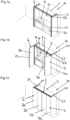
- Figures 1a, 1b and 1c show a piece of furniture 16, with a fixed furniture part 3, two furniture walls 27 and two furniture doors 2.
- These furniture doors 2 are designed as folding-sliding doors and each have a first door leaf 2a and a second door leaf 2b, the two door leaves 2a, 2b can be folded via the folding door hinges 17.
- the furniture 16 also has a receiving area 18 and two laterally arranged receiving shafts 21 or “pockets”. It is therefore provided that the furniture 16 has a receiving area 18 for receiving components of a kitchen 19 (for example electrical devices such as a stove, oven, etc.), a clothing storage device 20 (for example drawers, clothes hangers, boxes, etc.) or the like.
- a kitchen 19 for example electrical devices such as a stove, oven, etc.
- a clothing storage device 20 for example drawers, clothes hangers, boxes, etc.
- a furniture door 2 can be retracted in each of the two receiving shafts 21, which can be arranged laterally in or on the furniture 16.
- the receiving shafts 21 can therefore either be arranged on the outside of the furniture 16, or the receiving shafts 21 are formed in the furniture 16, for example by arranging an additional wall.
- the illustration shown corresponds to the parking position of the furniture doors 2 and those in Figure 1c corresponds to the closed position of the furniture doors 2.
- the second door leaf 2b is each coupled to a carriage 5, the carriage 5 being displaceable along a first guide rail 4.
- Further guide rails 14 (not visible) for guiding the furniture doors 2 are arranged in the receiving shafts 21 or, more precisely, on the furniture walls 27.
- the two receiving shafts 21 have a clear width from 10 to 30 cm and/or a height of 100 to 250 cm and/or a depth of 60 to 100 cm.
- the first guide rail 4 is therefore arranged essentially transversely to the further guide rails 14 on the furniture 16.
- a web 22 is provided, which is either part of the first guide rail 4 or is designed as a separate component.
- the movement of the furniture doors 2 between the park position and the closed position is made possible by the first guide rail 4 and the further guide rails 14.
- the furniture doors 2 can be moved into that position Figure 1b can be moved, which can be seen from the furniture door 2 shown on the left.
- the furniture doors 2 are moved along the additional guide rails 14.
- the furniture doors 2 are subsequently moved into the essentially coplanar position Figure 1c brought.
- the door leaf 2b is moved along the first guide rail 4 with the aid of the carriage 5 until the closed position of the furniture doors 2 is reached, in which the two door leaves 2a, 2b are aligned essentially coplanar.
- the same process is carried out in reverse order.
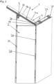
- Figure 2 shows the guide system 1, which includes the first guide rail 4 and the carriage 5.
- the first guide rail 4 consists of the two rail pieces 4a, 4b, these two rail pieces 4a, 4b being connected to one another via the connecting piece 8.
- a transfer device 23 is provided, which is connected to the first rail piece 4a of the first guide rail 4 via the connecting piece 8.
- This transfer device 23 has a control cam on its underside, so that the kinetic energy of the furniture door 2 can be used during the transition from the first guide rail 4 to the further guide rail 14 or from the further guide rail 14 to the first guide rail 4.
- this transfer device 23 is followed by the Carrier 15.
- a vertical support structure 34 is movably mounted on each of the further guide rails 14, with hinges 28 for fastening the first door leaf 2a of the furniture door 2 being arranged on this support structure 34, so that the furniture door 2 can be retracted into these receiving shafts 21. If the furniture door 2 is moved into the position in which the door leaves 2a, 2b are essentially aligned parallel to one another, then the carriage 5 is moved onto this carrier 15. The carrier 15 is further arranged on the vertical support structure 34 and thus the furniture door 2 can be moved along the further guide rail 14.
- At least one further guide rail 14 and at least one carrier 15 provided, the at least one carrier 15 being movably mounted on the at least one further guide rail 14, on or on the at least one carrier 15 of the at least one carriage 5 can be arranged, and the at least one carrier 15 can be arranged at least in some areas in the extension of the first guide rail 4.
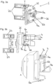
- Figure 3a shows the carriage 5 in a perspective view.
- the carriage 5 has a support profile 25 and the fitting parts 24 which are connected to the support profile 25 in an articulated manner about the vertical axis V. These fittings 24 are used to fasten the door leaves 2b.
- the rolling elements 6a, 6b and the control roller 26 are arranged on the support profile 25.
- the rolling elements 6a and the control roller 26 are rotatably mounted about a vertical axis and the rolling element 6b is rotatably mounted about a horizontal axis (this rotatable bearing relates to the mounting position of the carriage 5).
- Figure 3b shows the carriage 5 movably mounted along the first guide rail 4 in a plan view and a detailed view of the area A.
- the support profile 25 is essentially U-shaped, so that the support profile 25 can be placed on the web 22 and can also be moved along the web 22.
- the first guide rail 4 has the two running surfaces 7a, 7b, the two upper rolling elements 6a being supported on the running surface 7a and being movable along this running surface 7a.
- the rolling element 6b is supported on the running surface 7b and can be moved along this running surface 7b.
- the rolling elements 6a thus serve to absorb horizontal forces and the rolling elements 6b serve to absorb vertical forces (e.g. the weight of the furniture door 2 that can be arranged on the carriage 5 via the fitting parts 24).
- Figure 4 shows a first exemplary embodiment of the first guide rail 4, which is divided into pieces in the longitudinal direction L.
- This first guide rail 4 has the first rail piece 4a and the second rail piece 4b.
- the two rail pieces 4a, 4b are already connected to one another. It can be provided that at least one of the provided rail pieces 4a, 4b of the at least one first guide rail 4 can be adjusted in length, with the ability to be connected to further rail pieces 4a, 4b being retained.
- Figure 5 shows the first guide rail 4 consisting of the two rail pieces 4a, 4b in a perspective view and a detailed view of the area A.
- the two adapter pieces 9 can be seen here, which are inserted into the two rail pieces 4a, 4b.
- the rail pieces 4a, 4b of the at least one first guide rail 4 are designed as a hollow chamber profile, the adapter pieces 9 provided being at least partially receivable in end sections of the rail pieces 4a, 4b.
- the connecting piece 8 can be pushed between these two adapter pieces 9 and then the two screws 32 are screwed into the respective holes of the connecting piece 8 and the adapter pieces 9, so that the connecting piece 8 is screwed to the two adapter pieces 9 and at the same time a connection between the two rail pieces 4a, 4b arises.
- the rail pieces 4a, 4b of the at least one first guide rail 4 each have at least one adapter piece 9, via which the rail pieces 4a, 4b are connected to the at least a connecting piece 8 can be detachably connected, preferably via a screw and/or clamp connection.
- the adapter pieces 9 can also be designed in one piece with the respective rail piece 4a, 4b.
- at least one adapter piece 9 is in the assembled state (see Figure 4 ) is essentially hidden from the outside by the respective rail piece 4a, 4b and the at least one connecting piece 8.
- the section A1 of the running surface 7a is also formed for the rolling elements 6a of the carriage 5 and the section A2 of the running surface 7b for the rolling elements 6b of the carriage 5.
- Figure 6 shows the second rail piece 4b and the adapter piece 9 accommodated in the second rail piece 4b in a perspective view and a detailed representation of the area A.
- the two wedges K1 of the adapter piece 9 can be seen.
- Figure 7 shows the second rail piece 4b and the adapter piece 9 in a perspective view and a detailed representation of the area B.
- This illustration serves to explain the connection between the second rail piece 4b and the adapter piece 9.
- the adapter piece 9 points on the two sides on which the wedges K1 are formed each has two holes to accommodate screws. After the adapter piece 9 has been inserted into the rail piece 4b, the grub screws 29, which have an external thread, and the self-tapping screws 30 can be screwed into the respective holes. It is therefore provided that the adapter piece 9 can be detachably connected to the respective rail piece 4a, 4b, preferably via a screw and/or clamp connection. Alternatively, it would also be possible to glue the adapter pieces 9 into the respective rail pieces 4a, 4b.
- the grub screws 29 are screwed in sufficiently deep, then they hit the surface 31 so that when they are screwed in further Grub screws 29 move the adapter piece 9 in the direction of the running surfaces 7a, 7b.
- the self-tapping screws 30 since the self-tapping screws 30 are screwed into the elongated slot 35 of the rail piece 4b when screwed in and thus press the adapter piece 9 in the direction of the running surfaces 7a, 7b.
- the at least one adapter piece 9 is movable in the direction of the at least one running surface 7a, 7b for the at least one rolling element 6a, 6b of the at least one carriage 5 when it is releasably connected to the respective rail piece 4a, 4b.
- the type of screws mentioned here should not be understood as limiting. Other types of screws can also be used.
- Figure 8 shows the adapter piece 9 accommodated in the second rail piece 4b in a sectional view through the first screw plane and a detailed view of the area C.
- the adapter piece 9 has been moved in the direction of the running surfaces 7a, 7b by the screwed-in grub screws 29 and self-tapping screws 30, whereby the Wedge K1 shown on the left was pressed into the shape F of the rail section 4b, which is modeled on the wedge K1.
- the adapter piece 9 is positioned both in terms of depth and height relative to the rail section 4b.
- the positioning in the longitudinal direction L of the rail piece 4b can be done by the protruding web 36 of the adapter piece 9 (see Figure 7 ).
- Figure 9 shows two adapter pieces 9 and the connecting piece 8 in a perspective view.
- the connecting piece 8 like the rail piece 4b, has a counter-shape G1 corresponding to the wedge K1.
- Figure 10a shows further training of the Figure 9 , whereby the connecting piece 8 was partially pushed between the adapter pieces 9.
- Figure 10b shows a sectional view of the Figure 10a .
- the middle plane is M9 of the Adapter piece 9 can be seen. It is therefore provided that the at least one adapter piece 9 is designed to be mirror-symmetrical to the central plane M9.
- the wedge K1 shown on the right is not necessary for the connection in this illustration, but the adapter pieces 9 can be used universally for both ends of a rail section 4a, 4b.
- Figure 11a again shows further training Figure 10a , with the connecting piece 8 being pushed completely between the two adapter pieces 9.
- Figure 11b shows a sectional view of the Figure 11a .
- the screws 32 can then be screwed into the corresponding holes in the connecting piece 8 and the adapter pieces 9, so that the connecting piece 8 is firmly connected to the adapter pieces 9.
- the wedge K1 of the adapter piece 9 shown on the left is moved into the counterform G1 of the connecting piece 8, so that the connecting piece 8 is adjusted in height and depth.
- Figure 12a shows the representation of the Figure 11a , where the upper part of the Figure 11a is cut off. It can be seen that the adapter pieces 9 have further wedges K2, which interact with further counterforms G2 of the connecting piece 8 when the adapter pieces 9 are connected to the connecting piece 8.
- the connecting piece 8 has a central web 33, so that the adapter pieces 8 do not rest against each other when connected via the connecting piece 8.
- Figure 12b shows Figure 12a in a top view.
- the central plane M8 of the connecting piece 8 is shown.
- the at least one connecting piece 8 is designed to be mirror-symmetrical to the central plane M8.
- the rail pieces 4a, 4b of the at least one first guide rail 4 the at least one connecting piece 8 can each be positioned relative to one another via at least one positioning device K1, K2, G1, G2, the at least one positioning device having at least one wedge K1, K2 and at least one corresponding counterform G1, G2.
- Figure 13 shows a sectional view of the Figure 12b through the plane of the screws 32, with the rail pieces 4a, 4b also being shown.
- the screws 32 are screwed into the connecting piece 8 and the adapter pieces 9, these screws 32 having an external thread which cooperates with an internal thread of the respective holes in the adapter pieces 9.
- the grub screws 29, which, like the screws 32, are screwed into the holes shown at the bottom, and the self-tapping screws 30, which are screwed into the holes shown at the top, are not shown.
- the positioning device K1, K2, G1, G2 is used, on the one hand, to position the connecting pieces 8 relative to the adapter pieces 9 or to the rail pieces 4a, 4b and, on the other hand, to position the adapter pieces 9 relative to the rail pieces 4a, 4b.
- the running surfaces 7a, 7b have been completed by the sections A1, A2 of the connecting piece 8.
- the carriage 5 thus only runs over the running surfaces 7a, 7b, which are formed on the rail sections 4a, 4b, and over the sections A1, A2 of the running surfaces 7a, 7b of the connecting piece 8.
- the individual rolling elements 6a, 6b occur When the carriage 5 runs along the first guide rail 4, it does not come into direct contact with the adapter pieces 9.
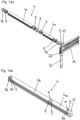
- Figures 14a and 14b show a further exemplary embodiment of the first guide rail 4.
- the further guide rail 14 can be seen, which is arranged essentially transversely to the first guide rail 4.
- the vertical support structure 34 and the support 15 arranged thereon are movably mounted on this further guide rail 14.
- the two end pieces 12, 13 are arranged at the two ends 10, 11 of the first guide rail 4, the end piece 13 additionally fulfilling the function of the transfer device 23 Figure 2 having.
- This end piece 13 is connected to the first rail piece 4a of the first guide rail 4 via the further connecting piece 8a.
- the at least one first guide rail 4 has an end piece 12, 13 at one or both ends 10, 11. Furthermore, it can be provided that at least one of the intended end pieces 13 can be detachably connected to the at least one first guide rail 4, preferably via at least one further connecting piece 8a, which is identical to the at least one connecting piece 8, via which the two rail pieces 4a, 4b of the at least a first guide rail 4 can be detachably connected.
- a guide system 1 it can also be provided that all components from which the guide system 1 can be assembled have a maximum length of 1200 mm and a maximum width of 800 mm, so that they can be arranged on a Europool pallet for shipping purposes.
Landscapes
- Engineering & Computer Science (AREA)
- Mechanical Engineering (AREA)
- Life Sciences & Earth Sciences (AREA)
- Sustainable Development (AREA)
- Support Devices For Sliding Doors (AREA)
- Extensible Doors And Revolving Doors (AREA)
- Cabinets, Racks, Or The Like Of Rigid Construction (AREA)
Description
- Die vorliegende Erfindung betrifft ein Führungssystem zur Führung einer Möbeltüre, insbesondere einer Falttür oder Falt-Schiebe-Tür, relativ zu einem feststehenden Möbelteil mit den Merkmalen des Oberbegriffs des Anspruchs 1 und ein Möbel mit wenigstens einem solchen Führungssystem.
- Bereits bekannt sind Führungssysteme zur Führung einer Möbeltüre relativ zu einem feststehenden Möbelteil, wobei diese Führungssysteme in Abhängigkeit von den jeweiligen Maßen des Möbels und der zu führenden Möbeltüren eine dementsprechend lange Führungsschiene aufweisen.
- Dadurch wird allerdings der Transport erschwert, da viele verschiedene Führungsschienen für unterschiedliche Möbel und Möbeltüren transportiert werden müssen. Zusätzlich wird auch die Montage erschwert, da die die Montagearbeiten durchführende Person gegebenenfalls sehr lange Führungsschienen am Möbel montieren muss. Außerdem sind derartige Führungssysteme sehr unflexibel, da jeweils Führungsschienen bereitgestellt werden müssen, die den jeweiligen Maßen der Möbel und der Möbeltüren entsprechen.
- Ausgehend hiervon könnte die Führungsschiene des Führungssystems auch gestückelt werden. Werden die gestückelten Führungsschienenteile wieder zusammengebaut, dann werden beim Laufen des Laufwagens entlang der zusammengebauten Führungsschiene hörbare Geräusche verursacht, wobei zusätzlich ein unruhiges Laufen des Laufwagens resultiert.
- Die
EP1013865A2 offenbart eine gestückelte Führungsschiene. - Aufgabe der Erfindung ist es wenigstens einen der vorbeschriebenen Nachteile zu vermeiden und ein gegenüber dem Stand der Technik verbessertes Führungssystem und ein verbessertes Möbel anzugeben.
- Diese Aufgaben werden durch die Merkmale der unabhängigen Ansprüche 1 und 12 gelöst.
- Vorteilhafte Ausführungsformen der Erfindung sind in den abhängigen Ansprüchen definiert.
- Eine wesentliche Idee im Hinblick auf das erfindungsgemäße Führungssystem ist also, dass die wenigstens eine erste Führungsschiene in Längsrichtung aus zumindest einem ersten und einem zweiten Schienenstück zusammengesetzt ist, wobei die beiden Schienenstücke über wenigstens ein Verbindungsstück lösbar verbindbar sind, an welchem ein Abschnitt der wenigstens einen Lauffläche für den wenigstens einen Wälzkörper des wenigstens einen Laufwagens ausgebildet ist. Dadurch wird ein ruhigeres Laufen des Laufwagens entlang der wenigstens einen Lauffläche sichergestellt.
- Damit die Verbindung zwischen den einzelnen Schienenstücken verbessert wird und hörbare Geräusche weitgehend vermieden werden ist vorgesehen, dass die Schienenstücke der wenigstens einen ersten Führungsschiene mit dem wenigstens einen Verbindungsstück jeweils über wenigstens eine Positioniervorrichtung relativ zueinander positionierbar sind, wobei die wenigstens eine Positioniervorrichtung wenigstens einen Keil und wenigstens eine korrespondierende Gegenform aufweist.
- Durch die wenigstens eine Positioniervorrichtung ist es möglich, dass der Übergang zwischen den Schienenstücken im Wesentlichen stufenlos erfolgt und nur Toleranzen des Materials eine Rolle spielen. Durch die Verbindung selber ergeben sich keine zusätzlichen Niveauunterschiede zwischen den Schienenstücken.
- Wie eingangs erwähnt wird auch Schutz begehrt für ein Möbel mit wenigstens einer Möbeltüre, insbesondere einer Falttür oder Falt-Schiebe-Tür, wenigstens einem feststehenden Möbelteil und wenigstens einem Führungssystem zur Führung der wenigstens einen Möbeltüre relativ zu dem wenigstens einen feststehenden Möbelteil.
- Weitere Vorteile und Einzelheiten der Erfindung ergeben sich anhand der Figuren und der dazugehörigen Figurenbeschreibung. Dabei zeigen:
- Figur 1a-1c
- perspektivische Ansichten eines Möbels mit zwei Möbeltüren, die in unterschiedlichen Positionen dargestellt sind,
- Figur 2
- ein Führungssystem und eine Falt-Schiebe-Tür in einer perspektivischen Ansicht,
- Figur 3a-3b
- den Laufwagen in einer perspektivischen Ansicht, einer Draufsicht und eine Detaildarstellung der Draufsicht,
- Figur 4
- ein erstes Ausführungsbeispiel der gestückelten ersten Führungsschiene in einer perspektivischen Ansicht,
- Figur 5
- die gestückelte erste Führungsschiene in einer perspektivischen Ansicht,
- Figur 6
- ein Schienenstück der ersten Führungsschiene in einer perspektivischen Ansicht und eine Detaildarstellung hiervon,
- Figur 7
- ein Schienenstück der ersten Führungsschiene und das Adapterstück in einer perspektivischen Ansicht und eine Detaildarstellung hiervon,
- Figur 8
- das Schienenstück der ersten Führungsschiene in einer perspektivischen geschnittenen Ansicht und eine Detaildarstellung hiervon,
- Figur 9
- zwei Adapterstücke und das Verbindungsstück in einer perspektivischen Ansicht,
- Figur 10a-10b
- zwei Adapterstücke und das mit den Adapterstücken teilweise verbundene Verbindungsstück in einer perspektivischen Ansicht und eine Schnittdarstellung hiervon,
- Figur 11a-11b
- zwei Adapterstücke und das mit den Adapterstücken verbundene Verbindungsstück in einer perspektivischen Ansicht und eine Schnittdarstellung hiervon,
- Figur 12a-12b
- einen Schnitt der
Figur 11a in einer perspektivischen Ansicht und einer Draufsicht, - Figur 13
- eine weitere Schnittdarstellung der
Figur 11a mit den Schienenstücken, und - Figur 14a-14b
- ein weiteres Ausführungsbeispiel einer gestückelten ersten Führungsschiene in perspektivischen Ansichten.
-
Figuren 1a, 1b und 1c zeigen ein Möbel 16, mit einem feststehenden Möbelteil 3, zwei Möbelwänden 27 und zwei Möbeltüren 2. Diese Möbeltüren 2 sind als Falt-Schiebe-Türen ausgebildet und weisen je ein erstes Türblatt 2a und ein zweites Türblatt 2b auf, wobei die beiden Türblätter 2a, 2b über die Falttürscharniere 17 faltbar sind. Das Möbel 16 weist weiterhin einen Aufnahmebereich 18 und zwei seitlich angeordnete Aufnahmeschächte 21 bzw. "Pockets" auf. Es ist also vorgesehen, dass das Möbel 16 einen Aufnahmebereich 18 zur Aufnahme von Bestandteilen einer Küche 19 (beispielsweise elektrische Geräte wie Herd, Backofen, usw.), einer Kleideraufbewahrungsvorrichtung 20 (beispielsweise Schubladen, Kleiderbügel, Kästchen, usw.) oder dergleichen aufweist. - In den beiden Aufnahmeschächten 21, welche seitlich im oder am Möbel 16 angeordnet sein können, ist je eine Möbeltüre 2 versenkbar. Die Aufnahmeschächte 21 können also entweder von außen am Möbel 16 angeordnet werden, oder aber die Aufnahmeschächte 21 werden im Möbel 16 ausgebildet, beispielsweise durch die Anordnung einer zusätzlichen Wand.
- Die in
Figur 1a gezeigte Darstellung entspricht dabei der Parkstellung der Möbeltüren 2 und jene inFigur 1c entspricht der Schließstellung der Möbeltüren 2. Das zweite Türblatt 2b ist jeweils mit einem Laufwagen 5 gekoppelt, wobei der Laufwagen 5 entlang einer ersten Führungsschiene 4 verschiebbar ist. In den Aufnahmeschächten 21 bzw. genauer gesagt an den Möbelwänden 27 sind weitere Führungsschienen 14 (nicht ersichtlich) zur Führung der Möbeltüren 2 angeordnet. Die beiden Aufnahmeschächte 21 weisen dabei eine lichte Breite von 10 bis 30 cm und/oder eine Höhe von 100 bis 250 cm und/oder eine Tiefe von 60 bis 100 cm auf. Die erste Führungsschiene 4 ist also im Wesentlichen quer zu den weiteren Führungsschienen 14 am Möbel 16 angeordnet. - Zudem ist ein Steg 22 vorgesehen, welcher entweder Teil der ersten Führungsschiene 4 oder als davon gesondertes Bauteil ausgeführt ist. Durch die erste Führungsschiene 4 und die weiteren Führungsschienen 14 wird also die Bewegung der Möbeltüren 2 zwischen der Parkstellung und der Schließstellung ermöglicht. Ausgehend von der Parkstellung der Möbeltüren 2, in welcher die Türblätter 2a, 2b im Wesentlichen parallel zueinander ausgerichtet sind, können die Möbeltüren 2 also in jene Stellung der
Figur 1b bewegt werden, die anhand der links dargestellten Möbeltüre 2 ersichtlich ist. Hierbei werden die Möbeltüren 2 entlang der weiteren Führungsschienen 14 verschoben. In weiterer Folge werden die Möbeltüren 2 in die im Wesentlichen koplanare Stellung gemäßFigur 1c gebracht. Dazu wird jeweils das Türblatt 2b mit Hilfe des Laufwagens 5 entlang der ersten Führungsschiene 4 verschoben, bis die Schließstellung der Möbeltüren 2 erreicht ist, in welcher die beiden Türblätter 2a, 2b im Wesentlichen koplanar ausgerichtet sind. Zur Bewegung der Möbeltüren 2 ausgehend von ihrer Schließstellung in ihre Parkstellung wird derselbe Ablauf in umgekehrter Reihenfolge durchlaufen. -
Figur 2 zeigt das Führungssystem 1, welches die erste Führungsschiene 4 und den Laufwagen 5 umfasst. Die erste Führungsschiene 4 besteht dabei aus den beiden Schienenstücken 4a, 4b, wobei diese beiden Schienenstücke 4a, 4b über das Verbindungsstück 8 miteinander verbunden sind. Des Weiteren ist eine Transfervorrichtung 23 vorgesehen, welche mit dem ersten Schienenstück 4a der ersten Führungsschiene 4 über das Verbindungsstück 8 verbunden ist. Diese Transfervorrichtung 23 weist an ihrer Unterseite eine Steuerkurve auf, sodass die Bewegungsenergie der Möbeltüre 2 beim Übergang von der ersten Führungsschiene 4 auf die weitere Führungsschiene 14 bzw. von der weiteren Führungsschiene 14 auf die erste Führungsschiene 4 genutzt werden kann. In der gezeigten Darstellung schließt sich an diese Transfervorrichtung 23 der Träger 15 an. Zudem ist an den weiteren Führungsschienen 14 je eine vertikale Trägerstruktur 34 bewegbar gelagert, wobei an dieser Trägerstruktur 34 Scharniere 28 zur Befestigung des ersten Türblattes 2a der Möbeltüre 2 angeordnet sind, sodass die Möbeltüre 2 in diesen Aufnahmeschächten 21 versenkbar sind. Wird die Möbeltüre 2 in jene Stellung bewegt, in der die Türblätter 2a, 2b im Wesentlichen parallel zueinander ausgerichtet sind, dann wird der Laufwagen 5 auf diesen Träger 15 verschoben. Der Träger 15 ist weiterhin an der vertikalen Trägerstruktur 34 angeordnet und somit kann die Möbeltüre 2 entlang der weiteren Führungsschiene 14 verschoben werden. Es sind also wenigstens eine weitere Führungsschiene 14 und wenigstens ein Träger 15 vorgesehen, wobei der wenigstens eine Träger 15 an der wenigstens einen weiteren Führungsschiene 14 verfahrbar gelagert ist, auf oder an dem wenigstens einen Träger 15 der wenigstens eine Laufwagen 5 anordenbar ist, und der wenigstens eine Träger 15 zumindest bereichsweise in der Verlängerung zur ersten Führungsschiene 4 anordenbar ist. -
Figur 3a zeigt den Laufwagen 5 in einer perspektivischen Ansicht. Der Laufwagen 5 weist ein Trägerprofil 25 und die mit dem Trägerprofil 25 um die vertikale Achse V gelenkig verbundenen Beschlagteile 24 auf. Diese Beschlagteile 24 dienen zur Befestigung der Türblätter 2b. Darüber hinaus sind an dem Trägerprofil 25 die Wälzkörper 6a, 6b und die Steuerrolle 26 angeordnet. Dabei sind die Wälzkörper 6a und die Steuerrolle 26 um eine vertikale Achse drehbar gelagert und der Wälzkörper 6b ist um eine horizontale Achse drehbar gelagert (diese drehbare Lagerung bezieht sich auf die Montagelage des Laufwagens 5).Figur 3b zeigt den entlang der ersten Führungsschiene 4 bewegbar gelagerten Laufwagen 5 in einer Draufsicht und eine detaillierte Ansicht des Bereichs A. Dabei ist ersichtlich, dass das Trägerprofil 25 im Wesentlichen U-förmig ausgebildet ist, sodass das Trägerprofil 25 auf den Steg 22 aufgesetzt werden kann und auch entlang des Steges 22 verschiebbar ist. Die erste Führungsschiene 4 weist die beiden Laufflächen 7a, 7b auf, wobei sich die beiden oberen Wälzkörper 6a an der Lauffläche 7a abstützen und entlang dieser Lauffläche 7a verfahrbar sind. - Hingegen stützt sich der Wälzkörper 6b an der Lauffläche 7b ab und ist entlang dieser Lauffläche 7b verfahrbar. Somit dienen die Wälzkörper 6a zur Aufnahme horizontaler Kräfte und der Wälzkörper 6b dient zur Aufnahme vertikaler Kräfte (z.B. die Gewichtskraft der an dem Laufwagen 5 über die Beschlagteile 24 anordenbaren Möbeltüre 2).
-
Figur 4 zeigt ein erstes Ausführungsbeispiel der ersten Führungsschiene 4, welche in Längsrichtung L gestückelt ist. Diese erste Führungsschiene 4 weist das erste Schienenstück 4a und das zweite Schienenstück 4b auf. In dieser Darstellung sind die beiden Schienenstücke 4a, 4b bereits miteinander verbunden. Dabei kann vorgesehen sein, dass wenigstens eines der vorgesehenen Schienenstücke 4a, 4b der wenigstens einen ersten Führungsschiene 4 in seiner Länge anpassbar ist, wobei die Verbindbarkeit mit weiteren Schienenstücken 4a, 4b erhalten bleibt. -
Figur 5 zeigt die aus den beiden Schienenstücken 4a, 4b bestehende erste Führungsschiene 4 in einer perspektivischen Ansicht und eine detaillierte Ansicht des Bereichs A. Hierbei sind die beiden Adapterstücke 9 ersichtlich, welche in die beiden Schienenstücke 4a, 4b eingesteckt sind. Die Schienenstücke 4a, 4b der wenigstens einen ersten Führungsschiene 4 sind hierbei als Hohlkammerprofil ausgebildet, wobei die vorgesehenen Adapterstücke 9 zumindest bereichsweise in Endabschnitten der Schienenstücke 4a, 4b aufnehmbar sind. Das Verbindungsstück 8 kann zwischen diese beiden Adapterstücke 9 hineingeschoben werden und anschließend werden die beiden Schrauben 32 in die jeweiligen Löcher des Verbindungsstücks 8 und der Adapterstücke 9 eingeschraubt, sodass das Verbindungsstück 8 mit den beiden Adapterstücken 9 verschraubt wird und gleichzeitig eine Verbindung zwischen den beiden Schienenstücken 4a, 4b entsteht. Es ist also vorgesehen, dass die Schienenstücke 4a, 4b der wenigstens einen ersten Führungsschiene 4 jeweils zumindest ein Adapterstück 9 aufweisen, über welches die Schienenstücke 4a, 4b mit dem wenigstens einen Verbindungsstück 8 lösbar verbindbar sind, vorzugsweise über eine Schraub- und/oder Klemmverbindung. - An dieser Stelle wird darauf hingewiesen, dass die Adapterstücke 9 auch einstückig mit dem jeweiligen Schienenstück 4a, 4b ausgebildet sein können. In diesem Zusammenhang wird außerdem noch angemerkt, dass das jeweils zumindest eine Adapterstück 9 im montierten Zustand (siehe
Figur 4 ) von dem jeweiligen Schienenstück 4a, 4b und dem wenigstens einen Verbindungsstück 8 nach außen hin im Wesentlichen verdeckt ist. An dem Verbindungsstück 8 ist zudem der Abschnitt A1 der Lauffläche 7a für die Wälzkörper 6a des Laufwagens 5 und der Abschnitt A2 der Lauffläche 7b für den Wälzkörper 6b des Laufwagens 5 ausgebildet. -
Figur 6 zeigt das zweite Schienenstück 4b und das im zweiten Schienenstück 4b aufgenommene Adapterstück 9 in einer perspektivischen Ansicht und eine Detaildarstellung des Bereichs A. Dabei sind die beiden Keile K1 des Adapterstücks 9 erkennbar. -
Figur 7 zeigt das zweite Schienenstück 4b und das Adapterstück 9 in einer perspektivischen Ansicht und eine Detaildarstellung des Bereichs B. Diese Darstellung dient der Erklärung der Verbindung zwischen zweitem Schienenstück 4b und Adapterstück 9. Das Adapterstück 9 weist an den beiden Seiten, an denen die Keile K1 ausgebildet sind, jeweils zwei Löcher zur Aufnahme von Schrauben auf. Nachdem das Adapterstück 9 in das Schienenstück 4b eingesteckt wurde, können die Madenschrauben 29, welche ein Außengewinde aufweisen, und die selbstschneidenden Schrauben 30 in die jeweiligen Löcher eingeschraubt werden. Es ist also vorgesehen, dass das Adapterstück 9 lösbar mit dem jeweiligen Schienenstück 4a, 4b verbindbar ist, vorzugsweise über eine Schraub- und/oder Klemmverbindung. Alternativ wäre es auch möglich, die Adapterstücke 9 in die jeweiligen Schienenstücke 4a, 4b einzukleben. Werden die Madenschrauben 29 ausreichend tief eingeschraubt, dann treffen diese auf die Fläche 31, sodass beim weiteren Einschrauben der Madenschrauben 29 das Adapterstück 9 in Richtung der Laufflächen 7a, 7b bewegt wird. Ähnliches gilt für die selbstschneidenden Schrauben 30, da die selbstschneidenden Schrauben 30 beim Einschrauben in den länglichen Schlitz 35 des Schienenstücks 4b eingeschraubt werden und somit das Adapterstück 9 in Richtung der Laufflächen 7a, 7b drücken. Es kann also vorgesehen sein, dass das jeweils zumindest eine Adapterstück 9 bei der lösbaren Verbindung mit dem jeweiligen Schienenstück 4a, 4b in Richtung der wenigstens einen Lauffläche 7a, 7b für den wenigstens einen Wälzkörper 6a, 6b des wenigstens einen Laufwagens 5 bewegbar ist. Die Art der hierbei erwähnten Schrauben soll allerdings nicht einschränkend verstanden werden. Es sind auch andere Schraubenarten verwendbar. -
Figur 8 zeigt das in das zweite Schienenstück 4b aufgenommene Adapterstück 9 in einer Schnittdarstellung durch die erste Schraubenebene und eine Detaildarstellung des Bereichs C. Durch die eingeschraubten Madenschrauben 29 und selbstschneidenden Schrauben 30 ist das Adapterstück 9 in Richtung der Laufflächen 7a, 7b bewegt worden, wobei auch der links dargestellte Keil K1 in die dem Keil K1 nachempfundene Form F des Schienenstücks 4b eingedrückt wurde. Durch den Keil K1, die dem Keil K1 nachempfundene Form F des Schienenstücks 4b, die Madenschrauben 29 und die selbstschneidenden Schrauben 30 wird also das Adapterstück 9 sowohl tiefenmäßig als auch höhenmäßig relativ zum Schienenstück 4b positioniert. Die Positionierung in Längsrichtung L des Schienenstücks 4b kann durch den überstehenden Steg 36 des Adapterstücks 9 erfolgen (sieheFigur 7 ). -
Figur 9 zeigt zwei Adapterstücke 9 und das Verbindungsstück 8 in einer perspektivischen Ansicht. Das Verbindungsstück 8 weist wie das Schienenstück 4b eine dem Keil K1 entsprechende Gegenform G1 auf. -
Figur 10a zeigt eine Weiterbildung derFigur 9 , wobei das Verbindungsstück 8 teilweise zwischen die Adapterstücke 9 hineingeschoben wurde.Figur 10b zeigt eine Schnittdarstellung derFigur 10a . Dabei ist die Mittelebene M9 des Adapterstücks 9 ersichtlich. Es ist also vorgesehen, dass das jeweils zumindest eine Adapterstück 9 spiegelsymmetrisch zu der Mittelebene M9 ausgebildet ist. Der rechts dargestellte Keil K1 ist in dieser Darstellung für die Verbindung nicht notwendig, allerdings können die Adapterstücke 9 universell für beide Enden eines Schienenstücks 4a, 4b verwendet werden. -
Figur 11a zeigt wiederum eine Weiterbildung derFigur 10a , wobei das Verbindungsstück 8 vollständig zwischen die beiden Adapterstücke 9 hineingeschoben wurde.Figur 11b zeigt eine Schnittdarstellung derFigur 11a . In dieser Darstellung können sodann die Schrauben 32 in die entsprechenden Löcher des Verbindungsstücks 8 und der Adapterstücke 9 eingeschraubt werden, sodass das Verbindungsstück 8 fest mit den Adapterstücken 9 verbunden ist. Dadurch wird der links dargestellte Keil K1 des Adapterstücks 9 in die Gegenform G1 des Verbindungsstücks 8 hineinbewegt, sodass das Verbindungsstück 8 höhen und tiefenmäßig adjustiert ist. -
Figur 12a zeigt die Darstellung derFigur 11a , wobei der obere Teil derFigur 11a abgeschnitten ist. Dabei ist ersichtlich, dass die Adapterstücke 9 weitere Keile K2 aufweisen, die bei der Verbindung der Adapterstücke 9 mit dem Verbindungsstück 8 mit weiteren Gegenformen G2 des Verbindungsstücks 8 zusammenwirken. Zudem weist das Verbindungsstück 8 einen Mittelsteg 33 auf, sodass die Adapterstücke 8 bei der Verbindung über das Verbindungsstück 8 nicht aneinander anliegen. -
Figur 12b zeigtFigur 12a in einer Draufsicht. Dabei ist die Mittelebene M8 des Verbindungsstücks 8 eingezeichnet. Es ist also vorgesehen, dass das wenigstens eine Verbindungsstück 8 spiegelsymmetrisch zu der Mittelebene M8 ausgebildet ist. Beim Einschrauben der Schrauben 32 in die jeweiligen Löcher des Verbindungsstücks 8 und der Adapterstücke 9 werden die Gegenformen G2 gegen die Keile K2 gedrückt, sodass die Adapterstücke 9 relativ zueinander bewegt werden. Es ist also vorgesehen, dass die Schienenstücke 4a, 4b der wenigstens einen ersten Führungsschiene 4 mit dem wenigstens einen Verbindungsstück 8 jeweils über wenigstens eine Positioniervorrichtung K1, K2, G1, G2 relativ zueinander positionierbar sind, wobei die wenigstens eine Positioniervorrichtung wenigstens einen Keil K1, K2 und wenigstens eine korrespondierende Gegenform G1, G2 aufweist. -
Figur 13 zeigt eine Schnittdarstellung derFigur 12b durch die Ebene der Schrauben 32, wobei zusätzlich die Schienenstücke 4a, 4b dargestellt sind. Außerdem sind die Schrauben 32 in das Verbindungsstück 8 und die Adapterstücke 9 eingeschraubt, wobei diese Schrauben 32 ein Außengewinde aufweisen, welches mit einem Innengewinde der jeweiligen Löcher der Adapterstücke 9 zusammenwirkt. Die Madenschrauben 29, welche wie die Schrauben 32 in die in Darstellung unteren Löcher eingeschraubt werden, und die selbstschneidenden Schrauben 30, welche in die in Darstellung oberen Löcher eingeschraubt werden, sind nicht dargestellt. Die Positioniervorrichtung K1, K2, G1, G2 dient also einerseits zur Positionierung der Verbindungsstücke 8 relativ zu den Adapterstücken 9 bzw. zu den Schienenstücken 4a, 4b und andererseits zur Positionierung der Adapterstücke 9 relativ zu den Schienenstücken 4a, 4b. Nachdem die jeweilige Positionierung erfolgt ist, sind die Laufflächen 7a, 7b durch die Abschnitte A1, A2 des Verbindungsstücks 8 vervollständigt worden. Somit läuft der Laufwagen 5 nur über die Laufflächen 7a, 7b, die auf den Schienenstücken 4a, 4b ausgebildet sind, und über die Abschnitte A1, A2 der Laufflächen 7a, 7b des Verbindungsstücks 8. Mit anderen Worten treten die einzelnen Wälzkörper 6a, 6b beim Laufen des Laufwagens 5 entlang der ersten Führungsschiene 4 nicht unmittelbar mit den Adapterstücken 9 in Kontakt. -
Figur 14a und 14b zeigen ein weiteres Ausführungsbeispiel der ersten Führungsschiene 4. Dabei ist die weitere Führungsschiene 14 ersichtlich, welche im Wesentlichen quer zur ersten Führungsschiene 4 angeordnet ist. Auf dieser weiteren Führungsschiene 14 ist die vertikale Trägerstruktur 34 und der daran angeordnete Träger 15 verfahrbar gelagert. Zudem ist ein Scharnier 28 an der Trägerstruktur 34 angeordnet, welches zur Befestigung des ersten Türblattes 2a dient. An den beiden Enden 10, 11 der ersten Führungsschiene 4 sind dabei die beiden Abschlussstücke 12, 13 angeordnet, wobei das Abschlussstück 13 zusätzlich die Funktion der Transfervorrichtung 23 gemäßFigur 2 aufweist. Dieses Abschlussstück 13 ist dabei über das weitere Verbindungsstück 8a mit dem ersten Schienenstück 4a der ersten Führungsschiene 4 verbunden. - Es kann also vorgesehen sein, dass die wenigstens eine erste Führungsschiene 4 an einem oder an beiden Enden 10, 11 ein Abschlussstück 12, 13 aufweist. Weiterhin kann vorgesehen sein, dass wenigstens eines der vorgesehenen Abschlusstücke 13 lösbar mit der wenigstens einen ersten Führungsschiene 4 verbindbar ist, vorzugsweise über wenigstens ein weiteres Verbindungsstück 8a, welches identisch zu dem wenigstens einen Verbindungsstück 8, über welches die beiden Schienenstücke 4a, 4b der wenigstens einen ersten Führungsschiene 4 lösbar verbindbar sind, ausgebildet ist.
- Bei einem Führungssystem 1 kann außerdem vorgesehen sein, dass alle Bestandteile, aus denen das Führungssystem 1 zusammensetzbar ist, eine maximale Länge von 1200 mm und eine maximale Breite von 800 mm aufweisen, so dass sie zu Versandzwecken auf einer Europoolpalette anordenbar sind.
-
- 1
- Führungssystem
- 2
- Möbeltüre
- 2a
- erstes Türblatt
- 2b
- zweites Türblatt
- 3
- feststehendes Möbelteil
- 4
- erste Führungsschiene
- 4a
- erstes Schienenstück
- 4b
- zweites Schienenstück
- 5
- Laufwagen
- 6a, 6b
- Wälzkörper
- 7a, 7b
- Lauffläche
- 8
- Verbindungsstück
- 8a
- weiteres Verbindungsstück
- 9
- Adapterstück
- 10, 11
- Enden der ersten Führungsschiene
- 12, 13
- Abschlussstück
- 14
- weitere Führungsschiene
- 15
- Träger
- 16
- Möbel
- 17
- Falttürscharniere
- 18
- Aufnahmebereich
- 19
- Bestandteile einer Küche
- 20
- Kleideraufbewahrungsvorrichtung
- 21
- Aufnahmeschacht
- 22
- Steg
- 23
- Transfervorrichtung
- 24
- Beschlagteil
- 25
- Trägerprofil
- 26
- Steuerrolle
- 27
- Möbelwand
- 28
- Scharniere
- 29
- Madenschrauben
- 30
- selbstschneidende Schrauben
- 31
- Fläche
- 32
- Schrauben
- 33
- Mittelsteg
- 34
- vertikale Trägerstruktur
- 35
- länglicher Schlitz
- 36
- überstehender Steg
- A1
- Abschnitt der Lauffläche 7a
- A2
- Abschnitt der Lauffläche 7b
- L
- Längsrichtung
- K1
- Keil
- K2
- Keil
- G1
- Gegenform
- G2
- Gegenform
- M8
- Mittelebene
- M9
- Mittelebene
- V
- vertikale Achse
- F
- dem Keil K1 nachempfundene Form der Schienenstücke
Claims (12)
- Führungssystem (1) zur Führung einer Möbeltüre (2), insbesondere einer Falttür oder Falt-Schiebe-Tür, relativ zu einem feststehenden Möbelteil (3), mit wenigstens einer ersten Führungsschiene (4) und wenigstens einem Laufwagen (5), welcher mit der Möbeltüre (2) verbindbar ist und welcher wenigstens einen Wälzkörper (6a, 6b) aufweist, über den der wenigstens eine Laufwagen (5) an der wenigstens einen ersten Führungsschiene (4) verfahrbar gelagert ist, wobei die wenigstens eine erste Führungsschiene (4) wenigstens eine Lauffläche (7a, 7b) für den wenigstens einen Wälzkörper (6a, 6b) des wenigstens einen Laufwagens (5) aufweist, wobei die wenigstens eine erste Führungsschiene (4) in Längsrichtung (L) aus zumindest einem ersten (4a) und einem zweiten Schienenstück (4b) zusammengesetzt ist, wobei die beiden Schienenstücke (4a, 4b) über wenigstens ein Verbindungsstück (8) lösbar verbindbar sind, an welchem ein Abschnitt (A1, A2) der wenigstens einen Lauffläche (7a, 7b) für den wenigstens einen Wälzkörper (6a, 6b) des wenigstens einen Laufwagens (5) ausgebildet ist, wobei die Schienenstücke (4a, 4b) der wenigstens einen ersten Führungsschiene (4) mit dem wenigstens einen Verbindungsstück (8) jeweils über wenigstens eine Positioniervorrichtung (K1, K2, G1, G2) relativ zueinander positionierbar sind, wobei die wenigstens eine Positioniervorrichtung (K1, K2, G1, G2) wenigstens einen Keil (K1, K2) und wenigstens eine korrespondierende Gegenform (G1, G2) aufweist, und die Schienenstücke (4a, 4b) der wenigstens einen ersten Führungsschiene (4) jeweils zumindest ein Adapterstück (9) aufweisen, über welches die Schienenstücke (4a, 4b) mit dem wenigstens einen Verbindungsstück (8) lösbar verbindbar sind, vorzugsweise über eine Schraub- und/oder Klemmverbindung, wobei die zumindest einen Adapterstücke (9) den wenigstens einen Keil (K1) aufweisen, und wobei das wenigstens eine Verbindungsstück (8) spiegelsymmetrisch zu einer Mittelebene (M8) ausgebildet ist, dadurch gekennzeichnet, dass die zumindest einen Adapterstücke (9) weitere Keile (K2) aufweisen, die bei der Verbindung der zumindest einen Adapterstücke (9) mit dem wenigstens einen Verbindungsstück (8) mit weiteren Gegenformen (G2) des wenigstens einen Verbindungsstücks (8) zusammenwirken, und dass das wenigstens eine Verbindungsstück (8) einen Mittelsteg (33) aufweist, sodass die zumindest einen Adapterstücke (9) bei der Verbindung über das wenigstens eine Verbindungsstück (8) nicht aneinander anliegen.
- Führungssystem (1) nach Anspruch 1, wobei das jeweils zumindest eine Adapterstück (9) spiegelsymmetrisch zu einer Mittelebene (M9) ausgebildet ist.
- Führungssystem (1) nach einem der Ansprüche 1 bis 2, wobei das jeweils zumindest eine Adapterstück (9) lösbar mit dem jeweiligen Schienenstück (4a, 4b) verbindbar ist, vorzugsweise über eine Schraub- und/oder Klemmverbindung.
- Führungssystem (1) nach Anspruch 3, wobei das jeweils zumindest eine Adapterstück (9) bei der lösbaren Verbindung mit dem jeweiligen Schienenstück (4a, 4b) in Richtung der wenigstens einen Lauffläche (7a, 7b) für den wenigstens einen Wälzkörper (6a, 6b) des wenigstens einen Laufwagens (5) bewegbar ist.
- Führungssystem (1) nach einem der Ansprüche 1 bis 4, wobei das jeweils zumindest eine Adapterstück (9) im montierten Zustand von dem jeweiligen Schienenstück (4a, 4b) und dem wenigstens einen Verbindungsstück (8) nach außen hin im Wesentlichen verdeckt ist.
- Führungssystem (1) nach einem der Ansprüche 1 bis 5, wobei die Schienenstücke (4a, 4b) der wenigstens einen ersten Führungsschiene (4) als Hohlkammerprofil ausgebildet sind, vorzugsweise wobei die vorgesehenen Adapterstücke (9) zumindest bereichsweise in Endabschnitten der Schienenstücke (4a, 4b) aufnehmbar sind.
- Führungssystem (1) nach einem der Ansprüche 1 bis 6, wobei wenigstens eines der vorgesehenen Schienenstücke (4a, 4b) der wenigstens einen ersten Führungsschiene (4) in seiner Länge anpassbar ist, wobei die Verbindbarkeit mit weiteren Schienenstücken (4a, 4b) erhalten bleibt.
- Führungssystem (1) nach einem der Ansprüche 1 bis 7, wobei alle Bestandteile, aus denen das Führungssystem (1) zusammensetzbar ist, eine maximale Länge von 1200 mm und eine maximale Breite von 800 mm aufweisen, so dass sie zu Versandzwecken auf einer Europoolpalette anordenbar sind.
- Führungssystem (1) nach einem der Ansprüche 1 bis 8, wobei die wenigstens eine erste Führungsschiene (4) an einem oder an beiden Enden (10, 11) ein Abschlussstück (12, 13) aufweist.
- Führungssystem (1) nach Anspruch 9, wobei wenigstens eines der vorgesehenen Abschlusstücke (12, 13) lösbar mit der wenigstens einen ersten Führungsschiene (4) verbindbar ist, vorzugsweise über wenigstens ein weiteres Verbindungsstück (8a), welches identisch zu dem wenigstens einen Verbindungsstück (8), über welches die beiden Schienenstücke (4a, 4b) der wenigstens einen ersten Führungsschiene (4) lösbar verbindbar sind, ausgebildet ist.
- Führungssystem (1) nach einem der Ansprüche 1 bis 10, wobei wenigstens eine weitere Führungsschiene (14) und wenigstens ein Träger (15) vorgesehen sind, wobei der wenigstens eine Träger (15) an der wenigstens einen weiteren Führungsschiene (14) verfahrbar gelagert ist, auf oder an dem wenigstens einen Träger (15) der wenigstens eine Laufwagen (5) anordenbar ist, und der wenigstens eine Träger (15) zumindest bereichsweise in der Verlängerung zur ersten Führungsschiene (4) anordenbar ist.
- Möbel (16) mit wenigstens einer Möbeltüre (2), insbesondere einer Falttür oder Falt-Schiebe-Tür, wenigstens einem feststehenden Möbelteil (3) und wenigstens einem Führungssystem (1) nach einem der Ansprüche 1 bis 11 zur Führung der wenigstens einen Möbeltüre (2) relativ zu dem wenigstens einen feststehenden Möbelteil (3).
Applications Claiming Priority (2)
| Application Number | Priority Date | Filing Date | Title |
|---|---|---|---|
| ATA50394/2017A AT519905B1 (de) | 2017-05-11 | 2017-05-11 | Führungssystem zur Führung einer Möbeltüre |
| PCT/AT2018/000040 WO2018204952A1 (de) | 2017-05-11 | 2018-05-04 | Führungssystem zur führung einer möbeltüre |
Publications (2)
| Publication Number | Publication Date |
|---|---|
| EP3622150A1 EP3622150A1 (de) | 2020-03-18 |
| EP3622150B1 true EP3622150B1 (de) | 2024-03-27 |
Family
ID=62554906
Family Applications (1)
| Application Number | Title | Priority Date | Filing Date |
|---|---|---|---|
| EP18729542.3A Active EP3622150B1 (de) | 2017-05-11 | 2018-05-04 | Führungssystem zur führung einer möbeltüre |
Country Status (8)
| Country | Link |
|---|---|
| US (1) | US11098512B2 (de) |
| EP (1) | EP3622150B1 (de) |
| JP (1) | JP6882526B2 (de) |
| CN (1) | CN110621840B (de) |
| AT (1) | AT519905B1 (de) |
| ES (1) | ES2977601T3 (de) |
| TW (1) | TWI659711B (de) |
| WO (1) | WO2018204952A1 (de) |
Families Citing this family (16)
| Publication number | Priority date | Publication date | Assignee | Title |
|---|---|---|---|---|
| AT519374B1 (de) * | 2017-01-13 | 2018-06-15 | Blum Gmbh Julius | Führungssystem zur Führung eines bewegbar gelagerten Möbelteiles |
| AT519514B1 (de) * | 2017-01-13 | 2021-07-15 | Blum Gmbh Julius | Führungssystem zur Führung eines bewegbar gelagerten Möbelteiles |
| DE102019102411B4 (de) * | 2019-01-31 | 2022-09-15 | Miele & Cie. Kg | Wohn- und/oder Küchenmöbel mit eingebautem Küchengerät |
| DE102019121404A1 (de) * | 2019-08-08 | 2021-02-11 | Hettich-Heinze Gmbh & Co. Kg | Schiebetürbeschlag, Möbel und Verfahren zur Montage eines Schiebetürbeschlages |
| DE102019130819A1 (de) * | 2019-11-14 | 2021-05-20 | Hettich-Heinze Gmbh & Co. Kg | Schiebetürbeschlag, Möbel und Verfahren zur Montage eines Schiebetürbeschlages |
| AT523303B1 (de) | 2019-12-19 | 2023-04-15 | Blum Gmbh Julius | Führungsvorrichtung zur Führung eines Möbelteils |
| IT202000005077A1 (it) * | 2020-03-10 | 2021-09-10 | Molteni & C | Mobile contenitore |
| AT524380A1 (de) * | 2020-10-22 | 2022-05-15 | Blum Gmbh Julius | Verfahren zum Bewegen wenigstens eines Türflügels |
| AT524324B1 (de) * | 2020-12-17 | 2022-05-15 | Blum Gmbh Julius | Lagerungsvorrichtung zur Lagerung wenigstens eines Türflügels |
| AT17678U1 (de) * | 2021-10-22 | 2022-11-15 | Blum Gmbh Julius | Anordnung zur Führung von wenigstens zwei Möbeltüren |
| US12276146B2 (en) * | 2021-11-05 | 2025-04-15 | Edscha Engineering Gmbh | Profile rail for a door guide |
| DE202022105239U1 (de) | 2022-09-16 | 2023-09-26 | Häfele SE & Co KG | Schiebetürenbeschlag und ein Möbel mit einem solchen Schiebetürenbeschlag |
| CN116163615A (zh) * | 2023-02-23 | 2023-05-26 | 嘉善富亿德塑胶有限公司 | 一种衣柜门折叠及滑动导向组件 |
| EP4431686A1 (de) * | 2023-03-16 | 2024-09-18 | Hawa Sliding Solutions AG | Schienenvorrichtung und funktionseinheit |
| AT526835B1 (de) * | 2023-09-04 | 2024-08-15 | Blum Gmbh Julius | Verfahren zur Montage eines Profils |
| US20260090672A1 (en) * | 2024-10-02 | 2026-04-02 | Inpro Corporation | Curtain Support Rail Connector |
Citations (1)
| Publication number | Priority date | Publication date | Assignee | Title |
|---|---|---|---|---|
| EP1013865A2 (de) * | 1998-12-18 | 2000-06-28 | Peter Schmid | Laufschiene für ein Schiebetor |
Family Cites Families (27)
| Publication number | Priority date | Publication date | Assignee | Title |
|---|---|---|---|---|
| US837819A (en) * | 1906-02-12 | 1906-12-04 | Hunt Helm Ferris & Co | Track. |
| US1380668A (en) * | 1918-06-20 | 1921-06-07 | Frantz Mfg Co | Door-hanger track and housing |
| GB830248A (en) * | 1957-05-09 | 1960-03-16 | Lionel Henry Clifton | Improvements in and relating to door, window and like closures |
| US3155149A (en) * | 1962-01-30 | 1964-11-03 | Kirsch Co | Structural device |
| GB1046950A (en) * | 1963-11-13 | 1966-10-26 | Henderson P C Ltd | A joint for adjacent sections of a sliding door track |
| US3990183A (en) * | 1974-07-29 | 1976-11-09 | Columbia Manufacturing Corporation | Sliding door assembly |
| DE7528036U (de) * | 1975-09-05 | 1976-01-02 | Paul Hettich & Co, 4983 Kirchlengern | Fuehrungsbahnprofil eines schiebetuerbeschlages |
| FR2347517A1 (fr) * | 1976-04-06 | 1977-11-04 | Pain Robert | Dispositif destine a supporter des panneaux a deplacement lateral |
| JPH0714091B2 (ja) | 1988-11-24 | 1995-02-15 | 株式会社島津製作所 | エキシマレーザ装置 |
| US4905345A (en) * | 1989-03-09 | 1990-03-06 | Air-Lec Industries, Inc. | Track system for sliding door |
| JPH0735081Y2 (ja) * | 1989-05-01 | 1995-08-09 | 榎本金属株式会社 | 吊り戸用ガイドレールの接続構造 |
| EP0572936B1 (de) | 1992-06-04 | 1996-09-25 | Karl Haab | Schiene |
| DE20108229U1 (de) * | 2001-05-16 | 2001-09-13 | Arturo Salice S.P.A., Novedrate, Como | Führungseinrichtung für eine Faltschiebetür |
| US6719158B2 (en) * | 2001-10-16 | 2004-04-13 | Leonard M. Goldberg | Clothes support assembly |
| US6892783B1 (en) * | 2003-02-05 | 2005-05-17 | Paul E. Comeau | Multiple panel track system for a window covering assembly |
| ITMI20050513A1 (it) * | 2005-03-25 | 2006-09-26 | Meverin Srl | Guida di sospensione per porte scorrevoli |
| US20070033874A1 (en) * | 2005-08-12 | 2007-02-15 | Home Decor Holding Company | Concealed top track system for sliding doors |
| JP5187661B2 (ja) * | 2008-06-11 | 2013-04-24 | 東工シャッター株式会社 | 上下枠材の連結構造 |
| EP2151538B8 (de) * | 2008-08-06 | 2017-05-03 | Hawa Sliding Solutions AG | Vorrichtung mit einem Laufwerk zum Halten von Platten, Laufwerk, Laufschiene und Trennelement |
| GB201117042D0 (en) * | 2011-10-04 | 2011-11-16 | Banks J & Co Ltd | Guide rail for a folding/sliding door |
| ITTO20110952A1 (it) * | 2011-10-20 | 2013-04-21 | M T H S R L | Porta scorrevole con sistema di scorrimento reversibile |
| DE102012101216B4 (de) * | 2012-02-15 | 2025-06-12 | Hettich-Heinze Gmbh & Co. Kg | Schiebetürbeschlag |
| EP3913177B1 (de) * | 2012-12-05 | 2025-05-07 | Hawa Sliding Solutions AG | Vorrichtung zum verbinden trennelemente und funktionseinheit |
| GB2525545A (en) * | 2013-03-11 | 2015-10-28 | Centor Design Pty Ltd | A carriage |
| KR101534740B1 (ko) * | 2013-12-26 | 2015-07-07 | 현대자동차 주식회사 | 다관절 슬라이더 장치 |
| DE102014103043A1 (de) * | 2014-03-07 | 2015-09-10 | Hettich-Heinze Gmbh & Co. Kg | Führungsvorrichtung |
| EP3088646B1 (de) * | 2015-04-27 | 2020-02-19 | Hawa Sliding Solutions AG | Führungsvorrichtung für eine schiebetür |
-
2017
- 2017-05-11 AT ATA50394/2017A patent/AT519905B1/de active
-
2018
- 2018-05-01 TW TW107114763A patent/TWI659711B/zh active
- 2018-05-04 JP JP2019561806A patent/JP6882526B2/ja active Active
- 2018-05-04 CN CN201880030493.XA patent/CN110621840B/zh active Active
- 2018-05-04 WO PCT/AT2018/000040 patent/WO2018204952A1/de not_active Ceased
- 2018-05-04 ES ES18729542T patent/ES2977601T3/es active Active
- 2018-05-04 EP EP18729542.3A patent/EP3622150B1/de active Active
-
2019
- 2019-10-17 US US16/656,086 patent/US11098512B2/en active Active
Patent Citations (1)
| Publication number | Priority date | Publication date | Assignee | Title |
|---|---|---|---|---|
| EP1013865A2 (de) * | 1998-12-18 | 2000-06-28 | Peter Schmid | Laufschiene für ein Schiebetor |
Also Published As
| Publication number | Publication date |
|---|---|
| WO2018204952A1 (de) | 2018-11-15 |
| AT519905A1 (de) | 2018-11-15 |
| CN110621840B (zh) | 2022-02-01 |
| US11098512B2 (en) | 2021-08-24 |
| TW201900074A (zh) | 2019-01-01 |
| AT519905B1 (de) | 2022-07-15 |
| US20200048946A1 (en) | 2020-02-13 |
| EP3622150A1 (de) | 2020-03-18 |
| JP6882526B2 (ja) | 2021-06-02 |
| ES2977601T3 (es) | 2024-08-27 |
| JP2020519790A (ja) | 2020-07-02 |
| CN110621840A (zh) | 2019-12-27 |
| TWI659711B (zh) | 2019-05-21 |
Similar Documents
| Publication | Publication Date | Title |
|---|---|---|
| AT519905B1 (de) | Führungssystem zur Führung einer Möbeltüre | |
| EP3622149B1 (de) | Schiene zur führung eines schlittens einer möbeltüre | |
| CH660116A5 (de) | Gestell aus mehreren profilstaeben. | |
| AT16936U1 (de) | Vorrichtung zum Bewegen einer Schiebetür oder Falt-Schiebetür | |
| DE4301327A1 (en) | Method of fitting a guide rail to sliding drawer - has spring catch fitted to underside of drawer which engages slot in rail and holds it in place | |
| EP2345787B1 (de) | Türband für Aluminiumtüren | |
| EP0789125A1 (de) | Tragteil für ein Verschlusselement, vorzugsweise für einen Türflügel einer Faltschiebetür | |
| DE3923776C2 (de) | ||
| EP2345786B1 (de) | Türband für Aluminiumtüren | |
| EP3880924B1 (de) | Möbel mit einer anordnung zur führung wenigstens einer falt-schiebe-tür | |
| EP1126114A2 (de) | Verstellbares Scharnier | |
| EP0287981B1 (de) | Verbinder zum Verbinden zweier Bauelemente | |
| EP3029236B1 (de) | Einstellbarer Eckbeschlag mit Halteelement | |
| DE2951972A1 (de) | Aus kunststoff bestehende tuer | |
| DE29701260U1 (de) | Führungseinrichtung für eine Schiebetür | |
| EP0671531B1 (de) | Scharnier | |
| EP4047224A1 (de) | Verbindungselement | |
| DE3939587C2 (de) | ||
| DE2416960C2 (de) | Schwenkzapfenausbildung | |
| DE19854739C1 (de) | Trag- und/oder Führungsrollenvorrichtung für in ortsfesten Lauf- und/oder Führungsschienen um vertikale Achsen beweglich angeordnete Schiebeflügel von Fenstern, Türen od. dgl. | |
| DE3117118A1 (de) | Scharnier, insbesondere fuer tueren, wie tueren von sicherungs- oder schaltkaesten | |
| DE19925066C1 (de) | Tisch | |
| EP0479714B1 (de) | Rollenauszugsvorrichtung für Schubladen | |
| EP1452113B1 (de) | Ausziehvorrichtung für ausziehbare Möbelteile | |
| DE20219098U1 (de) | Vorrichtung zum Sichern von Ladegut |
Legal Events
| Date | Code | Title | Description |
|---|---|---|---|
| STAA | Information on the status of an ep patent application or granted ep patent |
Free format text: STATUS: UNKNOWN |
|
| STAA | Information on the status of an ep patent application or granted ep patent |
Free format text: STATUS: THE INTERNATIONAL PUBLICATION HAS BEEN MADE |
|
| PUAI | Public reference made under article 153(3) epc to a published international application that has entered the european phase |
Free format text: ORIGINAL CODE: 0009012 |
|
| STAA | Information on the status of an ep patent application or granted ep patent |
Free format text: STATUS: REQUEST FOR EXAMINATION WAS MADE |
|
| 17P | Request for examination filed |
Effective date: 20190924 |
|
| AK | Designated contracting states |
Kind code of ref document: A1 Designated state(s): AL AT BE BG CH CY CZ DE DK EE ES FI FR GB GR HR HU IE IS IT LI LT LU LV MC MK MT NL NO PL PT RO RS SE SI SK SM TR |
|
| AX | Request for extension of the european patent |
Extension state: BA ME |
|
| STAA | Information on the status of an ep patent application or granted ep patent |
Free format text: STATUS: EXAMINATION IS IN PROGRESS |
|
| 17Q | First examination report despatched |
Effective date: 20200616 |
|
| DAV | Request for validation of the european patent (deleted) | ||
| DAX | Request for extension of the european patent (deleted) | ||
| P01 | Opt-out of the competence of the unified patent court (upc) registered |
Effective date: 20230523 |
|
| GRAP | Despatch of communication of intention to grant a patent |
Free format text: ORIGINAL CODE: EPIDOSNIGR1 |
|
| STAA | Information on the status of an ep patent application or granted ep patent |
Free format text: STATUS: GRANT OF PATENT IS INTENDED |
|
| INTG | Intention to grant announced |
Effective date: 20231129 |
|
| GRAS | Grant fee paid |
Free format text: ORIGINAL CODE: EPIDOSNIGR3 |
|
| GRAA | (expected) grant |
Free format text: ORIGINAL CODE: 0009210 |
|
| STAA | Information on the status of an ep patent application or granted ep patent |
Free format text: STATUS: THE PATENT HAS BEEN GRANTED |
|
| AK | Designated contracting states |
Kind code of ref document: B1 Designated state(s): AL AT BE BG CH CY CZ DE DK EE ES FI FR GB GR HR HU IE IS IT LI LT LU LV MC MK MT NL NO PL PT RO RS SE SI SK SM TR |
|
| REG | Reference to a national code |
Ref country code: GB Ref legal event code: FG4D Free format text: NOT ENGLISH |
|
| REG | Reference to a national code |
Ref country code: CH Ref legal event code: EP |
|
| REG | Reference to a national code |
Ref country code: DE Ref legal event code: R096 Ref document number: 502018014321 Country of ref document: DE |
|
| REG | Reference to a national code |
Ref country code: IE Ref legal event code: FG4D Free format text: LANGUAGE OF EP DOCUMENT: GERMAN |
|
| PG25 | Lapsed in a contracting state [announced via postgrant information from national office to epo] |
Ref country code: LT Free format text: LAPSE BECAUSE OF FAILURE TO SUBMIT A TRANSLATION OF THE DESCRIPTION OR TO PAY THE FEE WITHIN THE PRESCRIBED TIME-LIMIT Effective date: 20240327 |
|
| REG | Reference to a national code |
Ref country code: LT Ref legal event code: MG9D |
|
| PG25 | Lapsed in a contracting state [announced via postgrant information from national office to epo] |
Ref country code: GR Free format text: LAPSE BECAUSE OF FAILURE TO SUBMIT A TRANSLATION OF THE DESCRIPTION OR TO PAY THE FEE WITHIN THE PRESCRIBED TIME-LIMIT Effective date: 20240628 |
|
| PG25 | Lapsed in a contracting state [announced via postgrant information from national office to epo] |
Ref country code: RS Free format text: LAPSE BECAUSE OF FAILURE TO SUBMIT A TRANSLATION OF THE DESCRIPTION OR TO PAY THE FEE WITHIN THE PRESCRIBED TIME-LIMIT Effective date: 20240627 Ref country code: HR Free format text: LAPSE BECAUSE OF FAILURE TO SUBMIT A TRANSLATION OF THE DESCRIPTION OR TO PAY THE FEE WITHIN THE PRESCRIBED TIME-LIMIT Effective date: 20240327 |
|
| PG25 | Lapsed in a contracting state [announced via postgrant information from national office to epo] |
Ref country code: RS Free format text: LAPSE BECAUSE OF FAILURE TO SUBMIT A TRANSLATION OF THE DESCRIPTION OR TO PAY THE FEE WITHIN THE PRESCRIBED TIME-LIMIT Effective date: 20240627 Ref country code: NO Free format text: LAPSE BECAUSE OF FAILURE TO SUBMIT A TRANSLATION OF THE DESCRIPTION OR TO PAY THE FEE WITHIN THE PRESCRIBED TIME-LIMIT Effective date: 20240627 Ref country code: LT Free format text: LAPSE BECAUSE OF FAILURE TO SUBMIT A TRANSLATION OF THE DESCRIPTION OR TO PAY THE FEE WITHIN THE PRESCRIBED TIME-LIMIT Effective date: 20240327 Ref country code: HR Free format text: LAPSE BECAUSE OF FAILURE TO SUBMIT A TRANSLATION OF THE DESCRIPTION OR TO PAY THE FEE WITHIN THE PRESCRIBED TIME-LIMIT Effective date: 20240327 Ref country code: GR Free format text: LAPSE BECAUSE OF FAILURE TO SUBMIT A TRANSLATION OF THE DESCRIPTION OR TO PAY THE FEE WITHIN THE PRESCRIBED TIME-LIMIT Effective date: 20240628 Ref country code: FI Free format text: LAPSE BECAUSE OF FAILURE TO SUBMIT A TRANSLATION OF THE DESCRIPTION OR TO PAY THE FEE WITHIN THE PRESCRIBED TIME-LIMIT Effective date: 20240327 Ref country code: BG Free format text: LAPSE BECAUSE OF FAILURE TO SUBMIT A TRANSLATION OF THE DESCRIPTION OR TO PAY THE FEE WITHIN THE PRESCRIBED TIME-LIMIT Effective date: 20240327 |
|
| REG | Reference to a national code |
Ref country code: NL Ref legal event code: MP Effective date: 20240327 |
|
| REG | Reference to a national code |
Ref country code: ES Ref legal event code: FG2A Ref document number: 2977601 Country of ref document: ES Kind code of ref document: T3 Effective date: 20240827 |
|
| PG25 | Lapsed in a contracting state [announced via postgrant information from national office to epo] |
Ref country code: SE Free format text: LAPSE BECAUSE OF FAILURE TO SUBMIT A TRANSLATION OF THE DESCRIPTION OR TO PAY THE FEE WITHIN THE PRESCRIBED TIME-LIMIT Effective date: 20240327 Ref country code: LV Free format text: LAPSE BECAUSE OF FAILURE TO SUBMIT A TRANSLATION OF THE DESCRIPTION OR TO PAY THE FEE WITHIN THE PRESCRIBED TIME-LIMIT Effective date: 20240327 |
|
| PG25 | Lapsed in a contracting state [announced via postgrant information from national office to epo] |
Ref country code: NL Free format text: LAPSE BECAUSE OF FAILURE TO SUBMIT A TRANSLATION OF THE DESCRIPTION OR TO PAY THE FEE WITHIN THE PRESCRIBED TIME-LIMIT Effective date: 20240327 |
|
| PG25 | Lapsed in a contracting state [announced via postgrant information from national office to epo] |
Ref country code: NL Free format text: LAPSE BECAUSE OF FAILURE TO SUBMIT A TRANSLATION OF THE DESCRIPTION OR TO PAY THE FEE WITHIN THE PRESCRIBED TIME-LIMIT Effective date: 20240327 |
|
| PG25 | Lapsed in a contracting state [announced via postgrant information from national office to epo] |
Ref country code: IS Free format text: LAPSE BECAUSE OF FAILURE TO SUBMIT A TRANSLATION OF THE DESCRIPTION OR TO PAY THE FEE WITHIN THE PRESCRIBED TIME-LIMIT Effective date: 20240727 |
|
| PG25 | Lapsed in a contracting state [announced via postgrant information from national office to epo] |
Ref country code: PT Free format text: LAPSE BECAUSE OF FAILURE TO SUBMIT A TRANSLATION OF THE DESCRIPTION OR TO PAY THE FEE WITHIN THE PRESCRIBED TIME-LIMIT Effective date: 20240729 Ref country code: SM Free format text: LAPSE BECAUSE OF FAILURE TO SUBMIT A TRANSLATION OF THE DESCRIPTION OR TO PAY THE FEE WITHIN THE PRESCRIBED TIME-LIMIT Effective date: 20240327 |
|
| PG25 | Lapsed in a contracting state [announced via postgrant information from national office to epo] |
Ref country code: CZ Free format text: LAPSE BECAUSE OF FAILURE TO SUBMIT A TRANSLATION OF THE DESCRIPTION OR TO PAY THE FEE WITHIN THE PRESCRIBED TIME-LIMIT Effective date: 20240327 Ref country code: EE Free format text: LAPSE BECAUSE OF FAILURE TO SUBMIT A TRANSLATION OF THE DESCRIPTION OR TO PAY THE FEE WITHIN THE PRESCRIBED TIME-LIMIT Effective date: 20240327 |
|
| PG25 | Lapsed in a contracting state [announced via postgrant information from national office to epo] |
Ref country code: PL Free format text: LAPSE BECAUSE OF FAILURE TO SUBMIT A TRANSLATION OF THE DESCRIPTION OR TO PAY THE FEE WITHIN THE PRESCRIBED TIME-LIMIT Effective date: 20240327 |
|
| PG25 | Lapsed in a contracting state [announced via postgrant information from national office to epo] |
Ref country code: SK Free format text: LAPSE BECAUSE OF FAILURE TO SUBMIT A TRANSLATION OF THE DESCRIPTION OR TO PAY THE FEE WITHIN THE PRESCRIBED TIME-LIMIT Effective date: 20240327 |
|
| PG25 | Lapsed in a contracting state [announced via postgrant information from national office to epo] |
Ref country code: SM Free format text: LAPSE BECAUSE OF FAILURE TO SUBMIT A TRANSLATION OF THE DESCRIPTION OR TO PAY THE FEE WITHIN THE PRESCRIBED TIME-LIMIT Effective date: 20240327 Ref country code: SK Free format text: LAPSE BECAUSE OF FAILURE TO SUBMIT A TRANSLATION OF THE DESCRIPTION OR TO PAY THE FEE WITHIN THE PRESCRIBED TIME-LIMIT Effective date: 20240327 Ref country code: RO Free format text: LAPSE BECAUSE OF FAILURE TO SUBMIT A TRANSLATION OF THE DESCRIPTION OR TO PAY THE FEE WITHIN THE PRESCRIBED TIME-LIMIT Effective date: 20240327 Ref country code: PT Free format text: LAPSE BECAUSE OF FAILURE TO SUBMIT A TRANSLATION OF THE DESCRIPTION OR TO PAY THE FEE WITHIN THE PRESCRIBED TIME-LIMIT Effective date: 20240729 Ref country code: PL Free format text: LAPSE BECAUSE OF FAILURE TO SUBMIT A TRANSLATION OF THE DESCRIPTION OR TO PAY THE FEE WITHIN THE PRESCRIBED TIME-LIMIT Effective date: 20240327 Ref country code: IS Free format text: LAPSE BECAUSE OF FAILURE TO SUBMIT A TRANSLATION OF THE DESCRIPTION OR TO PAY THE FEE WITHIN THE PRESCRIBED TIME-LIMIT Effective date: 20240727 Ref country code: EE Free format text: LAPSE BECAUSE OF FAILURE TO SUBMIT A TRANSLATION OF THE DESCRIPTION OR TO PAY THE FEE WITHIN THE PRESCRIBED TIME-LIMIT Effective date: 20240327 Ref country code: CZ Free format text: LAPSE BECAUSE OF FAILURE TO SUBMIT A TRANSLATION OF THE DESCRIPTION OR TO PAY THE FEE WITHIN THE PRESCRIBED TIME-LIMIT Effective date: 20240327 |
|
| REG | Reference to a national code |
Ref country code: DE Ref legal event code: R097 Ref document number: 502018014321 Country of ref document: DE |
|
| PG25 | Lapsed in a contracting state [announced via postgrant information from national office to epo] |
Ref country code: MC Free format text: LAPSE BECAUSE OF FAILURE TO SUBMIT A TRANSLATION OF THE DESCRIPTION OR TO PAY THE FEE WITHIN THE PRESCRIBED TIME-LIMIT Effective date: 20240327 |
|
| PG25 | Lapsed in a contracting state [announced via postgrant information from national office to epo] |
Ref country code: DK Free format text: LAPSE BECAUSE OF FAILURE TO SUBMIT A TRANSLATION OF THE DESCRIPTION OR TO PAY THE FEE WITHIN THE PRESCRIBED TIME-LIMIT Effective date: 20240327 |
|
| PG25 | Lapsed in a contracting state [announced via postgrant information from national office to epo] |
Ref country code: LU Free format text: LAPSE BECAUSE OF NON-PAYMENT OF DUE FEES Effective date: 20240504 |
|
| PG25 | Lapsed in a contracting state [announced via postgrant information from national office to epo] |
Ref country code: MC Free format text: LAPSE BECAUSE OF FAILURE TO SUBMIT A TRANSLATION OF THE DESCRIPTION OR TO PAY THE FEE WITHIN THE PRESCRIBED TIME-LIMIT Effective date: 20240327 Ref country code: LU Free format text: LAPSE BECAUSE OF NON-PAYMENT OF DUE FEES Effective date: 20240504 Ref country code: DK Free format text: LAPSE BECAUSE OF FAILURE TO SUBMIT A TRANSLATION OF THE DESCRIPTION OR TO PAY THE FEE WITHIN THE PRESCRIBED TIME-LIMIT Effective date: 20240327 |
|
| PLBE | No opposition filed within time limit |
Free format text: ORIGINAL CODE: 0009261 |
|
| STAA | Information on the status of an ep patent application or granted ep patent |
Free format text: STATUS: NO OPPOSITION FILED WITHIN TIME LIMIT |
|
| REG | Reference to a national code |
Ref country code: BE Ref legal event code: MM Effective date: 20240531 |
|
| GBPC | Gb: european patent ceased through non-payment of renewal fee |
Effective date: 20240627 |
|
| 26N | No opposition filed |
Effective date: 20250103 |
|
| PG25 | Lapsed in a contracting state [announced via postgrant information from national office to epo] |
Ref country code: IE Free format text: LAPSE BECAUSE OF NON-PAYMENT OF DUE FEES Effective date: 20240504 |
|
| PG25 | Lapsed in a contracting state [announced via postgrant information from national office to epo] |
Ref country code: SI Free format text: LAPSE BECAUSE OF FAILURE TO SUBMIT A TRANSLATION OF THE DESCRIPTION OR TO PAY THE FEE WITHIN THE PRESCRIBED TIME-LIMIT Effective date: 20240327 Ref country code: BE Free format text: LAPSE BECAUSE OF NON-PAYMENT OF DUE FEES Effective date: 20240531 |
|
| PG25 | Lapsed in a contracting state [announced via postgrant information from national office to epo] |
Ref country code: FR Free format text: LAPSE BECAUSE OF NON-PAYMENT OF DUE FEES Effective date: 20240527 |
|
| PG25 | Lapsed in a contracting state [announced via postgrant information from national office to epo] |
Ref country code: GB Free format text: LAPSE BECAUSE OF NON-PAYMENT OF DUE FEES Effective date: 20240627 |
|
| PGFP | Annual fee paid to national office [announced via postgrant information from national office to epo] |
Ref country code: DE Payment date: 20250528 Year of fee payment: 8 |
|
| PGFP | Annual fee paid to national office [announced via postgrant information from national office to epo] |
Ref country code: ES Payment date: 20250612 Year of fee payment: 8 |
|
| PGFP | Annual fee paid to national office [announced via postgrant information from national office to epo] |
Ref country code: IT Payment date: 20250522 Year of fee payment: 8 |
|
| PGFP | Annual fee paid to national office [announced via postgrant information from national office to epo] |
Ref country code: CH Payment date: 20250601 Year of fee payment: 8 |
|
| PGFP | Annual fee paid to national office [announced via postgrant information from national office to epo] |
Ref country code: AT Payment date: 20250528 Year of fee payment: 8 |
|
| PGFP | Annual fee paid to national office [announced via postgrant information from national office to epo] |
Ref country code: TR Payment date: 20250425 Year of fee payment: 8 |
|
| PG25 | Lapsed in a contracting state [announced via postgrant information from national office to epo] |
Ref country code: CY Free format text: LAPSE BECAUSE OF FAILURE TO SUBMIT A TRANSLATION OF THE DESCRIPTION OR TO PAY THE FEE WITHIN THE PRESCRIBED TIME-LIMIT; INVALID AB INITIO Effective date: 20180504 |
|
| PG25 | Lapsed in a contracting state [announced via postgrant information from national office to epo] |
Ref country code: HU Free format text: LAPSE BECAUSE OF FAILURE TO SUBMIT A TRANSLATION OF THE DESCRIPTION OR TO PAY THE FEE WITHIN THE PRESCRIBED TIME-LIMIT; INVALID AB INITIO Effective date: 20180504 |