EP3621743B1 - Zerkleinerungsvorrichtung mit einem kammsystem - Google Patents
Zerkleinerungsvorrichtung mit einem kammsystem Download PDFInfo
- Publication number
- EP3621743B1 EP3621743B1 EP18725737.3A EP18725737A EP3621743B1 EP 3621743 B1 EP3621743 B1 EP 3621743B1 EP 18725737 A EP18725737 A EP 18725737A EP 3621743 B1 EP3621743 B1 EP 3621743B1
- Authority
- EP
- European Patent Office
- Prior art keywords
- crushing device
- crushing
- screening
- suspension
- spring
- Prior art date
- Legal status (The legal status is an assumption and is not a legal conclusion. Google has not performed a legal analysis and makes no representation as to the accuracy of the status listed.)
- Active
Links
Images


Classifications
-
- B—PERFORMING OPERATIONS; TRANSPORTING
- B02—CRUSHING, PULVERISING, OR DISINTEGRATING; PREPARATORY TREATMENT OF GRAIN FOR MILLING
- B02C—CRUSHING, PULVERISING, OR DISINTEGRATING IN GENERAL; MILLING GRAIN
- B02C18/00—Disintegrating by knives or other cutting or tearing members which chop material into fragments
- B02C18/06—Disintegrating by knives or other cutting or tearing members which chop material into fragments with rotating knives
- B02C18/14—Disintegrating by knives or other cutting or tearing members which chop material into fragments with rotating knives within horizontal containers
- B02C18/145—Disintegrating by knives or other cutting or tearing members which chop material into fragments with rotating knives within horizontal containers with knives spaced axially and circumferentially on the periphery of a cylindrical rotor unit
-
- B—PERFORMING OPERATIONS; TRANSPORTING
- B02—CRUSHING, PULVERISING, OR DISINTEGRATING; PREPARATORY TREATMENT OF GRAIN FOR MILLING
- B02C—CRUSHING, PULVERISING, OR DISINTEGRATING IN GENERAL; MILLING GRAIN
- B02C18/00—Disintegrating by knives or other cutting or tearing members which chop material into fragments
- B02C18/06—Disintegrating by knives or other cutting or tearing members which chop material into fragments with rotating knives
- B02C18/14—Disintegrating by knives or other cutting or tearing members which chop material into fragments with rotating knives within horizontal containers
-
- B—PERFORMING OPERATIONS; TRANSPORTING
- B02—CRUSHING, PULVERISING, OR DISINTEGRATING; PREPARATORY TREATMENT OF GRAIN FOR MILLING
- B02C—CRUSHING, PULVERISING, OR DISINTEGRATING IN GENERAL; MILLING GRAIN
- B02C18/00—Disintegrating by knives or other cutting or tearing members which chop material into fragments
- B02C18/06—Disintegrating by knives or other cutting or tearing members which chop material into fragments with rotating knives
- B02C18/16—Details
- B02C18/18—Knives; Mountings thereof
-
- B—PERFORMING OPERATIONS; TRANSPORTING
- B02—CRUSHING, PULVERISING, OR DISINTEGRATING; PREPARATORY TREATMENT OF GRAIN FOR MILLING
- B02C—CRUSHING, PULVERISING, OR DISINTEGRATING IN GENERAL; MILLING GRAIN
- B02C23/00—Auxiliary methods or auxiliary devices or accessories specially adapted for crushing or disintegrating not provided for in preceding groups or not specially adapted to apparatus covered by a single preceding group
- B02C23/08—Separating or sorting of material, associated with crushing or disintegrating
- B02C23/16—Separating or sorting of material, associated with crushing or disintegrating with separator defining termination of crushing or disintegrating zone, e.g. screen denying egress of oversize material
-
- B—PERFORMING OPERATIONS; TRANSPORTING
- B02—CRUSHING, PULVERISING, OR DISINTEGRATING; PREPARATORY TREATMENT OF GRAIN FOR MILLING
- B02C—CRUSHING, PULVERISING, OR DISINTEGRATING IN GENERAL; MILLING GRAIN
- B02C18/00—Disintegrating by knives or other cutting or tearing members which chop material into fragments
- B02C18/06—Disintegrating by knives or other cutting or tearing members which chop material into fragments with rotating knives
- B02C18/16—Details
- B02C2018/164—Prevention of jamming and/or overload
-
- B—PERFORMING OPERATIONS; TRANSPORTING
- B02—CRUSHING, PULVERISING, OR DISINTEGRATING; PREPARATORY TREATMENT OF GRAIN FOR MILLING
- B02C—CRUSHING, PULVERISING, OR DISINTEGRATING IN GENERAL; MILLING GRAIN
- B02C18/00—Disintegrating by knives or other cutting or tearing members which chop material into fragments
- B02C18/06—Disintegrating by knives or other cutting or tearing members which chop material into fragments with rotating knives
- B02C18/16—Details
- B02C18/18—Knives; Mountings thereof
- B02C2018/188—Stationary counter-knives; Mountings thereof
-
- B—PERFORMING OPERATIONS; TRANSPORTING
- B02—CRUSHING, PULVERISING, OR DISINTEGRATING; PREPARATORY TREATMENT OF GRAIN FOR MILLING
- B02C—CRUSHING, PULVERISING, OR DISINTEGRATING IN GENERAL; MILLING GRAIN
- B02C23/00—Auxiliary methods or auxiliary devices or accessories specially adapted for crushing or disintegrating not provided for in preceding groups or not specially adapted to apparatus covered by a single preceding group
- B02C23/08—Separating or sorting of material, associated with crushing or disintegrating
- B02C23/16—Separating or sorting of material, associated with crushing or disintegrating with separator defining termination of crushing or disintegrating zone, e.g. screen denying egress of oversize material
- B02C2023/165—Screen denying egress of oversize material
Definitions
- the invention relates to a shredding device with a comb system, the shredding device consisting of at least one shredding roller rotatably mounted in a machine frame with at least one shredding tool arranged thereon, the shredding device having at least one counter-blade which interacts with the shredding tool, the comb system having at least one basic comb , on which the at least one shearbar is arranged and on which at least one sieve element can be arranged as part of a sieve device, the sieve device at least partially encompassing the shredding roller when used as intended and the sieve element being resiliently mounted with a spring on the base comb.
- Such comminution devices are well known in the prior art.
- Such a shredding device is also from the earlier utility model DE 20 2015 003 527 known to the applicant.
- the resilient mounting of the sieve elements was described here. This flexible, resilient mounting has already reduced the overload on the devices due to clogging up to standstill and breakage of the tools.
- the U.S. 2,261,090 relates to a shredding device with a shredding roller rotatably mounted in a machine frame.
- the SU 1 444 158 A1 relates to a comminution device with a comb system, the comminution device comprising a comminution roller rotatably mounted in a machine frame.
- the object of the invention is to propose a comminuting device which no longer has at least one of the disadvantages described above.
- a comminuting device with a comb system consisting of at least one comminuting roller rotatably mounted in a machine frame with at least one comminuting tool arranged thereon, the comminuting device having at least one counter-blade which interacts with the comminuting tool, the comb system having at least one basic comb on which the at least one shearbar is arranged and on which at least one sieve element can be arranged as part of a sieve device, the sieve device at least partially encompassing the shredding roller when used as intended and the sieve element being resiliently mounted with a spring on the base comb, which is characterized by that the suspension is formed from at least one compression spring designed as a spiral spring, in the core of which at least one cylindrical body made of an elastic material is arranged .
- the solution described above ensures that overloading of the compression springs is avoided in that the cylindrical body made of an elastic material prevents the evasive movements or point contact of the spring coils from occurring.
- a cylindrical body made of an elastic material is introduced into the clear inner area of the compression spring.
- Elastomers preferably used for this purpose have the desired property that they have a progressive pressure-displacement characteristic. Now this material can prevent the spring coils from hitting one another.
- the fact that the elastic material undergoes a spherical expansion when the spring is stressed prevents the S-shaped deflection deformation described above from occurring.
- a specific, non-linear, stepped suspension characteristic can also be generated by suitable coordination of the outside diameter of the elastomer element and the clear inside diameter of the spiral pressure errors. This is a further essential advantage that results from the use of the solution according to the invention.
- an elastomer with a progressive pressure-displacement characteristic is provided as the elastic material.
- the selected material for the cylindrical elastomer body has a hardness of 60 to 120 Shore, for example.
- a material with the hardness designation 90 Shore A is preferably used. Such a material best fulfills the desired properties described above, with the aid of which the advantages according to the invention can be achieved.
- the cylindrical elastomer body has a central through-hole, by means of which a further parameter for a targeted suspension behavior is present. This ensures that the elastomer body can move elastically into the middle when a corresponding load is applied. Deformation and damage caused by a corresponding load are thereby specifically avoided.
- the suspension behavior can be specifically influenced by changing the diameter of the bore. If the diameter of the hole is larger, the spring behavior becomes softer, while with a smaller hole the suspension becomes tighter.
- the cylindrical body is designed as an elastomer spring element, the outer diameter of which corresponds to the inner diameter or the core diameter of the compression spring. This increases the stability of the spring arrangement. At the same time, the desired effects of limiting the spring travel or damping pressure under load are achieved.
- a comminution device as described above, is characterized in that the cylindrical body extends only over part of the inner spring travel. However, the invention also provides that the cylindrical body extends over the entire inner spring travel of the compression spring. With appropriate coordination, the effects or desired properties described above can be achieved with both solutions.
- cylindrical body acts as an end position delimiter and / or end position damping for the compression spring.
- the solution described in this way represents the preferred variant of the solution according to the invention.
- the comminution device according to the invention is also distinguished by structural variants which have already proven themselves in the prior art, but which, in combination with the proposed solutions described above, lead to further improvements of the comminution device. It is also provided that a suspension is provided as a component of the bearing as a cardanic bearing on the base comb, on which the sieve element is pivotably mounted, preferably pivotable in two different directions, e.g. in a horizontal and vertical orientation.
- the bearing which can be pivoted in two different directions, means that the screen elements can not only avoid larger disruptive elements in a vertically oriented manner, but also horizontally. This naturally reduces the device's susceptibility to failure even further.
- the suspension is designed at right angles and at least on the side facing the sieve element is fork-shaped or angled on one side in order to accommodate the sieve element.
- a locking piece is provided for fixing the sieve element, the locking piece being attachable to the suspension by means of a fastening element.
- the compression spring has end disks with attachment options at the ends. This is also part of the structurally modified solution with regard to the suspension.
- a preferably exchangeable receptacle is provided on the base comb, on which the suspension, the suspension and the sieve element are interchangeably arranged.
- the entire receptacle possibly also with arranged sieve elements, can be dismantled or reassembled together from the base comb. This means that entire assemblies can be kept available, which can then be exchanged accordingly in the agreed application. Different designed assemblies can also be provided for repair purposes. A single suspension or a single exchange of possibly damaged sieve elements is also possible as a result.
- the comminution device according to the invention is also characterized in that the suspension comprises an adjusting device by means of which the pretensioning force of the spring and / or the angle of incidence of the sieve element can be adjusted.
- the sieve element as a comb extension element, follows or is adapted to the radius of the comminuting roller.
- An advantageous development of the invention proposes that the distance between the sieve element and the shredding roller can be adjusted. This allows, for example, the size for Define the shredded material or determine how large the material to be re-fed to the shredding can be.
- the comminuting device according to the invention is designed in such a way that a pivoting device is provided, by means of which the base comb can be pivoted about an axis.
- a pivoting device is provided, by means of which the base comb can be pivoted about an axis.
- the distance between the shredding tools and the counter-blades can be changed, which is necessary if you want to change the size of the shredded material.
- this property of the device can also be used to clean the spaces between the rollers between the teeth if too much material adheres there. This can occur, for example, with very moist material.
- the comminution as a whole is hindered, which can be eliminated with the property of the device described above.
- a toothed strip is provided on which the anvil is arranged individually or as an assembly with a plurality of anvil.
- the invention proposes that the comminution device or the comb system comprises at least the base comb, the toothed strip with counter blades or alternate teeth and the sieve device with the receptacle and sieve elements as comb extension elements.
- the sieve device of the comminuting device according to the invention is advantageously designed like a basket. Individual sieve elements form the basket.
- the comminution device according to the invention is further characterized in that the position of the comminution roller and the sieve device in the device is oriented essentially horizontally and / or the sieve device comprises the comminution roller in the erection direction in the lower area.
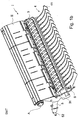
- the Figures 1a and 1b show a side view and a three-dimensional representation of the basic comb II, provided with sieve elements 41, of the comminution device according to the prior art.
- the shredding roller 1 is arranged in a frame, not shown, as is the base comb II with the elements arranged thereon.
- the comb system according to the invention is indicated schematically with an arrow and the reference symbol I. This consists of a base comb II on which the counter-blades 3 and the sieve elements 41 of the sieving device 4 are arranged.
- the base comb II can be pivoted about an axis A.
- the pivoting movement is realized by a pivoting device 5, which is formed from a hydraulic cylinder 50 which is fastened in the device via a base comb axis 51 and a housing axis 52.
- the housing axis is provided on the frame, not shown, of the shredding device.
- the sieve elements 41 are attached to a suspension 7, which is part of the storage, on the base comb II.
- the resilient mounting is achieved by the suspension 6, which, like the suspension 7, are arranged on a preferably exchangeable receptacle 10.
- the suspension 7 and the suspension 6 are provided in parallel spaced apart from one another, which means that both the pretensioning force of the spring 61 and the pitch angle ⁇ of the sieve elements 41 can be changed with the aid of an adjusting device 62.
- a compression spring which is at least partially arranged in a spring sleeve 63, is provided as the spring 61.
- the suspension 7 of the screen elements 41 can be designed as a cardanic suspension.
- the pivoting device 5 also comprises a further hydraulic cylinder 9, which, however, acts in the opposite direction to the hydraulic cylinder 50.
- the distance between the base comb II and the shredding roller 1 is set to the stop by the hydraulic cylinder 9.
- a toothed strip 31 is provided on the base comb II, on which the counter blades 3 are provided individually or as an assembly with a plurality of counter blades 3.
- a wear plate 32 is also provided between the toothed bar 31 and the counter-blade 3, which is designed as a comb tooth, which prevents the entire base comb II from having to be replaced in the event of wear. You then only exchange the wear plate.
- the counter blades 3 are fixed to the base comb by means of a lock 10, which can preferably also be designed hydraulically.
- the solution according to the invention is shown. It was limited to a lateral representation of a sieve element 41 and the suspension 6.
- the suspension 6 is indicated schematically with an arrow.
- the suspension 6 consists of the compression spring 61. This is designed as a spiral spring.
- the compression spring 61 has end disks 65, which have fastening options at their ends, which are not shown in detail.
- the compression spring 61 can be arranged at least partially in a spring sleeve 63.
- the suspension 6 has an end position limit B. This is also only indicated schematically with an arrow.
- the preferred solution according to the invention is characterized in that the suspension 6 is formed from at least one compression spring 61 designed as a spiral spring, in the core of which at least one cylindrical body 64 is arranged.
- the cylindrical body 64 extends only over part of the inner spring travel of the compression spring 61.
- this structural solution is not to be understood as a restriction for the invention. Rather, the solution according to the invention also includes a variant in which the entire spring travel of the compression spring is filled by this cylindrical body 64.
- the cylindrical body 64 consists of an elastic material which has a progressive pressure-displacement characteristic.
- the outer diameter of the cylindrical body 64 corresponds to the inner diameter of the compression spring 61.
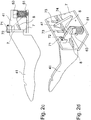
- the suspension 7 is structurally solved somewhat differently according to the invention than in the prior art. It is designed at right angles, with the compression spring 61 being arranged on one leg of the right angle and a locking piece 71 on the other leg, which can be fastened to the suspension 7 by means of a fastening element 72. At least on the side of the suspension 7 facing the locking piece 71, this is either fork-shaped or designed as an angle element.
- the sieve element 41 is encompassed by the “fork” of the locking piece 71 on the side facing the suspension 7 or is fastened at least on one side by the angle of the locking piece 71.
- flat iron pieces 8 are provided, which guide the rearwardly facing leg of the sieve element 41 laterally. These flat iron pieces 8 can be bevelled laterally on the side of the leg of the sieve element 41, so that they allow lateral movement up to certain limits. A limited, cardanic behavior of the sieve elements 41 can thus be achieved.
- the Figures 2c and 2d show the previously described solution of the Figures 2a and 2b , but here once as a sectional side view and as a three-dimensional representation. It can be seen in particular from the three-dimensional representation that the locking piece 71 can be designed both as a fork or as an angle. In the fork-shaped configuration, the sieve element 41 is encompassed on both sides, while in the angular configuration it is only supported on one side. A sieve element 41 is fixed to the suspension 7, while 2 further sieve elements can still be mounted through the openings 73.
- the flat iron pieces 8 described above form an additional, lateral guide for the sieve elements 41.
- a bolt is provided here as the fastening means 72, which is secured by means of a split pin.
- a stiffening plate 74 reinforces the suspension 7.
Landscapes
- Engineering & Computer Science (AREA)
- Food Science & Technology (AREA)
- Crushing And Grinding (AREA)
- Crushing And Pulverization Processes (AREA)
- Disintegrating Or Milling (AREA)
Priority Applications (1)
| Application Number | Priority Date | Filing Date | Title |
|---|---|---|---|
| PL18725737T PL3621743T3 (pl) | 2017-05-08 | 2018-05-07 | Urządzenie rozdrabniające z układem grzebieniowym |
Applications Claiming Priority (3)
| Application Number | Priority Date | Filing Date | Title |
|---|---|---|---|
| DE202017002387 | 2017-05-08 | ||
| DE202018000803.6U DE202018000803U1 (de) | 2017-05-08 | 2018-02-16 | Zerkleinerungsvorrichtung mit einem Kammsystem |
| PCT/EP2018/000240 WO2018206143A1 (de) | 2017-05-08 | 2018-05-07 | Zerkleinerungsvorrichtung mit einem kammsystem |
Publications (2)
| Publication Number | Publication Date |
|---|---|
| EP3621743A1 EP3621743A1 (de) | 2020-03-18 |
| EP3621743B1 true EP3621743B1 (de) | 2021-03-03 |
Family
ID=63372195
Family Applications (1)
| Application Number | Title | Priority Date | Filing Date |
|---|---|---|---|
| EP18725737.3A Active EP3621743B1 (de) | 2017-05-08 | 2018-05-07 | Zerkleinerungsvorrichtung mit einem kammsystem |
Country Status (10)
| Country | Link |
|---|---|
| US (1) | US11110465B2 (enExample) |
| EP (1) | EP3621743B1 (enExample) |
| JP (1) | JP7344799B2 (enExample) |
| KR (1) | KR102514282B1 (enExample) |
| CN (1) | CN110573258B (enExample) |
| CA (1) | CA3060116C (enExample) |
| DE (1) | DE202018000803U1 (enExample) |
| ES (1) | ES2872001T3 (enExample) |
| PL (1) | PL3621743T3 (enExample) |
| WO (1) | WO2018206143A1 (enExample) |
Families Citing this family (6)
| Publication number | Priority date | Publication date | Assignee | Title |
|---|---|---|---|---|
| CN113145247A (zh) * | 2021-04-27 | 2021-07-23 | 重庆披荆斩棘科技有限公司 | 一种原料粉碎装置及其使用方法 |
| PL4108338T3 (pl) | 2021-06-21 | 2026-06-01 | Vermeer Manufacturing Company | Rozdrabniacz do rozdrabniania materiałów luzem |
| CN114146770B (zh) * | 2021-12-02 | 2023-10-03 | 湖南林宇科技发展有限公司 | 一种用于园林绿化的垃圾分类回收装置 |
| CN115194941B (zh) * | 2022-07-23 | 2023-09-22 | 北京中实上庄混凝土有限责任公司 | 一种混凝土防冷凝搅拌装置 |
| DE102024114476B3 (de) * | 2024-02-28 | 2025-04-10 | Doppstadt Beteiligungs Gmbh | Zerkleinerungsvorrichtung |
| EP4647172A1 (de) | 2024-05-10 | 2025-11-12 | Doppstadt Beteiligungs GmbH | Zerkleinerungsvorrichtung |
Family Cites Families (21)
| Publication number | Priority date | Publication date | Assignee | Title |
|---|---|---|---|---|
| US2261090A (en) * | 1939-04-26 | 1941-10-28 | Chain Belt Co | Triturating apparatus |
| JPS6111508Y2 (enExample) * | 1977-02-15 | 1986-04-11 | ||
| JPS6119686U (ja) * | 1984-07-11 | 1986-02-04 | 株式会社富士通ゼネラル | 圧縮機の取付装置 |
| DE3624826A1 (de) * | 1986-07-23 | 1988-02-04 | Lindemann Maschfab Gmbh | Rost fuer zerkleinerungsmaschinen |
| SU1444158A1 (ru) * | 1987-04-06 | 1988-12-15 | Научно-производственное объединение "Нефтехимавтоматика" | Устройство дл измельчени |
| DE4311435B4 (de) * | 1993-04-07 | 2005-10-06 | Werner Doppstadt | Zerkleinerungsmaschine mit Nachzerkleinerungskorb |
| JPH0738786U (ja) * | 1993-12-17 | 1995-07-14 | 倉敷化工株式会社 | 防振装置 |
| DE29910772U1 (de) * | 1999-06-21 | 1999-11-18 | Doppstadt Umwelttechnik Verwaltungsgesellschaft mbH, 42555 Velbert | Zerkleinerungsmaschine |
| DE202006003533U1 (de) * | 2005-06-08 | 2006-10-19 | Doppstadt Calbe Gmbh | Siebvorrichtung |
| DE202006006802U1 (de) * | 2006-04-25 | 2007-08-30 | Doppstadt Calbe Gmbh | Zerkleinerungsvorrichtung |
| JP5363467B2 (ja) * | 2008-05-08 | 2013-12-11 | 日立建機株式会社 | 破砕機 |
| CN201543467U (zh) * | 2009-11-13 | 2010-08-11 | 扬州伟江机械有限公司 | 高效环锤式细碎机 |
| CN202096987U (zh) * | 2011-04-22 | 2012-01-04 | 江油黄龙破碎输送设备制造有限公司 | 一种组合式反击板 |
| DE102012011776A1 (de) * | 2011-07-26 | 2013-01-31 | Hans-Joachim Boltersdorf | Pulper mit einer Welle und Verfahren zur Behandlung von Verbundmaterialien |
| CN202410747U (zh) * | 2011-10-31 | 2012-09-05 | 杨桦 | 自动筛分组合破碎机 |
| CN202447132U (zh) * | 2011-11-30 | 2012-09-26 | 郑州一帆机械设备有限公司 | 研磨架可调的反击式破碎机 |
| US10099224B2 (en) * | 2011-12-22 | 2018-10-16 | Astec Industries, Inc. | Material reducing device |
| CN202590883U (zh) * | 2012-05-29 | 2012-12-12 | 湖南龙昶机械工程有限公司 | 一种制砂机用的可调式反击衬板组件 |
| NL2009580C2 (nl) * | 2012-10-05 | 2014-04-08 | Galiën Hannie | Verkleiner voor het verkleinen van grof materiaal en werkwijze daarvoor. |
| DE202015003527U1 (de) * | 2014-12-19 | 2016-03-22 | Doppstadt Familienholding Gmbh | Zerkleinerungsvorrichtung mit einem Kammsystem |
| CN105953011B (zh) * | 2016-06-24 | 2018-05-29 | 中航光电科技股份有限公司 | 公接头及使用该公接头的快速接头组件 |
-
2018
- 2018-02-16 DE DE202018000803.6U patent/DE202018000803U1/de active Active
- 2018-05-07 KR KR1020197027090A patent/KR102514282B1/ko active Active
- 2018-05-07 PL PL18725737T patent/PL3621743T3/pl unknown
- 2018-05-07 CN CN201880028105.4A patent/CN110573258B/zh active Active
- 2018-05-07 WO PCT/EP2018/000240 patent/WO2018206143A1/de not_active Ceased
- 2018-05-07 CA CA3060116A patent/CA3060116C/en active Active
- 2018-05-07 EP EP18725737.3A patent/EP3621743B1/de active Active
- 2018-05-07 JP JP2019559018A patent/JP7344799B2/ja active Active
- 2018-05-07 ES ES18725737T patent/ES2872001T3/es active Active
- 2018-05-07 US US16/492,759 patent/US11110465B2/en active Active
Non-Patent Citations (1)
| Title |
|---|
| None * |
Also Published As
| Publication number | Publication date |
|---|---|
| JP7344799B2 (ja) | 2023-09-14 |
| PL3621743T3 (pl) | 2021-09-13 |
| US20200070177A1 (en) | 2020-03-05 |
| ES2872001T3 (es) | 2021-11-02 |
| CN110573258B (zh) | 2021-08-06 |
| KR20200006034A (ko) | 2020-01-17 |
| WO2018206143A1 (de) | 2018-11-15 |
| CN110573258A (zh) | 2019-12-13 |
| JP2020518445A (ja) | 2020-06-25 |
| CA3060116C (en) | 2022-02-22 |
| US11110465B2 (en) | 2021-09-07 |
| KR102514282B1 (ko) | 2023-03-27 |
| CA3060116A1 (en) | 2018-11-15 |
| EP3621743A1 (de) | 2020-03-18 |
| DE202018000803U1 (de) | 2018-08-09 |
Similar Documents
| Publication | Publication Date | Title |
|---|---|---|
| WO2018206143A1 (de) | Zerkleinerungsvorrichtung mit einem kammsystem | |
| EP2012927B1 (de) | Zerkleinerungsvorrichtung | |
| EP2012928A1 (de) | Schlegel für eine zerkleinerungsvorrichtung | |
| DE202009013767U1 (de) | Rastgelenk und Aussenspiegel mit einem solchen Rastgelenk | |
| WO2016096103A1 (de) | Zerkleinerungsvorrichtung mit einem kammsystem | |
| DE202005009859U1 (de) | Messerträger für Zerkleinerungsvorrichtungen | |
| WO2012010141A1 (de) | Segmentkorper für einen fordergutabstreifer | |
| EP1726403A2 (de) | Klemmhebel mit höhenverstellbarem Gegenlager | |
| DE102011011658A1 (de) | Einzugsvorrichtung für einen Feldhäcksler | |
| DE102011016618A1 (de) | Landwirtschaftliches Schneidwerk | |
| DE7118201U (de) | Bodenbearbeitungsgeraet mit werkzeugausloesevorrichtung | |
| DE102012005027A1 (de) | Bodenbearbeitungsgerät und Federzinkenlagerelement | |
| DE4202771C2 (de) | Überlastsicherung von Bodenbearbeitungsmaschinen | |
| DE2050865C3 (de) | Schlag-Schneidwerk insbesondere zum Zerkleinern von Stroh, Grünfutter u.dgl | |
| EP1125488B1 (de) | Bodenbearbeitungsgerät mit Überlastsicherung | |
| DE20320931U1 (de) | Drehbares Gelenk und Träger mit einem drehbaren Gelenk | |
| DE102005023014B4 (de) | Vorrichtung zum Schneiden von insbesondere hoch wachsendem Schnittgut | |
| DE19810682C1 (de) | Überlastgesicherter Bodengrubber | |
| EP3772890B1 (de) | Obermesserschwinghebelführung für oszillierende doppelmesserschneidsysteme | |
| DE10331494B4 (de) | Stuhl | |
| EP1799897B1 (de) | Stützlager für eine webmaschine und webmaschine mit einem stützlager | |
| DE102010017656B4 (de) | Vorrichtung zum Abschneiden und Zerschneiden von Schnittgut | |
| AT507355A2 (de) | Prallbrecher | |
| AT396048B (de) | Schneidvorrichtung | |
| DE102010054376B4 (de) | Haltevorrichtung für das Gegenmesser in einer Holzhackmaschine |
Legal Events
| Date | Code | Title | Description |
|---|---|---|---|
| STAA | Information on the status of an ep patent application or granted ep patent |
Free format text: STATUS: UNKNOWN |
|
| STAA | Information on the status of an ep patent application or granted ep patent |
Free format text: STATUS: THE INTERNATIONAL PUBLICATION HAS BEEN MADE |
|
| PUAI | Public reference made under article 153(3) epc to a published international application that has entered the european phase |
Free format text: ORIGINAL CODE: 0009012 |
|
| STAA | Information on the status of an ep patent application or granted ep patent |
Free format text: STATUS: REQUEST FOR EXAMINATION WAS MADE |
|
| 17P | Request for examination filed |
Effective date: 20190827 |
|
| AK | Designated contracting states |
Kind code of ref document: A1 Designated state(s): AL AT BE BG CH CY CZ DE DK EE ES FI FR GB GR HR HU IE IS IT LI LT LU LV MC MK MT NL NO PL PT RO RS SE SI SK SM TR |
|
| AX | Request for extension of the european patent |
Extension state: BA ME |
|
| DAV | Request for validation of the european patent (deleted) | ||
| DAX | Request for extension of the european patent (deleted) | ||
| GRAP | Despatch of communication of intention to grant a patent |
Free format text: ORIGINAL CODE: EPIDOSNIGR1 |
|
| RIC1 | Information provided on ipc code assigned before grant |
Ipc: B02C 18/16 20060101ALI20201012BHEP Ipc: B02C 18/14 20060101AFI20201012BHEP Ipc: B02C 23/16 20060101ALI20201012BHEP Ipc: B02C 18/18 20060101ALI20201012BHEP |
|
| STAA | Information on the status of an ep patent application or granted ep patent |
Free format text: STATUS: GRANT OF PATENT IS INTENDED |
|
| INTG | Intention to grant announced |
Effective date: 20201119 |
|
| GRAS | Grant fee paid |
Free format text: ORIGINAL CODE: EPIDOSNIGR3 |
|
| GRAA | (expected) grant |
Free format text: ORIGINAL CODE: 0009210 |
|
| STAA | Information on the status of an ep patent application or granted ep patent |
Free format text: STATUS: THE PATENT HAS BEEN GRANTED |
|
| AK | Designated contracting states |
Kind code of ref document: B1 Designated state(s): AL AT BE BG CH CY CZ DE DK EE ES FI FR GB GR HR HU IE IS IT LI LT LU LV MC MK MT NL NO PL PT RO RS SE SI SK SM TR |
|
| REG | Reference to a national code |
Ref country code: GB Ref legal event code: FG4D Free format text: NOT ENGLISH |
|
| REG | Reference to a national code |
Ref country code: AT Ref legal event code: REF Ref document number: 1366619 Country of ref document: AT Kind code of ref document: T Effective date: 20210315 Ref country code: CH Ref legal event code: EP |
|
| REG | Reference to a national code |
Ref country code: DE Ref legal event code: R096 Ref document number: 502018004161 Country of ref document: DE |
|
| REG | Reference to a national code |
Ref country code: IE Ref legal event code: FG4D Free format text: LANGUAGE OF EP DOCUMENT: GERMAN |
|
| REG | Reference to a national code |
Ref country code: LT Ref legal event code: MG9D |
|
| REG | Reference to a national code |
Ref country code: DE Ref legal event code: R081 Ref document number: 502018004161 Country of ref document: DE Owner name: DOPPSTADT BETEILIGUNGS GMBH, DE Free format text: FORMER OWNER: LIG GMBH, 42555 VELBERT, DE Ref country code: DE Ref legal event code: R081 Ref document number: 502018004161 Country of ref document: DE Owner name: LIG GMBH, DE Free format text: FORMER OWNER: LIG GMBH, 42555 VELBERT, DE |
|
| PG25 | Lapsed in a contracting state [announced via postgrant information from national office to epo] |
Ref country code: GR Free format text: LAPSE BECAUSE OF FAILURE TO SUBMIT A TRANSLATION OF THE DESCRIPTION OR TO PAY THE FEE WITHIN THE PRESCRIBED TIME-LIMIT Effective date: 20210604 Ref country code: FI Free format text: LAPSE BECAUSE OF FAILURE TO SUBMIT A TRANSLATION OF THE DESCRIPTION OR TO PAY THE FEE WITHIN THE PRESCRIBED TIME-LIMIT Effective date: 20210303 Ref country code: HR Free format text: LAPSE BECAUSE OF FAILURE TO SUBMIT A TRANSLATION OF THE DESCRIPTION OR TO PAY THE FEE WITHIN THE PRESCRIBED TIME-LIMIT Effective date: 20210303 Ref country code: BG Free format text: LAPSE BECAUSE OF FAILURE TO SUBMIT A TRANSLATION OF THE DESCRIPTION OR TO PAY THE FEE WITHIN THE PRESCRIBED TIME-LIMIT Effective date: 20210603 Ref country code: NO Free format text: LAPSE BECAUSE OF FAILURE TO SUBMIT A TRANSLATION OF THE DESCRIPTION OR TO PAY THE FEE WITHIN THE PRESCRIBED TIME-LIMIT Effective date: 20210603 Ref country code: LT Free format text: LAPSE BECAUSE OF FAILURE TO SUBMIT A TRANSLATION OF THE DESCRIPTION OR TO PAY THE FEE WITHIN THE PRESCRIBED TIME-LIMIT Effective date: 20210303 |
|
| REG | Reference to a national code |
Ref country code: NL Ref legal event code: MP Effective date: 20210303 |
|
| RAP4 | Party data changed (patent owner data changed or rights of a patent transferred) |
Owner name: LIG GMBH |
|
| PG25 | Lapsed in a contracting state [announced via postgrant information from national office to epo] |
Ref country code: SE Free format text: LAPSE BECAUSE OF FAILURE TO SUBMIT A TRANSLATION OF THE DESCRIPTION OR TO PAY THE FEE WITHIN THE PRESCRIBED TIME-LIMIT Effective date: 20210303 Ref country code: RS Free format text: LAPSE BECAUSE OF FAILURE TO SUBMIT A TRANSLATION OF THE DESCRIPTION OR TO PAY THE FEE WITHIN THE PRESCRIBED TIME-LIMIT Effective date: 20210303 Ref country code: LV Free format text: LAPSE BECAUSE OF FAILURE TO SUBMIT A TRANSLATION OF THE DESCRIPTION OR TO PAY THE FEE WITHIN THE PRESCRIBED TIME-LIMIT Effective date: 20210303 |
|
| PG25 | Lapsed in a contracting state [announced via postgrant information from national office to epo] |
Ref country code: NL Free format text: LAPSE BECAUSE OF FAILURE TO SUBMIT A TRANSLATION OF THE DESCRIPTION OR TO PAY THE FEE WITHIN THE PRESCRIBED TIME-LIMIT Effective date: 20210303 |
|
| PG25 | Lapsed in a contracting state [announced via postgrant information from national office to epo] |
Ref country code: SM Free format text: LAPSE BECAUSE OF FAILURE TO SUBMIT A TRANSLATION OF THE DESCRIPTION OR TO PAY THE FEE WITHIN THE PRESCRIBED TIME-LIMIT Effective date: 20210303 Ref country code: CZ Free format text: LAPSE BECAUSE OF FAILURE TO SUBMIT A TRANSLATION OF THE DESCRIPTION OR TO PAY THE FEE WITHIN THE PRESCRIBED TIME-LIMIT Effective date: 20210303 Ref country code: EE Free format text: LAPSE BECAUSE OF FAILURE TO SUBMIT A TRANSLATION OF THE DESCRIPTION OR TO PAY THE FEE WITHIN THE PRESCRIBED TIME-LIMIT Effective date: 20210303 |
|
| REG | Reference to a national code |
Ref country code: ES Ref legal event code: FG2A Ref document number: 2872001 Country of ref document: ES Kind code of ref document: T3 Effective date: 20211102 |
|
| PG25 | Lapsed in a contracting state [announced via postgrant information from national office to epo] |
Ref country code: IS Free format text: LAPSE BECAUSE OF FAILURE TO SUBMIT A TRANSLATION OF THE DESCRIPTION OR TO PAY THE FEE WITHIN THE PRESCRIBED TIME-LIMIT Effective date: 20210703 Ref country code: SK Free format text: LAPSE BECAUSE OF FAILURE TO SUBMIT A TRANSLATION OF THE DESCRIPTION OR TO PAY THE FEE WITHIN THE PRESCRIBED TIME-LIMIT Effective date: 20210303 Ref country code: RO Free format text: LAPSE BECAUSE OF FAILURE TO SUBMIT A TRANSLATION OF THE DESCRIPTION OR TO PAY THE FEE WITHIN THE PRESCRIBED TIME-LIMIT Effective date: 20210303 Ref country code: PT Free format text: LAPSE BECAUSE OF FAILURE TO SUBMIT A TRANSLATION OF THE DESCRIPTION OR TO PAY THE FEE WITHIN THE PRESCRIBED TIME-LIMIT Effective date: 20210705 |
|
| REG | Reference to a national code |
Ref country code: DE Ref legal event code: R097 Ref document number: 502018004161 Country of ref document: DE |
|
| REG | Reference to a national code |
Ref country code: CH Ref legal event code: PL |
|
| PLBE | No opposition filed within time limit |
Free format text: ORIGINAL CODE: 0009261 |
|
| STAA | Information on the status of an ep patent application or granted ep patent |
Free format text: STATUS: NO OPPOSITION FILED WITHIN TIME LIMIT |
|
| PG25 | Lapsed in a contracting state [announced via postgrant information from national office to epo] |
Ref country code: DK Free format text: LAPSE BECAUSE OF FAILURE TO SUBMIT A TRANSLATION OF THE DESCRIPTION OR TO PAY THE FEE WITHIN THE PRESCRIBED TIME-LIMIT Effective date: 20210303 Ref country code: CH Free format text: LAPSE BECAUSE OF NON-PAYMENT OF DUE FEES Effective date: 20210531 Ref country code: AL Free format text: LAPSE BECAUSE OF FAILURE TO SUBMIT A TRANSLATION OF THE DESCRIPTION OR TO PAY THE FEE WITHIN THE PRESCRIBED TIME-LIMIT Effective date: 20210303 Ref country code: LU Free format text: LAPSE BECAUSE OF NON-PAYMENT OF DUE FEES Effective date: 20210507 Ref country code: LI Free format text: LAPSE BECAUSE OF NON-PAYMENT OF DUE FEES Effective date: 20210531 Ref country code: MC Free format text: LAPSE BECAUSE OF FAILURE TO SUBMIT A TRANSLATION OF THE DESCRIPTION OR TO PAY THE FEE WITHIN THE PRESCRIBED TIME-LIMIT Effective date: 20210303 |
|
| 26N | No opposition filed |
Effective date: 20211206 |
|
| REG | Reference to a national code |
Ref country code: BE Ref legal event code: MM Effective date: 20210531 |
|
| PG25 | Lapsed in a contracting state [announced via postgrant information from national office to epo] |
Ref country code: SI Free format text: LAPSE BECAUSE OF FAILURE TO SUBMIT A TRANSLATION OF THE DESCRIPTION OR TO PAY THE FEE WITHIN THE PRESCRIBED TIME-LIMIT Effective date: 20210303 |
|
| PG25 | Lapsed in a contracting state [announced via postgrant information from national office to epo] |
Ref country code: IE Free format text: LAPSE BECAUSE OF NON-PAYMENT OF DUE FEES Effective date: 20210507 |
|
| PG25 | Lapsed in a contracting state [announced via postgrant information from national office to epo] |
Ref country code: IS Free format text: LAPSE BECAUSE OF FAILURE TO SUBMIT A TRANSLATION OF THE DESCRIPTION OR TO PAY THE FEE WITHIN THE PRESCRIBED TIME-LIMIT Effective date: 20210703 |
|
| PG25 | Lapsed in a contracting state [announced via postgrant information from national office to epo] |
Ref country code: BE Free format text: LAPSE BECAUSE OF NON-PAYMENT OF DUE FEES Effective date: 20210531 |
|
| REG | Reference to a national code |
Ref country code: DE Ref legal event code: R081 Ref document number: 502018004161 Country of ref document: DE Owner name: DOPPSTADT BETEILIGUNGS GMBH, DE Free format text: FORMER OWNER: LIG GMBH, 42551 VELBERT, DE |
|
| PG25 | Lapsed in a contracting state [announced via postgrant information from national office to epo] |
Ref country code: CY Free format text: LAPSE BECAUSE OF FAILURE TO SUBMIT A TRANSLATION OF THE DESCRIPTION OR TO PAY THE FEE WITHIN THE PRESCRIBED TIME-LIMIT Effective date: 20210303 |
|
| P01 | Opt-out of the competence of the unified patent court (upc) registered |
Effective date: 20230613 |
|
| PG25 | Lapsed in a contracting state [announced via postgrant information from national office to epo] |
Ref country code: HU Free format text: LAPSE BECAUSE OF FAILURE TO SUBMIT A TRANSLATION OF THE DESCRIPTION OR TO PAY THE FEE WITHIN THE PRESCRIBED TIME-LIMIT; INVALID AB INITIO Effective date: 20180507 |
|
| PG25 | Lapsed in a contracting state [announced via postgrant information from national office to epo] |
Ref country code: MK Free format text: LAPSE BECAUSE OF FAILURE TO SUBMIT A TRANSLATION OF THE DESCRIPTION OR TO PAY THE FEE WITHIN THE PRESCRIBED TIME-LIMIT Effective date: 20210303 |
|
| REG | Reference to a national code |
Ref country code: AT Ref legal event code: MM01 Ref document number: 1366619 Country of ref document: AT Kind code of ref document: T Effective date: 20230507 |
|
| PG25 | Lapsed in a contracting state [announced via postgrant information from national office to epo] |
Ref country code: AT Free format text: LAPSE BECAUSE OF NON-PAYMENT OF DUE FEES Effective date: 20230507 |
|
| PG25 | Lapsed in a contracting state [announced via postgrant information from national office to epo] |
Ref country code: AT Free format text: LAPSE BECAUSE OF NON-PAYMENT OF DUE FEES Effective date: 20230507 |
|
| PG25 | Lapsed in a contracting state [announced via postgrant information from national office to epo] |
Ref country code: MT Free format text: LAPSE BECAUSE OF FAILURE TO SUBMIT A TRANSLATION OF THE DESCRIPTION OR TO PAY THE FEE WITHIN THE PRESCRIBED TIME-LIMIT Effective date: 20210303 |
|
| PGFP | Annual fee paid to national office [announced via postgrant information from national office to epo] |
Ref country code: ES Payment date: 20250630 Year of fee payment: 8 |
|
| PGFP | Annual fee paid to national office [announced via postgrant information from national office to epo] |
Ref country code: GB Payment date: 20260306 Year of fee payment: 9 |
|
| PGFP | Annual fee paid to national office [announced via postgrant information from national office to epo] |
Ref country code: AT Payment date: 20260410 Year of fee payment: 5 |
|
| PGFP | Annual fee paid to national office [announced via postgrant information from national office to epo] |
Ref country code: PL Payment date: 20260423 Year of fee payment: 9 |
|
| PGFP | Annual fee paid to national office [announced via postgrant information from national office to epo] |
Ref country code: IT Payment date: 20260525 Year of fee payment: 9 |
|
| PGFP | Annual fee paid to national office [announced via postgrant information from national office to epo] |
Ref country code: DE Payment date: 20260518 Year of fee payment: 9 |
|
| PGFP | Annual fee paid to national office [announced via postgrant information from national office to epo] |
Ref country code: TR Payment date: 20260429 Year of fee payment: 9 |
|
| PGFP | Annual fee paid to national office [announced via postgrant information from national office to epo] |
Ref country code: FR Payment date: 20260526 Year of fee payment: 9 |