EP3620331B1 - Fahrzeugumgebungsanzeigevorrichtung - Google Patents
Fahrzeugumgebungsanzeigevorrichtung Download PDFInfo
- Publication number
- EP3620331B1 EP3620331B1 EP19190820.1A EP19190820A EP3620331B1 EP 3620331 B1 EP3620331 B1 EP 3620331B1 EP 19190820 A EP19190820 A EP 19190820A EP 3620331 B1 EP3620331 B1 EP 3620331B1
- Authority
- EP
- European Patent Office
- Prior art keywords
- vehicle
- shut
- display device
- power
- predetermined
- Prior art date
- Legal status (The legal status is an assumption and is not a legal conclusion. Google has not performed a legal analysis and makes no representation as to the accuracy of the status listed.)
- Active
Links
Images




Classifications
-
- B—PERFORMING OPERATIONS; TRANSPORTING
- B60—VEHICLES IN GENERAL
- B60R—VEHICLES, VEHICLE FITTINGS, OR VEHICLE PARTS, NOT OTHERWISE PROVIDED FOR
- B60R16/00—Electric or fluid circuits specially adapted for vehicles and not otherwise provided for; Arrangement of elements of electric or fluid circuits specially adapted for vehicles and not otherwise provided for
- B60R16/02—Electric or fluid circuits specially adapted for vehicles and not otherwise provided for; Arrangement of elements of electric or fluid circuits specially adapted for vehicles and not otherwise provided for electric constitutive elements
- B60R16/023—Electric or fluid circuits specially adapted for vehicles and not otherwise provided for; Arrangement of elements of electric or fluid circuits specially adapted for vehicles and not otherwise provided for electric constitutive elements for transmission of signals between vehicle parts or subsystems
- B60R16/0231—Circuits relating to the driving or the functioning of the vehicle
-
- B—PERFORMING OPERATIONS; TRANSPORTING
- B60—VEHICLES IN GENERAL
- B60R—VEHICLES, VEHICLE FITTINGS, OR VEHICLE PARTS, NOT OTHERWISE PROVIDED FOR
- B60R16/00—Electric or fluid circuits specially adapted for vehicles and not otherwise provided for; Arrangement of elements of electric or fluid circuits specially adapted for vehicles and not otherwise provided for
- B60R16/02—Electric or fluid circuits specially adapted for vehicles and not otherwise provided for; Arrangement of elements of electric or fluid circuits specially adapted for vehicles and not otherwise provided for electric constitutive elements
- B60R16/03—Electric or fluid circuits specially adapted for vehicles and not otherwise provided for; Arrangement of elements of electric or fluid circuits specially adapted for vehicles and not otherwise provided for electric constitutive elements for supply of electrical power to vehicle subsystems or for
- B60R16/033—Electric or fluid circuits specially adapted for vehicles and not otherwise provided for; Arrangement of elements of electric or fluid circuits specially adapted for vehicles and not otherwise provided for electric constitutive elements for supply of electrical power to vehicle subsystems or for characterised by the use of electrical cells or batteries
-
- B—PERFORMING OPERATIONS; TRANSPORTING
- B60—VEHICLES IN GENERAL
- B60R—VEHICLES, VEHICLE FITTINGS, OR VEHICLE PARTS, NOT OTHERWISE PROVIDED FOR
- B60R99/00—Subject matter not provided for in other groups of this subclass
-
- B—PERFORMING OPERATIONS; TRANSPORTING
- B60—VEHICLES IN GENERAL
- B60R—VEHICLES, VEHICLE FITTINGS, OR VEHICLE PARTS, NOT OTHERWISE PROVIDED FOR
- B60R1/00—Optical viewing arrangements; Real-time viewing arrangements for drivers or passengers using optical image capturing systems, e.g. cameras or video systems specially adapted for use in or on vehicles
- B60R1/20—Real-time viewing arrangements for drivers or passengers using optical image capturing systems, e.g. cameras or video systems specially adapted for use in or on vehicles
- B60R1/22—Real-time viewing arrangements for drivers or passengers using optical image capturing systems, e.g. cameras or video systems specially adapted for use in or on vehicles for viewing an area outside the vehicle, e.g. the exterior of the vehicle
- B60R1/23—Real-time viewing arrangements for drivers or passengers using optical image capturing systems, e.g. cameras or video systems specially adapted for use in or on vehicles for viewing an area outside the vehicle, e.g. the exterior of the vehicle with a predetermined field of view
- B60R1/26—Real-time viewing arrangements for drivers or passengers using optical image capturing systems, e.g. cameras or video systems specially adapted for use in or on vehicles for viewing an area outside the vehicle, e.g. the exterior of the vehicle with a predetermined field of view to the rear of the vehicle
-
- H—ELECTRICITY
- H04—ELECTRIC COMMUNICATION TECHNIQUE
- H04N—PICTORIAL COMMUNICATION, e.g. TELEVISION
- H04N23/00—Cameras or camera modules comprising electronic image sensors; Control thereof
- H04N23/60—Control of cameras or camera modules
- H04N23/65—Control of camera operation in relation to power supply
- H04N23/651—Control of camera operation in relation to power supply for reducing power consumption by affecting camera operations, e.g. sleep mode, hibernation mode or power off of selective parts of the camera
-
- B—PERFORMING OPERATIONS; TRANSPORTING
- B60—VEHICLES IN GENERAL
- B60R—VEHICLES, VEHICLE FITTINGS, OR VEHICLE PARTS, NOT OTHERWISE PROVIDED FOR
- B60R11/00—Arrangements for holding or mounting articles, not otherwise provided for
- B60R11/02—Arrangements for holding or mounting articles, not otherwise provided for for radio sets, television sets, telephones, or the like; Arrangement of controls thereof
- B60R11/0229—Arrangements for holding or mounting articles, not otherwise provided for for radio sets, television sets, telephones, or the like; Arrangement of controls thereof for displays, e.g. cathodic tubes
- B60R11/0235—Arrangements for holding or mounting articles, not otherwise provided for for radio sets, television sets, telephones, or the like; Arrangement of controls thereof for displays, e.g. cathodic tubes of flat type, e.g. LCD
-
- B—PERFORMING OPERATIONS; TRANSPORTING
- B60—VEHICLES IN GENERAL
- B60R—VEHICLES, VEHICLE FITTINGS, OR VEHICLE PARTS, NOT OTHERWISE PROVIDED FOR
- B60R11/00—Arrangements for holding or mounting articles, not otherwise provided for
- B60R11/04—Mounting of cameras operative during drive; Arrangement of controls thereof relative to the vehicle
-
- B—PERFORMING OPERATIONS; TRANSPORTING
- B60—VEHICLES IN GENERAL
- B60R—VEHICLES, VEHICLE FITTINGS, OR VEHICLE PARTS, NOT OTHERWISE PROVIDED FOR
- B60R11/00—Arrangements for holding or mounting articles, not otherwise provided for
- B60R2011/0001—Arrangements for holding or mounting articles, not otherwise provided for characterised by position
- B60R2011/0003—Arrangements for holding or mounting articles, not otherwise provided for characterised by position inside the vehicle
-
- B—PERFORMING OPERATIONS; TRANSPORTING
- B60—VEHICLES IN GENERAL
- B60R—VEHICLES, VEHICLE FITTINGS, OR VEHICLE PARTS, NOT OTHERWISE PROVIDED FOR
- B60R11/00—Arrangements for holding or mounting articles, not otherwise provided for
- B60R2011/0001—Arrangements for holding or mounting articles, not otherwise provided for characterised by position
- B60R2011/004—Arrangements for holding or mounting articles, not otherwise provided for characterised by position outside the vehicle
-
- B—PERFORMING OPERATIONS; TRANSPORTING
- B60—VEHICLES IN GENERAL
- B60R—VEHICLES, VEHICLE FITTINGS, OR VEHICLE PARTS, NOT OTHERWISE PROVIDED FOR
- B60R2300/00—Details of viewing arrangements using cameras and displays, specially adapted for use in a vehicle
- B60R2300/10—Details of viewing arrangements using cameras and displays, specially adapted for use in a vehicle characterised by the type of camera system used
- B60R2300/105—Details of viewing arrangements using cameras and displays, specially adapted for use in a vehicle characterised by the type of camera system used using multiple cameras
-
- B—PERFORMING OPERATIONS; TRANSPORTING
- B60—VEHICLES IN GENERAL
- B60R—VEHICLES, VEHICLE FITTINGS, OR VEHICLE PARTS, NOT OTHERWISE PROVIDED FOR
- B60R2300/00—Details of viewing arrangements using cameras and displays, specially adapted for use in a vehicle
- B60R2300/80—Details of viewing arrangements using cameras and displays, specially adapted for use in a vehicle characterised by the intended use of the viewing arrangement
- B60R2300/804—Details of viewing arrangements using cameras and displays, specially adapted for use in a vehicle characterised by the intended use of the viewing arrangement for lane monitoring
-
- B—PERFORMING OPERATIONS; TRANSPORTING
- B60—VEHICLES IN GENERAL
- B60R—VEHICLES, VEHICLE FITTINGS, OR VEHICLE PARTS, NOT OTHERWISE PROVIDED FOR
- B60R2300/00—Details of viewing arrangements using cameras and displays, specially adapted for use in a vehicle
- B60R2300/80—Details of viewing arrangements using cameras and displays, specially adapted for use in a vehicle characterised by the intended use of the viewing arrangement
- B60R2300/8046—Details of viewing arrangements using cameras and displays, specially adapted for use in a vehicle characterised by the intended use of the viewing arrangement for replacing a rear-view mirror system
Definitions
- the present disclosure relates to a vehicle surroundings display device.
- US 2018/0086268 describes a case in which when an ignition switch is turned off, imaging by a camera and display of a monitor are continued for a predetermined time, and thereafter, display of the monitor is stopped. Next, when opening of a door is detected by a courtesy switch, in a case in which display of the monitor is stopped, control is carried out to restart the display and enable confirmation of the vehicle periphery. Further, the display of the monitor is stopped in a case in which closing of a door is detected by a courtesy switch and locking is sensed by a door lock.
- JP-A Japanese Patent Application Laid-Open
- This electronic mirror system includes an imaging section, a display section, and a control section.
- the imaging section images sideways from the vehicle and toward the rear side of the vehicle so as to include at least part of the rear wheels of the vehicle.
- the control section enlarges a first area of an image captured by the imaging section, for example confined to the road a comparatively greater distance from the vehicle, and displays the first area on the display section.
- the control section displays on the display section an area of the image captured by the imaging section that is wider than the first area and includes the first area. This enables a driver to view a wider range sideways from the vehicle and to the rear side of the vehicle when the vehicle is turning than when the vehicle is not turning, thereby enabling safer turning in which the wheels do not come off the road or ride up onto a curb.
- the electronic mirror system is operated by a power supply from a vehicle battery. Were operation of the electronic mirror system to be shut down at the same time as a power unit of the vehicle is shut down, the ability to view the vehicle surroundings required when exiting the vehicle and so on would be reduced. There is thus a need to actuate the electronic mirror system for a predetermined duration after the power unit has been shut down. However, since the electronic mirror system is operated by a power supply from the vehicle battery as described above, there is a need to give consideration to a drop in the battery voltage when the electronic mirror system is operated after the power unit has been shut down.
- the present disclosure obtains a vehicle surroundings display device capable of both protecting a battery and securing the ability to view the vehicle surroundings after a power unit of the vehicle has been shut down.
- a first aspect of the present invention provides a vehicle surroundings display device as defined in appended claim 1.
- the vehicle surroundings display device includes the imaging device, the display device, and the controller.
- the imaging device images a region toward a rear side of the vehicle and sideways from the vehicle.
- the display device is capable of displaying an image captured by the imaging device.
- the controller controls display of the display device by selectively adopting the normal active mode, the power-off active mode, the standby mode, or the shut-down mode.
- the normal active mode the imaging device and the display device are in actuated states and the display device is in the image-displaying state when a power unit of the vehicle is in the actuated state.
- the power-off active mode the imaging device and the display device are in actuated states and the display device is in the image-displaying state when the power unit is in the shut-down state.
- the imaging device and the display device are in actuated states and the display device is in a non-image-displaying state when the power unit is in the shut-down state.
- the imaging device and the display device are in shut-down states and the display device is in a non-image-displaying state when the power unit is in the shut-down state.
- transition is made to the standby mode when the first predetermined standby duration has elapsed since transitioning to the power-off active mode, and transition is made from the standby mode to the shut-down mode when a second predetermined standby duration has elapsed.
- the display device in the normal shut-down processing, is in the power-off active mode during the first predetermined standby duration, enabling the vehicle surroundings to be viewed using the display device that is in the image-displaying state.
- the display device can be transitioned quickly to the image-displaying state. This enables a quick transition to a state enabling the vehicle surroundings to be viewed, even when in the standby mode. This enables the ability to view the vehicle surroundings to be improved for a brief period after the power unit has been shut down.
- the imaging device and the display device can adopt the shut-down state at an earlier stage, thereby enabling the amount of power consumed to be suppressed. Namely, this enables the load on the battery supplying power to the vehicle surroundings display device to be reduced.
- a second aspect of the present disclosure is the vehicle surroundings display device of the first aspect, wherein the predetermined shut-down condition in the power-saving processing is a case in which a vehicle door has been locked from outside the vehicle.
- the predetermined shut-down condition in the power-saving processing performed by the controller is a case in which the vehicle door has been locked from outside the vehicle. This enables the amount of power consumed to be effectively suppressed. Namely, a state in which the vehicle door has been locked from outside the vehicle generally equates to a state in which the vehicle is unoccupied, and so there is little need to view the vehicle surroundings from inside the vehicle.
- the vehicle surroundings display device to be activated in a state in which the vehicle door has been locked from outside the vehicle, and so transitioning to the shut-down mode when the vehicle door has been locked from outside the vehicle, without waiting for the first predetermined standby duration or the second predetermined standby duration, enables the amount of power consumed to be effectively suppressed.
- a third aspect of the present disclosure is the vehicle surroundings display device of the first aspect or the second aspect, wherein the predetermined shut-down condition in the power-saving processing is a case in which a vehicle battery voltage has dropped to a predetermined voltage or lower.
- the predetermined shut-down condition in the power-saving processing performed by the controller is a case in which the vehicle battery voltage has dropped to the predetermined voltage or lower.
- This enables a drop in the ability of the power unit to restart to be suppressed. Namely, when there is a marked drop in the battery voltage of the vehicle, the power unit of the vehicle becomes difficult to restart.
- the shut-down mode without waiting for the first predetermined standby duration or the second predetermined standby duration when the battery voltage has dropped to the predetermined voltage or lower, further battery power consumption is suppressed. Namely, a drop in the battery voltage can be suppressed, enabling a drop in the ability of the power unit to restart to be suppressed.
- a fourth aspect of the present disclosure is the vehicle surroundings display device of any one of the first aspect to the third aspect, wherein the predetermined shut-down condition in the power-saving processing is a case in which a vehicle door of the vehicle has been opened and then closed when a current location of the vehicle is a predetermined location.
- the predetermined shut-down condition in the power-saving processing performed by the controller is a case in which a vehicle door of the vehicle has been opened and then closed when a current location of the vehicle is a predetermined location, thereby enabling the amount of power consumed to be effectively suppressed.
- a vehicle door of the vehicle has been opened and then closed while the vehicle is in a parking lot such as a parking area, there is a high possibility that the occupant has exited the vehicle, and so there is little need to view the vehicle surroundings from inside the vehicle.
- transitioning to the shut-down mode without waiting for the first predetermined standby duration or the second predetermined standby duration when the vehicle door of the vehicle has been opened and then closed while the current location of the vehicle is the predetermined location enables the amount of power consumed to be effectively suppressed.
- a fifth aspect of the present disclosure is the vehicle surroundings display device of any one of the first aspect to the fourth aspect, wherein the predetermined shut-down condition in the power-saving processing is a case in which a vehicle door of the vehicle has been opened and then closed at a time other than when a hazard lamp of the vehicle is illuminated.
- the predetermined shut-down condition in the power-saving processing performed by the controller is a case in which the vehicle door of the vehicle has been opened and then closed at a time other than when the hazard lamp of the vehicle is illuminated, thereby enabling the amount of power consumed to be effectively suppressed. Namely, in a state in which the vehicle door has been opened and then closed while the hazard lamp is illuminated, the occupant has often only temporarily exited the vehicle, and so there is a high possibility that the occupant will return to the vehicle relatively quickly.
- a sixth aspect of the present disclosure is the vehicle surroundings display device of any one of the first aspect to the fifth aspect, wherein the controller performs activation processing to transition to the power-off active mode or the normal active mode within a predetermined duration in cases in which a predetermined activation condition is satisfied while in the shut-down mode or in the standby mode.
- the controller performs activation processing to transition to the power-off active mode or the normal active mode within the predetermined duration in cases in which the predetermined activation condition is satisfied while in the shut-down mode or in the standby mode.
- This enables the display device to adopt the image-displaying state quickly, even in cases in which the display device is in the non-image-displaying state.
- This enables power consumption to be suppressed by placing the display device in the non-image-displaying state, while enabling the display device to adopt the image-displaying state promptly when necessary, thereby enabling the ability to view the vehicle surroundings to be secured.
- a seventh aspect of the present disclosure is the vehicle surroundings display device of the sixth aspect, wherein a first activation condition of the predetermined activation condition in the activation processing is a case in which the power unit of the vehicle has transitioned from the shut-down state to the actuated state; and the controller performs activation processing to transition from the shut-down mode or the standby mode to the normal active mode in cases in which the first activation condition has been satisfied.
- the first activation condition of the predetermined activation conditions in the activation processing performed by the controller is a case in which the power unit of the vehicle has transitioned from the shut-down state to the actuated state.
- the controller performs activation processing to transition from the shut-down mode or the standby mode to the normal active mode in cases in which the first activation condition has been satisfied, thereby enabling the display device to adopt the image-displaying state quickly in cases in which there is a high possibility that the vehicle will be driven, namely, when the power unit has been actuated. This enables the ability to view the vehicle surroundings to be secured prior to the vehicle being driven, while suppressing power consumption.
- An eighth aspect of the present disclosure is the vehicle surroundings display device of the sixth aspect or the seventh aspect, wherein a second activation condition of the predetermined activation condition in the activation processing is a case in which a vehicle door of the vehicle has been opened; and the controller performs activation processing to transition from the shut-down mode or the standby mode to the power-off active mode in cases in which the second activation condition has been satisfied.
- the second activation condition of the predetermined activation conditions in the activation processing performed by the controller is a case in which the vehicle door has been opened.
- the controller performs the activation processing to transition from the shut-down mode or the standby mode to the power-off active mode in cases in which the second activation condition has been satisfied, thereby enabling the display device to adopt the image-displaying state quickly when an occupant has opened the vehicle door in order to board the vehicle. This enables the ability to view the vehicle surroundings to be secured in cases in which the vehicle has been boarded, while suppressing power consumption.
- the vehicle surroundings display device is capable of both protecting the battery and securing the ability to view the vehicle surroundings after the power unit of the vehicle has been shut down.
- the vehicle surroundings display devices according to the second, fourth, and fifth aspects are capable of effectively protecting the battery.
- the vehicle surroundings display device is capable of securing the ability to restart the power unit.
- the vehicle surroundings display devices are capable of both protecting the battery ore effectively and securing the ability to view the vehicle surroundings after the power unit of the vehicle has been shut down.
- a vehicle surroundings display device 10 includes a camera unit 14 serving as an imaging device mounted to a vehicle 12, a monitor unit 16 serving as a display device, and a control device 18 serving as a controller.
- a base portion of a substantially rectangular block shaped camera support body 20 with a circular arc shaped leading end portion is attached to a vehicle front side end of a vehicle vertical direction intermediate portion of a vehicle door 13 (a left front side door) of the vehicle 12, such that the leading end portion of the camera support body 20 projects toward the vehicle outer side.
- a rear-left facing camera 14L configuring part of the camera unit 14 is attached in the vicinity of the leading end portion of the camera support body 20.
- An imaging optical axis (lens) of the rear-left facing camera 14L faces toward the rear-left of the vehicle so as to image a region to the rear-left side and sideways from the left of the vehicle.
- the camera support body 20 is capable of swinging in the vehicle front-rear direction about an axial direction running substantially along the vehicle vertical direction. Using drive force of an actuator, not illustrated in the drawings, the camera support body 20 is capable of swinging between a stowed position where the length direction of the camera support body 20 substantially follows an outer face of the vehicle, and a deployed position from which the rear-left facing camera 14L captures images at the rear-left of the vehicle. Specific configuration and operation of the rear-left facing camera 14L will be described later.
- a base portion of a camera support body 22 that has a profile with left-right symmetry to the camera support body 20 is attached to a vehicle front side end of a vehicle vertical direction intermediate portion of a vehicle door 13 (a right front side door) of the vehicle 12.
- a rear-right facing camera 14R configuring another part of the camera unit 14 is attached in the vicinity of a leading end portion of the camera support body 22.
- An imaging optical axis (lens) of the rear-right facing camera 14R faces toward the rear-right of the vehicle so as to image a region to the rear-right side and sideways from the right of the vehicle.
- the camera support body 22 is also capable of swinging in the vehicle front-rear direction about an axial direction running substantially along the vehicle vertical direction.
- the camera support body 22 is capable of swinging between a stowed position where the length direction of the camera support body 22 substantially follows an outer face of the vehicle, and a deployed position from which the rear-right facing camera 14R captures images at the rear-right of the vehicle. Specific configuration and operation of the rear-right facing camera 14R will be described later.
- a left monitor 16L configuring part of the monitor unit 16 is provided at a vehicle cabin inner side in the vicinity of a lower end of a left front pillar garnish 26. Specific configuration and operation of the left monitor 16L will be described later.
- a right monitor 16R configuring another part of the monitor unit 16 is provided at the vehicle cabin inner side in the vicinity of a lower end of a right front pillar garnish 28. Specific configuration and operation of the right monitor 16R will be described later.
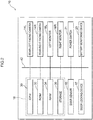
- Fig. 2 is a block diagram illustrating a hardware configuration of the vehicle surroundings display device 10.
- the vehicle surroundings display device 10 is configured including a Central Processing Unit (CPU) 30, Read Only Memory (ROM) 32, Random Access Memory (RAM) 34, and storage 36, each provided within the control device 18, as well as the rear-left facing camera 14L, the rear-right facing camera 14R, the left monitor 16L, the right monitor 16R, a door sensor 15, a door locking device 17, a power switch 21, and a battery monitoring device 23.
- CPU Central Processing Unit
- ROM Read Only Memory
- RAM Random Access Memory
- storage 36 each provided within the control device 18, as well as the rear-left facing camera 14L, the rear-right facing camera 14R, the left monitor 16L, the right monitor 16R, a door sensor 15, a door locking device 17, a power switch 21, and a battery monitoring device 23.
- These configuration elements are connected so as to be capable of communicating with each other through a bus 42.
- the CPU 30 is a central processing unit that executes various programs and controls various sections. Namely, the CPU 30 reads a program from the ROM 32 or the storage 36, and executes the program using the RAM 34 as a workspace. The CPU 30 controls the various configuration elements and performs various computation processing according to the programs stored in the ROM 32 or the storage 36. In the present exemplary embodiment, a display control program to control actuation and shut-down of the camera unit 14 and the monitor unit 16, and to perform image processing on an image to be displayed on the monitor unit 16, is held in the ROM 32 or the storage 36.
- the ROM 32 holds various programs and various data.
- the RAM 34 serves as a workspace in which programs or data are temporarily stored.
- the storage 36 is configured by a Hard Disk Drive (HDD) or a Solid State Drive (SSD), and holds various programs and various data, including an operating system.
- HDD Hard Disk Drive
- SSD Solid State Drive
- the rear-left facing camera 14L is not provided with a mechanism to adjust the orientation of the imaging optical axis, and has a lens with a fixed focal point and a relatively wide view angle.
- the rear-left facing camera 14L images in a fixed imaging range with a relatively wide view angle to the rear-left side of the vehicle.
- the rear-right facing camera 14R is not provided with a mechanism to adjust the orientation of the imaging optical axis, and has a lens with a fixed focal point and a relatively wide view angle.
- the rear-right facing camera 14R images in a fixed imaging range with a relatively wide view angle to the rear-right side of the vehicle.
- the left monitor 16L is a monitor for displaying images corresponding to the rear-left captured by the rear-left facing camera 14L, and is as an example configured by a liquid crystal display. Namely, the left monitor 16L functions as a substitute for a left outside mirror, and enables an occupant to check the situation in a restricted view region at the rear-left side of the vehicle by viewing an image displayed on the left monitor 16L.
- the right monitor 16R is a monitor for displaying images corresponding to the rear-right captured by the rear-right facing camera 14R, and is as an example configured by a liquid crystal display. Namely, the right monitor 16R functions as a substitute for a right outside mirror, and enables the occupant to check the situation in a restricted view region at the rear-right side of the vehicle by viewing an image displayed on the right monitor 16R. Note that the left monitor 16L and the right monitor 16R have the same screen size as each other.
- the door sensor 15 is a sensor that detects an open or closed state of a corresponding vehicle door 13 of the vehicle 12.
- a magnetic sensor such as a Hall sensors or an MR sensor that detects an electromagnetic field of a non-illustrated sensor magnet provided to a side of the vehicle door 13 may be employed as the door sensor 15.
- the door locking device 17 is a device that locks and unlocks the vehicle doors 13. Locking and unlocking of the vehicle doors 13 may be performed by operating a lock knob 27 (see Fig. 1 ) provided at the vehicle interior, or operating a non-illustrated key cylinder provided at the vehicle exterior. Note that the door locking device 17 includes a communication unit and an actuator connected to the communication unit, neither of which are illustrated in the drawings. Locking and unlocking of doors may therefore be performed by operating a non-illustrated remote key outside the vehicle, without operating the key cylinder from outside the vehicle.
- the power switch 21 (again, see Fig. 1 ) is a switch that actuates and shuts down a non-illustrated power unit of the vehicle 12.
- the power unit of the vehicle 12 of the present exemplary embodiment is a hybrid system configured by a motor and an internal combustion engine, and the hybrid system can be actuated and shut down using the power switch 21. Specifically, the power unit is in an actuated state when the power switch 21 is ON, and the power unit is in a shut-down state when the power switch 21 is OFF.
- the battery monitoring device 23 is a device that monitors the voltage and so on of a non-illustrated auxiliary battery, serving as a battery of the vehicle 12.
- the vehicle surroundings display device 10 with the above configuration is activated by power supplied from the auxiliary battery.
- the vehicle surroundings display device 10 implements various functions using the above-described hardware resources. Explanation follows regarding the functional configuration implemented by the vehicle surroundings display device 10.
- Fig. 3 is a block diagram illustrating an example of functional configuration of the vehicle surroundings display device 10.
- functional configuration of the vehicle surroundings display device 10 includes an imaging section 46 serving as an imaging device, a display section 50 serving as a display device, a control section 48 serving as a controller, and an operation section 49.
- Each functional configuration is implemented by the CPU 30 of the control device 18 reading and executing the display control program stored in the ROM 32 or the storage 36 (see Fig. 2 ).
- the imaging section 46 captures video images of regions to the rear side of the vehicle and sideways from the vehicle using the camera unit 14.
- the camera unit 14 is configured by the rear-left facing camera 14L and the rear-right facing camera 14R, and so a region to the rear side of the vehicle and sideways from the vehicle is captured on both the left and right sides of the vehicle 12.
- the regions sideways from the vehicle captured by the rear-left facing camera 14L and the rear-right facing camera 14R are ranges extending from the positions where the rear-left facing camera 14L and the rear-right facing camera 14R are provided to the vehicle 12 toward the rear side of the vehicle and the vehicle width direction outer sides.
- the control section 48 performs image processing on the images captured by the imaging section 46, and the display section 50 displays these processed images on the left monitor 16L and the right monitor 16R (see Fig. 1 ).
- the control section 48 receives images captured by the imaging section 46, and outputs the received images to the display section 50. Namely, an image captured by the rear-left facing camera 14L is output to the left monitor 16L configuring part of the display section 50. Similarly, an image captured by the rear-right facing camera 14R is output to the right monitor 16R configuring another part of the display section 50.
- the control section 48 receives activation statuses of the power switch 21 and the door locking device 17, and voltage information regarding the auxiliary battery from the battery monitoring device 23, and selects activation states for the imaging section 46 and the display section 50 according to plural modes, described later, based on the activation statuses and the voltage information.
- the operation section 49 operates the imaging section 46 and the display section 50 according to the activation states selected by the control section 48.
- Fig. 5 is a flowchart illustrating a flow of operation by the vehicle surroundings display device 10.
- the CPU 30 reads the display control program from the ROM 32 or the storage 36 and expands the program in the RAM 34 to execute the program in order to perform image display.
- the CPU 30 determines whether or not the power switch 21 is ON (step SI00). In cases in which the power switch 21 is ON (step S100: YES), the CPU 30 operates the imaging section 46 and the display section 50 according to a normal active mode (step S102), and then repeats the processing from step S100.
- the imaging section 46 and the display section 50 are in actuated states and the display section 50 is in an image-displaying state, while the power unit is in the actuated state. Namely, in the normal active mode, an occupant is able to view the vehicle surroundings on the displays of the display section 50.
- the vehicle surroundings display device 10 is activated by power from the auxiliary battery, which is being charged by the power unit that is actuated at this time.
- step S104 the CPU 30 operates the imaging section 46 and the display section 50 according to a power-off active mode (step S104).
- the imaging section 46 and the display section 50 are in actuated states and the display section 50 is in an image-displaying state, while the power unit is in the shut-down state. Namely, an occupant is able to view the vehicle surroundings on the displays of the display section 50.
- the vehicle surroundings display device 10 is activated by power from the auxiliary battery, which is no longer being charged by the power unit at this time.
- the CPU 30 determines whether or not the power switch 21 has been switched ON (step S106). In cases in which the power switch 21 has been switched ON (step S106: YES), the CPU 30 operates the imaging section 46 and the display section 50 according to the normal active mode (step S102), and the processing from step S100 is then repeated. In cases in which the power switch 21 has not been switched ON (step S106: NO), the CPU 30 determines whether or not the doors have been locked from outside the vehicle (step S108). In cases in which the doors have been locked from outside the vehicle (step S108: YES), the CPU 30 operates the imaging section 46 and the display section 50 according to an shut-down mode (step S126).
- the imaging section 46 and the display section 50 are in shut-down states and the display section 50 is in a non-image-displaying state, while the power unit is in the shut-down state. Namely, in the shut-down mode, consumption of auxiliary battery power by the vehicle surroundings display device 10 can be suppressed.
- the CPU 30 determines whether or not the auxiliary battery voltage has dropped to a predetermined voltage or lower (step S110).
- this predetermined voltage is a lower limit voltage at which the power unit is still able to transition back from the shut-down state to the actuated state, and is set at 9.6V in the present exemplary embodiment.
- the voltage is determined to have dropped in cases in which a state in which the voltage has dropped below the predetermined voltage has continued for a predetermined duration, such that a temporary drop in voltage is not interpreted as a drop in voltage corresponding to this determination.
- the CPU 30 In cases in which the auxiliary battery voltage has dropped (step S110: YES), the CPU 30 operates the imaging section 46 and the display section 50 according to the shut-down mode (step S126). In cases in which the voltage of the auxiliary battery has not dropped (step S110: NO), the CPU 30 determines whether or not a first predetermined standby duration has elapsed (step S112). As an example, the first predetermined standby duration is set to 120 seconds or longer after switching OFF the power switch 21, and is set to 130 seconds in the present exemplary embodiment.
- step S112 the CPU 30 repeats the processing from step S104.
- step S112 the CPU 30 operates the imaging section 46 and the display section 50 according to a standby mode (step S114).
- the imaging section 46 and the display section 50 are in actuated states and the display section 50 is in a non-image-displaying state, while the power unit is in the shut-down state.
- the display section 50 When in the non-image-displaying state, the display section 50 that is in the standby mode displays an image captured by the imaging section 46 on a non-illustrated liquid crystal display whose power source is on, and a backlight of the liquid crystal display is in a non-illuminated state. Namely, in the standby mode, the occupant is unable to see the display on the display section 50, and so is unable to view the vehicle surroundings using the display section 50. Moreover, since the backlight of the display section 50 is not illuminated, the amount of power consumed can be suppressed in comparison to the power-off active mode.
- illuminating the backlight of the display section 50 while in the standby mode enables the image on the liquid crystal display of the display section 50 to adopt a state that can be seen by an occupant (the image-displaying state), thereby enabling a faster transition to the image-displaying state than when transitioning from the shut-down mode.
- the display section 50 adopts the non-image-displaying state after a notification symbol M displayed on the display section 50 has been flashing for a predetermined duration in order to notify the occupant that image display will end imminently.
- the CPU 30 determines whether or not the power switch 21 has been switched ON as a first activation condition (step S116). In cases in which the power switch 21 has been switched ON (step S116: YES), namely, in cases in which the first activation condition has been satisfied, the CPU 30 operates the imaging section 46 and the display section 50 according to the normal active mode (step SI02), and then repeats the processing from step S100. In cases in which the power switch 21 has not been switched on (step S116: NO), the CPU 30 determines whether or not the doors have been locked from outside the vehicle (step S118). In cases in which the doors have been locked from outside the vehicle (step S118: YES), the CPU 30 operates the imaging section 46 and the display section 50 according to the shut-down mode (step S126).
- step S118 determines whether or not the auxiliary battery voltage has dropped to the predetermined voltage or lower (step S120). In cases in which the auxiliary battery voltage has dropped to the predetermined voltage or lower (step S120: YES), the CPU 30 operates the imaging section 46 and the display section 50 according to the shut-down mode (step S126). In cases in which the auxiliary battery voltage has not dropped to the predetermined voltage or lower (step S120: NO), the CPU 30 determines whether or not one of the vehicle doors 13 has been opened as a second activation condition (step S122).
- step S122 the CPU 30 determines that "an occupant is attempting to board or exit the vehicle", and repeats the processing from step S104 so as to enable the surroundings of the vehicle 12 to be viewed.
- step S122: NO the CPU 30 determines whether or not a second predetermined standby duration has elapsed (step S124).
- the second predetermined standby duration is set to 420 seconds or longer from when another mode transitioned to the standby mode and the display section 50 adopted the non-image-displaying state, and is set to 420 seconds in the present exemplary embodiment.
- step S124: NO the CPU 30 repeats the processing from step S116.
- step S124: YES the CPU 30 operates the imaging section 46 and the display section 50 according to the shut-down mode (step S126).
- the CPU 30 determines whether or not the vehicle door 13 has been opened (step S128). In cases in which the vehicle door 13 has been opened (step S128: YES), the CPU 30 repeats the processing from step S104. In cases in which the vehicle door 13 has not been opened (step S128: NO), the CPU 30 determines whether or not the power switch 21 has been switched ON (step S130). In cases in which the power switch 21 has been switched ON (step S130: YES), the CPU 30 operates the imaging section 46 and the display section 50 according to the normal active mode (step SI02), and then repeats the processing from step S100. In cases in which the power switch 21 has not been switched ON (step S130: NO), the CPU 30 repeats the processing from step S126.
- the control section 48 transitions to the shut-down mode via two processing flows, these being normal shut-down processing and power-saving processing.
- the normal shut-down processing refers to processing in which transition is made to the standby mode when the first predetermined standby duration has elapsed since transitioning to the power-off active mode, and transition is made from the standby mode to the shut-down mode when the second predetermined standby duration has elapsed.
- the vehicle surroundings display device 10 is in the power-off active mode during the first predetermined standby duration, thereby enabling the vehicle surroundings to be viewed on the display section that is in the image-displaying state.
- the vehicle surroundings display device 10 is then in the standby mode during the second predetermined standby duration, thereby enabling a quick transition to the image-displaying state if the power switch 21 is switched ON, this being the first activation condition, or in cases in which the vehicle door 13 has been opened, this being the second activation condition.
- the power-saving processing refers to processing in which transition is made to the shut-down mode without waiting for the first predetermined standby duration or the second predetermined standby duration in cases in which the vehicle door 13 has been locked from outside the vehicle after the transition to the power-off active mode or the standby mode, or in cases in which the auxiliary battery voltage has dropped to the predetermined voltage or lower.
- the vehicle surroundings display device 10 when the vehicle surroundings display device 10 is in the power-off active mode or in the standby mode, during which the auxiliary battery is not being charged due to the power unit being in the shut-down state, the vehicle surroundings display device 10 is placed in the shut-down mode in cases in which the vehicle cabin has been deemed to be unoccupied, and in cases in which there is a high possibility of the power unit being unable to restart. This enables further power consumption by the auxiliary battery to be suppressed.
- the vehicle surroundings display device 10 includes the imaging section 46, the display section 50, and the control section 48.
- the imaging section 46 images regions to the rear side of the vehicle and sideways from the vehicle.
- the display section 50 is capable of displaying images captured by the imaging section 46.
- the control section 48 controls display by the display section 50 selectively, using the normal active mode, the power-off active mode, the standby mode, or the shut-down mode. In the normal active mode, the imaging section 46 and the display section 50 are in actuated states and the display section 50 is in the image-displaying state, while the power unit of the vehicle 12 is in the actuated state.
- the imaging section 46 and the display section 50 are in actuated states and the display section 50 is in the image-displaying state, while the power unit is in the shut-down state.
- the imaging section 46 and the display section 50 are in actuated states and the display section 50 is in the non-image-displaying state, while the power unit is in the shut-down state.
- the imaging section 46 and the display section 50 are in shut-down states and the display section 50 is in the non-image-displaying state, while the power unit is in the shut-down state.
- transition is made to the standby mode when the first predetermined standby duration has elapsed since the transition to the power-off active mode, and transition is made from the standby mode to the shut-down mode when the second predetermined standby duration has elapsed.
- the power-off active mode is in place during the first predetermined standby duration, thereby enabling the vehicle surroundings to be viewed on the display device that is in the image-displaying state.
- the standby mode is in place during the second predetermined standby duration, such that although the display section 50 is in the non-image-displaying state, the display section 50 is in the actuated state, and is thus capable of transitioning to the image-displaying state quickly. This enables a quick transition to a state enabling the vehicle surroundings to be viewed, even when in the standby mode. This enables the ability to view the vehicle surroundings to be improved for a brief period after the power unit has been shut down.
- the imaging section 46 and the display section 50 can adopt the shut-down state at an earlier stage, thereby enabling the amount of power consumed to be suppressed. Namely, this enables the load on the battery supplying power to the vehicle surroundings display device 10 to be reduced. This enables both the battery to be protected and the ability to view the vehicle surroundings to be secured after the power unit of the vehicle has been shut down.
- One predetermined shut-down condition in the power-saving processing performed by the control section 48 is a case in which the vehicle door 13 has been locked from outside the vehicle. This enables the amount of power consumed to be effectively suppressed. Namely, a state in which the vehicle door 13 has been locked from outside the vehicle generally equates to a state in which the vehicle 12 is unoccupied, and so there is little need to view the vehicle surroundings from inside the vehicle.
- the vehicle surroundings display device 10 to be activated in a state in which the vehicle door 13 has been locked from outside the vehicle, and so transitioning to the shut-down mode when the vehicle door 13 has been locked from outside the vehicle, without waiting for the first predetermined standby duration or the second predetermined standby duration, enables the amount of power consumed to be effectively suppressed. This enables the auxiliary battery to be effectively protected.
- Another predetermined shut-down conditions in the power-saving processing performed by the control section 48 is a case in which the vehicle battery voltage has dropped to the predetermined voltage or lower. This enables a drop in the ability of the power unit to restart to be suppressed. Namely, when there is a marked drop in the battery voltage of the vehicle 12, the power unit of the vehicle 12 becomes difficult to restart. By transitioning to the shut-down mode without waiting for the first predetermined standby duration or the second predetermined standby duration when the battery voltage has dropped to the predetermined voltage or lower, further battery power consumption is suppressed. Namely, a drop in the battery voltage can be suppressed, enabling a drop in the ability of the power unit to restart to be suppressed. This enables the ability to restart the power unit to be secured.
- control section 48 performs activation processing to transition to the power-off active mode or the normal active mode within a predetermined duration when a predetermined activation condition is satisfied when in the shut-down mode or the standby mode.
- This enables the display section 50 to adopt the image-displaying state quickly, even in cases in which the display section 50 is in the non-image-displaying state.
- This enables power consumption to be suppressed by placing the display section 50 in the non-image-displaying state, while enabling the display section 50 to adopt the image-displaying state promptly when necessary, thereby enabling the ability to view the vehicle surroundings to be secured.
- the first activation condition of the predetermined activation conditions in the activation processing performed by the control section 48 is a case in which the power unit of the vehicle 12 has transitioned from the shut-down state to the actuated state.
- the control section 48 performs activation processing to transition from the shut-down mode or the standby mode to the normal active mode, thereby enabling the display section 50 to adopt the image-displaying state quickly in cases in which there is a high possibility that the vehicle 12 will be driven, namely, when the power unit has been actuated. This enables the ability to view the vehicle surroundings to be secured prior to the vehicle 12 being driven, while suppressing power consumption.
- the second activation condition of the predetermined activation conditions in the activation processing performed by the control section 48 is a case in which the vehicle door 13 has been opened.
- the control section 48 performs activation processing to transition from the shut-down mode or the standby mode to the power-off active mode, thereby enabling the display section 50 to adopt the image-displaying state quickly when an occupant has opened the vehicle door 13 in order to board the vehicle 12.
- This enables the ability to view the vehicle surroundings to be secured in cases in which the vehicle 12 has been boarded, while suppressing power consumption. This enables both the battery to be protected more effectively and the ability to view the vehicle surroundings to be secured after the power unit of the vehicle has been shut down.
- a vehicle surroundings display device 70 according to the second exemplary embodiment has the same basic configuration as that of the first exemplary embodiment, and is provided with a feature of transitioning between modes according to the current location of the vehicle 12 and opening and closing of the vehicle door 13.
- the vehicle surroundings display device 70 is configured including the CPU 30, the ROM 32, the RAM 34, the storage 36, the rear-left facing camera 14L, the rear-right facing camera 14R, the left monitor 16L, the right monitor 16R, the door sensor 15, the power switch 21, the battery monitoring device 23, a GPS receiver 72, and a car navigation device 74. These configuration elements are connected so as to be capable of communicating with each other through the bus 42.
- the GPS receiver 72 receives signals from plural satellites and uses a GPS method to identify the current position of the vehicle 12 from the different arrival times of the signals.
- the car navigation device 74 compares the current position of the vehicle 12 acquired through the GPS receiver 72 against map information stored in a storage medium such as a DVD or hard disk to precisely detect the current position of the vehicle 12 on the map, and displays the current position of the vehicle 12 on a map displayed on a display device 74A (see Fig. 1 ).
- the car navigation device 74 also includes functions such as a function of acquiring information regarding the vicinity of the current position of the vehicle 12 (such as information regarding various facilities) from the storage medium and displaying this information on the display device 74A, and a function of providing route guidance to a preset destination, according to instruction by an occupant.
- functional configuration of the vehicle surroundings display device 70 includes the imaging section 46, the display section 50, a control section 76 serving as a controller, and the operation section 49.
- the various functional configuration is implemented by the CPU 30 of the control device 18 reading and executing a display control program stored in the ROM 32 or the storage 36 (see Fig. 6 ).
- the control section 76 receives images captured by the imaging section 46, and outputs the received images to the display section 50. Namely, an image captured by the rear-left facing camera 14L is output to the left monitor 16L configuring part of the display section 50. Similarly, an image captured by the rear-right facing camera 14R is output to the right monitor 16R configuring another part of the display section 50.
- the control section 76 receives an activation status of the power switch 21, voltage information regarding the auxiliary battery from the battery monitoring device 23, and current location information of the vehicle 12 from the car navigation device 74, and selects activation states for the imaging section 46 and the display section 50 according to plural modes, based on the activation status, the voltage information, and the current location information.
- the operation section 49 operates the imaging section 46 and the display section 50 according to the activation states selected by the control section 76.
- Fig. 7 is a flowchart illustrating a flow of operation by the vehicle surroundings display device 70.
- the CPU 30 reads the display control program from the ROM 32 or the storage 36 and expands and executes the program in the RAM 34 to display images. Note that similar processing to that in the first exemplary embodiment is allocated the same reference numerals and explanation thereof is omitted.
- the CPU 30 determines whether or not the current location of the vehicle 12 is a predetermined location (step S150).
- the predetermined location refers to a space where parking is possible, such as parking lot of a convenience store or a parking area (hereafter simply referred to as "parking lot"). Note that although the predetermined location is a parking lot in the present exemplary embodiment, there is no limitation thereto, and another location such as a pre-registered residence may be set as the predetermined location.
- step S150 the CPU 30 determines whether or not the vehicle door 13 is in a state of having been opened and then closed (step S152). In cases in which the vehicle door 13 is in a state of having been opened and then closed (step S152: YES), the CPU 30 determines that "there is a high possibility of the occupant having exited the vehicle", and operates the imaging section 46 and the display section 50 according to the shut-down mode (step S126).
- step S152 NO
- the CPU 30 determines that "the occupant has not exited the vehicle", and determines whether or not the auxiliary battery voltage has dropped to a predetermined voltage or lower (step S110).
- step S150 NO
- the CPU 30 determines whether or not the auxiliary battery voltage has dropped to the predetermined voltage or lower (step S110).
- step S116 determines whether or not the current location of the vehicle 12 is a parking lot (step S154). In cases in which the vehicle 12 is in a parking lot (step S154: YES), the CPU 30 determines whether or not the vehicle door 13 is in a state of having been opened and then closed (step S156). In cases in which the vehicle door 13 is in a state of having been opened and then closed (step S156: YES), the CPU 30 determines that "there is a high possibility of the occupant having exited the vehicle", and operates the imaging section 46 and the display section 50 according to the shut-down mode (step S126).
- step S156: NO the CPU 30 determines that "the occupant has not exited the vehicle", and determines whether or not the auxiliary battery voltage has dropped to a predetermined voltage or lower (step S120).
- step S154: NO the CPU 30 determines whether or not the auxiliary battery voltage has dropped to the predetermined voltage or lower (step S120). Namely, shut-down conditions in the power-saving processing by the control section 76 include a drop in the battery voltage, and "cases in which the vehicle 12 is in a parking lot and the vehicle door 13 has been opened and then closed".
- the predetermined shut-down condition in the power-saving processing performed by the control section 76 is a case in which the current location of the vehicle 12 is the predetermined location and the vehicle door 13 of the vehicle 12 has been opened and then closed, thereby enabling the amount of power consumed to be effectively suppressed.
- a vehicle surroundings display device 90 according to the third exemplary embodiment has basically the same configuration as that of the first exemplary embodiment, and is provided with a feature of transitioning between modes according to an activation state of a hazard lamp and opening and closing of the vehicle door 13.
- the vehicle surroundings display device 90 is configured including the CPU 30, the ROM 32, the RAM 34, the storage 36, the rear-left facing camera 14L, the rear-right facing camera 14R, the left monitor 16L, the right monitor 16R, the door sensor 15, the power switch 21, the battery monitoring device 23, and a hazard lamp switch 92 (see Fig. 1 ). These configuration elements are connected so as to be capable of communicating with each other through the bus 42.
- the hazard lamp switch 92 is a switch for illuminating a non-illustrated hazard lamp of the vehicle 12. As an example as illustrated in Fig. 1 , the hazard lamp switch 92 is provided at a vehicle width direction substantially central portion of an instrument panel 94 inside the vehicle cabin.
- functional configuration of the vehicle surroundings display device 90 includes the imaging section 46, the display section 50, a control section 96 serving as a controller, and the operation section 49.
- the various functional configuration is implemented by the CPU 30 of the control device 18 reading and executing a display control program stored in the ROM 32 or the storage 36 (see Fig. 8 ).
- the control section 96 receives images captured by the imaging section 46, and outputs the received images to the display section 50. Namely, an image captured by the rear-left facing camera 14L is output to the left monitor 16L configuring part of the display section 50. Similarly, an image captured by the rear-right facing camera 14R is output to the right monitor 16R configuring another part of the display section 50.
- the control section 96 receives an activation status of the power switch 21, voltage information regarding the auxiliary battery from the battery monitoring device 23, and an activation status of the hazard lamp switch 92, and selects activation states for the imaging section 46 and the display section 50 according to plural modes, based on the activation statuses and the voltage information.
- the operation section 49 operates the imaging section 46 and the display section 50 according to the activation states selected by the control section 96.
- Fig. 9 is a flowchart illustrating a flow of operation by the vehicle surroundings display device 90.
- the CPU 30 reads the display control program from the ROM 32 or the storage 36 and expands and executes the program in the RAM 34 to display images. Note that similar processing to that in the first exemplary embodiment is allocated the same reference numerals and explanation thereof is omitted.
- the CPU 30 determines whether or not the hazard lamp switch 92 is ON (step S170). In cases in which the hazard lamp switch 92 is ON (step S170: YES), the CPU 30 determines whether or not the power switch 21 is ON (step S172). In cases in which the power switch 21 is ON (step S172: YES) the CPU 30 operates the imaging section 46 and the display section 50 according to the normal active mode (step S174), and then repeats the processing from step S170. In cases in which the power switch 21 is OFF (step S172: NO), the CPU 30 operates the imaging section 46 and the display section 50 according to the power-off active mode (step S176), and then repeats the processing from step S170.
- step S170 NO
- the CPU 30 determines whether or not the power switch is ON at step S100.
- step S106 determines whether or not the vehicle door 13 is in a state of having been opened and then closed (step S178). In cases in which the vehicle door 13 is in a state of having been opened and then closed (step S178: YES), the CPU 30 determines that "there is a high possibility of the occupant having exited the vehicle", and operates the imaging section 46 and the display section 50 according to the shut-down mode (step S126).
- step S178 NO
- the CPU 30 determines that "the occupant has not exited the vehicle", and determines whether or not the auxiliary battery voltage has dropped to a predetermined voltage or lower (step S110).
- step S116 determines whether or not the vehicle door 13 is in a state of having been opened and then closed (step S180). In cases in which the vehicle door 13 is in a state of having been opened and then closed (step S180: YES), the CPU 30 determines that "there is a high possibility of the occupant having exited the vehicle", and operates the imaging section 46 and the display section 50 according to the shut-down mode (step S126).
- shut-down conditions in power-saving processing by the control section 96 include a drop in the battery voltage, and "cases in which the vehicle door 13 has been opened and then closed at a time other than when the hazard lamp of the vehicle 12 is illuminated".
- the predetermined shut-down condition in the power-saving processing performed by the control section 96 is a case in which the vehicle door 13 of the vehicle 12 has been opened and then closed at a time other than when the hazard lamp of the vehicle 12 is illuminated, thereby enabling the amount of power consumed to be effectively suppressed.
- transitioning to the shut-down mode without waiting for the first predetermined standby duration or the second predetermined standby duration in a state in which the vehicle door 13 has been opened and then closed and the hazard lamp is not illuminated enables the amount of power consumed to be effectively suppressed. This enables the auxiliary battery to be effectively protected.
- Seating sensors may be provided to vehicle seats (neither of which are illustrated in the drawings) inside the vehicle, and transition made to the shut-down mode in cases in which the seating sensors have not detected any occupants sitting in the driver seat, or in any of the vehicle seats inside the vehicle.
- the presence of occupants in the vehicle may be detected using an ultrasound sensor or the like provided inside the vehicle to detect entry into the vehicle cabin.
- the power unit in the exemplary embodiments described above is a hybrid system, there is no limitation thereto, and the power unit may be configured by an engine alone. In such cases, the power switch 21 corresponds to an ignition switch.
Landscapes
- Engineering & Computer Science (AREA)
- Mechanical Engineering (AREA)
- Multimedia (AREA)
- Signal Processing (AREA)
- Automation & Control Theory (AREA)
- Closed-Circuit Television Systems (AREA)
- Fittings On The Vehicle Exterior For Carrying Loads, And Devices For Holding Or Mounting Articles (AREA)
Claims (8)
- Fahrzeugumgebungsanzeigevorrichtung (10, 70, 90), umfassend:eine Bildgebungsvorrichtung (14, 46), die konfiguriert ist, um einen Bereich in Richtung einer hinteren Seite eines Fahrzeugs und seitlich von dem Fahrzeug abzubilden;eine Anzeigevorrichtung (16, 50), die konfiguriert ist, um ein von der Bildgebungsvorrichtung (14, 46) aufgenommenes Bild anzuzeigen; undeine Steuervorrichtung (18, 48, 76, 96), die konfiguriert ist, um die Anzeige der Anzeigevorrichtung (16, 50) zu steuern, indem Folgendes selektiv übernommen wird:ein normaler aktiver Modus, in dem sich die Bildgebungsvorrichtung (14, 46) und die Anzeigevorrichtung (16, 50) in betätigten Zuständen befinden und sich die Anzeigevorrichtung (16, 50) in einem Bildanzeigezustand befindet, während sich eine Leistungseinheit des Fahrzeugs in einem betätigten Zustand befindet, undein Abschaltmodus, in dem sich die Bildgebungsvorrichtung (14, 46) und die Anzeigevorrichtung (16, 50) in abgeschalteten Zuständen befinden und sich die Anzeigevorrichtung (16, 50) in einem Nicht-Bild-Anzeigezustand befindet, während sich die Leistungseinheit des Fahrzeugs im abgeschalteten Zustand befindet, gekennzeichnet durcheinen abgeschalteten aktiven Modus, in dem sich die Bildgebungsvorrichtung (14, 46) und die Anzeigevorrichtung (16, 50) in betätigten Zuständen befinden und sich die Anzeigevorrichtung (16, 50) in einem Bildanzeigezustand befindet, während sich die Leistungseinheit des Fahrzeugs in einem abgeschalteten Zustand befindet, undeinen Standby-Modus, in dem sich die Bildgebungsvorrichtung (14, 46) und die Anzeigevorrichtung (16, 50) in betätigten Zuständen befinden und sich die Anzeigevorrichtung (16, 50) in einem Nicht-Bild-Anzeigezustand befindet, während sich die Leistungseinheit des Fahrzeugs im abgeschalteten Zustand befindet;wobei die Steuervorrichtung (18, 48, 76, 96) konfiguriert ist, um, wenn die Leistungseinheit abgeschaltet wurde, selektiv Folgendes auszuführen:eine normale Abschaltverarbeitung, bei der ein Übergang in den Standby-Modus erfolgt, wenn eine erste vorbestimmte Standby-Dauer seit dem Übergang in den abgeschalteten aktiven Modus verstrichen ist, und anschließend erfolgt ein Übergang vom Standby-Modus in den Abschaltmodus, wenn eine zweite vorbestimmte Standby-Dauer verstrichen ist, undeine energiesparende Verarbeitung, bei der ein Übergang in den Abschaltmodus erfolgt, ohne die erste vorbestimmte Standby-Dauer oder die zweite vorbestimmte Standby-Dauer abzuwarten, in Fällen, in denen eine vorbestimmte Abschaltbedingung nach dem Übergang in den abgeschalteten aktiven Modus oder in den Standby-Modus erfüllt wurde.
- Fahrzeugumgebungsanzeigevorrichtung nach Anspruch 1, wobei die vorbestimmte Abschaltbedingung bei der energiesparenden Verarbeitung ein Fall ist, in dem eine Fahrzeugtür (13) von außen verriegelt wurde.
- Fahrzeugumgebungsanzeigevorrichtung nach Anspruch 1 oder Anspruch 2, wobei die vorbestimmte Abschaltbedingung bei der energiesparenden Verarbeitung ein Fall ist, in dem die Spannung der Fahrzeugbatterie auf eine vorbestimmte Spannung oder darunter gefallen ist.
- Fahrzeugumgebungsanzeigevorrichtung nach einem der Ansprüche 1 bis 3, wobei die vorbestimmte Abschaltbedingung bei der energiesparenden Verarbeitung ein Fall ist, in dem eine Fahrzeugtür (13) des Fahrzeugs geöffnet und anschließend geschlossen wurde, wenn ein aktueller Standort des Fahrzeugs ein vorbestimmter Standort ist.
- Fahrzeugumgebungsanzeigevorrichtung nach einem der Ansprüche 1 bis 4, wobei die vorbestimmte Abschaltbedingung bei der energiesparenden Verarbeitung ein Fall ist, in dem eine Fahrzeugtür (13) des Fahrzeugs zu einer anderen Zeit geöffnet und anschließend geschlossen wurde, als wenn eine Warnblinkleuchte des Fahrzeugs leuchtet.
- Fahrzeugumgebungsanzeigevorrichtung nach einem der Ansprüche 1 bis 5, wobei die Steuervorrichtung (18, 48, 76, 96) konfiguriert ist, um eine Aktivierungsverarbeitung zum Übergang in den abgeschalteten aktiven Modus oder den normalen aktiven Modus innerhalb einer vorbestimmten Dauer in Fällen durchzuführen, in denen eine vorbestimmte Aktivierungsbedingung erfüllt ist, während sie sich im Abschaltmodus oder im Standby-Modus befindet.
- Fahrzeugumgebungsanzeigevorrichtung nach Anspruch 6, wobei:eine erste Aktivierungsbedingung der vorbestimmten Aktivierungsbedingung bei der Aktivierungsverarbeitung ein Fall ist, in dem die Leistungseinheit des Fahrzeugs vom Abschaltzustand in den betätigten Zustand übergegangen ist;die Steuervorrichtung (18, 48, 76, 96) konfiguriert ist, um die Aktivierungsverarbeitung für den Übergang vom Abschaltmodus oder Standby-Modus in den normalen aktiven Modus in Fällen durchzuführen, in denen die erste Aktivierungsbedingung erfüllt ist.
- Fahrzeugumgebungsanzeigevorrichtung nach Anspruch 6 oder 7, wobei:eine zweite Aktivierungsbedingung der vorbestimmten Aktivierungsbedingung bei der Aktivierungsverarbeitung ein Fall ist, in dem eine Fahrzeugtür (13) des Fahrzeugs geöffnet wurde; unddie Steuervorrichtung (18, 48, 76, 96) konfiguriert ist, um die Aktivierungsverarbeitung für den Übergang vom Abschaltmodus oder Standby-Modus in den abgeschalteten aktiven Modus in
Fällen durchzuführen, in denen die zweite Aktivierungsbedingung erfüllt ist.
Applications Claiming Priority (1)
| Application Number | Priority Date | Filing Date | Title |
|---|---|---|---|
| JP2018166770A JP7091955B2 (ja) | 2018-09-06 | 2018-09-06 | 車両用周辺表示装置 |
Publications (2)
| Publication Number | Publication Date |
|---|---|
| EP3620331A1 EP3620331A1 (de) | 2020-03-11 |
| EP3620331B1 true EP3620331B1 (de) | 2020-09-09 |
Family
ID=67587531
Family Applications (1)
| Application Number | Title | Priority Date | Filing Date |
|---|---|---|---|
| EP19190820.1A Active EP3620331B1 (de) | 2018-09-06 | 2019-08-08 | Fahrzeugumgebungsanzeigevorrichtung |
Country Status (4)
| Country | Link |
|---|---|
| US (1) | US11014514B2 (de) |
| EP (1) | EP3620331B1 (de) |
| JP (1) | JP7091955B2 (de) |
| CN (1) | CN110877571B (de) |
Families Citing this family (6)
| Publication number | Priority date | Publication date | Assignee | Title |
|---|---|---|---|---|
| JP7147255B2 (ja) * | 2018-05-11 | 2022-10-05 | トヨタ自動車株式会社 | 画像表示装置 |
| JP7073991B2 (ja) | 2018-09-05 | 2022-05-24 | トヨタ自動車株式会社 | 車両用周辺表示装置 |
| JP2020138553A (ja) * | 2019-02-26 | 2020-09-03 | 本田技研工業株式会社 | 車両用表示器の配置構造 |
| JP7465541B2 (ja) * | 2020-09-11 | 2024-04-11 | 株式会社コムテック | ドライブレコーダ |
| JP7744274B2 (ja) * | 2022-03-23 | 2025-09-25 | トヨタ自動車株式会社 | 車両の表示システム |
| JP2023173892A (ja) * | 2022-05-26 | 2023-12-07 | キヤノン株式会社 | 情報処理装置、制御方法、およびプログラム |
Family Cites Families (15)
| Publication number | Priority date | Publication date | Assignee | Title |
|---|---|---|---|---|
| JP3415514B2 (ja) * | 1999-10-01 | 2003-06-09 | 本田技研工業株式会社 | 車両用遠隔ドアロック制御装置 |
| JP4066976B2 (ja) * | 2004-04-27 | 2008-03-26 | トヨタ自動車株式会社 | 車両用電源制御装置 |
| JP2006213071A (ja) * | 2005-02-01 | 2006-08-17 | Nippon Seiki Co Ltd | 車両用監視装置 |
| JP2007261532A (ja) * | 2006-03-29 | 2007-10-11 | Clarion Co Ltd | 車載用電源制御装置 |
| US20080235527A1 (en) * | 2007-03-19 | 2008-09-25 | Winbond Electronics Corporation | Operation of computer display using auxiliary display controller |
| JP4866314B2 (ja) * | 2007-08-06 | 2012-02-01 | パナソニック株式会社 | 電子ミラー電源制御システム |
| JP4492668B2 (ja) * | 2007-10-23 | 2010-06-30 | トヨタ自動車株式会社 | 車両用電源システム |
| CN102481876B (zh) * | 2009-09-11 | 2014-12-17 | 爱信精机株式会社 | 车辆周边监视装置 |
| US8474569B2 (en) * | 2011-04-26 | 2013-07-02 | Continental Automotive Systems, Inc. | System and method for self-detecting vehicle theft |
| JP6020507B2 (ja) | 2014-04-14 | 2016-11-02 | トヨタ自動車株式会社 | 車両用画像表示装置及び車両用画像表示方法 |
| CA2863656C (en) * | 2014-04-25 | 2017-04-25 | Takeshi Kurihara | Surroundings monitoring system, work vehicle, and surroundings monitoring method |
| JP6445414B2 (ja) * | 2015-10-06 | 2018-12-26 | 矢崎総業株式会社 | 表示機器 |
| KR101846666B1 (ko) * | 2016-05-02 | 2018-04-06 | 현대자동차주식회사 | 측후방 주시 카메라 시스템 작동 제어장치 및 방법 |
| JP6725377B2 (ja) * | 2016-09-15 | 2020-07-15 | 株式会社小糸製作所 | カメラモニターシステム |
| JP2018047833A (ja) * | 2016-09-23 | 2018-03-29 | トヨタ自動車株式会社 | 車両周辺撮影表示装置及び車両周辺撮影表示プログラム |
-
2018
- 2018-09-06 JP JP2018166770A patent/JP7091955B2/ja active Active
-
2019
- 2019-08-08 EP EP19190820.1A patent/EP3620331B1/de active Active
- 2019-08-26 CN CN201910789351.8A patent/CN110877571B/zh active Active
- 2019-08-28 US US16/553,417 patent/US11014514B2/en active Active
Also Published As
| Publication number | Publication date |
|---|---|
| JP2020040420A (ja) | 2020-03-19 |
| US20200079307A1 (en) | 2020-03-12 |
| US11014514B2 (en) | 2021-05-25 |
| EP3620331A1 (de) | 2020-03-11 |
| JP7091955B2 (ja) | 2022-06-28 |
| CN110877571A (zh) | 2020-03-13 |
| CN110877571B (zh) | 2023-04-07 |
Similar Documents
| Publication | Publication Date | Title |
|---|---|---|
| EP3620331B1 (de) | Fahrzeugumgebungsanzeigevorrichtung | |
| CN110481497B (zh) | 车辆防盗装置 | |
| JP4967959B2 (ja) | 電源制御システム | |
| JP6725377B2 (ja) | カメラモニターシステム | |
| EP3848247B1 (de) | Anzeigesteuerungsvorrichtung für elektronischen spiegel und elektronisches spiegelsystem damit | |
| JP7215228B2 (ja) | 制御装置、制御方法、制御プログラム | |
| JP2009083618A (ja) | 電子ミラーシステム | |
| CN101827727B (zh) | 车辆周边监视系统和车辆足部照明系统 | |
| JP2020203516A (ja) | 移動体の制御装置 | |
| WO2016169912A1 (en) | Method for operating a driver assistance system of a motor vehicle with electronic rearview mirror, driver assistance system as well as motor vehicle | |
| JP2022158818A (ja) | 車両用表示装置 | |
| WO2018163773A1 (ja) | 制御装置、制御方法及びコンピュータプログラム | |
| US20200231104A1 (en) | In-vehicle device | |
| JP2008062914A (ja) | 車両用監視カメラシステム | |
| JP2004082814A (ja) | 移動体状態取得装置 | |
| CN116394840B (zh) | 车辆用警告系统 | |
| JP6206333B2 (ja) | 非常点滅表示装置 | |
| KR102829849B1 (ko) | 카메라 모니터링 시스템이 장착된 도어의 간섭회피 개방시스템 및 제어방법 | |
| JP2007261532A (ja) | 車載用電源制御装置 | |
| JP4985427B2 (ja) | 車両用シートベルト状態表示装置 | |
| JP2007112364A (ja) | 車載電源システム | |
| JP2007016512A (ja) | ドアロック制御装置 | |
| JP2002104114A (ja) | 前方障害物確認システム | |
| CN114633693A (zh) | 控制侧视和后视观察摄像头监视系统操作的装置和方法 | |
| JP2007307932A (ja) | 車両制御装置 |
Legal Events
| Date | Code | Title | Description |
|---|---|---|---|
| PUAI | Public reference made under article 153(3) epc to a published international application that has entered the european phase |
Free format text: ORIGINAL CODE: 0009012 |
|
| STAA | Information on the status of an ep patent application or granted ep patent |
Free format text: STATUS: REQUEST FOR EXAMINATION WAS MADE |
|
| 17P | Request for examination filed |
Effective date: 20190808 |
|
| AK | Designated contracting states |
Kind code of ref document: A1 Designated state(s): AL AT BE BG CH CY CZ DE DK EE ES FI FR GB GR HR HU IE IS IT LI LT LU LV MC MK MT NL NO PL PT RO RS SE SI SK SM TR |
|
| AX | Request for extension of the european patent |
Extension state: BA ME |
|
| GRAP | Despatch of communication of intention to grant a patent |
Free format text: ORIGINAL CODE: EPIDOSNIGR1 |
|
| STAA | Information on the status of an ep patent application or granted ep patent |
Free format text: STATUS: GRANT OF PATENT IS INTENDED |
|
| INTG | Intention to grant announced |
Effective date: 20200630 |
|
| GRAS | Grant fee paid |
Free format text: ORIGINAL CODE: EPIDOSNIGR3 |
|
| GRAA | (expected) grant |
Free format text: ORIGINAL CODE: 0009210 |
|
| STAA | Information on the status of an ep patent application or granted ep patent |
Free format text: STATUS: THE PATENT HAS BEEN GRANTED |
|
| AK | Designated contracting states |
Kind code of ref document: B1 Designated state(s): AL AT BE BG CH CY CZ DE DK EE ES FI FR GB GR HR HU IE IS IT LI LT LU LV MC MK MT NL NO PL PT RO RS SE SI SK SM TR |
|
| REG | Reference to a national code |
Ref country code: GB Ref legal event code: FG4D |
|
| REG | Reference to a national code |
Ref country code: AT Ref legal event code: REF Ref document number: 1311213 Country of ref document: AT Kind code of ref document: T Effective date: 20200915 Ref country code: CH Ref legal event code: EP |
|
| REG | Reference to a national code |
Ref country code: IE Ref legal event code: FG4D |
|
| REG | Reference to a national code |
Ref country code: DE Ref legal event code: R096 Ref document number: 602019000637 Country of ref document: DE |
|
| REG | Reference to a national code |
Ref country code: LT Ref legal event code: MG4D |
|
| PG25 | Lapsed in a contracting state [announced via postgrant information from national office to epo] |
Ref country code: BG Free format text: LAPSE BECAUSE OF FAILURE TO SUBMIT A TRANSLATION OF THE DESCRIPTION OR TO PAY THE FEE WITHIN THE PRESCRIBED TIME-LIMIT Effective date: 20201209 Ref country code: SE Free format text: LAPSE BECAUSE OF FAILURE TO SUBMIT A TRANSLATION OF THE DESCRIPTION OR TO PAY THE FEE WITHIN THE PRESCRIBED TIME-LIMIT Effective date: 20200909 Ref country code: FI Free format text: LAPSE BECAUSE OF FAILURE TO SUBMIT A TRANSLATION OF THE DESCRIPTION OR TO PAY THE FEE WITHIN THE PRESCRIBED TIME-LIMIT Effective date: 20200909 Ref country code: GR Free format text: LAPSE BECAUSE OF FAILURE TO SUBMIT A TRANSLATION OF THE DESCRIPTION OR TO PAY THE FEE WITHIN THE PRESCRIBED TIME-LIMIT Effective date: 20201210 Ref country code: LT Free format text: LAPSE BECAUSE OF FAILURE TO SUBMIT A TRANSLATION OF THE DESCRIPTION OR TO PAY THE FEE WITHIN THE PRESCRIBED TIME-LIMIT Effective date: 20200909 Ref country code: NO Free format text: LAPSE BECAUSE OF FAILURE TO SUBMIT A TRANSLATION OF THE DESCRIPTION OR TO PAY THE FEE WITHIN THE PRESCRIBED TIME-LIMIT Effective date: 20201209 Ref country code: HR Free format text: LAPSE BECAUSE OF FAILURE TO SUBMIT A TRANSLATION OF THE DESCRIPTION OR TO PAY THE FEE WITHIN THE PRESCRIBED TIME-LIMIT Effective date: 20200909 |
|
| REG | Reference to a national code |
Ref country code: AT Ref legal event code: MK05 Ref document number: 1311213 Country of ref document: AT Kind code of ref document: T Effective date: 20200909 |
|
| REG | Reference to a national code |
Ref country code: NL Ref legal event code: MP Effective date: 20200909 |
|
| PG25 | Lapsed in a contracting state [announced via postgrant information from national office to epo] |
Ref country code: LV Free format text: LAPSE BECAUSE OF FAILURE TO SUBMIT A TRANSLATION OF THE DESCRIPTION OR TO PAY THE FEE WITHIN THE PRESCRIBED TIME-LIMIT Effective date: 20200909 Ref country code: PL Free format text: LAPSE BECAUSE OF FAILURE TO SUBMIT A TRANSLATION OF THE DESCRIPTION OR TO PAY THE FEE WITHIN THE PRESCRIBED TIME-LIMIT Effective date: 20200909 Ref country code: RS Free format text: LAPSE BECAUSE OF FAILURE TO SUBMIT A TRANSLATION OF THE DESCRIPTION OR TO PAY THE FEE WITHIN THE PRESCRIBED TIME-LIMIT Effective date: 20200909 |
|
| PG25 | Lapsed in a contracting state [announced via postgrant information from national office to epo] |
Ref country code: SM Free format text: LAPSE BECAUSE OF FAILURE TO SUBMIT A TRANSLATION OF THE DESCRIPTION OR TO PAY THE FEE WITHIN THE PRESCRIBED TIME-LIMIT Effective date: 20200909 Ref country code: EE Free format text: LAPSE BECAUSE OF FAILURE TO SUBMIT A TRANSLATION OF THE DESCRIPTION OR TO PAY THE FEE WITHIN THE PRESCRIBED TIME-LIMIT Effective date: 20200909 Ref country code: CZ Free format text: LAPSE BECAUSE OF FAILURE TO SUBMIT A TRANSLATION OF THE DESCRIPTION OR TO PAY THE FEE WITHIN THE PRESCRIBED TIME-LIMIT Effective date: 20200909 Ref country code: PT Free format text: LAPSE BECAUSE OF FAILURE TO SUBMIT A TRANSLATION OF THE DESCRIPTION OR TO PAY THE FEE WITHIN THE PRESCRIBED TIME-LIMIT Effective date: 20210111 Ref country code: RO Free format text: LAPSE BECAUSE OF FAILURE TO SUBMIT A TRANSLATION OF THE DESCRIPTION OR TO PAY THE FEE WITHIN THE PRESCRIBED TIME-LIMIT Effective date: 20200909 |
|
| PG25 | Lapsed in a contracting state [announced via postgrant information from national office to epo] |
Ref country code: ES Free format text: LAPSE BECAUSE OF FAILURE TO SUBMIT A TRANSLATION OF THE DESCRIPTION OR TO PAY THE FEE WITHIN THE PRESCRIBED TIME-LIMIT Effective date: 20200909 Ref country code: AL Free format text: LAPSE BECAUSE OF FAILURE TO SUBMIT A TRANSLATION OF THE DESCRIPTION OR TO PAY THE FEE WITHIN THE PRESCRIBED TIME-LIMIT Effective date: 20200909 Ref country code: AT Free format text: LAPSE BECAUSE OF FAILURE TO SUBMIT A TRANSLATION OF THE DESCRIPTION OR TO PAY THE FEE WITHIN THE PRESCRIBED TIME-LIMIT Effective date: 20200909 Ref country code: IS Free format text: LAPSE BECAUSE OF FAILURE TO SUBMIT A TRANSLATION OF THE DESCRIPTION OR TO PAY THE FEE WITHIN THE PRESCRIBED TIME-LIMIT Effective date: 20210109 |
|
| REG | Reference to a national code |
Ref country code: DE Ref legal event code: R097 Ref document number: 602019000637 Country of ref document: DE |
|
| PG25 | Lapsed in a contracting state [announced via postgrant information from national office to epo] |
Ref country code: SK Free format text: LAPSE BECAUSE OF FAILURE TO SUBMIT A TRANSLATION OF THE DESCRIPTION OR TO PAY THE FEE WITHIN THE PRESCRIBED TIME-LIMIT Effective date: 20200909 |
|
| PLBE | No opposition filed within time limit |
Free format text: ORIGINAL CODE: 0009261 |
|
| STAA | Information on the status of an ep patent application or granted ep patent |
Free format text: STATUS: NO OPPOSITION FILED WITHIN TIME LIMIT |
|
| 26N | No opposition filed |
Effective date: 20210610 |
|
| PG25 | Lapsed in a contracting state [announced via postgrant information from national office to epo] |
Ref country code: DK Free format text: LAPSE BECAUSE OF FAILURE TO SUBMIT A TRANSLATION OF THE DESCRIPTION OR TO PAY THE FEE WITHIN THE PRESCRIBED TIME-LIMIT Effective date: 20200909 |
|
| PG25 | Lapsed in a contracting state [announced via postgrant information from national office to epo] |
Ref country code: IT Free format text: LAPSE BECAUSE OF FAILURE TO SUBMIT A TRANSLATION OF THE DESCRIPTION OR TO PAY THE FEE WITHIN THE PRESCRIBED TIME-LIMIT Effective date: 20200909 |
|
| PG25 | Lapsed in a contracting state [announced via postgrant information from national office to epo] |
Ref country code: MC Free format text: LAPSE BECAUSE OF FAILURE TO SUBMIT A TRANSLATION OF THE DESCRIPTION OR TO PAY THE FEE WITHIN THE PRESCRIBED TIME-LIMIT Effective date: 20200909 |
|
| REG | Reference to a national code |
Ref country code: BE Ref legal event code: MM Effective date: 20210831 |
|
| PG25 | Lapsed in a contracting state [announced via postgrant information from national office to epo] |
Ref country code: LU Free format text: LAPSE BECAUSE OF NON-PAYMENT OF DUE FEES Effective date: 20210808 |
|
| PG25 | Lapsed in a contracting state [announced via postgrant information from national office to epo] |
Ref country code: IE Free format text: LAPSE BECAUSE OF NON-PAYMENT OF DUE FEES Effective date: 20210808 Ref country code: BE Free format text: LAPSE BECAUSE OF NON-PAYMENT OF DUE FEES Effective date: 20210831 |
|
| REG | Reference to a national code |
Ref country code: CH Ref legal event code: PL |
|
| PG25 | Lapsed in a contracting state [announced via postgrant information from national office to epo] |
Ref country code: LI Free format text: LAPSE BECAUSE OF NON-PAYMENT OF DUE FEES Effective date: 20220831 Ref country code: CH Free format text: LAPSE BECAUSE OF NON-PAYMENT OF DUE FEES Effective date: 20220831 |
|
| P01 | Opt-out of the competence of the unified patent court (upc) registered |
Effective date: 20230427 |
|
| PG25 | Lapsed in a contracting state [announced via postgrant information from national office to epo] |
Ref country code: NL Free format text: LAPSE BECAUSE OF NON-PAYMENT OF DUE FEES Effective date: 20200923 Ref country code: CY Free format text: LAPSE BECAUSE OF FAILURE TO SUBMIT A TRANSLATION OF THE DESCRIPTION OR TO PAY THE FEE WITHIN THE PRESCRIBED TIME-LIMIT Effective date: 20200909 |
|
| PG25 | Lapsed in a contracting state [announced via postgrant information from national office to epo] |
Ref country code: HU Free format text: LAPSE BECAUSE OF FAILURE TO SUBMIT A TRANSLATION OF THE DESCRIPTION OR TO PAY THE FEE WITHIN THE PRESCRIBED TIME-LIMIT; INVALID AB INITIO Effective date: 20190808 |
|
| REG | Reference to a national code |
Ref country code: DE Ref legal event code: R084 Ref document number: 602019000637 Country of ref document: DE |
|
| REG | Reference to a national code |
Ref country code: GB Ref legal event code: 746 Effective date: 20230822 |
|
| PG25 | Lapsed in a contracting state [announced via postgrant information from national office to epo] |
Ref country code: SI Free format text: LAPSE BECAUSE OF FAILURE TO SUBMIT A TRANSLATION OF THE DESCRIPTION OR TO PAY THE FEE WITHIN THE PRESCRIBED TIME-LIMIT Effective date: 20200909 |
|
| PG25 | Lapsed in a contracting state [announced via postgrant information from national office to epo] |
Ref country code: MK Free format text: LAPSE BECAUSE OF FAILURE TO SUBMIT A TRANSLATION OF THE DESCRIPTION OR TO PAY THE FEE WITHIN THE PRESCRIBED TIME-LIMIT Effective date: 20200909 |
|
| PG25 | Lapsed in a contracting state [announced via postgrant information from national office to epo] |
Ref country code: TR Free format text: LAPSE BECAUSE OF FAILURE TO SUBMIT A TRANSLATION OF THE DESCRIPTION OR TO PAY THE FEE WITHIN THE PRESCRIBED TIME-LIMIT Effective date: 20200909 |
|
| PG25 | Lapsed in a contracting state [announced via postgrant information from national office to epo] |
Ref country code: MT Free format text: LAPSE BECAUSE OF FAILURE TO SUBMIT A TRANSLATION OF THE DESCRIPTION OR TO PAY THE FEE WITHIN THE PRESCRIBED TIME-LIMIT Effective date: 20200909 |
|
| PGFP | Annual fee paid to national office [announced via postgrant information from national office to epo] |
Ref country code: GB Payment date: 20250619 Year of fee payment: 7 |
|
| PGFP | Annual fee paid to national office [announced via postgrant information from national office to epo] |
Ref country code: FR Payment date: 20250610 Year of fee payment: 7 |
|
| PGFP | Annual fee paid to national office [announced via postgrant information from national office to epo] |
Ref country code: DE Payment date: 20250611 Year of fee payment: 7 |