EP3597518B1 - Sattelfahrzeug - Google Patents
Sattelfahrzeug Download PDFInfo
- Publication number
- EP3597518B1 EP3597518B1 EP18766816.5A EP18766816A EP3597518B1 EP 3597518 B1 EP3597518 B1 EP 3597518B1 EP 18766816 A EP18766816 A EP 18766816A EP 3597518 B1 EP3597518 B1 EP 3597518B1
- Authority
- EP
- European Patent Office
- Prior art keywords
- canister
- vehicle
- disposed
- radiator
- frame
- Prior art date
- Legal status (The legal status is an assumption and is not a legal conclusion. Google has not performed a legal analysis and makes no representation as to the accuracy of the status listed.)
- Active
Links
Images




Classifications
-
- B—PERFORMING OPERATIONS; TRANSPORTING
- B62—LAND VEHICLES FOR TRAVELLING OTHERWISE THAN ON RAILS
- B62J—CYCLE SADDLES OR SEATS; AUXILIARY DEVICES OR ACCESSORIES SPECIALLY ADAPTED TO CYCLES AND NOT OTHERWISE PROVIDED FOR, e.g. ARTICLE CARRIERS OR CYCLE PROTECTORS
- B62J35/00—Fuel tanks specially adapted for motorcycles or engine-assisted cycles; Arrangements thereof
-
- B—PERFORMING OPERATIONS; TRANSPORTING
- B62—LAND VEHICLES FOR TRAVELLING OTHERWISE THAN ON RAILS
- B62J—CYCLE SADDLES OR SEATS; AUXILIARY DEVICES OR ACCESSORIES SPECIALLY ADAPTED TO CYCLES AND NOT OTHERWISE PROVIDED FOR, e.g. ARTICLE CARRIERS OR CYCLE PROTECTORS
- B62J17/00—Weather guards for riders; Fairings or stream-lining parts not otherwise provided for
- B62J17/10—Ventilation or air guiding devices forming part of fairings
-
- B—PERFORMING OPERATIONS; TRANSPORTING
- B62—LAND VEHICLES FOR TRAVELLING OTHERWISE THAN ON RAILS
- B62J—CYCLE SADDLES OR SEATS; AUXILIARY DEVICES OR ACCESSORIES SPECIALLY ADAPTED TO CYCLES AND NOT OTHERWISE PROVIDED FOR, e.g. ARTICLE CARRIERS OR CYCLE PROTECTORS
- B62J37/00—Arrangements of fuel supply lines, taps, or the like, on motor cycles or engine-assisted cycles
-
- B—PERFORMING OPERATIONS; TRANSPORTING
- B60—VEHICLES IN GENERAL
- B60K—ARRANGEMENT OR MOUNTING OF PROPULSION UNITS OR OF TRANSMISSIONS IN VEHICLES; ARRANGEMENT OR MOUNTING OF PLURAL DIVERSE PRIME-MOVERS IN VEHICLES; AUXILIARY DRIVES FOR VEHICLES; INSTRUMENTATION OR DASHBOARDS FOR VEHICLES; ARRANGEMENTS IN CONNECTION WITH COOLING, AIR INTAKE, GAS EXHAUST OR FUEL SUPPLY OF PROPULSION UNITS IN VEHICLES
- B60K15/00—Arrangement in connection with fuel supply of combustion engines or other fuel consuming energy converters, e.g. fuel cells; Mounting or construction of fuel tanks
- B60K15/03—Fuel tanks
- B60K15/035—Fuel tanks characterised by venting means
- B60K15/03504—Fuel tanks characterised by venting means adapted to avoid loss of fuel or fuel vapour, e.g. with vapour recovery systems
- B60K2015/03514—Fuel tanks characterised by venting means adapted to avoid loss of fuel or fuel vapour, e.g. with vapour recovery systems with vapor recovery means
-
- B—PERFORMING OPERATIONS; TRANSPORTING
- B62—LAND VEHICLES FOR TRAVELLING OTHERWISE THAN ON RAILS
- B62J—CYCLE SADDLES OR SEATS; AUXILIARY DEVICES OR ACCESSORIES SPECIALLY ADAPTED TO CYCLES AND NOT OTHERWISE PROVIDED FOR, e.g. ARTICLE CARRIERS OR CYCLE PROTECTORS
- B62J17/00—Weather guards for riders; Fairings or stream-lining parts not otherwise provided for
-
- B—PERFORMING OPERATIONS; TRANSPORTING
- B62—LAND VEHICLES FOR TRAVELLING OTHERWISE THAN ON RAILS
- B62J—CYCLE SADDLES OR SEATS; AUXILIARY DEVICES OR ACCESSORIES SPECIALLY ADAPTED TO CYCLES AND NOT OTHERWISE PROVIDED FOR, e.g. ARTICLE CARRIERS OR CYCLE PROTECTORS
- B62J25/00—Foot-rests; Knee grips; Passenger hand-grips
- B62J25/04—Floor-type foot rests
-
- B—PERFORMING OPERATIONS; TRANSPORTING
- B62—LAND VEHICLES FOR TRAVELLING OTHERWISE THAN ON RAILS
- B62K—CYCLES; CYCLE FRAMES; CYCLE STEERING DEVICES; RIDER-OPERATED TERMINAL CONTROLS SPECIALLY ADAPTED FOR CYCLES; CYCLE AXLE SUSPENSIONS; CYCLE SIDECARS, FORECARS, OR THE LIKE
- B62K11/00—Motorcycles, engine-assisted cycles or motor scooters with one or two wheels
- B62K11/02—Frames
- B62K11/04—Frames characterised by the engine being between front and rear wheels
-
- B—PERFORMING OPERATIONS; TRANSPORTING
- B62—LAND VEHICLES FOR TRAVELLING OTHERWISE THAN ON RAILS
- B62K—CYCLES; CYCLE FRAMES; CYCLE STEERING DEVICES; RIDER-OPERATED TERMINAL CONTROLS SPECIALLY ADAPTED FOR CYCLES; CYCLE AXLE SUSPENSIONS; CYCLE SIDECARS, FORECARS, OR THE LIKE
- B62K19/00—Cycle frames
- B62K19/30—Frame parts shaped to receive other cycle parts or accessories
- B62K19/32—Steering heads
-
- B—PERFORMING OPERATIONS; TRANSPORTING
- B62—LAND VEHICLES FOR TRAVELLING OTHERWISE THAN ON RAILS
- B62K—CYCLES; CYCLE FRAMES; CYCLE STEERING DEVICES; RIDER-OPERATED TERMINAL CONTROLS SPECIALLY ADAPTED FOR CYCLES; CYCLE AXLE SUSPENSIONS; CYCLE SIDECARS, FORECARS, OR THE LIKE
- B62K2202/00—Motorised scooters
Definitions
- the present invention relates to a saddle-riding type vehicle having a water-cooled internal combustion engine, a radiator and a fuel tank supported on a vehicle body frame.
- a saddle-riding type vehicle in which in order to avoid the effect of the heat generated in an internal combustion engine a canister is disposed in front, in the vehicle fore-and-aft direction, of the internal combustion engine and in order to avoid the heat of a radiator reaching the canister it is disposed at a position where a fuel tank is sandwiched between the canister and the radiator is known from JP 2010-155506 A .
- JP H10 203456 A discloses a saddle-riding type vehicle in which a water-colored internal combustion engine, a radiator and a fuel tank are supposed on a vehicle body frame, whereby a fuel pump is disposed in front of the radiator in a vehicle fore-and-aft direction when viewed from a side, and the radiator is supposed on the vehicle body frame in an attitude in which the radiator is inclined upward to a front so that a front face thereof faces the fuel pump side.
- GB 2 529 531 A shows a charcoal canister which is arranged next to a radiator at an inner side of the decoration cover of a motorcycle and is located in front of and distant from the engine unit.
- JP 4 861446 B2 shows canisters located on a working vehicle at a position far behind an operator's seat.
- JP 2010-155506 A since the canister is disposed to the rear of the fuel tank it is difficult for air flow to impinge on the canister, and the effect in cooling the canister is far from excellent.
- the present invention has been accomplished in light of such circumstances, and it is an object thereof to provide a saddle-riding type vehicle that can enhance the effect in cooling a canister.
- a saddle-riding type vehicle according to claim 1.
- a canister that collects fuel vaporized within the fuel tank is disposed in front of the radiator in a vehicle fore-and-aft direction when viewed from a side.
- the canister which has a cylindrical external shape, is disposed so that a central axis thereof is along the vehicle fore-and-aft direction.
- the internal combustion engine is disposed to a rear of the radiator in the vehicle fore-and-aft direction when viewed from the side.
- the fuel tank is disposed in front of the radiator in the vehicle fore-and-aft direction when viewed from the side, and the canister is disposed on one side, in a vehicle width direction, of the fuel tank.
- one of a pair of side cowls which are part of a vehicle body cover, is disposed so as to sandwich the canister between the one of the side cowls and the fuel tank in the vehicle width direction.
- a louver comprising a plurality of vane portions inclined downward to a rear toward a direction of the canister and a slit disposed beneath the vane portions is provided on a front cover disposed in front of the canister in the vehicle fore-and-aft direction when viewed from the side.
- the radiator is supported on the vehicle body frame in an attitude in which the radiator is inclined upward to a front so that a front face thereof faces the canister side.
- the vehicle body frame has a head pipe steerably supporting handlebars, a down frame extending downward from the head pipe, and a pair of left and right lower frames connectedly provided on a lower part of the down frame and extending to the rear, the canister is supported on one of a pair of left and right support frames supporting from below a pair of left and right footrest parts formed on the vehicle body cover in order for a rider to place his or her feet on.
- the canister since the canister is present in front of the radiator when viewed from the side, it is possible, by preventing heat from the radiator from affecting the canister when the vehicle is traveling, to enhance the effect in cooling the canister.
- the central axis of the canister which has a cylindrical external shape, is along the vehicle fore-and-aft direction, it is possible to avoid any increase in the dimension in the vehicle width direction of the saddle-riding type vehicle, thus enabling the canister to be compactly disposed.
- the internal combustion engine is present to the rear of the radiator when viewed from the side, it is possible, by preventing heat from the internal combustion engine from affecting the canister, to further enhance the effect in cooling the canister.
- the canister is disposed on one side of the fuel tank, which is present in front of the radiator, the side wall of the fuel tank functions as an air flow guide plate, air flow is easily gathered around the canister, and the ease of cooling the canister improves.
- the canister is present between the fuel tank and the side cowl, air that has been sucked in by a radiator fan of the radiator flows around the canister, and the ease of cooling the canister improves.
- the radiator is inclined upward to the front so that the front face faces the canister side, it is possible to make the air flow sucked in by the radiator fan pass around the canister without stagnating, thus further improving the ease of cooling the canister.
- the canister is supported on the support frame supporting from below the footrest part so as to be disposed above the lower frame when viewed from the side and on the inside of the support frame in the vehicle width direction, it is possible to eliminate the necessity for a frame exclusively used for supporting the canister, thus making the structure for supporting the canister compact while avoiding any increase in the number of components.
- up-and-down, left-and-right, and fore-and-aft mean directions as viewed by a person riding a two-wheeled motor vehicle.
- a vehicle body frame F of a scooter type two-wheeled motor vehicle which is a saddle-riding type vehicle, includes a head pipe 13 steerably supporting a front fork 11 axially supporting a front wheel WF and handlebars 12 linked to the front fork 11, a down frame 14 extending downward from the head pipe 13, a pair of left and right main frames 15 branching to left and right from an upper part of the down frame 14 and extending downward to the rear, a pair of left and right lower frames 16 connectedly provided on a lower part of the down frame 14, extending rearward, and having their rear end parts connectedly provided on a lower end part of the main frame 15, a pair of left and right seat frames 17 connectedly provided on an intermediate part of the main frame 15 and extending upward to the rear, and a pair of left and right rear frames 18 providing a link between the rear end part of the lower frame 16 and the seat frame 17 and extending upward to the rear, the lower frame 16 and the rear frame 18 being molded as a unit.
- a power unit P exerting power for driving a rear wheel WR is vertically swingably supported, via a link mechanism 20, on a bracket 19 provided on a front end part of the rear frame 18 of the vehicle body frame F.
- the power unit P is formed from a water-cooled internal combustion engine E disposed in front of the rear wheel WR and a transmission device M transmitting the output of the internal combustion engine E to the rear wheel WR.
- the transmission device M is connectedly provided on an engine main body 22 of the internal combustion engine E and housed within a transmission case 25 extending on the left side of the rear wheel WR, and a rear cushion unit 26 is provided between a rear part of the transmission case 25 and a rear part of the vehicle body frame F.
- the engine main body 22 of the internal combustion engine E is in an attitude in which it is inclined forward so as to be substantially horizontal.
- An air intake system 27 having at the upstream end an air cleaner 28 supported on the transmission case 25 of the power unit P and disposed above the transmission case 25 is connected to a side wall of an upper part of a cylinder head forming part of the engine main body 22.
- An exhaust system 29 having at the downstream end an exhaust muffler 30 disposed on the right-hand side of the rear wheel WR is connected to a side wall of a lower part of the cylinder head.
- a vehicle body cover 33 having a pair of left and right footrest parts 31 for a rider to place his or her feet on and a floor tunnel part 32 bulging upward between the footrest parts 31, the vehicle body cover 33 being mounted on the vehicle body frame F.
- a rider's seat 35 and a passenger seat 36 disposed to the rear of the rider's seat 35 are disposed to the rear of the floor tunnel part 32 and above the vehicle body cover 33.
- a fuel tank 37 is disposed in front of the power unit P so that it is supported by the down frame 14 and the lower frame 16 of the vehicle body frame F.
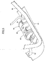
- a radiator 38 is disposed between the fuel tank 37 and the power unit P when viewed from the side, and a canister 40 collecting fuel vaporized within the fuel tank 37 is disposed in front of the radiator 38 in the vehicle fore-and-aft direction when viewed from the side.
- the canister 40 is disposed in front of the radiator 38 in the vehicle fore-and-aft direction when viewed from the side
- the internal combustion engine E of the power unit P is disposed to the rear of the radiator 38 in the vehicle fore-and-aft direction when viewed from the side
- the fuel tank 37 is disposed in front of the radiator 38 in the vehicle fore-and-aft direction when viewed from the side.
- the canister 40 is disposed on one side in the vehicle width direction of the fuel tank 37, in this embodiment on the left side of the fuel tank 37 in the vehicle width direction.
- the radiator 38 includes a radiator fan 39 on a back face, has an attitude in which a front face 38a of the radiator 38 faces the canister 40, that is, an attitude in which it is inclined upward to the front, and is disposed between the fuel tank 37 and the internal combustion engine E of the power unit P in the vehicle fore-and-aft direction.
- An upper part of the radiator 38 is supported by a first stay 41 provided on a rear part of the main frame 15, and a lower part of the radiator 38 is supported by a second stay 42 provided on the bracket 19.
- the footrest part 31 is formed on each of a pair of left and right side cowls 43 forming part of the vehicle body cover 33, and one of the side cowls 43 (in this embodiment the side cowl 43 on the left side in the vehicle width direction) is disposed so as to cover the canister 40 from the outside in the vehicle width direction. That is, the side cowl 43 on the left side in the vehicle width direction is disposed so as to sandwich the canister 40 between itself and the fuel tank 37 in the vehicle width direction.
- the pair of left and right footrest parts 31 are each supported from below by a support frame 45, front parts of the support frames 45 in the vehicle fore-and-aft direction are supported by a support stay 46 provided on a front part of the lower frame 16, and rear parts of the support frames 45 in the vehicle fore-and-aft direction are supported by a support plate 47 provided on the front end part of the rear frame 18.
- the canister 40 has a cylindrical external shape having opposite ends closed, and is disposed so that its central axis C is along the vehicle fore-and-aft direction.
- a band 48 made of a rubber is fitted at two locations spaced in the longitudinal direction of the canister 40 so as to be wound around the canister 40.
- a mounting plate 49 provided on the support frame 45 is inserted through a mounting projection portion 48a provided integrally with one position in the peripheral direction of the band 48, the support frame 45 thereby resiliently supporting the canister 40.
- the canister 40 in a state in which it is supported by the support frame 45 is disposed above the lower frame 16 when viewed from the side and on the inside in the vehicle width direction of the support frame 45 on the left side in the vehicle width direction.
- An air tube 50 and a drain tube 51 extend from a front end part in the vehicle fore-and-aft direction of the canister 40, the air tube 50 extending upward so as to open to the atmosphere and the drain tube 51 extending downward.
- a charge tube 52 and a purge tube 53 extend from a rear end part in the vehicle fore-and-aft direction of the canister 40, the charge tube 52 extending toward an upper part of the fuel tank 37 so as to guide vaporized fuel from the fuel tank 37 and the purge tube 53 extending rearward toward the air intake system 27 of the internal combustion engine E.
- a front cover 44 forming part of the vehicle body cover 33 is disposed in front of the fuel tank 37 and the canister 40 in the vehicle fore-and-aft direction when viewed from the side.
- a first louver 55 is provided in a middle part in the vehicle width direction of the front cover 44, and a second louver 56 is respectively provided on upper parts on opposite sides in the vehicle width direction of the front cover 44.
- the first louver 55 includes a plurality of vane portions 44a arranged in the vertical direction while being inclined downward to the rear and connectedly provided integrally with the front cover 44, and a slit 57 formed in the front cover 44 so as to be disposed beneath the vane portion 44a.
- the second louver 56 includes a plurality of vane portions 44b arranged in an up-and-down direction while being inclined downward to the rear and connectedly provided integrally with the front cover 44, and a slit 58 formed in the front cover 44 so as to be disposed beneath the vane portion 44b.
- the canister 40 which collects fuel vaporized within the fuel tank 37, is disposed in front of the radiator 38 in the vehicle fore-and-aft direction when viewed from the side, it is possible, by preventing heat from the radiator 38 from affecting the canister 40 when the two-wheeled motor vehicle is traveling, to enhance the effect in cooling the canister 40.
- the canister 40 which has a cylindrical external shape, is disposed so that its central axis C is along the vehicle fore-and-aft direction, it is possible to avoid any increase in the dimension in the vehicle width direction of the two-wheeled motor vehicle, thus enabling the canister 40 to be compactly disposed.
- the internal combustion engine E is disposed to the rear of the radiator 38 in the vehicle fore-and-aft direction when viewed from the side, it is possible, by preventing heat from the internal combustion engine E from affecting the canister 40, to further enhance the effect in cooling the canister 40.
- the fuel tank 37 is disposed in front of the radiator 38 in the vehicle fore-and-aft direction when viewed from the side, and the canister 40 is disposed on one side in the vehicle width direction of the fuel tank 37 (in this embodiment on the left side), the side wall of the fuel tank 37 functions as an air flow guide plate, air flow is easily gathered around the canister 40, and the ease of cooling the canister 40 improves.
- the side cowl 43 on the left side in the vehicle width direction is disposed so as to sandwich the canister 40 between itself and the fuel tank 37 in the vehicle width direction, the canister 40 is present between the fuel tank 37 and the side cowl 43, air that has been sucked in by the radiator fan 39 of the radiator 38 flows around the canister 40, and the ease of cooling the canister 40 improves.
- the first louver 55 which includes the plurality of vane portions 44a inclined downward to the rear toward the direction of the canister 40 and the slit 57 disposed beneath the vane portion 44a, is provided on a middle part in the vehicle width direction of the front cover 44 disposed in front of the canister 40 in the vehicle fore-and-aft direction when viewed from the side
- the second louver 56 which includes the plurality of vane portions 44b inclined downward to the rear toward the direction of the canister 40 and the slit 58 disposed beneath the vane portion 44b, is provided on an upper part on the left side in the vehicle width direction of the front cover 44, it becomes easy to make the air flow impinge on the canister 40, and the ease of cooling the canister 40 improves.
- the radiator 38 is supported on the vehicle body frame F in an attitude in which it is inclined upward to the rear so that the front face 38a faces the canister 40 side, it is possible to make the air flow sucked in by the radiator fan 39 pass around the canister 40 without stagnating, thus further improving the ease of cooling the canister 40.
- the canister 40 is supported on one of the pair of left and right support frames 45 (in this embodiment the support frame 45 on the left in the vehicle width direction) supporting from below the pair of left and right footrest parts 31 formed on the vehicle body cover 33, and the canister 40 is disposed above the lower frame 16 when viewed from the side and on the inside of the one support frame 45 in the vehicle width direction, it is possible to eliminate the necessity for a frame exclusively used for supporting the canister 40, thus making the structure for supporting the canister 40 compact while avoiding any increase in the number of components.
- the present invention may be applied not only to a two-wheeled motor vehicle but also widely to saddle-riding type vehicles, including a three-wheeled motor vehicle
Landscapes
- Engineering & Computer Science (AREA)
- Mechanical Engineering (AREA)
- Automatic Cycles, And Cycles In General (AREA)
Claims (8)
- Sattelaufsitzfahrzeug, in dem ein wassergekühlter Verbrennungsmotor (E), ein Kühler (38) und ein Kraftstofftank (37) an einem Fahrzeugrumpfrahmen (F) getragen sind, wobei ein Kanister (40), der in dem Kraftstofftank (37) verdampften Kraftstoff sammelt, in Fahrzeuglängsrichtung bei Betrachtung von einer Seite her, vor dem Kühler (38) angeordnet ist, wobei der Kanister (40) an einem Tragrahmen (45) über einem unteren Rahmen (16) an einer in Fahrzeugbreitenrichtung inneren Seite des Tragrahmens (45) getragen ist, wobei sich der Tragrahmen (45) in der Fahrzeuglängsrichtung erstreckt und an seinem vorderen Teil an einem vorderen Teil eines unteren Rahmens (16) des Fahrzeugrumpfrahmens (F) und an seinem hinteren Teil an einem vorderen Endteil eines Heckrahmens (18) des Fahrzeugrumpfrahmens (F) getragen ist.
- Das Sattelaufsitzfahrzeug nach Anspruch 1, wobei der Kanister (40), der eine zylindrische Außenform hat, derart angeordnet ist, dass seine Mittelachse (C) entlang der Fahrzeuglängsrichtung angeordnet ist.
- Das Sattelaufsitzfahrzeug nach Anspruch 1 oder 2, wobei der Verbrennungsmotor (E), in Fahrzeuglängsrichtung bei Betrachtung von der Seite, hinter dem Kühler (38) angeordnet ist.
- Das Sattelaufsitzfahrzeug nach einem der Ansprüche 1 bis 3, wobei der Kraftstofftank (37), in der Fahrzeuglängsrichtung bei Betrachtung von der Seite, vor dem Kühler (38) angeordnet ist, und der Kanister (40) in Fahrzeugbreitenrichtung an einer Seite des Kraftstofftanks (37) angeordnet ist.
- Das Sattelaufsitzfahrzeug nach einem der Ansprüche 1 bis 4, wobei eine eines Paars von Seitenverkleidungen (43), die Teil einer Fahrzeugrumpfabdeckung (33) sind, so angeordnet ist, dass der Kanister (40), in der Fahrzeugbreitenrichtung, zwischen der einen der Seitenverkleidungen (43) und dem Kraftstofftank (37) geschichtet ist.
- Das Sattelaufsitzfahrzeug nach einem der Ansprüche 1 bis 5, wobei eine Jalousie (55, 56), die eine Mehrzahl von Flügelabschnitten (44a, 44b), die nach hinten zu einer Richtung des Kanisters (40) abwärts geneigt sind, sowie einen Schlitz (57, 58), der unter den Flügelabschnitten (44a, 44b) angeordnet ist, aufweist, an einer Frontabdeckung (44) vorgesehen ist, die, in der Fahrzeuglängsrichtung bei Betrachtung von der Seite, vor dem Kanister (40) angeordnet ist.
- Das Sattelaufsitzfahrzeug nach einem der Ansprüche 1 bis 6, wobei der Kühler (38) an dem Fahrzeugrumpfrahmen (F) in einer Lage getragen ist, in der der Kühler (38) nach vorne hin aufwärts geneigt ist, sodass seine Vorderseite (38a) zur Kanister (40)-Seite weist.
- Das Sattelaufsitzfahrzeug nach einem der Ansprüche 1 bis 7, wobei der Fahrzeugrumpfrahmen (F) ein Kopfrohr (13), das Lenkstangen (12) lenkbar trägt, einen Unterzugrahmen (14), der sich von dem Kopfrohr (13) nach unten erstreckt, sowie ein Paar linker und rechter unterer Rahmen (16), die an einem unteren Teil des Unterzugrahmens (14) verbunden vorgesehen sind und sich nach hinten erstrecken, aufweist, wobei der Tragrahmen ein Paar linker und rechter Tragrahmen (45) aufweist, die ein Paar linker und rechter Fußrastenteile (31) von unten tragen, die an einer Fahrzeugrumpfabdeckung (33) ausgebildet sind, damit ein Fahrer seine oder ihre Füße darauf aufsetzt, wobei der Kanister (40) an einem des Paars linker und rechter Tragrahmen (45) getragen ist.
Applications Claiming Priority (2)
| Application Number | Priority Date | Filing Date | Title |
|---|---|---|---|
| JP2017047292 | 2017-03-13 | ||
| PCT/JP2018/002650 WO2018168223A1 (ja) | 2017-03-13 | 2018-01-29 | 鞍乗り型車両 |
Publications (3)
| Publication Number | Publication Date |
|---|---|
| EP3597518A1 EP3597518A1 (de) | 2020-01-22 |
| EP3597518A4 EP3597518A4 (de) | 2020-03-04 |
| EP3597518B1 true EP3597518B1 (de) | 2022-10-12 |
Family
ID=63522053
Family Applications (1)
| Application Number | Title | Priority Date | Filing Date |
|---|---|---|---|
| EP18766816.5A Active EP3597518B1 (de) | 2017-03-13 | 2018-01-29 | Sattelfahrzeug |
Country Status (6)
| Country | Link |
|---|---|
| US (1) | US11319012B2 (de) |
| EP (1) | EP3597518B1 (de) |
| JP (1) | JP6795681B2 (de) |
| CN (1) | CN110546061B (de) |
| BR (1) | BR112019018274A2 (de) |
| WO (1) | WO2018168223A1 (de) |
Families Citing this family (1)
| Publication number | Priority date | Publication date | Assignee | Title |
|---|---|---|---|---|
| JP7389079B2 (ja) * | 2021-03-30 | 2023-11-29 | 本田技研工業株式会社 | 鞍乗り型車両のラジエータ支持構造 |
Family Cites Families (22)
| Publication number | Priority date | Publication date | Assignee | Title |
|---|---|---|---|---|
| JP3340637B2 (ja) | 1997-01-21 | 2002-11-05 | 本田技研工業株式会社 | スクータ型自動二輪車の足載板とフロアスカートとの結合構造 |
| JP4371287B2 (ja) * | 2000-04-26 | 2009-11-25 | 本田技研工業株式会社 | スクータ型車両 |
| JP4381768B2 (ja) | 2003-10-10 | 2009-12-09 | 本田技研工業株式会社 | 自動二輪車の収納装置 |
| JP2008024285A (ja) * | 2006-06-23 | 2008-02-07 | Yamaha Motor Co Ltd | 鞍乗型車両 |
| JP4890532B2 (ja) | 2008-12-26 | 2012-03-07 | 本田技研工業株式会社 | 鞍乗型車両 |
| JP5323514B2 (ja) * | 2009-01-29 | 2013-10-23 | 本田技研工業株式会社 | 鞍乗り型車両のラジエーター取付構造 |
| JP2010203313A (ja) | 2009-03-03 | 2010-09-16 | Honda Motor Co Ltd | 不整地走行車両の蒸発燃料制御装置 |
| JP5312134B2 (ja) * | 2009-03-26 | 2013-10-09 | 本田技研工業株式会社 | 自動二輪車における蒸発燃料処理装置 |
| JP5312140B2 (ja) * | 2009-03-27 | 2013-10-09 | 本田技研工業株式会社 | 鞍乗り型車両におけるキャニスタ配置構造 |
| JP4861446B2 (ja) | 2009-03-30 | 2012-01-25 | 株式会社クボタ | 作業車 |
| JP2012001119A (ja) * | 2010-06-17 | 2012-01-05 | Suzuki Motor Corp | 自動二輪車のキャニスタ配置構造 |
| JP5715839B2 (ja) * | 2011-01-31 | 2015-05-13 | 本田技研工業株式会社 | 鞍乗り型車両 |
| JP5719264B2 (ja) | 2011-09-22 | 2015-05-13 | 本田技研工業株式会社 | 鞍乗型車両のキャニスタ配置構造 |
| JP5721599B2 (ja) | 2011-09-28 | 2015-05-20 | 本田技研工業株式会社 | 鞍乗型車両のキャニスタ配置構造 |
| JP5925547B2 (ja) * | 2012-03-22 | 2016-05-25 | 本田技研工業株式会社 | 鞍乗り型車両の導風構造 |
| JP5912718B2 (ja) * | 2012-03-22 | 2016-04-27 | 本田技研工業株式会社 | 鞍乗り型車両の防風構造 |
| JP5969232B2 (ja) * | 2012-03-22 | 2016-08-17 | 本田技研工業株式会社 | 鞍乗り型車両のラジエータホース配置構造 |
| JP5889685B2 (ja) * | 2012-03-22 | 2016-03-22 | 本田技研工業株式会社 | 鞍乗り型車両のキャニスター配置構造 |
| JP5926653B2 (ja) * | 2012-08-28 | 2016-05-25 | 本田技研工業株式会社 | 鞍乗り型車両の収納部構造 |
| JP6114048B2 (ja) | 2013-01-31 | 2017-04-12 | 本田技研工業株式会社 | 鞍乗り型車両のキャニスタ支持構造 |
| EP2765069B1 (de) | 2013-02-07 | 2020-04-22 | Yamaha Motor Co., Ltd. | Kanister |
| TW201607818A (zh) | 2014-08-21 | 2016-03-01 | Kwang Yang Motor Co | 機車油氣回收碳罐的配置構造 |
-
2018
- 2018-01-29 CN CN201880018093.7A patent/CN110546061B/zh active Active
- 2018-01-29 WO PCT/JP2018/002650 patent/WO2018168223A1/ja not_active Ceased
- 2018-01-29 EP EP18766816.5A patent/EP3597518B1/de active Active
- 2018-01-29 JP JP2019505748A patent/JP6795681B2/ja active Active
- 2018-01-29 US US16/489,525 patent/US11319012B2/en active Active
- 2018-01-29 BR BR112019018274-8A patent/BR112019018274A2/pt not_active Application Discontinuation
Also Published As
| Publication number | Publication date |
|---|---|
| WO2018168223A1 (ja) | 2018-09-20 |
| EP3597518A1 (de) | 2020-01-22 |
| CN110546061B (zh) | 2020-12-18 |
| JPWO2018168223A1 (ja) | 2019-11-07 |
| US11319012B2 (en) | 2022-05-03 |
| JP6795681B2 (ja) | 2020-12-02 |
| CN110546061A (zh) | 2019-12-06 |
| EP3597518A4 (de) | 2020-03-04 |
| BR112019018274A2 (pt) | 2020-07-14 |
| US20190375475A1 (en) | 2019-12-12 |
Similar Documents
| Publication | Publication Date | Title |
|---|---|---|
| JP4890532B2 (ja) | 鞍乗型車両 | |
| US8146693B2 (en) | Motorcycle and intake device thereof | |
| EP2952708B1 (de) | Luftreinigervorrichtung eines grätschsitzfahrzeugs | |
| JP5968348B2 (ja) | 車両のエアクリーナ装置 | |
| JP4661472B2 (ja) | 自動二輪車のカウリング | |
| EP3002204A1 (de) | Sattelfahrzeug | |
| EP3002189A2 (de) | Sattelfahrzeug | |
| JP5820443B2 (ja) | スクータ型車両 | |
| AU2018214145A1 (en) | Saddle riding vehicle | |
| US9328703B2 (en) | Air intake system of saddle-ride type vehicle | |
| JP6472482B2 (ja) | 鞍乗り型車両 | |
| JP2012187974A (ja) | 自動二輪車のカウリング装置 | |
| EP3597518B1 (de) | Sattelfahrzeug | |
| JP6202516B2 (ja) | 鞍乗り型車両 | |
| JP6179178B2 (ja) | スクータ型車両のエアクリーナ構造 | |
| JP6552626B2 (ja) | 鞍乗り型車両 | |
| JP6948399B2 (ja) | 鞍乗り型車両 | |
| JP6221126B2 (ja) | 鞍乗り型車両の吸気系構造 | |
| KR100891781B1 (ko) | 차량용 무단 변속기의 냉각 구조 | |
| JP2010058757A (ja) | 自動二輪車 | |
| JP3941803B2 (ja) | スクータ型車両の吸気装置 | |
| JP4786466B2 (ja) | エアクリーナ構造 | |
| JP2013174202A (ja) | 鞍乗型車両 | |
| WO2019044118A1 (ja) | エンジンの排気浄化装置 | |
| JP2019209898A (ja) | 鞍乗型車両 |
Legal Events
| Date | Code | Title | Description |
|---|---|---|---|
| STAA | Information on the status of an ep patent application or granted ep patent |
Free format text: STATUS: THE INTERNATIONAL PUBLICATION HAS BEEN MADE |
|
| PUAI | Public reference made under article 153(3) epc to a published international application that has entered the european phase |
Free format text: ORIGINAL CODE: 0009012 |
|
| STAA | Information on the status of an ep patent application or granted ep patent |
Free format text: STATUS: REQUEST FOR EXAMINATION WAS MADE |
|
| 17P | Request for examination filed |
Effective date: 20191002 |
|
| AK | Designated contracting states |
Kind code of ref document: A1 Designated state(s): AL AT BE BG CH CY CZ DE DK EE ES FI FR GB GR HR HU IE IS IT LI LT LU LV MC MK MT NL NO PL PT RO RS SE SI SK SM TR |
|
| AX | Request for extension of the european patent |
Extension state: BA ME |
|
| A4 | Supplementary search report drawn up and despatched |
Effective date: 20200130 |
|
| RIC1 | Information provided on ipc code assigned before grant |
Ipc: B62J 35/00 20060101ALI20200124BHEP Ipc: B62J 37/00 20060101AFI20200124BHEP Ipc: B62J 99/00 20200101ALI20200124BHEP Ipc: B62J 23/00 20060101ALI20200124BHEP |
|
| DAV | Request for validation of the european patent (deleted) | ||
| DAX | Request for extension of the european patent (deleted) | ||
| STAA | Information on the status of an ep patent application or granted ep patent |
Free format text: STATUS: EXAMINATION IS IN PROGRESS |
|
| 17Q | First examination report despatched |
Effective date: 20210820 |
|
| GRAP | Despatch of communication of intention to grant a patent |
Free format text: ORIGINAL CODE: EPIDOSNIGR1 |
|
| STAA | Information on the status of an ep patent application or granted ep patent |
Free format text: STATUS: GRANT OF PATENT IS INTENDED |
|
| INTG | Intention to grant announced |
Effective date: 20220513 |
|
| GRAS | Grant fee paid |
Free format text: ORIGINAL CODE: EPIDOSNIGR3 |
|
| GRAA | (expected) grant |
Free format text: ORIGINAL CODE: 0009210 |
|
| STAA | Information on the status of an ep patent application or granted ep patent |
Free format text: STATUS: THE PATENT HAS BEEN GRANTED |
|
| AK | Designated contracting states |
Kind code of ref document: B1 Designated state(s): AL AT BE BG CH CY CZ DE DK EE ES FI FR GB GR HR HU IE IS IT LI LT LU LV MC MK MT NL NO PL PT RO RS SE SI SK SM TR |
|
| REG | Reference to a national code |
Ref country code: GB Ref legal event code: FG4D |
|
| REG | Reference to a national code |
Ref country code: CH Ref legal event code: EP |
|
| REG | Reference to a national code |
Ref country code: DE Ref legal event code: R096 Ref document number: 602018041721 Country of ref document: DE |
|
| REG | Reference to a national code |
Ref country code: IE Ref legal event code: FG4D |
|
| REG | Reference to a national code |
Ref country code: AT Ref legal event code: REF Ref document number: 1524023 Country of ref document: AT Kind code of ref document: T Effective date: 20221115 |
|
| REG | Reference to a national code |
Ref country code: LT Ref legal event code: MG9D |
|
| REG | Reference to a national code |
Ref country code: NL Ref legal event code: MP Effective date: 20221012 |
|
| REG | Reference to a national code |
Ref country code: AT Ref legal event code: MK05 Ref document number: 1524023 Country of ref document: AT Kind code of ref document: T Effective date: 20221012 |
|
| PG25 | Lapsed in a contracting state [announced via postgrant information from national office to epo] |
Ref country code: NL Free format text: LAPSE BECAUSE OF FAILURE TO SUBMIT A TRANSLATION OF THE DESCRIPTION OR TO PAY THE FEE WITHIN THE PRESCRIBED TIME-LIMIT Effective date: 20221012 |
|
| PG25 | Lapsed in a contracting state [announced via postgrant information from national office to epo] |
Ref country code: SE Free format text: LAPSE BECAUSE OF FAILURE TO SUBMIT A TRANSLATION OF THE DESCRIPTION OR TO PAY THE FEE WITHIN THE PRESCRIBED TIME-LIMIT Effective date: 20221012 Ref country code: PT Free format text: LAPSE BECAUSE OF FAILURE TO SUBMIT A TRANSLATION OF THE DESCRIPTION OR TO PAY THE FEE WITHIN THE PRESCRIBED TIME-LIMIT Effective date: 20230213 Ref country code: NO Free format text: LAPSE BECAUSE OF FAILURE TO SUBMIT A TRANSLATION OF THE DESCRIPTION OR TO PAY THE FEE WITHIN THE PRESCRIBED TIME-LIMIT Effective date: 20230112 Ref country code: LT Free format text: LAPSE BECAUSE OF FAILURE TO SUBMIT A TRANSLATION OF THE DESCRIPTION OR TO PAY THE FEE WITHIN THE PRESCRIBED TIME-LIMIT Effective date: 20221012 Ref country code: FI Free format text: LAPSE BECAUSE OF FAILURE TO SUBMIT A TRANSLATION OF THE DESCRIPTION OR TO PAY THE FEE WITHIN THE PRESCRIBED TIME-LIMIT Effective date: 20221012 Ref country code: ES Free format text: LAPSE BECAUSE OF FAILURE TO SUBMIT A TRANSLATION OF THE DESCRIPTION OR TO PAY THE FEE WITHIN THE PRESCRIBED TIME-LIMIT Effective date: 20221012 Ref country code: AT Free format text: LAPSE BECAUSE OF FAILURE TO SUBMIT A TRANSLATION OF THE DESCRIPTION OR TO PAY THE FEE WITHIN THE PRESCRIBED TIME-LIMIT Effective date: 20221012 |
|
| PG25 | Lapsed in a contracting state [announced via postgrant information from national office to epo] |
Ref country code: RS Free format text: LAPSE BECAUSE OF FAILURE TO SUBMIT A TRANSLATION OF THE DESCRIPTION OR TO PAY THE FEE WITHIN THE PRESCRIBED TIME-LIMIT Effective date: 20221012 Ref country code: PL Free format text: LAPSE BECAUSE OF FAILURE TO SUBMIT A TRANSLATION OF THE DESCRIPTION OR TO PAY THE FEE WITHIN THE PRESCRIBED TIME-LIMIT Effective date: 20221012 Ref country code: LV Free format text: LAPSE BECAUSE OF FAILURE TO SUBMIT A TRANSLATION OF THE DESCRIPTION OR TO PAY THE FEE WITHIN THE PRESCRIBED TIME-LIMIT Effective date: 20221012 Ref country code: IS Free format text: LAPSE BECAUSE OF FAILURE TO SUBMIT A TRANSLATION OF THE DESCRIPTION OR TO PAY THE FEE WITHIN THE PRESCRIBED TIME-LIMIT Effective date: 20230212 Ref country code: HR Free format text: LAPSE BECAUSE OF FAILURE TO SUBMIT A TRANSLATION OF THE DESCRIPTION OR TO PAY THE FEE WITHIN THE PRESCRIBED TIME-LIMIT Effective date: 20221012 Ref country code: GR Free format text: LAPSE BECAUSE OF FAILURE TO SUBMIT A TRANSLATION OF THE DESCRIPTION OR TO PAY THE FEE WITHIN THE PRESCRIBED TIME-LIMIT Effective date: 20230113 |
|
| REG | Reference to a national code |
Ref country code: DE Ref legal event code: R097 Ref document number: 602018041721 Country of ref document: DE |
|
| PG25 | Lapsed in a contracting state [announced via postgrant information from national office to epo] |
Ref country code: SM Free format text: LAPSE BECAUSE OF FAILURE TO SUBMIT A TRANSLATION OF THE DESCRIPTION OR TO PAY THE FEE WITHIN THE PRESCRIBED TIME-LIMIT Effective date: 20221012 Ref country code: RO Free format text: LAPSE BECAUSE OF FAILURE TO SUBMIT A TRANSLATION OF THE DESCRIPTION OR TO PAY THE FEE WITHIN THE PRESCRIBED TIME-LIMIT Effective date: 20221012 Ref country code: EE Free format text: LAPSE BECAUSE OF FAILURE TO SUBMIT A TRANSLATION OF THE DESCRIPTION OR TO PAY THE FEE WITHIN THE PRESCRIBED TIME-LIMIT Effective date: 20221012 Ref country code: DK Free format text: LAPSE BECAUSE OF FAILURE TO SUBMIT A TRANSLATION OF THE DESCRIPTION OR TO PAY THE FEE WITHIN THE PRESCRIBED TIME-LIMIT Effective date: 20221012 Ref country code: CZ Free format text: LAPSE BECAUSE OF FAILURE TO SUBMIT A TRANSLATION OF THE DESCRIPTION OR TO PAY THE FEE WITHIN THE PRESCRIBED TIME-LIMIT Effective date: 20221012 |
|
| PLBE | No opposition filed within time limit |
Free format text: ORIGINAL CODE: 0009261 |
|
| REG | Reference to a national code |
Ref country code: DE Ref legal event code: R084 Ref document number: 602018041721 Country of ref document: DE |
|
| STAA | Information on the status of an ep patent application or granted ep patent |
Free format text: STATUS: NO OPPOSITION FILED WITHIN TIME LIMIT |
|
| PG25 | Lapsed in a contracting state [announced via postgrant information from national office to epo] |
Ref country code: SK Free format text: LAPSE BECAUSE OF FAILURE TO SUBMIT A TRANSLATION OF THE DESCRIPTION OR TO PAY THE FEE WITHIN THE PRESCRIBED TIME-LIMIT Effective date: 20221012 Ref country code: AL Free format text: LAPSE BECAUSE OF FAILURE TO SUBMIT A TRANSLATION OF THE DESCRIPTION OR TO PAY THE FEE WITHIN THE PRESCRIBED TIME-LIMIT Effective date: 20221012 |
|
| REG | Reference to a national code |
Ref country code: CH Ref legal event code: PL |
|
| 26N | No opposition filed |
Effective date: 20230713 |
|
| GBPC | Gb: european patent ceased through non-payment of renewal fee |
Effective date: 20230129 |
|
| PG25 | Lapsed in a contracting state [announced via postgrant information from national office to epo] |
Ref country code: LU Free format text: LAPSE BECAUSE OF NON-PAYMENT OF DUE FEES Effective date: 20230129 |
|
| REG | Reference to a national code |
Ref country code: BE Ref legal event code: MM Effective date: 20230131 |
|
| PG25 | Lapsed in a contracting state [announced via postgrant information from national office to epo] |
Ref country code: LI Free format text: LAPSE BECAUSE OF NON-PAYMENT OF DUE FEES Effective date: 20230131 Ref country code: GB Free format text: LAPSE BECAUSE OF NON-PAYMENT OF DUE FEES Effective date: 20230129 Ref country code: CH Free format text: LAPSE BECAUSE OF NON-PAYMENT OF DUE FEES Effective date: 20230131 |
|
| PG25 | Lapsed in a contracting state [announced via postgrant information from national office to epo] |
Ref country code: SI Free format text: LAPSE BECAUSE OF FAILURE TO SUBMIT A TRANSLATION OF THE DESCRIPTION OR TO PAY THE FEE WITHIN THE PRESCRIBED TIME-LIMIT Effective date: 20221012 Ref country code: FR Free format text: LAPSE BECAUSE OF NON-PAYMENT OF DUE FEES Effective date: 20230131 Ref country code: BE Free format text: LAPSE BECAUSE OF NON-PAYMENT OF DUE FEES Effective date: 20230131 |
|
| PG25 | Lapsed in a contracting state [announced via postgrant information from national office to epo] |
Ref country code: IE Free format text: LAPSE BECAUSE OF NON-PAYMENT OF DUE FEES Effective date: 20230129 |
|
| PGFP | Annual fee paid to national office [announced via postgrant information from national office to epo] |
Ref country code: DE Payment date: 20231205 Year of fee payment: 7 |
|
| PG25 | Lapsed in a contracting state [announced via postgrant information from national office to epo] |
Ref country code: IT Free format text: LAPSE BECAUSE OF FAILURE TO SUBMIT A TRANSLATION OF THE DESCRIPTION OR TO PAY THE FEE WITHIN THE PRESCRIBED TIME-LIMIT Effective date: 20221012 |
|
| PG25 | Lapsed in a contracting state [announced via postgrant information from national office to epo] |
Ref country code: MC Free format text: LAPSE BECAUSE OF FAILURE TO SUBMIT A TRANSLATION OF THE DESCRIPTION OR TO PAY THE FEE WITHIN THE PRESCRIBED TIME-LIMIT Effective date: 20221012 |
|
| PG25 | Lapsed in a contracting state [announced via postgrant information from national office to epo] |
Ref country code: MC Free format text: LAPSE BECAUSE OF FAILURE TO SUBMIT A TRANSLATION OF THE DESCRIPTION OR TO PAY THE FEE WITHIN THE PRESCRIBED TIME-LIMIT Effective date: 20221012 |
|
| PG25 | Lapsed in a contracting state [announced via postgrant information from national office to epo] |
Ref country code: BG Free format text: LAPSE BECAUSE OF FAILURE TO SUBMIT A TRANSLATION OF THE DESCRIPTION OR TO PAY THE FEE WITHIN THE PRESCRIBED TIME-LIMIT Effective date: 20221012 |
|
| PG25 | Lapsed in a contracting state [announced via postgrant information from national office to epo] |
Ref country code: BG Free format text: LAPSE BECAUSE OF FAILURE TO SUBMIT A TRANSLATION OF THE DESCRIPTION OR TO PAY THE FEE WITHIN THE PRESCRIBED TIME-LIMIT Effective date: 20221012 |
|
| PG25 | Lapsed in a contracting state [announced via postgrant information from national office to epo] |
Ref country code: CY Free format text: LAPSE BECAUSE OF FAILURE TO SUBMIT A TRANSLATION OF THE DESCRIPTION OR TO PAY THE FEE WITHIN THE PRESCRIBED TIME-LIMIT; INVALID AB INITIO Effective date: 20180129 |
|
| REG | Reference to a national code |
Ref country code: DE Ref legal event code: R119 Ref document number: 602018041721 Country of ref document: DE |
|
| PG25 | Lapsed in a contracting state [announced via postgrant information from national office to epo] |
Ref country code: HU Free format text: LAPSE BECAUSE OF FAILURE TO SUBMIT A TRANSLATION OF THE DESCRIPTION OR TO PAY THE FEE WITHIN THE PRESCRIBED TIME-LIMIT; INVALID AB INITIO Effective date: 20180129 |
|
| PG25 | Lapsed in a contracting state [announced via postgrant information from national office to epo] |
Ref country code: DE Free format text: LAPSE BECAUSE OF NON-PAYMENT OF DUE FEES Effective date: 20250801 |
|
| PG25 | Lapsed in a contracting state [announced via postgrant information from national office to epo] |
Ref country code: TR Free format text: LAPSE BECAUSE OF FAILURE TO SUBMIT A TRANSLATION OF THE DESCRIPTION OR TO PAY THE FEE WITHIN THE PRESCRIBED TIME-LIMIT Effective date: 20221012 |