EP3594003B1 - Dispositif de décharge de liquide et procédé de commande du dispositif de décharge de liquide - Google Patents
Dispositif de décharge de liquide et procédé de commande du dispositif de décharge de liquide Download PDFInfo
- Publication number
- EP3594003B1 EP3594003B1 EP19185374.6A EP19185374A EP3594003B1 EP 3594003 B1 EP3594003 B1 EP 3594003B1 EP 19185374 A EP19185374 A EP 19185374A EP 3594003 B1 EP3594003 B1 EP 3594003B1
- Authority
- EP
- European Patent Office
- Prior art keywords
- liquid
- medium
- carriage
- area
- nozzle surface
- Prior art date
- Legal status (The legal status is an assumption and is not a legal conclusion. Google has not performed a legal analysis and makes no representation as to the accuracy of the status listed.)
- Active
Links
- 239000007788 liquid Substances 0.000 title claims description 428
- 238000000034 method Methods 0.000 title claims description 29
- 238000007639 printing Methods 0.000 description 47
- 238000012423 maintenance Methods 0.000 description 37
- 238000012545 processing Methods 0.000 description 23
- 238000001035 drying Methods 0.000 description 18
- 230000008569 process Effects 0.000 description 18
- 238000004140 cleaning Methods 0.000 description 15
- 238000007599 discharging Methods 0.000 description 11
- 238000005520 cutting process Methods 0.000 description 9
- 238000003860 storage Methods 0.000 description 8
- 238000011144 upstream manufacturing Methods 0.000 description 8
- 238000001514 detection method Methods 0.000 description 4
- 230000007246 mechanism Effects 0.000 description 4
- 230000008901 benefit Effects 0.000 description 3
- 230000006870 function Effects 0.000 description 3
- 238000003825 pressing Methods 0.000 description 3
- 238000007790 scraping Methods 0.000 description 3
- 229920003002 synthetic resin Polymers 0.000 description 3
- 239000000057 synthetic resin Substances 0.000 description 3
- 206010000210 abortion Diseases 0.000 description 2
- 230000000052 comparative effect Effects 0.000 description 2
- 229920001971 elastomer Polymers 0.000 description 2
- 238000002347 injection Methods 0.000 description 2
- 239000007924 injection Substances 0.000 description 2
- 230000008961 swelling Effects 0.000 description 2
- 238000012546 transfer Methods 0.000 description 2
- 230000009471 action Effects 0.000 description 1
- 238000005452 bending Methods 0.000 description 1
- 230000015556 catabolic process Effects 0.000 description 1
- 239000003086 colorant Substances 0.000 description 1
- 239000000470 constituent Substances 0.000 description 1
- 238000006731 degradation reaction Methods 0.000 description 1
- 230000006866 deterioration Effects 0.000 description 1
- 238000010586 diagram Methods 0.000 description 1
- 239000013013 elastic material Substances 0.000 description 1
- 239000000806 elastomer Substances 0.000 description 1
- 238000007667 floating Methods 0.000 description 1
- 239000011888 foil Substances 0.000 description 1
- 239000012943 hotmelt Substances 0.000 description 1
- 239000011344 liquid material Substances 0.000 description 1
- 239000000463 material Substances 0.000 description 1
- 230000005499 meniscus Effects 0.000 description 1
- 239000002184 metal Substances 0.000 description 1
- 239000000203 mixture Substances 0.000 description 1
- 239000004745 nonwoven fabric Substances 0.000 description 1
- 239000002245 particle Substances 0.000 description 1
- 229920005989 resin Polymers 0.000 description 1
- 239000011347 resin Substances 0.000 description 1
- 230000000284 resting effect Effects 0.000 description 1
- 238000005096 rolling process Methods 0.000 description 1
- 239000007787 solid Substances 0.000 description 1
- 238000013519 translation Methods 0.000 description 1
- 239000002759 woven fabric Substances 0.000 description 1
Images


Classifications
-
- B—PERFORMING OPERATIONS; TRANSPORTING
- B41—PRINTING; LINING MACHINES; TYPEWRITERS; STAMPS
- B41J—TYPEWRITERS; SELECTIVE PRINTING MECHANISMS, i.e. MECHANISMS PRINTING OTHERWISE THAN FROM A FORME; CORRECTION OF TYPOGRAPHICAL ERRORS
- B41J2/00—Typewriters or selective printing mechanisms characterised by the printing or marking process for which they are designed
- B41J2/005—Typewriters or selective printing mechanisms characterised by the printing or marking process for which they are designed characterised by bringing liquid or particles selectively into contact with a printing material
- B41J2/01—Ink jet
- B41J2/135—Nozzles
- B41J2/145—Arrangement thereof
- B41J2/15—Arrangement thereof for serial printing
-
- B—PERFORMING OPERATIONS; TRANSPORTING
- B41—PRINTING; LINING MACHINES; TYPEWRITERS; STAMPS
- B41J—TYPEWRITERS; SELECTIVE PRINTING MECHANISMS, i.e. MECHANISMS PRINTING OTHERWISE THAN FROM A FORME; CORRECTION OF TYPOGRAPHICAL ERRORS
- B41J2/00—Typewriters or selective printing mechanisms characterised by the printing or marking process for which they are designed
- B41J2/005—Typewriters or selective printing mechanisms characterised by the printing or marking process for which they are designed characterised by bringing liquid or particles selectively into contact with a printing material
- B41J2/01—Ink jet
- B41J2/17—Ink jet characterised by ink handling
- B41J2/175—Ink supply systems ; Circuit parts therefor
- B41J2/17503—Ink cartridges
- B41J2/17506—Refilling of the cartridge
-
- B—PERFORMING OPERATIONS; TRANSPORTING
- B41—PRINTING; LINING MACHINES; TYPEWRITERS; STAMPS
- B41J—TYPEWRITERS; SELECTIVE PRINTING MECHANISMS, i.e. MECHANISMS PRINTING OTHERWISE THAN FROM A FORME; CORRECTION OF TYPOGRAPHICAL ERRORS
- B41J11/00—Devices or arrangements of selective printing mechanisms, e.g. ink-jet printers or thermal printers, for supporting or handling copy material in sheet or web form
- B41J11/007—Conveyor belts or like feeding devices
-
- B—PERFORMING OPERATIONS; TRANSPORTING
- B41—PRINTING; LINING MACHINES; TYPEWRITERS; STAMPS
- B41J—TYPEWRITERS; SELECTIVE PRINTING MECHANISMS, i.e. MECHANISMS PRINTING OTHERWISE THAN FROM A FORME; CORRECTION OF TYPOGRAPHICAL ERRORS
- B41J11/00—Devices or arrangements of selective printing mechanisms, e.g. ink-jet printers or thermal printers, for supporting or handling copy material in sheet or web form
- B41J11/36—Blanking or long feeds; Feeding to a particular line, e.g. by rotation of platen or feed roller
- B41J11/42—Controlling printing material conveyance for accurate alignment of the printing material with the printhead; Print registering
-
- B—PERFORMING OPERATIONS; TRANSPORTING
- B41—PRINTING; LINING MACHINES; TYPEWRITERS; STAMPS
- B41J—TYPEWRITERS; SELECTIVE PRINTING MECHANISMS, i.e. MECHANISMS PRINTING OTHERWISE THAN FROM A FORME; CORRECTION OF TYPOGRAPHICAL ERRORS
- B41J13/00—Devices or arrangements of selective printing mechanisms, e.g. ink-jet printers or thermal printers, specially adapted for supporting or handling copy material in short lengths, e.g. sheets
- B41J13/0009—Devices or arrangements of selective printing mechanisms, e.g. ink-jet printers or thermal printers, specially adapted for supporting or handling copy material in short lengths, e.g. sheets control of the transport of the copy material
- B41J13/0018—Devices or arrangements of selective printing mechanisms, e.g. ink-jet printers or thermal printers, specially adapted for supporting or handling copy material in short lengths, e.g. sheets control of the transport of the copy material in the sheet input section of automatic paper handling systems
-
- B—PERFORMING OPERATIONS; TRANSPORTING
- B41—PRINTING; LINING MACHINES; TYPEWRITERS; STAMPS
- B41J—TYPEWRITERS; SELECTIVE PRINTING MECHANISMS, i.e. MECHANISMS PRINTING OTHERWISE THAN FROM A FORME; CORRECTION OF TYPOGRAPHICAL ERRORS
- B41J2/00—Typewriters or selective printing mechanisms characterised by the printing or marking process for which they are designed
- B41J2/005—Typewriters or selective printing mechanisms characterised by the printing or marking process for which they are designed characterised by bringing liquid or particles selectively into contact with a printing material
- B41J2/01—Ink jet
- B41J2/015—Ink jet characterised by the jet generation process
- B41J2/04—Ink jet characterised by the jet generation process generating single droplets or particles on demand
-
- B—PERFORMING OPERATIONS; TRANSPORTING
- B41—PRINTING; LINING MACHINES; TYPEWRITERS; STAMPS
- B41J—TYPEWRITERS; SELECTIVE PRINTING MECHANISMS, i.e. MECHANISMS PRINTING OTHERWISE THAN FROM A FORME; CORRECTION OF TYPOGRAPHICAL ERRORS
- B41J2/00—Typewriters or selective printing mechanisms characterised by the printing or marking process for which they are designed
- B41J2/005—Typewriters or selective printing mechanisms characterised by the printing or marking process for which they are designed characterised by bringing liquid or particles selectively into contact with a printing material
- B41J2/01—Ink jet
- B41J2/135—Nozzles
- B41J2/165—Prevention or detection of nozzle clogging, e.g. cleaning, capping or moistening for nozzles
- B41J2/16505—Caps, spittoons or covers for cleaning or preventing drying out
- B41J2/16508—Caps, spittoons or covers for cleaning or preventing drying out connected with the printer frame
- B41J2/16511—Constructions for cap positioning
-
- B—PERFORMING OPERATIONS; TRANSPORTING
- B41—PRINTING; LINING MACHINES; TYPEWRITERS; STAMPS
- B41J—TYPEWRITERS; SELECTIVE PRINTING MECHANISMS, i.e. MECHANISMS PRINTING OTHERWISE THAN FROM A FORME; CORRECTION OF TYPOGRAPHICAL ERRORS
- B41J2/00—Typewriters or selective printing mechanisms characterised by the printing or marking process for which they are designed
- B41J2/005—Typewriters or selective printing mechanisms characterised by the printing or marking process for which they are designed characterised by bringing liquid or particles selectively into contact with a printing material
- B41J2/01—Ink jet
- B41J2/135—Nozzles
- B41J2/165—Prevention or detection of nozzle clogging, e.g. cleaning, capping or moistening for nozzles
- B41J2/16517—Cleaning of print head nozzles
- B41J2/1652—Cleaning of print head nozzles by driving a fluid through the nozzles to the outside thereof, e.g. by applying pressure to the inside or vacuum at the outside of the print head
- B41J2/16526—Cleaning of print head nozzles by driving a fluid through the nozzles to the outside thereof, e.g. by applying pressure to the inside or vacuum at the outside of the print head by applying pressure only
-
- B—PERFORMING OPERATIONS; TRANSPORTING
- B41—PRINTING; LINING MACHINES; TYPEWRITERS; STAMPS
- B41J—TYPEWRITERS; SELECTIVE PRINTING MECHANISMS, i.e. MECHANISMS PRINTING OTHERWISE THAN FROM A FORME; CORRECTION OF TYPOGRAPHICAL ERRORS
- B41J2/00—Typewriters or selective printing mechanisms characterised by the printing or marking process for which they are designed
- B41J2/005—Typewriters or selective printing mechanisms characterised by the printing or marking process for which they are designed characterised by bringing liquid or particles selectively into contact with a printing material
- B41J2/01—Ink jet
- B41J2/135—Nozzles
- B41J2/165—Prevention or detection of nozzle clogging, e.g. cleaning, capping or moistening for nozzles
- B41J2/16517—Cleaning of print head nozzles
- B41J2/16535—Cleaning of print head nozzles using wiping constructions
-
- B—PERFORMING OPERATIONS; TRANSPORTING
- B41—PRINTING; LINING MACHINES; TYPEWRITERS; STAMPS
- B41J—TYPEWRITERS; SELECTIVE PRINTING MECHANISMS, i.e. MECHANISMS PRINTING OTHERWISE THAN FROM A FORME; CORRECTION OF TYPOGRAPHICAL ERRORS
- B41J2/00—Typewriters or selective printing mechanisms characterised by the printing or marking process for which they are designed
- B41J2/005—Typewriters or selective printing mechanisms characterised by the printing or marking process for which they are designed characterised by bringing liquid or particles selectively into contact with a printing material
- B41J2/01—Ink jet
- B41J2/17—Ink jet characterised by ink handling
- B41J2/175—Ink supply systems ; Circuit parts therefor
- B41J2/17503—Ink cartridges
- B41J2/17506—Refilling of the cartridge
- B41J2/17509—Whilst mounted in the printer
-
- B—PERFORMING OPERATIONS; TRANSPORTING
- B41—PRINTING; LINING MACHINES; TYPEWRITERS; STAMPS
- B41J—TYPEWRITERS; SELECTIVE PRINTING MECHANISMS, i.e. MECHANISMS PRINTING OTHERWISE THAN FROM A FORME; CORRECTION OF TYPOGRAPHICAL ERRORS
- B41J2/00—Typewriters or selective printing mechanisms characterised by the printing or marking process for which they are designed
- B41J2/005—Typewriters or selective printing mechanisms characterised by the printing or marking process for which they are designed characterised by bringing liquid or particles selectively into contact with a printing material
- B41J2/01—Ink jet
- B41J2/17—Ink jet characterised by ink handling
- B41J2/175—Ink supply systems ; Circuit parts therefor
- B41J2/17503—Ink cartridges
- B41J2/1752—Mounting within the printer
-
- B—PERFORMING OPERATIONS; TRANSPORTING
- B41—PRINTING; LINING MACHINES; TYPEWRITERS; STAMPS
- B41J—TYPEWRITERS; SELECTIVE PRINTING MECHANISMS, i.e. MECHANISMS PRINTING OTHERWISE THAN FROM A FORME; CORRECTION OF TYPOGRAPHICAL ERRORS
- B41J2/00—Typewriters or selective printing mechanisms characterised by the printing or marking process for which they are designed
- B41J2/005—Typewriters or selective printing mechanisms characterised by the printing or marking process for which they are designed characterised by bringing liquid or particles selectively into contact with a printing material
- B41J2/01—Ink jet
- B41J2/17—Ink jet characterised by ink handling
- B41J2/175—Ink supply systems ; Circuit parts therefor
- B41J2/17566—Ink level or ink residue control
-
- B—PERFORMING OPERATIONS; TRANSPORTING
- B41—PRINTING; LINING MACHINES; TYPEWRITERS; STAMPS
- B41J—TYPEWRITERS; SELECTIVE PRINTING MECHANISMS, i.e. MECHANISMS PRINTING OTHERWISE THAN FROM A FORME; CORRECTION OF TYPOGRAPHICAL ERRORS
- B41J25/00—Actions or mechanisms not otherwise provided for
- B41J25/34—Bodily-changeable print heads or carriages
-
- B—PERFORMING OPERATIONS; TRANSPORTING
- B41—PRINTING; LINING MACHINES; TYPEWRITERS; STAMPS
- B41J—TYPEWRITERS; SELECTIVE PRINTING MECHANISMS, i.e. MECHANISMS PRINTING OTHERWISE THAN FROM A FORME; CORRECTION OF TYPOGRAPHICAL ERRORS
- B41J29/00—Details of, or accessories for, typewriters or selective printing mechanisms not otherwise provided for
- B41J29/12—Guards, shields or dust excluders
- B41J29/13—Cases or covers
-
- B—PERFORMING OPERATIONS; TRANSPORTING
- B41—PRINTING; LINING MACHINES; TYPEWRITERS; STAMPS
- B41J—TYPEWRITERS; SELECTIVE PRINTING MECHANISMS, i.e. MECHANISMS PRINTING OTHERWISE THAN FROM A FORME; CORRECTION OF TYPOGRAPHICAL ERRORS
- B41J29/00—Details of, or accessories for, typewriters or selective printing mechanisms not otherwise provided for
- B41J29/38—Drives, motors, controls or automatic cut-off devices for the entire printing mechanism
Definitions
- the discharge head 21 is supported by the carriage 20, and reciprocates in the X-axis direction together with the carriage 20.
- the discharge head 21 has a nozzle surface 21A on which nozzles N open.
- Nozzles N is for discharging the liquid such as the ink. It should be noted that although four nozzles N are schematically illustrated in FIG. 3 , a predetermined number of nozzles N in a range of 100 through 500 are disposed in, for example, the Y-axis direction.
- the carriage 20 waits at the home position HP shown in FIG. 4 and set in one end part in the X-axis direction in a scanning range of the carriage 20 when printing is not performed.
- the carriage 20 can move in a range of the moving area MA from the home position indicated by the solid lines in FIG. 4 to an anti-home position indicated by the dashed-two dotted lines in FIG. 4 .
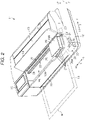
- the support stage 42 In the housing 12, there is disposed the support stage 42 at a position corresponding to an area below the moving path of the carriage 20. Due to the rotational drive of the feed shaft 36 by the feed motor 37, the feed section 35 feeds the medium M from the roll body R installed in the feed shaft 36 toward the downstream in the conveying path.
- the first position P1 of the present embodiment is also the position of the carriage 20 where the nozzle surface 21A is opposed to the area PCA between the print processing area PA and the cap 29.
- the nozzle surface 21A does not overlap the medium M in the vertical direction Z irrespective of the size of the medium M.
- the nozzle surface 21A does not overlap the cap 29 in the vertical direction Z.
- the medium M is moved toward the upstream in the conveying path.
- the medium M is conveyed in the direction toward the -Y side opposite to the direction toward the +Y side which is the conveying direction of the medium M in the evacuation operation.
- the control section 60 conveys the medium M toward the -Y side as much as the conveying length corresponding to the conveying length FL of the conveyance of the medium M toward the +Y side in the evacuation operation in the Y-axis direction.
- the medium M is returned to the original conveyance position when the printing is aborted due to the liquid end.
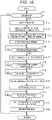
- control when replacing the cartridge is the control for helping the replacement of the liquid cartridge 27 by the user, and at the same time suppressing degradation of the print quality due to the abort of printing when the cartridge replacement is performed in the process of the printing.
- the control when replacing the cartridge includes moving the carriage 20 to the first position P1 where the cartridge replacement is performed, the evacuation operation of the medium M, and so on.
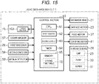
- the control section 60 judges whether or not the replacement of the liquid cartridge 27 has been detected.
- the control section 60 judges whether or not the replacement of the liquid cartridge 27 has been detected after the evacuation operation.
- the control section 60 detects the replacement of the liquid cartridge 27 using electrical disconnection and reconnection to the storage elements of the respective liquid cartridges 27 around the replacement of the cartridge.
- a liquid discharge device according to claim 1 is disclosed.
- Claim 2 discloses a further preferred embodiment of the invention according to claim 1.
- the inside of the housing is higher in humidity compared to the outside of the housing.
- a method of controlling a liquid discharge device according to claim 8 is disclosed. According to this method, substantially the same functions and advantages as those of the liquid discharge device according to claim 1 are obtained.
Landscapes
- Ink Jet (AREA)
Claims (8)
- Dispositif de décharge de liquide (11) comprenant :une tête de décharge (21) configurée pour décharger un liquide tel que de l'encre de couleur sur un support (m) transporté ;un chariot (20) sur lequel sont montés la tête de décharge (21) et une pluralité de réservoirs à liquide (27), configuré pour se déplacer dans une première direction axiale (x), chaque réservoir à liquide (27) étant configuré pour contenir le liquide destiné à être fourni à la tête de décharge (21) ;un capuchon (29) disposé à l'extérieur d'une zone de transport (FA) dans la première direction axiale (x), et configuré pour être en contact avec une surface de buses (21A) de la tête de décharge (21), la surface de buses (21A) étant une surface sur laquelle débouche une buse (N), et la zone de transport (FA) étant une plage dans laquelle le support (m) est transporté ; etune section de commande (60) configurée pour commander le déplacement du chariot (20), dans lequel une pluralité de colonnes de buses (NR) sont disposées sur la surface de buses (21A),les colonnes (NR) sont constituées respectivement d'un groupe de buses (N), et chaque colonne de buses (NR) correspond à l'un parmi la pluralité de réservoirs d'encre (27),caractérisé en ce quela section de commande (60) place le chariot (20) à une première position (P1) où l'ensemble de la surface de buses (21A) est tourné vers une zone (PCA) entre l'extrémité latérale (M1) côté capuchon (29) dans la zone de transport (FA) du support (m) et une extrémité latérale (C1) côté zone de transport (FA) du capuchon (29) dans la première direction axiale (x) lors d'un remplacement de l'un des réservoirs à liquide (27) ou d'une recharge de l'un des réservoirs à liquide (27) avec le liquide,dans lequel, dans le cas d'une recharge d'un réservoir à liquide pendant que le réservoir à liquide est maintenu monté sur le chariot, le réservoir à liquide comporte une entrée pour l'injection du liquide.
- Dispositif de décharge de liquide selon la revendication 1, comprenant en outre :une saillie (51) faisant saillie à partir d'un cadre inférieur (19), configurée pour être en contact avec une surface de chariot (20C) du chariot (20) opposée au cadre inférieur (19) lorsque le chariot (20) se trouve à la première position (P1), la surface de chariot (20C) étant configurée pour être tournée vers le support (m) transporté, dans lequelun espace (GH) est formé entre la surface de buses (21A) et une surface supérieure du cadre inférieur (19) opposée à la surface de buses (21A) lorsque la surface de chariot (20C) et la saillie (51) sont en contact l'une avec l'autre.
- Dispositif de décharge de liquide selon la revendication 1 ou la revendication 2, comprenant en outre :une section de transport (40) configurée pour transporter le support (m) dans une deuxième direction axiale (y), la deuxième direction axiale (y) coupant la première direction axiale (x), dans lequella section de commande (60) effectue une opération d'évacuation consistant à transporter le support (m) pour évacuer une zone (IA), du support, sur lequel le liquide a été déchargé par la tête de décharge (21) le long de la deuxième direction axiale (y) lors du remplacement du réservoir à liquide (27) et de la recharge du réservoir à liquide (27) avec le liquide, etune longueur de transport (FL) du support (m) dans l'opération d'évacuation est supérieure à une dimension dans la deuxième direction axiale (y) de la surface de buses (21A).
- Dispositif de décharge de liquide selon la revendication 3, dans lequella section de commande (60) place le chariot (20) à la première position (P1) lors du remplacement du réservoir à liquide (27), etlorsque la section de commande (60) a détecté que le remplacement du réservoir à liquide (27) est terminé après l'opération d'évacuation, la section de commande (60) transporte le support (m) dans une direction opposée à une direction de transport du support (m) dans l'opération d'évacuation, et décharge le liquide sur le support (m) après le transport du support (m) dans la direction opposée.
- Dispositif de décharge de liquide selon la revendication 3, dans lequella section de commande (60) place la chariot (20) à la première position (P1) lors de la recharge du réservoir à liquide (27), etlorsque la section de commande (60) a détecté que la recharge du réservoir à liquide (27) est terminée après l'opération d'évacuation, la section de commande (60) transporte le support (m) dans une direction opposée à une direction de transport du support (m) dans l'opération d'évacuation, et décharge le liquide sur le support (m) après le transport du support (m) dans la direction opposée.
- Dispositif de décharge de liquide selon l'une quelconque des revendications 3 à 5, dans lequel
la section de commande (60), dans l'opération d'évacuation, place la zone (IA) sur laquelle le liquide a été déchargé à la position située dans une première direction par rapport à une zone (HA) opposée à la surface de buses dans la deuxième direction axiale (y), la zone (HA) opposée à la surface de buses étant une zone dans laquelle la surface de buses (21A) est configurée pour être opposée au support (m) transporté, et la première direction étant opposée à une direction, le long de la deuxième direction axiale (y), allant de la zone (HA) opposée à la surface de buses vers une zone sur laquelle le liquide n'a pas encore été déchargé par l'unité de décharge. - Dispositif de décharge de liquide selon l'une quelconque des revendications 3 à 6, comprenant en outre :un boîtier (12) comportant une sortie (16) par laquelle le support (m) sur lequel le liquide a été déchargé, dans lequella section de commande (60), dans l'opération d'évacuation, place la zone sur laquelle le liquide a été déchargé à l'extérieur du boîtier par rapport à la sortie.
- Procédé de commande d'un dispositif de décharge de liquide incluant une tête de décharge (21) configurée pour décharger un liquide tel que de l'encre de couleur sur un support (m) transporté, un capuchon (29) disposé à l'extérieur d'une zone de transport dans la première direction axiale, et configuré pour être en contact avec une surface de buses (21A) de la tête de décharge (21), la surface de buses (21A) étant une surface sur laquelle débouche une buse (N), et un chariot (20) sur lequel sont montés la tête de décharge (21) et une pluralité de réservoir à liquide (27), configuré pour se déplacer dans une première direction axiale (x),chaque réservoir à liquide étant configuré pour contenir le liquide destiné à être fourni à la tête de décharge,une pluralité de colonnes de buses (NR) étant disposées sur la surface de buses (21A), les colonnes (NR) étant constituées d'un groupe de buses (N), et chaque colonne de buses (NR) correspondant à l'un parmi la pluralité de réservoirs d'encre (27), le procédé étant caractérisé en ce qu'il comprend :le déplacement du chariot (20) pour placer la surface de buses (21A) à une première position où l'ensemble de la surface de buses (21A) est tourné vers une zone (PCA) entre l'extrémité latérale (m1) côté capuchon (29) dans une zone de transport (FA) du support (m) et une extrémité latérale (C1) côté zone de transport (FA) du capuchon (29) dans la première direction axiale (x) lors d'un remplacement de l'un des réservoirs à liquide (27) ou d'une recharge de l'un des réservoirs à liquide (27) avec le liquide,dans lequel, dans le cas d'une recharge d'un réservoir à liquide pendant que le réservoir à liquide est maintenu monté sur le chariot, le réservoir à liquide comporte une entrée pour l'injection du liquide.
Applications Claiming Priority (1)
| Application Number | Priority Date | Filing Date | Title |
|---|---|---|---|
| JP2018130786A JP7187853B2 (ja) | 2018-07-10 | 2018-07-10 | 液体吐出装置及び液体吐出装置の制御方法 |
Publications (3)
| Publication Number | Publication Date |
|---|---|
| EP3594003A2 EP3594003A2 (fr) | 2020-01-15 |
| EP3594003A3 EP3594003A3 (fr) | 2020-03-18 |
| EP3594003B1 true EP3594003B1 (fr) | 2022-10-12 |
Family
ID=67226084
Family Applications (1)
| Application Number | Title | Priority Date | Filing Date |
|---|---|---|---|
| EP19185374.6A Active EP3594003B1 (fr) | 2018-07-10 | 2019-07-10 | Dispositif de décharge de liquide et procédé de commande du dispositif de décharge de liquide |
Country Status (4)
| Country | Link |
|---|---|
| US (1) | US10913281B2 (fr) |
| EP (1) | EP3594003B1 (fr) |
| JP (1) | JP7187853B2 (fr) |
| CN (1) | CN110696491B (fr) |
Families Citing this family (4)
| Publication number | Priority date | Publication date | Assignee | Title |
|---|---|---|---|---|
| JP7199959B2 (ja) * | 2018-12-26 | 2023-01-06 | キヤノン株式会社 | 液体吐出装置及び液体吐出装置の制御方法 |
| JP7354572B2 (ja) * | 2019-04-10 | 2023-10-03 | セイコーエプソン株式会社 | 記録装置 |
| JP1667146S (fr) * | 2020-02-18 | 2020-12-14 | ||
| JP7532949B2 (ja) * | 2020-06-29 | 2024-08-14 | コニカミノルタ株式会社 | 液体供給装置及び液体供給システム |
Family Cites Families (17)
| Publication number | Priority date | Publication date | Assignee | Title |
|---|---|---|---|---|
| JP2761971B2 (ja) * | 1990-07-31 | 1998-06-04 | キヤノン株式会社 | インクジェット記録装置 |
| JP3138371B2 (ja) * | 1993-09-10 | 2001-02-26 | キヤノン株式会社 | 液体吐出装置 |
| DE69635869T2 (de) * | 1995-12-25 | 2006-10-26 | Seiko Epson Corp. | Tintenstrahlaufzeichnungsapparat für tintenpatrone |
| JPH10129000A (ja) * | 1996-10-31 | 1998-05-19 | Nec Niigata Ltd | インクジェットプリンタ |
| JP3576723B2 (ja) * | 1996-11-15 | 2004-10-13 | キヤノン株式会社 | プリント装置 |
| JPH10202892A (ja) * | 1996-11-22 | 1998-08-04 | Seiko Epson Corp | インクジェット式記録装置 |
| JP3823445B2 (ja) | 1997-05-27 | 2006-09-20 | ブラザー工業株式会社 | インクジェット記録装置及びインクカートリッジ交換方法 |
| JP2003001852A (ja) | 2001-06-27 | 2003-01-08 | Seiko Epson Corp | インクジェット式記録装置および同装置におけるインクカートリッジの交換制御方法 |
| JP4013650B2 (ja) | 2002-05-22 | 2007-11-28 | セイコーエプソン株式会社 | 印刷装置 |
| JP2004122439A (ja) * | 2002-09-30 | 2004-04-22 | Brother Ind Ltd | キャリッジ及び画像形成装置 |
| JP4595865B2 (ja) | 2006-03-29 | 2010-12-08 | ブラザー工業株式会社 | 印刷装置 |
| JP2007307749A (ja) | 2006-05-17 | 2007-11-29 | Seiko Epson Corp | 液体噴射装置 |
| US7641313B2 (en) | 2007-04-12 | 2010-01-05 | Lexmark International, Inc. | Apparatus for facilitating ink tank/printhead replacement in an imaging apparatus |
| US9085162B2 (en) * | 2013-07-31 | 2015-07-21 | Seiko Epson Corporation | Recording apparatus |
| JP6776666B2 (ja) * | 2016-07-06 | 2020-10-28 | セイコーエプソン株式会社 | 液体噴射装置 |
| JP2018047635A (ja) | 2016-09-23 | 2018-03-29 | セイコーエプソン株式会社 | 液体噴射装置の駆動方法、及び、液体噴射装置 |
| JP6814438B2 (ja) | 2017-02-14 | 2021-01-20 | 株式会社ホンダアクセス | 穴あけ治具及び当該穴あけ治具を使用した穴あけ方法 |
-
2018
- 2018-07-10 JP JP2018130786A patent/JP7187853B2/ja active Active
-
2019
- 2019-07-05 CN CN201910604002.4A patent/CN110696491B/zh active Active
- 2019-07-09 US US16/506,958 patent/US10913281B2/en active Active
- 2019-07-10 EP EP19185374.6A patent/EP3594003B1/fr active Active
Also Published As
| Publication number | Publication date |
|---|---|
| CN110696491B (zh) | 2022-06-07 |
| EP3594003A2 (fr) | 2020-01-15 |
| JP7187853B2 (ja) | 2022-12-13 |
| EP3594003A3 (fr) | 2020-03-18 |
| US10913281B2 (en) | 2021-02-09 |
| JP2020006614A (ja) | 2020-01-16 |
| US20200016901A1 (en) | 2020-01-16 |
| CN110696491A (zh) | 2020-01-17 |
Similar Documents
| Publication | Publication Date | Title |
|---|---|---|
| EP3594003B1 (fr) | Dispositif de décharge de liquide et procédé de commande du dispositif de décharge de liquide | |
| JP3233175B2 (ja) | インクジェット式記録装置 | |
| JP4349411B2 (ja) | 液体吐出装置 | |
| US9085154B2 (en) | Liquid discharging apparatus and method of discharging liquid | |
| EP1642721B1 (fr) | Appareil de decharge de liquide | |
| JP5504916B2 (ja) | 液滴吐出装置および画像形成装置 | |
| US6039432A (en) | Ink jet recording apparatus with recovering device of ink jet head | |
| US10556434B2 (en) | Inkjet recording apparatus | |
| JP4328005B2 (ja) | インクジェット式記録装置 | |
| US8740346B2 (en) | Liquid ejecting apparatus | |
| JP6098915B2 (ja) | 液体吐出装置 | |
| JP6304608B2 (ja) | 液体吐出装置 | |
| JP2001310487A (ja) | 記録ヘッドの機能維持装置及びそれを使用したインクジェット記録装置 | |
| JP4164319B2 (ja) | インクジェット記録装置 | |
| JP2005022200A (ja) | インクジェット記録装置 | |
| JP2004268536A (ja) | 液体噴射装置 | |
| JP2002166576A (ja) | 液体吐出装置及び該装置の吐出回復方法 | |
| JPH08258286A (ja) | インクジェット装置 | |
| JP2009274332A (ja) | 維持回復方法、維持回復装置及び画像形成装置 | |
| JP2010138742A (ja) | チューブポンプ及び画像形成装置 | |
| CN118665020A (zh) | 液体喷出装置 | |
| JP2006264205A (ja) | 画像形成装置 | |
| US20190329556A1 (en) | Recording head and ink-jet recording apparatus therewith | |
| JP3575471B2 (ja) | インクジェット装置 | |
| JP2008126548A (ja) | 液体吐出装置及び画像形成装置 |
Legal Events
| Date | Code | Title | Description |
|---|---|---|---|
| PUAI | Public reference made under article 153(3) epc to a published international application that has entered the european phase |
Free format text: ORIGINAL CODE: 0009012 |
|
| STAA | Information on the status of an ep patent application or granted ep patent |
Free format text: STATUS: THE APPLICATION HAS BEEN PUBLISHED |
|
| AK | Designated contracting states |
Kind code of ref document: A2 Designated state(s): AL AT BE BG CH CY CZ DE DK EE ES FI FR GB GR HR HU IE IS IT LI LT LU LV MC MK MT NL NO PL PT RO RS SE SI SK SM TR |
|
| AX | Request for extension of the european patent |
Extension state: BA ME |
|
| PUAL | Search report despatched |
Free format text: ORIGINAL CODE: 0009013 |
|
| AK | Designated contracting states |
Kind code of ref document: A3 Designated state(s): AL AT BE BG CH CY CZ DE DK EE ES FI FR GB GR HR HU IE IS IT LI LT LU LV MC MK MT NL NO PL PT RO RS SE SI SK SM TR |
|
| AX | Request for extension of the european patent |
Extension state: BA ME |
|
| RIC1 | Information provided on ipc code assigned before grant |
Ipc: B41J 11/42 20060101ALI20200207BHEP Ipc: B41J 13/00 20060101ALI20200207BHEP Ipc: B41J 2/175 20060101AFI20200207BHEP Ipc: B41J 2/165 20060101ALI20200207BHEP Ipc: B41J 19/14 20060101ALI20200207BHEP Ipc: B41J 2/15 20060101ALI20200207BHEP Ipc: B41J 25/34 20060101ALI20200207BHEP Ipc: B41J 2/21 20060101ALI20200207BHEP |
|
| STAA | Information on the status of an ep patent application or granted ep patent |
Free format text: STATUS: REQUEST FOR EXAMINATION WAS MADE |
|
| 17P | Request for examination filed |
Effective date: 20200722 |
|
| RBV | Designated contracting states (corrected) |
Designated state(s): AL AT BE BG CH CY CZ DE DK EE ES FI FR GB GR HR HU IE IS IT LI LT LU LV MC MK MT NL NO PL PT RO RS SE SI SK SM TR |
|
| RIC1 | Information provided on ipc code assigned before grant |
Ipc: B41J 29/38 20060101ALI20220412BHEP Ipc: B41J 29/13 20060101ALI20220412BHEP Ipc: B41J 11/42 20060101ALI20220412BHEP Ipc: B41J 13/00 20060101ALI20220412BHEP Ipc: B41J 25/34 20060101ALI20220412BHEP Ipc: B41J 2/15 20060101ALI20220412BHEP Ipc: B41J 2/165 20060101ALI20220412BHEP Ipc: B41J 2/175 20060101AFI20220412BHEP |
|
| GRAP | Despatch of communication of intention to grant a patent |
Free format text: ORIGINAL CODE: EPIDOSNIGR1 |
|
| STAA | Information on the status of an ep patent application or granted ep patent |
Free format text: STATUS: GRANT OF PATENT IS INTENDED |
|
| INTG | Intention to grant announced |
Effective date: 20220707 |
|
| GRAS | Grant fee paid |
Free format text: ORIGINAL CODE: EPIDOSNIGR3 |
|
| GRAA | (expected) grant |
Free format text: ORIGINAL CODE: 0009210 |
|
| STAA | Information on the status of an ep patent application or granted ep patent |
Free format text: STATUS: THE PATENT HAS BEEN GRANTED |
|
| AK | Designated contracting states |
Kind code of ref document: B1 Designated state(s): AL AT BE BG CH CY CZ DE DK EE ES FI FR GB GR HR HU IE IS IT LI LT LU LV MC MK MT NL NO PL PT RO RS SE SI SK SM TR |
|
| REG | Reference to a national code |
Ref country code: GB Ref legal event code: FG4D |
|
| REG | Reference to a national code |
Ref country code: CH Ref legal event code: EP |
|
| REG | Reference to a national code |
Ref country code: DE Ref legal event code: R096 Ref document number: 602019020458 Country of ref document: DE |
|
| REG | Reference to a national code |
Ref country code: IE Ref legal event code: FG4D |
|
| REG | Reference to a national code |
Ref country code: AT Ref legal event code: REF Ref document number: 1523927 Country of ref document: AT Kind code of ref document: T Effective date: 20221115 |
|
| REG | Reference to a national code |
Ref country code: LT Ref legal event code: MG9D |
|
| REG | Reference to a national code |
Ref country code: NL Ref legal event code: MP Effective date: 20221012 |
|
| REG | Reference to a national code |
Ref country code: AT Ref legal event code: MK05 Ref document number: 1523927 Country of ref document: AT Kind code of ref document: T Effective date: 20221012 |
|
| PG25 | Lapsed in a contracting state [announced via postgrant information from national office to epo] |
Ref country code: NL Free format text: LAPSE BECAUSE OF FAILURE TO SUBMIT A TRANSLATION OF THE DESCRIPTION OR TO PAY THE FEE WITHIN THE PRESCRIBED TIME-LIMIT Effective date: 20221012 |
|
| PG25 | Lapsed in a contracting state [announced via postgrant information from national office to epo] |
Ref country code: SE Free format text: LAPSE BECAUSE OF FAILURE TO SUBMIT A TRANSLATION OF THE DESCRIPTION OR TO PAY THE FEE WITHIN THE PRESCRIBED TIME-LIMIT Effective date: 20221012 Ref country code: PT Free format text: LAPSE BECAUSE OF FAILURE TO SUBMIT A TRANSLATION OF THE DESCRIPTION OR TO PAY THE FEE WITHIN THE PRESCRIBED TIME-LIMIT Effective date: 20230213 Ref country code: NO Free format text: LAPSE BECAUSE OF FAILURE TO SUBMIT A TRANSLATION OF THE DESCRIPTION OR TO PAY THE FEE WITHIN THE PRESCRIBED TIME-LIMIT Effective date: 20230112 Ref country code: LT Free format text: LAPSE BECAUSE OF FAILURE TO SUBMIT A TRANSLATION OF THE DESCRIPTION OR TO PAY THE FEE WITHIN THE PRESCRIBED TIME-LIMIT Effective date: 20221012 Ref country code: FI Free format text: LAPSE BECAUSE OF FAILURE TO SUBMIT A TRANSLATION OF THE DESCRIPTION OR TO PAY THE FEE WITHIN THE PRESCRIBED TIME-LIMIT Effective date: 20221012 Ref country code: ES Free format text: LAPSE BECAUSE OF FAILURE TO SUBMIT A TRANSLATION OF THE DESCRIPTION OR TO PAY THE FEE WITHIN THE PRESCRIBED TIME-LIMIT Effective date: 20221012 Ref country code: AT Free format text: LAPSE BECAUSE OF FAILURE TO SUBMIT A TRANSLATION OF THE DESCRIPTION OR TO PAY THE FEE WITHIN THE PRESCRIBED TIME-LIMIT Effective date: 20221012 |
|
| PG25 | Lapsed in a contracting state [announced via postgrant information from national office to epo] |
Ref country code: RS Free format text: LAPSE BECAUSE OF FAILURE TO SUBMIT A TRANSLATION OF THE DESCRIPTION OR TO PAY THE FEE WITHIN THE PRESCRIBED TIME-LIMIT Effective date: 20221012 Ref country code: PL Free format text: LAPSE BECAUSE OF FAILURE TO SUBMIT A TRANSLATION OF THE DESCRIPTION OR TO PAY THE FEE WITHIN THE PRESCRIBED TIME-LIMIT Effective date: 20221012 Ref country code: LV Free format text: LAPSE BECAUSE OF FAILURE TO SUBMIT A TRANSLATION OF THE DESCRIPTION OR TO PAY THE FEE WITHIN THE PRESCRIBED TIME-LIMIT Effective date: 20221012 Ref country code: IS Free format text: LAPSE BECAUSE OF FAILURE TO SUBMIT A TRANSLATION OF THE DESCRIPTION OR TO PAY THE FEE WITHIN THE PRESCRIBED TIME-LIMIT Effective date: 20230212 Ref country code: HR Free format text: LAPSE BECAUSE OF FAILURE TO SUBMIT A TRANSLATION OF THE DESCRIPTION OR TO PAY THE FEE WITHIN THE PRESCRIBED TIME-LIMIT Effective date: 20221012 Ref country code: GR Free format text: LAPSE BECAUSE OF FAILURE TO SUBMIT A TRANSLATION OF THE DESCRIPTION OR TO PAY THE FEE WITHIN THE PRESCRIBED TIME-LIMIT Effective date: 20230113 |
|
| REG | Reference to a national code |
Ref country code: DE Ref legal event code: R097 Ref document number: 602019020458 Country of ref document: DE |
|
| PG25 | Lapsed in a contracting state [announced via postgrant information from national office to epo] |
Ref country code: SM Free format text: LAPSE BECAUSE OF FAILURE TO SUBMIT A TRANSLATION OF THE DESCRIPTION OR TO PAY THE FEE WITHIN THE PRESCRIBED TIME-LIMIT Effective date: 20221012 Ref country code: RO Free format text: LAPSE BECAUSE OF FAILURE TO SUBMIT A TRANSLATION OF THE DESCRIPTION OR TO PAY THE FEE WITHIN THE PRESCRIBED TIME-LIMIT Effective date: 20221012 Ref country code: EE Free format text: LAPSE BECAUSE OF FAILURE TO SUBMIT A TRANSLATION OF THE DESCRIPTION OR TO PAY THE FEE WITHIN THE PRESCRIBED TIME-LIMIT Effective date: 20221012 Ref country code: DK Free format text: LAPSE BECAUSE OF FAILURE TO SUBMIT A TRANSLATION OF THE DESCRIPTION OR TO PAY THE FEE WITHIN THE PRESCRIBED TIME-LIMIT Effective date: 20221012 Ref country code: CZ Free format text: LAPSE BECAUSE OF FAILURE TO SUBMIT A TRANSLATION OF THE DESCRIPTION OR TO PAY THE FEE WITHIN THE PRESCRIBED TIME-LIMIT Effective date: 20221012 |
|
| PLBE | No opposition filed within time limit |
Free format text: ORIGINAL CODE: 0009261 |
|
| STAA | Information on the status of an ep patent application or granted ep patent |
Free format text: STATUS: NO OPPOSITION FILED WITHIN TIME LIMIT |
|
| PG25 | Lapsed in a contracting state [announced via postgrant information from national office to epo] |
Ref country code: SK Free format text: LAPSE BECAUSE OF FAILURE TO SUBMIT A TRANSLATION OF THE DESCRIPTION OR TO PAY THE FEE WITHIN THE PRESCRIBED TIME-LIMIT Effective date: 20221012 Ref country code: AL Free format text: LAPSE BECAUSE OF FAILURE TO SUBMIT A TRANSLATION OF THE DESCRIPTION OR TO PAY THE FEE WITHIN THE PRESCRIBED TIME-LIMIT Effective date: 20221012 |
|
| 26N | No opposition filed |
Effective date: 20230713 |
|
| PG25 | Lapsed in a contracting state [announced via postgrant information from national office to epo] |
Ref country code: SI Free format text: LAPSE BECAUSE OF FAILURE TO SUBMIT A TRANSLATION OF THE DESCRIPTION OR TO PAY THE FEE WITHIN THE PRESCRIBED TIME-LIMIT Effective date: 20221012 |
|
| PG25 | Lapsed in a contracting state [announced via postgrant information from national office to epo] |
Ref country code: MC Free format text: LAPSE BECAUSE OF FAILURE TO SUBMIT A TRANSLATION OF THE DESCRIPTION OR TO PAY THE FEE WITHIN THE PRESCRIBED TIME-LIMIT Effective date: 20221012 |
|
| PG25 | Lapsed in a contracting state [announced via postgrant information from national office to epo] |
Ref country code: MC Free format text: LAPSE BECAUSE OF FAILURE TO SUBMIT A TRANSLATION OF THE DESCRIPTION OR TO PAY THE FEE WITHIN THE PRESCRIBED TIME-LIMIT Effective date: 20221012 |
|
| REG | Reference to a national code |
Ref country code: CH Ref legal event code: PL |
|
| REG | Reference to a national code |
Ref country code: BE Ref legal event code: MM Effective date: 20230731 |
|
| PG25 | Lapsed in a contracting state [announced via postgrant information from national office to epo] |
Ref country code: LU Free format text: LAPSE BECAUSE OF NON-PAYMENT OF DUE FEES Effective date: 20230710 |
|
| PG25 | Lapsed in a contracting state [announced via postgrant information from national office to epo] |
Ref country code: LU Free format text: LAPSE BECAUSE OF NON-PAYMENT OF DUE FEES Effective date: 20230710 |
|
| REG | Reference to a national code |
Ref country code: IE Ref legal event code: MM4A |
|
| PG25 | Lapsed in a contracting state [announced via postgrant information from national office to epo] |
Ref country code: CH Free format text: LAPSE BECAUSE OF NON-PAYMENT OF DUE FEES Effective date: 20230731 |
|
| PG25 | Lapsed in a contracting state [announced via postgrant information from national office to epo] |
Ref country code: IT Free format text: LAPSE BECAUSE OF FAILURE TO SUBMIT A TRANSLATION OF THE DESCRIPTION OR TO PAY THE FEE WITHIN THE PRESCRIBED TIME-LIMIT Effective date: 20221012 Ref country code: BE Free format text: LAPSE BECAUSE OF NON-PAYMENT OF DUE FEES Effective date: 20230731 |
|
| PG25 | Lapsed in a contracting state [announced via postgrant information from national office to epo] |
Ref country code: IE Free format text: LAPSE BECAUSE OF NON-PAYMENT OF DUE FEES Effective date: 20230710 |
|
| PG25 | Lapsed in a contracting state [announced via postgrant information from national office to epo] |
Ref country code: IE Free format text: LAPSE BECAUSE OF NON-PAYMENT OF DUE FEES Effective date: 20230710 |
|
| PGFP | Annual fee paid to national office [announced via postgrant information from national office to epo] |
Ref country code: DE Payment date: 20240719 Year of fee payment: 6 |
|
| PGFP | Annual fee paid to national office [announced via postgrant information from national office to epo] |
Ref country code: GB Payment date: 20240725 Year of fee payment: 6 |
|
| PGFP | Annual fee paid to national office [announced via postgrant information from national office to epo] |
Ref country code: FR Payment date: 20240730 Year of fee payment: 6 |