EP3594003B1 - Liquid discharge device and method of controlling liquid discharge device - Google Patents
Liquid discharge device and method of controlling liquid discharge device Download PDFInfo
- Publication number
- EP3594003B1 EP3594003B1 EP19185374.6A EP19185374A EP3594003B1 EP 3594003 B1 EP3594003 B1 EP 3594003B1 EP 19185374 A EP19185374 A EP 19185374A EP 3594003 B1 EP3594003 B1 EP 3594003B1
- Authority
- EP
- European Patent Office
- Prior art keywords
- liquid
- medium
- carriage
- area
- nozzle surface
- Prior art date
- Legal status (The legal status is an assumption and is not a legal conclusion. Google has not performed a legal analysis and makes no representation as to the accuracy of the status listed.)
- Active
Links
- 239000007788 liquid Substances 0.000 title claims description 428
- 238000000034 method Methods 0.000 title claims description 29
- 238000007639 printing Methods 0.000 description 47
- 238000012423 maintenance Methods 0.000 description 37
- 238000012545 processing Methods 0.000 description 23
- 238000001035 drying Methods 0.000 description 18
- 230000008569 process Effects 0.000 description 18
- 238000004140 cleaning Methods 0.000 description 15
- 238000007599 discharging Methods 0.000 description 11
- 238000005520 cutting process Methods 0.000 description 9
- 238000003860 storage Methods 0.000 description 8
- 238000011144 upstream manufacturing Methods 0.000 description 8
- 238000001514 detection method Methods 0.000 description 4
- 230000007246 mechanism Effects 0.000 description 4
- 230000008901 benefit Effects 0.000 description 3
- 230000006870 function Effects 0.000 description 3
- 238000003825 pressing Methods 0.000 description 3
- 238000007790 scraping Methods 0.000 description 3
- 229920003002 synthetic resin Polymers 0.000 description 3
- 239000000057 synthetic resin Substances 0.000 description 3
- 206010000210 abortion Diseases 0.000 description 2
- 230000000052 comparative effect Effects 0.000 description 2
- 229920001971 elastomer Polymers 0.000 description 2
- 238000002347 injection Methods 0.000 description 2
- 239000007924 injection Substances 0.000 description 2
- 230000008961 swelling Effects 0.000 description 2
- 238000012546 transfer Methods 0.000 description 2
- 230000009471 action Effects 0.000 description 1
- 238000005452 bending Methods 0.000 description 1
- 230000015556 catabolic process Effects 0.000 description 1
- 239000003086 colorant Substances 0.000 description 1
- 239000000470 constituent Substances 0.000 description 1
- 238000006731 degradation reaction Methods 0.000 description 1
- 230000006866 deterioration Effects 0.000 description 1
- 238000010586 diagram Methods 0.000 description 1
- 239000013013 elastic material Substances 0.000 description 1
- 239000000806 elastomer Substances 0.000 description 1
- 238000007667 floating Methods 0.000 description 1
- 239000011888 foil Substances 0.000 description 1
- 239000012943 hotmelt Substances 0.000 description 1
- 239000011344 liquid material Substances 0.000 description 1
- 239000000463 material Substances 0.000 description 1
- 230000005499 meniscus Effects 0.000 description 1
- 239000002184 metal Substances 0.000 description 1
- 239000000203 mixture Substances 0.000 description 1
- 239000004745 nonwoven fabric Substances 0.000 description 1
- 239000002245 particle Substances 0.000 description 1
- 229920005989 resin Polymers 0.000 description 1
- 239000011347 resin Substances 0.000 description 1
- 230000000284 resting effect Effects 0.000 description 1
- 238000005096 rolling process Methods 0.000 description 1
- 239000007787 solid Substances 0.000 description 1
- 238000013519 translation Methods 0.000 description 1
- 239000002759 woven fabric Substances 0.000 description 1
Images


Classifications
-
- B—PERFORMING OPERATIONS; TRANSPORTING
- B41—PRINTING; LINING MACHINES; TYPEWRITERS; STAMPS
- B41J—TYPEWRITERS; SELECTIVE PRINTING MECHANISMS, i.e. MECHANISMS PRINTING OTHERWISE THAN FROM A FORME; CORRECTION OF TYPOGRAPHICAL ERRORS
- B41J2/00—Typewriters or selective printing mechanisms characterised by the printing or marking process for which they are designed
- B41J2/005—Typewriters or selective printing mechanisms characterised by the printing or marking process for which they are designed characterised by bringing liquid or particles selectively into contact with a printing material
- B41J2/01—Ink jet
- B41J2/135—Nozzles
- B41J2/145—Arrangement thereof
- B41J2/15—Arrangement thereof for serial printing
-
- B—PERFORMING OPERATIONS; TRANSPORTING
- B41—PRINTING; LINING MACHINES; TYPEWRITERS; STAMPS
- B41J—TYPEWRITERS; SELECTIVE PRINTING MECHANISMS, i.e. MECHANISMS PRINTING OTHERWISE THAN FROM A FORME; CORRECTION OF TYPOGRAPHICAL ERRORS
- B41J2/00—Typewriters or selective printing mechanisms characterised by the printing or marking process for which they are designed
- B41J2/005—Typewriters or selective printing mechanisms characterised by the printing or marking process for which they are designed characterised by bringing liquid or particles selectively into contact with a printing material
- B41J2/01—Ink jet
- B41J2/17—Ink jet characterised by ink handling
- B41J2/175—Ink supply systems ; Circuit parts therefor
- B41J2/17503—Ink cartridges
- B41J2/17506—Refilling of the cartridge
-
- B—PERFORMING OPERATIONS; TRANSPORTING
- B41—PRINTING; LINING MACHINES; TYPEWRITERS; STAMPS
- B41J—TYPEWRITERS; SELECTIVE PRINTING MECHANISMS, i.e. MECHANISMS PRINTING OTHERWISE THAN FROM A FORME; CORRECTION OF TYPOGRAPHICAL ERRORS
- B41J11/00—Devices or arrangements of selective printing mechanisms, e.g. ink-jet printers or thermal printers, for supporting or handling copy material in sheet or web form
- B41J11/007—Conveyor belts or like feeding devices
-
- B—PERFORMING OPERATIONS; TRANSPORTING
- B41—PRINTING; LINING MACHINES; TYPEWRITERS; STAMPS
- B41J—TYPEWRITERS; SELECTIVE PRINTING MECHANISMS, i.e. MECHANISMS PRINTING OTHERWISE THAN FROM A FORME; CORRECTION OF TYPOGRAPHICAL ERRORS
- B41J11/00—Devices or arrangements of selective printing mechanisms, e.g. ink-jet printers or thermal printers, for supporting or handling copy material in sheet or web form
- B41J11/36—Blanking or long feeds; Feeding to a particular line, e.g. by rotation of platen or feed roller
- B41J11/42—Controlling printing material conveyance for accurate alignment of the printing material with the printhead; Print registering
-
- B—PERFORMING OPERATIONS; TRANSPORTING
- B41—PRINTING; LINING MACHINES; TYPEWRITERS; STAMPS
- B41J—TYPEWRITERS; SELECTIVE PRINTING MECHANISMS, i.e. MECHANISMS PRINTING OTHERWISE THAN FROM A FORME; CORRECTION OF TYPOGRAPHICAL ERRORS
- B41J13/00—Devices or arrangements of selective printing mechanisms, e.g. ink-jet printers or thermal printers, specially adapted for supporting or handling copy material in short lengths, e.g. sheets
- B41J13/0009—Devices or arrangements of selective printing mechanisms, e.g. ink-jet printers or thermal printers, specially adapted for supporting or handling copy material in short lengths, e.g. sheets control of the transport of the copy material
- B41J13/0018—Devices or arrangements of selective printing mechanisms, e.g. ink-jet printers or thermal printers, specially adapted for supporting or handling copy material in short lengths, e.g. sheets control of the transport of the copy material in the sheet input section of automatic paper handling systems
-
- B—PERFORMING OPERATIONS; TRANSPORTING
- B41—PRINTING; LINING MACHINES; TYPEWRITERS; STAMPS
- B41J—TYPEWRITERS; SELECTIVE PRINTING MECHANISMS, i.e. MECHANISMS PRINTING OTHERWISE THAN FROM A FORME; CORRECTION OF TYPOGRAPHICAL ERRORS
- B41J2/00—Typewriters or selective printing mechanisms characterised by the printing or marking process for which they are designed
- B41J2/005—Typewriters or selective printing mechanisms characterised by the printing or marking process for which they are designed characterised by bringing liquid or particles selectively into contact with a printing material
- B41J2/01—Ink jet
- B41J2/015—Ink jet characterised by the jet generation process
- B41J2/04—Ink jet characterised by the jet generation process generating single droplets or particles on demand
-
- B—PERFORMING OPERATIONS; TRANSPORTING
- B41—PRINTING; LINING MACHINES; TYPEWRITERS; STAMPS
- B41J—TYPEWRITERS; SELECTIVE PRINTING MECHANISMS, i.e. MECHANISMS PRINTING OTHERWISE THAN FROM A FORME; CORRECTION OF TYPOGRAPHICAL ERRORS
- B41J2/00—Typewriters or selective printing mechanisms characterised by the printing or marking process for which they are designed
- B41J2/005—Typewriters or selective printing mechanisms characterised by the printing or marking process for which they are designed characterised by bringing liquid or particles selectively into contact with a printing material
- B41J2/01—Ink jet
- B41J2/135—Nozzles
- B41J2/165—Prevention or detection of nozzle clogging, e.g. cleaning, capping or moistening for nozzles
- B41J2/16505—Caps, spittoons or covers for cleaning or preventing drying out
- B41J2/16508—Caps, spittoons or covers for cleaning or preventing drying out connected with the printer frame
- B41J2/16511—Constructions for cap positioning
-
- B—PERFORMING OPERATIONS; TRANSPORTING
- B41—PRINTING; LINING MACHINES; TYPEWRITERS; STAMPS
- B41J—TYPEWRITERS; SELECTIVE PRINTING MECHANISMS, i.e. MECHANISMS PRINTING OTHERWISE THAN FROM A FORME; CORRECTION OF TYPOGRAPHICAL ERRORS
- B41J2/00—Typewriters or selective printing mechanisms characterised by the printing or marking process for which they are designed
- B41J2/005—Typewriters or selective printing mechanisms characterised by the printing or marking process for which they are designed characterised by bringing liquid or particles selectively into contact with a printing material
- B41J2/01—Ink jet
- B41J2/135—Nozzles
- B41J2/165—Prevention or detection of nozzle clogging, e.g. cleaning, capping or moistening for nozzles
- B41J2/16517—Cleaning of print head nozzles
- B41J2/1652—Cleaning of print head nozzles by driving a fluid through the nozzles to the outside thereof, e.g. by applying pressure to the inside or vacuum at the outside of the print head
- B41J2/16526—Cleaning of print head nozzles by driving a fluid through the nozzles to the outside thereof, e.g. by applying pressure to the inside or vacuum at the outside of the print head by applying pressure only
-
- B—PERFORMING OPERATIONS; TRANSPORTING
- B41—PRINTING; LINING MACHINES; TYPEWRITERS; STAMPS
- B41J—TYPEWRITERS; SELECTIVE PRINTING MECHANISMS, i.e. MECHANISMS PRINTING OTHERWISE THAN FROM A FORME; CORRECTION OF TYPOGRAPHICAL ERRORS
- B41J2/00—Typewriters or selective printing mechanisms characterised by the printing or marking process for which they are designed
- B41J2/005—Typewriters or selective printing mechanisms characterised by the printing or marking process for which they are designed characterised by bringing liquid or particles selectively into contact with a printing material
- B41J2/01—Ink jet
- B41J2/135—Nozzles
- B41J2/165—Prevention or detection of nozzle clogging, e.g. cleaning, capping or moistening for nozzles
- B41J2/16517—Cleaning of print head nozzles
- B41J2/16535—Cleaning of print head nozzles using wiping constructions
-
- B—PERFORMING OPERATIONS; TRANSPORTING
- B41—PRINTING; LINING MACHINES; TYPEWRITERS; STAMPS
- B41J—TYPEWRITERS; SELECTIVE PRINTING MECHANISMS, i.e. MECHANISMS PRINTING OTHERWISE THAN FROM A FORME; CORRECTION OF TYPOGRAPHICAL ERRORS
- B41J2/00—Typewriters or selective printing mechanisms characterised by the printing or marking process for which they are designed
- B41J2/005—Typewriters or selective printing mechanisms characterised by the printing or marking process for which they are designed characterised by bringing liquid or particles selectively into contact with a printing material
- B41J2/01—Ink jet
- B41J2/17—Ink jet characterised by ink handling
- B41J2/175—Ink supply systems ; Circuit parts therefor
- B41J2/17503—Ink cartridges
- B41J2/17506—Refilling of the cartridge
- B41J2/17509—Whilst mounted in the printer
-
- B—PERFORMING OPERATIONS; TRANSPORTING
- B41—PRINTING; LINING MACHINES; TYPEWRITERS; STAMPS
- B41J—TYPEWRITERS; SELECTIVE PRINTING MECHANISMS, i.e. MECHANISMS PRINTING OTHERWISE THAN FROM A FORME; CORRECTION OF TYPOGRAPHICAL ERRORS
- B41J2/00—Typewriters or selective printing mechanisms characterised by the printing or marking process for which they are designed
- B41J2/005—Typewriters or selective printing mechanisms characterised by the printing or marking process for which they are designed characterised by bringing liquid or particles selectively into contact with a printing material
- B41J2/01—Ink jet
- B41J2/17—Ink jet characterised by ink handling
- B41J2/175—Ink supply systems ; Circuit parts therefor
- B41J2/17503—Ink cartridges
- B41J2/1752—Mounting within the printer
-
- B—PERFORMING OPERATIONS; TRANSPORTING
- B41—PRINTING; LINING MACHINES; TYPEWRITERS; STAMPS
- B41J—TYPEWRITERS; SELECTIVE PRINTING MECHANISMS, i.e. MECHANISMS PRINTING OTHERWISE THAN FROM A FORME; CORRECTION OF TYPOGRAPHICAL ERRORS
- B41J2/00—Typewriters or selective printing mechanisms characterised by the printing or marking process for which they are designed
- B41J2/005—Typewriters or selective printing mechanisms characterised by the printing or marking process for which they are designed characterised by bringing liquid or particles selectively into contact with a printing material
- B41J2/01—Ink jet
- B41J2/17—Ink jet characterised by ink handling
- B41J2/175—Ink supply systems ; Circuit parts therefor
- B41J2/17566—Ink level or ink residue control
-
- B—PERFORMING OPERATIONS; TRANSPORTING
- B41—PRINTING; LINING MACHINES; TYPEWRITERS; STAMPS
- B41J—TYPEWRITERS; SELECTIVE PRINTING MECHANISMS, i.e. MECHANISMS PRINTING OTHERWISE THAN FROM A FORME; CORRECTION OF TYPOGRAPHICAL ERRORS
- B41J25/00—Actions or mechanisms not otherwise provided for
- B41J25/34—Bodily-changeable print heads or carriages
-
- B—PERFORMING OPERATIONS; TRANSPORTING
- B41—PRINTING; LINING MACHINES; TYPEWRITERS; STAMPS
- B41J—TYPEWRITERS; SELECTIVE PRINTING MECHANISMS, i.e. MECHANISMS PRINTING OTHERWISE THAN FROM A FORME; CORRECTION OF TYPOGRAPHICAL ERRORS
- B41J29/00—Details of, or accessories for, typewriters or selective printing mechanisms not otherwise provided for
- B41J29/12—Guards, shields or dust excluders
- B41J29/13—Cases or covers
-
- B—PERFORMING OPERATIONS; TRANSPORTING
- B41—PRINTING; LINING MACHINES; TYPEWRITERS; STAMPS
- B41J—TYPEWRITERS; SELECTIVE PRINTING MECHANISMS, i.e. MECHANISMS PRINTING OTHERWISE THAN FROM A FORME; CORRECTION OF TYPOGRAPHICAL ERRORS
- B41J29/00—Details of, or accessories for, typewriters or selective printing mechanisms not otherwise provided for
- B41J29/38—Drives, motors, controls or automatic cut-off devices for the entire printing mechanism
Definitions
- the discharge head 21 is supported by the carriage 20, and reciprocates in the X-axis direction together with the carriage 20.
- the discharge head 21 has a nozzle surface 21A on which nozzles N open.
- Nozzles N is for discharging the liquid such as the ink. It should be noted that although four nozzles N are schematically illustrated in FIG. 3 , a predetermined number of nozzles N in a range of 100 through 500 are disposed in, for example, the Y-axis direction.
- the carriage 20 waits at the home position HP shown in FIG. 4 and set in one end part in the X-axis direction in a scanning range of the carriage 20 when printing is not performed.
- the carriage 20 can move in a range of the moving area MA from the home position indicated by the solid lines in FIG. 4 to an anti-home position indicated by the dashed-two dotted lines in FIG. 4 .
- the support stage 42 In the housing 12, there is disposed the support stage 42 at a position corresponding to an area below the moving path of the carriage 20. Due to the rotational drive of the feed shaft 36 by the feed motor 37, the feed section 35 feeds the medium M from the roll body R installed in the feed shaft 36 toward the downstream in the conveying path.
- the first position P1 of the present embodiment is also the position of the carriage 20 where the nozzle surface 21A is opposed to the area PCA between the print processing area PA and the cap 29.
- the nozzle surface 21A does not overlap the medium M in the vertical direction Z irrespective of the size of the medium M.
- the nozzle surface 21A does not overlap the cap 29 in the vertical direction Z.
- the medium M is moved toward the upstream in the conveying path.
- the medium M is conveyed in the direction toward the -Y side opposite to the direction toward the +Y side which is the conveying direction of the medium M in the evacuation operation.
- the control section 60 conveys the medium M toward the -Y side as much as the conveying length corresponding to the conveying length FL of the conveyance of the medium M toward the +Y side in the evacuation operation in the Y-axis direction.
- the medium M is returned to the original conveyance position when the printing is aborted due to the liquid end.
- control when replacing the cartridge is the control for helping the replacement of the liquid cartridge 27 by the user, and at the same time suppressing degradation of the print quality due to the abort of printing when the cartridge replacement is performed in the process of the printing.
- the control when replacing the cartridge includes moving the carriage 20 to the first position P1 where the cartridge replacement is performed, the evacuation operation of the medium M, and so on.
- the control section 60 judges whether or not the replacement of the liquid cartridge 27 has been detected.
- the control section 60 judges whether or not the replacement of the liquid cartridge 27 has been detected after the evacuation operation.
- the control section 60 detects the replacement of the liquid cartridge 27 using electrical disconnection and reconnection to the storage elements of the respective liquid cartridges 27 around the replacement of the cartridge.
- a liquid discharge device according to claim 1 is disclosed.
- Claim 2 discloses a further preferred embodiment of the invention according to claim 1.
- the inside of the housing is higher in humidity compared to the outside of the housing.
- a method of controlling a liquid discharge device according to claim 8 is disclosed. According to this method, substantially the same functions and advantages as those of the liquid discharge device according to claim 1 are obtained.
Landscapes
- Ink Jet (AREA)
Description
- The present disclosure relates to a discharge head for discharging a liquid to a medium, a carriage for moving the discharge head, a liquid discharge device in which a liquid container for containing the liquid to be supplied to the discharge head is mounted on the carriage, and a method of controlling the liquid discharge device.
- In the past, as a liquid discharge device of this kind, there has been known an inkjet-type recording device having a discharge head discharging ink as an example of a liquid to print a document or an image on a medium such as a form.
EP 1 386 742JP-A-10-323991 - However, in the recording device described in
Document 1, one medium such as the recording sheet is wasted when replacing the cartridge. Further, when performing a printing operation on a continuous medium such as a continuous form fed from a roll body such as a paper roll, the cartridge replacement is performed while keeping the medium left in a conveying area when liquid end occurs during the printing operation. When replacing the cartridge, besides the ink flying when removing the cartridge, the liquid is leaked from a nozzle of the discharge head to adhere to a nozzle surface, or to drop as a droplet in some cases due to an influence of pushing pressure applied to the carriage when mounting the cartridge. After the replacement of the cartridge, there is a problem that there is a possibility that the medium gets dirty with the liquid dropped as a droplet from the discharge head to the medium, or with the liquid on the nozzle surface scraping against the medium slacking in the process of the translation of the discharge head from the replacement position of the cartridge to the maintenance position facing a cap provided to a maintenance device. - It should be noted that regarding the problem of this kind, also in the type in which the liquid container mounted on the carriage is a tank, and the liquid is injected into the liquid container while keeping the liquid container mounted on the carriage, the liquid is leaked from the nozzle of the discharge head in some cases due to an influence of pressing pressure of a bottle when injecting the liquid, or pushing pressure when fitting a plug section in an inlet of the liquid container after injecting the liquid. Therefore, the problem described above is common to the liquid discharge devices each provided with a carriage capable of mounting the liquid container.
- According to the invention, a liquid discharge device according to
claim 1 and a method of controlling a liquid discharge device according to claim 8 are disclosed. -
-
FIG. 1 is a perspective view showing a liquid discharge device in an embodiment. -
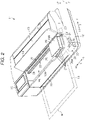
FIG. 2 is a perspective view showing the state in which a maintenance cover of the liquid discharge device is opened. -
FIG. 3 is a schematic cross-sectional side view of the liquid discharge device broken along the line 3-3 inFIG. 1 . -
FIG. 4 is a plan view showing the inside of the liquid discharge device when a carriage is located at a home position. -
FIG. 5 is a plan view showing the inside of the liquid discharge device when the carriage is located at a first position where cartridge replacement is performed. -
FIG. 6 is a schematic front view when the carriage is located at the home position. -
FIG. 7 is a schematic front view when the carriage is located at the first position. - FIG. 8A is a schematic front view when mounting a liquid cartridge.
-
FIG. 9 is a schematic bottom view showing a nozzle surface of a discharge head. -
FIG. 10 is a schematic front view showing a wiping operation to the discharge head. -
FIG. 11 is a schematic front view showing a position of the discharge head when the wiping operation is completed. -
FIG. 12 is a schematic plan view showing the discharge head and a medium when printing is stopped due to liquid end. -
FIG. 13 is a schematic plan view showing an evacuation operation of the medium. -
FIG. 14 is a schematic plan view showing a restoration position of the medium when resuming the printing. -
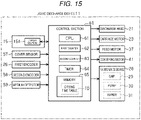
FIG. 15 is a block diagram showing an electrical configuration of the liquid discharge device. -
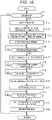
FIG. 16 is a flowchart showing cartridge replacement control. - Embodiments of the liquid discharge device hereinafter are described with reference to the drawings. The liquid discharge device according to the present embodiment is an inkjet-type printer for jetting ink as an example of the liquid to a medium such as a form to print characters, an image or the like on the medium.
- In
FIG. 1 , a vertical direction is represented by a Z axis, and directions parallel to a horizontal plane are defined as an X-axis direction and a Y-axis direction assuming that theliquid discharge device 11 is installed on the horizontal plane. In other words, the X-axis direction corresponding to the width direction, the Y-axis direction corresponding to the depth direction and the Z-axis direction corresponding to the vertical direction when viewing theliquid discharge device 11 from the front are directions different from each other, and are perpendicular to each other. In the depth direction, one end side is referred to as a front surface side or a front side, and the other end side opposite to the one end side is referred to as a back surface side or a rear side in some cases. It should be noted that the X-axis direction corresponds to an example of a first axis direction, and the Y-axis direction corresponds to an example of a second axis direction. - As shown in
FIG. 1 , theliquid discharge device 11 is provided with ahousing 12 having a substantially rectangular solid shape. On an upper surface of thehousing 12, there are disposed apaper feed cover 13 located on the rear side and amaintenance cover 14 located on the front side so as to be able to be opened and closed. At a position adjacent in the X-axis direction to themaintenance cover 14 in the upper surface of thehousing 12, there is disposed anoperation panel 15 for performing a variety of operations of theliquid discharge device 11. - As shown in
FIG. 1 , inside thehousing 12, there is disposed acarriage 20 so as to be able to be translated in the X-axis direction. On thecarriage 20, there is mounted adischarge head 21 capable of discharging a liquid such as ink to a medium M conveyed. Thedischarge head 21 is fixed to a bottom part of thecarriage 20 so as to be able to be opposed to the medium M conveyed. By discharging the liquid from thedischarge head 21 toward the medium M while thecarriage 20 is reciprocating in the X-axis direction, an image or a document is printed in a printed area IA as an area on which droplets are discharge in the medium M. Theliquid discharge device 11 is provided with anoutlet 16 in a front surface thehousing 12. The medium M having been printed with the image and so on formed by thedischarge head 21 discharging the liquid inside thehousing 12 is ejected from theoutlet 16. In the present embodiment, the X-axis direction coincides with a scanning axis as a moving direction of thecarriage 20. - As shown in
FIG. 2 , themaintenance cover 14 can be opened and closed around the rear end part as an axis. When opening themaintenance cover 14, thecarriage 20 and a moving area MA of thecarriage 20 are exposed from an opening 12A disposed in the upper surface of thehousing 12. Further, a part of amoving mechanism 22 for moving thecarriage 20 in the X-axis direction is also exposed from the opening 12A. Themoving mechanism 22 is constituted by acarriage motor 23, a pair ofpulleys 24, atiming belt 25 and so on, wherein thecarriage motor 23 is a power source of thecarriage 20, thetiming belt 25 is wound around the pair ofpulleys 24, and a part of thetiming belt 25 is fixed to thecarriage 20. By thecarriage motor 23 being driven in forward and reverse directions, thecarriage 20 reciprocates in the X-axis direction in the moving area MA, and the liquid is discharged from thedischarge head 21 in the moving process to thereby print the medium M. Further, afirst encoder 26 formed of a linear encoder is disposed so as to extend along the moving path of thecarriage 20. Speed control and position control of thecarriage 20 are performed based on a pulse signal output from thefirst encoder 26. - On the
carriage 20, there is detachably mounted aliquid cartridge 27 as an example of the liquid container in which the liquid such as ink to be supplied to thedischarge head 21 is contained. Thecarriage 20 has the plurality ofliquid cartridges 27 and thedischarge head 21 mounted thereon, and moves in the X-axis direction. Theliquid cartridges 27 are mounted at an upper position of thedischarge head 21 in thecarriage 20. Thecarriage 20 has amain body 20A and acover 20B wherein themain body 20A is capable of housing the plurality ofliquid cartridges 27, and thecover 20B covers the plurality ofliquid cartridges 27 housed in themain body 20A from above. There is mounted the plurality ofliquid cartridges 27 containing a plurality of colors of ink including, for example, cyan, magenta, yellow and black, respectively. It is also possible to adopt a configuration in which there is mounted a singleliquid cartridge 27 for a single color of, for example, black. It should be noted that the liquid container is not limited to theliquid cartridge 27, but can also be a tank or an adapter which is mounted on thecarriage 20, and in which the liquid is contained. - When printing is not performed, the
carriage 20 waits at a home position HP shown inFIG. 2 . Below thecarriage 20 located at the home position HP, there is disposed amaintenance device 28 for performing maintenance on thedischarge head 21. Themaintenance device 28 is provided with acap 29, apump 30, awiper 31 shown inFIG. 6 and so on. Thecap 29 is disposed outside the range in which thedischarge head 21 moves while discharging the liquid on the medium M when thedischarge head 21 moves in the X-axis direction together with thecarriage 20 in the moving area MA of thecarriage 20. In other words, in the X-axis direction, with respect to the range in which thedischarge head 21 moves while discharging the liquid on the medium M, thecap 29 is disposed outside the boundary of that range. When thecarriage 20 waits at the home position HP, thedischarge head 21 is capped with thecap 29 having contact with thedischarge head 21. Due to the capping, the ink inside a nozzle of thedischarge head 21 is prevented from increasing in viscosity or drying. - As shown in
FIG. 3 , theliquid discharge device 11 is provided with aguide shaft 32 extending in the X-axis direction inside thehousing 12. Theguide shaft 32 is bridged in the state of being supported by aframe 18 at a predetermined height position in the Z-axis direction inside thehousing 12. In the present embodiment, there is provided arail section 33 extending in the X-axis direction at a height position above theguide shaft 32. Therail section 33 is formed by performing a bending work on a part of theframe 18, and functions as a support shaft together with theguide shaft 32. Thecarriage 20 is arranged to be able to move in the X-axis direction as an extending direction of theguide shaft 32 while being guided by theguide shaft 32 and therail section 33. Thedischarge head 21 is supported by thecarriage 20, and reciprocates in the X-axis direction together with thecarriage 20. Thedischarge head 21 has anozzle surface 21A on which nozzles N open. Nozzles N is for discharging the liquid such as the ink. It should be noted that although four nozzles N are schematically illustrated inFIG. 3 , a predetermined number of nozzles N in a range of 100 through 500 are disposed in, for example, the Y-axis direction. - Further, the
liquid discharge device 11 is provided with the movingmechanism 22 for moving thecarriage 20. The movingmechanism 22 is constituted by thecarriage motor 23, thetiming belt 25 and so on besides theguide shaft 32 and therail section 33 for supporting thecarriage 20, wherein thecarriage motor 23 is the power source of thecarriage 20, and thetiming belt 25 is wound around thepulleys 24 rotating the power of thecarriage motor 23. Thecarriage 20 is fixed to a part of thetiming belt 25, and is reciprocated in the X-axis direction by thecarriage motor 23 being driven in the forward and reverse directions. Further, theliquid discharge device 11 is provided with thefirst encoder 26 for detecting a moving position in the X-axis direction of thecarriage 20. - The
liquid discharge device 11 is provided with afeed section 35 for feeding the medium M. Thefeed section 35 is provided with afeed shaft 36 which can install a roll body R obtained by rolling medium M in a layered manner to form a cylindrical shape, and can rotate. Afeed motor 37 shown inFIG. 13 as a power source of thefeed shaft 36 is driven, and thus the roll body R rotates in the counterclockwise direction inFIG. 3 together with thefeed shaft 36 to thereby feed the medium M. The medium M fed from the roll body R is, for example, a continuous form. Further, thefeed section 35 is capable of supplying the medium M formed of, for example, a cut form via apaper inlet 17 as indicated by a dashed-two dotted line inFIG. 2 . - Further, as shown in
FIG. 3 , theliquid discharge device 11 is provided with aguide member 38 for guiding the medium M fed from thefeed section 35, and a conveyingsection 40 for conveying the medium M guided by theguide member 38. The conveyingsection 40 conveys the medium M in at least the Y-axis direction as an example of the second axis direction as a direction crossing the X-axis direction. The conveyingsection 40 uses a conveyingmotor 41 shown inFIG. 13 as a power source. Further, theliquid discharge device 11 is provided with asupport stage 42 for supporting the medium M conveyed by the conveyingsection 40. An upper surface of thesupport stage 42 forms a mountingsurface 42A on which the medium M is mounted. The conveyingsection 40 conveys the medium M in a direction crossing the X-axis direction of thedischarge head 21. It should be noted that in the present embodiment, the X-axis direction coincides with the width direction of the medium M conveyed in the Y-axis direction. - The conveying
section 40 is provided with a conveyingroller pair 43, arelay roller pair 44 and anejection roller pair 45, wherein the conveyingroller pair 43 is located on the upstream of thedischarge head 21, therelay roller pair 44 is located on the downstream of thedischarge head 21, and theejection roller pair 45 is located on the downstream of therelay roller pair 44 in the conveying path on which the medium M is conveyed. The conveyingroller pair 43 rotates in the state of pinching the medium M to thereby convey the medium M toward thesupport stage 42. Therelay roller pair 44 is disposed on the downstream of thesupport stage 42, and feeds the medium M toward theejection roller pair 45. Between the conveyingroller pair 43 and theejection roller pair 45 in the conveying path, the medium M is conveyed in a direction of an axis included in a plane the normal direction of which coincides with the discharge direction of an ink droplet discharged from thedischarge head 21. In the present embodiment, the discharge direction of the ink droplet is the Z-axis direction, and the conveying direction of the medium M is perpendicular to the X-axis direction, and therefore, the conveying direction of the medium M between the conveyingroller pair 43 and theejection roller pair 45 in the conveying path is parallel to the Y-axis direction. - The
discharge head 21 discharges the liquid to a part supported by thesupport stage 42 in the medium M to thereby print the image and so on. Thedischarge head 21 is mounted on thecarriage 20 in the posture in which thenozzle surface 21A on which the nozzles N open is opposed to the mountingsurface 42A of thesupport stage 42. Thedischarge head 21 is an inkjet head for performing a print processing of performing printing by discharging the liquid such as the ink on the medium M mounted on the mountingsurface 42A while moving in the X-axis direction together with thecarriage 20. Theliquid discharge device 11 makes the ink droplets discharged by thedischarge head 21 adhere to the medium M to thereby print an image formed of a dot group. - Further, the
liquid discharge device 11 is provided with acutting section 46 capable of cutting the medium M on which recording has been performed by thedischarge head 21. The cuttingsection 46 has a pair ofrotary blades 46A which can rotate. The pair ofrotary blades 46A are disposed at a position where the medium M can be pinched from above and below. The cuttingsection 46 cuts the medium M supplied from the roll body R and having been printed into a desired length by moving in the X-axis direction while pinching the medium M from above and below and cutting the medium M with therotary blades 46A. Due to thecutting section 46, the medium M having been printed is cut at the cutting position between parts nipped by therelay roller pair 44 and theejection roller pair 45. When the medium M is the cut form supplied from thepaper inlet 17, the cuttingsection 46 is not driven. Theejection roller pair 45 rotates in the state of pinching the medium M to thereby eject the medium M from theoutlet 16. Thedischarge head 21, theguide member 38, the conveyingsection 40, thesupport stage 42 and thecutting section 46 are housed in thehousing 12. Further, inside thehousing 12, there is disposed acontrol section 60 for controlling theliquid discharge device 11. - As shown in
FIG. 4 , thecarriage 20 waits at the home position HP shown inFIG. 4 and set in one end part in the X-axis direction in a scanning range of thecarriage 20 when printing is not performed. Thecarriage 20 can move in a range of the moving area MA from the home position indicated by the solid lines inFIG. 4 to an anti-home position indicated by the dashed-two dotted lines inFIG. 4 . In thehousing 12, there is disposed thesupport stage 42 at a position corresponding to an area below the moving path of thecarriage 20. Due to the rotational drive of thefeed shaft 36 by thefeed motor 37, thefeed section 35 feeds the medium M from the roll body R installed in thefeed shaft 36 toward the downstream in the conveying path. The roll body R is pressed at a plurality of places by a plurality of pressingrollers 39 disposed along the X-axis direction from above the outer circumferential surface of the roll body R. Further, at positions between thefeed section 35 and thesupport stage 42 in the conveying path, there is disposed a plurality ofpressing rollers 40A constituting a part of the conveyingsection 40. The medium M having been fed from the roll body R is supplied to an area above the mountingsurface 42A of thesupport stage 42 by the conveyingsection 40 driven by the power of the conveyingmotor 41 while being guided by therollers carriage 20 reciprocates in the X-axis direction within a range of a print processing area PA in which thedischarge head 21 can discharge the liquid by thecarriage motor 23 driving when printing is performed. The print processing area PA is included in the moving area MA which is an area between the home position HP and the anti-home position AP. When thecarriage 20 is located at the home position HP, thedischarge head 21 is located outside the conveying area FA and the print processing area PA in the X-axis direction. - Here, the conveying area FA denotes the area of the maximum range in which the medium M is conveyed, and corresponds to an area in which the medium M having the maximum width is conveyed. Further, the print processing area PA is a print range in which printing is performed on the medium M having the maximum width, and corresponds to the print range when performing margin-less printing on the medium M having the maximum width. It should be noted that the conveying area FA and the print processing area PA are substantially the same in size in the X-axis direction in the present embodiment, but in a model compatible with protrusion printing, the print processing area PA is slightly longer than the conveying area FA as much as an amount corresponding to the protrusion amount in a precise sense.
-
FIG. 5 shows the state in which thecarriage 20 is disposed at the first position P1 when replacing theliquid cartridge 27. In the present embodiment, the first position P1 is set to a position where thenozzle surface 21A is located at a side end at the home position HP side of the conveying area FA of the medium M, namely located between a side end M1 on the home position HP side of the medium M having the maximum width conveyed and the home position HP, when thecarriage 20 is located at the first position P1. The first position P1 can also be a position between a side end at the home position HP side of the print processing area PA, namely a side end at the home position HP side of the print processing area PA as an area where the margin-less printing is performed on the medium M having the maximum width conveyed, and the home position HP. - As shown in
FIG. 6 , at a lower position opposed to thecarriage 20 located at the home position HP, there is disposed themaintenance device 28. Themaintenance device 28 is provided with thecap 29 at the position opposed to thedischarge head 21 disposed at the home position HP. Thecap 29 can move up and down, and moves in a vertical direction Z between an evacuation position shown inFIG. 7 and a capping position shown inFIG. 6 . When thecarriage 20 waits at the home position HP, thecap 29 moves up to have contact with thenozzle surface 21A to cap thedischarge head 21. - Further, the
maintenance device 28 is provided with thepump 30 and thewiper 31. Thewiper 31 is located on the print processing area PA side of thecap 29. Thepump 30 is, for example, a suction pump, and is driven in the state in which thecap 29 shown inFIG. 6 has contact with thenozzle surface 21A to cap thedischarge head 21 to thereby eject the air in thecap 29. Themaintenance device 28 provides the closed space surrounded by thenozzle surface 21A and the cap with negative pressure to thereby perform suction cleaning for forcibly performing the suction ejection of the liquid from the nozzles N. Cleaning is not limited to the suction cleaning, but can also be pressure cleaning for forcibly ejecting the liquid from the nozzles N by pressurizing the liquid of the liquid supply source such as theliquid cartridge 27 or the like with a pressurizing pump from the upstream of the liquid flow channel in thedischarge head 21. The cleaning is performed periodically or irregularly, and in addition, when replacing theliquid cartridge 27. This is because bubbles are mixed in the liquid flow channel on thecarriage 20 side in some cases when replacing theliquid cartridge 27. Further, since theliquid cartridge 27 is pushed into thecarriage 20 when mounting theliquid cartridge 27 to be replaced with, when thecarriage 20 deforms due to the pushing force on that occasion, and thus the liquid flow channel is pressurized, the liquid is leaked from the nozzles N in some cases. The liquid leaked from the nozzles N adheres to thenozzle surface 21A, or drops as a droplet. The liquid having adhered to thenozzle surface 21A has contact with the droplet discharged from the nozzle N to become a cause of the flight deflection of the droplet. Therefore, after replacing theliquid cartridge 27, there are performed the cleaning and wiping for wiping thenozzle surface 21A with thewiper 31. - The
wiper 31 provided to themaintenance device 28 is configured to be able to move up and down independently of thecap 29. Thewiper 31 is arranged to be able to move in the vertical direction Z to the evacuation position shown inFIG. 6 and FIG. 7 , and the wiping position shown inFIG. 11 . As shown inFIG. 10 , thewiper 31 wipes thenozzle surface 21A when thecarriage 20 moves on one side (the +X direction) in the X-axis direction in the state in which thewiper 31 is disposed at the wiping position. -
FIG. 7 shows the state in which thecarriage 20 is disposed at the first position P1 where the cartridge replacement is performed. As shown inFIG. 7 and according to the invention, the first position P1 is set to the position of thecarriage 20 where thewhole nozzle surface 21A is opposed to an area PCA between the side end M1 on thecap 29 side in the conveying area FA of the medium M and a side end C1 on the conveying area FA side in thecap 29 in the X-axis direction. In other words, the first position P1 is set to the position of thecarriage 20 where thenozzle surface 21A is opposed to the area PCA between the conveying area FA and thecap 29. Further, the first position P1 of the present embodiment is also the position of thecarriage 20 where thenozzle surface 21A is opposed to the area PCA between the print processing area PA and thecap 29. When thecarriage 20 is placed at the first position P1, thenozzle surface 21A does not overlap the medium M in the vertical direction Z irrespective of the size of the medium M. Further, when thecarriage 20 is placed at the first position P1, thenozzle surface 21A does not overlap thecap 29 in the vertical direction Z. - Further, as shown in
FIG. 10 and FIG. 11 , thecap 29 is provided with ahead guide member 55 throughout an upper side and the periphery of thecap 29. Thehead guide member 55 can move up and down together with thecap 29, and induces thedischarge head 21 to thecap 29 in the process of moving upward. In the configuration having thehead guide member 55, it is preferable for the first position P1 to be set to the position of thecarriage 20 where thenozzle surface 21A is opposed to an area between the side end M1 of the conveying area FA and a side end C2 on the conveying area FA side of thehead guide member 55 in the X-axis direction. - According to the invention, it is required for the first position P1 where the
liquid cartridge 27 is replaced that thewhole nozzle surface 21A is shifted outside at least the conveying area FA of the medium M toward thecap 29. Further, it is also possible for thenozzle surface 21A to be shifted outside the print processing area PA toward thecap 29 side. According to the invention, is required for thenozzle surface 21A to be shifted outside thecap 29. According to a comparative example, not according to the invention, this is not preferable since the device size in the X-axis direction of theliquid discharge device 11 increases. According to the comparative example, when thedischarge head 21 is located at a position where thedischarge head 21 overlaps thecap 29, thedischarge head 21 has contact with thecap 29 to apply a load to thecap 29 when thedischarge head 21 is displaced downward due to the pushing force when replacing the cartridge, which is to be avoided according to the invention. Therefore, according to the invention, the first position P1 is a position of thecarriage 20 where thenozzle surface 21A is opposed to the area PCA which is an area outside the side end M1 on thecap 29 side of the medium M having the maximum width, namely an area outside the conveying area FA, and which does not overlap thecap 29 and located inner side of thecap 29. Therefore, according to the invention, the first position P1 is a position which fulfills the condition that the whole of thenozzle surface 21A fits into the area PCA between the side end M1 on the cap side in the conveying area FA of the medium M and the side end C1 on the conveying area FA side of thecap 29 in the X-axis direction. - As shown in
FIG. 7 , the bottom surface of thecarriage 20 resting at the first position P1 is opposed to abottom frame 19. Theliquid discharge device 11 hasfirst projections 51 as an example of a projection capable of having contact with acarriage surface 20C when thenozzle surface 21A is located at the first position P1. Thecarriage surface 20C is a surface, of thecarriage 20, on the side in the direction (-Z direction) in which the liquid is discharged. In the other words, thecarriage surface 20C is a surface configured to face to the medium M conveyed. Thefirst projections 51 project from an upper surface of thebottom frame 19 upward in the vertical direction Z. When thecarriage surface 20C of thecarriage 20 and theprojections 51 have contact with each other, thenozzle surface 21A and the upper surface of thebottom frame 19 located at the position opposed to thenozzle surface 21A are separated from each other. In the present embodiment, in a part of the bottom surface of thecarriage 20 other than thedischarge head 21, there are formedsecond projections 52 projecting downward at positions opposed to thefirst projections 51 in the state in which thecarriage 20 stops at the first position P1. As shown inFIG. 9 , thesecond projections 52 are disposed on the bottom surface of thecarriage 20 at positions on both sides across thedischarge head 21 in the Y-axis direction from each other as a pair of projections. - As shown in
FIG. 8 , when theliquid cartridge 27 which is new or to which the liquid has been injected is pushed in thecarriage 20 by the user when mounting theliquid cartridge 27 on thecarriage 20 for replacing the liquid cartridge, a component made of synthetic resin such as thecarriage 20 deforms for a moment due to the pushing force. On this occasion, thenozzle surface 21A of thedischarge head 21 moves down for a moment, but thefirst projections 51 and thecarriage surface 20C have contact with each other to prevent thenozzle surface 21A from further moving downward. In the present embodiment, thefirst projections 51 and thesecond projections 52 have contact with each other to prevent thenozzle surface 21A from further moving downward. As a result, a gap GH is kept between thenozzle surface 21A and thebottom frame 19, and thus, thenozzle surface 21A and thebottom frame 19 are prevented from having contact with each other. In the present embodiment, since thesecond projections 52 are formed on thecarriage 20 side, as shown inFIG. 8 , a lower end surface of each of thesecond projections 52 forms thecarriage surface 20C. By forming thesecond projections 52 on thecarriage 20 side, it is possible to suppress the projection height of thefirst projections 51 on thebottom frame 19 side to a low level. It should be noted that it is also possible to adopt a configuration in which thesecond projections 52 are eliminated, and thefirst projections 51 has direct contact with the carriage surface formed of the bottom surface of thecarriage 20. - As shown in
FIG. 9 , on thenozzle surface 21A of thedischarge head 21, there are disposed the same number of nozzle columns NR as the number of theliquid cartridges 27 to be mounted on thecarriage 20. The nozzle columns NR are each formed of a group of M nozzles N arranged at a predetermined nozzle pitch in the Y-axis direction. It should be noted that M is a predetermined value within a range of, for example, 100 through 500. Here, the size in the Y-axis direction of the range in which the plurality of nozzles N constituting the nozzle column NR is defined as a nozzle column dimension NL, and the size in the Y-axis direction of thenozzle surface 21A is defined as a nozzle surface dimension PL. - As shown in
FIG. 10 , thenozzle surface 21A is wiped by thewiper 31 disposed at the wiping position in the process in which thecarriage 20 moves from the home position HP toward the conveying area FA. On this occasion, thewiper 31 made of an elastic material such as elastomer or rubber wipes thenozzle surface 21A in the state of having contact with thenozzle surface 21A and thus curved as shown inFIG. 10 . There is a possibility that the liquid scraped by thewiper 31 flies on the periphery, and the periphery and the medium M are made dirty when thewiper 31 instantaneously stretches from the state of being curved to restore to the original state when wiping has been completed and then thewiper 31 disengages from thenozzle surface 21A. Therefore, in order to gently restore thewiper 31 from the state of being curved during the wiping to the state of being stretched, thecarriage 20 is provided with aslope 53 at an adjacent position on the downstream in the wiping direction of thewiper 31 in thedischarge head 21. Theslope 53 is tilted in a direction in which the position in the vertical direction Z gradually rises as the distance from thenozzle surface 21A increases. - Here, in order only to simply wipe the
nozzle surface 21A, it is sufficient to move thecarriage 20 to the print processing area PA side of thewiper 31 as much as the width dimension of thenozzle surface 21A when performing wiping. However, when thecarriage 20 having theslope 53 is used, it is necessary to move thecarriage 20 excessively as much as extra length corresponding to the dimension in the X-axis direction of theslope 53 toward the print processing area PA. In the case of the present embodiment, when thecarriage 20 is moved toward the print processing area PA to the position necessary for the wiping, it results in that thecarriage 20 is moved to the position where thenozzle surface 21A is opposed to the medium M as shown inFIG. 11 . - As shown in
FIG. 11 , in order to use theslope 53 when performing the wiping with thewiper 31, it is necessary to ensure the wiping stroke no smaller than the dimension obtained by adding the slope dimension WL as the dimension in the X-axis direction of theslope 53 to the head width HL as the dimension in the X-axis direction of thedischarge head 21. When thewiper 31 performs the wiping operation with the wiping stroke, there is achieved the positional relationship in which thedischarge head 21 and the medium M are opposed to each other in the vertical direction Z when thedischarge head 21 has moved to the wiping completion position. In other words, a part on the side end M1 side of the medium M is opposed in the vertical direction Z to thenozzle surface 21A. - On this occasion, when the printed area IA on which the liquid discharged from the
discharge head 21 adheres in the medium M swells with the liquid and bulges, there is a concern that thenozzle surface 21A scrapes against the printed area IA on the medium M in the process in which thedischarge head 21 moves to the wiping completion position shown inFIG. 11 . Further, as shown inFIG. 12 , when the printed area IA of the medium M is located in a nozzle surface opposed area HA opposed to thenozzle surface 21A, there is a concern that thenozzle surface 21A having moved to the wiping completion position has contact with a bulging part of the medium M due to cockling which is a phenomenon that the medium M having absorbed the ink swells and thus waves when performing wiping. When thenozzle surface 21A has contact with the printed area IA of the medium M, there is a concern that thenozzle surface 21A scrapes against the print surface to degrade the print quality, or there occurs a discharge failure that the liquid meniscus having just been adjusted of the nozzles N of thenozzle surface 21A immediately after cleaning is broken to make it unachievable to appropriately discharge the droplet. - Therefore, in the present embodiment, when replacing the cartridge, it is arranged that the medium M is evacuated along the Y-axis direction to a position where the
discharge head 21 in the process of wiping and the printed area IA are not opposed to each other. In the other words, thecontrol section 60 evacuates the printed area IA from the nozzle surface opposed area HA. Therefore, in the present embodiment, even thenozzle surface 21A is supposedly opposed to the medium M when performing wiping after cleaning, thenozzle surface 21A is opposed to the medium M in a part other than the printed area IA, the printed area IA being apt to bulge due to the cockling or the like, and thenozzle surface 21A is therefore prevented from having contact with the medium M. -
FIG. 12 through FIG. 14 describe the operation performed when replacing the cartridge. When liquid end occurs, printing is aborted, and printing is stopped in the state shown in, for example,FIG. 12 . On this occasion, a part of the printed area IA is located in the nozzle surface opposed area HA which can be opposed to thenozzle surface 21A of thedischarge head 21. When the part of the printed area IA of the medium M is located in the nozzle surface opposed area HA, when the medium M bulges in the printed area IA part due to cockling or the like, there is a concern that thenozzle surface 21A and the printed area IA scrape against each other when thedischarge head 21 moves to the wiping completion position. - Therefore, in the present embodiment, the printed area IA is evacuated in the Y-axis direction from the nozzle surface opposed area HA. In the present embodiment, the
control section 60 moves the printed area IA attached with the ink to the downstream of the nozzle surface opposed area HA in the conveying path in the evacuation operation. In other words, due to the evacuation operation, the printed area IA attached with the ink moves to the +Y side in the Y-axis direction. On this occasion, the direction toward the +Y side corresponds to the direction toward an opposite side to the -Y side, where an area which has not yet been attached with the ink out of the medium M is located, from the nozzle surface opposed area HA. In other words, the printed area IA is moved to the opposite side to the area on which the liquid has not yet been discharged about the nozzle surface opposed area HA. It should be noted that it is also possible to evacuate the printed area IA toward the upstream in the conveying path, namely toward the -Y side providing the printed area IA is located within the range up to the position anterior to a part to be wound by the roll body R. When the printed area IA moves to the +Y side of the nozzle surface opposed area HA, the area which has not yet been attached with the ink out of the medium M is located in the nozzle surface opposed area HA. The area which has not yet been attached with the ink out of the medium M is hard to bulge compared to the area attached with the ink. Therefore, the possibility that thenozzle surface 21A and the printed area IA scrape against each other when thedischarge head 21 has moved to the wiping completion position is further reduced. - When the replacement of the
liquid cartridge 27 has been instructed, namely when the replacement of theliquid cartridge 27 is performed, thecontrol section 60 performs the evacuation operation of conveying the medium M to evacuate the printed area IA attached with the ink discharged by thedischarge head 21 out of the medium M. There is performed the evacuation operation of moving the medium M toward the downstream in the conveying path to evacuate the printed area IA on the medium M toward the +Y side from the nozzle surface opposed area HA opposed to thenozzle surface 21A. Here, in the evacuation operation, the conveying length of the medium M in the Y-axis direction is larger than the nozzle surface dimension PL (seeFIG. 9 ) as the dimension in the Y-axis direction of thenozzle surface 21A. As a result, as shown inFIG. 13 , the printed area IA of the medium M is evacuated to the outside of the nozzle surface opposed area HA in the Y-axis direction. - In particular in the present embodiment, as shown in
FIG. 13 , thecontrol section 60 locates the printed area IA on which the liquid has been discharged outside thehousing 12 from theoutlet 16 in the evacuation operation. The conveying length FL (seeFIG. 13 ) of the medium M conveyed in the evacuation operation is set to the value with which the whole of the printed area IA can be evacuated on the downstream in the conveying path of theoutlet 16, namely outside thehousing 12. Therefore, the printed area IA is ejected outside thehousing 12 by the evacuation operation. Here, since the liquid such as the ink is discharged inside thehousing 12, the inside of thehousing 12 is higher in humidity compared to the outside of thehousing 12. Therefore, by evacuating the printed area IA to the outside of thehousing 12, drying of the ink in the printed area IA is facilitated compared to the case in which the printed area IA is located inside thehousing 12. - The
control section 60 evacuates the whole of the printed area IA to the outside of the nozzle surface opposed area HA in the present embodiment, but it is also possible to adopt a configuration in which thecontrol section 60 evacuates at least an area on which the liquid has just been discharged out of the printed area IA to the outside of the nozzle surface opposed area HA. The "area on which the liquid has just been discharged" is an area located in the nozzle surface opposed area HA at the time point when printing is aborted shown in, for example,FIG. 12 . The medium M is the easiest to swell immediately after the liquid is discharged, and has a high possibility of bulging. Therefore, according to this configuration, the possibility that thenozzle surface 21A and the medium M have contact with each other is reduced while suppressing the moving amount of the medium M compared to the configuration of evacuating the whole of the printed area IA to the outside of the nozzle surface opposed area HA. - Further, it is also possible to adopt a configuration in which the
control section 60 moves the medium M toward the upstream in the conveying path instead of moving the medium M toward the downstream in the conveying path to thereby evacuate the whole of the printed area IA or at least the area on which the liquid has just been discharged outside the nozzle surface opposed area HA. According to this configuration, by ejecting the printed area IA, which should not be ejected outside thehousing 12 from theoutlet 16 in the normal printing, outside thehousing 12, the possibility that the print quality is degraded due to some external factor is reduced. - Further, as shown in
FIG. 14 , when completion of the replacement of theliquid cartridge 27 has been detected after the evacuation operation of the medium M, the medium M is moved toward the upstream in the conveying path. In other words, the medium M is conveyed in the direction toward the -Y side opposite to the direction toward the +Y side which is the conveying direction of the medium M in the evacuation operation. Thecontrol section 60 conveys the medium M toward the -Y side as much as the conveying length corresponding to the conveying length FL of the conveyance of the medium M toward the +Y side in the evacuation operation in the Y-axis direction. As a result, the medium M is returned to the original conveyance position when the printing is aborted due to the liquid end. Thecontrol section 60 conveys the medium M in the direction toward the -Y side to return the medium M to the original conveyance position, then moves thecarriage 20 from the first position P1 toward the print processing area PA and then discharges the ink from the nozzles N of thedischarge head 21 on the medium M for resuming the printing. - In the present embodiment, as one of the operation related to the replacement of the
liquid cartridge 27 by the user, there are performed the evacuation operation of evacuating the medium M to the outside of the nozzle surface opposed area HA, and the operation of returning the medium M to the original conveyance position when aborting the printing, but this is not a limitation. For example, when aborting the printing for a predetermined period due to the instruction of the user or the like, and then resuming the printing, it is possible to perform the operation of evacuating the medium M to the outside of the nozzle surface opposed area HA, and the operation of returning the medium M to the original conveyance position when aborting the printing. - The printing resumption position of the medium M is set in an area partially overlapping the printed area IA before the medium M evacuates, or set in an area adjacent to the upstream of the printed area IA. Therefore, printing after the replacement of the liquid cartridge is resumed from the area partially overlappingthe printed area IA, or the area adjacent to the upstream of the printed area IA. It should be noted that in the former case, the dimension ΔL (
FIG. 14 ) of a part overlapping in the Y-axis direction is preferably a value within a range of 1 through 3 dots in the unit of dot formed by discharging the liquid from the nozzle N. Thus, the areas IA printed before and after the abort of the printing are made to partially overlap each other to thereby make banding (stripe) and so on inconspicuous. It should be noted that the dimension ΔL is a dimension in the Y-axis direction of a part where a nozzle opposed area NA opposed to one column of nozzles N in the X-axis direction and the printed area IA overlap each other. - Then, an electrical configuration of the
liquid discharge device 11 will be described with reference toFIG. 15 . As shown inFIG. 15 , theliquid discharge device 11 prints an image based on print data received from a host device not shown on the medium M. Theliquid discharge device 11 is provided with thecontrol section 60 responsible for a variety of types of control including the moving control of thecarriage 20. To thecontrol section 60, there are electrically connected thedischarge head 21, thecarriage motor 23, thefeed motor 37 and the conveyingmotor 41. Further, to thecontrol section 60, there are connected theoperation panel 15, acover sensor 57, thefirst encoder 26, asecond encoder 58 and amedium detector 59. Theoperation panel 15 is provided with a display section 15A. - The
control section 60 controls thedischarge head 21 based on the print data to thereby discharge an ink droplet from the nozzles N. Further, thecontrol section 60 controls thecarriage motor 23 to thereby perform the position control and the speed control of thecarriage 20. When thecontrol section 60 performs the forward drive of thecarriage motor 23, thecarriage 20 moves forward in the +X direction of getting away from the home position HP, and when thecontrol section 60 performs the reverse drive of thecarriage motor 23, thecarriage 20 moves backward in the -X direction of getting closer to the home position HP. Further, thecontrol section 60 controls thefeed motor 37 to thereby drive thefeed section 35, and thus feeds the medium M formed of a cut form via thepaper inlet 17, or unwinds the roll body R to feed the medium M formed of the continuous medium. Further, thecontrol section 60 controls the conveyingmotor 41 to thereby drive the conveyingsection 40, and thus conveys the medium M thus fed in the Y-axis direction due to the drive of the roller pairs 43 through 45. - The
control section 60 displays a menu and a variety of messages on the display section 15A of theoperation panel 15. Thecontrol section 60 manages the remaining amount of the liquid in theliquid cartridge 27, and informs the user of the fact that the remaining amount of the liquid reaches the liquid end by displaying the message representing the liquid end on the display section 15A when the remaining amount of the liquid has reached the liquid end. - The
carriage 20 has terminals not shown on the mounting surface of theliquid cartridge 27. Theliquid cartridge 27 has a storage element mounted thereon, and has terminals on a mounting target surface. When removing theliquid cartridge 27 from thecarriage 20, the terminals on the both surfaces are separated from each other to get into an electrically non-contact state, and in contrast, when mounting theliquid cartridge 27 on thecarriage 20, the terminals on the both surfaces are electrically connected. Thecontrol section 60 detects mounting and removal of theliquid cartridge 27 through the connection and disconnection between the terminals of theliquid cartridge 27 and the terminals of thecarriage 20. Further, thecontrol section 60 is capable of reading and writing the storage element via the connection between the terminals on the both sides in the state in which theliquid cartridge 27 is mounted on thecarriage 20. The storage element of theliquid cartridge 27 stores liquid related information such as part number information, liquid color information, and liquid remaining-amount information. Thecontrol section 60 manages consumption of the liquid consumed in printing and so on by theliquid discharge device 11, and manages the current remaining amount of the liquid by subtracting the consumption of the liquid from the remaining-amount information retrieved from the storage element. The remaining amount of the liquid is retrieved from the storage element when powering on theliquid discharge device 11, and when powering off theliquid discharge device 11, the information of the remaining amount of the liquid having been measured up to that time is written to the storage element. - The
control section 60 periodically determines whether or not the remaining amount of the liquid has reached the liquid end, and gives information of that fact when the liquid end has been reached. Further, when the user opens themaintenance cover 14 in the state in which a liquid end flag is set in amemory 65 after thecontrol section 60 has detected the liquid end and gives the information of the liquid end, thecontrol section 60 regards input of the detection signal from thecover sensor 57 which has detected the open of themaintenance cover 14 as issuance of the instruction of the replacement of theliquid cartridge 27. - The
control section 60 is provided with aCPU 61 as a processor, afirst counter 62, asecond counter 63, atimer 64 and thememory 65. Thememory 65 stores a variety of programs to be executed by theCPU 61. The programs include a program for controlling the cartridge replacement expressed by the flowchart inFIG. 16 . TheCPU 61 executes the program for controlling printing stored in thememory 65 to thereby perform a variety of types of printing control. Further, theCPU 61 executes the program expressed by the flowchart inFIG. 16 to thereby perform the control when replacing the cartridge. Here, the control when replacing the cartridge is the control for helping the replacement of theliquid cartridge 27 by the user, and at the same time suppressing degradation of the print quality due to the abort of printing when the cartridge replacement is performed in the process of the printing. The control when replacing the cartridge includes moving thecarriage 20 to the first position P1 where the cartridge replacement is performed, the evacuation operation of the medium M, and so on. - The
first counter 62 counts the number of pulse edges of the pulse signal from thefirst encoder 26 using the home position HP of thecarriage 20 as an origin to thereby obtain a count value representing the carriage position in accordance with the instruction of theCPU 61. In detail, thecontrol section 60 compares two phases included in the pulse signal from thefirst encoder 26 to obtain the moving direction of thecarriage 20. Then, thecontrol section 60 increments the count value of thefirst counter 62 when the moving direction is the forward direction (the +X direction) of getting away from the home position HP, or decrements the count value of thefirst counter 62 when the moving direction is the backward direction (the -X direction) of getting closer to the home position HP every time the pulse edge is detected in the input signal from thefirst encoder 26. - The
second counter 63 counts the number of pulse edges of the pulse signal from thesecond encoder 58 using the position where themedium detector 59 has detected the medium M on the conveying path as an origin to thereby obtain a count value representing the conveyance position of the medium M in accordance with the instruction of theCPU 61. In detail, thecontrol section 60 obtains the rotational direction of the conveyingroller pair 43 based on the pulse signal from thesecond encoder 58, and increments the count value of thesecond counter 63 when the rotational direction is the forward direction, or decrements the count value of thesecond counter 63 when the rotational direction is the reverse direction every time the pulse edge of the pulse signal is detected. - The
memory 65 stores a drying time table TD constituted by table data representing the correspondence relationship between the medium type and the drying time DT besides the programs described above. Thecontrol section 60 refers to the drying time table TD to obtain the drying time DT corresponding to the medium type when performing the cartridge replacement control described later. - When the replacement of the
liquid cartridge 27 has been instructed, thecontrol section 60 locates thecarriage 20 at the first position P1 where thenozzle surface 21A is opposed to the area PCA between the side end M1 on thecap 29 side in the conveying area FA of the medium M and thecap 29 in the first axis direction X. The first position P1 is a position for the user to replace theliquid cartridge 27. - Further, when the replacement of the
liquid cartridge 27 has been instructed, thecontrol section 60 performs the evacuation operation of conveying the medium M to evacuate the printed area IA attached with the liquid discharged by thedischarge head 21 out of the medium M. The conveying amount of the medium M in the evacuation operation is larger than the dimension of thenozzle surface 21A in the Y-axis direction. Here, when the medium M is left untouched without being evacuated when replacing theliquid cartridge 27, there is a possibility that the medium M absorbs the liquid to swell to thereby curl, and thus, the printed area IA part of the medium M, in particular, floats from the mountingsurface 42A. The floating part of the medium M is apt to have contact with thenozzle surface 21A of thedischarge head 21. Therefore, thecontrol section 60 evacuates the printed area IA of the medium M from the nozzle surface opposed area HA to which thenozzle surface 21A is opposed using the evacuation operation of the medium M to thereby prevent the medium M and thedischarge head 21 from scraping against each other. - When the
control section 60 has detected the fact that the replacement of theliquid cartridge 27 has been completed after the evacuation operation, thecontrol section 60 conveys the medium M in the direction toward the -Y side opposite to the direction toward the +Y side which is the conveying direction of the medium M in the evacuation operation, and then discharges the ink on the medium M having been conveyed toward the -Y side. When the user completes the replacement of theliquid cartridge 27, the user closes acover 20B of thecarriage 20, and then closes themaintenance cover 14. When thecontrol section 60 electrically detects the mounting of theliquid cartridge 27, and at the same time, thecover sensor 57 detects the fact that themaintenance cover 14 has been closed, thecontrol section 60 detects the fact that the replacement of theliquid cartridge 27 has been completed. It should be noted that it is also possible to adopt a configuration in which the user notifies theliquid discharge device 11 of the completion of the cartridge replacement work with the button operation of theoperation panel 15. - Then, an operation of the
liquid discharge device 11 will be described. The control performed by thecontrol section 60 executing the program expressed by the flowchart inFIG. 16 at predetermined time intervals will hereinafter be described. For example, when the remaining amount of the liquid of theliquid cartridge 27 has reached the liquid end, thecontrol section 60 displays an indication of the liquid end and a message for prompting the cartridge replacement on the display section 15A of theoperation panel 15 or a display section of the host device. The user who has looked at this message opens themaintenance cover 14 to perform the replacement work of theliquid cartridge 27. Thecontrol section 60 performs a variety of types of control for managing the remaining amount in theliquid cartridge 27 and for avoiding a failure when replacing the cartridge. The control related to the cartridge replacement by the user performed by thecontrol section 60 will hereinafter be described with reference toFIG. 16 . - Firstly, in the step S11, the
control section 60 determines whether or not the liquid end has been reached. Thecontrol section 60 obtains the remaining amount of the liquid in theliquid cartridge 27 from the liquid remaining-amount information retrieved from the storage element installed in theliquid cartridge 27. Thecontrol section 60 subtracts the consumption of the liquid consumed by thedischarge head 21 from the remaining amount of the liquid to figure out the current remaining amount of the liquid. Thecontrol section 60 determines whether or not the liquid end has been reached using the current remaining amount of the liquid. Thecontrol section 60 terminates the routine when the liquid end has not been reached, or proceeds to the step S12 when the liquid end has been reached. - In the step S12, the
control section 60 aborts the printing. Thecontrol section 60 aborts the printing in the stage in which the current printing corresponding to one pass of thecarriage 20 is completed even in the middle of the printing. - In the step S13, the
control section 60 moves thecarriage 20 to the home position HP, and then caps thedischarge head 21. Thecontrol section 60 performs the reverse drive of thecarriage motor 23 to move thecarriage 20 to the home position. Thecontrol section 60 figures out the position of thecarriage 20 with the count value of thefirst counter 62, and starts deceleration of thecarriage motor 23 on which the reverse drive is performed when the count value reaches a value of a deceleration start position. Then, when the count value of thefirst counter 62 has reached the value of the origin, thecontrol section 60 stops the drive of thecarriage motor 23 to thereby stop thecarriage 20 at the home position HP. - In the step S14, the
control section 60 performs the evacuation operation for evacuating the printed area IA of the medium M. In detail, when the replacement of theliquid cartridge 27 has been instructed, thecontrol section 60 performs the evacuation operation of conveying the medium M toward the downstream in the conveying path with the predetermined conveying length FL to evacuate the printed area IA on which the liquid has been discharge by thedischarge head 21 out of the medium M toward the +Y side from the nozzle surface opposed area HA. Here, the conveying length FL (seeFIG. 13 ) of the medium M in the evacuation operation is larger than the nozzle surface dimension PL (seeFIG. 9 ) as the dimension in the Y-axis direction of thenozzle surface 21A. As a result, as shown inFIG. 13 , the medium M is conveyed toward the +Y side, and the printed area IA is evacuated to the outside of the nozzle surface opposed area HA. In particular in the present embodiment, the conveying length FL of the medium M in the evacuation operation is set to a value with which the whole of the printed area IA can be evacuated to the downstream of theoutlet 16 in the conveying path. Therefore, the printed area IA is ejected outside thehousing 12 by the evacuation operation. Here, the inside of thehousing 12 where the processing in which the liquid such as the ink is discharged is performed is higher in humidity compared to the outside of thehousing 12. Therefore, by evacuating the printed area IA to the outside of thehousing 12, drying of the liquid in the printed area IA is facilitated compared to the case in which the printed area IA is located inside thehousing 12. - In the step S15, the
control section 60 starts timing. Specifically, thecontrol section 60 starts timing by thetimer 64. Thus, the timing of the elapsed time from when the printed area IA has been ejected outside thehousing 12, namely the timing of the drying time DT for drying the printed area IA outside thehousing 12, is started. - In the step S16, the
control section 60 judges whether or not the liquid cartridge replacement instruction has been made. In the present embodiment, the liquid cartridge replacement instruction is received due to the fact that thecover sensor 57 has detected the fact that themaintenance cover 14 has been opened by the user who has learned the liquid end from the message displayed on the display section 15A of theoperation panel 15 and so on. In other words, the input of the detection signal from thecover sensor 57 which has detected the fact that themaintenance cover 14 has been opened by the user in the state in which the liquid end flag is set is regarded by thecontrol section 60 as the issuance of the liquid cartridge replacement instruction. Thecontrol section 60 proceeds to the step S17 when the liquid cartridge replacement instruction has been made, or waits still when the liquid cartridge replacement instruction has not been made. It should be noted that the input of the detection signal from thecover sensor 57 is regarded as the issuance of the liquid cartridge replacement instruction in the present embodiment, it is also possible to judge that the liquid cartridge replacement instruction has been issued when a predetermined operation to theoperation panel 15 has been made. Further, it is also possible to adopt a configuration in which it is judged that the liquid cartridge replacement instruction has been made when the liquid end flag has been set. - In the step S17, the
control section 60 moves thecarriage 20 to the first position P1 where the cartridge replacement should be performed. In detail, thecontrol section 60 moves down thecap 29 which is in the capping state of having contact with thenozzle surface 21A of thedischarge head 21 shown inFIG. 6 , and then performs the forward drive of thecarriage motor 23 to move thecarriage 20 from the home position HP shown inFIG. 6 to the first position P1 shown inFIG. 7 . The first position P1 is a position where thenozzle surface 21A is opposed to the area PCA between the side end M1 on thecap 29 side in the conveying area FA of the medium M and thecap 29 in the X-axis direction. When thecarriage 20 stops at the first position P1, the user opens thecover 20B of thecarriage 20 to remove theliquid cartridge 27 in the liquid end state from thecarriage 20. Then, the user mounts a newliquid cartridge 27 on thecarriage 20, or when theliquid cartridge 27 is of a refill type, the user injects the liquid into theliquid cartridge 27, and then mounts theliquid cartridge 27 refilled with the liquid due to the injection on thecarriage 20. When the user mounts theliquid cartridge 27, it results in that theliquid cartridge 27 is pushed in as shown inFIG. 8 . When pushing theliquid cartridge 27 in thecarriage 20 when mounting theliquid cartridge 27 on thecarriage 20, the component made of synthetic resin such as thecarriage 20 deforms for a moment due to the pushing force. On this occasion, thedischarge head 21 moves down for a moment due to the deformation of thecarriage 20, but thefirst projections 51 and thesecond projections 52 have contact with each other to prevent thenozzle surface 21A from further moving downward. As a result, the gap GH is kept between thenozzle surface 21A and the upper surface of thebottom frame 19 opposed to thenozzle surface 21A, and the contact between thenozzle surface 21A and thebottom frame 19 is avoided. When the user completes the replacement of theliquid cartridge 27, the user closes thecover 20B, and further closes themaintenance cover 14. - In the step S18, the
control section 60 judges whether or not the replacement of theliquid cartridge 27 has been detected. Thecontrol section 60 judges whether or not the replacement of theliquid cartridge 27 has been detected after the evacuation operation. Thecontrol section 60 detects the replacement of theliquid cartridge 27 using electrical disconnection and reconnection to the storage elements of the respectiveliquid cartridges 27 around the replacement of the cartridge. When the user completes the cartridge replacement work, the user closes thecover 20B, and further closes themaintenance cover 14. - In the step S19, the
control section 60 judges whether or not the closed state of themaintenance cover 14 has been detected. Thecontrol section 60 proceeds to the step S20 when the closed state of themaintenance cover 14 has been detected, or waits still when the closed state of themaintenance cover 14 has not been detected. - In the step S20, the
control section 60 moves thecarriage 20 to the home position HP. - In the step S21, the
control section 60 performs cleaning. When thecarriage 20 stops at the home position HP, thecontrol section 60 move thecap 29 up to cap thenozzle surface 21A of thedischarge head 21. Then, thecontrol section 60 drives themaintenance device 28 to perform the cleaning of providing the negative pressure to the closed space between thenozzle surface 21A and thecap 29 by exhausting the air with thepump 30 to thereby forcibly suction and eject the ink from the nozzles N which open on thenozzle surface 21A. Due to the cleaning, the bubbles and so on mixed in the ink flow channel on thecarriage 20 side when replacing the cartridge are ejected and thus removed from the nozzles N together with the ink. When the cleaning is completed, flashing for discharging the liquid irrelevant to the printing from the nozzles N of thedischarge head 21, and wiping for wiping thenozzle surface 21A with thewiper 31 are performed in a predetermined order. - On this occasion, in the process of wiping the
nozzle surface 21A with thewiper 31, since theslope 53 is used when performing the wiping with thewiper 31, thewiper 31 performs the wiping action with the wiping stroke equal to or longer than the dimension obtained by adding the head width HL and the slope dimension WL to each other. When thedischarge head 21 has moved to the wiping completion position, there is achieved the positional relationship in which thedischarge head 21 and the medium M are opposed to each other in the vertical direction Z. However, since the printed area IA has already been evacuated from the nozzle surface opposed area HA, there is no chance for thenozzle surface 21A to scrape against the printed area IA. - In the step S22, the
control section 60 judges whether or not the drying time DT corresponding to the medium type has elapsed. Thecontrol section 60 refers to the drying time table TD to obtain the drying time DT corresponding to the medium type based on the medium type obtained from the medium type information included in the print data. When the drying time DT has not elapsed at the present moment when the cleaning operation has been completed up to the wiping, thecontrol section 60 waits until the drying time DT elapses. On the other hand, when the drying time DT has elapsed, thecontrol section 60 proceeds to the step S23. - In the step S23, the
control section 60 returns the medium M to the position before the evacuation. Specifically, thecontrol section 60 performs the reverse drive of the conveyingmotor 41 to convey the medium M dried after the elapse of the drying time DT in the direction toward the -Y side opposite to the direction toward the +Y side as the conveying direction from the evacuation position to return the medium M to the original position before the evacuation. It should be noted that the position before the evacuation is obtained by retrieving the value which has been stored in thememory 65 when thecontrol section 60 has evacuated the medium M. Further, the position to which the medium M is moved backward after being dried is not strictly limited to the position before the evacuation, but the medium M is moved backward excessively as much as a predetermined distance within a range of thedistance 1 through 10 times as large as the pitch of the print pixels. In the present embodiment, the medium M is moved backward to the position where the printing is performed with an overlap having the predetermined overlapping dimension ΔL (FIG. 14 ) within the range of 1 through 3 dots. It is preferable to move the medium M backward to a reprint start position where it results in that the area to be printed from the reprint start position partially overlaps the printed area IA on which the liquid has adhered before the medium M has been evacuated in such a manner. It should be noted that it is also possible to move the medium M backward to the reprint start position where the area to be printed from the reprint start position becomes the area adjacent on the downstream to the printed area IA. - In the step S24, the
control section 60 resumes the printing. The printing is resumed from the next to the abort position at which the printing has been aborted for the replacement of theliquid cartridge 27. In the present embodiment, the printing is resumed so as to partially overlap the printed area IA on which the liquid has adhered before the medium M has been evacuated as much as the predetermined dimension ΔL. Therefore, the banding is hard to occur in the place where the reprint is started. - According to the present embodiment described hereinabove in detail, it is possible to obtain the advantages described below.
- The liquid discharge device is provided with the
discharge head 21, thecarriage 20, thecap 29, and thecontrol section 60. Thedischarge head 21 is configured to discharge the liquid on the medium M conveyed. Thedischarge head 21 and theliquid cartridge 27 configured to contain the liquid to be supplied to thedischarge head 21 are mounted on thecarriage 20. Thecarriage 20 moves in the first axis direction. Thecap 29 is disposed outside the conveying area FA, as the range in which the medium M is conveyed, in the first axis direction, and is configured to have contact with thenozzle surface 21A of thedischarge head 21 on which nozzles N open. Thecontrol section 60 controls thecarriage 20 to move. When the replacement of theliquid cartridge 27 is performed, thecontrol section 60 locates thecarriage 20 at the first position P1 where thenozzle surface 21A faces to the area PCA between the conveying area FA and thecap 29 in the first axis direction. According to the invention, when the replacement of theliquid cartridge 27 is performed, thecarriage 20 is located at the first position P1. Even when thecarriage 20 is pushed in toward thedischarge head 21 by the user who replaces theliquid cartridge 27, and as a result, the liquid is leaked on thenozzle surface 21A from the nozzles N due to the influence of the pushing pressure, the medium M does not exist at the position opposed to thenozzle surface 21A, and in addition, thedischarge head 21 does not pass above the medium M in the process in which thedischarge head 21 moves to the maintenance position. Therefore, the concern that a droplet drops from thedischarge head 21 on the medium M, or thenozzle surface 21A scrapes against the bulging medium M does not exist. Further, since the replacement of theliquid cartridge 27 is performed at a place other than thecap 29, the contact between thedischarge head 21 and thecap 29 is also avoided. Therefore, even in the state in which the medium M exists in the conveying area FA such as when the liquid end occurs in the process of the printing, it is possible to appropriately perform the replacement of theliquid cartridge 27 without making the medium M dirty with the liquid. - According to a preferable further embodiment of the invention, the
liquid discharge device 11 hasprojections 51 which can have contact with thecarriage surface 20C of thecarriage 20 when thecarriage 20 is located at the first position P1. Thecarriage surface 20C is configured to face to the medium M conveyed. And when thecarriage surface 20C and theprojections 51 have contact with each other, the cap GH exists between thenozzle surface 21A and the surface opposed to thenozzle surface 21A. Therefore, even when thedischarge head 21 is displaced downward due to the influence of the pushing pressure applied to thecarriage 20 when replacing theliquid cartridge 27, it is possible to prevent the situation of having contact with the opposed surface and so on. - According to a preferable further embodiment of the invention, the
liquid discharge device 11 is provided with the conveyingsection 40 configured to convey the medium M in the Y-axis direction crossing the X-axis direction. When the replacement of theliquid cartridge 27 is performed, thecontrol section 60 performs the evacuation operation. In the evacuation operation, thecontrol section 60 controls conveying the medium M to evacuate the printed area IA of the medium M, on which the liquid discharged by thedischarge head 21, in the Y-axis direction. The conveying length of the medium M in the evacuation operation is larger than the dimension in the Y-axis direction of thenozzle surface 21A. Therefore, there is a possibility that the printed area IA attached with the liquid out of the medium M bulges due to the swelling with the liquid. Due to the evacuation operation, the printed area IA on which the liquid has been discharged in the medium M is evacuated with the conveying length FL larger than the dimension in the Y-axis direction of thenozzle surface 21A. Therefore, in the nozzle surface opposed area HA which can be opposed to thenozzle surface 21A of thedischarge head 21, the printed area IA of the medium M is not located, but the area of the medium M on which the liquid has not yet discharged is located. For example, even when thedischarge head 21 has moved for the maintenance or the printing toward the opposite side to thecap 29 in the X-axis direction beyond the first position P1 where the replacement of theliquid cartridge 27 has been performed, it is possible to prevent thenozzle surface 21A of thedischarge head 21 and the printed area IA of the medium M from scraping against each other. - According to a preferable further embodiment of the invention, when the
control section 60 has detected the fact that the replacement of theliquid cartridge 27 has been completed after the evacuation operation, thecontrol section 60 conveys the medium M in the opposite direction to the conveying direction of the medium M in the evacuation operation. And then, after the medium M had been conveyed in the opposite direction, thecontrol section 60 discharges the liquid on the medium M. Therefore, even when the liquid end occurs in the process of the printing, since the evacuation operation of the medium M is performed when the replacement of theliquid cartridge 27 is performed, it is possible to resume the printing from the rest when the liquid end has occurred after the replacement of theliquid cartridge 27 while preventing the dirt of the medium M with the liquid due to the contact between the medium M and thedischarge head 21. It should be noted that the reprinting is resumed from the position partially overlapping the printed area IA on which the liquid discharge has been performed before the evacuation, or resumed from the area adjacent on the upstream to the printed area IA. Therefore, it is possible to prevent the banding (the white stripe) from occurring in the place where the reprint is started. - According to a preferable further embodiment of the invention, the
control section 60, in the evacuation operation, locates the printed area IA on which the liquid has been discharged at a position that is in the opposite direction from the nozzle surface opposed area HA which can be opposed to thenozzle surface 21A in the conveying direction. The opposite direction is opposite to a direction toward an area on which the liquid has not yet been discharged by thedischarge head 21 from the nozzle surface opposed area HA. Therefore, since the part located in the nozzle surface opposed area HA which can be opposed to thenozzle surface 21A out of the medium M after the evacuation operation is a non-printed area, even when thedischarge head 21 moves to the conveying area FA side of the first position P1 in order to perform the maintenance after the evacuation operation, it is possible to reduce the scrape between thenozzle surface 21A and the medium M. Further, since the printed area IA on which the liquid has been discharged is evacuated toward the opposite side to the non-printed area on which the liquid has not yet been discharged by thedischarge head 21, it is possible to avoid transfer of the liquid from the printed area IA of the medium M to the conveyingroller pair 43 constituting the conveyingsection 40. For example, it is possible to avoid making the non-printed area on which the liquid has not yet been discharged in the medium M dirty with the liquid having been transferred to the conveyingroller pair 43 when the conveyingsection 40 subsequently conveys the medium M. - According to a preferable further embodiment of the invention, the
liquid discharge device 11 is provided with thehousing 12 having theoutlet 16 where the medium M on which the liquid has been discharged is ejected. Thecontrol section 60, in the evacuation operation, locates the printed area IA on which the liquid has been discharged outside thehousing 12 from theoutlet 16. Therefore, since the discharge of the liquid by thedischarge head 21 is performed inside thehousing 12, the inside of thehousing 12 is higher in humidity compared to the outside of thehousing 12. By locating the printed area IA on which the liquid has been discharged of the medium M in the outside of thehousing 12 where the humidity is lower compared to the inside of thehousing 12, drying of the printed area IA on which the liquid has been discharged of the medium M is facilitated. In the process of or after returning the medium M to the inside of thehousing 12 with the backward conveyance, it is possible to reduce the scrape between the medium M and thedischarge head 21. - There is provided the method according to the invention of controlling the liquid discharge device provided with the
discharge head 21, thecap 29, and thecarriage 20, wherein thedischarge head 21 is configured to discharge the liquid on the medium M conveyed, thecap 29 is configured to have contact with thenozzle surface 21A of thedischarge head 21, theliquid cartridge 27 and thedischarge head 21 are mounted on thecarriage 20, and thecarriage 20 moves in the first axis direction. In this control method, when the replacement of theliquid cartridge 27 is performed, thecarriage 20 is moved to locate thenozzle surface 21A at the position where thenozzle surface 21A faces to the area PCA between the conveying area FA of the medium M and thecap 29 in the X-axis direction. According to the method of controlling theliquid discharge device 11, it is possible to similarly obtain the advantage of described above. - The embodiment described above can also be modified as the modified examples described hereinafter.
- . The liquid container is not limited to the
liquid cartridge 27, but can also be an adapter or a tank installed in an upper part of thecarriage 20. When the liquid container is the adapter or the tank, it is possible to adopt a type of performing the refill of the liquid while keeping the adapter or the tank mounted on thecarriage 20, or it is also possible to adopt a type of performing the refill of the liquid after detaching the adapter or the tank from thecarriage 20. The adapter or the tank has an inlet for injecting the liquid, and a plug section of the inlet is removed, then a spout section of a bottle as an example of the refilling container is inserted into the inlet of the adapter or the tank on thecarriage 20, and then the adapter or the tank is refilled with the ink from the bottle. When the adapter or the tank is refilled with the liquid while keeping the adapter or the tank mounted on thecarriage 20, the user presses thecarriage 20 downward in some cases when inserting the spout section of the bottle into the inlet of the adapter or the tank to inject the liquid, or the user pushes thecarriage 20 downward in some cases when fitting the plug section into the inlet after completion of the injection of the liquid. The liquid leaked from the nozzles N of thedischarge head 21 due to the deformation of thecarriage 20 by the influence of the pushing pressure at that moment adheres to thenozzle surface 21A or drops as a droplet in some cases. Further, in the type of injecting the liquid after detaching the adapter or the tank from thecarriage 20, thecarriage 20 is pushed downward when mounting the adapter or the tank on thecarriage 20 after refilling the adapter or the tank detached from thecarriage 20 with the liquid. The liquid leaked from the nozzles N of thedischarge head 21 due to the deformation of thecarriage 20 by the influence of the pushing pressure at that moment adheres to thenozzle surface 21A or drops as a droplet in some cases. Even when using such a liquid container as the adapter or the tank, thecontrol section 60 locates thecarriage 20 at the first position where thenozzle surface 21A is opposed to the area PCA between the side end M1 on thecap 29 side in the medium M and thecap 29 in the first axis direction when the refill of the liquid container with the liquid is instructed, namely the refill of the liquid container with the liquid is performed. Therefore, when performing the replacement of the liquid container or the refill of the liquid container with the liquid, the concern that a droplet drops from thedischarge head 21 to the medium M, or the bulging medium M and thenozzle surface 21A scrape against each other does not exist. According to the invention, since the replacement of the liquid container or the refill of the liquid container with the liquid is performed at the first position not opposed to thecap 29, contact between thedischarge head 21 and thecap 29 when the pushing pressure is applied to thecarriage 20 is avoided. Further, according to preferred further embodiments of the invention, when providing theprojections 51, by the carriage surface having contact with theprojections 51 when replacing the liquid container or refilling the liquid container with the liquid, it is possible to prevent the contact between thenozzle surface 21A and the surface opposed to thenozzle surface 21A. The deterioration of the lyophobic property of a lyophobic layer provided to thenozzle surface 21A due to the scrape of thenozzle surface 21A of thedischarge head 21 can be avoided. It should be noted that the liquid container can also be a bag body such as an ink pack to be mounted on thecarriage 20. Further, when the refill of the liquid container with the liquid is performed, a liquid refilling instruction is received due to the fact that thecover sensor 57 has detected the fact that themaintenance cover 14 has been opened by the user who has learned the liquid end from the message displayed on the display section 15A of theoperation panel 15 and so on similarly to the judgment on whether or not the liquid cartridge replacement instruction has been made expressed in the step S16. In other words, the input of the detection signal from thecover sensor 57 which has detected the fact that themaintenance cover 14 has been opened by the user in the state in which the liquid end flag is set is regarded by thecontrol section 60 as the issuance of the liquid refilling instruction. In the present modified example, when the refill of the liquid container with the liquid is performed, thecontrol section 60 performs the operation of moving thecarriage 20 to the first position P1 and the evacuation operation. When thecontrol section 60 has detected the fact that the refill of the liquid container with the liquid has been completed after the evacuation operation, thecontrol section 60 conveys the medium M toward the opposite direction to the conveying direction of the medium M in the evacuation operation, and then discharges the liquid on the medium M having been conveyed toward the opposite direction. Therefore, even when the liquid end occurs in the process of the printing, since the evacuation operation of the medium M is performed when the refill of the liquid container with the liquid is performed, it is possible to resume the print processing to the medium from the rest when the liquid end has occurred after the refill of the liquid container with the liquid is completed while preventing the dirt of the medium M with the liquid due to the contact between the medium M and thedischarge head 21. - In the embodiment described above, the number of the
liquid cartridges 27 as an example of the liquid container to be mounted on thecarriage 20 can be one. It is also possible to adopt a configuration in which a single cartridge of a single color of, for example, black is mounted on the carriage. - When the liquid is the ink, the liquid includes a variety of liquid compositions such as generic aqueous ink, oil ink, gel ink or hot-melt ink.
- The liquid is not limited to the ink, but is sufficient to be able to be discharged from the liquid discharge device. For example, the liquid can also be a cleaning liquid or ultraviolet curable resin. Further, the liquid includes a liquid material including particles of a functional material in a dispersed state.
- The medium is not limited to the continuous medium fed from the roll body. When the liquid discharge device is provided with a function of resuming the printing from the rest when the liquid end has occurred after the replacement of the liquid container or the refill of the liquid container with the liquid when, for example, the liquid end has occurred in the process of the printing, it is also possible to use, for example, a large-sized cut form.
- The medium is not limited to the form, but can also be a film or a sheet made of synthetic resin, woven fabric, nonwoven fabric, a laminate sheet, foil made of metal, and so on.
- According to the invention, a liquid discharge device according to
claim 1 is disclosed. - According to this configuration, when the replacement of the liquid container or the refill of the liquid container with the liquid is performed, the carriage is located at the first position. Even when the carriage is pushed in toward the discharge head for the replacement of the liquid container or the refill of the liquid container with the liquid, and as a result, the liquid is leaked on the nozzle surface from the nozzle due to an influence of the pushing pressure, the medium does not exist at the position opposed to the nozzle surface, and in addition, the discharge head does not pass above the medium in the process in which the discharge head moves to the maintenance position. Therefore, the concern that a droplet drops from the discharge head to the medium, or the nozzle surface scrapes against the bulging medium does not exist. Further, since the replacement of the liquid container or the refill of the liquid container with the liquid is performed at a place other than the cap, the contact between the discharge head and the cap is also avoided. Therefore, even in the state in which the medium exists in the conveying area, the replacement of the liquid container or the refill of the liquid container with the liquid can appropriately be performed without making the medium dirty with the liquid.
- Claim 2 discloses a further preferred embodiment of the invention according to
claim 1. - According to this configuration, even when the discharge head is displaced downward due to the influence of the pushing pressure applied to the carriage when replacing the liquid container or refilling the liquid container with the liquid, it is possible to prevent the situation of having contact with the opposed surface and so on.
-
Claim 3 discloses a preferred further embodiment of the invention according toclaim 1. - According to this configuration, there is a possibility that the area attached with the liquid out of the medium bulges due to the swelling with the liquid. Due to the evacuation operation, the area on which the liquid has been discharged in the medium is evacuated with the conveying length larger than the dimension in the second axis direction of the nozzle surface. Therefore, when the discharge head moves in the first axis direction, the area attached with the liquid of the medium does not exist in an area to which the nozzle surface can be opposed. Even when the discharge head moves for the maintenance or the resumption of the liquid discharge processing in the first axis direction toward the opposite side to the cap beyond the position where the replacement of the liquid container or the refill of the liquid container with the liquid is performed, it is possible to prevent the scrape between the nozzle surface of the discharge head and the part attached with the liquid of the medium.
- Claim 4 discloses a further preferred embodiment of the configuration according to
claim 3. - According to this configuration, even when the liquid end occurs in the process of the liquid discharge processing, since the evacuation operation of the medium is performed when the replacement of the liquid container is performed, it is possible to resume the liquid discharge processing to the medium from the rest when the liquid end has occurred after the replacement of the liquid container is completed while preventing the dirt of the medium due to the contact between the medium and the discharge head.
- Claim 5 discloses a further preferred embodiment of the configuration according to
claim 3. - According to this configuration, even when the liquid end occurs in the process of the liquid discharge processing, since the evacuation operation of the medium is performed when the refill of the liquid container with the liquid is performed, it is possible to resume the liquid discharge processing to the medium from the rest when the liquid end has occurred after the refill of the liquid container with the liquid is completed while preventing the dirt of the medium with the liquid due to the contact between the medium and the discharge head.
- Claim 6 discloses a further preferred embodiment of the configuration according to any of
claims 3 to 5. - According to this configuration, since the part located in the area which can be opposed to the nozzle surface out of the medium after the evacuation operation is a non-printed part, the bulge of the medium in the area which can be opposed to the nozzle surface is hard to occur. Therefore, even when the carriage moves to the conveying area side of the first position for the maintenance, the contact between the nozzle surface of the discharge head and the medium can be avoided. Further, since the area on which the liquid has been discharged is evacuated to the opposite side to the area on which the liquid has not yet been discharged by the discharge head, transfer of the liquid from the medium to the constituent member of the conveying section can be avoided. For example, it is possible to avoid making the area on which the liquid has not yet been discharged in the medium dirty with the liquid having been transferred when the conveying section subsequently conveys the medium.
- Claim 7 discloses a further preferred embodiment of the configuration according to any of
claims 3 to 6. - According to this configuration, since the discharge of the liquid by the discharge head is performed inside the housing, the inside of the housing is higher in humidity compared to the outside of the housing. By locating the area on which the liquid has been discharged of the medium in the outside of the housing where the humidity is lower compared to the inside of the housing, drying of the area on which the liquid has been discharged of the medium is facilitated. In the process of or after returning the medium to the inside of the housing with the backward conveyance, it is possible to reduce the scrape between the medium and the discharge head.
- According to the invention, a method of controlling a liquid discharge device according to claim 8 is disclosed. According to this method, substantially the same functions and advantages as those of the liquid discharge device according to
claim 1 are obtained.
Claims (8)
- A liquid discharge device (11) comprising:a discharge head (21) configured to discharge a liquid such as color ink on a medium (m) conveyed;a carriage (20) on which the discharge head (21) and a plurality of liquid containers (27) are mounted configured to move in a first axis direction (x), each liquid container (27) being configured to contain the liquid to be supplied to the discharge head (21);a cap (29) disposed outside a conveying area (FA) in the first axis direction (x), and configured to have contact with a nozzle surface (21A) of the discharge head (21) , the nozzle surface (21A) being a surface on which a nozzle (N) opens, and the conveying area (FA) being a range in which the medium (m) is conveyed; anda control section (60) configured to control moving of the carriage (20), wherein a plurality of nozzle columns (NR) are disposed on the nozzle surface (21A),the columns (NR) are each formed of a group of nozzles (N), and each nozzle column (NR) corresponds to one of the plurality of ink containers (27),characterized in thatthe control section (60) locates the carriage (20) at a first position (P1) where the whole nozzle surface (21A) faces an area (PCA) between the side end (M1) on the cap (29) side in the conveying area (FA) of the medium (m) and a side end (C1) on the conveying area (FA) side of the cap (29) in the first axis direction (x) when one of replacement of one of the liquid containers (27) and refill of one of the liquid containers (27) with the liquid is performed,wherein, in the case of a refill of a liquid container while keeping the liquid container mounted on the carriage, the liquid container has an inlet for injecting the liquid.
- The liquid discharge device according to Claim 1, further comprising:a projection (51) projecting from a bottom frame (19) configured to have contact with a carriage surface (20C) of the carriage (20) opposed to the bottom frame (19) when the carriage (20) is located at the first position (P1), the carriage surface (20C) being configured to face the medium (m) conveyed, whereina gap (GH) is provided between the nozzle surface (21A) and an upper surface of the bottom frame (19) opposed to the nozzle surface (21A) when the carriage surface (20C) and the projection (51) have contact with each other.
- The liquid discharge device according to Claim 1 or Claim 2, further comprising:a conveying section (40) configured to convey the medium (m) in a second axis direction (y), the second axis direction (y) crossing the first axis direction (x), whereinthe control section (60) performs an evacuation operation of conveying the medium (m) to evacuate an area (IA), of the medium, on which the liquid has been discharged by the discharge head (21) along the second axis direction (y) when one of the replacement of the liquid container (27) and the refill of the liquid container (27) with the liquid is performed, anda conveying length (FL) of the medium (m) in the evacuation operation is larger than a dimension in the second axis direction (y) of the nozzle surface (21A).
- The liquid discharge device according to Claim 3, whereinthe control section (60) locates the carriage (20) at the first position (P1) when the replacement of the liquid container (27) is performed, andwhen the control section (60) has detected that the replacement of the liquid container (27) is completed after the evacuation operation, the control section (60) conveys the medium (m) in an opposite direction to a conveying direction of the medium (m) in the evacuation operation, and discharges the liquid on the medium (m) after the medium (m) had been conveyed in the opposite direction.
- The liquid discharge device according to Claim 3, whereinthe control section (60) locates the carriage (20) at the first position (P1) when the refill of the liquid container (27) is performed, andwhen the control section (60) has detected that the refill of the liquid container (27) is completed after the evacuation operation, the control section (60) conveys the medium (m) in an opposite direction to a conveying direction of the medium (m) in the evacuation operation, and discharges the liquid on the medium (m) after the medium (m) had been conveyed in the opposite direction.
- The liquid discharge device according to any one of Claims 3 to 5, wherein
the control section (60), in the evacuation operation, locates the area (IA) on which the liquid has been discharged at a position that is in a first direction from a nozzle surface opposed area (HA) in the second axis direction (y), the nozzle surface opposed area (HA) being an area in which the nozzle surface (21A) is configured to be opposed to the conveyed medium (m), and the first direction being opposite to a direction, along the second axis direction (y), from the nozzle surface opposed area (HA) toward an area on which the liquid has not yet been discharged by the discharge unit. - The liquid discharge device according to any one of Claims 3 to 6, further comprising:a housing (12) having an outlet (16) from which the medium (m) on which the liquid has been discharged, whereinthe control section (60), in the evacuation operation, locates the area on which the liquid has been discharged outside the housing from the outlet.
- A method of controlling a liquid discharge device including a discharge head (21) configured to discharge a liquid such as color ink on a medium (m) conveyed, a cap (29) disposed outside a conveying area in the first axis direction, and configured to have contact with a nozzle surface (21A) of the discharge head (21), the nozzle surface (21A) being a surface on which a nozzle (N) opens, and a carriage (20) on which the discharge head (21) and a plurality of liquid containers (27) are mounted configured to move in a first axis direction (x), each liquid container being configured to contain the liquid to be supplied to the discharge head, a plurality of nozzle columns (NR) being disposed on the nozzle surface (21A), the columns (NR) being formed of a group of nozzles (N), and each nozzle column (NR) corresponding to one of the plurality of ink containers (27), the method being characterized by comprising:moving the carriage (20) to locate the nozzle surface (21A) at a first position where the whole nozzle surface (21A) faces an area (PCA) between the side end (m1) on the cap (29) side in a conveying area (FA) of the medium (m) and a side end (C1) on the conveying area (FA) side of the cap (29) in the first axis direction (x) when one of replacement of one of the liquid containers (27) and refill of one liquid containers (27) with the liquid is performed,wherein, in the case of a refill of a liquid container while keeping the liquid container mounted on the carriage, the liquid container has an inlet for injecting the liquid.
Applications Claiming Priority (1)
| Application Number | Priority Date | Filing Date | Title |
|---|---|---|---|
| JP2018130786A JP7187853B2 (en) | 2018-07-10 | 2018-07-10 | LIQUID EJECTOR AND METHOD OF CONTROLLING LIQUID EJECTOR |
Publications (3)
| Publication Number | Publication Date |
|---|---|
| EP3594003A2 EP3594003A2 (en) | 2020-01-15 |
| EP3594003A3 EP3594003A3 (en) | 2020-03-18 |
| EP3594003B1 true EP3594003B1 (en) | 2022-10-12 |
Family
ID=67226084
Family Applications (1)
| Application Number | Title | Priority Date | Filing Date |
|---|---|---|---|
| EP19185374.6A Active EP3594003B1 (en) | 2018-07-10 | 2019-07-10 | Liquid discharge device and method of controlling liquid discharge device |
Country Status (4)
| Country | Link |
|---|---|
| US (1) | US10913281B2 (en) |
| EP (1) | EP3594003B1 (en) |
| JP (1) | JP7187853B2 (en) |
| CN (1) | CN110696491B (en) |
Families Citing this family (4)
| Publication number | Priority date | Publication date | Assignee | Title |
|---|---|---|---|---|
| JP7199959B2 (en) * | 2018-12-26 | 2023-01-06 | キヤノン株式会社 | LIQUID EJECTOR AND METHOD OF CONTROLLING LIQUID EJECTOR |
| JP7354572B2 (en) * | 2019-04-10 | 2023-10-03 | セイコーエプソン株式会社 | recording device |
| JP1667146S (en) * | 2020-02-18 | 2020-12-14 | ||
| JP7532949B2 (en) * | 2020-06-29 | 2024-08-14 | コニカミノルタ株式会社 | Liquid supply device and liquid supply system |
Family Cites Families (17)
| Publication number | Priority date | Publication date | Assignee | Title |
|---|---|---|---|---|
| JP2761971B2 (en) * | 1990-07-31 | 1998-06-04 | キヤノン株式会社 | Ink jet recording device |
| JP3138371B2 (en) * | 1993-09-10 | 2001-02-26 | キヤノン株式会社 | Liquid ejection device |
| WO1997023352A1 (en) * | 1995-12-25 | 1997-07-03 | Seiko Epson Corporation | Ink-jet recording apparatus for ink cartridge |
| JPH10129000A (en) * | 1996-10-31 | 1998-05-19 | Nec Niigata Ltd | Ink jet printer |
| JP3576723B2 (en) * | 1996-11-15 | 2004-10-13 | キヤノン株式会社 | Printing equipment |
| JPH10202892A (en) * | 1996-11-22 | 1998-08-04 | Seiko Epson Corp | Ink jet type recorder |
| JP3823445B2 (en) | 1997-05-27 | 2006-09-20 | ブラザー工業株式会社 | Ink jet recording apparatus and ink cartridge replacement method |
| JP2003001852A (en) * | 2001-06-27 | 2003-01-08 | Seiko Epson Corp | Ink jet recorder and control method for replacement of ink cartridge therefor |
| JP4013650B2 (en) * | 2002-05-22 | 2007-11-28 | セイコーエプソン株式会社 | Printing device |
| JP2004122439A (en) * | 2002-09-30 | 2004-04-22 | Brother Ind Ltd | Carriage and image forming apparatus |
| JP4595865B2 (en) * | 2006-03-29 | 2010-12-08 | ブラザー工業株式会社 | Printing device |
| JP2007307749A (en) * | 2006-05-17 | 2007-11-29 | Seiko Epson Corp | Liquid jetting apparatus |
| US7641313B2 (en) * | 2007-04-12 | 2010-01-05 | Lexmark International, Inc. | Apparatus for facilitating ink tank/printhead replacement in an imaging apparatus |
| US9085162B2 (en) * | 2013-07-31 | 2015-07-21 | Seiko Epson Corporation | Recording apparatus |
| JP6776666B2 (en) * | 2016-07-06 | 2020-10-28 | セイコーエプソン株式会社 | Liquid injection device |
| JP2018047635A (en) * | 2016-09-23 | 2018-03-29 | セイコーエプソン株式会社 | Driving method for liquid jet device and liquid jet device |
| JP6814438B2 (en) | 2017-02-14 | 2021-01-20 | 株式会社ホンダアクセス | Drilling jig and drilling method using the drilling jig |
-
2018
- 2018-07-10 JP JP2018130786A patent/JP7187853B2/en active Active
-
2019
- 2019-07-05 CN CN201910604002.4A patent/CN110696491B/en active Active
- 2019-07-09 US US16/506,958 patent/US10913281B2/en active Active
- 2019-07-10 EP EP19185374.6A patent/EP3594003B1/en active Active
Also Published As
| Publication number | Publication date |
|---|---|
| CN110696491A (en) | 2020-01-17 |
| EP3594003A2 (en) | 2020-01-15 |
| US20200016901A1 (en) | 2020-01-16 |
| US10913281B2 (en) | 2021-02-09 |
| CN110696491B (en) | 2022-06-07 |
| EP3594003A3 (en) | 2020-03-18 |
| JP2020006614A (en) | 2020-01-16 |
| JP7187853B2 (en) | 2022-12-13 |
Similar Documents
| Publication | Publication Date | Title |
|---|---|---|
| EP3594003B1 (en) | Liquid discharge device and method of controlling liquid discharge device | |
| JP3233175B2 (en) | Ink jet recording device | |
| JP4349411B2 (en) | Liquid ejection device | |
| US9085154B2 (en) | Liquid discharging apparatus and method of discharging liquid | |
| EP1642721B1 (en) | Liquid-discharging device | |
| JP5504916B2 (en) | Droplet discharge apparatus and image forming apparatus | |
| US6039432A (en) | Ink jet recording apparatus with recovering device of ink jet head | |
| JP2022129724A (en) | inkjet printer | |
| US10556434B2 (en) | Inkjet recording apparatus | |
| JP4328005B2 (en) | Inkjet recording device | |
| US8740346B2 (en) | Liquid ejecting apparatus | |
| JP6098915B2 (en) | Liquid ejection device | |
| JP6304608B2 (en) | Liquid ejection device | |
| JP2001310487A (en) | Apparatus for sustaining function of recording head and ink jet recorder comprising it | |
| JP4164319B2 (en) | Inkjet recording device | |
| JP2005022200A (en) | Ink jet recorder | |
| JP2004268536A (en) | Liquid jet device | |
| JP2002166576A (en) | Device for discharging liquid and method for recovering discharge of device | |
| JPH08258286A (en) | Ink jet device | |
| JP2009274332A (en) | Maintaining recovering method, maintaining recovering apparatus, and image forming apparatus | |
| JP2010138742A (en) | Tube pump and image forming device | |
| JP2006264205A (en) | Image forming device | |
| US20190329556A1 (en) | Recording head and ink-jet recording apparatus therewith | |
| JP3575471B2 (en) | Ink jet device | |
| JP2008126548A (en) | Liquid ejector and image formation device |
Legal Events
| Date | Code | Title | Description |
|---|---|---|---|
| PUAI | Public reference made under article 153(3) epc to a published international application that has entered the european phase |
Free format text: ORIGINAL CODE: 0009012 |
|
| STAA | Information on the status of an ep patent application or granted ep patent |
Free format text: STATUS: THE APPLICATION HAS BEEN PUBLISHED |
|
| AK | Designated contracting states |
Kind code of ref document: A2 Designated state(s): AL AT BE BG CH CY CZ DE DK EE ES FI FR GB GR HR HU IE IS IT LI LT LU LV MC MK MT NL NO PL PT RO RS SE SI SK SM TR |
|
| AX | Request for extension of the european patent |
Extension state: BA ME |
|
| PUAL | Search report despatched |
Free format text: ORIGINAL CODE: 0009013 |
|
| AK | Designated contracting states |
Kind code of ref document: A3 Designated state(s): AL AT BE BG CH CY CZ DE DK EE ES FI FR GB GR HR HU IE IS IT LI LT LU LV MC MK MT NL NO PL PT RO RS SE SI SK SM TR |
|
| AX | Request for extension of the european patent |
Extension state: BA ME |
|
| RIC1 | Information provided on ipc code assigned before grant |
Ipc: B41J 11/42 20060101ALI20200207BHEP Ipc: B41J 13/00 20060101ALI20200207BHEP Ipc: B41J 2/175 20060101AFI20200207BHEP Ipc: B41J 2/165 20060101ALI20200207BHEP Ipc: B41J 19/14 20060101ALI20200207BHEP Ipc: B41J 2/15 20060101ALI20200207BHEP Ipc: B41J 25/34 20060101ALI20200207BHEP Ipc: B41J 2/21 20060101ALI20200207BHEP |
|
| STAA | Information on the status of an ep patent application or granted ep patent |
Free format text: STATUS: REQUEST FOR EXAMINATION WAS MADE |
|
| 17P | Request for examination filed |
Effective date: 20200722 |
|
| RBV | Designated contracting states (corrected) |
Designated state(s): AL AT BE BG CH CY CZ DE DK EE ES FI FR GB GR HR HU IE IS IT LI LT LU LV MC MK MT NL NO PL PT RO RS SE SI SK SM TR |
|
| RIC1 | Information provided on ipc code assigned before grant |
Ipc: B41J 29/38 20060101ALI20220412BHEP Ipc: B41J 29/13 20060101ALI20220412BHEP Ipc: B41J 11/42 20060101ALI20220412BHEP Ipc: B41J 13/00 20060101ALI20220412BHEP Ipc: B41J 25/34 20060101ALI20220412BHEP Ipc: B41J 2/15 20060101ALI20220412BHEP Ipc: B41J 2/165 20060101ALI20220412BHEP Ipc: B41J 2/175 20060101AFI20220412BHEP |
|
| GRAP | Despatch of communication of intention to grant a patent |
Free format text: ORIGINAL CODE: EPIDOSNIGR1 |
|
| STAA | Information on the status of an ep patent application or granted ep patent |
Free format text: STATUS: GRANT OF PATENT IS INTENDED |
|
| INTG | Intention to grant announced |
Effective date: 20220707 |
|
| GRAS | Grant fee paid |
Free format text: ORIGINAL CODE: EPIDOSNIGR3 |
|
| GRAA | (expected) grant |
Free format text: ORIGINAL CODE: 0009210 |
|
| STAA | Information on the status of an ep patent application or granted ep patent |
Free format text: STATUS: THE PATENT HAS BEEN GRANTED |
|
| AK | Designated contracting states |
Kind code of ref document: B1 Designated state(s): AL AT BE BG CH CY CZ DE DK EE ES FI FR GB GR HR HU IE IS IT LI LT LU LV MC MK MT NL NO PL PT RO RS SE SI SK SM TR |
|
| REG | Reference to a national code |
Ref country code: GB Ref legal event code: FG4D |
|
| REG | Reference to a national code |
Ref country code: CH Ref legal event code: EP |
|
| REG | Reference to a national code |
Ref country code: DE Ref legal event code: R096 Ref document number: 602019020458 Country of ref document: DE |
|
| REG | Reference to a national code |
Ref country code: IE Ref legal event code: FG4D |
|
| REG | Reference to a national code |
Ref country code: AT Ref legal event code: REF Ref document number: 1523927 Country of ref document: AT Kind code of ref document: T Effective date: 20221115 |
|
| REG | Reference to a national code |
Ref country code: LT Ref legal event code: MG9D |
|
| REG | Reference to a national code |
Ref country code: NL Ref legal event code: MP Effective date: 20221012 |
|
| REG | Reference to a national code |
Ref country code: AT Ref legal event code: MK05 Ref document number: 1523927 Country of ref document: AT Kind code of ref document: T Effective date: 20221012 |
|
| PG25 | Lapsed in a contracting state [announced via postgrant information from national office to epo] |
Ref country code: NL Free format text: LAPSE BECAUSE OF FAILURE TO SUBMIT A TRANSLATION OF THE DESCRIPTION OR TO PAY THE FEE WITHIN THE PRESCRIBED TIME-LIMIT Effective date: 20221012 |
|
| PG25 | Lapsed in a contracting state [announced via postgrant information from national office to epo] |
Ref country code: SE Free format text: LAPSE BECAUSE OF FAILURE TO SUBMIT A TRANSLATION OF THE DESCRIPTION OR TO PAY THE FEE WITHIN THE PRESCRIBED TIME-LIMIT Effective date: 20221012 Ref country code: PT Free format text: LAPSE BECAUSE OF FAILURE TO SUBMIT A TRANSLATION OF THE DESCRIPTION OR TO PAY THE FEE WITHIN THE PRESCRIBED TIME-LIMIT Effective date: 20230213 Ref country code: NO Free format text: LAPSE BECAUSE OF FAILURE TO SUBMIT A TRANSLATION OF THE DESCRIPTION OR TO PAY THE FEE WITHIN THE PRESCRIBED TIME-LIMIT Effective date: 20230112 Ref country code: LT Free format text: LAPSE BECAUSE OF FAILURE TO SUBMIT A TRANSLATION OF THE DESCRIPTION OR TO PAY THE FEE WITHIN THE PRESCRIBED TIME-LIMIT Effective date: 20221012 Ref country code: FI Free format text: LAPSE BECAUSE OF FAILURE TO SUBMIT A TRANSLATION OF THE DESCRIPTION OR TO PAY THE FEE WITHIN THE PRESCRIBED TIME-LIMIT Effective date: 20221012 Ref country code: ES Free format text: LAPSE BECAUSE OF FAILURE TO SUBMIT A TRANSLATION OF THE DESCRIPTION OR TO PAY THE FEE WITHIN THE PRESCRIBED TIME-LIMIT Effective date: 20221012 Ref country code: AT Free format text: LAPSE BECAUSE OF FAILURE TO SUBMIT A TRANSLATION OF THE DESCRIPTION OR TO PAY THE FEE WITHIN THE PRESCRIBED TIME-LIMIT Effective date: 20221012 |
|
| PG25 | Lapsed in a contracting state [announced via postgrant information from national office to epo] |
Ref country code: RS Free format text: LAPSE BECAUSE OF FAILURE TO SUBMIT A TRANSLATION OF THE DESCRIPTION OR TO PAY THE FEE WITHIN THE PRESCRIBED TIME-LIMIT Effective date: 20221012 Ref country code: PL Free format text: LAPSE BECAUSE OF FAILURE TO SUBMIT A TRANSLATION OF THE DESCRIPTION OR TO PAY THE FEE WITHIN THE PRESCRIBED TIME-LIMIT Effective date: 20221012 Ref country code: LV Free format text: LAPSE BECAUSE OF FAILURE TO SUBMIT A TRANSLATION OF THE DESCRIPTION OR TO PAY THE FEE WITHIN THE PRESCRIBED TIME-LIMIT Effective date: 20221012 Ref country code: IS Free format text: LAPSE BECAUSE OF FAILURE TO SUBMIT A TRANSLATION OF THE DESCRIPTION OR TO PAY THE FEE WITHIN THE PRESCRIBED TIME-LIMIT Effective date: 20230212 Ref country code: HR Free format text: LAPSE BECAUSE OF FAILURE TO SUBMIT A TRANSLATION OF THE DESCRIPTION OR TO PAY THE FEE WITHIN THE PRESCRIBED TIME-LIMIT Effective date: 20221012 Ref country code: GR Free format text: LAPSE BECAUSE OF FAILURE TO SUBMIT A TRANSLATION OF THE DESCRIPTION OR TO PAY THE FEE WITHIN THE PRESCRIBED TIME-LIMIT Effective date: 20230113 |
|
| REG | Reference to a national code |
Ref country code: DE Ref legal event code: R097 Ref document number: 602019020458 Country of ref document: DE |
|
| PG25 | Lapsed in a contracting state [announced via postgrant information from national office to epo] |
Ref country code: SM Free format text: LAPSE BECAUSE OF FAILURE TO SUBMIT A TRANSLATION OF THE DESCRIPTION OR TO PAY THE FEE WITHIN THE PRESCRIBED TIME-LIMIT Effective date: 20221012 Ref country code: RO Free format text: LAPSE BECAUSE OF FAILURE TO SUBMIT A TRANSLATION OF THE DESCRIPTION OR TO PAY THE FEE WITHIN THE PRESCRIBED TIME-LIMIT Effective date: 20221012 Ref country code: EE Free format text: LAPSE BECAUSE OF FAILURE TO SUBMIT A TRANSLATION OF THE DESCRIPTION OR TO PAY THE FEE WITHIN THE PRESCRIBED TIME-LIMIT Effective date: 20221012 Ref country code: DK Free format text: LAPSE BECAUSE OF FAILURE TO SUBMIT A TRANSLATION OF THE DESCRIPTION OR TO PAY THE FEE WITHIN THE PRESCRIBED TIME-LIMIT Effective date: 20221012 Ref country code: CZ Free format text: LAPSE BECAUSE OF FAILURE TO SUBMIT A TRANSLATION OF THE DESCRIPTION OR TO PAY THE FEE WITHIN THE PRESCRIBED TIME-LIMIT Effective date: 20221012 |
|
| PGFP | Annual fee paid to national office [announced via postgrant information from national office to epo] |
Ref country code: FR Payment date: 20230622 Year of fee payment: 5 |
|
| PLBE | No opposition filed within time limit |
Free format text: ORIGINAL CODE: 0009261 |
|
| STAA | Information on the status of an ep patent application or granted ep patent |
Free format text: STATUS: NO OPPOSITION FILED WITHIN TIME LIMIT |
|
| PG25 | Lapsed in a contracting state [announced via postgrant information from national office to epo] |
Ref country code: SK Free format text: LAPSE BECAUSE OF FAILURE TO SUBMIT A TRANSLATION OF THE DESCRIPTION OR TO PAY THE FEE WITHIN THE PRESCRIBED TIME-LIMIT Effective date: 20221012 Ref country code: AL Free format text: LAPSE BECAUSE OF FAILURE TO SUBMIT A TRANSLATION OF THE DESCRIPTION OR TO PAY THE FEE WITHIN THE PRESCRIBED TIME-LIMIT Effective date: 20221012 |
|
| 26N | No opposition filed |
Effective date: 20230713 |
|
| PGFP | Annual fee paid to national office [announced via postgrant information from national office to epo] |
Ref country code: GB Payment date: 20230620 Year of fee payment: 5 |
|
| PG25 | Lapsed in a contracting state [announced via postgrant information from national office to epo] |
Ref country code: SI Free format text: LAPSE BECAUSE OF FAILURE TO SUBMIT A TRANSLATION OF THE DESCRIPTION OR TO PAY THE FEE WITHIN THE PRESCRIBED TIME-LIMIT Effective date: 20221012 |
|
| PGFP | Annual fee paid to national office [announced via postgrant information from national office to epo] |
Ref country code: DE Payment date: 20230622 Year of fee payment: 5 |
|
| PG25 | Lapsed in a contracting state [announced via postgrant information from national office to epo] |
Ref country code: MC Free format text: LAPSE BECAUSE OF FAILURE TO SUBMIT A TRANSLATION OF THE DESCRIPTION OR TO PAY THE FEE WITHIN THE PRESCRIBED TIME-LIMIT Effective date: 20221012 |
|
| PG25 | Lapsed in a contracting state [announced via postgrant information from national office to epo] |
Ref country code: MC Free format text: LAPSE BECAUSE OF FAILURE TO SUBMIT A TRANSLATION OF THE DESCRIPTION OR TO PAY THE FEE WITHIN THE PRESCRIBED TIME-LIMIT Effective date: 20221012 |
|
| REG | Reference to a national code |
Ref country code: CH Ref legal event code: PL |
|
| REG | Reference to a national code |
Ref country code: BE Ref legal event code: MM Effective date: 20230731 |
|
| PG25 | Lapsed in a contracting state [announced via postgrant information from national office to epo] |
Ref country code: LU Free format text: LAPSE BECAUSE OF NON-PAYMENT OF DUE FEES Effective date: 20230710 |
|
| PG25 | Lapsed in a contracting state [announced via postgrant information from national office to epo] |
Ref country code: LU Free format text: LAPSE BECAUSE OF NON-PAYMENT OF DUE FEES Effective date: 20230710 |
|
| REG | Reference to a national code |
Ref country code: IE Ref legal event code: MM4A |
|
| PG25 | Lapsed in a contracting state [announced via postgrant information from national office to epo] |
Ref country code: CH Free format text: LAPSE BECAUSE OF NON-PAYMENT OF DUE FEES Effective date: 20230731 |
|
| PG25 | Lapsed in a contracting state [announced via postgrant information from national office to epo] |
Ref country code: IT Free format text: LAPSE BECAUSE OF FAILURE TO SUBMIT A TRANSLATION OF THE DESCRIPTION OR TO PAY THE FEE WITHIN THE PRESCRIBED TIME-LIMIT Effective date: 20221012 Ref country code: BE Free format text: LAPSE BECAUSE OF NON-PAYMENT OF DUE FEES Effective date: 20230731 |
|
| PG25 | Lapsed in a contracting state [announced via postgrant information from national office to epo] |
Ref country code: IE Free format text: LAPSE BECAUSE OF NON-PAYMENT OF DUE FEES Effective date: 20230710 |
|
| PG25 | Lapsed in a contracting state [announced via postgrant information from national office to epo] |
Ref country code: IE Free format text: LAPSE BECAUSE OF NON-PAYMENT OF DUE FEES Effective date: 20230710 |