JP2007307749A - Liquid jetting apparatus - Google Patents
Liquid jetting apparatus Download PDFInfo
- Publication number
- JP2007307749A JP2007307749A JP2006137454A JP2006137454A JP2007307749A JP 2007307749 A JP2007307749 A JP 2007307749A JP 2006137454 A JP2006137454 A JP 2006137454A JP 2006137454 A JP2006137454 A JP 2006137454A JP 2007307749 A JP2007307749 A JP 2007307749A
- Authority
- JP
- Japan
- Prior art keywords
- ink
- nozzle
- ink cartridge
- tube
- liquid
- Prior art date
- Legal status (The legal status is an assumption and is not a legal conclusion. Google has not performed a legal analysis and makes no representation as to the accuracy of the status listed.)
- Withdrawn
Links
Images


Abstract
Description
本発明は、主として印刷データに対応してノズルからインク滴を吐出させて記録媒体に
ドットを形成させるインクジェット式記録装置として用いられる液体噴射装置に関し、特
に液体カートリッジを交換する際のノズルからの液漏れを防止して交換シーケンスを簡素
化することができる液体噴射装置に関するものである。
The present invention relates to a liquid ejecting apparatus used as an ink jet recording apparatus that forms dots on a recording medium by ejecting ink droplets from nozzles mainly corresponding to print data, and in particular, liquid from nozzles when replacing a liquid cartridge. The present invention relates to a liquid ejecting apparatus that can prevent leakage and simplify an exchange sequence.
液体をノズルから液滴として吐出させる液体噴射装置は、種々な液体を対象にしたもの
が知られているが、そのなかでも代表的なものとして、インクジェット式記録装置をあげ
ることができる。
As liquid ejecting apparatuses that eject liquid as droplets from nozzles, those that target various liquids are known, and among them, an ink jet recording apparatus can be given as a typical example.
インクジェット式記録装置は、ノズル開口からインク滴を吐出させて記録媒体にドット
を形成しながら印刷を行うため、色の異なるインクを使用することにより簡単にモノクロ
印刷やカラー印刷を行うことができる。すなわち、キャリッジにモノクロ用印刷の記録ヘ
ッドと、カラー印刷用の記録ヘッドとを搭載したインクジェット式記録装置が実用化され
ている。
Since the ink jet recording apparatus performs printing while ejecting ink droplets from the nozzle openings to form dots on the recording medium, monochrome printing and color printing can be easily performed by using inks having different colors. That is, an ink jet recording apparatus in which a monochrome printing recording head and a color printing recording head are mounted on a carriage has been put into practical use.
このようなインクジェット式記録装置においては、使用開始時において記録ヘッド内の
インク流路にインクを充填するために、或いはインク溶媒の揮散によるノズル開口の目詰
まりを防止するために、記録ヘッドのノズル開口からインクを強制的に吸引排出させる吸
引機構を備えている。記録ヘッドの目詰まりを解消するために、或いは記録ヘッド内の残
留気泡を排出するために実施されるインクの強制的な排出処理は、クリーニング操作と呼
ばれる。そして、このクリーニング操作は、記録装置における長時間の休止後に印刷を再
開する場合や、ユーザが印字かすれ等の印字品質不良を認識し、クリーニングスイッチを
操作した場合等に実行される。
In such an ink jet recording apparatus, in order to fill the ink flow path in the recording head with ink at the start of use or to prevent clogging of the nozzle opening due to volatilization of the ink solvent, the nozzles of the recording head A suction mechanism for forcibly sucking and discharging ink from the opening is provided. The forcible ink discharge process performed to eliminate clogging of the recording head or to discharge residual bubbles in the recording head is called a cleaning operation. This cleaning operation is executed when printing is resumed after a long pause in the recording apparatus, or when the user recognizes a print quality defect such as fading, and operates the cleaning switch.
クリーニング操作においては、記録ヘッドのノズル面をキャッピング手段によりキャッ
ピングし、キャッピング手段内に負圧を作用させることで、記録ヘッドのノズル開口より
インクを排出させるとともに、キャッピング手段内に排出されたインクを吸引して廃イン
クタンクに送り出す。その後、ゴムなどの弾性板からなるワイピング手段により、記録ヘ
ッドのノズルプレートのノズル面を払拭(ワイピング)するシーケンスが実行される。
In the cleaning operation, the nozzle surface of the recording head is capped by the capping unit, and a negative pressure is applied to the capping unit so that the ink is discharged from the nozzle opening of the recording head and the ink discharged into the capping unit is removed. Suction and send to waste ink tank. Thereafter, a sequence of wiping the nozzle surface of the nozzle plate of the recording head is executed by a wiping means made of an elastic plate such as rubber.
このような記録装置によれば一台でテキストの印刷やカラーグラフィックの印刷が可能
となるものの、カラー印刷の頻度が極めて少ないユーザにとってはあまり使用しないカラ
ー印刷用記録ヘッドの管理まで必要となり、保守が面倒であるという不都合がある。
Although such a recording device can print text and color graphics with a single unit, it is necessary to manage a recording head for color printing that is rarely used for users with extremely low frequency of color printing. Is inconvenient.
このような問題を解消するため、インクカートリッジとインクジェット式記録ヘッドを
一体化してヘッドユニットを構成し、印刷データに合ったヘッドユニットをキャリッジに
着脱するようにしたインクジェット式記録装置が提案されている。このような構成によれ
ば、印刷目的にあったヘッドユニットを交換することにより所望の印刷が可能になるとと
もに、使用しないヘッドユニットを密封ケース等に収容して、このユニットのメンテナン
スを不要とすることができる。しかしながら、カートリッジ内のインクが無くなった場合
には、インクジェット式記録ヘッドとともにカートリッジを交換せねばならず、印刷コス
トがかかるという問題がある。
In order to solve such problems, an ink jet recording apparatus has been proposed in which an ink cartridge and an ink jet recording head are integrated to form a head unit, and a head unit suitable for print data is attached to and detached from a carriage. . According to such a configuration, desired printing can be performed by exchanging the head unit suitable for the printing purpose, and the unused head unit is accommodated in the sealed case or the like, so that maintenance of the unit is not required. be able to. However, when the ink in the cartridge runs out, the cartridge has to be replaced together with the ink jet recording head, and there is a problem that printing costs are increased.
このような問題を解消するために、インクカートリッジ収容室を備えたフレームをキャ
リッジに取り付けるとともに、プラテンに対向する位置にインクジェット式記録ヘッドを
固定してインクカートリッジを交換可能とすることにより、印刷コストを引き下げるよう
にした記録装置が開示されている(下記の特許文献1)。
しかしながら、上記記録装置では、キャッピングをしていない状態でインクカートリッ
ジの交換を行うことから、新しいインクカートリッジを装着する際に、インクカートリッ
ジと記録ヘッドとの接合部分において加圧力が発生してノズルからインクが滲み出してノ
ズル開口のインクメニスカスが破壊され正常にインクが吐出できなくなったり、ノズル開
口の縁についたインクに引っ張られてインクが真っ直ぐ吐出できなくなる。このため、イ
ンクカートリッジの交換時には、メニスカスを回復するためにクリーニング動作とワイピ
ング動作を行うことが必要であった。
However, in the above recording apparatus, since the ink cartridge is exchanged without capping, when a new ink cartridge is installed, a pressure is generated at the joint between the ink cartridge and the recording head, and the nozzle is discharged from the nozzle. The ink oozes out, destroys the ink meniscus at the nozzle opening and cannot normally eject the ink, or is pulled by the ink attached to the edge of the nozzle opening and cannot eject the ink straight. For this reason, when the ink cartridge is replaced, it is necessary to perform a cleaning operation and a wiping operation in order to recover the meniscus.
図18に上記従来の記録装置におけるインクカートリッジの交換シーケンスのフローチ
ャートを示す。
FIG. 18 shows a flowchart of an ink cartridge replacement sequence in the conventional recording apparatus.
まず、インクエンドサイン表示されると、ユーザは装置に備え付けの交換スイッチを押
し、交換指令を入力する(S41)。交換指令が入力されると、インクカートリッジを脱
着できるように外側ケースに切欠きが設けられた交換ポジションにキャリッジを移動させ
(S42)、ユーザによるインクカートリッジ交換処理を行わせる(S43)。交換ポジ
ションは通常、キャッピング装置が存在するホームポジションと印刷領域との間に設けら
れている。このインクカートリッジ交換により、インクカートリッジと記録ヘッドとの接
合部分に加圧力が発生してノズルからインクが滲み出す。このとき、インクカートリッジ
と記録ヘッドとの接合部分において加圧力が発生し、ノズルからインクが滲み出してノズ
ル開口のメニスカスが破壊され正常に吐出できなくなったり、ノズル開口の縁についたイ
ンクに引っ張られてインクが真っ直ぐ吐出できなくなるおそれがある。
First, when the ink end sign is displayed, the user presses a replacement switch provided in the apparatus and inputs a replacement command (S41). When an exchange command is input, the carriage is moved to an exchange position in which a cutout is provided in the outer case so that the ink cartridge can be attached and detached (S42), and an ink cartridge exchange process is performed by the user (S43). The exchange position is usually provided between the home position where the capping device exists and the printing area. By exchanging the ink cartridge, a pressure is generated at the joint between the ink cartridge and the recording head, and the ink oozes out from the nozzle. At this time, pressure is generated at the joint between the ink cartridge and the recording head, the ink oozes out from the nozzle and the meniscus of the nozzle opening is destroyed and cannot be ejected normally, or is pulled by the ink attached to the edge of the nozzle opening. Ink may not be ejected straight.
インクカートリッジ交換が終了すると、ユーザは再び装置に備え付けの交換スイッチを
押して、交換後処理開始の指令を入力する(S44)。交換後処理開始の指令が入力され
ると、キャリッジをホームポジションに移動させ(S45)、キャップ部材で記録ヘッド
のノズル面をキャッピングし(S46)、吸引ポンプを駆動してキャップ部材内に負圧を
与えて記録ヘッド内にインクを導入する(S47)。このとき、少なくとも記録ヘッドの
流路内にあるインクを排出しなければならないので、カートリッジ交換のたびにインクを
無駄に排出しなければならない。
When the ink cartridge replacement is completed, the user again presses the replacement switch provided in the apparatus and inputs a command to start the post-replacement process (S44). When the post-replacement processing start command is input, the carriage is moved to the home position (S45), the nozzle surface of the recording head is capped with the cap member (S46), and the suction pump is driven to generate a negative pressure in the cap member. Ink is introduced into the recording head (S47). At this time, at least the ink in the flow path of the recording head must be discharged, so that the ink must be discharged wastefully every time the cartridge is replaced.
吸引動作が終了すると、キャッピングを解除してキャップを開け(S48)、再び吸引
ポンプを駆動してキャップ部材内に溜まったインクを空吸引で排出する(S49)。その
後、ワイパー部材でノズル面を払拭し(S50)、フラッシング吐出を行ったのち(S5
1)、再びキャッピングをして(S52)終了する。
When the suction operation is completed, the capping is released and the cap is opened (S48), and the suction pump is driven again to discharge the ink accumulated in the cap member by idle suction (S49). Thereafter, the nozzle surface is wiped with a wiper member (S50), and flushing discharge is performed (S5).
1) Capping is performed again (S52), and the process ends.
このように、インクカートリッジの交換時には、メニスカスを回復するためにクリーニ
ング動作が必要で、インクを無駄に排出してしまううえ、その後に空吸引、ワイピング、
フラッシング吐出などの動作を行わねばならず、処理動作の多いシーケンスとなり、交換
作業にも時間を要していた。
As described above, when the ink cartridge is replaced, a cleaning operation is required to recover the meniscus, and the ink is discharged wastefully.
An operation such as flushing discharge has to be performed, and a sequence with many processing operations is performed, and the replacement work also takes time.
本発明は、このような事情に鑑みなされたもので、液体カートリッジの交換時のノズル
からのインクの滲み出しを防止し、カートリッジ交換シーケンスを簡略化することができ
る液体噴射装置の提供を目的とする。
SUMMARY An advantage of some aspects of the invention is that it provides a liquid ejecting apparatus that can prevent ink from bleeding from a nozzle during replacement of a liquid cartridge and simplify a cartridge replacement sequence. To do.
上記目的を達成するため、本発明の液体噴射装置は、液体を噴射するノズルを有する噴
射ヘッドと、上記噴射ヘッドに供給する液体を貯留する液体カートリッジと、上記噴射ヘ
ッドのノズルを封止する封止手段と、上記液体カートリッジの交換指令を受け付けたとき
に上記封止手段により少なくとも交換する液体カートリッジと連通する噴射ヘッドのノズ
ルを封止状態にするよう制御する制御手段とを備えたことを要旨とする。
In order to achieve the above object, a liquid ejecting apparatus of the present invention includes an ejecting head having a nozzle that ejects liquid, a liquid cartridge that stores liquid to be supplied to the ejecting head, and a seal that seals the nozzle of the ejecting head. And a control means for controlling the nozzle of the ejection head communicating with at least the liquid cartridge to be exchanged by the sealing means when the liquid cartridge exchange command is received. And
すなわち、本発明では、液体カートリッジの交換指令を受け付けたときに封止手段によ
り噴射ヘッドのノズルを封止状態にすることから、新しい液体カートリッジを装着する際
に、液体カートリッジと噴射ヘッドとの接合部分において加圧力が発生しても、ノズルの
外側に空間がない、または閉空間となっており、ノズルから液体が滲み出すことがない。
このため、液体カートリッジの交換後に、ノズルから液体が滲み出したことで壊れたノズ
ルのメニスカスを回復させるための液体吸引動作を行う必要もなくなることから、無駄に
液体を排出することもなくなるうえ、吸引後のワイピングやフラッシング吐出等の動作も
不要になり、カートリッジ交換シーケンスを簡略化して交換に要する時間も短縮すること
ができる。
That is, according to the present invention, when the liquid cartridge replacement command is received, the nozzle of the ejection head is sealed by the sealing means, so that when the new liquid cartridge is mounted, the connection between the liquid cartridge and the ejection head is performed. Even if pressure is generated in the portion, there is no space outside the nozzle or a closed space, and the liquid does not ooze out from the nozzle.
For this reason, it is not necessary to perform a liquid suction operation for recovering the meniscus of the broken nozzle due to the liquid oozing out from the nozzle after the replacement of the liquid cartridge. Operations such as wiping after suction and flushing discharge become unnecessary, and the cartridge replacement sequence can be simplified and the time required for replacement can be shortened.
本発明において、上記封止手段は、噴射ヘッドのノズル面をキャッピングするキャップ
部材を含んで構成され、上記制御手段は、キャップ部材でノズル面をキャッピングするこ
とによりノズルを封止状態にする場合には、吸引動作や装置休止時に使用するキャップ部
材によりノズルを封止するため、装置の設備を有効利用して設備効率がよい。
In the present invention, the sealing unit includes a cap member for capping the nozzle surface of the ejection head, and the control unit is configured to seal the nozzle by capping the nozzle surface with the cap member. Since the nozzle is sealed by a cap member used during a suction operation or when the apparatus is stopped, the facility of the apparatus is effectively used and the facility efficiency is good.
本発明において、上記封止手段は、上記キャップ部材内の空間を外部に連通させる連通
路を閉塞する閉塞機構をさらに含んで構成され、上記制御手段は、キャップ部材でノズル
面をキャッピングするとともに、閉塞機構で連通路を閉塞することによりノズルを封止状
態にする場合には、連通路の閉塞によりキャッピングしたキャップ内が完全に密閉空間と
なるため、液体カートリッジを取り付けるときに噴射ヘッドとの接合部に加わる加圧力に
対抗するため、ノズルからの液体の滲み出しが防止できる。
In the present invention, the sealing means further includes a closing mechanism that closes a communication path that allows the space in the cap member to communicate with the outside, and the control means caps the nozzle surface with the cap member, When the nozzle is sealed by closing the communication path with the closing mechanism, the cap capped by the communication path is completely sealed, so that the joint with the ejection head is attached when the liquid cartridge is installed. Since it opposes the pressure applied to the part, it is possible to prevent the liquid from bleeding from the nozzle.
本発明において、上記連通路は、上記ノズル面をキャッピングしたキャップ部材の内部
空間に負圧を与えるポンプの流路であり、上記制御手段は、上記ポンプの流路を閉塞して
ノズルを封止状態にする場合には、ポンプの制御によりノズルを封止するため、装置の設
備を有効利用して設備効率がよい。
In the present invention, the communication path is a flow path of a pump that applies a negative pressure to the internal space of the cap member capped with the nozzle surface, and the control means seals the nozzle by closing the flow path of the pump. In the state, since the nozzle is sealed by controlling the pump, the equipment efficiency is improved by effectively using the equipment of the apparatus.
本発明において、上記制御手段は、上記キャップ部材と上記ポンプをつなぐチューブを
閉塞してノズルを封止状態にする場合には、キャップ部材とポンプを備えた装置に必要な
上記チューブを閉塞することによりノズルを封止するため、装置の設備を有効利用して設
備効率がよい。
In the present invention, the control means closes the tube necessary for an apparatus including the cap member and the pump when the tube connecting the cap member and the pump is closed to seal the nozzle. Since the nozzle is sealed by this, the equipment efficiency is improved by effectively using the equipment of the apparatus.
本発明において、上記連通路は、上記ノズル面をキャッピングしたキャップ部材の内部
空間に負圧を与えるチューブポンプの可撓性のチューブによって形成され、
上記チューブポンプは、ローラ部材が支持された回転体を回転させて、湾曲状に配置さ
れたチューブの内周に沿ってローラ部材を転動させて負圧を発生させるものであり、上記
ローラ部材は回転体の正転によりチューブを押圧し、回転体の逆転によりチューブへの押
圧力が解除されるよう上記回転体に支持され、
上記制御手段は、上記回転体を正転させてローラ部材がチューブを押圧した状態で回転
体を停止することによりチューブを閉塞してノズルを封止状態にする場合には、
チューブポンプの構造を利用してノズルの封止状態を形成するため、装置の設備を有効
利用して設備効率がよい。
In the present invention, the communication path is formed by a flexible tube of a tube pump that applies a negative pressure to the internal space of the cap member capped with the nozzle surface.
The tube pump rotates a rotating body on which a roller member is supported, and rolls the roller member along the inner periphery of the tube arranged in a curved shape to generate a negative pressure. The roller member Is supported by the rotating body so that the pressing force to the tube is released by reversing the rotating body,
When the control means rotates the rotating body forward and stops the rotating body in a state where the roller member presses the tube, the tube is closed to make the nozzle sealed.
Since the sealed state of the nozzle is formed using the structure of the tube pump, the equipment efficiency is improved by effectively using the equipment of the apparatus.
本発明において、上記制御手段は、位相検出手段で検出された公転するローラ部材の位
相情報に基づいて、回転体の正転時においてローラ部材の押圧による変形量が不十分とな
るリーク領域を外れた領域でローラ部材を停止させることによりチューブを閉塞してノズ
ルを封止状態にする場合には、キャッピングしたキャップ内が完全に密閉空間となり、ノ
ズルからの液体の滲み出しが有効に防止できる。
In the present invention, the control means is based on the phase information of the revolving roller member detected by the phase detection means, and is outside the leak region where the deformation amount due to the pressing of the roller member is insufficient during the normal rotation of the rotating body. In the case where the tube is closed by stopping the roller member in the closed region to make the nozzle sealed, the capped cap becomes a completely sealed space, and it is possible to effectively prevent liquid from seeping out from the nozzle.
本発明において、上記封止手段は、噴射ヘッドのノズル面を密着して封止する密着部材
を含んで構成され、上記制御手段は、上記密着部材をノズル面に密着させることによりノ
ズルを封止状態にする場合には、密着部材をノズル面に密着させることにより、ノズルの
外側に空間がない状態で封止することができ、液体カートリッジと噴射ヘッドとの接合部
分において加圧力が発生したときにノズルからの液体の滲み出しを確実に防止できる。
In the present invention, the sealing means includes an adhesion member that tightly seals the nozzle surface of the ejection head, and the control means seals the nozzle by bringing the adhesion member into close contact with the nozzle surface. In the case of making a state, when the contact member is brought into close contact with the nozzle surface, sealing can be performed with no space outside the nozzle, and pressure is generated at the joint between the liquid cartridge and the ejection head. In addition, it is possible to reliably prevent liquid from seeping out from the nozzle.
本発明において、上記噴射ヘッドを主走査方向に移動させるキャリッジをさらに備え、
上記制御手段は、液体カートリッジの交換指令を受け付けたときに所定ポジションにキャ
リッジを移動させ、上記封止手段により噴射ヘッドのノズルを封止状態にするよう制御す
る場合には、一定の所定ポジションにおいてノズルの封止を行うことから一定のシーケン
スによる制御が可能となる。
In the present invention, further comprising a carriage for moving the ejection head in the main scanning direction,
When the control means moves the carriage to a predetermined position when receiving a liquid cartridge replacement command and controls the sealing means to place the nozzles of the ejection head in a sealed state, Since the nozzles are sealed, control in a certain sequence is possible.
本発明において、上記所定ポジションは、液体カートリッジの交換を可能とするよう外
側ケースに窓部が設けられた交換ポジションである場合には、交換ポジションにおいてノ
ズルを封止状態にすることから、ノズルの封止状態を保ったまま液体カートリッジの交換
を行うことができる。
In the present invention, when the predetermined position is an exchange position in which the outer case is provided with a window so that the liquid cartridge can be exchanged, the nozzle is sealed at the exchange position. The liquid cartridge can be replaced while maintaining the sealed state.
本発明において、上記制御手段は、上記所定ポジションにキャリッジを移動させるとと
もに、液体カートリッジの交換を可能とするよう外側ケースに設けられた窓部のカバー部
材のロックを解除する場合には、カバー部材のロックによりインクカートリッジの誤交換
を防止できる。
In the present invention, when the control means moves the carriage to the predetermined position and releases the lock of the cover member of the window provided in the outer case so that the liquid cartridge can be replaced, the cover member The ink cartridge can be prevented from being erroneously replaced by locking.
以下、本発明の一実施形態である液体噴射装置としてのインクジェット式記録装置につ
いて図面を参照して説明する。
Hereinafter, an ink jet recording apparatus as a liquid ejecting apparatus according to an embodiment of the present invention will be described with reference to the drawings.
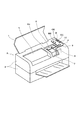
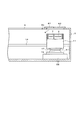
図1は、本発明の一実施形態のインクジェット式記録装置を示す。 FIG. 1 shows an ink jet recording apparatus according to an embodiment of the present invention.
この記録装置は、開閉可能なケースカバー1と、ケース本体2とからなるケース3に、
後述する印刷機構を収容して構成され、ケース本体2には印刷領域と非印刷領域とを区分
するように枠2cを挟んで2つの窓5、6が形成されている。
This recording apparatus includes a case 3 including a case cover 1 that can be opened and closed and a
The case
非印刷領域に形成された窓6は、キャリッジ11に搭載された噴射ヘッドに供給する液
体を貯留する液体カートリッジとしてのインクカートリッジ7、8の何れか一方のみの上
面が全て露出可能で、他方のインクカートリッジの少なくとも一部がケース本体2にカバ
ーされるようにそのサイズと形状が選択されている。またケースカバー1が閉じられたと
き、ケース本体2の露出する領域には、操作パネル9が設けらていて、ここに電源スイッ
チP、インクカートリッジ交換指令スイッチIC、ヘッドクリーニング指令スイッチCC
の他に、ラインフィードやリセットスイッチR等が、また黒及びカラーインクカートリッ
ジのインクエンド表示器BE、CEが配置されている。
The
In addition, a line feed, a reset switch R, and the like, and ink end indicators BE and CE for black and color ink cartridges are arranged.
図2は、上述した印刷機構の概要を示す。 FIG. 2 shows an overview of the printing mechanism described above.
キャリッジ11は、タイミングベルト12によりキャリッジ駆動モータ13に接続され
ていて、ガイド部材14に案内されて主走査方向であるプラテン15と平行な方向に往復
移動するように構成されている。キャリッジ11は、その記録用紙16と対向する面に、
印刷領域(図中、左側)にインクを噴射するノズルを有する噴射ヘッドとしての記録ヘッ
ド17が固定されている。上記記録ヘッド17は、前述の黒インクインクカートリッジ7
、カラーインクカートリッジ8からインクの供給を受けて記録用紙16にインク滴を吐出
して印刷する。
The
A
When ink is supplied from the
非印字領域に配置されたキャッピングユニット19は、記録ヘッド17のノズル面をキ
ャッピングするキャップ部材51をスライダに搭載し、モータ22により駆動されるポン
プユニット23にチューブ部材20を介して接続されて負圧の供給を受けるように構成さ
れている。
The capping
キャップ部材51は、記録ヘッド17のノズル開口面を1つの空間で封止できるサイズ
を備え、ゴムなどの弾性材料をカップ状に成形されており、非印字時には記録ヘッド17
のノズル開口面をキャッピングし、また吐出能力回復操作時には、ポンプユニット23の
負圧により記録ヘッド17からインクを強制的に排出させることができるように構成され
ている。また、キャッピングユニット19の近傍には、図示しない駆動源からの動力によ
り記録ヘッド17のノズル開口面にワイピングブレードを当接させるワイピングユニット
50が配置されている。
The
The nozzle opening surface is capped, and the ink can be forcibly discharged from the
図3は上記ポンプユニット23に設けられる吸引ポンプとしてのチューブポンプ10の
内部構造を示す。
FIG. 3 shows the internal structure of the
このチューブポンプ10は、回転体である回転板25に支持されたローラ部材21と、
円環状の湾曲部を有する可撓性のチューブ部材20を有し、上記チューブ部材20の両端
を同方向に引き出して同一平面内で束ねる形式のものである。上記チューブ部材20の吸
引方向の上流端は記録ヘッド17のノズル面を封止するキャップ部材21に接続され、吸
引方向の下流端は廃液タンク49に接続されている。
The
It has a
上記チューブ部材20の円環状部20aは、断面略C字状に形成されたガイド部材であ
るポンプフレーム24の内周面に沿って配置されることにより、円環状部20aの外周が
ポンプフレーム24によって支持されている。そして、上記円環状部20aの中に円環状
部20aと同心状に回転板25が配置されている。上記回転板25は、その外周が円環状
部20aの内周面と所定のクリアランスを維持した状態で軸心Cを中心にして回転するよ
うになっている。なお、上記回転板25を回転させる駆動源であるモータ22は、紙送り
機構のモータ等が兼用されている。
The
上記ローラ部材21は、回転板25の外周部近傍に形成された長穴18に回転可能に軸
支されている。回転板25が正転(吸引方向;矢印A)すると、まずローラ部材21は長
穴18の吸引方向の上流側端部に移動する。そしてさらに回転板25を正転させるとロー
ラ部材21は長穴18の上流側端部に押されるので回転板25とともに回転する。これに
より、上記回転板25が軸心Cを中心に回転することにより、ローラ部材21が円環状部
20aの内周面に沿って公転する。この公転により、ローラ部材21がチューブ部材20
の円環状部20aの内周を転動するようになっている。
The
It rolls on the inner periphery of the
ここで、長穴18は、円周方向の吸引方向上流側の端部と、吸引方向下流側の端部とで
は軸心Cからの距離が異なるよう角度が設けられている。吸引方向上流側の端部のほうが
吸引方向下流側の端部よりも軸心からの距離が長くなるよう設定されている。これにより
、ローラ部材21は、上記長穴18に沿って移動し、吸引方向の上流側端部に移動したと
きは径方向の外側に位置し、チューブ部材20の内面を完全に密着するようにチューブ部
材20を押し潰す。反対にローラ部材21が吸引方向の下流側端部に移動したときは径方
向の内側に位置し、ローラ部材21とチューブ部材20は僅かに接し、チューブ部材20
の内空間を十分確保するレリース状態とするようになっている(図において鎖線で示す位
置である)。
Here, the
The release state ensures a sufficient amount of the inner space (the position indicated by the chain line in the figure).
そして、回転板25が正転することにより、ローラ部材21がチューブ部材20の円環
状部20aの内周面を吸引方向に転動し、チューブ部材20が順次変形して復元すること
でチューブ部材20の上流側に負圧が発生するようになっている。この負圧の作用により
記録ヘッド17のノズル面に形成されたノズル開口48からインクが強制的に吸引され、
吸引されたインクは吸引方向に流れて下流の廃液タンク49に導入されるようになってい
る。
Then, when the
The sucked ink flows in the suction direction and is introduced into the downstream
このような構造により、回転板25が正転すると、ローラ部材21は吸引方向の上流側
端部に移動してチューブ部材20を押し潰し復元することで、上述したようにインクの吸
引が行われるようになっている。反対に、回転板25が逆転(矢印B)すると、ローラ部
材21は吸引方向の下流側端部に移動してチューブ部材20を押し潰さないようにして回
転するので負圧を発生せず、インクを吸引しないようになっている。
With such a structure, when the
一方、上記チューブ部材20の湾曲部である円環状部20aには、回転板25の正転時
においてローラ部材21の押圧による変形量が不十分となるリーク領域が設けられている
。
On the other hand, the
図4に示すように、この例では、上記チューブ部材20は、回転板25の外周に沿うよ
うに円環状に湾曲形成され、両端部を揃えて一方向に引き出されている。このチューブ部
材20が束ねられた領域(LA)は、チューブ部材20が外側に向かって延びている部分
であり、外側にガイド部材であるポンプフレーム24が存在しないため、ローラ部材21
で内側から押圧してチューブ部材20を変形させたとしても、負圧を発生させるだけの変
形量にならず、負圧がリークする領域である。そして、上記リーク領域LAの中心すなわ
ちチューブ部材20が束ねられた箇所にある略三角形の隙間の中心がリークポイントLP
である。
As shown in FIG. 4, in this example, the
Even if the
It is.
図5は、本実施形態におけるチューブポンプ10の外観を示した斜視図であり、図中の
符号24はポンプフレームを示し、このポンプフレーム24の内部に、図4に示したチュ
ーブ部材20の円環状部20aが収納されている。即ち、ポンプフレーム24の内面に、
可撓性のチューブ部材20の外形を円環状に規制するガイド部材としての支持面が形成さ
れている。
FIG. 5 is a perspective view showing the appearance of the
A support surface is formed as a guide member that regulates the outer shape of the
図に示すように、ポンプフレーム24の一側面から、ローラ部材21の公転動作に伴っ
て回転する回転板25の回転軸(図示せず)と一体に回転する検出用回転軸26が突出し
ている。この検出用回転軸26の先端には回転円板27が取り付けられており、この回転
円板27には切欠部27aが形成されている。
As shown in the figure, a
上記回転円板27の近傍には、回転円板27の回転動作の位相を検出するための光セン
サ28が、その発光部28a及び受光部28bによって回転円板27を非接触にて挟み込
むようにして配置されている。この光センサ28は、回転円板27の切欠部27aにおけ
る検出信号の変化に基づいて回転円板27の回転動作の位相を検出する。
In the vicinity of the
そして、上記検出用回転軸26、回転円板27及び光センサ28は、公転動作するロー
ラ部材21の位相情報を検出する位相検出手段29を構成している。すなわち、回転板2
5と回転円板27は同軸状に同時回転することから、回転円板27の位相を検出すること
により、回転板25の位相すなわち公転するローラ部材21の位相を検出できるのである
。
The
5 and the
ここで、光センサ28の検出信号がオンになるのは、回転円板27の切欠部27aが光
センサ28の位置に来て、発光部28aから放射された光が切欠部27aを通過して受光
部28bに到達する場合である。一方、光センサ28の検出信号がオフになるのは、回転
円板27の切欠部27a以外の部分が光センサ28の位置に来て、発光部28aから放射
された光が回転円板27で遮断されて受光部28bに到達しない場合である。
Here, the detection signal of the
したがって、この位相検出手段29では、光が回転円板27で遮断されて光センサ28
の検出信号がオフの状態からモータ22すなわち回転板25を正転させると、光が切欠部
27aを通過した時点で光センサ28の検出信号がオンに切り換わり、引き続き正転させ
て切欠部27aを通過して再び光が回転円板27で遮断されると光センサ28の検出信号
がオフに切り換わる。
Therefore, in this
When the
そして、この例では、モータ22すなわち回転板25が正転している状態で、光センサ
28の検出信号がオンからオフに切り換わるときに、ローラ部材21がリークポイントL
Pに位置するよう、回転板25および回転円板27の位置関係を設定している。
In this example, when the detection signal of the
The positional relationship between the
図6は、インクカートリッジ7、8、記録ヘッド17、キャップ部材51、チューブポ
ンプ10における流路構造を説明する図である。
FIG. 6 is a diagram illustrating the flow path structure in the
ブラック用のインクカートリッジ7は、記録ヘッド17の上面に設けられたインク供給
針52がインクカートリッジ7の下面に設けられたインク供給口54に挿入されることに
より記録ヘッド17に搭載される。同様に、カラー用のインクカートリッジ8は、イエロ
ーインク、マゼンタインク、シアンインクをそれぞれ供給する3つのインク供給口54に
、イエローインク、マゼンタインク、シアンインクをそれぞれ導入するためのインク供給
針52が挿入されることにより記録ヘッド17に搭載される。
The
記録ヘッド17に搭載されたインクカートリッジ7,8のインクは、インク供給針52
の先端に穿設されたインク導入孔53から中空のインク供給針52の内部通路に導入され
、記録ヘッド17に設けられた流路55を通り、アクチュエータ56の作用によってノズ
ル開口48から吐出され、印刷やフラッシングが行われる。
The ink in the
Is introduced into the internal passage of the hollow
一方、吸引によるクリーニングの際は、キャップ部材51で記録ヘッド17のノズル面
をキャッピングし、チューブポンプ10の回転板25を吸引方向Aに回転させることによ
り、ローラ部材21がチューブ部材20の円環状部20aの内周面を吸引方向に転動し、
チューブ部材20が順次変形してチューブ部材20の上流側すなわちキャップ部材51の
内部空間に負圧が発生するようになっている。この負圧の作用により記録ヘッド17のノ
ズル面に形成されたノズル開口48からインクが強制的に吸引され、吸引されたインクは
吸引方向に流れて下流の廃液タンク49に導入されるようになっている。
On the other hand, when cleaning by suction, the nozzle surface of the
The
そして、この記録装置は、上記キャップ部材51、チューブ部材20、チューブポンプ
10により記録ヘッド17のノズルの外側の空間を閉空間となるように封止する封止手段
が構成され、制御手段としての後述するシーケンス選択手段45およびインクカートリッ
ジ交換制御手段、キャリッジモータ制御手段36およびポンプ制御手段64は、インクカ
ートリッジ交換指令スイッチICからのインクカートリッジ7,8の交換指令を受け付け
たときに上記封止手段により記録ヘッド17のノズルを封止状態にするよう制御する。
The recording apparatus includes a sealing unit that seals the space outside the nozzles of the
すなわち、上記封止手段は、記録ヘッド17のノズル面をキャッピングするキャップ部
材51を含んで構成され、上記制御手段は、キャップ部材51でノズル面をキャッピング
することによりノズル開口48をノズル外側の空間が閉空間となるように封止状態にする
。
That is, the sealing means includes a
上記封止手段は、上記キャップ部材51内の空間を外部に連通させる連通路としてのチ
ューブ部材20を閉塞する閉塞機構をさらに含んで構成してもよい。上記閉塞機構は、後
述するローラ部材21、回転板25、ポンプフレーム24、位相検出手段29等のチュー
ブ部材20を押圧して押し潰すために機能する部材を含んで構成されている。そして、上
記制御手段は、キャップ部材51でノズル面をキャッピングするとともに、閉塞機構でチ
ューブ部材20を閉塞することによりノズル開口48を封止状態にする。
The sealing means may further include a closing mechanism that closes the
また、上記連通路は、上記ノズル面をキャッピングしたキャップ部材51の内部空間に
負圧を与えるチューブポンプ10の可撓性のチューブ部材20によって形成されている。
上記チューブポンプ10は、上述したように、ローラ部材21が支持された回転体として
の回転板25を回転させて、湾曲状に配置されたチューブ部材20の内周に沿ってローラ
部材21を転動させて負圧を発生させるものであり、上記ローラ部材21は回転体の正転
(吸引方向Aへの回転)によりチューブ部材20を押圧して押し潰し、回転板25の逆転
(解除方向Bへの回転)によりチューブ部材20への押圧力が解除されるよう上記回転板
25に支持されている。そして、上記制御手段は、上記回転板25を正転させてローラ部
材21がチューブ部材20を押し潰した状態で回転板25を停止することによりチューブ
部材20を閉塞してノズル開口48を封止状態にする。このように、上記連通路としての
チューブ部材20は、上記ノズル面をキャッピングしたキャップ部材51の内部空間に負
圧を与えるポンプの流路であり、上記制御手段は、上記ポンプの流路を閉塞してノズル開
口48を封止状態にする
The communication path is formed by the
As described above, the
さらに、上記制御手段は、位相検出手段29で検出された公転するローラ部材21の位
相情報に基づいて、回転板25の正転時においてローラ部材21の押圧による変形量が不
十分となるリーク領域LAを外れた領域でローラ部材21を停止させることによりチュー
ブ部材20を閉塞してノズル開口48を封止状態にしてもよい。
Further, the control means is based on the phase information of the revolving
このように、インクカートリッジ7、8の交換指令を受け付けたときに封止手段により
記録ヘッド17のノズル開口48を封止状態にすることから、新しいインクカートリッジ
7、8を装着する際に、インクカートリッジ7、8と記録ヘッド17との接合部分である
インク供給針52の部分に加圧力が発生しても、ノズル開口48の外側に空間が閉空間と
なっており、ノズル開口48からインクが滲み出すことがない。このため、インクカート
リッジ7、8の交換後に、ノズル開口48からインクが滲み出したことで壊れたノズル開
口48のインクメニスカスを回復させるためのインク吸引動作を行う必要もなくなること
から、無駄にインクを排出することもなくなるうえ、吸引後のワイピングやフラッシング
吐出等の動作も不要になり、カートリッジ交換シーケンスを簡略化して交換に要する時間
も短縮することができる。
In this way, since the
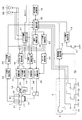
図7は、上記記録装置のインクカートリッジ交換操作や、目詰まり解消を実行する制御
装置の一実施例を示す。
FIG. 7 shows an embodiment of a control device for executing the ink cartridge replacement operation and clogging elimination of the recording apparatus.
インクカートリッジ着脱検出手段30は、キャリッジ11の各インクカートリッジ7、
8が対向する位置、この実施例ではキャリッジ11のカートリッジ受け面にインクカート
リッジ7、8により押圧操作されるスイッチ31、32からの信号を受けてインクカート
リッジ7、8の装着、及び取り外しを検出するものである。インクカートリッジ交換判断
手段33は、インクカートリッジ着脱検出手段30からの信号により、インクカートリッ
ジ7、8が交換されたか、否かを判断するものである。
The ink cartridge attachment / detachment detection means 30 includes the
In this embodiment, the mounting and removal of the
キャリッジ位置検出手段34は、キャリッジ位置検出器35からの信号に基づいてキャ
リッジ11が、少なくともホームポジション(記録ヘッド17がキャップ部材51に対向
する位置である)、第1のインクカートリッジ7が窓6に対向する第1の交換ポジション
、第2のインクカートリッジ8が窓6に対向する第2の交換ポジション、フラッシング動
作の際に記録ヘッド17からのインク滴を受けることができるフラッシング位置(この実
施例ではキャップ部材51に対向する位置)、及び記録ヘッド17がワイピングユニット
50によるワイピングやラビングを受けることができるクリーニング位置に移動した場合
等に、その位置についての信号を出力する。
In the carriage position detecting means 34, the
キャリッジモータ制御手段36は、シーケンス選択手段45からの制御を受けてキャリ
ッジ11を印刷のために往復移動させる他、後述する吸引制御手段39、インクカートリ
ッジ交換制御手段63及びキャリッジ位置検出手段34からの信号に基づいてキャリッジ
11を前述のホームポジション、第1の交換ポジション、第2の交換ポジション、フラッ
シング位置、及びクリーニング位置に移動させ、さらにインクカートリッジ7、8の交換
が完全な状態で終了した場合には、通常よりも低トルク、もしくは低速、またはこれらの
組み合わせた状態でキャリッジ11をホームポジションに移動させる。
The carriage motor control means 36 receives the control from the sequence selection means 45 and reciprocates the
印字・フラッシング制御手段37は、ホストからの印刷データに基づいてヘッド駆動手
段38から記録ヘッド17にインク滴吐出のための駆動信号を出力して印刷動作を制御す
る他に、フラッシング位置に存在する記録ヘッド17に前述と同様の駆動信号を出力して
、全てのノズル開口からインク滴を吐出させて増粘したインクをインク受けに吐出させる
フラッシング動作を制御するものである。
The printing / flushing control means 37 outputs a drive signal for ejecting ink droplets from the head driving means 38 to the
吸引制御手段39は、シーケンス選択手段45による制御を受けて記録ヘッド17をキ
ャッピングユニット19により封止させ、ポンプ駆動手段40によりポンプユニット23
のチューブポンプ10の吸引力や、吸引時間を制御して、インク吐出能力回復のために記
録ヘッド17からインクを吸引、排出させるものである。
The suction control means 39 is controlled by the sequence selection means 45 and seals the
The suction force and suction time of the
インク残量検出手段41は、印刷により形成するドット数や、フラッシング動作により
吐出するインク滴の数や、クリーニング動作により消費されるインク量を積算して、イン
クカートリッジ7、8のインク残量を算出する。そして、インクカートリッジ7、8が交
換された場合にはその積算値をリセットする他、少なくとも吸引によるクリーニングが指
令された場合に、双方のインクカートリッジ7、8のインク残量をチェックし、チェック
したインク残量がクリーニングで消費されるインク量よりも少ない場合に、インクカート
リッジ7、8をインクエンドと判断する。
The ink remaining
電源遮断検出手段42は、電源スイッチPのオン−オフを検出してその状態を示す信号
を出力するとともに、電源をオフとする操作が行われた場合には所定の後処理を実行した
後、装置への電源の供給を停止するものである。ケース開放検出手段43で、ケースカバ
ー1の開閉に応動するスイッチ44からの信号によりケースカバー1が開放されたか否か
を示す信号を出力する。
The power
シーケンス選択手段45は、操作パネル9のインクカートリッジ交換指令スイッチIC
、クリーニング指令スイッチCC、電源遮断検出手段42、ケース開放検出手段43、イ
ンク残量検出判定手段41、リセットスイッチR及びホストからの信号を受け、後述する
フローチャートに基づいて全体の処理や、さらには電源オン処理、電源オフ処理、クリー
ニング処理、インク残量チェック処理、印刷処理、インクカートリッジ交換処理等の動作
を統括し、またクリーニング処理に伴って生じる各種の状態を電源オフ処理時に吸引状態
記憶手段46に格納するものである。
The sequence selection means 45 is provided with an ink cartridge replacement command switch IC on the operation panel 9.
The cleaning command switch CC, the power interruption detection means 42, the case opening detection means 43, the ink remaining amount detection determination means 41, the reset switch R, and signals from the host are received, and the entire process or Supervises operations such as power-on processing, power-off processing, cleaning processing, ink remaining amount check processing, printing processing, ink cartridge replacement processing, etc., and suction state storage means for various states caused by cleaning processing during power-
吸引状態記憶手段は、工場出荷時点では初期充填フラッグをオフとしたデータが格納さ
れており、ユーザサイドで初期充填が終了した段階で初期充填フラッグをオンとし、また
インクカートリッジ7、8に対する吸引操作の状態やインク残量等を格納するエリアを備
えている。なお、図中符号47は、キャリッジ駆動モータ13を駆動するキャリッジモー
タ駆動手段を示す。
The suction state storage means stores data indicating that the initial filling flag is turned off at the time of shipment from the factory, turns on the initial filling flag when the initial filling is completed on the user side, and performs a suction operation on the
インクカートリッジ交換制御手段63は、シーケンス選択手段45による制御を受けて
インクカートリッジ交換処理を制御する。すなわち、インク残量検出判定手段41がイン
クエンドと判断すると、インクエンド表示器BE,CEに信号を送り、LEDランプを点
灯させる等の方法でユーザにインクエンドサインを報知する。ユーザはインクエンドの報
知を受けてインクカートリッジ交換指令スイッチICを押すと、シーケンス選択手段45
がインクカートリッジ7,8の交換指令を受け付け、インクカートリッジ交換制御手段6
3に制御信号を送り、上記キャップ部材51、チューブ部材20、チューブポンプ10等
により記録ヘッド17のノズルを封止する封止手段により記録ヘッド17のノズル開口4
8を封止状態にするよう制御する。
The ink cartridge
Accepts the replacement command for the
3, and the nozzle opening 4 of the
8 is controlled to be in a sealed state.
このノズル開口48の封止は、まず、キャリッジモータ制御手段36によりキャリッジ
11の移動制御を行って、インクエンドが検知された方のインクカートリッジ7、8が窓
6と対面する第1の交換ポジションまたは第2の交換ポジションにキャリッジ11を移動
させる。後述するが、この実施形態では、キャリッジ11が第1の交換ポジションまたは
第2の交換ポジションに移動することにより、キャップ部材51の上縁がノズル面に密着
してキャッピングが行われる。
The
そして、第1の交換ポジションまたは第2の交換ポジションに移動してキャッピングが
行われると、ポンプ制御手段64の制御によりチューブポンプ10の回転板25を正回転
(吸引方向A)に少しずつ回転させ、位相検出手段29でローラ部材21の位置を検出し
てローラ部材21の押圧によるチューブ部材21の変形量が不十分となるリーク領域LA
を外れた領域でローラ部材21を停止させる。
Then, when capping is performed by moving to the first exchange position or the second exchange position, the
The
すなわち、モータ22すなわち回転板25が正転している状態で、光センサ28の検出
信号がオンからオフに切り換わるときがローラ部材21がリークポイントLPに位置して
るので、回転板25を少しずつ正転させて光センサ28の検出信号がオンからオフに切り
換わってから所定回転(例えば4分の1回転〜2分の1回転くらい)回したところでモー
タ22を停止する。
That is, the
この状態で、記録ヘッド17のノズル面がキャップ部材51でキャッピングされるとと
もに、上記キャップ部材51内の空間を外部に連通させる連通路であるチューブ部材20
が閉塞されてノズル開口48が封止状態になる。
In this state, the nozzle surface of the
Is closed and the
この状態で、インクカートリッジ交換制御手段63は、例えばインクエンド表示器BE
,CEに信号を送り、LEDランプを点滅させる等の方法でユーザにインクカートリッジ
交換準備完了のサインを報知し、ユーザにインクカートリッジの交換を行わせる。
In this state, the ink cartridge replacement control means 63 performs, for example, the ink end indicator BE.
, CE to notify the user of a sign of ink cartridge replacement preparation completion by sending a signal to CE and blinking the LED lamp, etc., and cause the user to replace the ink cartridge.
インクカートリッジ交換が終了したユーザは、インクカートリッジ交換指令スイッチI
Cを再び押すことによりインクカートリッジ交換終了信号を入力する。シーケンス選択手
段45は、インクカートリッジ交換終了信号を受け付けると、インクカートリッジ交換制
御手段63に制御信号を送り、キャリッジモータ制御手段36によるキャリッジ11の移
動制御を行って、キャリッジ11をホームポジションに移動させる。
The user who has completed the ink cartridge replacement is notified of the ink cartridge replacement command switch I
By pressing C again, an ink cartridge replacement end signal is input. When the
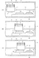
図8−1、図8−2は、キャリッジ11のポジションを説明する図である。
8A and 8B are diagrams for explaining the position of the
図8−1(A)は、キャリッジ11が印刷領域に存在する状態を示しており、キャリッ
ジ11およびインクカートリッジ7、8は、印刷領域の窓5に対面したところに存在して
いる。
FIG. 8A shows a state in which the
図8−1(B)は、第2のインクカートリッジ8だけが窓6に対面する第2の交換ポジ
ションであり、第2のインクカートリッジ8だけが窓6から抜き差し可能で、第1のイン
クカートリッジ7は枠2Cに対面して抜き差しが不可能な状態である。
FIG. 8B is a second replacement position in which only the
図8−1(C)は、第1のインクカートリッジ7だけが窓6に対面する第1の交換ポジ
ションであり、第1のインクカートリッジ7だけが窓6から抜き差し可能で、第2のイン
クカートリッジ8はケース本体2の天井面に対面して抜き差しが不可能な状態である。
FIG. 8C is a first replacement position in which only the
図8−2(D)は、ホームポジションであり、第1のインクカートリッジ7および第2
のインクカートリッジ8はケース本体2の天井面に対面して抜き差しが不可能な状態であ
る。
FIG. 8-2 (D) shows the home position, where the
The
キャッピングユニット19は、ガイドユニット57に左右スライド可能に支持されてお
り、最も印刷領域側では若干高さが下がってキャップ部材51がノズル面から離れた状態
となる。この状態のキャップ部材51に対してノズル面が対面するまでキャリッジ11を
移動させたポジションがフラッシングポジションであり、ノズル開口48からキャップ部
材51に対してフラッシング吐出が行われる。
The capping
さらにキャリッジ11をホームポジション側に移動させると、キャリッジ11の側面が
キャッピングユニット19のホームポジション側の端部に立設された当接部材65に当接
し、キャッピングユニット19をホームポジション側に押して移動させる。このとき、キ
ャッピングユニット19はノズル面側に迫り上がりながら移動し、第2の交換ポジション
、第1の交換ポジションおよびホームポジションでは、キャップ部材51の上縁がノズル
面に密着してキャッピングされた状態となる。
When the
すなわち、キャッピングユニット19は、キャリッジ11によってホームポジション側
に押されて移動するときにキャッピング動作を行うよう、図示の矢印の軌跡を描くよう動
作する。このようなキャッピングユニット19の動作は、例えば、ガイドユニット57内
に上記軌跡のようなラインで設けられたガイドレール上にキャッピングユニット19をス
ライド可能に搭載することにより実現することができるが、この機構に限るものではなく
、各種の機構・構造を採用することができる。
That is, the capping
このような構成により、上記制御手段は、インクカートリッジ7,8の交換指令を受け
付けたときに所定ポジションとしてのインクカートリッジ7,8の交換を可能とするよう
ケース本体2に窓6が設けられた第1の交換ポジションまたは第2の交換ポジションにキ
ャリッジ11を移動させ、記録ヘッド17のノズルを封止状態にするよう制御する。
With such a configuration, the control means is provided with the
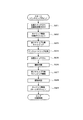
図9は、本実施形態の記録装置におけるインクカートリッジ交換処理を説明するフロー
チャートである。
FIG. 9 is a flowchart for explaining ink cartridge replacement processing in the recording apparatus of the present embodiment.
まず、インク残量検出判定手段41がインクエンドと判断すると、インクエンド表示器
BE,CEに信号を送り、LEDランプを点灯させる等の方法でユーザにインクエンドサ
インを報知する。このとき、ブラックインク用のインクカートリッジ7がインクエンドで
あれば、インクエンド表示器BEのランプが点灯し、カラーインク用のインクカートリッ
ジ8がインクエンドであれば、インクエンド表示器CEのランプが点灯することにより、
ユーザに2つのインクカートリッジ7、8のうちどちらがインクエンドになったかを報知
する。
First, when the ink remaining amount detection determination means 41 determines that the ink has ended, a signal is sent to the ink end indicators BE and CE to notify the user of the ink end sign by a method such as turning on the LED lamp. At this time, if the
The user is notified which of the two
このとき、インク残量検出判定手段41は、ブラックインク用のインクカートリッジ7
がインクエンドであれば、ブラックインク用のインクカートリッジ7がインクエンドであ
る旨の信号をシーケンス選択手段45に送り、カラーインク用のインクカートリッジ8が
インクエンドであれば、カラーインク用のインクカートリッジ8がインクエンドである旨
の信号をシーケンス選択手段45に送る。
At this time, the ink remaining amount detection judging means 41 is provided with the
If the ink end is the ink end, a signal indicating that the
ユーザは、インクエンドの報知を受けてインクカートリッジ交換指令スイッチICを押
して、インクカートリッジの交換作業を開始する(S1)。ユーザがインクカートリッジ
交換指令スイッチICを押すことにより、シーケンス選択手段45がインクカートリッジ
7,8の交換指令を受け付ける。このとき、シーケンス選択手段45は、インク残量検出
判定手段41からブラックインク用のインクカートリッジ7がインクエンドである旨の信
号を受領していれば、ブラックインク用のインクカートリッジ7の交換指令をインクカー
トリッジ交換制御手段63に送信する。カラーインク用のインクカートリッジ8がインク
エンドである旨の信号を受領していれば、カラーインク用のインクカートリッジ8の交換
指令をインクカートリッジ交換制御手段63に送信する。
In response to the ink end notification, the user presses the ink cartridge replacement command switch IC to start the ink cartridge replacement operation (S1). When the user presses the ink cartridge replacement command switch IC, the
インクカートリッジ交換制御手段63は、インクカートリッジ7,8の交換指令を受け
付けると、キャリッジモータ制御手段36に制御信号を送ってキャリッジ11の移動制御
を行い、キャリッジ11を所定の交換ポジションに移動させる(S2)。このとき、ブラ
ックインク用のインクカートリッジ7の交換指令を受領していれば、ブラックインク用の
インクカートリッジ7が窓6に対面する第1の交換ポジションに移動させ、カラーインク
用のインクカートリッジ8の交換指令を受領していれば、カラーインク用のインクカート
リッジ8が窓6に対面する第2の交換ポジションに移動させる。
When the ink cartridge replacement control means 63 receives a replacement command for the
このとき、上述したように、キャリッジ11が第1の交換ポジション・第2の交換ポジ
ションいずれの位置であっても、キャップ部材51の上縁がノズル面に密着してキャッピ
ングが行われる。
At this time, as described above, capping is performed with the upper edge of the
つぎに、インクカートリッジ交換制御手段63は、ポンプ制御手段64に制御信号を送
ってチューブポンプ10を駆動し、ポンプ制御手段64の制御によりチューブポンプ10
の回転板25を正回転(吸引方向A)に少しずつ回転させ、位相検出手段29でローラ部
材21の位置を検出してローラ部材21の押圧によるチューブ部材21の変形量が不十分
となるリーク領域LAを外れた領域でローラ部材21を停止させ、チューブ部材20をロ
ーラ部材21で閉塞する(S3)。これにより、記録ヘッド17のノズル面がキャップ部
材51でキャッピングされるとともに、上記キャップ部材51内の空間を外部に連通させ
るチューブ部材20が閉塞されてノズル開口48が封止状態になる。
Next, the ink cartridge replacement control means 63 sends a control signal to the pump control means 64 to drive the
The
ついで、インクカートリッジ交換制御手段63は、インクエンド表示器BE,CEに信
号を送り、LEDランプを点滅させる等の方法でユーザにインクカートリッジ交換準備完
了のサインを報知し、ユーザは、インクカートリッジの交換作業を行う(S4)。
Next, the ink cartridge replacement control means 63 sends a signal to the ink end indicators BE and CE to notify the user of the ink cartridge replacement preparation sign by flashing the LED lamp or the like. Exchange work is performed (S4).
そして、インクカートリッジ交換が終了したユーザは、インクカートリッジ交換指令ス
イッチICを再び押すことによりインクカートリッジ交換終了信号を入力する(S5)。
シーケンス選択手段45は、インクカートリッジ交換終了信号を受け付けると、インクカ
ートリッジ交換制御手段63に制御信号を送り、キャリッジモータ制御手段36によるキ
ャリッジ11の移動制御を行って、キャリッジ11をホームポジションに移動させ(S6
)、一連のインクカートリッジ交換処理が終了し、印刷を再開する。
Then, the user who has completed the ink cartridge replacement inputs the ink cartridge replacement end signal by pressing the ink cartridge replacement command switch IC again (S5).
When the
), A series of ink cartridge replacement processing is completed, and printing is resumed.
上記実施形態の液体噴射装置によれば、つぎのような作用効果を奏する。 According to the liquid ejecting apparatus of the above embodiment, the following operational effects are obtained.
すなわち、インクカートリッジ7、8の交換指令を受け付けたときに封止手段により記
録ヘッド17のノズルを封止状態にすることから、新しいインクカートリッジ7、8を装
着する際に、インクカートリッジ7、8と記録ヘッド17との接合部分において加圧力が
発生しても、ノズル開口48からインクが滲み出すことがなく、メニスカスの破壊を防げ
る。このため、インクカートリッジ7、8の交換後に、メニスカスを復活させるクリーニ
ング動作を行う必要もなくなることから、無駄にインクを排出することもなくなるうえ、
吸引後のワイピングやフラッシング吐出等の動作も不要になり、カートリッジ交換シーケ
ンスを簡略化して交換に要する時間も短縮することができる。
In other words, since the nozzles of the
Operations such as wiping after suction and flushing discharge become unnecessary, and the cartridge replacement sequence can be simplified and the time required for replacement can be shortened.
また、上記封止手段は、記録ヘッド17のノズル面をキャッピングするキャップ部材5
1を含んで構成され、上記制御手段は、キャップ部材51でノズル面をキャッピングする
ことによりノズル開口48を封止状態にするため、吸引動作や装置休止時に使用するキャ
ップ部材51によりノズル開口48を封止するため、装置の設備を有効利用して設備効率
がよい。
The sealing means is a
1, and the control means capping the nozzle surface with the
また、上記封止手段は、上記キャップ部材51内の空間を外部に連通させるチューブ部
材20を閉塞する閉塞機構をさらに含んで構成され、上記制御手段は、キャップ部材51
でノズル面をキャッピングするとともに、閉塞機構でチューブ部材20を閉塞することに
よりノズル開口48を封止状態にするため、チューブ部材20の閉塞によりキャッピング
したキャップ部材51内が完全に密閉空間となるため、インクカートリッジ7、8を取り
付けるときに記録ヘッド17との接合部に加わる加圧力に対抗するため、ノズル開口48
からのインクの滲み出しが防止できる。
The sealing means further includes a closing mechanism that closes the
Since the nozzle surface is capped and the
It is possible to prevent the ink from bleeding out.
上記連通路としてのチューブ部材20は、上記ノズル面をキャッピングしたキャップ部
材51の内部空間に負圧を与えるポンプの流路であり、上記制御手段は、上記ポンプの流
路を閉塞してノズル開口48を封止状態にするため、ポンプの制御によりノズルを封止す
るため、装置の設備を有効利用して設備効率がよい。
The
また、上記チューブ部材20は、上記ノズル面をキャッピングしたキャップ部材51の
内部空間に負圧を与えるチューブポンプ20の可撓性のチューブ部材20であり、
上記チューブポンプ10は、ローラ部材21が支持された回転板25を回転させて、湾
曲状に配置されたチューブ部材20の内周に沿ってローラ部材21を転動させて負圧を発
生させるものであり、上記ローラ部材21は回転板25の正転によりチューブ部材20を
押圧して押し潰し、回転板25の逆転によりチューブ部材20への押圧力が解除されるよ
う上記回転板25に支持され、
上記制御手段は、上記回転板25を正転させてローラ部材21がチューブ部材20を押
し潰した状態で回転板25体を停止することによりチューブ部材20を閉塞してノズル開
口48を封止状態にするため、
チューブポンプ10の構造を利用してノズル開口48の封止状態を形成するため、装置
の設備を有効利用して設備効率がよい。
The
The
The control means rotates the
Since the sealed state of the
また、上記制御手段は、位相検出手段29で検出された公転するローラ部材21の位相
情報に基づいて、回転板25の正転時においてローラ部材21の押圧による変形量が不十
分となるリーク領域LAを外れた領域でローラ部材21を停止させることによりチューブ
部材20を閉塞してノズル開口48を封止状態にするため、キャッピングしたキャップ部
材51内が完全に密閉空間となり、ノズル開口48からのインクの滲み出しが有効に防止
できる。
Further, the control means is based on the phase information of the revolving
また、上記記録ヘッド17を主走査方向に移動させるキャリッジ11をさらに備え、上
記制御手段は、インクカートリッジ7、8の交換指令を受け付けたときに所定ポジション
にキャリッジ11を移動させ、上記封止手段により記録ヘッド17のノズル開口48を封
止状態にするよう制御するため、一定の所定ポジションにおいてノズル開口48の封止を
行うことから一定のシーケンスによる制御が可能となる。
Further, a
また、上記所定ポジションは、インクカートリッジ7、8の交換を可能とするよう外側
ケースに窓部が設けられた交換ポジションであるため、交換ポジションにおいてノズル開
口48を封止状態にすることから、ノズル開口48の封止状態を保ったままインクカート
リッジ7、8の交換を行うことができる。
Further, since the predetermined position is an exchange position in which the outer case is provided with a window so that the
図10〜図13は本発明の第2実施形態を示す。 10 to 13 show a second embodiment of the present invention.
この例は、ホームポジションに第1キャップ51aが設けられ、交換ポジションに第2
キャップ51bが設けられ、インクカートリッジ交換処理において上記第2キャップ51
bによりノズル開口48を封止するようにしたものである。
In this example, the
A
The
より詳しく説明すると、上記第1キャップ51aは第1キャッピングユニット19aに
設けられ、上記第2キャップ51bは第2キャッピングユニット19bに設けられている
。上記第1キャッピングユニット19aおよび第2キャッピングユニット19bは、それ
ぞれ昇降ユニット58により昇降可能に搭載され、図示しない円筒カム機構等による昇降
動作でキャッピングするようになっている。
More specifically, the
上記第1キャップ51aは、チューブポンプ10に接続されて内部空間に与えられた負
圧によりノズル開口48からインクを吸引・排出するものである。
The
上記第2キャップ51bは、内部空間を大気開放する流路であるチューブ部材20bに
開閉弁59が設けられ、開閉弁59を閉じた状態でキャッピングすることによりノズル開
口48を封止状態にするものである。キャッピングを解除するときには上記開閉弁59を
開けて内部空間を大気開放した状態で第2キャップ51bを下降させる。
The
この例では、2つのインクカートリッジ7、8が同時に窓6に対面するようになってお
り、交換ポジションは1箇所である。
In this example, the two
図10は、キャリッジ11のポジションを説明する図である。
FIG. 10 is a diagram illustrating the position of the
図10(A)は、キャリッジ11が印刷領域に存在する状態を示しており、キャリッジ
11およびインクカートリッジ7、8は、印刷領域の窓5に対面したところに存在してい
る。
FIG. 10A shows a state in which the
図10(B)は、第1のインクカートリッジ7と第2のインクカートリッジ8が窓6に
対面する交換ポジションであり、第1のインクカートリッジ7および第2のインクカート
リッジ8が窓6から抜き差し可能な状態である。
FIG. 10B shows an exchange position where the
図10(C)は、ホームポジションであり、第1のインクカートリッジ7および第2の
インクカートリッジ8はケース本体2の天井面に対面して抜き差しが不可能な状態である
。
FIG. 10C shows the home position, where the
第1のキャッピングユニット19aおよび第2のキャッピングユニット19bは、昇降
ユニット58に昇降可能に支持されている。
The
インクカートリッジ7,8の交換指令を受け付けたときに、キャリッジ11を交換ポジ
ションに移動させ、第2のキャッピングユニット19bを上昇させて第2キャップ51b
の上縁をノズル面に密着させてキャッピングすることにより、記録ヘッド17のノズル開
口48を封止状態にするよう制御する。すなわち、この実施形態では、上記第2キャップ
51b、チューブ部材20bおよび開閉弁59が本発明の封止手段として機能する。
When a replacement command for the
The
また、クリーニング指令を受け付けたときに、キャリッジ11をホームポジションに移
動させ、第1のキャッピングユニット19aを上昇させて第1キャップ51aの上縁をノ
ズル面に密着させてキャッピングし、チューブポンプ10を駆動することにより、記録ヘ
ッド17のノズル開口48からインクを吸引・排出する。
When the cleaning command is received, the
図12は、上記第2実施形態の記録装置のインクカートリッジ交換操作や、目詰まり解
消を実行する制御装置の一実施例を示す。
FIG. 12 shows an example of a control device that executes an ink cartridge replacement operation and clogging elimination of the recording apparatus of the second embodiment.
この例では、インクカートリッジ交換指令を受け付けたときに、チューブポンプによる
チューブ部材20の閉塞によりノズル開口48を封止するのではなく、第2キャップ51
bによるキャッピングによりノズル開口48を封止するため、インクカートリッジ交換制
御手段63からポンプ制御手段(図示せず)に制御信号が送られるようになっていない。
In this example, when the ink cartridge replacement command is received, the
Since the
そして、インクカートリッジ交換制御手段63は、ユーザがインクカートリッジ交換指
令スイッチICを押し、シーケンス選択手段45がインクカートリッジ7,8の交換指令
を受け付けると、インクカートリッジ交換制御手段63に制御信号を送り、上記第2キャ
ップ51b、チューブ部材20b、開閉弁59等により記録ヘッド17のノズル開口48
を封止状態にするよう制御する。
The ink cartridge replacement control means 63 sends a control signal to the ink cartridge replacement control means 63 when the user presses the ink cartridge replacement command switch IC and the sequence selection means 45 receives the replacement command for the
Is controlled to be in a sealed state.
このノズル開口48の封止は、まず、キャリッジモータ制御手段36によりキャリッジ
11の移動制御を行って、インクカートリッジ7、8が窓6と対面する交換ポジションに
キャリッジ11を移動させる。そして、昇降制御手段67によりキャップ昇降手段66を
制御して第2キャップ51bを上昇させ、第2キャップ51bの上縁をノズル面に密着さ
せてキャッピングする。
The
この状態で、ノズル開口48が封止状態になり、インクカートリッジ交換制御手段63
は、例えばインクエンド表示器BE,CEに信号を送り、LEDランプを点滅させる等の
方法でユーザにインクカートリッジ交換準備完了のサインを報知し、ユーザにインクカー
トリッジの交換を行わせる。
In this state, the
For example, a signal is sent to the ink end indicators BE and CE, and the LED lamp is blinked to notify the user of the ink cartridge replacement preparation completion sign so that the user can replace the ink cartridge.
インクカートリッジ交換が終了したユーザは、インクカートリッジ交換指令スイッチI
Cを再び押すことによりインクカートリッジ交換終了信号を入力する。シーケンス選択手
段45は、インクカートリッジ交換終了信号を受け付けると、インクカートリッジ交換制
御手段63に制御信号を送り、昇降制御手段67により第2キャップ51bを下降させて
キャッピングを解除するとともに、キャリッジモータ制御手段36によるキャリッジ11
の移動制御を行って、キャリッジ11をホームポジションに移動させる。
The user who has completed the ink cartridge replacement is notified of the ink cartridge replacement command switch I
By pressing C again, an ink cartridge replacement end signal is input. When the sequence selection means 45 receives the ink cartridge replacement end signal, the sequence selection means 45 sends a control signal to the ink cartridge replacement control means 63 and lowers the
The
それ以外は第1の実施形態と同様であるので説明を省略する。 Since other than that is the same as that of 1st Embodiment, description is abbreviate | omitted.
図13は、本実施形態の記録装置におけるインクカートリッジ交換処理を説明するフロ
ーチャートである。
FIG. 13 is a flowchart for explaining ink cartridge replacement processing in the recording apparatus of the present embodiment.
まず、インク残量検出判定手段41がインクエンドと判断すると、インクエンド表示器
BE,CEに信号を送り、LEDランプを点灯させる等の方法でユーザにインクエンドサ
インを報知する。このとき、ブラックインク用のインクカートリッジ7がインクエンドで
あれば、インクエンド表示器BEのランプが点灯し、カラーインク用のインクカートリッ
ジ8がインクエンドであれば、インクエンド表示器CEのランプが点灯することにより、
ユーザに2つのインクカートリッジ7、8のうちどちらがインクエンドになったかを報知
する。
First, when the ink remaining amount detection determination means 41 determines that the ink has ended, a signal is sent to the ink end indicators BE and CE to notify the user of the ink end sign by a method such as turning on the LED lamp. At this time, if the
The user is notified which of the two
ユーザは、インクエンドの報知を受けてインクカートリッジ交換指令スイッチICを押
して、インクカートリッジの交換作業を開始する(S21)。ユーザがインクカートリッ
ジ交換指令スイッチICを押すことにより、シーケンス選択手段45がインクカートリッ
ジ7,8の交換指令を受け付ける。
Upon receiving the ink end notification, the user presses the ink cartridge replacement command switch IC to start the ink cartridge replacement operation (S21). When the user presses the ink cartridge replacement command switch IC, the
インクカートリッジ交換制御手段63は、インクカートリッジ7,8の交換指令を受け
付けると、キャリッジモータ制御手段36に制御信号を送ってキャリッジ11の移動制御
を行い、キャリッジを所定の交換ポジションに移動させる(S22)。
When the ink cartridge replacement control means 63 receives a replacement command for the
ついで、インクカートリッジ交換制御手段63は、昇降制御手段67に制御信号を送り
、昇降制御手段67によりキャップ昇降手段66を制御して第2キャップ51bを上昇さ
せ、第2キャップ51bの上縁をノズル面に密着させてキャッピングする(S23)。こ
のとき、開閉弁59はあらかじめ閉じた状態である。これにより、記録ヘッド17のノズ
ル面が第2キャップ51bでキャッピングされるとともに、チューブ部材20bが閉塞さ
れてノズル開口48が封止状態になる。
Subsequently, the ink cartridge replacement control means 63 sends a control signal to the elevation control means 67, and the elevation control means 67 controls the cap elevation means 66 to raise the
ついで、インクカートリッジ交換制御手段63は、インクエンド表示器BE,CEに信
号を送り、LEDランプを点滅させる等の方法でユーザにインクカートリッジ交換準備完
了のサインを報知し、ユーザは、インクカートリッジの交換作業を行う(S24)。
Next, the ink cartridge replacement control means 63 sends a signal to the ink end indicators BE and CE to notify the user of the ink cartridge replacement preparation sign by flashing the LED lamp or the like. Exchange work is performed (S24).
そして、インクカートリッジ交換が終了したユーザは、インクカートリッジ交換指令ス
イッチICを再び押すことによりインクカートリッジ交換終了信号を入力する(S25)
。シーケンス選択手段45は、インクカートリッジ交換終了信号を受け付けると、インク
カートリッジ交換制御手段63に制御信号を送り、図示しない開閉弁制御手段の制御によ
り開閉弁59を開け(S26)、昇降制御手段の制御により第2キャップ51bを下降さ
せてキャッピングを解除したのち(S27)、開閉弁制御手段の制御により開閉弁59を
再び閉じる(S28)。このとき、開閉弁59を開けて内部空間を大気開放した状態でキ
ャッピングを解除するため、第2キャップ51bがノズル面からスムーズに離れ、第2キ
ャップ51bを外すときにメニスカスを破壊しない。
Then, the user who has completed the ink cartridge replacement inputs the ink cartridge replacement end signal by pressing the ink cartridge replacement command switch IC again (S25).
. When the
そして、キャリッジモータ制御手段36によるキャリッジ11の移動制御を行って、キ
ャリッジ11をホームポジションに移動させ(S29)、一連のインクカートリッジ交換
処理が終了し、印刷を再開する。
Then, movement control of the
この実施形態によれば、第2キャップ51bを昇降させてノズル開口48を封止するた
め、キャッピングユニットをスライドさせる場合と比べて装置の主走査方向の寸法をコン
パクト化できる。
According to this embodiment, since the
図14は、本発明の第3の実施形態を示す図である。 FIG. 14 is a diagram showing a third embodiment of the present invention.
この例は、ホームポジションにキャップ部材51が設けられ、交換ポジションにノズル
面に密着してノズル面を封止する密着部材60が設けられ、インクカートリッジ交換処理
において上記密着部材60によりノズル開口48をノズルの外側に空間が存在しないよう
に封止するようにしたものである。すなわち、この実施形態では、上記封止手段は、記録
ヘッド17のノズル面に密着して封止する密着部材60を含んで構成されている。
In this example, a
より詳しく説明すると、上記キャップ部材51はキャッピングユニット19に設けられ
、上記キャッピングユニット19は、昇降ユニット58により昇降可能に搭載され、図示
しない円筒カム機構等による昇降動作でキャッピングするようになっている。
More specifically, the
上記キャップ部材51は、チューブポンプ10に接続されて内部空間に与えられた負圧
によりノズル開口48からインクを吸引・排出するものである。
The
上記密着部材60は、例えばエラストマー等の柔らかい弾性体から形成された板状のも
のであり、上面がノズル面と平行になるように配置され、上記キャップ部材51と同様に
昇降ユニット58により昇降可能に搭載され、図示しない円筒カム機構等による昇降動作
をするようになっている。上記密着部材60を上昇させてノズル面に密着させることによ
り、全ノズル開口48の外側に空間が存在しないように封止される。
The
図14(A)は、キャリッジ11が印刷領域に存在する状態を示しており、キャリッジ
11およびインクカートリッジ7、8は、印刷領域の窓5に対面したところに存在してい
る。
FIG. 14A shows a state in which the
図14(B)は、第2のインクカートリッジ8だけが窓6に対面する第2の交換ポジシ
ョンであり、第2のインクカートリッジ8だけが窓6から抜き差し可能で、第1のインク
カートリッジ7は枠2Cに対面して抜き差しが不可能な状態である。
FIG. 14B shows a second replacement position in which only the
図14(C)は、第1のインクカートリッジ7だけが窓6に対面する第1の交換ポジシ
ョンであり、第1のインクカートリッジ7だけが窓6から抜き差し可能で、第2のインク
カートリッジ8はケース本体2の天井面に対面して抜き差しが不可能な状態である。
FIG. 14C shows a first replacement position in which only the
そして、上記密着部材60は、ノズル面よりも主走査方向の寸法が少し長くなるよう設
定されており、記録ヘッド17が第1の交換ポジションに位置した状態のノズル面と、記
録ヘッド17が第2の交換ポジションに位置した状態のノズル面と、双方の位置において
ノズル面に密着してそれぞれ全ノズル開口48を封止しうるようになっている。
The
この実施形態によれば、密着部材60の上面をノズル面に密着させることで全ノズル開
口48を封止することから、確実にノズルからのインクの滲み出しを防止できる。また、
1つのプレート状の密着部材60で複数の交換ポジションにおけるノズル面を封止できる
。また、密着部材60を柔らかいエラストマー等の弾性部材から形成したため、記録ヘッ
ド17のノズル面の辺部をカバーするカバー部材に沿って変形し、複数の交換ポジション
において全ノズル開口48を封止できる。
According to this embodiment, since all the
One plate-
このように、上記封止手段は、記録ヘッド17のノズル面を密着して封止する密着部材
60を含んで構成され、上記制御手段は、上記密着部材60をノズル面に密着させること
によりノズル開口48を封止状態にするため、密着部材60をノズル面に密着させること
によりノズル開口48の外側に空間がない状態で封止することができ、インクカートリッ
ジ7,8と記録ヘッド17との接合部分において加圧力が発生したときにノズル開口48
からのインクの滲み出しを確実に防止できる。それ以外は上記第1および第2の実施形態
と同様の作用効果を奏する。
As described above, the sealing unit includes the
Ink ooze out from the ink can be reliably prevented. Other than that, there exists an effect similar to the said 1st and 2nd embodiment.
図15〜図17は、本発明の第4実施形態を示す。 15 to 17 show a fourth embodiment of the present invention.
この例は、交換ポジションとホームポジションとが共通のポジションであり、インクカ
ートリッジ交換処理において、ホームポジションで記録ヘッド17をキャッピングするこ
とによりノズル開口を封止するものである。
In this example, the replacement position and the home position are common positions, and in the ink cartridge replacement process, the nozzle opening is sealed by capping the
より詳しく説明すると、上記キャップ部材51はキャッピングユニット19に設けられ
、上記キャッピングユニット19は、昇降ユニット58により昇降可能に搭載され、図示
しない円筒カム機構等による昇降動作でキャッピングするようになっている。上記キャッ
プ部材51は、チューブポンプ10に接続されて内部空間に与えられた負圧によりノズル
開口48からインクを吸引・排出するものである。
More specifically, the
そして、ケース本体2の窓6は、キャリッジ11がホームポジションに位置した状態で
、第1のインクカートリッジ7と第2のインクカートリッジ8の双方が対面する大きさと
形状に設定されている。そして、上記窓6は、第1のインクカートリッジ7に対面する第
1のカバー部材61と、第2のインクカートリッジ8に対面する第2のカバー部材62と
によりカバーされている。
The
そして、第1のインクカートリッジ7を交換するときには、第1のカバー部材61を開
けて交換作業を行い、第2のインクカートリッジ8を交換するときには、第2のカバー部
材62を開けて交換作業を行うようになっている。
When replacing the
図16は、上記第4実施形態の記録装置のインクカートリッジ交換操作や、目詰まり解
消を実行する制御装置の一実施例を示す。
FIG. 16 shows an example of a control device that executes an ink cartridge replacement operation and clogging elimination of the recording apparatus of the fourth embodiment.
インクカートリッジ交換制御手段63は、シーケンス選択手段45による制御を受けて
インクカートリッジ交換処理を制御する。すなわち、インク残量検出判定手段41がイン
クエンドと判断すると、インクエンド表示器BE,CEに信号を送り、LEDランプを点
灯させる等の方法でユーザにインクエンドサインを報知する。ユーザはインクエンドの報
知を受けてインクカートリッジ交換指令スイッチICを押すと、シーケンス選択手段45
がインクカートリッジ7,8の交換指令を受け付け、インクカートリッジ交換制御手段6
3に制御信号を送り、上記キャップ部材51、チューブ部材20、チューブポンプ10等
により記録ヘッド17のノズルを封止する封止手段により記録ヘッド17のノズル開口4
8を封止状態にするよう制御する。
The ink cartridge
Accepts the replacement command for the
3, and the nozzle opening 4 of the
8 is controlled to be in a sealed state.
このノズル開口48の封止は、まず、キャリッジモータ制御手段36によりキャリッジ
11の移動制御を行って、所定ポジションとしてのホームポジションにキャリッジ11を
移動させる。そして、昇降制御手段67によりキャップ昇降手段66を制御してキャップ
部材51を上昇させ、キャップ部材51の上縁をノズル面に密着させてキャッピングする
。
For sealing the
ついで、ポンプ制御手段64の制御によりチューブポンプ10の回転板25を正回転(
吸引方向A)に少しずつ回転させ、位相検出手段29でローラ部材21の位置を検出して
ローラ部材21の押圧によるチューブ部材21の変形量が不十分となるリーク領域LAを
外れた領域でローラ部材21を停止させる。
Next, the
The roller is rotated in the suction direction A) little by little, the position of the
この状態で、記録ヘッド17のノズル面がキャップ部材51でキャッピングされるとと
もに、上記キャップ部材51内の空間を外部に連通させる連通路であるチューブ部材20
が閉塞されてノズル開口48が封止状態になる。
In this state, the nozzle surface of the
Is closed and the
さらに、インクカートリッジ交換制御手段63は、カバーロック手段68に制御信号を
送り、インクカートリッジ7、8の交換を可能とするようケース本体2に設けられた窓部
6のカバー部材61、62のロックを解除する。
Further, the ink cartridge replacement control means 63 sends a control signal to the cover lock means 68 to lock the
このとき、インクエンドが検知された方のインクカートリッジ7、8と対面する方のカ
バー部材61、62のロックを解除する。
At this time, the lock of the
この状態で、インクカートリッジ交換制御手段63は、例えばインクエンド表示器BE
,CEに信号を送り、LEDランプを点滅させる等の方法でユーザにインクカートリッジ
交換準備完了のサインを報知し、ユーザにインクカートリッジの交換を行わせる。
In this state, the ink cartridge replacement control means 63 performs, for example, the ink end indicator BE.
, CE to notify the user of a sign of ink cartridge replacement preparation completion by sending a signal to CE and blinking the LED lamp, etc., and cause the user to replace the ink cartridge.
インクカートリッジ交換が終了したユーザは、インクカートリッジ交換指令スイッチI
Cを再び押すことによりインクカートリッジ交換終了信号を入力する。シーケンス選択手
段45は、インクカートリッジ交換終了信号を受け付けると、カバー部材61、62のロ
ックをオンにする。
The user who has completed the ink cartridge replacement is notified of the ink cartridge replacement command switch I
By pressing C again, an ink cartridge replacement end signal is input. When the
それ以外は第1の実施形態と同様であるので説明を省略する。 Since other than that is the same as that of 1st Embodiment, description is abbreviate | omitted.
図17は、本実施形態の記録装置におけるインクカートリッジ交換処理を説明するフロ
ーチャートである。
FIG. 17 is a flowchart illustrating ink cartridge replacement processing in the recording apparatus according to the present embodiment.
まず、インク残量検出判定手段41がインクエンドと判断すると、インクエンド表示器
BE,CEに信号を送り、LEDランプを点灯させる等の方法でユーザにインクエンドサ
インを報知する。このとき、ブラックインク用のインクカートリッジ7がインクエンドで
あれば、インクエンド表示器BEのランプが点灯し、カラーインク用のインクカートリッ
ジ8がインクエンドであれば、インクエンド表示器CEのランプが点灯することにより、
ユーザに2つのインクカートリッジ7、8のうちどちらがインクエンドになったかを報知
する。
First, when the ink remaining amount detection determination means 41 determines that the ink has ended, a signal is sent to the ink end indicators BE and CE to notify the user of the ink end sign by a method such as turning on the LED lamp. At this time, if the
The user is notified which of the two
ユーザは、インクエンドの報知を受けてインクカートリッジ交換指令スイッチICを押
して、インクカートリッジの交換作業を開始する(S11)。ユーザがインクカートリッ
ジ交換指令スイッチICを押すことにより、シーケンス選択手段45がインクカートリッ
ジ7,8の交換指令を受け付ける。
In response to the ink end notification, the user presses the ink cartridge replacement command switch IC to start the ink cartridge replacement operation (S11). When the user presses the ink cartridge replacement command switch IC, the
インクカートリッジ交換制御手段63は、インクカートリッジ7,8の交換指令を受け
付けると、キャリッジモータ制御手段36に制御信号を送ってキャリッジ11の移動制御
を行い、キャリッジをホームポジションに移動させる(S12)。
When the ink cartridge replacement control means 63 receives a replacement command for the
ついで、インクカートリッジ交換制御手段63は、昇降制御手段67に制御信号を送り
、昇降制御手段67によりキャップ昇降手段66を制御してキャップ部材51を上昇させ
、キャップ部材51の上縁をノズル面に密着させてキャッピングする(S13)。
Next, the ink cartridge replacement control means 63 sends a control signal to the elevation control means 67, and the elevation control means 67 controls the cap elevation means 66 to raise the
つぎに、インクカートリッジ交換制御手段63は、ポンプ制御手段64に制御信号を送
ってチューブポンプ10を駆動し、ポンプ制御手段64の制御によりチューブポンプ10
の回転板25を正回転(吸引方向A)に少しずつ回転させ、位相検出手段29でローラ部
材21の位置を検出してローラ部材21の押圧によるチューブ部材21の変形量が不十分
となるリーク領域LAを外れた領域でローラ部材21を停止させ、チューブ部材20をロ
ーラ部材21で閉塞する(S14)。これにより、記録ヘッド17のノズル面がキャップ
部材51でキャッピングされるとともに、上記キャップ部材51内の空間を外部に連通さ
せるチューブ部材20が閉塞されてノズル開口48が封止状態になる。
Next, the ink cartridge replacement control means 63 sends a control signal to the pump control means 64 to drive the
The
ついで、インクカートリッジ交換制御手段63は、カバーロック手段68に制御信号を
送り、インクエンドになったほうのインクカートリッジ7,8に対応するカバー部材61
,62のロックを解除する(S15)。
Next, the ink cartridge replacement control means 63 sends a control signal to the cover lock means 68, and the
, 62 are released (S15).
つぎに、インクカートリッジ交換制御手段63は、インクエンド表示器BE,CEに信
号を送り、LEDランプを点滅させる等の方法でユーザにインクカートリッジ交換準備完
了のサインを報知し、ユーザは、インクカートリッジの交換作業を行う(S16)。
Next, the ink cartridge replacement control means 63 sends a signal to the ink end indicators BE and CE to notify the user of the ink cartridge replacement preparation completion sign by a method such as blinking the LED lamp. Is exchanged (S16).
そして、インクカートリッジ交換が終了したユーザは、インクカートリッジ交換指令ス
イッチICを再び押すことによりインクカートリッジ交換終了信号を入力する(S17)
。シーケンス選択手段45は、インクカートリッジ交換終了信号を受け付けると、インク
カートリッジ交換制御手段63に制御信号を送り、カバーロック手段68の制御によりS
15でロックを解除したカバー部材61,62のロックを再びオンにし(S18)、一連
のインクカートリッジ交換処理が終了し、印刷を再開する。
Then, the user who has completed the ink cartridge replacement inputs the ink cartridge replacement end signal by pressing the ink cartridge replacement command switch IC again (S17).
. When the
In step S18, the
この実施形態では、カバー部材61、62のロックによりインクカートリッジ7,8の
誤交換を防止でき、ホームポジションが交換ポジションを兼ねていることから、装置の主
走査方向の寸法をコンパクト化することができる。また、キャッピングをした後にカバー
ロックが解除されてインクカートリッジの交換をするため、キャッピングをせずにインク
カートリッジを交換されてしまうことでノズル開口からインクが滲み出すことを防止でき
る。
In this embodiment, the
なお、本発明は、上記各実施形態に限定するものではなく、以下のような変更例を包含
する趣旨である。
In addition, this invention is not limited to said each embodiment, It is the meaning including the following modifications.
上記各実施形態では、1つのヘッドを1つのキャップでキャッピングしているが、例え
ば各色を吐出するノズル列をキャッピングするようにキャップを複数備え、交換するイン
クカートリッジに対応するノズル列を封止した状態で交換をしてもよい。ヘッドやノズル
列やキャップの数は任意であり、少なくとも交換するインクカートリッジに対応するノズ
ルを封止できるような構成であればよい。
In each of the above embodiments, one head is capped with one cap. For example, a plurality of caps are provided so as to cap nozzle rows that discharge each color, and the nozzle row corresponding to the ink cartridge to be replaced is sealed. You may exchange in a state. The number of heads, nozzle rows, and caps is arbitrary, and any configuration that can seal at least the nozzles corresponding to the ink cartridge to be replaced may be used.
上記チューブポンプ10は、チューブ部材20を円環状に湾曲して両端部を揃えて一方
向に引き出すことによりリーク領域LAが存在するが、リーク領域LAが存在しないチュ
ーブポンプでもよい。
The
また、チューブポンプに限らず、インクを吸引することと流路を閉塞できることができ
れば他のポンプでもよい。例えば、容積変化ポンプを用いた場合は、インク吸引口とイン
ク排出口を有するが、それぞれの口に常時閉で吸引排出の時に開となる弁を設ければよい
。これにより、インクカートリッジの交換時はポンプを停止させておけば流路は閉塞され
、ポンプを動作させればインクの吸引排出が可能となる。
Further, the pump is not limited to the tube pump, and other pumps may be used as long as they can suck ink and block the flow path. For example, when a volume change pump is used, it has an ink suction port and an ink discharge port, but a valve that is normally closed and opened at the time of suction discharge may be provided in each port. Thus, when the ink cartridge is replaced, the flow path is closed if the pump is stopped, and the ink can be sucked and discharged if the pump is operated.
上記各実施の形態では、操作パネル9に設けられたインクカートリッジ交換指令スイッ
チICを押すことにより交換指令を入力するようにしたが、これに限定するものではなく
、例えば、ホストからの指令により交換指令を入力するようにしてもよいし、ケースカバ
ー1を開いたときに、インクエンドのインクカートリッジがあればインクカートリッジ交
換指令を受けたとみなしてキャリッジを移動するようにしてもよい。
In each of the above embodiments, the replacement command is input by pressing the ink cartridge replacement command switch IC provided on the operation panel 9, but the present invention is not limited to this. For example, the replacement is performed by a command from the host. A command may be input, or when the case cover 1 is opened, if there is an ink cartridge at the ink end, the carriage may be moved assuming that an ink cartridge replacement command has been received.
また、チューブ部材20の閉塞を、チューブポンプ10の駆動により行うようにしたが
、これに限定するものではなく、チューブポンプ10もしくは他のポンプとキャップ部材
51の間に閉塞用の開閉弁を設けるようにすることもできる。このように、上記制御手段
は、上記キャップ部材51とポンプをつなぐチューブ部材20を閉塞してノズル開口48
を封止状態にすることができる。このようにすることにより、キャップ部材51とポンプ
を備えた装置に必要な上記チューブ部材20を閉塞することによりノズル開口48を封止
するため、装置の設備を有効利用して設備効率がよい。
Further, the
Can be in a sealed state. By doing so, since the
上記各実施形態において、記録ヘッド18は、液体を噴射させる駆動素子である圧力発
生素子として、圧電振動子を利用した液体噴射装置に適用することもできるし、発熱素子
を利用したタイプの液体噴射装置に適用することもできる。
In each of the above embodiments, the
また、上述したインクカートリッジ交換処理方法をコンピュータ装置に実行させるプロ
グラムを、記録媒体に記録して提供したり、通信ネットワークを介して提供したりするこ
ともできる。
In addition, a program that causes a computer device to execute the above-described ink cartridge replacement processing method can be provided by being recorded on a recording medium or can be provided via a communication network.
また、液体噴射装置の代表例としては、上述したような画像記録用のインクジェット式
記録ヘッドを備えたインクジェット式記録装置があるが、本発明は、その他の液体噴射装
置として、例えば液晶ディスプレー等のカラーフィルタ製造に用いられる色材噴射ヘッド
を備えた装置、有機ELディスプレー、面発光ディスプレー(FED)等の電極形成に用
いられる電極材(導電ペースト)噴射ヘッドを備えた装置、バイオチップ製造に用いられ
る生体有機物噴射ヘッドを備えた装置、精密ピペットとしての試料噴射ヘッドを備えた装
置等、各種の液体噴射装置に適用することができる。
In addition, as a typical example of the liquid ejecting apparatus, there is an ink jet recording apparatus provided with the above-described ink jet recording head for image recording. However, the present invention is an example of another liquid ejecting apparatus such as a liquid crystal display. Device with color material ejection head used for color filter production, device with electrode material (conductive paste) ejection head used for electrode formation such as organic EL display, surface emitting display (FED), etc., used for biochip production The present invention can be applied to various liquid ejecting apparatuses such as an apparatus having a biological organic matter ejecting head and an apparatus having a sample ejecting head as a precision pipette.
1 ケースカバー,2 ケース本体,2c 枠,3 ケース,4 インクカートリッジ,
5 窓,6 窓,7 インクカートリッジ,8 インクカートリッジ,9 操作パネル,
10 チューブポンプ,11 キャリッジ,12 タイミングベルト,13 キャリッジ
駆動モータ,14 ガイド部材,15 プラテン,16 記録用紙,17 記録ヘッド,
18 長穴,19 キャッピングユニット,19a 第1キャッピングユニット,19b
第2キャッピングユニット,20 チューブ部材,20a 円環状部,20b チュー
ブ部材,21 ローラ部材,22 モータ,23 ポンプユニット,24 ポンプフレー
ム,25 回転板,26 検出用回転軸,27 回転円板,27a 切欠部,28 光セ
ンサ,28a 発光部,28b 受光部,29 位相検出手段,30 インクカートリッ
ジ着脱検出手段,31 スイッチ,32 スイッチ,33 インクカートリッジ交換判断
手段,34 キャリッジ位置検出手段,35 キャリッジ位置検出器,36 キャリッジ
モータ制御手段,37 フラッシング制御手段,38 ヘッド駆動手段,39 吸引制御
手段,40 ポンプ駆動手段,41 インク残量検出判定手段,42 電源遮断検出手段
,43 ケース開放検出手段,44 スイッチ,45 シーケンス選択手段,46 吸引
状態記憶手段,47 キャリッジモータ駆動手段,48 ノズル開口,49 廃液タンク
,50 ワイピングユニット,51 キャップ部材,51a 第1キャップ,51b 第
2キャップ,52 インク供給針,53 インク導入孔,54 インク供給口,55 流
路,56 アクチュエータ,57 ガイドユニット,58 昇降ユニット,59 開閉弁
,60 密着部材,61 カバー部材,62 カバー部材,63 インクカートリッジ交
換制御手段,64 ポンプ制御手段,65 当接部材,66 キャップ昇降手段,67
昇降制御手段,68 カバーロック手段,BE インクエンド表示器,CE インクエン
ド表示器,R リセットスイッチ,CC クリーニング指令スイッチ,C 軸心,IC
インクカートリッジ交換指令スイッチ,LA リーク領域,LP リークポイント,P
電源スイッチ
1 case cover, 2 case body, 2c frame, 3 case, 4 ink cartridge,
5 windows, 6 windows, 7 ink cartridges, 8 ink cartridges, 9 operation panel,
10 tube pump, 11 carriage, 12 timing belt, 13 carriage drive motor, 14 guide member, 15 platen, 16 recording paper, 17 recording head,
18 long hole, 19 capping unit, 19a first capping unit, 19b
Second capping unit, 20 tube member, 20a annular portion, 20b tube member, 21 roller member, 22 motor, 23 pump unit, 24 pump frame, 25 rotating plate, 26 detection rotating shaft, 27 rotating disc, 27a notch 28, optical sensor, 28a light emitting unit, 28b light receiving unit, 29 phase detection unit, 30 ink cartridge attachment / detachment detection unit, 31 switch, 32 switch, 33 ink cartridge replacement determination unit, 34 carriage position detection unit, 35 carriage position detector , 36 Carriage motor control means, 37 Flushing control means, 38 Head drive means, 39 Suction control means, 40 Pump drive means, 41 Ink remaining amount detection determination means, 42 Power shutoff detection means, 43 Case open detection means, 44 Switch, 45 sequence selection means, 46 suction state storage means, 47 carriage motor driving means, 48 nozzle opening, 49 waste liquid tank, 50 wiping unit, 51 cap member, 51a first cap, 51b second cap, 52 ink supply needle, 53 ink introduction hole, 54 ink Supply port, 55 flow path, 56 actuator, 57 guide unit, 58 lift unit, 59 on-off valve, 60 contact member, 61 cover member, 62 cover member, 63 ink cartridge replacement control means, 64 pump control means, 65 contact member , 66 Cap lifting means, 67
Lift control means, 68 Cover lock means, BE ink end indicator, CE ink end indicator, R reset switch, CC cleaning command switch, C axis, IC
Ink cartridge replacement command switch, LA leak area, LP leak point, P
Power switch
Claims (11)
る液体カートリッジと、上記噴射ヘッドのノズルを封止する封止手段と、上記液体カート
リッジの交換指令を受け付けたときに上記封止手段により少なくとも交換する液体カート
リッジと連通する噴射ヘッドのノズルを封止状態にするよう制御する制御手段とを備えた
ことを特徴とする液体噴射装置。 When an ejection head having a nozzle for ejecting liquid, a liquid cartridge for storing liquid to be supplied to the ejection head, a sealing unit for sealing the nozzle of the ejection head, and an exchange command for the liquid cartridge are received A liquid ejecting apparatus comprising: control means for controlling the nozzle of the ejecting head communicating with at least the liquid cartridge to be replaced by the sealing means to be in a sealed state.
され、上記制御手段は、キャップ部材でノズル面をキャッピングすることによりノズルを
封止状態にする請求項1記載の液体噴射装置。 2. The liquid according to claim 1, wherein the sealing unit includes a cap member for capping the nozzle surface of the ejection head, and the control unit sets the nozzle in a sealed state by capping the nozzle surface with the cap member. Injection device.
機構をさらに含んで構成され、上記制御手段は、キャップ部材でノズル面をキャッピング
するとともに、閉塞機構で連通路を閉塞することによりノズルを封止状態にする請求項2
記載の液体噴射装置。 The sealing means further includes a closing mechanism that closes a communication path that communicates the space in the cap member to the outside, and the control means caps the nozzle surface with the cap member and communicates with the closing mechanism. 3. The nozzle is sealed by closing the passage.
The liquid ejecting apparatus described.
るポンプの流路であり、
上記制御手段は、上記ポンプの流路を閉塞してノズルを封止状態にする請求項3記載の
液体噴射装置。 The communication path is a flow path of a pump that applies a negative pressure to the internal space of the cap member capping the nozzle surface.
The liquid ejecting apparatus according to claim 3, wherein the control unit closes the flow path of the pump to bring the nozzle into a sealed state.
封止状態にする請求項4記載の液体噴射装置。 The liquid ejecting apparatus according to claim 4, wherein the control unit closes a tube connecting the cap member and the pump to seal the nozzle.
るチューブポンプの可撓性のチューブによって形成され、
上記チューブポンプは、ローラ部材が支持された回転体を回転させて、湾曲状に配置さ
れたチューブの内周に沿ってローラ部材を転動させて負圧を発生させるものであり、上記
ローラ部材は回転体の正転によりチューブを押圧し、回転体の逆転によりチューブへの押
圧力が解除されるよう上記回転体に支持され、
上記制御手段は、上記回転体を正転させてローラ部材がチューブを押圧した状態で回転
体を停止することによりチューブを閉塞してノズルを封止状態にする請求項3〜5記載の
液体噴射装置。 The communication path is formed by a flexible tube of a tube pump that applies a negative pressure to the internal space of the cap member capping the nozzle surface.
The tube pump rotates a rotating body on which a roller member is supported, and rolls the roller member along the inner periphery of the tube arranged in a curved shape to generate a negative pressure. The roller member Is supported by the rotating body so that the pressing force to the tube is released by reversing the rotating body,
6. The liquid jet according to claim 3, wherein the control means rotates the rotating body forward and stops the rotating body in a state where the roller member presses the tube, thereby closing the tube and sealing the nozzle. apparatus.
、回転体の正転時においてローラ部材の押圧による変形量が不十分となるリーク領域を外
れた領域でローラ部材を停止させることによりチューブを閉塞してノズルを封止状態にす
る請求項6記載の液体噴射装置。 Based on the phase information of the revolving roller member detected by the phase detecting means, the control means is configured to remove the roller in an area outside the leak area where the deformation amount due to the pressing of the roller member becomes insufficient during normal rotation of the rotating body. The liquid ejecting apparatus according to claim 6, wherein the tube is closed by stopping the member so that the nozzle is sealed.
、上記制御手段は、上記密着部材をノズル面に密着させることによりノズルを封止状態に
する請求項1記載の液体噴射装置。 The sealing means includes a close contact member that closes and seals the nozzle surface of the ejection head, and the control means brings the nozzle into a sealed state by bringing the close contact member into close contact with the nozzle surface. Item 2. A liquid ejecting apparatus according to Item 1.
液体カートリッジの交換指令を受け付けたときに所定ポジションにキャリッジを移動させ
、上記封止手段により噴射ヘッドのノズルを封止状態にするよう制御する請求項1〜8の
いずれか一項に記載の液体噴射装置。 A carriage for moving the ejection head in the main scanning direction;
The liquid according to claim 1, wherein when the liquid cartridge replacement command is received, the carriage is moved to a predetermined position and the nozzle of the ejection head is controlled to be in a sealed state by the sealing unit. Injection device.
設けられた交換ポジションである請求項9記載の液体噴射装置。 The liquid ejecting apparatus according to claim 9, wherein the predetermined position is an exchange position in which a window portion is provided in the outer case so that the liquid cartridge can be exchanged.
リッジの交換を可能とするよう外側ケースに設けられた窓部のカバー部材のロックを解除
する請求項9または10記載の液体噴射装置。 11. The liquid ejecting apparatus according to claim 9, wherein the control unit moves the carriage to the predetermined position and releases the lock of the cover member of the window portion provided in the outer case so that the liquid cartridge can be replaced. .
Priority Applications (1)
| Application Number | Priority Date | Filing Date | Title |
|---|---|---|---|
| JP2006137454A JP2007307749A (en) | 2006-05-17 | 2006-05-17 | Liquid jetting apparatus |
Applications Claiming Priority (1)
| Application Number | Priority Date | Filing Date | Title |
|---|---|---|---|
| JP2006137454A JP2007307749A (en) | 2006-05-17 | 2006-05-17 | Liquid jetting apparatus |
Publications (1)
| Publication Number | Publication Date |
|---|---|
| JP2007307749A true JP2007307749A (en) | 2007-11-29 |
Family
ID=38841037
Family Applications (1)
| Application Number | Title | Priority Date | Filing Date |
|---|---|---|---|
| JP2006137454A Withdrawn JP2007307749A (en) | 2006-05-17 | 2006-05-17 | Liquid jetting apparatus |
Country Status (1)
| Country | Link |
|---|---|
| JP (1) | JP2007307749A (en) |
Cited By (5)
| Publication number | Priority date | Publication date | Assignee | Title |
|---|---|---|---|---|
| JP2010214780A (en) * | 2009-03-17 | 2010-09-30 | Ricoh Co Ltd | Image forming apparatus |
| JP2012153022A (en) * | 2011-01-26 | 2012-08-16 | Canon Inc | Method of controlling inkjet recording apparatus, and inkjet recording apparatus |
| JP2020006614A (en) * | 2018-07-10 | 2020-01-16 | セイコーエプソン株式会社 | Liquid discharge device and control method for liquid discharge device |
| JPWO2020217528A1 (en) * | 2019-04-26 | 2020-10-29 | ||
| JPWO2020217526A1 (en) * | 2019-04-26 | 2020-10-29 |
-
2006
- 2006-05-17 JP JP2006137454A patent/JP2007307749A/en not_active Withdrawn
Cited By (11)
| Publication number | Priority date | Publication date | Assignee | Title |
|---|---|---|---|---|
| JP2010214780A (en) * | 2009-03-17 | 2010-09-30 | Ricoh Co Ltd | Image forming apparatus |
| JP2012153022A (en) * | 2011-01-26 | 2012-08-16 | Canon Inc | Method of controlling inkjet recording apparatus, and inkjet recording apparatus |
| US8882232B2 (en) | 2011-01-26 | 2014-11-11 | Canon Kabushiki Kaisha | Inkjet print apparatus and inkjet control method for removing ink from a receiving unit |
| JP2020006614A (en) * | 2018-07-10 | 2020-01-16 | セイコーエプソン株式会社 | Liquid discharge device and control method for liquid discharge device |
| JP7187853B2 (en) | 2018-07-10 | 2022-12-13 | セイコーエプソン株式会社 | LIQUID EJECTOR AND METHOD OF CONTROLLING LIQUID EJECTOR |
| JPWO2020217528A1 (en) * | 2019-04-26 | 2020-10-29 | ||
| WO2020217528A1 (en) * | 2019-04-26 | 2020-10-29 | 株式会社資生堂 | Liquid discharge apparatus |
| JPWO2020217526A1 (en) * | 2019-04-26 | 2020-10-29 | ||
| WO2020217526A1 (en) * | 2019-04-26 | 2020-10-29 | 株式会社資生堂 | Liquid dispensing device |
| JP7185027B2 (en) | 2019-04-26 | 2022-12-06 | 株式会社 資生堂 | Liquid material ejection device |
| JP7214850B2 (en) | 2019-04-26 | 2023-01-30 | 株式会社 資生堂 | liquid discharger |
Similar Documents
| Publication | Publication Date | Title |
|---|---|---|
| JP7441355B2 (en) | Liquid discharge device and its control method | |
| JP4857905B2 (en) | Liquid ejector | |
| US7524019B2 (en) | Method for cleaning liquid ejection apparatus and liquid ejection apparatus | |
| EP0999063A2 (en) | Ink jet printing apparatus and ink cartridge | |
| JPH07323576A (en) | Ink jet recording apparatus | |
| JPH05169668A (en) | Device for recovery of ink ejection for ink jet printer | |
| JP7328781B2 (en) | Recording device, its control method and its transportation method | |
| JP2007307749A (en) | Liquid jetting apparatus | |
| US20090102884A1 (en) | Fluid ejecting apparatus and method of controlling same | |
| JP3703063B2 (en) | Ink jet recording apparatus and recording head cleaning control method in the same | |
| JP2012096492A (en) | Inkjet recording device | |
| JP2000015837A (en) | Ink jet recorder and ink supply control method therefor | |
| JP4356070B2 (en) | Liquid ejector | |
| JP4687397B2 (en) | Liquid ejecting apparatus and pump control method thereof | |
| JP2009190244A (en) | Liquid jet apparatus and method of detecting pressure change | |
| JP2004268536A (en) | Liquid jet device | |
| JP2007203562A (en) | Liquid ejector | |
| JP4258693B2 (en) | Inkjet recording device | |
| JP2022123348A (en) | Recording device and control method of recording device | |
| JP2000289215A (en) | Ink-jet recording apparatus and cleaning control method in the apparatus | |
| JP2004216607A (en) | Inkjet type recording device | |
| JPH10166603A (en) | Ink-jet recording apparatus | |
| JPH10305596A (en) | Ink jet recorder | |
| JP2007245609A (en) | Liquid jet device and nozzle sealing method of injection head in liquid jet device | |
| JP2003251833A (en) | Inkjet recorder and maintenance control method of recording head thereof |
Legal Events
| Date | Code | Title | Description |
|---|---|---|---|
| A300 | Withdrawal of application because of no request for examination |
Free format text: JAPANESE INTERMEDIATE CODE: A300 Effective date: 20090804 |