EP3591334B1 - Brillenmesssystem, brillenmessverfahren und brillenmessprogramm - Google Patents
Brillenmesssystem, brillenmessverfahren und brillenmessprogramm Download PDFInfo
- Publication number
- EP3591334B1 EP3591334B1 EP19183566.9A EP19183566A EP3591334B1 EP 3591334 B1 EP3591334 B1 EP 3591334B1 EP 19183566 A EP19183566 A EP 19183566A EP 3591334 B1 EP3591334 B1 EP 3591334B1
- Authority
- EP
- European Patent Office
- Prior art keywords
- rim
- eyeglasses
- measurement
- lens
- height
- Prior art date
- Legal status (The legal status is an assumption and is not a legal conclusion. Google has not performed a legal analysis and makes no representation as to the accuracy of the status listed.)
- Active
Links
Images





Classifications
-
- G—PHYSICS
- G01—MEASURING; TESTING
- G01B—MEASURING LENGTH, THICKNESS OR SIMILAR LINEAR DIMENSIONS; MEASURING ANGLES; MEASURING AREAS; MEASURING IRREGULARITIES OF SURFACES OR CONTOURS
- G01B5/00—Measuring arrangements characterised by the use of mechanical techniques
- G01B5/004—Measuring arrangements characterised by the use of mechanical techniques for measuring coordinates of points
-
- G—PHYSICS
- G01—MEASURING; TESTING
- G01B—MEASURING LENGTH, THICKNESS OR SIMILAR LINEAR DIMENSIONS; MEASURING ANGLES; MEASURING AREAS; MEASURING IRREGULARITIES OF SURFACES OR CONTOURS
- G01B11/00—Measuring arrangements characterised by the use of optical techniques
- G01B11/002—Measuring arrangements characterised by the use of optical techniques for measuring two or more coordinates
Definitions
- the present disclosure relates to an eyeglasses measurement system, an eyeglasses measurement method and an eyeglasses measurement program that measure eyeglasses.
- Eyeglasses are produced based on measurement results measured by a plurality of eyeglasses devices.
- the plurality of eyeglasses devices are a lens meter for measuring optical characteristics of an eyeglasses lens, an eyeglasses frame shape measurement device for measuring a shape of an eyeglasses frame, a lens peripheral edge machining device for machining a peripheral edge of the eyeglasses lens, and the like (for example, see JP-A-2013-212573 ).
- the eyeglasses lens and the eyeglasses frame are assembled by forming a bevel on the peripheral edge of the eyeglasses lens and fitting the bevel into a groove of a rim of the eyeglasses frame.
- the bevel of the eyeglasses lens is not always fitted into the groove of the rim without gap, and an apex of the bevel may not come into contact with a groove bottom of the rim.
- the layout of the eyeglasses (for example, an optical center position of the eyeglasses lens with respect to the eyeglasses frame, a distance between the optical centers of the left and right eyeglasses lenses, a height from the lower edge of the rim to the optical center position, and the like) was sometimes finished was different from a schedule.
- a ball type shape determination device is known which determines a ball type shape used for processing the circumference of a spectacle lens with a spectacle lens processor.
- an eyeglass frame shape measurement apparatus is known that includes a measuring unit measuring shapes of right and left rims of an eyeglass frame.
- Measuring modes include a first measuring mode in which whole peripheries of both rims are measured; a second measuring mode in which the whole periphery of one of the right and left rims; and a third measuring mode in which nose side portions of the left rim and the nose side portion of the right rim are partially measured.
- a controller drives the measuring unit to measure the whole peripheries of both rims in the first measuring mode, for driving the measuring unit to measure the whole periphery of one of the left and right rims in the second mode, and drive the measuring unit to measure partially the nose side portions of both rims in the third mode.
- an eyeglass wearing image analysis device includes: an acquisition means that acquires eyeglass frame type information; and a control means that performs a control operation based on the eyeglass frame type information.
- An object of the present disclosure is to provide an eyeglasses measurement system, an eyeglasses measurement method and an eyeglasses measurement program that measure a layout in a state in which an eyeglasses lens is mounted in an eyeglasses frame.
- an eyeglasses measurement system measures eyeglasses.
- the eyeglasses may be eyeglasses in a state in which an eyeglasses lens (hereinafter, lens) is mounted in an eyeglasses frame (hereinafter, frame).
- the frame may be a frame having a rim at least at the lower edge. That is, the frame may be a frame in which a lens LE is framed at least at the lower edge of the rim of the frame.
- such frames include a full rim frames, an under rim frames, and the like.
- the eyeglasses measurement system may include an eyeglasses frame shape measurement device (for example, an eyeglasses frame shape measurement device 100).
- the eyeglasses frame shape measurement device measures a shape of the frame.
- the shape of the frame may be an inner shape of the rim of the frame or an outer shape of the rim of the frame.
- the eyeglasses measurement system may also include an eyeglasses measurement device (for example, an eyeglasses measurement device 200).
- the eyeglasses measurement device measures at least one of a layout of the eyeglasses, optical characteristics of the lens framed in the eyeglasses, and the like.
- the eyeglasses measurement system may be a system in which the eyeglasses frame shape measurement device and the eyeglasses measurement device are configured as separate devices.
- the system may be a system in which the eyeglasses frame shape measurement device and the eyeglasses measurement device are configured as an integrated device.
- the eyeglasses measurement system may be configured to include at least the eyeglasses frame shape measurement device and the eyeglasses measurement device.
- the eyeglasses measurement system may be configured to include at least one of a lens meter, a cup attachment device, an axis aligning device, a lens peripheral edge machining device, and the like, in addition to the eyeglasses frame shape measurement device and the eyeglasses measurement device.
- a lens meter measures optical characteristics in the lens framed in the eyeglasses or an unmachined lens.
- the cup attachment device attaches a machining jig to the lens.
- the axis aligning device sets an attachment position (that is, the axis aligning position) of a lens holding portion included in the lens peripheral edge machining device with respect to the lens.
- the lens peripheral edge machining device machines the peripheral edge of the lens.
- the eyeglasses measurement system includes a first acquisition portion (for example, a control portion 90).
- the first acquisition portion acquires first information which indicates a thickness of the rim of the frame of the eyeglasses, in which the thickness is in a depth direction of a groove formed on an inner peripheral surface of the rim.
- the first information may be a height from a groove bottom of the rim to an outer edge of the rim based on a position of the groove bottom of the rim of the frame and a position of the outer edge of the rim of the frame.
- the first acquisition portion may acquire, as the first information, a height from the groove bottom of the rim at any position of the radial angle of the rim to the outer edge of the rim at any position of the radial angle of the rim.
- the first acquisition portion may acquire at least one of a height from the groove bottom to the outer edge in an upper edge portion of the rim, a height from the groove bottom to the outer edge in a lower edge portion of the rim, and the like.
- the first acquisition portion acquires the height from the deepest position of the groove bottom of the rim to the position of the outermost edge at the outer edge of the rim as the first information (the thickness of the rim in the depth direction of the groove).
- the first information may be acquired based on frame design data for creating a frame.
- the eyeglasses measurement system may have a configuration in which frame design data accumulated in a memory in advance is included and the first acquisition portion acquires the first information by reading the frame design data.
- the eyeglasses measurement system may have a configuration in which a cloud or server in which frame design data is stored is included, and the first acquisition portion accesses the cloud or server to invoke the frame design data to acquire the first information.
- such first information may be acquired based on the position of the groove bottom of the rim detected by a groove bottom detection portion described later and the position of the outer edge of the rim detected by an outer edge detection portion described later. For example, frames are manufactured based on design data, but individual differences may occur even in the same frame. If the position of the groove bottom of the rim and the position of the outer edge of the rim are detected as in this embodiment, accurate first information can be acquired for each frame.
- the eyeglasses measurement system includes a groove bottom detection portion (for example, a frame measurement portion 60).
- the groove bottom detection portion detects the position of the groove bottom of the rim in the frame.
- the groove bottom detection portion detects the deepest position of the groove bottom of the rim in the frame as the position of the groove bottom of the rim. That is, the groove bottom detection portion detects a position at which the groove bottom of the rim is vertically lowest in an eyeglasses wearing state, as the position of the groove bottom of the rim.
- the groove bottom detection portion may be configured to detect the position of the groove bottom of the rim at the position of at least one of the radial angle of the rim.
- the eyeglasses measurement system includes an outer edge detection portion (for example, the frame measurement portion 60).
- the outer edge detection portion detects the position of the outer edge of the rim in the frame.
- the position of the outer edge of the rim may be the position of the outer edge on the front side of the rim in the eyeglasses wearing state, or the position of the outer edge on the rear side of the rim in the eyeglasses wearing state.
- the central position of the front and rear sides of the rim in the eyeglasses wearing state may be the position of the outer edge of the rim.
- the outer edge detection portion detects the lowest position of the outer edge of the rim of the frame as the position of the outer edge of the rim.
- the outer edge detection portion detects a position where the outer edge of the rim is lowest in the vertical direction in the eyeglasses wearing state, as the position of the outer edge of the rim.
- the outer edge detection portion may be configured to detect the position of the outer edge of the rim at the position at least one of the radial angle of the rim.
- the eyeglasses measurement system may have a configuration in which the groove bottom detection portion and the outer edge detection portion are combined.
- the eyeglasses measurement system may have a contact type configuration in which a measurement stylus (for example, a measurement stylus 62) is brought into contact, as the groove bottom detection portion and the outer edge detection portion.
- the measurement stylus may contact the groove bottom of the rim of the frame, and an abutment surface (for example, a second surface 23a) of a frame holding portion (for example, a frame holding portion 20) abutting on the outer edge of the rim of the frame, the fame holding portion abutting on the outer edge of the rim to hold the frame.
- the eyeglasses measurement system may acquire the position of the groove bottom of the rim and the position of the outer edge of the rim based on a contact position of the measurement stylus.
- the shape for example, a three-dimensional shape of the groove of the rim of the frame
- the shape of the frame is acquired as target lens shape data by inserting the measurement stylus into the groove of the rim to be rotated once, and machining control data for machining the lens is created using this target lens shape data.
- the measurement stylus does not necessarily coincide with the groove bottom of the rim, and thus the position of the bevel apex formed on the lens based on the target lens shape data changes according to the contact position of the measurement stylus.
- the measurement stylus contacting both the groove bottom of the rim and the abutment surface (that, the lowermost edge of the rim) abutting on the outer edge of the rim, the first information can be acquired with high accuracy without providing a configuration for considering an error from the position of the groove bottom of the rim to the contact position of the measurement stylus.
- the eyeglasses measurement system may have a non-contact type configuration including a projection optical system and a light receiving optical system as the groove bottom detection portion and the outer edge detection portion.
- the projection optical system may emit the measurement light flux from the light source toward the groove bottom of the rim of the frame and the outer edge of the rim of the frame.
- the light receiving element may receive the reflected light flux in which the measurement light flux is reflected by the groove bottom of the rim of the frame and the outer edge of the rim of the frame.
- the eyeglasses measurement system may detect the position of the groove bottom of the rim and the position of the outer edge of the rim based on the reflected light flux.
- the position of the groove bottom of the rim that is, the position of the bevel apex formed on the lens
- the position of the outer edge of the rim can be accurately acquired, and the first information can be accurately acquired.
- the eyeglasses measurement system may include the groove bottom detection portion and the outer edge detection portion as separate configurations.
- one of the groove bottom detection portion and the outer edge detection portion may have the contact type configuration in which the measurement stylus (for example, the measurement stylus 62) is brought into contact, and the other may have the non-contact type configuration including the projection optical system and the light receiving optical system.
- the eyeglasses measurement system may detect the position of the groove bottom of the rim by bringing the measurement stylus into contact with the groove bottom of the rim and may detect the position of the outer edge of the rim based on the reflected luminous flux obtained by irradiating the outer edge of the rim with the measurement light flux.
- the eyeglasses measurement system may detect the position of the groove bottom of the rim based on the reflected light flux obtained by irradiating the groove bottom of the rim with the measurement light flux and may detect the position of the outer edge of the rim by bringing the measurement stylus into contact with the outer edge of the rim.
- the first acquisition portion can acquire the first information based on a movement position of the measurement stylus. That is, the first acquisition portion can acquire the thickness of the rim in the depth direction of the groove based on the movement position of the measurement stylus.
- the first acquisition portion can acquire the first information based on the reflected light flux from the groove bottom of the rim and the reflected light flux from the outer edge of the rim. That is, the first acquisition portion can acquire the thickness of the rim in the depth direction of the groove based on the reflected luminous flux from the groove bottom of the rim and the reflected luminous flux from the outer edge of the rim.
- the eyeglasses measurement system includes a second acquisition portion (for example, a control portion 260).
- the second acquisition portion acquires second information which indicates a height from the position of the outer edge of the rim to an optical center position of the lens in a framed state in which the lens of the eyeglasses is mounted in a frame.
- the second acquisition portion acquires a height from a lowest position of the outer edge of the rim to the optical center position of the lens, as the second information. That is, the second acquisition portion acquires a distance connecting the lowest position of the outer edge of the rim and the optical center position in the vertical direction, as the second information.
- the second acquisition portion may acquire a height from the outer edge of the rim directly below the optical center position of the lens to the optical center position of the lens as the second information. That is, the second acquisition portion may acquire a distance connecting the position of the outer edge of the rim directly below the optical center position of the lens and the optical center position in the vertical direction as the second information.
- the eyeglasses measurement system includes third acquisition mans (for example, the control portion 260).
- the third acquisition portion acquires third information which indicates a height from the position of the groove bottom of the rim of the frame in the framed state to the optical center position of the lens based on the first information acquired by the first acquisition portion and the second information acquired by the second acquisition portion.
- the third acquisition portion may acquire the third information by obtaining a difference between the first information (that is, the thickness of the rim in the depth direction of the groove) acquired by the first acquisition portion and the second information (that is, the height from the position of the outer edge of the rim to the optical center position of the lens) acquired by the second acquisition portion.
- the third acquisition portion acquires a height from the deepest position of the groove bottom of the rim to the optical center position of the lens as the third information. That is, in this embodiment, the third acquisition portion acquires BT, which is one of indices indicating an eye point height, as the third information.
- the third acquisition portion may be configured to acquire the height from the position of the groove bottom of the rim directly below the optical center position of the lens to the optical center position as the third information. That is, the third acquisition portion may be configured to acquire a PD height, which is one of the indices indicating the eye point height, as the third information. In this case, the third acquisition portion may acquire the PD height as the third information by converting the acquired BT into the PD height.
- the first acquisition portion may be configured to acquire, as the first information, the height from the position of the groove bottom of the rim directly below the optical center position of the lens to the lowest position of the outer edge of the rim and the second acquiring portion may be configured to acquire, as the second information, the height from the position of the groove bottom of the rim directly below the optical center position of the lens to the optical center position.
- the third acquisition portion may acquire the PD height based on such first information and second information.
- the position of the bevel apex of the lens and the position of the groove bottom of the rim of the frame coincide (substantially coincide) with each other.
- the bevel apex of the lens is hidden in the groove of the rim of the frame, it is difficult to measure the height from the position of the bevel apex of the lens to the optical center position. That is, it is difficult to measure the height from the groove bottom of the rim of the frame to the optical center position of the lens.
- the eyeglasses measurement system in this embodiment acquires the first information which indicates the thickness of the rim of the frame of the eyeglasses in the depth direction of the groove, acquires the second information which indicates the height from the position of the outer edge of the rim to the optical center position of the lens in the framed state in which the lens of the eyeglasses is mounted in the frame, and acquires the third information which indicates the height from the position of the groove bottom of the rim in the framed state to the optical center position, based on the first information and the second information.
- the optical center position that is, the height from the bevel apex to the optical center position of the lens
- the eyeglasses measurement system in this embodiment detects the deepest position of the groove bottom of the rim in the frame and the lowest position of the outer edge of the rim, acquires the height from the deepest position of the groove bottom of the rim to the lowest position of the rim as the first information, acquires the height from the lowermost edge of the rim to the optical center position of the lens as the second information, and acquires the height from the deepest position of the groove bottom of the rim to the optical center position is acquired as third information, based on the first information and the second information.
- the height that is, BT which is one of the eye point indices
- the eyeglasses measurement system includes a comparison information acquisition portion (for example, the control portion 260).
- the comparison information acquisition portion acquires comparison information obtained by comparing the third information in the framed state of the eyeglasses with the height from the position of the groove bottom of the rim to the optical center position set when the lens is machined. That is, the comparison information acquisition portion acquires the comparison information obtained by comparing the third information of the framed state of the eyeglasses acquired by the third acquisition portion with a height from the peripheral edge (for example, a bevel apex) of target lens shape data to the optical center position, in which the height is set when the lens to be framed in the eyeglasses is machined.
- the comparison information may be information in which respective values of the third information of the eyeglasses and the height from the groove bottom of the rim to the optical center position are arranged, in which the height is set when the lens is machined.
- the comparison information acquisition portion may acquire comparison information obtained by comparing the first height (third information) from the deepest position of the groove bottom of the rim to the optical center position of the lens in the eyeglasses with the second height from the deepest position (that is, the position of the lowermost edge of the target lens shape data) of the groove bottom of the rim to the optical center position, in which the second height is set when the lens is machined.
- the comparison information acquisition portion may acquire comparison information obtained by comparing the third height (third information) from the position of the groove bottom of the rim directly below the optical center position of the lens to the optical center position with the fourth height from the position (that is, the position of the peripheral edge of the target lens shape data directly below the optical center position) of the groove bottom of the rim directly below the optical center position of the lens to the optical center position, the fourth height is set when the lens is machined.
- the eyeglasses measurement system includes a determination portion (for example, the control portion 260).
- the determination portion determines quality of the third information in the framed state of the eyeglasses based on the height from the position of the groove bottom of the rim to the optical center position, in which the height is set when the lens is machined.
- the determination portion may determine the quality of the third information of the eyeglasses based on an amount of deviation between the acquired third information and the height from the position of the groove bottom of the rim to the optical center position, in which the height is set when the lens is machined.
- the determination portion determines the quality with respect to the BT which is one of the indices indicating the eye point height, by detecting the amount of deviation between the acquired measurement result and the BT which is set when the lens is machined.
- the determination portion may determine that the BT of the eyeglasses is good when the amount of deviation is within a predetermined error range. Further, in this case, the determination portion may determine that the BT of the eyeglasses is not good when the amount of deviation exceeds the predetermined error range. More specifically, the determination portion may determine the quality with respect to the PD height which is one of the indices indicating the eye point height, by detecting the amount of deviation between the acquired measurement result and the PD height which is set when the lens is machined.
- the determination portion may determine that the PD height of the eyeglasses is good when the amount of deviation is within a predetermined error range. In this case, the determination portion may determine that the PD height of the eyeglasses is not good when the amount of deviation exceeds the predetermined error range.
- the predetermined error range may be set in advance by experiment, simulation or the like, or may be set arbitrarily.
- the determination portion may determine quality of at least one piece of information such as the height from a boxing center position of the lens framed in the eyeglasses to the optical center position, a boxing center-to-center distance FPD in the left and right lenses, the optical center-to-center distance PD in the left and right lenses, and the like, without being limited to the third information of the eyeglasses. That is, the determination portion may determine quality of information regarding the layout of the eyeglasses.
- the determination portion may detect the amount of deviation between the layout information of the eyeglasses acquired by measuring the eyeglasses and the layout information which is set when the lens to be framed in the eyeglasses is machined and determine quality of the layout information of the eyeglasses based on the amount of deviation.
- the determination portion may determine quality of the optical characteristics of the eye point position (pupil position of the wearer) of the wearer with respect to the eyeglasses of the framed state in which the lens is mounted in the frame, using the layout information which is set when the lens framed in the eyeglasses is machined.
- the optical characteristic may be at least one of a spherical power, a cylindrical power, an astigmatic axis angle, a prism amount, and the like.
- At least one of the third information acquired by the third acquisition portion, the comparison information acquired by the comparison information acquisition portion, the determination result of the quality of the third information, the determination result of the quality of the layout information, the determination result of the quality of the optical characteristics at the eye point position may be output by display on a monitor (for example, a monitor 202), a tablet terminal, and the like, printed using a printer and the like, stored in an external memory (for example, a USB memory, a hard disk, and a server), and the like.
- a monitor for example, a monitor 202
- a tablet terminal for example, a tablet terminal, and the like
- an external memory for example, a USB memory, a hard disk, and a server
- terminal control software performing the functions of the following embodiments are supplied to a system or apparatus via a network or various storage media, and a control device (for example, a CPU or the like) of the system or apparatus reads and executes the program.
- Fig. 1 is a view illustrating an eyeglasses measurement system according to this embodiment.
- the eyeglasses measurement system 1 in this embodiment includes at least an eyeglasses frame shape measurement device 100 and an eyeglasses measurement device 200.
- the eyeglasses measurement system 1 may include, in addition to these devices, a lens meter for measuring the optical characteristics of the eyeglasses lens, a cup attachment device for attaching a machining jig (for example, a cup) to the eyeglasses lens, a lens peripheral edge machining device for machining the peripheral edge of the eyeglasses lens.
- a machining jig for example, a cup
- the eyeglasses measurement system 1 in this embodiment may be a system in which the eyeglasses frame shape measurement device 100 and the eyeglasses measurement device 200 are configured as an integrated device.
- the eyeglasses measurement system 1 in this embodiment may be a system in which the eyeglasses frame shape measurement device 100 and the eyeglasses measurement device 200 are configured as separate devices.
- the eyeglasses frame shape measurement device 100 and the eyeglasses measurement device 200 may be connected to each other through a communication network.
- the communication network may be wired communication using an optical fiber or the like, or wireless communication using infrared, Wi-Fi (registered trademark), Bluetooth (registered trademark) or the like.
- the eyeglasses measurement system 1 may include a shared server.
- the shared server may include a control unit and a memory, and may perform operations of each data, storage of each data, and the like.
- a case of the eyeglasses measurement system in which the eyeglasses frame shape measurement device 100 and the eyeglasses measurement device 200 are configured as separate devices is taken as an example.
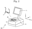
- Fig. 2 is an appearance schematic view of an eyeglasses frame shape measurement device.
- the left and right direction thereof is represented as the X-direction, the up and down direction as the Y-direction, and the front and rear direction as the Z-direction. That is, the left and right direction (horizontal direction) of the eyeglasses frame shape measurement device is the X-direction, the up and down direction (vertical direction) is the Z-direction, and the front and rear direction (depth direction) is the Y-direction.
- the eyeglasses frame shape measurement device 100 includes an opening window 10, a monitor (display) 11, a switch unit 12, a frame holding portion 20, a frame measurement portion 60 (see Fig. 2 ), and the like.
- the switch unit 12 is used when inputting a signal for causing the eyeglasses frame shape measurement device 100 to execute various processing.
- the various processes are the start of measurement and the like.
- the switch unit 12 is provided on a main body cover of the eyeglasses frame shape measurement device 100.
- the switch unit 12 may be displayed electronically on a screen of the monitor 11.
- the frame holding portion 20 is disposed inside the opening window 10.
- the frame holding portion 20 holds the frame F in a desired state by abutting on the outer edge of the rim in the frame F.
- the frame holding portion 20 may be configured to be able to hold at least one of a full rim frame and the like in which a bevel of a lens LE is fitted around the entire circumference of the rim of the frame F, an under rim frame in which the bevel of the lens LE is fitted into at least the lower end of the rim of the frame F, and the like. That is, it may be configured to be able to hold a frame having the rim of the frame F at least at a lower edge.
- a configuration in which the frame holding portion 20 holds the full rim frame is exemplified.
- Figs. 3 and 4 are views for describing the frame holding portion 20.
- Fig. 3 is a top view of the frame holding portion 20.
- Fig. 4 is a perspective view of the frame holding portion 20.
- illustration of the frame F held by the frame holding portion 20 is omitted.
- the frame holding portion 20 includes a holder base 21, a first slider 22, a second slider 23, an opening and closing movement mechanism 30, a clamp mechanism 40, and the like.
- the first slider 22 and the second slider 23 are placed on the holder base 21.
- the first slider 22 has a first surface 22a that abuts on the upper edges of a left rim FRL and a right rim FRR of the frame F.
- the second slider 23 has a second surface 23a that abuts on the lower edges of the right rim FRR and the left rim FRL of the frame F.
- the first surface 22a and the second surface 23a face each other.
- the first surface 22a and the second surface 23a are moved by the opening and closing movement mechanism 30 in a direction in which spacing between the first surface 22a and the second surface 23a is opened or closed (a direction in which spacing widens and the direction in which spacing narrows).
- clamp pins provided in the clamp mechanism 40 are disposed to protrude on the first surface 22a and the second surface 23a.
- the clamp pins clamp (hold) the left and right rims from the front and rear direction of the rims (front and rear sides in the eyeglasses wearing state).
- the first slider 22 is provided with a pair of clamp pins 24a and 24b as clamp pins.
- the clamp pin 24a and the clamp pin 24b are disposed at two positions and clamp the upper edges of the left rim FRL and the right rim FRR.
- the second slider 23 is provided with a pair of clamp pins 24c and 24d as clamp pins.
- the clamp pin 24c and the clamp pin 24d are disposed at two positions and clamp the lower edges of the left rim FRL and the right rim FRR.
- an abutment portion 25 which is a part of the second surface 23a may be provided between the clamp pin 24c and the clamp pin 24d.
- the lowermost edge of the rim of the frame F may be clamped with the clamp pin 24c and the clamp pin 24d. Since the clamp pin 24c and the clamp pin 24d protrude from a hole 26 (see Fig. 5 ) provided on the second surface 23a, in such a case, when the frame F is held by the first slider 22 and the second slider 23, the lowermost edge of the rim of the frame F enters the depth side of the second surface 23a.
- the abutment portion 25 is provided to prevent the lower edge of the rim of the frame F from entering the depth side of the second surface 23a.
- the opening and closing movement mechanism 30 includes two guide rails 31, a pulley 32, a pulley 33, a wire 34, a spring 35, and the like.
- the guide rails 31 are disposed on the left and right of the holder base 21 and extend in the Y-direction.
- the wire 34 is wound around the pulley 32 and the pulley 33.
- the right end portion 22R of the first slider 22 is attached to the left side of the wire 34.
- the right end portion 23R of the second slider 23 is attached to the right side of the wire 34.
- the spring 35 always biases spacing between the first slider 22 and the second slider 23 in the closing direction.
- the opening and closing movement mechanism 30 moves the first slider 22 and the second slider 23 in the direction in which the spacing is widened and the spacing is narrowed, with the center line N1 in the X-direction (see Fig. 3 ) as a center. That is, the first slider 22 and the second slider 23 are moved in the horizontal direction.
- the second slider 23 also moves by being interlocked.
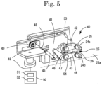
- Fig. 5 is schematic configuration view of the clamp mechanism 40.
- Fig. 4 illustrates the clamp mechanism 40 disposed on the left side of the second slider 23.
- the clamp mechanism includes a base plate 41, the clamp pin 24a, the clamp pin 24b, a first arm 42, a second arm 43, a compression spring 44, a spring 45, a gear 46, a gear 47, a wire 48, a pulley 49, a drive unit 240, and the like.
- the base plate 41 is disposed inside the first slider 22.
- the first arm 42 is rotatably held relative to the base plate 41 by the rotation shaft 53.
- the gear 46 centered on the rotation shaft 53 is formed on the first arm 42.
- the second arm 43 is rotatably held relative to the base plate 41 by the rotation shaft 54.
- the gear 47 centered on the rotation shaft 54 is formed on the second arm 43.
- the gear 46 and the gear 47 mesh with each other.
- the clamp pin 24c is attached to the tip of the first arm 42.
- the clamp pin 24d is attached to the tip of the second arm 43.
- the compression spring 44 is provided between the first arm 42 and the second arm 43. Spacing between the clamp pin 24c and the clamp pin 24d is always biased by the compression spring 44 in the opening direction.
- One end of the spring 45 is attached to the rear end of the first arm 42.
- the wire 48 is fixed to the other end of the spring 45.
- the wire 48 is connected to the drive unit 240 via the pulley 49
- the drive unit 240 includes a shaft 51, a motor 52, and the like.
- the shaft 51 winds the wire 48.
- the motor 52 rotates the shaft 51.
- the first arm 42 rotates counterclockwise around the rotation shaft 53.
- the second arm 43 rotates clockwise around the rotation shaft 54. With this, the clamp pin 24c and the clamp pin 24d are interlocked and closed, and the lower edge of the left rim FRL is clamped.
- the clamp mechanism (that is, the clamp mechanism disposed on the right side of the second slider 23) for clamping the lower edge of the right rim FRR may have a configuration in which the clamp mechanism 40 is reversed to the left and right.as illustrated in Fig. 4 .
- the clamp mechanisms (that is, the clamp mechanisms disposed respectively on the left and right sides of the first slider 22) for clamping the upper edges of the right rim FRR and the left rim FRL may have a configuration in which the clamp mechanisms 40 disposed on the second slider 23 are vertically reversed.
- the motor 52 and the shaft 51 may be configured to be respectively disposed in the clamp mechanisms 40 provided at four positions, but may be configured to be commonly used in the clamp mechanisms 40 provided at four positions.
- the four clamp pins are configured to be simultaneously opened and closed.
- the frame measurement portion 60 is disposed below the frame holding portion 20.
- the frame measurement portion 60 detects the position of a groove bottom of the rim in the frame F.
- the frame measurement portion 60 detects the position of the groove bottom of the rim by inserting a measurement stylus 62 described later into the groove of the rim of the frame F and moving the measurement stylus 62 in contact with the groove bottom of the rim.
- the frame measurement portion 60 may detect the deepest position (that is, the position at which the coordinate in the Y-direction at the groove bottom of the rim detected by the measurement stylus 62 is the smallest) of the groove bottom of the rim.
- a shape of the groove of the rim may be measured based on the detected position of the groove bottom of the rim.
- the frame measurement portion 60 detects the position of the outer edge of the rim in the frame F.
- the frame measurement portion 60 may detect the lowest position of the outer edge of the rim (for example, the position at which the coordinate in the Y-direction at the outer edge of the rim is the smallest).
- the frame measurement portion 60 may detect the lowest position of the outer edge of the rim by bringing the measurement stylus 62 described later into contact with the abutment surface (that is, the second surface 23a) of the frame holding portion 20 abutting on the outer edge of the rim.
- Figs. 6A and 6B are views for describing the frame measurement portion 60.
- Fig. 6A is a schematic configuration view of a moving unit 70.
- Fig. 6B is a schematic configuration view of a measurement stylus holding portion 80.
- the frame measurement portion 60 includes a base portion 61, the measurement stylus 62, a measurement stylus shaft 63, the moving unit 70, the measurement stylus holding portion 80, and the like.
- the base portion 61 is a rectangular frame extended in the X-direction and the Y-direction, and is disposed below the frame holding portion 20.
- the measurement stylus 62 is inserted into the groove of the rim of the frame F.
- the measurement stylus 62 is in contact with the groove bottom of the frame F and the abutment surface (that is, the second surface 23a) between the frame holding portion 20 and the outer edge of the rim.
- the measurement stylus 62 is attached to the tip of the measurement stylus shaft 63.
- the moving unit 70 moves the measurement stylus holding portion 80 relative to the frame F.
- the measurement stylus holding portion 80 holds the measurement stylus 62 and the measurement stylus shaft 63.
- the moving unit 70 moves the measurement stylus holding portion 80 in the X-direction, the Y-direction, and the Z-direction.
- the moving unit 70 includes a Y moving unit 71, an X moving unit 72, a Z moving unit 73, a motor 74, a motor 75, a motor 76, and the like.
- the Y moving unit 71 moves the measurement stylus holding portion 80 in the Y-direction.
- the motor 74 By driving of the motor 74, the Y moving unit 71 moves the measurement stylus holding portion 80 in the Y-direction, along a guide rail (not illustrated) extending in the Y-direction.
- the X moving unit 72 moves the Y moving unit 71 in the X-direction.
- the X moving unit 72 moves the Y moving unit 71 in the X-direction along the guide rail 77 extending in the X-direction by the drive of the motor 76.
- the Z moving unit 73 moves the measurement stylus holding portion 80 in the Z-direction.
- the Z moving unit 73 is attached to the Y moving unit 71, and moves the measurement stylus holding portion 80 in the Z-direction along the guide rail 78 extending in the Z-direction, by driving of the motor 75.
- the measurement stylus holding portion 80 includes a rotation unit 81 that rotates the measurement stylus shaft 63 around a rotation axis N2 extending in the Z-direction.
- the rotation unit 81 includes a rotation base 82 to which the measurement stylus shaft 63 is attached, and a motor 83 for rotating the rotation base 82 about the rotation axis N2.
- the rotation base 82 holds the measurement stylus shaft 63 so as to be movable (tiltable) in the direction of the tip of the measurement stylus 62.
- the rotation base 82 holds the measurement stylus shaft 63 so as to be movable in the Z-direction.
- the position of the measurement stylus 62 in the tip direction and the central position of the measurement stylus shaft 63 are detected by an encoder 84 which is a detector.
- the position of the measurement stylus 62 in the Z-direction and the position of the measurement stylus shaft 63 in the Z-direction are detected by an encoder 85 which is a detector.
- the measurement stylus holding portion 80 includes a measurement pressure application mechanism (not illustrated) for applying measurement pressure to press the tip of the measurement stylus 62 against the grooves of the rims (right rim FRR and left rim FRL) and the abutment surface (second surface 23a).
- the frame measurement portion 60 may serve as a measurement portion for detecting the position of the groove bottom of the rim and measuring the shape of the groove of the rim and a measurement portion for measuring a shape of a peripheral edge of a demo lens or a template.
- the frame measurement portion 60 can measure the shape of the peripheral edge of the demo lens or the template by detecting movement of the measurement stylus shaft 63 by bringing the measurement stylus shaft 63 into contact with the peripheral edge of the demo lens or the template.
- JP-A-2001-122899 and JP-A-2013-068439 see, for example, JP-A-2001-122899 and JP-A-2013-068439 , and the like.
- Fig. 7 is a view illustrating a control system of the eyeglasses frame shape measurement device 100.
- the control portion 90 is electrically connected to the monitor 11, the switch unit 12, a non-volatile memory 91 (hereinafter, the memory 91), the encoders (encoders 84 and 85), and the motors (motors 52, 74, 75, 76, and 83).
- the memory 91 may be a non-transitory storage medium capable of holding stored contents even when the supply of power is shut off.
- a hard disk drive, a flash ROM, a removable USB memory, or the like can be used.
- the memory 91 may store the position of the groove bottom of the rim in the frame F, the shape of the groove, the position of the outer edge of the rim, and the like measured by the frame measurement portion 60.
- control portion 90 is realized by a general CPU (processor), a RAM, a ROM, and the like.
- the CPU controls driving of each portion in the eyeglasses frame shape measurement device 100.
- the RAM temporarily stores various information.
- the ROM stores various programs executed by the CPU.
- the control portion 90 may be constituted by a plurality of control portions (namely, a plurality of processors).
- Fig. 9 is a schematic configuration view of the inside of the storage portion 204.
- the storage portion 204 includes a frame support portion 210, a lens measurement portion 220, a drive unit 240, and the like.
- the frame support portion 210 supports the frame F with the lower edge sides of the rims (left rim FRL and right rim FRR) in the frame F directed upward.
- the frame support portion 210 may be configured to support the frame F with the upper edge sides of the rims in the frame F directed upward.
- the frame support portion 210 includes a base 211, and a front support portion 212 and a rear support portion 213 provided on the base 211.
- the front support portion 212 has a "U"-shape opening upward.
- the front support portion 212 supports a bridge FB in the frame F.
- the bridge FB is supported by mounting the frame F on the front support portion 212 with the upper edge side of the rim directed downward.
- the bridge FB may be configured to be supported by mounting the frame F on the front support portion 212 with the lower edge side of the rim directed downward.
- the rear support portion 213 has a "U"-shape opening upward.
- the rear support portion 213 supports temple tips (left temple tip FML and right temple tip FMR) in the frame F.
- the frame F is mounted on the rear support portion 213 with the upper edge side of the rim directed downward, thereby supporting the temple tips.
- the frame F may be mounted on the rear support portion 213 with the lower edge side of the rim directed downward, thereby supporting the temple tips.
- the lens measurement portion 220 measures the optical characteristics of the lens LE in the eyeglasses (hereinafter, referred to as eyeglasses) in a framed state in which the lens LE is mounted in the frame F.
- the optical characteristics of the lens LE may be at least one of a spherical power S, a cylindrical power C, an astigmatic axis angle A, and a prism amount ⁇ .
- the lens measurement portion 220 also measures the length from an optical center position OC in the lens LE of the eyeglasses to a predetermined position.
- the predetermined position may be the length to the lower edge of the rim in the frame F of the eyeglasses, and the like.
- the lens measurement portion 220 includes abutment pins 221, a measurement optical system 230, and the like.
- the abutment pins 221 are fixed to the upper surface of an index plate 233 described later.
- the abutment pin 221 abuts on the rear surface of the lens LE.
- the abutment pins 221 are constituted by three pins, and are respectively disposed so as to be equidistant and equiangular to an optical axis L1 of the measurement optical system 230. That is, the abutment pins 221 are disposed such that the distances from a base point to the abutment pins 221 are equal, by using a point at which the optical axis L1 passes through the index plate 233 as the base point. Further, the abutment pins 221 are disposed such that angles formed by two straight lines connecting the base point and each abutment pins 221 are equal (that is, 120 degrees).
- the light source 231 includes a first light source 231a and a second light source 231b.
- the first light source 231a may be any light source that can emit a measurement light flux having a wavelength different from that of the second light source 231b.
- the first light source 231a may be a light source that can emit a measurement light beam different from that of the second light source 231b in at least one of a peak of the wavelength and a wavelength band.
- a light source emitting infrared light is used as the first light source 231a
- a light source emitting visible light is used as the second light source 231b.
- a measurement index for measuring the optical characteristics of the lens LE is formed on the index plate 233.
- a portion of the measurement index formed on the index plate 233 allows both the measurement light flux emitted from the first light source 231a and the measurement light flux emitted from the second light source 231b to pass.
- the portion other than the measurement index in the index plate 233 shields the measurement light flux emitted from the first light source 231a, but allows the measurement light flux emitted from the second light source 231b to pass.
- the collimator lens 232 makes the measurement light flux emitted from the light source 231 parallel (including substantially parallel) to the optical axis L1.
- the screen 234 is provided at a position spaced apart from the index plate 233 by a predetermined distance.
- the screen 234 also projects an image of the measurement index formed on the index plate 233.
- the imaging element 236 may be configured by a charge coupled device (CCD) or a complementary metal oxide semiconductor (CMOS).
- CMOS complementary metal oxide semiconductor
- the half mirror 237 passes or reflects the measurement light beam emitted from the light source 231.
- the drive unit 240 moves the frame support portion 210 in the X-direction, the Y-direction, and the Z-direction with respect to the lens measurement portion 220.
- a nut portion 241 is fixed to the lower portion of the lens measurement portion 220, and a feed screw 242 extending in the X-direction is screwed into the nut portion 241. Both ends of the feed screw 242 are connected to a base 243 through bearings.
- a ball bush (not illustrated) is fixed to the lower portion of the lens measurement portion 220, and a shaft 244 extending in the X-direction penetrates the ball bush. Both ends of the shaft 244 are connected to the base 243.
- the motor 245 is attached to the lower surface of the base 243. The drive shaft of the motor 245 is screwed with the feed screw 242.
- the feed screw 242 is rotated.
- the base 243 moves in the left and right direction (X-direction) together with the feed screw 242.
- the shaft 244 slides in a ball bush (not illustrated).
- the frame support portion 210 moves in the left and right direction with respect to the lens measurement portion 220 by moving the base 243 in this manner.
- a bearing support member 246 is fixed to the upper surface of the base 243.
- the bearing support member 246 is configured by a front support member located forward of the upper surface of the base 243 and a rear support member located on rearward of upper surface of the base 243.
- the front support member is provided with a bearing, to which one end of a feed screw 247 extending in the Z-direction is connected.
- the rear support member is also provided with a bearing through which the other end of the feed screw 247 penetrates.
- the other end of the feed screw 247 is connected to a drive shaft of a motor (not illustrated) fixed to the rear support member.
- a ball bush support member 248 is fixed to the upper surface of the base 243.
- the ball bush support member 248 is provided with a ball bush, and a shaft 249 extending in the Z-direction penetrates the ball bush.
- a nut support member (not illustrated) and a shaft support member 251 are fixed to the lower surface of a base 250.
- the nut support member is provided with a nut portion, which is screwed with the feed screw 247.
- the shaft support member 251 is provided with a ball bush, and the shaft 249 penetrates the ball bush.
- the feed screw 247 is rotated.
- the nut portion of the nut support member is fed to the feed screw 247, and the base 250 to which the nut support member and the nut support member are fixed moves in the front and rear direction (Z-direction).
- the shaft support member 251 fixed to the base 250 slides on the shaft 249.
- the frame support portion 210 moves in the front and rear direction with respect to the lens measurement portion 220 by moving the base 250 in this manner.
- the base 252 includes a nut portion, and a feed screw (not illustrated) extending in the Y-direction is screwed into the nut portion.
- a feed screw (not illustrated) is connected to the base 250 through the bearing provided on the base 250.
- the other end of the feed screw (not illustrated) is connected to an attachment plate 253 through the bearing provided on the attachment plate 253.
- the base 25 includes a ball bush, and each of a shaft 254 and a shaft 255 extending in the Y-direction penetrates the ball bush.
- One end of the shaft 254 is connected to the base 250 through the ball bush provided on the base 250.
- the other end of the shaft 254 is connected to the attachment plate 256 through a ball bush provided on the attachment plate 256.
- one end of the shaft 255 is connected to the base 250 through the ball bush provided on the base 250.
- the other end of the shaft 255 is connected to a attachment plate 257 through a ball bush provided on the attachment plate 257.
- a motor 258 is fixed to the attachment plate 253.
- the drive shaft of the motor 258 is connected to a feed screw (not illustrated) screwed to the nut portion.
- the nut portion of the base 252 is fed to the feed screw, and the base 252 moves in the up and down direction (Y-direction).
- the ball bushes of the base 252 slide on the shaft 254 and the shaft 255, respectively.
- driving of the motor 258 is not transmitted to the base 250 by the bearing, and the base 250 and the base 243 do not move in the up and down direction (Y-direction).
- the frame support portion 210 moves in the up and down direction with respect to the lens measurement portion 220 by moving the base 252 in this manner.
- Fig. 11 is a diagram illustrating a control system in the eyeglasses measurement device 200.
- the control portion 260 is electrically connected to the monitor 202, the operation button 203, the light source 231, the imaging element 236, and motors (for example, the motor 245 and the motor 258) included in the drive unit 240.
- the memory 261 may be a non-transitory storage medium capable of holding stored contents even when the supply of power is shut off.
- a hard disk drive, a flash ROM, a removable USB memory, or the like can be used.
- the memory 261 may store the optical characteristics and the like of the lens LE measured by the lens measurement portion 220.
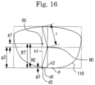
- such a layout may be at least one of a height H1 from a boxing center position BC of the target lens shape data to the optical center position OC, a height BT from a position P of the bottommost side of the target lens shape data to the optical center position OC, a height (in other words, PD height) H4 from the position of the bottom side directly below the optical center position in the target lens shape data to the optical center position OC, the boxing center-to-center distance FPD in the left and right lenses, the optical center-to-center distance PD in the left and right lenses (an interpupillary distance PD of the eyeglasses wearer), and the like.
- the operator machines the peripheral edge of the lens LE using the lens peripheral edge machining device.
- the operator acquires machining control data for forming a bevel on the periphery of the lens LE based on the target lens shape data and the layout data.
- machining control data based on lens surface shape data (for example, positions of the front surface and rear surface of the lens LE corresponding to target lens shape data, a curve value of the front surface of lens LE, and the like) of the lens LE, a processing condition of the lens LE, and the like may be acquired.
- the operator performs machining based on such machining control data on the lens LE to acquire the lens LE having the bevel LEb formed on the peripheral edge.
- the operator frames the lens LE having the bevel LEb formed on the peripheral edge in the groove Fg formed on the rim of the frame F, and assembles the eyeglasses.
- the control portion 90 measures the position of the contact position M as the lowest position Q of the lower edge of the left rim FRL.
- three-dimensional data of the position of the contact position M that is, three-dimensional data (xQ, yQ, zQ) of the lowest position Q of the lower edge of the left rim FRL
- three-dimensional data of the lowest position Q of the left rim FRL is represented by three-dimensional orthogonal coordinates.
- the control portion of the lens edge processing device acquires bevel formation data for forming the bevel LEb on the lens LE based on the lens shape data, the layout data, the machining condition, the lens surface shape data, and the like, and acquires machining control data for machining the peripheral edge of the lens LE based on the bevel formation data.
- the control portion of the lens peripheral edge machining device moves the lens chuck shaft based on the machining control data and adjusts a relative positional relationship of the lens LE with respect to a grindstone. With this, the operator can process the peripheral edge of the lens LE and form the bevel LEb on the peripheral edge of the lens LE.
- the operator assembles the eyeglasses by framing the lens LE having the bevel LEb formed on the peripheral edge thereof in the groove Fg formed on the rim of the frame F.
- the operator uses the eyeglasses measurement device 200 to acquire the height from the outer edge of the rim to the optical center position OC of the lens LE. That is, for the eyeglasses with the lens LE mounted in the frame F, the height from the outer edge of the rim to the optical center position OC of the lens LE is acquired.
- the height from the outer edge of the rim to the optical center position OC of the lens LE may be a height H3 from the lowest position edge (that is, the lowest position Q) of the outer edge of the rim to the optical center position OC.
- the height from the outer edge of the rim to the optical center position OC of the lens LE may be a height H4 from the outer edge of the rim directly below the optical center position to the optical center position OC.
- a case where the lens measurement portion 220 acquires the height H3 from the lowest position Q of the outer edge of the left rim FRL of the frame F to the optical center position OC of the lens LE as a height from the outer edge of the rim to the position OC of the lens LE is taken as an example.
- the operator places the eyeglasses on the front support portion 212 and the rear support portion 213 and causes the frame support portion 210 to support the eyeglasses. Subsequently, the operator operates the operation button 203 displayed on the monitor 202 to start measurement of the height H3 from the lowest position Q of the outer edge of the left rim FRL of the frame F to the optical center position OC of the lens LE.
- the control portion 260 controls driving of the drive unit 240 to move the position of the frame support portion 210 relative to the lens measurement portion 220 from the initial position to the measurement position.
- the initial position of the frame support portion 210 in the X-directions and Y-directions is set to a position where the center between upper and lower portion of the front support portion 212 and the center between upper and lower abutment pins 221 (that is, the optical axis L1 of the measurement optical system 230) coincide with each other.
- the initial position of the frame support portion 210 in the Z-direction is set to a position separated from the abutment pins 221 by a predetermined distance.
- the predetermined distance may be a distance such that the lens LE of the eyeglasses placed on the frame support portion 210 and the abutment pin 221 do not contact each other.
- the initial position may be set to any position.
- the control portion 260 drives the motors of the drive unit 240 to move the frame support portion 210 from the initial position in the X, Y, and Z-directions, respectively, and brings the abutment pins 221 into contact with the lens LE framed in the left rim FRL.
- the control portion 260 may receive layout data from the server to determine an approximate movement amount of the frame support portion 210 with respect to the lens measurement portion 220. With this, the optical axis L1 of the measurement optical system 230 is aligned near the optical center position of the lens LE framed in the left rim FRL.
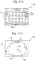
- Figs. 14A and 14B are examples of a captured image 270 captured by the imaging element 236.
- Fig. 14A is a captured image 270a in a state in which the first light source 231a is turned on.
- Fig. 14B is a captured image 270b in a state in which the second light source 231b is turned on.
- the control portion 260 turns on the first light source 231a and irradiates the lens LE with the measurement light flux that has passed through only the portion of the measurement index in the index plate 233.
- the control portion 260 captures an image (frame image Fp) of the frame F projected on the screen 234, an image of the lens LE (lens image LEp), and images (visual target light flux images 231p) of the visual target light flux which has passed through the lens LE by the imaging element 236. With this, the captured image 270a is acquired.
- the control portion 260 performs image processing on the captured image (that is, the reference image) in a state in which the eyeglasses are not placed on the frame support portion 210 and the captured image 270 in a state in which the eyeglasses are placed on the frame support portion 210 to analyze where in the captured image 270a each visual target luminous flux image 231p in the reference image has moved.
- the control portion 260 obtains an optical center position OCp in the lens image LEp based on the movement position of each visual target light flux image 231p.
- the pixel position (that is, the position coordinate) of the optical center position OCp in the lens image LEp on the captured image 270 is stored in the memory 261.
- the control portion 260 turns on the second light source 231b, and irradiates the lens LE with the measurement light flux that has passed both a portion of the measurement index part in the index plate 233 and a portion other than the measurement index.
- the captured image 270b obtained by capturing the frame image Fp and the lens image LEp is acquired.
- the control portion 260 performs image processing on the captured image 270b to acquire the height H3p from the lowest position Qp of the outer edge in the image (left rim image FRLp) of the left rim FRL to the optical center position OCp in the lens image LEp.
- control portion 260 performs edge detection on the captured image 270b and detects the rise and fall of luminance in the captured image 270b, thereby detecting the lowest position Qp of the outer edge in the left rim image FRLp.
- control portion 260 stores the pixel position (position coordinate) of the position Qp on the captured image 270 in the memory 261.
- the control portion 260 obtains the height H3p from the lowest position Qp of the outer edge in the left rim image FRLp to the optical center position OCp in the lens image Lep, based on the pixel position of the optical center position OCp in the lens image LEp and the pixel position of the lowest position Qp of the outer edge in the left rim image FRLp stored in the memory 261. Since such a height H3p is represented by the number of pixels in the captured image 270b, the height H3p may be converted to an actual height H3. For example, the actual distance corresponding to one pixel of the captured image 270 may be set in advance by experiment, simulation, or the like. With this, the control portion 260 can acquire the height H3 from the lowest position Q of the outer edge in the left rim FRL to the optical center position OC of the lens LE in the eyeglasses placed on the frame support portion 210.
- the operator acquires the height from the groove bottom of the rim to the optical center position OC of the lens LE based on the first information and the second information. For example, in this example, based on the thickness T (first information) of the left rim FRL in the depth direction of the groove FG and the height H3 (second information) from the lowest position Q of the outer edge in the left rim FRL to the optical center position OC of the lens LE, the height BT (that is, a distance BT vertically connecting the deepest position P of the groove bottom of the rim and the optical center position OC) from the deepest position P of the groove bottom of the left rim FRL to the optical center position OC of the lens LE is acquired.
- the height BT that is, a distance BT vertically connecting the deepest position P of the groove bottom of the rim and the optical center position OC
- the control portion 260 of the eyeglasses measurement device 200 can calculate the difference between the height H3 from the lowest position Q of the outer edge in the left rim FRL to the optical center position OC of the lens LE and the thickness T of the left rim FRL in the depth direction of the groove FG to obtain the height BT (third information) from the deepest position P of the groove bottom of the left rim FRL to the optical center position OC of the lens LE. For example, in this example, such a height BT is displayed on the monitor 202.
- the thickness T of the rim in the depth direction of the groove FG, the height H3 from the lowest position Q of the outer edge of the rim to the optical center position OC, and the like may be displayed on the monitor 202.
- Such information may be output by display on a tablet terminal or the like, printing using a printer or the like, storage in an external memory (for example, a USB memory or the like), or the like.
- the control portion 260 of the eyeglasses measurement device 200 acquires comparison information obtained by comparing the acquired height BT (hereinafter, referred to as height BT') of the eyeglasses with the height BT from the position P of the bottommost side of the target lens shape data to the optical center position OC, in which the height BT is set when the lens is machined.
- the comparison information may be information in which values of the height BT' of the eyeglasses and the height BT which is set when the lens is machined are arranged.
- the comparison information may be output by display, printing, storage, and the like. Also, for example, the comparison information may be used to determine the quality of the third information.
- control portion 260 of the eyeglasses measurement device 200 determines quality of the acquired height BT' of the eyeglasses based on the height BT from the position P of the bottom of the lens shape data to the optical center position OC, the height BT is set when the lens is machined.
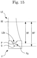
- Fig. 15 is a view illustrating the eyeglasses in a state where there is a gap between the groove Fg of the frame F and the bevel LEb of the lens LE.
- the control portion 260 receives the layout data which is set when the lens LE is machined and detects the amount of deviation between the height BT which is set when the lens is machined and the measured height BT'. In this case, it is determined whether the amount of deviation between the height BT set for the left rim FRL and the height BT' measured at the left rim FRL is within an error range.
- the error range may be set to the height BT ⁇ 0.1 mm or the like in advance.
- the control portion 260 determines that the height BT' (that is, third information) is good. When the amount of deviation between the height BT and the height BT' exceeds the error range, the control portion 260 also determines that the height BT' is not good. Similarly to the left rim FRL, for the right rim FRR, the quality of height BT' is also determined based on the amount of deviation between the height BT set for the right rim FRR and the height BT' measured at the right rim FRR.
- the control portion 260 detects the amount of deviation between the height BT' measured at the left rim FRL and the height BT' measured at the right rim FRR. In this case, it is determined whether the amount of deviation between the height BT' measured at the left rim FRL and the height BT' measured at the right rim FRR is within an error range.
- the error range may be set to within 0.1 mm or the like in advance.
- the control portion 260 determines that the height BT' of the eyeglasses is good. Further, when the deviation amount between the height BT' of the left rim FRL and the height BT' of the right rim FRR exceeds the error range, the control portion 260 determines that the height BT' of the eyeglasses is not good.
- the determination result of the quality of the height BT' of such eyeglasses is displayed on the monitor 202.
- the calculated amount of deviation may be displayed on the monitor 202, or a determination index (for example, A determination if within the error range, B determination if outside the error range, and the like) may be displayed on the monitor 202.
- a determination index for example, A determination if within the error range, B determination if outside the error range, and the like
- such information may be output by display on a tablet terminal or the like, printing using a printer or the like, storage in an external memory (for example, a USB memory or the like), or the like. The operator can easily determine, by confirming the output information, whether the eyeglasses can be manufactured as the layout.
- the eyeglasses measurement system in this example acquires the first information that indicates the thickness of the rim of the frame of the eyeglasses, in which the thickness is in the depth direction of the groove FG formed on the rim, acquires the second information which indicates the height from the position of the outer edge of the rim to the optical center position of the lens in a framed state in which the lens of the eyeglasses is mounted in the frame, and acquires the third information which indicates the height from the position of the groove bottom of the rim in the framed state to the optical center position based on the first information and the second information.
- the eyeglasses measurement system in this example detects the position of the groove bottom of the rim and the position of the outer edge of the rim and acquires the first information based on the position of the groove bottom of the rim and the position of the outer edge of the rim.
- frames are manufactured based on design data, but individual differences may occur even with the same frame.
- accurate first information can be acquired for each frame.
- the eyeglasses measurement system in this example detects the deepest position of the groove bottom of the rim in the frame and the lowest position of the outer edge at the outer edge of the rim, acquires the height from the deepest position of the groove bottom of the rim to the lowest position of the outer edge of the rim as the first information, acquires the height from the lowest position of the outer edge of the rim to the optical center position of the lens as the second information, and acquires the height from the deepest position of the groove bottom of the rim to the optical center position as third information based on the first information and the second information.
- the height that is, BT which is one of the eye point indices from the position where the bevel apex is the lowermost edge to the optical center position of the lens can be easily acquired.
- the frame holing portion abuts on the outer edge of the frame to hold the frame, and the measurement stylus contacts the groove bottom of the rim and the abutment surface of the frame holding portion abutting on the outer edge of the rim , thereby the first information is acquired based on the movement position of the measurement stylus.
- the shape for example, the three-dimensional shape of the groove of the rim of the frame
- machining control data for machining the lens is created using this shape data.
- the position of the bevel apex formed on the lens based on the shape data changes depending on the contact position of the measurement stylus.
- the measurement stylus contacting both the groove bottom of the rim and the abutment surface (that, the lowermost edge of the rim) abutting on the outer edge of the rim, the first information can be acquired with high accuracy without providing a configuration for considering an error from the position of the groove bottom of the rim to the contact position of the measurement stylus.
- the eyeglasses measurement system acquires the comparison information obtained by comparing the third information in the framed state of the eyeglasses with the height from the position of the groove bottom of the rim to the optical center position, in which the height is set when the lens is machined. Further, the quality of the third information of the eyeglasses is determined based on the height from the groove bottom of the rim to the optical center position, in which the height is set when the lens is machined. With this, the operator can easily compare and determine whether the layout of the eyeglasses is finished as planned, whether the layout of the eyeglasses is appropriate, and the like.
- a configuration in which, when three-dimensional data is acquired at the lowest position Q of the outer edge of the rim using the eyeglasses frame shape measurement device 100, the measurement stylus 62 is brought into direct contact with the second surface 23a of the second slider 23, is described by being taken as an example, but is not limited thereto.
- a configuration in which a patch plate is provided on the second surface 23a of the second slider 23 and the measurement stylus 62 is brought into contact with the backing plate may be adopted.
- the patch plate may be a metal plate.
- the second slider 23 is made of resin
- the measurement stylus 62 is made of metal.
- the contact position M of the second surface 23a may be gradually recessed because the resin is softer than metal. If the second surface 23a is recessed, accurate three-dimensional data cannot be obtained at the lowest position Q of the outer edge of the rim. For that reason, three-dimensional data may be acquired by providing the patch plate on the second surface 23a and bringing the measurement stylus 62 into contact with the patch plate.
- the patch plate may be provided on the entire surface of the second surface 23a, or may be provided so as to have a length at least as long as the left and right direction of the frame F at the second surface 23a.
- the patch plate may have a contact portion similarly to the second surface 23a.
- the eyeglasses frame shape measurement device 100 includes the frame holding portion 20 for holding the frame F in contact with the outer edge of the rim of the frame F and the measurement stylus 62 in contact with the groove bottom of the rim of the frame F and the abutment surface (in this example, the second surface 23a) between the frame holding portion 20 and the outer edge of the rim, and the thickness T (that is, the first information) of the rim in the depth direction of the groove FG is acquired based on the movement position of the measurement stylus 62 is described by being taken as an example, but is not limited thereto.
- the eyeglasses frame shape measurement device 100 may be configured to include the projection optical system emitting a measurement light flux from the light source toward the groove bottom of the rim of the frame F and the outer edge of the rim and the light receiving optical system receiving the reflected light flux, in which the measurement light flux is reflected by the groove bottom of the rim of the frame and the outer edge of the rim, by the light receiving element and acquire the thickness T of the rim in the depth direction of the groove FG based on the reflected light flux from the groove bottom of the rim and the reflected light flux from the outer edge of the rim.
- the thickness T of the rim in the depth direction of the groove FG may be obtained by detecting the position of the groove bottom of the rim and the position of the outer edge of the rim by image processing from a cross-sectional image obtained by imaging the cross-sectional shape of the groove of the rim.
- the eyeglasses measurement system in this example can accurately acquire the position (that is, the position of the bevel apex formed on the lens) of the groove bottom of the rim and the position of the outer edge of the rim, and can acquire the first information with high accuracy.
- the frame measurement portion 60 of the eyeglasses frame shape measurement device 100 measures three-dimensional data of the lowest position Q of the outer edge of the rim after measuring three-dimensional data of the deepest position P of the groove bottom of the rim is described by being taken as an example, but is not limited thereto.
- the frame measurement portion 60 may be configured to measure three-dimensional data of the deepest position P of the groove bottom of the rim after measuring three-dimensional data of the lowest position Q of the outer edge of the rim. That is, measurement of the deepest position of the groove bottom of the rim and the lowest position Q of the outer edge of the rim may be performed first.
- control portion 90 of the eyeglasses frame shape measurement device 100 transmits the thickness T of the rim in the depth direction of the groove FG acquired based on three-dimensional data of the deepest position P of the groove bottom of the rim and three-dimensional data of the lowest position Q of the outer edge of the rim to the server is described by being taken as an example, but is not limited thereto.
- the control portion 90 of the eyeglasses frame shape measurement device 100 may transmit the three-dimensional data of the deepest position P of the groove bottom of the rim and three-dimensional data of the lowest position Q of the outer edge of the rim to the server.
- the control portion of the server may acquire the thickness T of the rim in the depth direction of the groove FG based on three-dimensional data of the deepest position P of the groove bottom of the rim and three-dimensional data of the lowest position Q of the outer edge of the rim. That is, the control portion of the server may compute and acquire the thickness T of the rim in the depth direction of the groove FG.
- the frame support portion 210 of the eyeglasses measurement device 200 supports the frame F by the front support portion 212 and the rear support portion 213 is described by being taken as an example, but is not limited thereto.
- the frame support portion 210 may be configured to support the frame F such that the lower edge of the rim of the frame F abuts on the base 211.
- the frame support portion 210 may be configured to support the frame F by sandwiching the upper edge and the lower edge of the rim of the frame F. That is, for example, the frame support portion 210 may be configured to bring the lower edge of the rim of the frame F into contact with a horizontal reference surface which is a horizontal reference.
- a configuration in which the lens measurement portion 220 of the eyeglasses measurement device 200 detects the deepest position Qp of the outer edge in the left rim image FRLp from the captured image 270b and acquires the height H3p from the deepest position Qp of the outer edge to the optical center position OCp in the lens image LEp is described by being taken as an example, but is not limited thereto.
- a configuration in which, when the tilt is detected in the frame image Fp in the captured image 270b (that is, when the frame F is tilted with respect to the imaging surface of the imaging element 236), the tilt of the frame image Fp is corrected to obtain the height H3p from the deepest position Qp of the outer edge to the optical center position OCp in the lens image Lep may be adopted.
- the control portion 260 of the eyeglasses measurement device 200 may acquire target lens shape data from the eyeglasses frame shape measurement device 100 and compare the target lens shape data with the frame image Fp to determine the tilt of the frame image Fp. Further, the tilt of the frame image Fp may be corrected based on the target lens shape data.
- control portion 260 of the eyeglasses measurement device 200 performs quality determination based on the height BT (third information) is described by being taken as an example, but is not limited thereto.
- the control portion 260 may perform quality determination based on other information, in addition to the height BT.
- the control portion 260 may perform the quality determination for the optical center-to-center distance PD between the lens LE framed in the left rim FRL of the eyeglasses and the lens LE framed in the right rim FRR of the eyeglasses. In this case, it may be determined whether the amount of deviation between the optical center-to-center distance PD in the set layout data and the measured optical center-to-center distance PD is within an error range.
- control portion 260 may perform quality determination of the PD height H2 for each of the lens LE framed in the left rim FRL of the eyeglasses and the lens LE framed in the right rim FRR of the eyeglasses. In this case, it may be determined whether the amount of deviation between the PD height H2 in the set layout data and the measured PD height H2 is within an error range.
- the control portion 260 of the eyeglasses measurement device 200 compares the measured height BT' with the height BT which is set when the lens is machined and determines the quality
- the quality may be determined by comparing information of at least one of the measured PD height H2, the boxing center-to-center distance FPD, the optical center-to-center distance PD, and the like with the information which is set when the lens is machined. That is, the control portion 260 may determine the quality of the layout of the eyeglasses.
- the measured height BT' may be compared with the PD height H2 which is set when the lens is machined to determine the quality thereof.
- the control portion 260 of the eyeglasses measurement device 200 may convert the measured height BT' into the PD height H2.
- Fig. 16 is a view for describing conversion between the height BT and the PD height.
- the control portion 260 of the eyeglasses measurement device 200 obtains the position coordinates of the boxing center position BC of the target lens shape data 110 based on the target lens shape data 110 (that is, the shape data 110 of the groove bottom obtained by connecting three-dimensional data of the groove bottom of the rim) acquired by the eyeglasses frame shape measurement device 100.
- the boxing center position BC is an intersection point of straight lines connecting middle points of opposing sides in a quadrangle surrounding the target lens shape data 110.
- the position coordinates of the optical center position OC of the lens LE, the deepest position P of the groove bottom of the rim, and the like are obtained by measurement of the eyeglasses using the eyeglasses measurement device 200. For that reason, the control portion 260 can calculate a height g1 from the boxing center position BC to the optical center position OC by the position coordinates of the boxing center position BC and the position coordinates of the optical center position OC. The control portion 260 can also calculate a height g2 from the boxing center position BC to the position P by the position coordinates of the boxing center position BC and the position coordinates of the deepest position P of the groove bottom of the rim.
- the control portion 260 obtains position coordinates of an intersection point d1 of a straight line k1 extending in the vertical direction through the optical center position OC and the target lens shape data 110.
- the position coordinates of the intersection point d1 can be calculated based on the coordinate position for each radial angle r in the target lens shape data 110.
- the control portion 260 also obtains the position coordinates of an intersection point d2 of the straight line k1 extending in the vertical direction through the optical center position OC and the straight line k2 extending horizontally through the deepest position P of the groove bottom of the rim. With this, the control portion 260 can calculate a height g3 from the intersection point d1 to the intersection point d2.
- the control portion 260 of the eyeglasses measurement device 200 measures the optical center position of the lens mounted in the frame F and performs the quality determination based on the height BT (third information) is described by being taken as an example, but is not limited thereto.
- the control portion 260 may measure the optical characteristics of an eye point position of the wearer in the lens mounted in the frame F to determine the quality of the optical characteristics.
- the optical characteristic may be at least one of a spherical power, a cylindrical power, an astigmatic axis angle, a prism amount, and the like.
- a prism amount is measured as an optical characteristic and the quality thereof is determined is taken as an example.
- the eye point position of the wearer is a pupil position of the wearer
- layout information of the lens is set such that the eye point position coincides with the optical center position. For that reason, for example, in a case where a single focus lens is machined, layout information is set such that the prism amount at the eye point position (that is, the optical center position of the lens) becomes zero.
- the lens after machining is assembled to the frame F, if the eye point position does not coincide with the optical center position of the lens, a prism may be generated.
- the control portion 260 measures the optical characteristics of the eye point position based on the layout data (for example, the height BT and the optical center-to-center distance PD described above) which is set when the lens is machined, and acquires the prism amount thereof.
- the control portion 260 determines whether or not the acquired prism amount is zero.
- an allowable range of error may be provided for the prism amount.
- the allowable range may be set to within ⁇ 0.67 prism diopter or the like in advance.
- the control portion 260 determines that the amount of prisms is good. That is, it is determined that the eye point position and the optical center position coincide with (substantially coincide with) each other.
- the control portion 260 determines that the amount of prisms is not good. That is, it is determined that the eye point position and the optical center position do not coincide with each other.
- layout information is set so that a predetermined amount of prism is given to an eye point position when machining a lens of prism prescription. For that reason, for example, the control portion 260 may determine whether or not the prism amount at the eye point position based on the layout data which is set when the lens is machined coincides with a predetermined prism amount.
- the control portion of the lens peripheral edge machining device may obtain again machining control data in consideration of these amounts of deviation, and may perform lens machining based on the machining control data.
Landscapes
- Physics & Mathematics (AREA)
- General Physics & Mathematics (AREA)
- Eyeglasses (AREA)
- Grinding And Polishing Of Tertiary Curved Surfaces And Surfaces With Complex Shapes (AREA)
Claims (10)
- Brillenmesssystem (1) zum Messen einer Brille, umfassend:einen ersten Erfassungsabschnitt (90), der konfiguriert ist, um erste Informationen zu erfassen, die eine Dicke eines Rands (FRR, FRL) eines Rahmens (F) der Brille angeben, wobei die Dicke in einer Tiefenrichtung einer auf dem Rand (FRR, FRL) ausgebildeten Nut (FG) ist;einen zweiten Erfassungsabschnitt (260), der konfiguriert ist, um zweite Informationen zu erfassen, die eine Höhe von einer Position einer Außenkante des Rands (FRR, FRL) zu einer optischen Mittenposition (OC) einer Linse (LE) der Brille in einem gerahmten Zustand angeben, in dem die Linse (LE) in dem Rahmen (F) montiert ist; undeinen dritten Erfassungsabschnitt (260), der konfiguriert ist, um dritte Informationen zu berechnen, die eine Höhe von einer Position eines Nutbodens (FG) des Rands (FRR, FRL) zu der optischen Mittenposition (OC) in dem gerahmten Zustand angeben, basierend auf den durch den ersten Erfassungsabschnitt (90) erfassten ersten Informationen und den durch den zweiten Erfassungsabschnitt (260) erfassten zweiten Informationen.
- Brillenmesssystem (1) nach Anspruch 1, ferner umfassend:einen Nutbodendetektionsabschnitt (FG), der konfiguriert ist, um die Position des Nutbodens (FG) des Rands (FRR, FRL) zu detektieren; undeinen Außenkantendetektionsabschnitt, der konfiguriert ist, um die Position der Außenkante des Rands (FRR, FRL) zu detektieren,wobei der erste Erfassungsabschnitt (90) konfiguriert ist, um die ersten Informationen basierend auf der durch den Nutbodendetektionsabschnitt (FG) detektierten Position des Nutbodens (FG) und der durch den Außenkantendetektionsabschnitt detektierten Position der Außenkante zu erfassen.
- Brillenmesssystem (1) nach Anspruch 2,wobei der Rahmen (F) den Rand (FRR, FRL) zumindest an einer Unterkante des Rahmens (F) beinhaltet,der Nutbodendetektionsabschnitt (FG) konfiguriert ist, um eine tiefste Position (P) des Nutbodens (FG) als die Position des Nutbodens (FG) zu detektieren,der Außenkantendetektionsabschnitt konfiguriert ist, um eine tiefste Position (Q) der Außenkante als die Position der Außenkante zu detektieren,der erste Erfassungsabschnitt (90) konfiguriert ist, um eine Höhe von der tiefsten Position (P) des Nutbodens (FG) zu der tiefsten Position (Q) der Außenkante als die ersten Informationen zu erfassen,der zweite Erfassungsabschnitt (260) konfiguriert ist, um eine Höhe von der tiefsten Position der Außenkante zu der optischen Mittenposition (OC) als die zweiten Informationen zu erfassen, undder dritte Erfassungsabschnitt (260) konfiguriert ist, um eine Höhe von der tiefsten Position des Nutbodens (FG) zu der optischen Mittenposition (OC) als die dritten Informationen basierend auf den ersten Informationen und den zweiten Informationen zu berechnen.
- Brillenmesssystem (1) nach Anspruch 1 oder 3,
wobei die dritten Informationen mindestens eine von einer BT-Höhe, die eine Höhe von der tiefsten Position des Nutbodens (FG) des Rands (FRR, FRL) zu der optischen Mittenposition (OC) der Linse (LE) ist, und einer PD-Höhe, die eine Höhe von der Position des Nutbodens (FG) des Rands (FRR, FRL) direkt unter der optischen Mittenposition (OC) der Linse (LE) zu der optischen Mittenposition (OC) ist, sind, wobei die BT-Höhe und die PD-Höhe Indizes sind, die eine Augenpunkthöhe für die Brille angeben. - Brillenmesssystem (1) nach Anspruch 2 oder 3, ferner umfassend:einen Rahmenhalteabschnitt (F), der an der Außenkante des Rands (FRR, FRL) anliegt, um den Rahmen (F) zu halten; undeinen Messstift, der den Nutboden (FG) des Rands (FRR, FRL) und eine Anlagefläche des Rahmenhalteabschnitts (F), die an der Außenkante des Rands (FRR, FRL) anliegt, berührt,wobei der erste Erfassungsabschnitt (90) konfiguriert ist, um die ersten Informationen basierend auf einer Bewegungsposition des Messstifts zu erfassen.
- Brillenmesssystem (1) nach Anspruch 2 oder 3, ferner umfassend:ein optisches Projektionssystem, das konfiguriert ist, um einen Messlichtfluss von einer Lichtquelle zu dem Nutboden (FG) und der Außenkante des Rands (FRR, FRL) zu emittieren; undein optisches Lichtempfangssystem, in dem ein Lichtempfangselement konfiguriert ist, um einen reflektierten Lichtfluss zu empfangen, der durch Reflektieren des Messlichtflusses durch den Nutboden (FG) und die Außenkante erhalten wird,wobei der erste Erfassungsabschnitt (90) konfiguriert ist, um die ersten Informationen basierend auf dem reflektierten Lichtfluss von dem Nutboden (FG) und dem reflektierten Lichtfluss von der Außenkante zu erfassen.
- Brillenmesssystem (1) nach einem der Ansprüche 1 bis 6, ferner umfassend:
einen Vergleichsinformationserfassungsabschnitt, der konfiguriert ist, um Vergleichsinformationen zu erfassen, die durch Vergleichen der dritten Informationen in dem gerahmten Zustand der Brille mit einer Höhe von der Position des Nutbodens (FG) des Rands (FRR, FRL) zu der optischen Mittenposition (OC) erhalten werden, wobei die Höhe eingestellt wird, wenn die Linse (LE) bearbeitet wird. - Brillenmesssystem (1) nach Anspruch 7, ferner umfassend:
einen Bestimmungsabschnitt, der konfiguriert ist, um die Qualität der dritten Informationen in dem gerahmten Zustand der Brille basierend auf der Höhe von der Position des Nutbodens (FG) des Rands (FRR, FRL) zu der optischen Mittenposition (OC) zu bestimmen, wobei die Höhe eingestellt wird, wenn die Linse (LE) bearbeitet wird. - Brillenmessverfahren, das in einem Brillenmesssystem (1) zum Messen einer Brille verwendet wird,
wobei das Brillenmessverfahren, das von einem Prozessor in dem Brillenmesssystem (1), das eine Brille misst, ausgeführt wird, umfasst:einen ersten Erfassungsschritt des Erfassens erster Informationen, die eine Dicke eines Rands (FRR, FRL) eines Rahmens (F) der Brille angeben, wobei die Dicke in einer Tiefenrichtung einer auf dem Rand (FRR, FRL) ausgebildeten Nut (FG) ist;einen zweiten Erfassungsschritt des Erfassens zweiter Informationen, die eine Höhe von einer Position einer Außenkante des Rands (FRR, FRL) zu einer optischen Mittenposition (OC) einer Linse (LE) der Brille in einem gerahmten Zustand angeben, in dem die Linse (LE) in dem Rahmen (F) montiert ist; undeinen dritten Erfassungsschritt des Berechnens dritter Informationen, die eine Höhe von der Position des Nutbodens (FG) des Rands (FRR, FRL) zu der optischen Mittenposition (OC) in dem gerahmten Zustand angeben, basierend auf den in dem ersten Erfassungsschritt erfassten ersten Informationen und den in dem zweiten Erfassungsschritt erfassten zweiten Informationen. - Brillenmessprogramm, umfassend Anweisungen, um die Vorrichtung nach den Ansprüchen 1 bis 8 zu veranlassen, die Schritte des Verfahrens nach Anspruch 9 auszuführen, wobei das Brillenmessprogramm von einem Prozessor in dem Brillenmesssystem (1) ausgeführt wird.
Applications Claiming Priority (1)
| Application Number | Priority Date | Filing Date | Title |
|---|---|---|---|
| JP2018126313A JP7143652B2 (ja) | 2018-07-02 | 2018-07-02 | 眼鏡測定システム及び眼鏡測定プログラム |
Publications (2)
| Publication Number | Publication Date |
|---|---|
| EP3591334A1 EP3591334A1 (de) | 2020-01-08 |
| EP3591334B1 true EP3591334B1 (de) | 2025-04-23 |
Family
ID=67137802
Family Applications (1)
| Application Number | Title | Priority Date | Filing Date |
|---|---|---|---|
| EP19183566.9A Active EP3591334B1 (de) | 2018-07-02 | 2019-07-01 | Brillenmesssystem, brillenmessverfahren und brillenmessprogramm |
Country Status (2)
| Country | Link |
|---|---|
| EP (1) | EP3591334B1 (de) |
| JP (1) | JP7143652B2 (de) |
Families Citing this family (1)
| Publication number | Priority date | Publication date | Assignee | Title |
|---|---|---|---|---|
| CN115648064A (zh) * | 2022-09-16 | 2023-01-31 | 安徽巨目光学科技发展有限公司 | 一种镜片磨边机弯曲度扫描机构 |
Family Cites Families (17)
| Publication number | Priority date | Publication date | Assignee | Title |
|---|---|---|---|---|
| GB288585A (en) * | 1927-04-12 | 1929-02-21 | Lucien Mulot | Improvements relating to gauges |
| JPH05138518A (ja) * | 1991-11-13 | 1993-06-01 | Nikon Corp | レンズ周縁加工装置 |
| JP3547273B2 (ja) * | 1996-10-25 | 2004-07-28 | 株式会社ニデック | 眼鏡枠形状測定装置及び眼鏡枠形状測定方法 |
| JPH10166250A (ja) * | 1996-12-12 | 1998-06-23 | Topcon Corp | 眼鏡フレームの玉型形状測定装置 |
| JP2001122899A (ja) | 1998-11-10 | 2001-05-08 | Sumitomo Chem Co Ltd | メダカ由来のビテロジェニンおよび抗体 |
| JP2007216355A (ja) | 2006-02-17 | 2007-08-30 | Nidek Co Ltd | カップ取付け装置及び該装置にて使用するためのパターン板 |
| JP5202011B2 (ja) | 2007-02-28 | 2013-06-05 | 株式会社ニデック | レンズメータ |
| EP2027968B1 (de) * | 2007-12-28 | 2010-11-03 | Essilor International (Compagnie Generale D'optique) | Verfahren zur Bestimmung der Parameter für die Trägerherstellung einer Kontaktlinse |
| JP5209358B2 (ja) | 2008-03-31 | 2013-06-12 | 株式会社ニデック | ヤゲン軌跡設定方法及び眼鏡レンズ加工装置 |
| JP5204544B2 (ja) | 2008-05-07 | 2013-06-05 | 株式会社トプコン | レンズ保持治具装着装置 |
| JP5850310B2 (ja) | 2011-09-21 | 2016-02-03 | 株式会社ニデック | 眼鏡枠形状測定装置 |
| JP5919817B2 (ja) | 2011-12-27 | 2016-05-18 | 株式会社ニデック | レンズメータ |
| JP6338039B2 (ja) | 2012-03-09 | 2018-06-06 | 株式会社ニデック | カップ取り付けユニットを有する装置 |
| JP5983139B2 (ja) * | 2012-07-23 | 2016-08-31 | 株式会社ニデック | 眼鏡枠形状測定装置 |
| JP6515542B2 (ja) * | 2014-02-27 | 2019-05-22 | 株式会社ニデック | 眼鏡装用画像解析装置、眼鏡装用画像解析方法、及び眼鏡装用画像解析プログラム |
| JP6471588B2 (ja) * | 2015-03-31 | 2019-02-20 | 株式会社ニデック | 玉型形状決定装置、玉型形状決定方法及び玉型形状決定プログラム |
| JP7021468B2 (ja) | 2016-08-30 | 2022-02-17 | 株式会社ニデック | レンズ測定装置 |
-
2018
- 2018-07-02 JP JP2018126313A patent/JP7143652B2/ja active Active
-
2019
- 2019-07-01 EP EP19183566.9A patent/EP3591334B1/de active Active
Also Published As
| Publication number | Publication date |
|---|---|
| JP2020008601A (ja) | 2020-01-16 |
| JP7143652B2 (ja) | 2022-09-29 |
| EP3591334A1 (de) | 2020-01-08 |
Similar Documents
| Publication | Publication Date | Title |
|---|---|---|
| US11408798B2 (en) | Measuring individual data of spectacles | |
| EP2048472B1 (de) | Linsenform-messeinrichtung und verfahren, verfahren zum herstellen einer brillenlinse und verfahren zum herstellen von brillen | |
| CN105278124B (zh) | 限定用于对光学镜片进行修边的导向线的方法 | |
| US11635291B2 (en) | Workpiece holder for utilization in metrology system for measuring workpiece in different orientations | |
| CN102538707B (zh) | 一种对工件进行三维定位的装置及方法 | |
| JP2002139713A (ja) | 眼鏡レンズのレンズホルダ取付方法及び装置 | |
| EP3056888A1 (de) | Tragbare vorrichtung zur messung der fokalkraft einer linsenoberfläche | |
| JP7243237B2 (ja) | 眼鏡レンズ周縁加工情報取得装置及び眼鏡レンズ周縁加工情報取得プログラム | |
| EP3798566B1 (de) | Brillengestellformmessvorrichtung und brillenglasverarbeitungsvorrichtung | |
| EP3591334A1 (de) | Brillenmesssystem, brillenmessverfahren und brillenmessprogramm | |
| US9636795B2 (en) | Method of edging a spectacle lens, spectacle lens edging system and spectacle lens edging program | |
| EP3546121B1 (de) | Informationserfassungsvorrichtung, informationserfassungsverfahren und informationserfassungsprogramm | |
| JP2019060760A (ja) | レンズ特性測定装置及びレンズ特性測定装置の作動方法 | |
| JP7052567B2 (ja) | 眼鏡レンズ加工制御データ取得装置 | |
| CN205090947U (zh) | 用于采集光学镜片的图像的机器 | |
| JP7467896B2 (ja) | 眼鏡レンズ周縁加工用装置、眼鏡レンズ周縁加工用プログラム、及び、眼鏡レンズ加工方法 | |
| JP2007047131A (ja) | 非球面レンズの測定方法、非球面レンズの測定装置、非球面レンズの測定プログラム、非球面レンズの製造方法及び非球面レンズ | |
| JP2019098484A (ja) | 軸出し装置、レンズ加工用装置、眼鏡レンズ加工システム、及び眼鏡レンズ加工方法 | |
| KR20140012900A (ko) | 안경틀 형상 측정 장치 | |
| JP2021076659A (ja) | 眼鏡枠形状測定装置及び眼鏡枠形状測定プログラム | |
| JP7243706B2 (ja) | 玉型形状取得装置 | |
| JP2026062320A (ja) | リム位置取得プログラム、リム位置取得方法、および眼鏡枠形状測定装置 | |
| JP2012013538A (ja) | 測定装置 | |
| JP2012048004A (ja) | 眼鏡レンズ用加工装置 | |
| JP2577700B2 (ja) | レンズメーター |
Legal Events
| Date | Code | Title | Description |
|---|---|---|---|
| PUAI | Public reference made under article 153(3) epc to a published international application that has entered the european phase |
Free format text: ORIGINAL CODE: 0009012 |
|
| STAA | Information on the status of an ep patent application or granted ep patent |
Free format text: STATUS: THE APPLICATION HAS BEEN PUBLISHED |
|
| AK | Designated contracting states |
Kind code of ref document: A1 Designated state(s): AL AT BE BG CH CY CZ DE DK EE ES FI FR GB GR HR HU IE IS IT LI LT LU LV MC MK MT NL NO PL PT RO RS SE SI SK SM TR |
|
| AX | Request for extension of the european patent |
Extension state: BA ME |
|
| STAA | Information on the status of an ep patent application or granted ep patent |
Free format text: STATUS: REQUEST FOR EXAMINATION WAS MADE |
|
| 17P | Request for examination filed |
Effective date: 20200706 |
|
| RBV | Designated contracting states (corrected) |
Designated state(s): AL AT BE BG CH CY CZ DE DK EE ES FI FR GB GR HR HU IE IS IT LI LT LU LV MC MK MT NL NO PL PT RO RS SE SI SK SM TR |
|
| STAA | Information on the status of an ep patent application or granted ep patent |
Free format text: STATUS: EXAMINATION IS IN PROGRESS |
|
| 17Q | First examination report despatched |
Effective date: 20210708 |
|
| GRAP | Despatch of communication of intention to grant a patent |
Free format text: ORIGINAL CODE: EPIDOSNIGR1 |
|
| STAA | Information on the status of an ep patent application or granted ep patent |
Free format text: STATUS: GRANT OF PATENT IS INTENDED |
|
| GRAS | Grant fee paid |
Free format text: ORIGINAL CODE: EPIDOSNIGR3 |
|
| INTG | Intention to grant announced |
Effective date: 20250213 |
|
| RAP3 | Party data changed (applicant data changed or rights of an application transferred) |
Owner name: NIDEK CO., LTD. |
|
| RIN1 | Information on inventor provided before grant (corrected) |
Inventor name: TANAKA, MOTOSHI |
|
| GRAA | (expected) grant |
Free format text: ORIGINAL CODE: 0009210 |
|
| STAA | Information on the status of an ep patent application or granted ep patent |
Free format text: STATUS: THE PATENT HAS BEEN GRANTED |
|
| AK | Designated contracting states |
Kind code of ref document: B1 Designated state(s): AL AT BE BG CH CY CZ DE DK EE ES FI FR GB GR HR HU IE IS IT LI LT LU LV MC MK MT NL NO PL PT RO RS SE SI SK SM TR |
|
| REG | Reference to a national code |
Ref country code: GB Ref legal event code: FG4D |
|
| REG | Reference to a national code |
Ref country code: CH Ref legal event code: EP |
|
| REG | Reference to a national code |
Ref country code: DE Ref legal event code: R096 Ref document number: 602019068926 Country of ref document: DE |
|
| P01 | Opt-out of the competence of the unified patent court (upc) registered |
Free format text: CASE NUMBER: APP_17936/2025 Effective date: 20250414 |
|
| REG | Reference to a national code |
Ref country code: IE Ref legal event code: FG4D |
|
| PGFP | Annual fee paid to national office [announced via postgrant information from national office to epo] |
Ref country code: FR Payment date: 20250610 Year of fee payment: 7 |
|
| REG | Reference to a national code |
Ref country code: NL Ref legal event code: MP Effective date: 20250423 |
|
| PG25 | Lapsed in a contracting state [announced via postgrant information from national office to epo] |
Ref country code: NL Free format text: LAPSE BECAUSE OF FAILURE TO SUBMIT A TRANSLATION OF THE DESCRIPTION OR TO PAY THE FEE WITHIN THE PRESCRIBED TIME-LIMIT Effective date: 20250423 |
|
| REG | Reference to a national code |
Ref country code: AT Ref legal event code: MK05 Ref document number: 1788122 Country of ref document: AT Kind code of ref document: T Effective date: 20250423 |
|
| PG25 | Lapsed in a contracting state [announced via postgrant information from national office to epo] |
Ref country code: FI Free format text: LAPSE BECAUSE OF FAILURE TO SUBMIT A TRANSLATION OF THE DESCRIPTION OR TO PAY THE FEE WITHIN THE PRESCRIBED TIME-LIMIT Effective date: 20250423 Ref country code: PT Free format text: LAPSE BECAUSE OF FAILURE TO SUBMIT A TRANSLATION OF THE DESCRIPTION OR TO PAY THE FEE WITHIN THE PRESCRIBED TIME-LIMIT Effective date: 20250825 Ref country code: ES Free format text: LAPSE BECAUSE OF FAILURE TO SUBMIT A TRANSLATION OF THE DESCRIPTION OR TO PAY THE FEE WITHIN THE PRESCRIBED TIME-LIMIT Effective date: 20250423 |
|
| PGFP | Annual fee paid to national office [announced via postgrant information from national office to epo] |
Ref country code: DE Payment date: 20250528 Year of fee payment: 7 |
|
| REG | Reference to a national code |
Ref country code: LT Ref legal event code: MG9D |
|
| PG25 | Lapsed in a contracting state [announced via postgrant information from national office to epo] |
Ref country code: NO Free format text: LAPSE BECAUSE OF FAILURE TO SUBMIT A TRANSLATION OF THE DESCRIPTION OR TO PAY THE FEE WITHIN THE PRESCRIBED TIME-LIMIT Effective date: 20250723 Ref country code: GR Free format text: LAPSE BECAUSE OF FAILURE TO SUBMIT A TRANSLATION OF THE DESCRIPTION OR TO PAY THE FEE WITHIN THE PRESCRIBED TIME-LIMIT Effective date: 20250724 |
|
| PG25 | Lapsed in a contracting state [announced via postgrant information from national office to epo] |
Ref country code: PL Free format text: LAPSE BECAUSE OF FAILURE TO SUBMIT A TRANSLATION OF THE DESCRIPTION OR TO PAY THE FEE WITHIN THE PRESCRIBED TIME-LIMIT Effective date: 20250423 |
|
| PGFP | Annual fee paid to national office [announced via postgrant information from national office to epo] |
Ref country code: IT Payment date: 20250623 Year of fee payment: 7 |
|
| PG25 | Lapsed in a contracting state [announced via postgrant information from national office to epo] |
Ref country code: BG Free format text: LAPSE BECAUSE OF FAILURE TO SUBMIT A TRANSLATION OF THE DESCRIPTION OR TO PAY THE FEE WITHIN THE PRESCRIBED TIME-LIMIT Effective date: 20250423 |
|
| PG25 | Lapsed in a contracting state [announced via postgrant information from national office to epo] |
Ref country code: HR Free format text: LAPSE BECAUSE OF FAILURE TO SUBMIT A TRANSLATION OF THE DESCRIPTION OR TO PAY THE FEE WITHIN THE PRESCRIBED TIME-LIMIT Effective date: 20250423 |
|
| PG25 | Lapsed in a contracting state [announced via postgrant information from national office to epo] |
Ref country code: AT Free format text: LAPSE BECAUSE OF FAILURE TO SUBMIT A TRANSLATION OF THE DESCRIPTION OR TO PAY THE FEE WITHIN THE PRESCRIBED TIME-LIMIT Effective date: 20250423 |
|
| PG25 | Lapsed in a contracting state [announced via postgrant information from national office to epo] |
Ref country code: RS Free format text: LAPSE BECAUSE OF FAILURE TO SUBMIT A TRANSLATION OF THE DESCRIPTION OR TO PAY THE FEE WITHIN THE PRESCRIBED TIME-LIMIT Effective date: 20250723 |
|
| PG25 | Lapsed in a contracting state [announced via postgrant information from national office to epo] |
Ref country code: IS Free format text: LAPSE BECAUSE OF FAILURE TO SUBMIT A TRANSLATION OF THE DESCRIPTION OR TO PAY THE FEE WITHIN THE PRESCRIBED TIME-LIMIT Effective date: 20250823 |
|
| PG25 | Lapsed in a contracting state [announced via postgrant information from national office to epo] |
Ref country code: LV Free format text: LAPSE BECAUSE OF FAILURE TO SUBMIT A TRANSLATION OF THE DESCRIPTION OR TO PAY THE FEE WITHIN THE PRESCRIBED TIME-LIMIT Effective date: 20250423 |
|
| PG25 | Lapsed in a contracting state [announced via postgrant information from national office to epo] |
Ref country code: SM Free format text: LAPSE BECAUSE OF FAILURE TO SUBMIT A TRANSLATION OF THE DESCRIPTION OR TO PAY THE FEE WITHIN THE PRESCRIBED TIME-LIMIT Effective date: 20250423 Ref country code: DK Free format text: LAPSE BECAUSE OF FAILURE TO SUBMIT A TRANSLATION OF THE DESCRIPTION OR TO PAY THE FEE WITHIN THE PRESCRIBED TIME-LIMIT Effective date: 20250423 |
|
| PG25 | Lapsed in a contracting state [announced via postgrant information from national office to epo] |
Ref country code: CZ Free format text: LAPSE BECAUSE OF FAILURE TO SUBMIT A TRANSLATION OF THE DESCRIPTION OR TO PAY THE FEE WITHIN THE PRESCRIBED TIME-LIMIT Effective date: 20250423 |
|
| PG25 | Lapsed in a contracting state [announced via postgrant information from national office to epo] |
Ref country code: EE Free format text: LAPSE BECAUSE OF FAILURE TO SUBMIT A TRANSLATION OF THE DESCRIPTION OR TO PAY THE FEE WITHIN THE PRESCRIBED TIME-LIMIT Effective date: 20250423 |
|
| REG | Reference to a national code |
Ref country code: DE Ref legal event code: R097 Ref document number: 602019068926 Country of ref document: DE |
|
| PG25 | Lapsed in a contracting state [announced via postgrant information from national office to epo] |
Ref country code: RO Free format text: LAPSE BECAUSE OF FAILURE TO SUBMIT A TRANSLATION OF THE DESCRIPTION OR TO PAY THE FEE WITHIN THE PRESCRIBED TIME-LIMIT Effective date: 20250423 Ref country code: SK Free format text: LAPSE BECAUSE OF FAILURE TO SUBMIT A TRANSLATION OF THE DESCRIPTION OR TO PAY THE FEE WITHIN THE PRESCRIBED TIME-LIMIT Effective date: 20250423 |
|
| REG | Reference to a national code |
Ref country code: CH Ref legal event code: H13 Free format text: ST27 STATUS EVENT CODE: U-0-0-H10-H13 (AS PROVIDED BY THE NATIONAL OFFICE) Effective date: 20260224 |
|
| PLBE | No opposition filed within time limit |
Free format text: ORIGINAL CODE: 0009261 |
|
| STAA | Information on the status of an ep patent application or granted ep patent |
Free format text: STATUS: NO OPPOSITION FILED WITHIN TIME LIMIT |
|
| REG | Reference to a national code |
Ref country code: CH Ref legal event code: L10 Free format text: ST27 STATUS EVENT CODE: U-0-0-L10-L00 (AS PROVIDED BY THE NATIONAL OFFICE) Effective date: 20260304 |
|
| PG25 | Lapsed in a contracting state [announced via postgrant information from national office to epo] |
Ref country code: LU Free format text: LAPSE BECAUSE OF NON-PAYMENT OF DUE FEES Effective date: 20250701 |
|
| GBPC | Gb: european patent ceased through non-payment of renewal fee |
Effective date: 20250723 |
|
| REG | Reference to a national code |
Ref country code: BE Ref legal event code: MM Effective date: 20250731 |
|
| 26N | No opposition filed |
Effective date: 20260126 |
|
| PG25 | Lapsed in a contracting state [announced via postgrant information from national office to epo] |
Ref country code: GB Free format text: LAPSE BECAUSE OF NON-PAYMENT OF DUE FEES Effective date: 20250723 |
|
| PG25 | Lapsed in a contracting state [announced via postgrant information from national office to epo] |
Ref country code: BE Free format text: LAPSE BECAUSE OF NON-PAYMENT OF DUE FEES Effective date: 20250731 |
|
| PG25 | Lapsed in a contracting state [announced via postgrant information from national office to epo] |
Ref country code: CH Free format text: LAPSE BECAUSE OF NON-PAYMENT OF DUE FEES Effective date: 20250731 |