EP3588640B1 - Kupferfolie mit hervorragender haftfestigkeit, elektrode damit, sekundärbatterie damit und herstellungsverfahren dafür - Google Patents
Kupferfolie mit hervorragender haftfestigkeit, elektrode damit, sekundärbatterie damit und herstellungsverfahren dafür Download PDFInfo
- Publication number
- EP3588640B1 EP3588640B1 EP18757189.8A EP18757189A EP3588640B1 EP 3588640 B1 EP3588640 B1 EP 3588640B1 EP 18757189 A EP18757189 A EP 18757189A EP 3588640 B1 EP3588640 B1 EP 3588640B1
- Authority
- EP
- European Patent Office
- Prior art keywords
- copper foil
- copper
- modulus
- present disclosure
- disposed
- Prior art date
- Legal status (The legal status is an assumption and is not a legal conclusion. Google has not performed a legal analysis and makes no representation as to the accuracy of the status listed.)
- Active
Links
Images


Classifications
-
- H—ELECTRICITY
- H01—ELECTRIC ELEMENTS
- H01M—PROCESSES OR MEANS, e.g. BATTERIES, FOR THE DIRECT CONVERSION OF CHEMICAL ENERGY INTO ELECTRICAL ENERGY
- H01M4/00—Electrodes
- H01M4/02—Electrodes composed of, or comprising, active material
- H01M4/64—Carriers or collectors
- H01M4/66—Selection of materials
- H01M4/665—Composites
- H01M4/667—Composites in the form of layers, e.g. coatings
-
- C—CHEMISTRY; METALLURGY
- C25—ELECTROLYTIC OR ELECTROPHORETIC PROCESSES; APPARATUS THEREFOR
- C25D—PROCESSES FOR THE ELECTROLYTIC OR ELECTROPHORETIC PRODUCTION OF COATINGS; ELECTROFORMING; APPARATUS THEREFOR
- C25D1/00—Electroforming
- C25D1/04—Wires; Strips; Foils
-
- C—CHEMISTRY; METALLURGY
- C25—ELECTROLYTIC OR ELECTROPHORETIC PROCESSES; APPARATUS THEREFOR
- C25D—PROCESSES FOR THE ELECTROLYTIC OR ELECTROPHORETIC PRODUCTION OF COATINGS; ELECTROFORMING; APPARATUS THEREFOR
- C25D1/00—Electroforming
- C25D1/20—Separation of the formed objects from the electrodes with no destruction of said electrodes
-
- H—ELECTRICITY
- H01—ELECTRIC ELEMENTS
- H01M—PROCESSES OR MEANS, e.g. BATTERIES, FOR THE DIRECT CONVERSION OF CHEMICAL ENERGY INTO ELECTRICAL ENERGY
- H01M10/00—Secondary cells; Manufacture thereof
- H01M10/05—Accumulators with non-aqueous electrolyte
- H01M10/052—Li-accumulators
-
- H—ELECTRICITY
- H01—ELECTRIC ELEMENTS
- H01M—PROCESSES OR MEANS, e.g. BATTERIES, FOR THE DIRECT CONVERSION OF CHEMICAL ENERGY INTO ELECTRICAL ENERGY
- H01M4/00—Electrodes
- H01M4/02—Electrodes composed of, or comprising, active material
- H01M4/13—Electrodes for accumulators with non-aqueous electrolyte, e.g. for lithium-accumulators; Processes of manufacture thereof
-
- H—ELECTRICITY
- H01—ELECTRIC ELEMENTS
- H01M—PROCESSES OR MEANS, e.g. BATTERIES, FOR THE DIRECT CONVERSION OF CHEMICAL ENERGY INTO ELECTRICAL ENERGY
- H01M4/00—Electrodes
- H01M4/02—Electrodes composed of, or comprising, active material
- H01M4/64—Carriers or collectors
- H01M4/66—Selection of materials
- H01M4/661—Metal or alloys, e.g. alloy coatings
-
- H—ELECTRICITY
- H01—ELECTRIC ELEMENTS
- H01M—PROCESSES OR MEANS, e.g. BATTERIES, FOR THE DIRECT CONVERSION OF CHEMICAL ENERGY INTO ELECTRICAL ENERGY
- H01M50/00—Constructional details or processes of manufacture of the non-active parts of electrochemical cells other than fuel cells, e.g. hybrid cells
- H01M50/50—Current conducting connections for cells or batteries
- H01M50/531—Electrode connections inside a battery casing
- H01M50/534—Electrode connections inside a battery casing characterised by the material of the leads or tabs
-
- H—ELECTRICITY
- H05—ELECTRIC TECHNIQUES NOT OTHERWISE PROVIDED FOR
- H05K—PRINTED CIRCUITS; CASINGS OR CONSTRUCTIONAL DETAILS OF ELECTRIC APPARATUS; MANUFACTURE OF ASSEMBLAGES OF ELECTRICAL COMPONENTS
- H05K1/00—Printed circuits
- H05K1/02—Details
- H05K1/09—Use of materials for the conductive, e.g. metallic pattern
-
- H—ELECTRICITY
- H05—ELECTRIC TECHNIQUES NOT OTHERWISE PROVIDED FOR
- H05K—PRINTED CIRCUITS; CASINGS OR CONSTRUCTIONAL DETAILS OF ELECTRIC APPARATUS; MANUFACTURE OF ASSEMBLAGES OF ELECTRICAL COMPONENTS
- H05K3/00—Apparatus or processes for manufacturing printed circuits
- H05K3/02—Apparatus or processes for manufacturing printed circuits in which the conductive material is applied to the surface of the insulating support and is thereafter removed from such areas of the surface which are not intended for current conducting or shielding
- H05K3/022—Processes for manufacturing precursors of printed circuits, i.e. copper-clad substrates
-
- H—ELECTRICITY
- H01—ELECTRIC ELEMENTS
- H01M—PROCESSES OR MEANS, e.g. BATTERIES, FOR THE DIRECT CONVERSION OF CHEMICAL ENERGY INTO ELECTRICAL ENERGY
- H01M4/00—Electrodes
- H01M4/02—Electrodes composed of, or comprising, active material
- H01M2004/026—Electrodes composed of, or comprising, active material characterised by the polarity
- H01M2004/027—Negative electrodes
-
- H—ELECTRICITY
- H05—ELECTRIC TECHNIQUES NOT OTHERWISE PROVIDED FOR
- H05K—PRINTED CIRCUITS; CASINGS OR CONSTRUCTIONAL DETAILS OF ELECTRIC APPARATUS; MANUFACTURE OF ASSEMBLAGES OF ELECTRICAL COMPONENTS
- H05K2203/00—Indexing scheme relating to apparatus or processes for manufacturing printed circuits covered by H05K3/00
- H05K2203/07—Treatments involving liquids, e.g. plating, rinsing
- H05K2203/0703—Plating
- H05K2203/0723—Electroplating, e.g. finish plating
-
- H—ELECTRICITY
- H05—ELECTRIC TECHNIQUES NOT OTHERWISE PROVIDED FOR
- H05K—PRINTED CIRCUITS; CASINGS OR CONSTRUCTIONAL DETAILS OF ELECTRIC APPARATUS; MANUFACTURE OF ASSEMBLAGES OF ELECTRICAL COMPONENTS
- H05K2203/00—Indexing scheme relating to apparatus or processes for manufacturing printed circuits covered by H05K3/00
- H05K2203/07—Treatments involving liquids, e.g. plating, rinsing
- H05K2203/0779—Treatments involving liquids, e.g. plating, rinsing characterised by the specific liquids involved
-
- Y—GENERAL TAGGING OF NEW TECHNOLOGICAL DEVELOPMENTS; GENERAL TAGGING OF CROSS-SECTIONAL TECHNOLOGIES SPANNING OVER SEVERAL SECTIONS OF THE IPC; TECHNICAL SUBJECTS COVERED BY FORMER USPC CROSS-REFERENCE ART COLLECTIONS [XRACs] AND DIGESTS
- Y02—TECHNOLOGIES OR APPLICATIONS FOR MITIGATION OR ADAPTATION AGAINST CLIMATE CHANGE
- Y02E—REDUCTION OF GREENHOUSE GAS [GHG] EMISSIONS, RELATED TO ENERGY GENERATION, TRANSMISSION OR DISTRIBUTION
- Y02E60/00—Enabling technologies; Technologies with a potential or indirect contribution to GHG emissions mitigation
- Y02E60/10—Energy storage using batteries
Definitions
- the present disclosure relates to a copper foil having excellent adhesive force, an electrode including the same, a secondary battery including the same, and a method of manufacturing the same.
- a copper foil is used to manufacture various products, such as a cathode of a secondary battery and a flexible printed circuit board (FPCB).
- FPCB flexible printed circuit board
- An electrolytic copper foil is a copper foil formed by electroplating.
- the electrolytic copper foil is manufactured through a roll-to-roll (RTR) process.
- the copper foil is used to manufacture a cathode of a secondary battery, a flexible printed circuit board (FPCB), etc. through the roll-to-roll (RTR) process.
- WO 2016/208858 A1 discloses an electrolytic copper foil for a lithium secondary battery.
- an anode active material including silicon (Si) has been used in order to increase the capacity of a secondary battery. Since the anode active material has a high volumetric expansion rate at the time of charging and discharging the secondary battery, the anode active material is easily separated from the copper foil, which serves as a current collector of an anode, compared to a conventional carbon-based active material. As a result, the lifespan of the battery is reduced. In order to solve this problem, it is necessary to increase the force of adhesion or tight contact between the copper foil and the active material.
- a method of increasing the surface roughness of the copper foil is used in order to increase the force of adhesion or tight contact between the copper foil and the anode active material. Even though the surface roughness of the copper foil is increased, however, there is a limitation in the extent to which the force of adhesion or tight contact between the copper foil and the anode active material can be increased.
- the present disclosure relates to a copper foil that is capable of solving the above problems, an electrode including the same, a secondary battery including the same, and a method of manufacturing the same.
- An embodiment of the present disclosure provides a copper foil having excellent adhesive force.
- Another embodiment of the present disclosure provides an electrode for secondary batteries, wherein the electrode includes the copper foil and is configured such that separation between the copper foil and an active material is prevented, and a secondary battery including the electrode for secondary batteries, wherein the secondary battery has high efficiency and an excellent capacity retention rate.
- FCCL flexible copper clad laminate
- Another embodiment of the present disclosure provides a method of manufacturing the copper foil having excellent adhesive force.
- the above and other objects can be accomplished by the provision of a copper foil including a copper layer and an anticorrosive film disposed on the copper layer, wherein the copper foil has a Young's modulus of 37265 to 4511 (3800 to 4600 kgf/mm 2 ) and a modulus bias factor (MBF) of less than 0.12.
- Equation 1 in the case in which the Young's modulus of the copper foil is measured three times at three points on the copper foil in the lateral direction thereof, the Young's modulus at the point at which the average value thereof is the lowest is the minimum modulus value, the Young's modulus at the point at which the average value thereof is the highest is the maximum modulus value, and the overall average of the Young's modulus measured at the three points is the average modulus value.
- the copper foil may have a degree of increase of standard stretching, which is a ratio of elongation after heat treatment at 200°C for 30 minutes to elongation before heat treatment, of 2.5 to 5.5.
- the copper foil may have a yield strength of 205 to 618 MPa (21 to 63 kgf/mm 2 ) at a normal temperature of 23 ⁇ 3°C.
- the copper foil may have a maximum height roughness (Rmax) of 0.8 ⁇ m to 3.5 ⁇ m.
- the copper foil may have a (220) plane, and the texture coefficient (TC(220)) of the (220) plane may be 0.48 to 1.28.
- the anticorrosive film may include at least one of chrome, a silane compound, or a nitrogen compound.
- the copper foil may have a thickness of 4 ⁇ m to 30 ⁇ m.
- an electrode for secondary batteries including the copper foil described above and an active-material layer disposed on the copper foil.
- a secondary battery including a cathode), an anode disposed so as to be opposite the cathode, an electrolyte disposed between the cathode and the anode for providing an environment in which lithium ions are movable therebetween, and a separator for electrically isolating the cathode and the anode from each other, wherein the anode includes the copper foil described above and an active-material layer disposed on the copper foil.
- FCCL flexible copper clad laminate
- a method of manufacturing the copper foil according to the invention including electrically conducting an electrode plate and a rotary electrode drum, disposed in an electrolytic solution including copper ions in the state of being spaced apart from each other, with a current density of 40 to 80 A/dm 2 in order to form a copper layer, and soaking the copper layer in an anticorrosive solution, wherein the electrolytic solution includes 70 to 90 g/L of copper ions, 50 to 150 g/L of sulfuric acid, 0.05 g/L or less of carbon, 1.0 mg/L or less of chlorine (Cl), and 25 mg/L or less of molybdenum (Mo).
- Variation in the current density in the rotary electrode drum in the lateral direction thereof may be 3 % or less.
- the electrolytic solution may have a flow rate of 41 to 45 m 3 /hour.
- the anticorrosive solution may include chrome (Cr).
- a copper foil according to an embodiment of the present disclosure has excellent adhesive force.
- the copper foil according to the embodiment of the present disclosure is used as a current collector of an electrode for secondary batteries, therefore, separation between the copper foil and an active material is prevented.
- separation between the copper foil and the active material is prevented.
- first, second, etc. may be used herein to describe various elements, these elements should not be limited by these terms. These terms are only used to distinguish one element from another. For example, a first element could be termed a second element, and, similarly, a second element could be termed a first element, without departing from the scope of the present disclosure.
- FIG. 1 is a schematic sectional view showing a copper foil 100 according to an embodiment of the present disclosure.
- the copper foil 100 includes a copper layer 110 and an anticorrosive film 210 disposed on the copper layer 110.
- a copper layer 110 according to an embodiment of the present disclosure has a matte surface MS and a shiny surface SS, which is opposite the matte surface MS.
- the copper layer 110 may be formed on a rotary electrode drum, for example, by electroplating (see FIG. 8 ).
- the shiny surface SS refers to a surface that contacts the rotary electrode drum during an electroplating process
- the matte surface MS refers to a surface that is opposite the shiny surface SS.
- the shiny surface SS has lower surface roughness Rz than the matte surface MS.
- the surface roughness Rz of the shiny surface SS may be the same as or higher than the surface roughness Rz of the matte surface MS.
- the anticorrosive film 210 may be disposed on at least one of the matte surface MS or the shiny surface SS. Referring to FIG. 1 , the anticorrosive film 210 is disposed on the matte surface MS. However, the embodiment of the present disclosure is not limited thereto. The anticorrosive film 210 may be disposed only on the shiny surface SS, or may be disposed both on the matte surface MS and on the shiny surface SS.
- the anticorrosive film 210 may protect the copper layer 110 in order to prevent the copper layer 110 from being oxidized or deteriorated during a storage process. Consequently, the anticorrosive film 210 may also be referred to as a protective layer.
- the anticorrosive film 210 may include at least one of chrome (Cr), a silane compound, or a nitrogen compound.
- the anticorrosive film 210 may be manufactured using an anticorrosive solution including chrome (Cr), i.e. an anticorrosive solution including a chromate compound.
- the copper foil 100 has a first surface S1, which is the surface that is adjacent to the matte surface MS of the copper layer 110, and a second surface S2, which is the surface that corresponds to the shiny surface SS of the copper layer 110.
- the first surface S1 of the copper foil 100 is the surface of the anticorrosive film 210.
- the copper foil 100 has a Young's modulus of 37265 to 45111 MPa (3800 to 4600 kgf/mm 2 ).
- the Young's modulus may also be referred to as a Young modulus.
- the Young's modulus is a modulus indicating a change in the length of a certain material relative to stress applied thereto, and may also be referred to as an elastic modulus.
- the Young's modulus may be expressed as the tensile strength of a sample relative to the tensile length of the sample until the sample breaks during a tensile test of the sample or as the gradient of a tensile strength - stretching curve to a stretched point.
- the Young's modulus is measured using a universal testing machine (UTM) according to a method prescribed in the IPC-TM-650 Test Method Manual. At this time, the width of a sample for measuring the Young's modulus is 12.7 mm, the distance between grips is 50 mm, and the measurement speed is 50 mm/min.
- UPM universal testing machine
- the copper foil 100 may be deformed by the force applied to the copper foil 100 when the volume of an active material expands and contracts in a process of charging and discharging the secondary battery, whereby the active material, which is coated on the surface of the copper foil 100, may be separated from the copper foil 100. As a result, the capacity of the secondary battery may be reduced.
- the copper foil 100 may not sufficiently expand and contract in response to the expansion and contraction in the volume of the active material when the volume of the active material expands and contracts in the process of charging and discharging the secondary battery, whereby the copper foil 100 may tear. As a result, the capacity of the secondary battery may be reduced.
- the Young's modulus of the copper foil 100 is adjusted to a range of 37265 to 45111 MPa (3800 to 4600 kgf/mm 2 ) such that the copper foil 100 expands and contracts in response to the expansion and contraction in the volume of the active material but is prevented from being deformed or tearing when the copper foil 100 is used as the anode current collector of the secondary battery, in consideration of the above.
- the copper foil 100 has a modulus bias factor (MBF) of less than 0.12.
- the modulus bias factor (MBF) may be calculated using Equation 1 below.
- MBF (maximum modulus value - minimum modulus value) / (average modulus value)
- the maximum modulus value, the minimum modulus value, and the average modulus value may be calculated as follows. Specifically, the Young's modulus of the copper foil 100 is measured three times at three points on the copper foil 100 in the lateral direction thereof. The Young's modulus at the point at which the average value thereof is the lowest is taken as the minimum modulus value, and the Young's modulus at the point at which the average value thereof is the highest is taken as the maximum modulus value. In addition, the overall average of the Young's modulus measured at the three points is taken as the average modulus value.
- the modulus bias factor (MBF) is greater than 0.12
- the difference between strain at respective parts of the copper foil 100 becomes great due to the local modulus difference in the copper foil 100, whereby the active material may be separated from the copper foil 100 at the part thereof at which the modulus difference is great.
- the modulus bias factor (MBF) is greater than 0.12 even though the Young's modulus of the copper foil 100 is within a range of 37265 to 45111 MPa (3800 to 4600 kgf/mm 2 )
- the active material may be separated from the copper foil 100 due to the modulus difference between respective positions of the copper foil.
- the capacity of the secondary battery is abruptly reduced.
- the copper foil 100 has a degree of increase of standard stretching of 2.5 to 5.5.
- the elongation before heat treatment is the elongation of the copper foil 100 measured at a normal temperature (23°C ⁇ 3°C) before heat treatment
- the elongation after heat treatment is the elongation of the copper foil 100 measured after heat treatment at 200°C for 30 minutes.
- each of the elongation before heat treatment and the elongation after heat treatment is the average elongation value obtained after three measurements.
- the elongation, yield strength, and Young's modulus may be measured using a universal testing machine (UTM) according to prescriptions defined in the IPC-TM-650 Test Method Manual.
- UTM universal testing machine
- equipment from Instron Company may be used. At this time, the width of a sample for measuring elongation is 12.7 mm, the distance between grips is 50mm, and the measurement speed is 50 mm/min.
- the copper foil 100 may not expand and contract in response to expansion and contraction in the volume of an active material when the volume of the active material expands and contracts in a process of charging and discharging the secondary battery, whereby the copper foil 100 may tear. As a result, the capacity of the secondary battery is reduced.
- the copper foil 100 may be deformed by the force applied to the copper foil 100 when the volume of the active material expands and contracts in the process of charging and discharging the secondary battery, whereby the active material, which is coated on the surface of the copper foil 100, may be separated from the copper foil 100. As a result, the capacity of the secondary battery is reduced.
- the copper foil 100 may have a yield strength of 205 to 618 MPa (21 to 63 kgf/mm 2 ) at a normal temperature of 23 ⁇ 3°C.
- the yield strength is measured using a universal testing machine (UTM) according to a method prescribed in the IPC-TM-650 Test Method Manual.
- the width of a sample for measuring the yield strength is 12.7 mm, the distance between grips is 50 mm, and the measurement speed is 50 mm/min.
- the copper foil 100 may wrinkle or tear due to the force applied to the copper foil 100 in the process of manufacturing the copper foil 100.
- the copper foil 100 may wrinkle or tear in a process of manufacturing an electrode for secondary batteries using the copper foil 100 or in a process of manufacturing a secondary battery using the copper foil 100.
- the yield strength of the copper foil 100 is greater than 618 MPa (63 kgf/mm 2 ), on the other hand, workability may be reduced in the process of manufacturing the electrode for secondary batteries or the secondary battery using the copper foil 100.
- the copper foil 100 has a maximum height roughness Rmax of 0.8 ⁇ m to 3.5 ⁇ m.
- the maximum height roughness Rmax of the copper foil 100 is the maximum height roughness Rmax of the surfaces S1 and S2 of the copper foil 100. That is, each of the first surface S1 and the second surface S2 of the copper foil 100 may have a maximum height roughness Rmax of 0.8 ⁇ m to 3.5 ⁇ m.
- the maximum height roughness Rmax may be measured using an illuminometer according to JIS B 0601-2001 standards. Specifically, in an embodiment of the present disclosure, the maximum height roughness Rmax may be measured using an SJ-310 model from Mitutoyo. Specifically, a length for measurement excluding a cutoff length is set to 4 mm, the cutoff length is set to 0.8 mm at the initial stage and the last stage thereof, the radius of a stylus tip is set to 2 ⁇ m, and the measurement pressure is set to 0.75 mN. In the case in which measurement is performed after the above setting, it is possible to obtain a value of Rmax that corresponds to the maximum height roughness Rmax based on the measurement value measured using the Mitutoyo illuminometer.
- the maximum height roughness Rmax of the copper foil 100 is less than 0.8 ⁇ m, in the case in which the copper foil 100 is used as an anode current collector of an electrode for secondary batteries, the area of contact between the copper foil 100 and an active material is small, whereby it is not possible to secure sufficient force of adhesion between the copper foil 100 and the active material. As a result, the active material may be separated from the copper foil at the time of charging and discharging a secondary battery.
- the maximum height roughness Rmax of the copper foil 100 is greater than 3.5 ⁇ m, on the other hand, the surface of the copper foil 100 is nonuniform, whereby the active material is not uniformly adhered to the copper foil when the copper foil 100 is used as the current collector of the electrode for secondary batteries. As a result, the force of adhesion between the copper foil 100 and the active material may be reduced.
- the copper foil 100 has a (220) plane, and the texture coefficient TC(220) of the (220) plane is 0.48 to 1.28.
- the texture coefficient TC(220) of the (220) plane is related to the crystalline structure of the surface of the copper foil 100.
- FIG. 2 is a view showing an illustration of an XRD graph of the copper foil.
- an XRD graph having peaks corresponding to n crystal planes is obtained using an X-ray diffraction method (XRD) (target: copper K alpha 1, 20 interval: 0.01°, and 20 scan speed: 3°/min) within a range of angle of diffraction 20 of 30° to 95°.
- XRD X-ray diffraction method
- FIG. 2 it is possible to obtain an XRD graph having peaks corresponding to a (111) plane, a (200) plane, a (220) plane, and a (311) plane.
- the XRD diffraction strength I(hkl) of each crystal plane hkl is calculated from the above graph.
- the XRD diffraction strength I 0 (hkl) of each of n crystal planes of standard copper powder prescribed by the Joint Committee on Powder Diffraction Standards (JCPDS) is calculated.
- the arithmetic mean value of I(hkl)/I 0 (hkl) of the n crystal planes is calculated, and I(220)/I 0 (220) of the (220) plane is divided by the arithmetic mean value, whereby the texture coefficient TC(220) of the (220) plane is calculated. That is, the texture coefficient TC(220) of the (220) plane is calculated based on Equation 3 below.
- TC 220 I 220 I 0 220 1 n ⁇ I hkl I 0 hkl
- the texture coefficient TC(220) of the (220) plane of each of the first and second surfaces S1 and S2 of the copper foil 100 is 0.48 to 1.28. The higher the texture coefficient TC(220), the denser the crystalline structure of the copper foil 100.
- the texture coefficient TC(220) of the (220) plane of the copper foil 100 is less than 0.48, the crystal texture of the copper foil 100 is not dense, whereby the texture of the copper foil 100 is easily deformed when the copper foil 100 is wound in a roll-to-roll (RTR) process, and therefore the copper foil may easily crumple.
- the texture coefficient TC(220) of the (220) plane of the copper foil 100 is greater than 1.28, on the other hand, the texture of the copper foil 100 is excessively dense, whereby the brittleness of the copper foil is increased. As a result, the copper foil 100 tears in a process of manufacturing the copper foil, whereby the stability of a product is reduced.
- the copper foil 100 may have a thickness of 4 ⁇ m to 30 ⁇ m. If the thickness of the copper foil 100 is less than 4 ⁇ m, workability is reduced in a process of manufacturing an electrode for secondary batteries using the copper foil 100 or in a process of manufacturing a secondary battery using the copper foil 100. If the thickness of the copper foil 100 is greater than 30 ⁇ m, the thickness of the electrode for secondary batteries using the copper foil 100 may be increased, and it may be difficult to realize a high-capacity secondary battery due to the increased thickness of the electrode.
- FIG. 3 is a schematic sectional view showing a copper foil 200 according to another embodiment of the present disclosure.
- a description of the components that have already been described will be omitted in order to avoid a duplicate description thereof.
- the copper foil 200 includes a copper layer 110 and two anticorrosive films 210 and 220 disposed respectively on a matte surface MS and a shiny surface SS of the copper layer 110.
- the copper foil 200 shown in FIG. 3 further includes the anticorrosive film 220, which is disposed on the shiny surface SS of the copper layer 110.
- the anticorrosive film 210 which is one of the two anticorrosive films 210 and 220 and is disposed on the matte surface MS of the copper layer 110, may also be referred to as a first protective layer
- the anticorrosive film 220 which is disposed on the shiny surface SS of the copper layer 110, may also be referred to as a second protective layer.
- the copper foil 200 shown in FIG. 3 has a first surface S1, which is the surface that is adjacent to the matte surface MS of the copper layer 110, and a second surface S2, which is the surface that is adjacent to the shiny surface SS of the copper layer 110.
- the first surface S1 of the copper foil 200 is the surface of the anticorrosive film 210, which is disposed on the matte surface MS
- the second surface S2 of the copper foil 200 is the surface of the anticorrosive film 220, which is disposed on the shiny surface SS.
- each of the two anticorrosive films 210 and 220 may include at least one of chrome (Cr), a silane compound, or a nitrogen compound.
- the copper foil 200 has a Young's modulus of 37265 to 45111 MPa (3800 to 4600 kgf/mm 2 ).
- the copper foil 200 has a modulus bias factor (MBF) of less than 0.12 and has a degree of increase of standard stretching of 2.5 to 5.5.
- MMF modulus bias factor
- the copper foil 200 may have a yield strength of 205 to 618 MPa (21 to 63 kgf/mm 2 ) at a normal temperature of 23 ⁇ 3°C.
- the copper foil 200 has a maximum height roughness Rmax of 0.8 ⁇ m to 3.5 ⁇ m.
- the copper foil 200 has a (220) plane, and the texture coefficient TC(220) of the (220) plane is 0.48 to 1.28. Specifically, the texture coefficient TC(220) of the (220) plane of each of the first and second surfaces S1 and S2 of the copper foil 200 is 0.48 to 1.28.
- the copper foil 200 has a thickness of 4 ⁇ m to 30 ⁇ m.
- FIG. 4 is a schematic sectional view showing an electrode 300 for secondary batteries according to another embodiment of the present disclosure.
- the electrode 300 for secondary batteries shown in FIG. 4 may be applied to, for example, the secondary battery 500 shown in FIG. 6 .
- the electrode 300 for secondary batteries includes a copper foil 100 and an active-material layer 310 disposed on the copper foil 100.
- the copper foil 100 is used as a current collector.
- the copper foil 100 has a first surface S1 and a second surface S2.
- the active-material layer 310 is disposed on at least one of the first surface S1 or the second surface S2 of the copper foil 100.
- the active-material layer 310 may be disposed on an anticorrosive film 210.
- FIG. 4 An example in which the copper foil 100 of FIG. 1 is used as the current collector is shown in FIG. 4 .
- the copper foil 200 shown in FIG. 3 may be used as the current collector of the electrode 300 for secondary batteries.
- the structure in which the active-material layer 310 is disposed only on the first surface S1 of the copper foil 100 is shown in FIG. 4 .
- the active-material layer 310 may be disposed on each of the first surface S1 and the second surface S2 of the copper foil 100.
- the active-material layer 310 may be disposed only on the second surface S2 of the copper foil 100.
- the active-material layer 310 shown in FIG. 4 is made of an electrode active material, in particular a anode active material. That is, the electrode 300 for secondary batteries shown in FIG. 4 may be used as a anode.
- the active-material layer 310 may include at least one of carbon, a metal, a metal oxide, or a composite of a metal and carbon. At least one of Ge, Sn, Li, Zn, Mg, Cd, Ce, Ni, or Fe may be used as the metal. In addition, the active-material layer 310 may include silicon (Si) in order to increase the charge and discharge capacity of the secondary battery.
- the active-material layer 310 As the secondary battery is repeatedly charged and discharged, the active-material layer 310 alternately contracts and expands. As a result, the active-material layer 310 becomes separated from the copper foil 100, whereby the charge and discharge efficiencies of the secondary battery are reduced. Particularly, in the case in which the active-material layer 310 includes silicon (Si), the degree of expansion and contraction of the active-material layer 310 is increased.
- the copper foil 100 which is used as the current collector, is capable of contracting and expanding in response to the expansion and contraction of the active-material layer 310. Even in the case in which the active-material layer 310 contracts and expands, therefore, the copper foil 100 is prevented from being deformed or tearing. As a result, no separation between the copper foil 100 and the active-material layer 310 occurs. Consequently, a secondary battery including the electrode 300 for secondary batteries has excellent charge and discharge efficiencies and an excellent capacity retention rate.
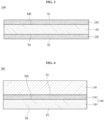
- FIG. 5 is a schematic sectional view showing an electrode 400 for secondary batteries according to another embodiment of the present disclosure.
- the electrode 400 for secondary batteries includes a copper foil 200 and active-material layers 310 and 320 disposed on the copper foil 200.
- the copper foil 200 includes a copper layer 110 and anticorrosive films 210 and 220, which are disposed on opposite surfaces of the copper layer 110.
- the electrode 400 for secondary batteries shown in FIG. 5 includes the two active-material layers 310 and 320, which are disposed respectively on a first surface S1 and a second surface S2 of the copper foil 200.
- the active-material layer 310 which is disposed on the first surface S1 of the copper foil 200, may also be referred to as a first active-material layer
- the active-material layer 320 which is disposed on the second surface S2 of the copper foil 200, may also be referred to as a second active-material layer.
- the two active-material layers 310 and 320 may be made of the same material using the same method, or may be made of different materials using different methods.
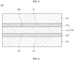
- FIG. 6 is a schematic sectional view showing a secondary battery 500 according to another embodiment of the present disclosure.
- the secondary battery 500 shown in FIG. 6 is, for example, a lithium secondary battery.
- the secondary battery 500 includes a cathode 370, an anode 340 disposed so as to be opposite the cathode 370, an electrolyte 350 for providing an environment in which ions are movable between the cathode 370 and the anode 340, and a separator 360 for electrically isolating the cathode 370 and the anode 340 from each other.
- the ions that move between the cathode 370 and the anode 340 are lithium ions.
- the separator 360 separates the cathode 370 and the anode 340 from each other in order to prevent an electric charge generated in one electrode from moving to the other electrode through the interior of the secondary battery 500 to thus prevent useless consumption of the electric charge.
- the separator 360 is disposed in the electrolyte 350.
- the cathode 370 includes a cathode current collector 371 and a cathode active-material layer 372.
- An aluminum foil may be used as the cathode current collector 371.
- the anode 340 includes an anode current collector 342 and an active-material layer 341.
- the active-material layer 341 of the anode 340 includes an anode active material.
- the copper foil 100 shown in FIG. 1 or the copper foil 200 shown in FIG. 3 may be used as the anode current collector 342.
- the electrode 300 for secondary batteries shown in FIG. 4 or the electrode 400 for secondary batteries shown in FIG. 5 may be used as the anode 340 of the secondary battery 500 shown in FIG. 6 .
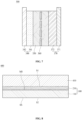
- FIG. 7 is a schematic sectional view showing a flexible copper clad laminate 600 according to another embodiment of the present disclosure.
- the flexible copper clad laminate 600 includes a polymer film 410 and a copper foil 100 disposed on the polymer film 410.
- the flexible copper clad laminate 600 including the copper foil 100 shown in FIG. 1 is shown in FIG. 7 ; however, the embodiment of the present disclosure is not limited thereto.
- the copper foil 200 shown in FIG. 3 or another copper foil may be used in the flexible copper clad laminate 600 according to the embodiment of the present disclosure.
- the polymer film 410 exhibits flexibility and nonconductivity.
- the kind of the polymer film 410 is not particularly restricted.
- the polymer film 410 may include polyimide.
- a polyimide film and the copper foil 100 may be laminated by roll pressing, whereby the flexible copper clad laminate 600 may be manufactured.
- a polyimide precursor solution may be coated on the copper foil 100 and may then be thermally treated, whereby the flexible copper clad laminate 600 may be manufactured.
- the copper foil 100 includes a copper layer 110, having a matte surface MS and a shiny surface SS, and an anticorrosive film 210, disposed on at least one of the matte surface MS or the shiny surface SS of the copper layer 110.
- the anticorrosive film 210 may be omitted.
- the polymer film 410 is disposed on the anticorrosive film 210; however, the embodiment of the present disclosure is not limited thereto.
- the polymer film 410 may be disposed on the shiny surface SS of the copper layer 110.
- FIG. 8 is a schematic view showing a method of manufacturing the copper foil 200 shown in FIG. 3 .
- an electrode plate 13 and a rotary electrode drum 12 which are disposed in an electrolytic solution 11 including copper ions in the state of being spaced apart from each other, are electrically conducted with a current density of 40 to 80 ASD (A/dm 2 ) in order to form a copper layer 110.
- the distance between the electrode plate 13 and the rotary electrode drum 12 may be adjusted to fall within the range of 8 to 13 mm.
- the surface roughness of the copper layer 1 is increased due to the generation of crystal grains.
- the maximum height roughness Rmax of the copper foil 200 may exceed 3.5 ⁇ m, and the Young's modulus of the copper foil 200 may be reduced below 37265 (3800 kgf/mm 2 ).
- the density of the current supplied between the electrode plate 13 and the rotary electrode drum 12 is greater than 80 ASD, on the other hand, the micro-scale reduction of crystal grains may be accelerated. Consequently, the surface roughness of the copper layer 110 may be reduced, whereby the maximum height roughness Rmax of the copper foil 200 may become less than 0.8 ⁇ m. As a result, the force of adhesion between the copper layer 110 and the active-material layer may be reduced.
- the surface roughness of the shiny surface SS of the copper layer 110 may vary depending on the degree of grinding of the surface of the rotary electrode drum 12.
- the surface of the rotary electrode drum 12 may be ground, for example, using a grinding brush having a grit of #800 to #3000.
- variation in the density of current in the rotary electrode drum 12 in the lateral direction thereof is set to 3 % or less.
- nonuniform electroplating may be performed, whereby the copper layer 110 may be nonuniform.
- the modulus bias factor (MBF) of the copper layer is increased.
- the modulus bias factor (MBF) of the copper layer 110 may exceed 0.12.
- the temperature of the electrolytic solution 11 is maintained between 40 and 65°C.
- the density of current or the composition of the electrolytic solution 11 may be adjusted in order to control the surface roughness of the matte surface MS of the copper layer 110.
- the electrolytic solution 11 includes 70 to 90 g/L of copper ions and 50 to 150 g/L of sulfuric acid.
- the electrolytic solution 11 may include an organic additive.
- at least one selected from among hydroxyethyl cellulose (HEC), an organic sulfide, an organic nitride, and thiourea may be used as the organic additive.
- the electrolytic solution 11 includes 0.05 g/L or less of carbon. Specifically, the total amount of carbon TC in the electrolytic solution 11 is 0.05 g/L or less. In the case in which the total amount of carbon TC in the electrolytic solution 11 exceeds 0.05 g/L, a eutectoid may be formed in the copper layer 110 due to the presence of carbon. In the case in which two phases exist in the copper layer 110 due to the eutectoid, the Young's modulus of the copper layer 110 is reduced.
- the electrolytic solution 11 includes 1.0 mg/L or less of chlorine (Cl).
- the chlorine (Cl) includes both chloride ions (Cl - ) and chlorine atoms present in chlorine molecules.
- the chlorine (Cl) may be used to remove silver (Ag) ions introduced into the electrolytic solution 11, for example, when electroplating is performed. Specifically, the chlorine (Cl) may precipitate the silver (Ag) ions in the form of silver chloride (AgCl). The silver chloride (AgCl) may be removed by filtering.
- the recombination of the plated texture is accelerated at the time of heat treatment, whereby the degree of increase of standard stretching of the copper foil 200 may exceed 5.5.
- the electrolytic solution 11 includes 25 mg/L or less of molybdenum (Mo).
- the molybdenum (Mo) includes both molybdenum (Mo) ions and molybdenum (Mo) atoms existing in molybdenum molecules.
- the content of the molybdenum (Mo) exceeds 25 mg/L, the production of a molybdenum-copper alloy may be accelerated, whereby the degree of increase of stretching of the copper layer 110 may be reduced below 2.5.
- a copper wire which is a material for copper ions, may be cleaned. More specifically, the copper wire may be thermally treated in an oxygen atmosphere at a temperature of 600 to 900°C for 30 to 60 minutes in order to remove organic matter from the copper wire, and the thermally treated copper wire may be cleaned using a sulfuric acid solution having a concentration of 10%.
- the electrolytic solution 11 may be circulated at a flow rate of 41 to 45 m 3 /hour.
- the electrolytic solution 11 may be filtered at a flow rate of 41 to 45 m 3 /hour.
- the flow rate of the electrolytic solution is less than 41 m 3 /hour, the flow speed of the electrolytic solution may be low and thus overvoltage is generated, whereby the copper layer 110 may be nonuniformly formed.
- a filter may be damaged, whereby foreign matter may be introduced into the electrolytic solution 11.
- the electrolytic solution 11 may be filtered using activated carbon.
- the electrolytic solution 11 may be ozonized, or hydrogen peroxide and air may be introduced into the electrolytic solution 11.
- Variation in the flow rate of the electrolytic solution 11 that is supplied to an electrolytic bath may be maintained at 5 % or less or at 2 % or less.
- the copper layer 110 is cleaned in a cleaning bath 20.
- acid cleaning for removing impurities, such as a resin ingredient or a natural oxide, from the surface of the copper layer 110 and water cleaning for removing the acidic solution used for acid cleaning may be sequentially performed.
- the cleaning process may be omitted.
- anticorrosive films 210 and 220 are formed on the copper layer 110.
- the copper layer 110 is soaked in an anticorrosive solution 31 contained in an anticorrosion bath 30 in order to form the anticorrosive films 210 and 220 on the copper layer 110.
- the anticorrosive solution 31 may include chrome, and the chrome (Cr) may be present in the anticorrosive solution 31 in an ionic state.
- the anticorrosive solution 31 may include 0.5 to 5 g/L of chrome.
- the temperature of the anticorrosive solution 31 may be maintained between 20 and 40°C.
- the anticorrosive films 210 and 220 thus formed may also be referred to as protective layers.
- each of the anticorrosive films 210 and 220 may include a silane compound formed by silane treatment, or may include a nitrogen compound formed by nitrogen treatment.
- a copper foil 200 is manufactured as the result of forming the protective layers 210 and 220.
- the copper foil 200 is cleaned in a cleaning bath 40. This cleaning process may be omitted.
- a copper foil was manufactured using a foil-manufacturing machine including an electrolytic bath 10, a rotary electrode drum 12 disposed in the electrolytic bath 10, and an electrode plate 13 disposed so as to be spaced apart from the rotary electrode drum 12.
- An electrolytic solution 11 was a copper sulfate solution, the concentration of copper ions in the electrolytic solution 11 was 75 g/L, the concentration of sulfuric acid in the electrolytic solution 11 was 100 g/L, and the temperature of the electrolytic solution 11 was maintained at 55°C.
- the total amount of carbon TC, the content of chlorine (Cl), and the content of molybdenum (Mo) in the electrolytic solution 11 are as shown in Table 1 below.
- the copper layer 110 was cleaned using a cleaning bath 20.
- the copper layer 110 was soaked in an anticorrosive solution 31 contained in an anticorrosion bath 30 in order to form anticorrosive films 210 and 220, each including chrome, on the surface of the copper layer 110.
- the temperature of the anticorrosive solution 31 was maintained at 30°C, and the anticorrosive solution 31 included 2.2g/L of chrome (Cr).
- chrome Cr
- the Young's modulus was measured using a universal testing machine (UTM) according to a method prescribed in the IPC-TM-650 Test Method Manual.
- the width of each sample for measuring the Young's modulus was 12.7 mm, the distance between grips was 50 mm, and the measurement speed was 50 mm/min.
- the Young's modulus of each copper foil was measured three times at three points on the copper foil in the lateral direction thereof.
- the Young's modulus at the point at which the average value was the lowest was taken as the minimum modulus value
- the Young's modulus at the point at which the average value was the highest was taken as the maximum modulus value.
- the overall average of the Young's modulus measured at the three points was taken as the average modulus value.
- each copper foil was measured three times at a normal temperature (23°C ⁇ 3°C), and the average thereof was taken as elongation before heat treatment.
- Each copper foil was thermally treated at 200°C for 30 minutes, the elongation of the thermally treated copper foil was measured three times, and the average thereof was taken as elongation after heat treatment.
- the elongation was measured using a universal testing machine (UTM) according to a method prescribed in the IPC-TM-650 Test Method Manual.
- the width of each sample for measuring the elongation was 12.7 mm, the distance between grips was 50 mm, and the measurement speed was 50 mm/min.
- the degree of increase of standard stretching was calculated using Equation 2 with the elongation before heat treatment and the elongation after heat treatment.
- Degree of increase of standard stretching (elongation after heat treatment) / (elongation before heat treatment)
- XRD X-ray diffraction method
- SBR styrene-butadiene rubber
- CMC carboxymethyl cellulose
- LiPF 6 as a solute, was dissolved in a non-aqueous organic solvent obtained by mixing ethylene carbonate (EC) and ethyl methyl carbonate (EMC) with each other at a ratio of 1:2 so as to have a concentration of 1M in order to manufacture a basic electrolytic solution. 99.5 wt% of the basic electrolytic solution and 0.5 wt% of succinic anhydride were mixed with each other in order to manufacture a non-aqueous electrolytic solution.
- EC ethylene carbonate
- EMC ethyl methyl carbonate
- the slurry thus manufactured was applied to opposite surfaces of an aluminum foil (Al foil) having a thickness of 20 ⁇ m and was then dried in order to manufacture a cathode.
- the cathode and the anode were disposed in an aluminum can so as to be isolated from the aluminum can, and the non-aqueous electrolytic solution and a separator were disposed therebetween in order to manufacture a coin-shaped lithium secondary battery.
- Polypropylene (Celgard 2325; thickness 25 ⁇ m , average pore size ⁇ 28 nm, and porosity 40%) was used as the separator.
- the lithium secondary battery thus manufactured was operated at a charge voltage of 4.3 V and a discharge voltage of 3.4 V in order to measure the capacity per gram of the cathode. Subsequently, the lithium secondary battery was charged and discharged 500 times at a current rate (C-rate) of 0.5 C at a high temperature of 50°C in order to calculate the capacity retention rate of the lithium secondary battery. In the case in which the capacity retention rate of the lithium secondary battery was 80 % or less, the copper foil was determined to be inappropriate for use as an anode current collector of the lithium secondary battery.
- Capacity retention rate (%) [(capacity after 500 charges and discharges) / (capacity after one charge and discharge)] x 100
- each of the lithium secondary batteries manufactured using the copper foils according to Comparative Examples 1 to 5 has a capacity retention rate such that each of the copper foils according to Comparative Examples 1 to 5 is evaluated to be inappropriate as an anode current collector of the lithium secondary battery.
- each of the lithium secondary batteries manufactured using the following copper foils does not have a sufficient capacity retention rate (a capacity retention rate of 80% or more):
- each of the lithium secondary batteries manufactured using the copper foils according to Manufacturing Examples 1 to 6 manufactured under conditions according to the embodiments of the present disclosure has a capacity retention rate of more than 80%.
Landscapes
- Chemical & Material Sciences (AREA)
- Engineering & Computer Science (AREA)
- Chemical Kinetics & Catalysis (AREA)
- Electrochemistry (AREA)
- Materials Engineering (AREA)
- General Chemical & Material Sciences (AREA)
- Metallurgy (AREA)
- Organic Chemistry (AREA)
- Microelectronics & Electronic Packaging (AREA)
- Manufacturing & Machinery (AREA)
- Composite Materials (AREA)
- Cell Electrode Carriers And Collectors (AREA)
- Battery Electrode And Active Subsutance (AREA)
- Other Surface Treatments For Metallic Materials (AREA)
- Secondary Cells (AREA)
- Chemical Treatment Of Metals (AREA)
Claims (14)
- Kupferfolie, umfassend:eine Kupferschicht; undeinen Korrosionsschutzfilm, der auf der Kupferschicht angeordnet ist, wobei die Kupferfolie einen Elastizitätsmodul von 37265 bis 45111 MPa (3800 bis 4600 kgf/mm2) und einen Modul-Bias-Faktor (MBF) von weniger als 0,12 aufweist undder Modul-Bias-Faktor (MBF) anhand der nachstehenden Gleichung 1 berechnet wird
MBF = (maximaler Modulwert - minimaler Modulwert)/(durchschnittlicher Modulwert) wobei in einem Fall, in dem der Elastizitätsmodul der Kupferfolie dreimal an drei Punkten auf der Kupferfolie in einer seitlichen Richtung derselben gemessen wird, der Elastizitätsmodul an einem Punkt, an dem ein Durchschnittswert desselben am niedrigsten ist, der minimale Modulwert ist, der Elastizitätsmodul an einem Punkt, an dem der Durchschnittswert desselben am höchsten ist, der maximale Modulwert ist, und ein Gesamtdurchschnitt des an den drei Punkten gemessenen Elastizitätsmoduls der durchschnittliche Modulwert ist. - Kupferfolie nach Anspruch 1, wobei die Kupferfolie einen Steigerungsgrad der Standarddehnung, der ein Verhältnis der Dehnung nach einer Wärmebehandlung bei 200°C für 30 Minuten zur Dehnung vor der Wärmebehandlung ist, von 2,5 bis 5,5 aufweist.
- Kupferfolie nach Anspruch 1, wobei die Kupferfolie eine Streckgrenze von 205 bis 618 MPa (21 bis 63 kgf/mm2) bei einer Normaltemperatur von 23 ± 3 ° C aufweist.
- Kupferfolie nach Anspruch 1, wobei die Kupferfolie eine maximale Höhenrauhigkeit (Rmax) von 0,8 µm bis 3,5 µm aufweist.
- Kupferfolie nach Anspruch 1, wobeidie Kupferfolie eine (220)-Ebene aufweist, undein Texturkoeffizient (TC(220)) der (220)-Ebene 0,48 bis 1,28 beträgt.
- Kupferfolie nach Anspruch 1, wobei der Korrosionsschutzfilm mindestens eines aus Chrom, einer Silanverbindung oder einer Stickstoffverbindung umfasst.
- Kupferfolie nach Anspruch 1, wobei die Kupferfolie eine Dicke von 4 µm bis 30 µm aufweist.
- Elektrode für Sekundärbatterien, wobei die Elektrode umfasst:die Kupferfolie nach einem der Ansprüche 1 bis 7; undeine Schicht aus aktivem Material, die auf der Kupferfolie angeordnet ist.
- Sekundärbatterie, umfassend:eine Kathode;eine Anode, die so angeordnet ist, dass sie der Kathode gegenüberliegt;einen Elektrolyten, der zwischen der Kathode und der Anode angeordnet ist, um eine Umgebung bereitzustellen, in der Lithiumionen zwischen ihnen beweglich sind; undeinen Separator zum elektrischen Isolieren der Kathode und der Anode voneinander, wobeidie Anode umfasst:die Kupferfolie nach einem der Ansprüche 1 bis 7; undeine Schicht aus aktivem Material, die auf der Kupferfolie angeordnet ist.
- Flexibles kupferkaschiertes Laminat, umfassend:einen Polymerfilm; unddie Kupferfolie nach einem der Ansprüche 1 bis 7, wobei die Kupferfolie auf dem Polymerfilm angeordnet ist.
- Verfahren zur Herstellung der Kupferfolie nach einem der Ansprüche 1 bis 7, wobei das Verfahren umfasst:elektrisches Leiten einer Elektrodenplatte und einer rotierenden Elektrodentrommel, die in einer Elektrolytlösung, die Kupferionen enthält, in einem Zustand angeordnet sind, in dem sie voneinander beabstandet sind, mit einer Stromdichte von 40 bis 80 A/dm2, um eine Kupferschicht zu bilden, undTränken der Kupferschicht in einer Korrosionsschutzlösung,wobeidie Elektrolytlösung umfasst:70 bis 90 g/L Kupferionen;50 bis 150 g/L Schwefelsäure;weniger als 0,05 g/L Kohlenstoff;1,0 mg/L oder weniger Chlor (Cl); und25 mg/L oder weniger Molybdän (Mo).
- Verfahren nach Anspruch 11, wobei die Schwankung der Stromdichte in der rotierenden Elektrodentrommel in ihrer seitlichen Richtung 3% oder weniger beträgt.
- Verfahren nach Anspruch 11, wobei die Elektrolytlösung eine Durchflussrate von 41 bis 45 m3/Stunde aufweist.
- Verfahren nach Anspruch 11, wobei die Korrosionsschutzlösung Chrom (Cr) enthält.
Applications Claiming Priority (2)
| Application Number | Priority Date | Filing Date | Title |
|---|---|---|---|
| KR1020170025581A KR102646185B1 (ko) | 2017-02-27 | 2017-02-27 | 우수한 접착력을 갖는 동박, 그것을 포함하는 전극, 그것을 포함하는 이차전지, 및 그것의 제조방법 |
| PCT/KR2018/002311 WO2018155972A2 (ko) | 2017-02-27 | 2018-02-26 | 우수한 접착력을 갖는 동박, 그것을 포함하는 전극, 그것을 포함하는 이차전지, 및 그것의 제조방법 |
Publications (3)
| Publication Number | Publication Date |
|---|---|
| EP3588640A2 EP3588640A2 (de) | 2020-01-01 |
| EP3588640A4 EP3588640A4 (de) | 2020-12-16 |
| EP3588640B1 true EP3588640B1 (de) | 2024-08-28 |
Family
ID=63253867
Family Applications (1)
| Application Number | Title | Priority Date | Filing Date |
|---|---|---|---|
| EP18757189.8A Active EP3588640B1 (de) | 2017-02-27 | 2018-02-26 | Kupferfolie mit hervorragender haftfestigkeit, elektrode damit, sekundärbatterie damit und herstellungsverfahren dafür |
Country Status (9)
| Country | Link |
|---|---|
| US (1) | US11588156B2 (de) |
| EP (1) | EP3588640B1 (de) |
| JP (2) | JP2020508399A (de) |
| KR (1) | KR102646185B1 (de) |
| CN (1) | CN110495028B (de) |
| ES (1) | ES2988913T3 (de) |
| HU (1) | HUE068118T2 (de) |
| PL (1) | PL3588640T3 (de) |
| WO (1) | WO2018155972A2 (de) |
Families Citing this family (7)
| Publication number | Priority date | Publication date | Assignee | Title |
|---|---|---|---|---|
| KR20210062369A (ko) * | 2019-11-21 | 2021-05-31 | 에스케이넥실리스 주식회사 | 찢김 또는 주름 불량을 방지할 수 있는 전해동박, 그것을 포함하는 전극, 그것을 포함하는 이차전지, 및 그것의 제조방법 |
| KR20220043617A (ko) * | 2020-09-29 | 2022-04-05 | 에스케이넥실리스 주식회사 | 고강도 전해동박, 그것을 포함하는 전극, 그것을 포함하는 이차전지 및 그것의 제조방법 |
| WO2022091407A1 (ja) * | 2020-11-02 | 2022-05-05 | TeraWatt Technology株式会社 | リチウム2次電池 |
| CA3172526A1 (en) * | 2021-10-07 | 2023-04-07 | Circuit Foil Luxembourg | Copper foil with high energy at break and secondary battery comprising the same |
| WO2023057067A1 (en) * | 2021-10-07 | 2023-04-13 | Circuit Foil Luxembourg | Copper foil with high engery at break and secondary battery comprising the same |
| JP1744471S (ja) * | 2022-06-17 | 2023-05-18 | 銅箔製造装置用陽極板 | |
| CN120473465B (zh) * | 2025-05-29 | 2026-01-30 | 捷成微系统(惠州)股份有限公司 | 一种集流体复合铜箔展膜方法和装置 |
Family Cites Families (20)
| Publication number | Priority date | Publication date | Assignee | Title |
|---|---|---|---|---|
| JP2594840B2 (ja) * | 1990-05-31 | 1997-03-26 | 日鉱グールド・フォイル株式会社 | 電解銅箔の製造方法及び装置 |
| MY138622A (en) | 1990-12-19 | 2009-07-31 | Nikko Gould Foil Kk | Method of producing electrolytic copper foil |
| JPH07202367A (ja) * | 1993-12-28 | 1995-08-04 | Japan Energy Corp | 印刷回路用銅箔の表面処理方法 |
| JP3307232B2 (ja) * | 1996-07-22 | 2002-07-24 | 凸版印刷株式会社 | 高分子量脂肪族ポリエステル共重合体の製造方法 |
| JP3463048B2 (ja) | 2001-06-11 | 2003-11-05 | 三井金属鉱業株式会社 | 金属箔電解製造装置 |
| JP3770537B2 (ja) * | 2001-07-30 | 2006-04-26 | 三井金属鉱業株式会社 | キャパシター及びそれを形成するための両面銅張積層板の製造方法 |
| JP4712759B2 (ja) * | 2006-06-07 | 2011-06-29 | 古河電気工業株式会社 | 表面処理電解銅箔及びその製造方法、並びに回路基板 |
| TWI414638B (zh) * | 2006-06-07 | 2013-11-11 | Furukawa Electric Co Ltd | A method for manufacturing a surface-treated electrolytic copper foil, and a circuit board |
| WO2008132987A1 (ja) * | 2007-04-20 | 2008-11-06 | Nippon Mining & Metals Co., Ltd. | リチウム二次電池用電解銅箔及び該銅箔の製造方法 |
| JP5321788B2 (ja) * | 2007-05-23 | 2013-10-23 | ソニー株式会社 | 二次電池用集電体、二次電池用負極、二次電池および電子機器 |
| JP2009256772A (ja) | 2008-03-17 | 2009-11-05 | Akahoshi Kogyo Kk | 電解金属箔製造装置における電極基体 |
| WO2011108467A1 (ja) | 2010-03-01 | 2011-09-09 | 古河電気工業株式会社 | 銅箔の表面処理方法、表面処理銅箔およびリチウムイオン二次電池の負極集電体用銅箔 |
| JP2012001786A (ja) * | 2010-06-18 | 2012-01-05 | Jx Nippon Mining & Metals Corp | フレキシブル銅張積層板及びその製造方法 |
| KR20160138321A (ko) | 2011-06-30 | 2016-12-02 | 후루카와 덴키 고교 가부시키가이샤 | 전해 동박, 상기 전해 동박의 제조 방법 및 상기 전해 동박을 집전체로 하는 리튬 이온 이차 전지 |
| JP5718426B2 (ja) | 2012-10-31 | 2015-05-13 | 古河電気工業株式会社 | 銅箔、非水電解質二次電池用負極および非水電解質二次電池 |
| TW201448338A (zh) * | 2013-01-18 | 2014-12-16 | Furukawa Electric Co Ltd | 銅箔、鋰離子電池用負極及鋰離子二次電池 |
| TWI518210B (zh) | 2013-01-31 | 2016-01-21 | 三井金屬鑛業股份有限公司 | 電解銅箔、該電解銅箔之製造方法及使用該電解銅箔而得之表面處理銅箔 |
| WO2014156638A1 (ja) * | 2013-03-26 | 2014-10-02 | 古河電気工業株式会社 | 全固体二次電池 |
| KR101816801B1 (ko) * | 2015-02-06 | 2018-01-11 | 엘에스엠트론 주식회사 | 이차전지용 동박 및 이를 포함하는 이차전지 |
| KR101897474B1 (ko) | 2015-06-26 | 2018-09-12 | 케이씨에프테크놀로지스 주식회사 | 리튬 이차전지용 전해동박 및 이를 포함하는 리튬 이차전지 |
-
2017
- 2017-02-27 KR KR1020170025581A patent/KR102646185B1/ko active Active
-
2018
- 2018-02-26 JP JP2019546314A patent/JP2020508399A/ja active Pending
- 2018-02-26 PL PL18757189.8T patent/PL3588640T3/pl unknown
- 2018-02-26 EP EP18757189.8A patent/EP3588640B1/de active Active
- 2018-02-26 WO PCT/KR2018/002311 patent/WO2018155972A2/ko not_active Ceased
- 2018-02-26 CN CN201880024525.5A patent/CN110495028B/zh active Active
- 2018-02-26 US US16/489,021 patent/US11588156B2/en active Active
- 2018-02-26 HU HUE18757189A patent/HUE068118T2/hu unknown
- 2018-02-26 ES ES18757189T patent/ES2988913T3/es active Active
-
2021
- 2021-09-09 JP JP2021147000A patent/JP2021193214A/ja active Pending
Also Published As
| Publication number | Publication date |
|---|---|
| KR20180098875A (ko) | 2018-09-05 |
| JP2020508399A (ja) | 2020-03-19 |
| WO2018155972A3 (ko) | 2018-12-20 |
| KR102646185B1 (ko) | 2024-03-08 |
| CN110495028A (zh) | 2019-11-22 |
| HUE068118T2 (hu) | 2024-12-28 |
| EP3588640A2 (de) | 2020-01-01 |
| EP3588640A4 (de) | 2020-12-16 |
| US11588156B2 (en) | 2023-02-21 |
| CN110495028B (zh) | 2022-09-23 |
| US20200006777A1 (en) | 2020-01-02 |
| WO2018155972A2 (ko) | 2018-08-30 |
| ES2988913T3 (es) | 2024-11-22 |
| PL3588640T3 (pl) | 2024-12-09 |
| JP2021193214A (ja) | 2021-12-23 |
Similar Documents
| Publication | Publication Date | Title |
|---|---|---|
| EP3588640B1 (de) | Kupferfolie mit hervorragender haftfestigkeit, elektrode damit, sekundärbatterie damit und herstellungsverfahren dafür | |
| EP3288101B1 (de) | Elektrolytische kupferfolie, elektrode für die sekundärbatterie, lithiumionen-sekundärbatterie und verfahren zu ihrer herstellung | |
| EP3121885B9 (de) | Elektrolytische kupferfolie und sammler, negativelektrode und lithiumbatterie damit | |
| EP4243145A2 (de) | Elektrolytische kupferfolie zur verhinderung von aufreiss- oder faltendefekten, elektrode damit, sekundärbatterie damit und verfahren zur herstellung davon | |
| EP3121884B1 (de) | Elektrolytische kupferfolie und sammler, negativelektrode und lithiumbatterie damit | |
| EP3951021A1 (de) | Kupferfolie mit antifalteneigenschaft, elektrode damit, sekundärbatterie damit und herstellungsverfahren dafür | |
| CN105637106A (zh) | 铜合金箔 | |
| JP6527219B2 (ja) | 最適化したピーク粗さを有する電解銅箔、それを含む電極、それを含む二次電池、およびその製造方法 | |
| KR20160138321A (ko) | 전해 동박, 상기 전해 동박의 제조 방법 및 상기 전해 동박을 집전체로 하는 리튬 이온 이차 전지 | |
| EP3919655A1 (de) | Gegen riss- und faltdefekte sicherer elektrolytischer kupferfolienschutz, elektrode damit, sekundärbatterie damit und herstellungsverfahren dafür | |
| KR102546687B1 (ko) | 고용량 이차전지 제조를 가능하게 하는 동박, 그것을 포함하는 전극, 그것을 포함하는 이차전지, 및 그것의 제조방법 | |
| CN108270016A (zh) | 电解铜箔、电极、二次电池及其制造方法 | |
| KR20180090532A (ko) | 주름 및 말림이 최소화된 고강도 전해동박, 그것을 포함하는 전극, 그것을 포함하는 이차전지, 및 그것의 제조방법 | |
| KR20180137853A (ko) | 울음과 찢김이 최소화된 동박, 그것을 포함하는 전극, 그것을 포함하는 이차전지, 및 그것의 제조 방법 | |
| EP3404755A1 (de) | Kupferfolie, verfahren zur herstellung davon, elektrode damit und sekundärbatterie damit | |
| KR20180117814A (ko) | 친수성 고분자층을 가져 우수한 접착력을 갖는 동박, 그것을 포함하는 전극, 그것을 포함하는 이차전지, 및 그것의 제조방법 | |
| KR102492813B1 (ko) | 핸들링성이 우수한 고용량 이차전지용 동박, 그것을 포함하는 전극, 그것을 포함하는 이차전지, 및 그것의 제조방법 | |
| KR20180100939A (ko) | 주름과 찢김이 최소화된 동박, 그것을 포함하는 전극, 그것을 포함하는 이차전지, 및 그것의 제조 방법 | |
| KR20180117838A (ko) | 이미다졸 화합물층을 포함하여 우수한 접착력을 갖는 동박, 그것을 포함하는 전극, 그것을 포함하는 이차전지, 및 그것의 제조방법 | |
| EP3608448B1 (de) | Kupferfolie mit minimierten ausbeulverhalten und rissigkeit, elektrode damit, sekundärbatterie damit und verfahren zur herstellung damit | |
| KR102518398B1 (ko) | 고신뢰성 동박, 그것을 포함하는 전극, 그것을 포함하는 이차전지, 및 그것의 제조 방법 |
Legal Events
| Date | Code | Title | Description |
|---|---|---|---|
| STAA | Information on the status of an ep patent application or granted ep patent |
Free format text: STATUS: THE INTERNATIONAL PUBLICATION HAS BEEN MADE |
|
| PUAI | Public reference made under article 153(3) epc to a published international application that has entered the european phase |
Free format text: ORIGINAL CODE: 0009012 |
|
| STAA | Information on the status of an ep patent application or granted ep patent |
Free format text: STATUS: REQUEST FOR EXAMINATION WAS MADE |
|
| 17P | Request for examination filed |
Effective date: 20190829 |
|
| AK | Designated contracting states |
Kind code of ref document: A2 Designated state(s): AL AT BE BG CH CY CZ DE DK EE ES FI FR GB GR HR HU IE IS IT LI LT LU LV MC MK MT NL NO PL PT RO RS SE SI SK SM TR |
|
| AX | Request for extension of the european patent |
Extension state: BA ME |
|
| DAV | Request for validation of the european patent (deleted) | ||
| DAX | Request for extension of the european patent (deleted) | ||
| A4 | Supplementary search report drawn up and despatched |
Effective date: 20201113 |
|
| RIC1 | Information provided on ipc code assigned before grant |
Ipc: H01M 10/052 20100101ALI20201109BHEP Ipc: C25D 1/04 20060101ALI20201109BHEP Ipc: H01M 4/66 20060101AFI20201109BHEP Ipc: C25D 1/20 20060101ALI20201109BHEP Ipc: H01M 4/13 20100101ALI20201109BHEP |
|
| RAP1 | Party data changed (applicant data changed or rights of an application transferred) |
Owner name: SK NEXILIS CO., LTD. |
|
| GRAP | Despatch of communication of intention to grant a patent |
Free format text: ORIGINAL CODE: EPIDOSNIGR1 |
|
| STAA | Information on the status of an ep patent application or granted ep patent |
Free format text: STATUS: GRANT OF PATENT IS INTENDED |
|
| INTG | Intention to grant announced |
Effective date: 20240325 |
|
| GRAS | Grant fee paid |
Free format text: ORIGINAL CODE: EPIDOSNIGR3 |
|
| GRAA | (expected) grant |
Free format text: ORIGINAL CODE: 0009210 |
|
| STAA | Information on the status of an ep patent application or granted ep patent |
Free format text: STATUS: THE PATENT HAS BEEN GRANTED |
|
| P01 | Opt-out of the competence of the unified patent court (upc) registered |
Free format text: CASE NUMBER: APP_36798/2024 Effective date: 20240620 |
|
| AK | Designated contracting states |
Kind code of ref document: B1 Designated state(s): AL AT BE BG CH CY CZ DE DK EE ES FI FR GB GR HR HU IE IS IT LI LT LU LV MC MK MT NL NO PL PT RO RS SE SI SK SM TR |
|
| REG | Reference to a national code |
Ref country code: GB Ref legal event code: FG4D |
|
| REG | Reference to a national code |
Ref country code: CH Ref legal event code: EP |
|
| REG | Reference to a national code |
Ref country code: DE Ref legal event code: R096 Ref document number: 602018073638 Country of ref document: DE |
|
| REG | Reference to a national code |
Ref country code: IE Ref legal event code: FG4D |
|
| REG | Reference to a national code |
Ref country code: SE Ref legal event code: TRGR |
|
| REG | Reference to a national code |
Ref country code: ES Ref legal event code: FG2A Ref document number: 2988913 Country of ref document: ES Kind code of ref document: T3 Effective date: 20241122 |
|
| REG | Reference to a national code |
Ref country code: LT Ref legal event code: MG9D |
|
| REG | Reference to a national code |
Ref country code: HU Ref legal event code: AG4A Ref document number: E068118 Country of ref document: HU |
|
| REG | Reference to a national code |
Ref country code: AT Ref legal event code: MK05 Ref document number: 1718987 Country of ref document: AT Kind code of ref document: T Effective date: 20240828 |
|
| PG25 | Lapsed in a contracting state [announced via postgrant information from national office to epo] |
Ref country code: NL Free format text: LAPSE BECAUSE OF FAILURE TO SUBMIT A TRANSLATION OF THE DESCRIPTION OR TO PAY THE FEE WITHIN THE PRESCRIBED TIME-LIMIT Effective date: 20240828 Ref country code: GR Free format text: LAPSE BECAUSE OF FAILURE TO SUBMIT A TRANSLATION OF THE DESCRIPTION OR TO PAY THE FEE WITHIN THE PRESCRIBED TIME-LIMIT Effective date: 20241129 Ref country code: PT Free format text: LAPSE BECAUSE OF FAILURE TO SUBMIT A TRANSLATION OF THE DESCRIPTION OR TO PAY THE FEE WITHIN THE PRESCRIBED TIME-LIMIT Effective date: 20241230 Ref country code: FI Free format text: LAPSE BECAUSE OF FAILURE TO SUBMIT A TRANSLATION OF THE DESCRIPTION OR TO PAY THE FEE WITHIN THE PRESCRIBED TIME-LIMIT Effective date: 20240828 |
|
| PG25 | Lapsed in a contracting state [announced via postgrant information from national office to epo] |
Ref country code: BG Free format text: LAPSE BECAUSE OF FAILURE TO SUBMIT A TRANSLATION OF THE DESCRIPTION OR TO PAY THE FEE WITHIN THE PRESCRIBED TIME-LIMIT Effective date: 20240828 |
|
| PG25 | Lapsed in a contracting state [announced via postgrant information from national office to epo] |
Ref country code: LV Free format text: LAPSE BECAUSE OF FAILURE TO SUBMIT A TRANSLATION OF THE DESCRIPTION OR TO PAY THE FEE WITHIN THE PRESCRIBED TIME-LIMIT Effective date: 20240828 |
|
| REG | Reference to a national code |
Ref country code: NL Ref legal event code: MP Effective date: 20240828 |
|
| PG25 | Lapsed in a contracting state [announced via postgrant information from national office to epo] |
Ref country code: IS Free format text: LAPSE BECAUSE OF FAILURE TO SUBMIT A TRANSLATION OF THE DESCRIPTION OR TO PAY THE FEE WITHIN THE PRESCRIBED TIME-LIMIT Effective date: 20241228 Ref country code: AT Free format text: LAPSE BECAUSE OF FAILURE TO SUBMIT A TRANSLATION OF THE DESCRIPTION OR TO PAY THE FEE WITHIN THE PRESCRIBED TIME-LIMIT Effective date: 20240828 |
|
| PG25 | Lapsed in a contracting state [announced via postgrant information from national office to epo] |
Ref country code: HR Free format text: LAPSE BECAUSE OF FAILURE TO SUBMIT A TRANSLATION OF THE DESCRIPTION OR TO PAY THE FEE WITHIN THE PRESCRIBED TIME-LIMIT Effective date: 20240828 |
|
| PG25 | Lapsed in a contracting state [announced via postgrant information from national office to epo] |
Ref country code: RS Free format text: LAPSE BECAUSE OF FAILURE TO SUBMIT A TRANSLATION OF THE DESCRIPTION OR TO PAY THE FEE WITHIN THE PRESCRIBED TIME-LIMIT Effective date: 20241128 |
|
| PG25 | Lapsed in a contracting state [announced via postgrant information from national office to epo] |
Ref country code: RS Free format text: LAPSE BECAUSE OF FAILURE TO SUBMIT A TRANSLATION OF THE DESCRIPTION OR TO PAY THE FEE WITHIN THE PRESCRIBED TIME-LIMIT Effective date: 20241128 Ref country code: PT Free format text: LAPSE BECAUSE OF FAILURE TO SUBMIT A TRANSLATION OF THE DESCRIPTION OR TO PAY THE FEE WITHIN THE PRESCRIBED TIME-LIMIT Effective date: 20241230 Ref country code: NL Free format text: LAPSE BECAUSE OF FAILURE TO SUBMIT A TRANSLATION OF THE DESCRIPTION OR TO PAY THE FEE WITHIN THE PRESCRIBED TIME-LIMIT Effective date: 20240828 Ref country code: LV Free format text: LAPSE BECAUSE OF FAILURE TO SUBMIT A TRANSLATION OF THE DESCRIPTION OR TO PAY THE FEE WITHIN THE PRESCRIBED TIME-LIMIT Effective date: 20240828 Ref country code: IS Free format text: LAPSE BECAUSE OF FAILURE TO SUBMIT A TRANSLATION OF THE DESCRIPTION OR TO PAY THE FEE WITHIN THE PRESCRIBED TIME-LIMIT Effective date: 20241228 Ref country code: HR Free format text: LAPSE BECAUSE OF FAILURE TO SUBMIT A TRANSLATION OF THE DESCRIPTION OR TO PAY THE FEE WITHIN THE PRESCRIBED TIME-LIMIT Effective date: 20240828 Ref country code: GR Free format text: LAPSE BECAUSE OF FAILURE TO SUBMIT A TRANSLATION OF THE DESCRIPTION OR TO PAY THE FEE WITHIN THE PRESCRIBED TIME-LIMIT Effective date: 20241129 Ref country code: FI Free format text: LAPSE BECAUSE OF FAILURE TO SUBMIT A TRANSLATION OF THE DESCRIPTION OR TO PAY THE FEE WITHIN THE PRESCRIBED TIME-LIMIT Effective date: 20240828 Ref country code: BG Free format text: LAPSE BECAUSE OF FAILURE TO SUBMIT A TRANSLATION OF THE DESCRIPTION OR TO PAY THE FEE WITHIN THE PRESCRIBED TIME-LIMIT Effective date: 20240828 Ref country code: AT Free format text: LAPSE BECAUSE OF FAILURE TO SUBMIT A TRANSLATION OF THE DESCRIPTION OR TO PAY THE FEE WITHIN THE PRESCRIBED TIME-LIMIT Effective date: 20240828 |
|
| PGFP | Annual fee paid to national office [announced via postgrant information from national office to epo] |
Ref country code: HU Payment date: 20250117 Year of fee payment: 8 |
|
| PGFP | Annual fee paid to national office [announced via postgrant information from national office to epo] |
Ref country code: DE Payment date: 20241223 Year of fee payment: 8 |
|
| PG25 | Lapsed in a contracting state [announced via postgrant information from national office to epo] |
Ref country code: DK Free format text: LAPSE BECAUSE OF FAILURE TO SUBMIT A TRANSLATION OF THE DESCRIPTION OR TO PAY THE FEE WITHIN THE PRESCRIBED TIME-LIMIT Effective date: 20240828 Ref country code: SM Free format text: LAPSE BECAUSE OF FAILURE TO SUBMIT A TRANSLATION OF THE DESCRIPTION OR TO PAY THE FEE WITHIN THE PRESCRIBED TIME-LIMIT Effective date: 20240828 Ref country code: RO Free format text: LAPSE BECAUSE OF FAILURE TO SUBMIT A TRANSLATION OF THE DESCRIPTION OR TO PAY THE FEE WITHIN THE PRESCRIBED TIME-LIMIT Effective date: 20240828 |
|
| PGFP | Annual fee paid to national office [announced via postgrant information from national office to epo] |
Ref country code: ES Payment date: 20250314 Year of fee payment: 8 |
|
| PG25 | Lapsed in a contracting state [announced via postgrant information from national office to epo] |
Ref country code: EE Free format text: LAPSE BECAUSE OF FAILURE TO SUBMIT A TRANSLATION OF THE DESCRIPTION OR TO PAY THE FEE WITHIN THE PRESCRIBED TIME-LIMIT Effective date: 20240828 |
|
| PGFP | Annual fee paid to national office [announced via postgrant information from national office to epo] |
Ref country code: CH Payment date: 20250301 Year of fee payment: 8 |
|
| PG25 | Lapsed in a contracting state [announced via postgrant information from national office to epo] |
Ref country code: SK Free format text: LAPSE BECAUSE OF FAILURE TO SUBMIT A TRANSLATION OF THE DESCRIPTION OR TO PAY THE FEE WITHIN THE PRESCRIBED TIME-LIMIT Effective date: 20240828 |
|
| PGFP | Annual fee paid to national office [announced via postgrant information from national office to epo] |
Ref country code: IT Payment date: 20241224 Year of fee payment: 8 |
|
| PGFP | Annual fee paid to national office [announced via postgrant information from national office to epo] |
Ref country code: TR Payment date: 20250108 Year of fee payment: 8 |
|
| REG | Reference to a national code |
Ref country code: DE Ref legal event code: R097 Ref document number: 602018073638 Country of ref document: DE |
|
| PLBE | No opposition filed within time limit |
Free format text: ORIGINAL CODE: 0009261 |
|
| STAA | Information on the status of an ep patent application or granted ep patent |
Free format text: STATUS: NO OPPOSITION FILED WITHIN TIME LIMIT |
|
| 26N | No opposition filed |
Effective date: 20250530 |
|
| PG25 | Lapsed in a contracting state [announced via postgrant information from national office to epo] |
Ref country code: MC Free format text: LAPSE BECAUSE OF FAILURE TO SUBMIT A TRANSLATION OF THE DESCRIPTION OR TO PAY THE FEE WITHIN THE PRESCRIBED TIME-LIMIT Effective date: 20240828 |
|
| GBPC | Gb: european patent ceased through non-payment of renewal fee |
Effective date: 20250226 |
|
| PG25 | Lapsed in a contracting state [announced via postgrant information from national office to epo] |
Ref country code: GB Free format text: LAPSE BECAUSE OF NON-PAYMENT OF DUE FEES Effective date: 20250226 |
|
| PGFP | Annual fee paid to national office [announced via postgrant information from national office to epo] |
Ref country code: NO Payment date: 20251223 Year of fee payment: 9 |
|
| PGFP | Annual fee paid to national office [announced via postgrant information from national office to epo] |
Ref country code: LU Payment date: 20251223 Year of fee payment: 9 Ref country code: FR Payment date: 20251223 Year of fee payment: 9 |
|
| PGFP | Annual fee paid to national office [announced via postgrant information from national office to epo] |
Ref country code: BE Payment date: 20251229 Year of fee payment: 9 |
|
| PGFP | Annual fee paid to national office [announced via postgrant information from national office to epo] |
Ref country code: SE Payment date: 20251223 Year of fee payment: 9 |
|
| PG25 | Lapsed in a contracting state [announced via postgrant information from national office to epo] |
Ref country code: IE Free format text: LAPSE BECAUSE OF NON-PAYMENT OF DUE FEES Effective date: 20250226 |
|
| PGFP | Annual fee paid to national office [announced via postgrant information from national office to epo] |
Ref country code: CZ Payment date: 20251223 Year of fee payment: 9 |
|
| PGFP | Annual fee paid to national office [announced via postgrant information from national office to epo] |
Ref country code: PL Payment date: 20251229 Year of fee payment: 9 |