EP3581731B1 - Paneel - Google Patents
Paneel Download PDFInfo
- Publication number
- EP3581731B1 EP3581731B1 EP18178061.0A EP18178061A EP3581731B1 EP 3581731 B1 EP3581731 B1 EP 3581731B1 EP 18178061 A EP18178061 A EP 18178061A EP 3581731 B1 EP3581731 B1 EP 3581731B1
- Authority
- EP
- European Patent Office
- Prior art keywords
- panel
- locking
- tongue
- edge
- groove wall
- Prior art date
- Legal status (The legal status is an assumption and is not a legal conclusion. Google has not performed a legal analysis and makes no representation as to the accuracy of the status listed.)
- Active
Links
- 230000007704 transition Effects 0.000 claims description 14
- 230000000295 complement effect Effects 0.000 claims description 8
- 238000005304 joining Methods 0.000 claims description 5
- 239000012876 carrier material Substances 0.000 description 12
- 230000000694 effects Effects 0.000 description 6
- 230000008901 benefit Effects 0.000 description 5
- 239000002245 particle Substances 0.000 description 5
- 230000005489 elastic deformation Effects 0.000 description 4
- 239000000945 filler Substances 0.000 description 4
- 239000011159 matrix material Substances 0.000 description 4
- 239000000758 substrate Substances 0.000 description 4
- 239000008187 granular material Substances 0.000 description 3
- 238000000034 method Methods 0.000 description 3
- 239000012764 mineral filler Substances 0.000 description 3
- 230000008569 process Effects 0.000 description 3
- 239000011343 solid material Substances 0.000 description 3
- 239000000454 talc Substances 0.000 description 3
- 229910052623 talc Inorganic materials 0.000 description 3
- 239000004743 Polypropylene Substances 0.000 description 2
- 239000011248 coating agent Substances 0.000 description 2
- 238000000576 coating method Methods 0.000 description 2
- 230000008878 coupling Effects 0.000 description 2
- 238000010168 coupling process Methods 0.000 description 2
- 238000005859 coupling reaction Methods 0.000 description 2
- 238000013016 damping Methods 0.000 description 2
- 210000003746 feather Anatomy 0.000 description 2
- 229910052500 inorganic mineral Inorganic materials 0.000 description 2
- 238000004519 manufacturing process Methods 0.000 description 2
- 230000013011 mating Effects 0.000 description 2
- 239000011707 mineral Substances 0.000 description 2
- 230000004048 modification Effects 0.000 description 2
- 238000012986 modification Methods 0.000 description 2
- 239000004033 plastic Substances 0.000 description 2
- 229920003023 plastic Polymers 0.000 description 2
- -1 polyethylene terephthalate Polymers 0.000 description 2
- 229920000139 polyethylene terephthalate Polymers 0.000 description 2
- 239000005020 polyethylene terephthalate Substances 0.000 description 2
- 229920001155 polypropylene Polymers 0.000 description 2
- 239000012815 thermoplastic material Substances 0.000 description 2
- 241001148661 Cenchrus longisetus Species 0.000 description 1
- 230000009471 action Effects 0.000 description 1
- 238000010009 beating Methods 0.000 description 1
- 238000010924 continuous production Methods 0.000 description 1
- 239000007799 cork Substances 0.000 description 1
- 238000005034 decoration Methods 0.000 description 1
- 238000006073 displacement reaction Methods 0.000 description 1
- 230000002349 favourable effect Effects 0.000 description 1
- 239000003365 glass fiber Substances 0.000 description 1
- 230000006872 improvement Effects 0.000 description 1
- 238000007373 indentation Methods 0.000 description 1
- 239000004922 lacquer Substances 0.000 description 1
- 238000003754 machining Methods 0.000 description 1
- 229910052615 phyllosilicate Inorganic materials 0.000 description 1
- 229920002635 polyurethane Polymers 0.000 description 1
- 239000004814 polyurethane Substances 0.000 description 1
- 239000011435 rock Substances 0.000 description 1
- 229920001169 thermoplastic Polymers 0.000 description 1
- 239000004416 thermosoftening plastic Substances 0.000 description 1
Images
Classifications
-
- E—FIXED CONSTRUCTIONS
- E04—BUILDING
- E04F—FINISHING WORK ON BUILDINGS, e.g. STAIRS, FLOORS
- E04F15/00—Flooring
- E04F15/02—Flooring or floor layers composed of a number of similar elements
- E04F15/02038—Flooring or floor layers composed of a number of similar elements characterised by tongue and groove connections between neighbouring flooring elements
-
- E—FIXED CONSTRUCTIONS
- E04—BUILDING
- E04F—FINISHING WORK ON BUILDINGS, e.g. STAIRS, FLOORS
- E04F15/00—Flooring
- E04F15/02—Flooring or floor layers composed of a number of similar elements
- E04F15/10—Flooring or floor layers composed of a number of similar elements of other materials, e.g. fibrous or chipped materials, organic plastics, magnesite tiles, hardboard, or with a top layer of other materials
- E04F15/105—Flooring or floor layers composed of a number of similar elements of other materials, e.g. fibrous or chipped materials, organic plastics, magnesite tiles, hardboard, or with a top layer of other materials of organic plastics with or without reinforcements or filling materials
-
- E—FIXED CONSTRUCTIONS
- E04—BUILDING
- E04F—FINISHING WORK ON BUILDINGS, e.g. STAIRS, FLOORS
- E04F2201/00—Joining sheets or plates or panels
- E04F2201/01—Joining sheets, plates or panels with edges in abutting relationship
- E04F2201/0138—Joining sheets, plates or panels with edges in abutting relationship by moving the sheets, plates or panels perpendicular to the main plane
-
- E—FIXED CONSTRUCTIONS
- E04—BUILDING
- E04F—FINISHING WORK ON BUILDINGS, e.g. STAIRS, FLOORS
- E04F2201/00—Joining sheets or plates or panels
- E04F2201/01—Joining sheets, plates or panels with edges in abutting relationship
- E04F2201/0153—Joining sheets, plates or panels with edges in abutting relationship by rotating the sheets, plates or panels around an axis which is parallel to the abutting edges, possibly combined with a sliding movement
- E04F2201/0161—Joining sheets, plates or panels with edges in abutting relationship by rotating the sheets, plates or panels around an axis which is parallel to the abutting edges, possibly combined with a sliding movement with snap action of the edge connectors
-
- E—FIXED CONSTRUCTIONS
- E04—BUILDING
- E04F—FINISHING WORK ON BUILDINGS, e.g. STAIRS, FLOORS
- E04F2201/00—Joining sheets or plates or panels
- E04F2201/02—Non-undercut connections, e.g. tongue and groove connections
- E04F2201/023—Non-undercut connections, e.g. tongue and groove connections with a continuous tongue or groove
-
- E—FIXED CONSTRUCTIONS
- E04—BUILDING
- E04F—FINISHING WORK ON BUILDINGS, e.g. STAIRS, FLOORS
- E04F2201/00—Joining sheets or plates or panels
- E04F2201/04—Other details of tongues or grooves
- E04F2201/043—Other details of tongues or grooves with tongues and grooves being formed by projecting or recessed parts of the panel layers
Definitions
- the invention relates to a panel with a panel core, a panel top side with a wear layer, a panel bottom side and pairs of edges provided on opposite panel edges, wherein at least a first pair of edges is provided with complementary locking means, of which a locking means on a groove side of the edge pair acts as a locking groove and the complementary locking means on one tongue side of the pair of edges is designed as a locking spring, which fits together with the locking groove in a form-fitting manner so that panels of the same type can be locked to one another, the locking spring of a first panel being attachable to the locking groove of a second panel of the same type when this panel is inclined and then by a rotating Joining movement of the panels relative to each other, both panels can be locked together in a form-fitting manner, so that the achievable form-fitting is a moving apart of the locked panels elkanten counteracts in a direction that is in the plane of the locked panels and at the same time perpendicular to the locked panel edges, wherein the locking spring has a contact surface on
- a generic panel is from EP 3 087 230 B1 known. Its overall thickness is relatively small. It can be 2 mm or less than a total thickness of 4 mm.
- the panel edges of the known panel are designed in such a way that a corresponding profiling of the panel edges can be produced at all.
- the known panel is also provided with a panel core made of a carrier material which has a matrix material comprising plastic. A proportion of solid material is provided therein. According to one embodiment, the solid material is a mineral filler, for example talc.
- the invention is based in particular on the fact that the panel core has a carrier material comprising a matrix and at least one filler provided therein in the form of particles, with the carrier material being able to have a certain degree of brittleness.
- the filler is preferably a mineral filler, such as a phyllosilicate.
- the design of the known panel has weaknesses in terms of the stability of the panel edges.
- the free end of the locking spring has particular weaknesses; it can suffer damage from external mechanical influences, in particular before it is laid.
- the carrier material has a structure with a certain degree of brittleness, weaknesses occur in the known panel.
- the object of the invention is to propose a panel that benefits from a shape of the panel core that improves stability.
- a floorboard comprising a substrate made of thermoplastic material, a decoration provided thereon and at least one pair of opposite edges, coupling parts which are at least partially realized from the substrate, the coupling parts enabling mechanical locking between two such floorboards, characterized in that the The substrate comprises a rigid substrate layer of thermoplastic material and a glass fiber layer is present in the floor panel.
- the WO 2012/142986 A1 proposes a floor element which has a carrier board with a top-side, multi-layer wear coating.
- the functional coating comprises a damping layer, a decorative layer and a wearing layer, with the wearing layer consisting of a thermoplastic based on polyethylene terephthalate (PET) and/or polypropylene (PP).
- PET polyethylene terephthalate
- PP polypropylene
- the damping layer preferably consists of a highly compressed granular material, in particular cork.
- a polyurethane-based lacquer seal is provided on the upper side of the wear layer.
- the object is achieved in that the front of the locking spring is rounded tangentially to the contact surface, the rounding forms a free end of the locking spring that is round in cross section, a round transition to the underside of the spring is created, the rounding of the locking spring has a radius , equal to or greater than the distal extent of the contact surface, and that the rounding of the locking spring merges into an outwardly curved contour that extends along the underside of the spring.
- the convex contour can be a radius.
- the size of the radius of the rounding is preferably in a range of 10%-20% of the total thickness of the panel, particularly preferably in the range of 10%-15% of this total thickness.
- the cross section of the free end of the locking spring is formed as a relatively large radius. This measure has improved the stability of the panel edge equipped with the locking spring. Even if the panel core has a carrier material that tends to be brittle, the proposed panel turns out to be more stable than the prior art. In particular, it has been shown that with a panel core made of a carrier material with a certain brittleness, better cohesion of the entire structure is achieved. Without being bound to this theory, it appears to the inventor that a special feature arises when plate-shaped mineral particles, for example made of talc, are used. During production, the plate-shaped mineral particles are initially randomly embedded in a matrix. During production they are in a granulate.
- the invention is preferably intended for panels which have an overall thickness in the range from 2 to 6 mm, more preferably the overall thickness is between 2.5 to 5 mm and particularly preferably between 2.8 and 4 mm.
- the locking groove expediently has a groove base which is round in cross-section and connects to the contact surface of the upper groove wall, the groove base having a radius which is the same size or greater than the distal extent of the contact surface. More preferably, this groove base is adapted to the front curve of the locking spring in such a way that in the locked state there is a small gap between the groove base and the curve of the locking spring. This ensures that when two panels are locked, there is a closed joint above the locking tongue.
- a further improvement of the panel can be achieved if the contact surface is inclined downwards in the distal direction, the angle of inclination of the contact surface relative to the horizontal being in a range of 3° - 15°, preferably 5° - 10° and particularly preferably 7° - 9°.
- the panel level is usually aligned horizontally when two panels are in the locked state.
- the term "horizontal" means an orientation parallel to the plane of the panel or the upper side of the panel. Due to the inclination of the contact surface, better cohesion can be achieved, particularly in the case of a panel core made of a carrier material that is brittle, which comes to the surface in the region of the contact surface.
- a tangential transition from the rounding of the free end of the locking spring to the convex contour of the underside of the spring is preferably provided. Abandoning an edged transition also increases the stability of the panel edge or the panel at this point.
- the locking groove may have a short upper groove wall with a free end and a long lower groove wall with a distal ridge on it.
- the edge strip has a holding surface and the normal to the surface of the holding surface points in the proximal direction. Arranged in this way, the holding surface can achieve a good holding force to counteract the panel edges moving apart perpendicularly from one another in the plane of the panel (horizontally).
- the locking spring expediently has a counter-retaining surface, which is provided with a proximally oriented surface normal, and that the counter-retaining surface interacts with the retaining surface of the edge strip of the lower groove wall when two panels are in the locked state.
- the concave The contour of the lower groove wall increases in the direction of the edge strip and, together with the matching convex contour of the underside of the tongue, forms an overlap that counteracts the panel edges moving apart in the horizontal direction mentioned above, but the horizontal locking effect that can be achieved by means of a pronounced holding surface and matching counter-holding surface significantly improved.
- the retaining surface of the edge strip and the counter-retaining surface of the locking spring are arranged parallel to one another in the locked state and at the same time in an angle range of -10° to +10°, preferably -5° to +, relative to the perpendicular to the top of the panel 5° are arranged. If the holding surface/counter-holding surface is in the negative part of the angle range, then there is an additional undercut between these two surfaces. Due to the additional undercut, locking is also effected in a direction perpendicular to the panel plane (vertical). A certain elastic deformation in the area of the locking means is necessary during the joining process to produce the locking in order to produce the additional undercut and to bring the holding surface into engagement with the counter-holding surface.
- the locking means can be connected to one another without elastic deformation and the locked state can be established more easily. Then interlocked panel edges have an interlocking effect only in the horizontal direction. The lower the angle of inclination from the perpendicular to the panel surface, the better this locking effect deviates.
- an abutment surface is usefully provided, the panel edge with the locking tongue above it having a counter abutment surface which, when two panel edges are locked together, cooperates with the abutment surface of the upper groove wall.
- the pairing of abutment surface/counter abutment surface limits the joining movement during the locking process, i.e. the locking spring cannot then be moved deeper into the locking groove.
- a closed joint forms between the panel edges involved on the top side of the panel.
- Both the abutment surface mentioned and the counter-abutment surface are expediently arranged perpendicularly to the panel plane. If a certain contact pressure occurs, which presses the abutment surface and the mating surface against one another, then these surfaces can absorb the contact pressure. There is then no risk of the two surfaces slipping relative to each other and possibly causing a height offset on the top of the panel. In the case of an arrangement of the pairing of abutment surface/counter abutment surface which is inclined relative to the perpendicular to the plane of the panel, there would be a risk of a relative displacement of these surfaces, which could have a disadvantageous effect as a height offset on the upper side of the panel.
- the lower groove wall has a depression at the transition to the edge strip, the depression merging into the holding surface of the edge strip.
- This measure is favorably accompanied by the fact that the holding surface can be better used at its lower end. For example, it can also reach a little deeper down, right into the depression. At least creates the deepening a cut-out area that helps the underside of the spring to settle unhindered and the counter-retaining surface of the locking spring can position exactly against the retaining surface of the edge strip of the lower groove wall.
- the edge strip can alternatively be designed somewhat higher in order to enlarge the holding surface upwards and give it the desired stability.
- the top side of the panel has a broken edge on that panel edge with the locking groove and/or has a broken edge on the panel edge with the locking tongue.
- a panel edge can also be improved in the area of the top side of the panel, because a broken edge, which can be designed as a phase or radius, for example, acts as edge protection.
- the locking spring On its upper side, the locking spring has a distal extension from the counter-abutment surface to the free end of the locking spring.
- the panels touch in a plane that can be marked with a center line.
- the common free space can be a V-shaped free space (V-joint), for example. It is preferred if the width of the common free space is greater than the distal extension of the upper side of the locking spring.
- the cross-section of the common clearance in a suitable ratio with that part of the cross-section of the locking spring which protrudes above the plane of the center line mentioned.
- the front part of the locking spring should have a cross section that is approximately the same size as the free cross section of the free space.
- the front part of the locking spring can have a cross-section which is a certain amount smaller or a certain amount larger than the free cross-section of the free space.
- the cross section of the front part of the locking spring should then be in the range of 80 - 120% of the size of the cross section of the free space.
- the width of the edge bevel and/or its depth may range from 5% to 20% of the total thickness of the panel.
- the degree of edge beating is related to the size of the radius of curvature of the locking spring; There is some overlap in relation to the overall thickness of the panel because the radius should be in the range of 10% - 20% of the overall thickness.
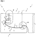
- FIG. 1 shows an embodiment of a panel according to the invention.
- the panel is shown split to show its opposite panel edges 1 and 1' and their complementary locking means 2 and 3 in the locked condition.
- the panel edges shown in sections can also be interpreted as a representation of two panels which are not severed.
- the design according to the invention is preferably intended to enable the panels to be designed with a small overall thickness.
- the low overall thickness should be possible even if the panel core is made of a carrier material that is brittle.
- the panel according to 1 consequently has a panel core 4 made of a carrier material which has a plastic as the matrix material.
- a proportion of solid material is provided therein as a filler, namely a mineral filler in the form of talc.
- This carrier material has a certain brittleness due to the filler.
- Basically it is about 1 to a panel with a panel top 5 with a wear layer 6, a panel bottom 7 and with pairs of opposite panel edges 1 and 1 ', which form a pair of edges.
- the pair of edges shown has complementary locking means 2 or 3 with a tongue and groove profile, namely a locking groove 8 on a groove side of the pair of edges and a locking spring 9 on a tongue side of the pair of edges two panels perpendicular to the interlocked panel edges and away from each other.
- the panel edges have a positive locking effect in the vertical direction.
- the panel On the groove side, the panel has an upper groove wall 10 and a lower groove wall 11 .
- the upper groove wall has a free end on which a flat abutment surface 12 is formed.
- the abutment surface 12 is arranged perpendicular to the panel plane.
- the lower groove wall 11 is longer than the upper groove wall. It protrudes further in the distal direction than the upper groove wall.
- At its free end it is provided with an edge strip 13 which has a holding surface 14 which is arranged in the proximal direction, i.e. its surface normal is aligned proximally.
- the panel On the spring side, the panel has the locking spring 9 and above it a counter-abutment surface 15 which interacts with the upper groove wall 10, namely touches its abutment surface 12 when the panel edges 1 and 1' are in the locked state.
- the locking spring 7 has a spring top 16 with a contact surface 17 which is directed toward the panel top 5 .
- the contact surface 17 is arranged parallel to the top side 5 of the panel.
- a rounding 18 follows the contact surface 17 .
- the rounding has a radius 20 which is larger than the distal extension 21 of the contact surface 17.
- the free end of the locking spring 9 is provided with a comparatively large rounding 18 and is thereby more stable than known panels which are more pointed or have corners .
- the carrier material holds together better at the free end of the locking spring 9 .
- the contours are made by machining, for example milled.
- the locking groove 8 has a contact surface 22 on the upper groove wall 10, which is arranged parallel to the contact surface 17 and according to FIG 1 at this.
- the contact surface 22 transitions into a groove base 23 which has a radius 24 and is adapted to the curve 18 of the locking spring 9, so that the curve 18 fits into the locking groove 8 and between the curve 15 and the radius 24 of the groove base 23 there is a small gap remains, which is in the order of tenths of a millimeter or fractions thereof.
- the large rounding 18 at the front of the locking spring 9 transitions into an outwardly curved (convex) contour 25 which forms the underside 26 of the spring.
- the convex contour 25 lies on a large radius 27, the center of which is well above the panel. The radius 27 is several times larger than the overall thickness T of the panel.
- the contour 25 of the underside 26 of the spring that is curved in this way extends far in the proximal direction.
- the contour 25 transitions into a counter-retaining surface 29.
- the counter-retaining surface has a surface normal in the proximal direction. In the locked state, the counter-retaining surface 29 interacts with the above-mentioned retaining surface 14 of the edge strip 13 of the lower groove wall 11.
- the holding surface 14 and the counter-holding surface 29 are parallel to one another and touch one another. Furthermore, this surface pairing of holding surface/counter-holding surface is inclined relative to the perpendicular L of the top side of the panel 5, the angle of inclination ⁇ relative to the perpendicular being marked with +/- within the meaning of the invention. In the present case, the angle of inclination ⁇ is +5° according to this definition.
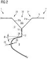
- an alternative design for the cutout is shown in 1 is marked with II.
- a section of the locking groove 8 and a section of the locking spring 9, which are in the locked state, can be seen.
- an edge break 29 or 30 is provided in the form of a 45° chamfer 29a and 30a.
- the 45° bevels form a free space 31 in the form of a V-joint 31a.
- the depth of the V-joint 31a, or the depth of the chamfer is 19% of the total thickness T of the panel.
- a contact surface 28 which is inclined relative to the horizontal by an angle of inclination ⁇ .
- the angle of inclination ⁇ has an amount of 8° here, so that the contact surface 28 runs downwards towards the rounding 18 .
- the upper groove wall 10 is shown, which has an abutment surface 12 at its free end.
- the abutment surface 12 is arranged perpendicularly (vertically) to the top side 5 of the panel. Due to the edge break 29 located above, the abutment surface 12 is somewhat smaller than in the exemplary embodiment of FIG 1 .
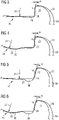
- FIGS. 3 to 10 show alternative designs for the area in 1 is marked with III. Each of these alternatives can be used both as a modification of 1 provide, as well as use together with the modification in 2 has already been suggested.
- Area III is about the lower groove wall 11 of the locking groove 8, which is provided with the edge strip 13, and the matching contour 25 of the spring underside 26 locking spring 9.
- FIG 3 shows a section of the lower groove wall 11 with the edge strip 13, which has a proximally arranged holding surface 14, which means that the surface normal of the holding surface 14 is aligned proximally.
- the holding surface is inclined by +5° relative to the perpendicular L on the top side of the panel.
- This embodiment provides positive locking against moving apart of the locked panel edges in a direction that is in the plane of the locked panels and at the same time perpendicular to the locked panel edges.
- a locking effect against the locked panel edges moving apart perpendicular to the panel plane (vertical) is according to FIG 3 not provided.
- the contour 25 of the spring underside 26 curves outwards (convex), the curve having a large radius 27 that appears almost straight in the illustration.
- the contour 25 of the spring underside 26 merges into a counter-retaining surface 29 which is inclined to match the retaining surface 14 of the edge strip 13 .
- the support surface/countersurface mating is parallel and in contact with each other.
- the transition between the curved contour 25 of the spring underside 26 and the counter-retaining surface 29 is provided as a tangential transition with a small radius 32 .
- the edge strip 13 is bent downwards in the distal direction.
- the locking spring 9 has a recess 33 which is larger than the edge strip 13.
- a gap 34 air is provided between the edge strip 13 and the recess 33 in the distal direction.
- the contour of the recess 33 is also curved to match the edge strip 13 .
- an alternative design is shown, based on 3 based to which reference is made. It differs in a modified contour 25 of the outwardly curved spring underside 26 and the matching contour of the lower groove wall 11.
- the lower groove wall 11 namely has a low point 35 and from there a certain (slight) rise in the distal direction.
- This configuration is preferred when a contact surface at the top of the locking spring 9 has a slope, as in the example of FIG 2 the contact surface 28, whereby it is on the in 2 planned edge breaking does not arrive.
- the mentioned rise in the contour of the lower groove wall 11 can cause the locking spring 9 to slide up along the rise.
- the contact surface 28 provided at the top of the locking spring 9 can slide along a complementary contact surface 22 of the upper groove wall 10 because this has an inclination angle ⁇ which is approximately parallel to the slope of the contour of the lower groove wall 11.
- the embodiment of figure 5 based on that of 3 .
- the lower groove wall 11 has a recess 36 at the transition to the edge strip 13, which merges into the holding surface 14 of the edge strip 13.
- the recess 36 is groove-shaped with a round cross-section, which serves for stability.
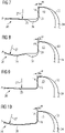
- FIG. 6 is an alternative design based on figure 5 based to which reference is made. It differs in a modified contour 25 of the outwardly curved underside of the tongue 26 and the matching contour of the lower groove wall 11. These contours are designed as described above in 4 , ie the lower groove wall 11 has a low point 35 . From the low point 35 in the distal direction, a certain (slight) increase towards the edge strip 13 is provided.
- This design is preferred in combination with one, as in the example 2 , inclined contact surface 28 on the spring top 16 of the locking spring 9, for the same reasons as mentioned above.
- the embodiment of 7 based on that of figure 5 . It differs in the design of the wheel bar 13, which now has a proximal holding surface 14, which is again inclined relative to the perpendicular L of the panel top 5, but compared to figure 5 in the opposite direction, which means an angle of inclination ⁇ of -5° in the present exemplary embodiment.
- the locking spring 9 has a proximal counter-retaining surface 29 which, in the locked state, is arranged parallel to the retaining surface 14 of the edge strip 13 and touches it over an area.
- the pairing of retaining surface/counter-retaining surface is arranged with an angle of inclination ⁇ of -5°, then there is an additional undercut between the two surfaces of this pairing, which also causes locking in a direction perpendicular to the panel plane (vertical). In order to bring this undercut into engagement, a certain elastic deformation in the area of the locking means 2 and 3 is necessary during the joining process.
- the holding surface / counter holding surface identical with 7 are arranged at an angle of inclination ⁇ of -5°, so that they can cause locking perpendicular to the panel level (vertical).
- the contour 25 of the outwardly curved underside of the tongue 26 and the matching contour of the lower groove wall 11 have been modified, as described above in Figures 4 and 5 ie the lower groove wall 11 has a low point 35 and from there in the distal direction towards the edge strip 13 there is a certain (slight) rise.
- This design is in turn preferred in combination with an inclined contact surface on the upper side of the locking spring, as in the example of FIG 2 the contact surface 28.
- the lower groove wall 11 is provided with a groove-shaped depression 36, as in FIG figure 5 , to which reference is made.
- 9 is an embodiment whose holding surface / counter holding surface is identical to 7 are arranged at an angle of inclination ⁇ of -5°, so that they can cause locking perpendicular to the panel plane (vertical). In contrast to 7 however, a groove-shaped depression 36 in the lower groove wall 11 is dispensed with.
- 10 is a further exemplary embodiment with a holding surface/counterholding surface arranged at an angle of inclination ⁇ of -5°, so that they cause locking perpendicular to the panel plane (vertical), insofar as it is 10 identical with figs 7, 8 and 9 .
- the contour 25 of the outwardly curved spring underside 26 and the matching contour of the lower groove wall 11, which has a low point 35 and from there a certain (slight) rise in the distal direction towards the edge strip 13, differ.
Priority Applications (13)
| Application Number | Priority Date | Filing Date | Title |
|---|---|---|---|
| PL18178061.0T PL3581731T3 (pl) | 2018-06-15 | 2018-06-15 | Panel |
| ES18178061T ES2934795T3 (es) | 2018-06-15 | 2018-06-15 | Panel |
| EP18178061.0A EP3581731B1 (de) | 2018-06-15 | 2018-06-15 | Paneel |
| PT181780610T PT3581731T (pt) | 2018-06-15 | 2018-06-15 | Painel |
| CA3103688A CA3103688C (en) | 2018-06-15 | 2019-06-13 | Panel |
| BR112020022916-4A BR112020022916A2 (pt) | 2018-06-15 | 2019-06-13 | painel |
| PCT/EP2019/065463 WO2019238810A1 (de) | 2018-06-15 | 2019-06-13 | Paneel |
| KR1020217001271A KR102501628B1 (ko) | 2018-06-15 | 2019-06-13 | 패널 |
| MX2020013482A MX2020013482A (es) | 2018-06-15 | 2019-06-13 | Panel. |
| RU2020137425A RU2754246C1 (ru) | 2018-06-15 | 2019-06-13 | Панель |
| CN201980040300.3A CN112334624A (zh) | 2018-06-15 | 2019-06-13 | 嵌板 |
| US17/252,536 US11591805B2 (en) | 2018-06-15 | 2019-06-13 | Panel |
| US18/081,069 US20230116585A1 (en) | 2018-06-15 | 2022-12-14 | Panel |
Applications Claiming Priority (1)
| Application Number | Priority Date | Filing Date | Title |
|---|---|---|---|
| EP18178061.0A EP3581731B1 (de) | 2018-06-15 | 2018-06-15 | Paneel |
Publications (2)
| Publication Number | Publication Date |
|---|---|
| EP3581731A1 EP3581731A1 (de) | 2019-12-18 |
| EP3581731B1 true EP3581731B1 (de) | 2022-11-30 |
Family
ID=62705406
Family Applications (1)
| Application Number | Title | Priority Date | Filing Date |
|---|---|---|---|
| EP18178061.0A Active EP3581731B1 (de) | 2018-06-15 | 2018-06-15 | Paneel |
Country Status (12)
| Country | Link |
|---|---|
| US (2) | US11591805B2 (pl) |
| EP (1) | EP3581731B1 (pl) |
| KR (1) | KR102501628B1 (pl) |
| CN (1) | CN112334624A (pl) |
| BR (1) | BR112020022916A2 (pl) |
| CA (1) | CA3103688C (pl) |
| ES (1) | ES2934795T3 (pl) |
| MX (1) | MX2020013482A (pl) |
| PL (1) | PL3581731T3 (pl) |
| PT (1) | PT3581731T (pl) |
| RU (1) | RU2754246C1 (pl) |
| WO (1) | WO2019238810A1 (pl) |
Families Citing this family (2)
| Publication number | Priority date | Publication date | Assignee | Title |
|---|---|---|---|---|
| NL2019609B1 (en) * | 2017-09-22 | 2019-03-28 | Innovations4Flooring Holding N V | Panel and covering |
| CN113833228B (zh) * | 2021-09-29 | 2023-03-10 | 中山市大自然格瑞新型材料有限公司 | 一种地板锁扣及地板 |
Citations (7)
| Publication number | Priority date | Publication date | Assignee | Title |
|---|---|---|---|---|
| WO2007028560A1 (de) | 2005-09-07 | 2007-03-15 | Tilo Gmbh | Paneel zum mechanischen verbinden mit einem weiteren paneel durch verschwenken |
| WO2012142986A1 (de) | 2011-04-18 | 2012-10-26 | Guido Schulte | Fussbodenelement |
| WO2013179260A1 (en) | 2012-06-01 | 2013-12-05 | Unilin, Bvba | Panel for forming a floor covering, method for manufacturing such panels and granulate applied herewith. |
| EP2977525A1 (fr) | 2014-07-21 | 2016-01-27 | Jean-Louis Lefort | Lame de parquet, ensemble d'au moins deux telles lames et procédé d'assemblage associé |
| WO2016050848A1 (de) | 2014-09-30 | 2016-04-07 | Akzenta Paneele + Profile Gmbh | Paneel |
| CN107060269A (zh) | 2017-05-15 | 2017-08-18 | 翟华鑫 | 一种多功能复合结构远红外线发热瓷砖 |
| WO2018017637A1 (en) | 2016-07-19 | 2018-01-25 | Microchip Technology Incorporated | Time-based delay line analog comparator |
Family Cites Families (23)
| Publication number | Priority date | Publication date | Assignee | Title |
|---|---|---|---|---|
| BE1010487A6 (nl) * | 1996-06-11 | 1998-10-06 | Unilin Beheer Bv | Vloerbekleding bestaande uit harde vloerpanelen en werkwijze voor het vervaardigen van dergelijke vloerpanelen. |
| SE517478C2 (sv) * | 1999-04-30 | 2002-06-11 | Valinge Aluminium Ab | Låssystem för mekanisk hofogning av golvskivor, golvskiva försedd med låssystemet samt metod för framställning av mekaniskt hopfogningsbara golvskivor |
| BE1013553A3 (nl) * | 2000-06-13 | 2002-03-05 | Unilin Beheer Bv | Vloerbekleding. |
| US6851241B2 (en) * | 2001-01-12 | 2005-02-08 | Valinge Aluminium Ab | Floorboards and methods for production and installation thereof |
| EP1852563B1 (en) * | 2001-01-12 | 2013-07-31 | Välinge Innovation AB | Flooring system comprising mechanically joinable floorboards |
| DE10112958B4 (de) | 2001-03-17 | 2005-06-30 | Kronotec Ag | Fussbodenpaneel |
| DE20220655U1 (de) * | 2002-04-04 | 2004-01-08 | Akzenta Paneele + Profile Gmbh | Paneel sowie Verriegelungssystem für Paneele |
| DE10252864A1 (de) * | 2002-05-31 | 2004-05-27 | Kronotec Ag | Fussbodenpaneel |
| ES2297074T3 (es) | 2002-05-31 | 2008-05-01 | Flooring Technologies Ltd. | Panel de suelo y procedimiento para realizar la instalacion de este panel. |
| AT414251B (de) * | 2002-06-19 | 2006-10-15 | Weitzer Parkett Gmbh & Co Kg | Paneelelement sowie verbindungssystem für paneelelemente |
| US7617651B2 (en) * | 2002-11-12 | 2009-11-17 | Kronotec Ag | Floor panel |
| AU2004320336B2 (en) * | 2004-05-26 | 2008-10-02 | Fritz Egger Gmbh & Co. | Panel, particularly floor panel |
| CN2801951Y (zh) | 2005-06-21 | 2006-08-02 | 深圳市燕加隆实业发展有限公司 | 侧面设有圆弧锁扣的地板 |
| CN201671292U (zh) | 2010-05-10 | 2010-12-15 | 德尔国际地板有限公司 | 一种仿实木模压地板 |
| US20150218812A1 (en) * | 2012-09-19 | 2015-08-06 | Inotec Global Limited | Panel for Covering a Surface or Support and an Associated Joint System |
| DE102013113109A1 (de) * | 2013-11-27 | 2015-06-11 | Guido Schulte | Fußbodendiele |
| DE102013113478A1 (de) * | 2013-12-04 | 2015-06-11 | Guido Schulte | Fußboden-, Wand- oder Deckenpaneel und Verfahren zu dessen Herstellung |
| EP3087280B1 (en) | 2013-12-27 | 2019-07-10 | McGard LLC | Fastener with protected decorative cap |
| US10876301B2 (en) * | 2014-09-30 | 2020-12-29 | Akzenta Paneele + Profile Gmbh | Panel with complimentary locking elements |
| BE1024723B1 (nl) * | 2016-11-10 | 2018-06-11 | Ivc Bvba | Vloerpaneel en werkwijze voor het vervaardigen van een vloerpaneel. |
| US11015351B2 (en) * | 2017-03-21 | 2021-05-25 | Flooring Industries Limited, Sarl | Floor panel for forming a floor covering |
| NL2019609B1 (en) * | 2017-09-22 | 2019-03-28 | Innovations4Flooring Holding N V | Panel and covering |
| EP3524750A1 (de) * | 2018-02-07 | 2019-08-14 | Akzenta Paneele + Profile GmbH | Paneel |
-
2018
- 2018-06-15 PL PL18178061.0T patent/PL3581731T3/pl unknown
- 2018-06-15 ES ES18178061T patent/ES2934795T3/es active Active
- 2018-06-15 EP EP18178061.0A patent/EP3581731B1/de active Active
- 2018-06-15 PT PT181780610T patent/PT3581731T/pt unknown
-
2019
- 2019-06-13 MX MX2020013482A patent/MX2020013482A/es unknown
- 2019-06-13 WO PCT/EP2019/065463 patent/WO2019238810A1/de active Application Filing
- 2019-06-13 RU RU2020137425A patent/RU2754246C1/ru active
- 2019-06-13 CN CN201980040300.3A patent/CN112334624A/zh active Pending
- 2019-06-13 KR KR1020217001271A patent/KR102501628B1/ko active IP Right Grant
- 2019-06-13 BR BR112020022916-4A patent/BR112020022916A2/pt active IP Right Grant
- 2019-06-13 CA CA3103688A patent/CA3103688C/en active Active
- 2019-06-13 US US17/252,536 patent/US11591805B2/en active Active
-
2022
- 2022-12-14 US US18/081,069 patent/US20230116585A1/en not_active Abandoned
Patent Citations (7)
| Publication number | Priority date | Publication date | Assignee | Title |
|---|---|---|---|---|
| WO2007028560A1 (de) | 2005-09-07 | 2007-03-15 | Tilo Gmbh | Paneel zum mechanischen verbinden mit einem weiteren paneel durch verschwenken |
| WO2012142986A1 (de) | 2011-04-18 | 2012-10-26 | Guido Schulte | Fussbodenelement |
| WO2013179260A1 (en) | 2012-06-01 | 2013-12-05 | Unilin, Bvba | Panel for forming a floor covering, method for manufacturing such panels and granulate applied herewith. |
| EP2977525A1 (fr) | 2014-07-21 | 2016-01-27 | Jean-Louis Lefort | Lame de parquet, ensemble d'au moins deux telles lames et procédé d'assemblage associé |
| WO2016050848A1 (de) | 2014-09-30 | 2016-04-07 | Akzenta Paneele + Profile Gmbh | Paneel |
| WO2018017637A1 (en) | 2016-07-19 | 2018-01-25 | Microchip Technology Incorporated | Time-based delay line analog comparator |
| CN107060269A (zh) | 2017-05-15 | 2017-08-18 | 翟华鑫 | 一种多功能复合结构远红外线发热瓷砖 |
Also Published As
| Publication number | Publication date |
|---|---|
| CA3103688A1 (en) | 2019-12-19 |
| BR112020022916A2 (pt) | 2021-02-23 |
| US20210115677A1 (en) | 2021-04-22 |
| CN112334624A (zh) | 2021-02-05 |
| KR102501628B1 (ko) | 2023-02-21 |
| EP3581731A1 (de) | 2019-12-18 |
| RU2754246C1 (ru) | 2021-08-31 |
| KR20210019549A (ko) | 2021-02-22 |
| ES2934795T3 (es) | 2023-02-27 |
| PL3581731T3 (pl) | 2023-04-11 |
| MX2020013482A (es) | 2021-02-26 |
| US11591805B2 (en) | 2023-02-28 |
| WO2019238810A1 (de) | 2019-12-19 |
| US20230116585A1 (en) | 2023-04-13 |
| PT3581731T (pt) | 2023-03-03 |
| CA3103688C (en) | 2023-04-18 |
Similar Documents
| Publication | Publication Date | Title |
|---|---|---|
| EP2057327B1 (de) | Paneel, insbesondere bodenpaneel | |
| EP2226447B1 (de) | Paneel, insbesondere Bodenpaneel | |
| EP1994241B1 (de) | Paneel, insbesondere bodenpaneel | |
| EP3031998B1 (de) | Paneel mit einem hakenförmigen Verriegelungssystem | |
| EP2795017B1 (de) | Paneel eines fussbodenbelags mit einer entlang einer seitenkante geneigten verriegelungsfläche | |
| EP1246981B1 (de) | Paneelelemente | |
| DE102009034903B3 (de) | Belag aus mechanisch miteinander verbindbaren Paneelen | |
| EP1128000B1 (de) | Paneel, insbesondere Fussbodenpaneel | |
| EP3489431B1 (de) | Paneel | |
| EP3877610B1 (de) | Paneel | |
| DE20220655U1 (de) | Paneel sowie Verriegelungssystem für Paneele | |
| EP3581731B1 (de) | Paneel | |
| DE102009019492A1 (de) | Verriegelungssystem für Paneele | |
| EP3708739A1 (de) | Hartes fussbodenpaneel zur schwimmenden verlegung unter ausbildung eines fussbodenpaneelverbundes | |
| DE102013018887B4 (de) | Laufschienenanordnung | |
| EP0187294A2 (de) | Pflasterstein | |
| DE10021993B4 (de) | Rinnenschuss für Kettenkratzförderer | |
| DE102005039369A1 (de) | Lösbar aneinander zu befestigende, flächige Bauteile, insbesondere Bodenbelagsteile | |
| WO2021064133A1 (de) | Pflasterstein aus beton, pflasterverband und verfahren zum herstellen eines pflastersteins | |
| EP3080365B1 (de) | Paneel mit verriegelungselement | |
| EP2998421B1 (de) | Webschaftkupplung und Webschaft, der eine solche aufweist | |
| EP3971365A1 (de) | Paneel | |
| DE19901968A1 (de) | Stein | |
| DE102008004108A1 (de) | Paneel für einen Boden-, Wand- und/oder Deckenbelag sowie Verfahren zu dessen Herstellung | |
| DE102004049352A1 (de) | Verbindung für Fußbodenpaneele II |
Legal Events
| Date | Code | Title | Description |
|---|---|---|---|
| PUAI | Public reference made under article 153(3) epc to a published international application that has entered the european phase |
Free format text: ORIGINAL CODE: 0009012 |
|
| STAA | Information on the status of an ep patent application or granted ep patent |
Free format text: STATUS: THE APPLICATION HAS BEEN PUBLISHED |
|
| AK | Designated contracting states |
Kind code of ref document: A1 Designated state(s): AL AT BE BG CH CY CZ DE DK EE ES FI FR GB GR HR HU IE IS IT LI LT LU LV MC MK MT NL NO PL PT RO RS SE SI SK SM TR |
|
| AX | Request for extension of the european patent |
Extension state: BA ME |
|
| STAA | Information on the status of an ep patent application or granted ep patent |
Free format text: STATUS: REQUEST FOR EXAMINATION WAS MADE |
|
| 17P | Request for examination filed |
Effective date: 20200515 |
|
| RBV | Designated contracting states (corrected) |
Designated state(s): AL AT BE BG CH CY CZ DE DK EE ES FI FR GB GR HR HU IE IS IT LI LT LU LV MC MK MT NL NO PL PT RO RS SE SI SK SM TR |
|
| GRAP | Despatch of communication of intention to grant a patent |
Free format text: ORIGINAL CODE: EPIDOSNIGR1 |
|
| STAA | Information on the status of an ep patent application or granted ep patent |
Free format text: STATUS: GRANT OF PATENT IS INTENDED |
|
| INTG | Intention to grant announced |
Effective date: 20220520 |
|
| GRAS | Grant fee paid |
Free format text: ORIGINAL CODE: EPIDOSNIGR3 |
|
| GRAJ | Information related to disapproval of communication of intention to grant by the applicant or resumption of examination proceedings by the epo deleted |
Free format text: ORIGINAL CODE: EPIDOSDIGR1 |
|
| GRAL | Information related to payment of fee for publishing/printing deleted |
Free format text: ORIGINAL CODE: EPIDOSDIGR3 |
|
| STAA | Information on the status of an ep patent application or granted ep patent |
Free format text: STATUS: REQUEST FOR EXAMINATION WAS MADE |
|
| INTC | Intention to grant announced (deleted) | ||
| GRAP | Despatch of communication of intention to grant a patent |
Free format text: ORIGINAL CODE: EPIDOSNIGR1 |
|
| STAA | Information on the status of an ep patent application or granted ep patent |
Free format text: STATUS: GRANT OF PATENT IS INTENDED |
|
| GRAA | (expected) grant |
Free format text: ORIGINAL CODE: 0009210 |
|
| STAA | Information on the status of an ep patent application or granted ep patent |
Free format text: STATUS: THE PATENT HAS BEEN GRANTED |
|
| INTG | Intention to grant announced |
Effective date: 20221014 |
|
| AK | Designated contracting states |
Kind code of ref document: B1 Designated state(s): AL AT BE BG CH CY CZ DE DK EE ES FI FR GB GR HR HU IE IS IT LI LT LU LV MC MK MT NL NO PL PT RO RS SE SI SK SM TR |
|
| REG | Reference to a national code |
Ref country code: CH Ref legal event code: EP Ref country code: GB Ref legal event code: FG4D Free format text: NOT ENGLISH |
|
| REG | Reference to a national code |
Ref country code: AT Ref legal event code: REF Ref document number: 1534797 Country of ref document: AT Kind code of ref document: T Effective date: 20221215 Ref country code: DE Ref legal event code: R096 Ref document number: 502018011125 Country of ref document: DE |
|
| REG | Reference to a national code |
Ref country code: IE Ref legal event code: FG4D Free format text: LANGUAGE OF EP DOCUMENT: GERMAN |
|
| REG | Reference to a national code |
Ref country code: ES Ref legal event code: FG2A Ref document number: 2934795 Country of ref document: ES Kind code of ref document: T3 Effective date: 20230227 |
|
| REG | Reference to a national code |
Ref country code: NL Ref legal event code: FP |
|
| REG | Reference to a national code |
Ref country code: PT Ref legal event code: SC4A Ref document number: 3581731 Country of ref document: PT Date of ref document: 20230303 Kind code of ref document: T Free format text: AVAILABILITY OF NATIONAL TRANSLATION Effective date: 20230227 |
|
| REG | Reference to a national code |
Ref country code: LT Ref legal event code: MG9D |
|
| PG25 | Lapsed in a contracting state [announced via postgrant information from national office to epo] |
Ref country code: SE Free format text: LAPSE BECAUSE OF FAILURE TO SUBMIT A TRANSLATION OF THE DESCRIPTION OR TO PAY THE FEE WITHIN THE PRESCRIBED TIME-LIMIT Effective date: 20221130 Ref country code: NO Free format text: LAPSE BECAUSE OF FAILURE TO SUBMIT A TRANSLATION OF THE DESCRIPTION OR TO PAY THE FEE WITHIN THE PRESCRIBED TIME-LIMIT Effective date: 20230228 Ref country code: LT Free format text: LAPSE BECAUSE OF FAILURE TO SUBMIT A TRANSLATION OF THE DESCRIPTION OR TO PAY THE FEE WITHIN THE PRESCRIBED TIME-LIMIT Effective date: 20221130 Ref country code: FI Free format text: LAPSE BECAUSE OF FAILURE TO SUBMIT A TRANSLATION OF THE DESCRIPTION OR TO PAY THE FEE WITHIN THE PRESCRIBED TIME-LIMIT Effective date: 20221130 |
|
| PG25 | Lapsed in a contracting state [announced via postgrant information from national office to epo] |
Ref country code: RS Free format text: LAPSE BECAUSE OF FAILURE TO SUBMIT A TRANSLATION OF THE DESCRIPTION OR TO PAY THE FEE WITHIN THE PRESCRIBED TIME-LIMIT Effective date: 20221130 Ref country code: LV Free format text: LAPSE BECAUSE OF FAILURE TO SUBMIT A TRANSLATION OF THE DESCRIPTION OR TO PAY THE FEE WITHIN THE PRESCRIBED TIME-LIMIT Effective date: 20221130 Ref country code: IS Free format text: LAPSE BECAUSE OF FAILURE TO SUBMIT A TRANSLATION OF THE DESCRIPTION OR TO PAY THE FEE WITHIN THE PRESCRIBED TIME-LIMIT Effective date: 20230330 Ref country code: HR Free format text: LAPSE BECAUSE OF FAILURE TO SUBMIT A TRANSLATION OF THE DESCRIPTION OR TO PAY THE FEE WITHIN THE PRESCRIBED TIME-LIMIT Effective date: 20221130 Ref country code: GR Free format text: LAPSE BECAUSE OF FAILURE TO SUBMIT A TRANSLATION OF THE DESCRIPTION OR TO PAY THE FEE WITHIN THE PRESCRIBED TIME-LIMIT Effective date: 20230301 |
|
| P01 | Opt-out of the competence of the unified patent court (upc) registered |
Effective date: 20230526 |
|
| PG25 | Lapsed in a contracting state [announced via postgrant information from national office to epo] |
Ref country code: SM Free format text: LAPSE BECAUSE OF FAILURE TO SUBMIT A TRANSLATION OF THE DESCRIPTION OR TO PAY THE FEE WITHIN THE PRESCRIBED TIME-LIMIT Effective date: 20221130 Ref country code: RO Free format text: LAPSE BECAUSE OF FAILURE TO SUBMIT A TRANSLATION OF THE DESCRIPTION OR TO PAY THE FEE WITHIN THE PRESCRIBED TIME-LIMIT Effective date: 20221130 Ref country code: EE Free format text: LAPSE BECAUSE OF FAILURE TO SUBMIT A TRANSLATION OF THE DESCRIPTION OR TO PAY THE FEE WITHIN THE PRESCRIBED TIME-LIMIT Effective date: 20221130 Ref country code: DK Free format text: LAPSE BECAUSE OF FAILURE TO SUBMIT A TRANSLATION OF THE DESCRIPTION OR TO PAY THE FEE WITHIN THE PRESCRIBED TIME-LIMIT Effective date: 20221130 |
|
| PGFP | Annual fee paid to national office [announced via postgrant information from national office to epo] |
Ref country code: PT Payment date: 20230602 Year of fee payment: 6 Ref country code: NL Payment date: 20230620 Year of fee payment: 6 Ref country code: FR Payment date: 20230622 Year of fee payment: 6 Ref country code: CZ Payment date: 20230602 Year of fee payment: 6 |
|
| REG | Reference to a national code |
Ref country code: DE Ref legal event code: R026 Ref document number: 502018011125 Country of ref document: DE |
|
| PG25 | Lapsed in a contracting state [announced via postgrant information from national office to epo] |
Ref country code: SK Free format text: LAPSE BECAUSE OF FAILURE TO SUBMIT A TRANSLATION OF THE DESCRIPTION OR TO PAY THE FEE WITHIN THE PRESCRIBED TIME-LIMIT Effective date: 20221130 Ref country code: AL Free format text: LAPSE BECAUSE OF FAILURE TO SUBMIT A TRANSLATION OF THE DESCRIPTION OR TO PAY THE FEE WITHIN THE PRESCRIBED TIME-LIMIT Effective date: 20221130 |
|
| PGFP | Annual fee paid to national office [announced via postgrant information from national office to epo] |
Ref country code: TR Payment date: 20230609 Year of fee payment: 6 Ref country code: PL Payment date: 20230602 Year of fee payment: 6 Ref country code: AT Payment date: 20230616 Year of fee payment: 6 |
|
| PLBI | Opposition filed |
Free format text: ORIGINAL CODE: 0009260 |
|
| PLAX | Notice of opposition and request to file observation + time limit sent |
Free format text: ORIGINAL CODE: EPIDOSNOBS2 |
|
| PGFP | Annual fee paid to national office [announced via postgrant information from national office to epo] |
Ref country code: BE Payment date: 20230619 Year of fee payment: 6 |
|
| 26 | Opposition filed |
Opponent name: LIGNUM TECHNOLOGIES AG Effective date: 20230824 |
|
| PGFP | Annual fee paid to national office [announced via postgrant information from national office to epo] |
Ref country code: IT Payment date: 20230630 Year of fee payment: 6 Ref country code: GB Payment date: 20230622 Year of fee payment: 6 Ref country code: ES Payment date: 20230719 Year of fee payment: 6 Ref country code: CH Payment date: 20230702 Year of fee payment: 6 |
|
| PG25 | Lapsed in a contracting state [announced via postgrant information from national office to epo] |
Ref country code: SI Free format text: LAPSE BECAUSE OF FAILURE TO SUBMIT A TRANSLATION OF THE DESCRIPTION OR TO PAY THE FEE WITHIN THE PRESCRIBED TIME-LIMIT Effective date: 20221130 |
|
| PGFP | Annual fee paid to national office [announced via postgrant information from national office to epo] |
Ref country code: DE Payment date: 20230828 Year of fee payment: 6 |
|
| PG25 | Lapsed in a contracting state [announced via postgrant information from national office to epo] |
Ref country code: MC Free format text: LAPSE BECAUSE OF FAILURE TO SUBMIT A TRANSLATION OF THE DESCRIPTION OR TO PAY THE FEE WITHIN THE PRESCRIBED TIME-LIMIT Effective date: 20221130 |
|
| PLBB | Reply of patent proprietor to notice(s) of opposition received |
Free format text: ORIGINAL CODE: EPIDOSNOBS3 |
|
| PG25 | Lapsed in a contracting state [announced via postgrant information from national office to epo] |
Ref country code: MC Free format text: LAPSE BECAUSE OF FAILURE TO SUBMIT A TRANSLATION OF THE DESCRIPTION OR TO PAY THE FEE WITHIN THE PRESCRIBED TIME-LIMIT Effective date: 20221130 |
|
| PG25 | Lapsed in a contracting state [announced via postgrant information from national office to epo] |
Ref country code: LU Free format text: LAPSE BECAUSE OF NON-PAYMENT OF DUE FEES Effective date: 20230615 |
|
| REG | Reference to a national code |
Ref country code: IE Ref legal event code: MM4A |
|
| PG25 | Lapsed in a contracting state [announced via postgrant information from national office to epo] |
Ref country code: LU Free format text: LAPSE BECAUSE OF NON-PAYMENT OF DUE FEES Effective date: 20230615 |
|
| PG25 | Lapsed in a contracting state [announced via postgrant information from national office to epo] |
Ref country code: IE Free format text: LAPSE BECAUSE OF NON-PAYMENT OF DUE FEES Effective date: 20230615 |
|
| PG25 | Lapsed in a contracting state [announced via postgrant information from national office to epo] |
Ref country code: IE Free format text: LAPSE BECAUSE OF NON-PAYMENT OF DUE FEES Effective date: 20230615 |