EP3581275B1 - Assemblage de coupleur de pointe de pipette et pointe de pipette - Google Patents
Assemblage de coupleur de pointe de pipette et pointe de pipette Download PDFInfo
- Publication number
- EP3581275B1 EP3581275B1 EP19187501.2A EP19187501A EP3581275B1 EP 3581275 B1 EP3581275 B1 EP 3581275B1 EP 19187501 A EP19187501 A EP 19187501A EP 3581275 B1 EP3581275 B1 EP 3581275B1
- Authority
- EP
- European Patent Office
- Prior art keywords
- pipette tip
- annular
- coupling device
- distal
- section
- Prior art date
- Legal status (The legal status is an assumption and is not a legal conclusion. Google has not performed a legal analysis and makes no representation as to the accuracy of the status listed.)
- Active
Links
- 230000008878 coupling Effects 0.000 title claims description 166
- 238000010168 coupling process Methods 0.000 title claims description 166
- 238000005859 coupling reaction Methods 0.000 title claims description 166
- 238000007789 sealing Methods 0.000 claims description 87
- 125000006850 spacer group Chemical group 0.000 claims description 13
- 239000004020 conductor Substances 0.000 claims description 8
- 241000013987 Colletes Species 0.000 claims 5
- 239000007788 liquid Substances 0.000 description 31
- 238000000034 method Methods 0.000 description 30
- 230000008569 process Effects 0.000 description 22
- 230000007704 transition Effects 0.000 description 20
- 238000004891 communication Methods 0.000 description 8
- 238000013519 translation Methods 0.000 description 8
- 239000000463 material Substances 0.000 description 7
- 230000001154 acute effect Effects 0.000 description 6
- 238000001514 detection method Methods 0.000 description 6
- 238000012545 processing Methods 0.000 description 5
- 230000007423 decrease Effects 0.000 description 4
- 230000006870 function Effects 0.000 description 4
- 238000005452 bending Methods 0.000 description 3
- 230000008901 benefit Effects 0.000 description 3
- 230000000295 complement effect Effects 0.000 description 3
- 230000009977 dual effect Effects 0.000 description 3
- 230000008685 targeting Effects 0.000 description 3
- 238000012546 transfer Methods 0.000 description 3
- 238000000429 assembly Methods 0.000 description 2
- 230000000712 assembly Effects 0.000 description 2
- 230000006835 compression Effects 0.000 description 2
- 238000007906 compression Methods 0.000 description 2
- 230000003247 decreasing effect Effects 0.000 description 2
- 238000013461 design Methods 0.000 description 2
- 238000010586 diagram Methods 0.000 description 2
- 238000006073 displacement reaction Methods 0.000 description 2
- 239000013536 elastomeric material Substances 0.000 description 2
- 238000007654 immersion Methods 0.000 description 2
- 238000012986 modification Methods 0.000 description 2
- 230000004048 modification Effects 0.000 description 2
- 230000036961 partial effect Effects 0.000 description 2
- 230000002093 peripheral effect Effects 0.000 description 2
- 238000005381 potential energy Methods 0.000 description 2
- 230000002441 reversible effect Effects 0.000 description 2
- 238000005299 abrasion Methods 0.000 description 1
- 230000009471 action Effects 0.000 description 1
- 230000006978 adaptation Effects 0.000 description 1
- 230000002411 adverse Effects 0.000 description 1
- 230000004323 axial length Effects 0.000 description 1
- 230000008859 change Effects 0.000 description 1
- 230000001010 compromised effect Effects 0.000 description 1
- 230000006735 deficit Effects 0.000 description 1
- 230000006866 deterioration Effects 0.000 description 1
- 238000002474 experimental method Methods 0.000 description 1
- 239000012634 fragment Substances 0.000 description 1
- 238000012423 maintenance Methods 0.000 description 1
- 230000013011 mating Effects 0.000 description 1
- 239000011159 matrix material Substances 0.000 description 1
- 230000007246 mechanism Effects 0.000 description 1
- 239000002699 waste material Substances 0.000 description 1
Images


Classifications
-
- B—PERFORMING OPERATIONS; TRANSPORTING
- B01—PHYSICAL OR CHEMICAL PROCESSES OR APPARATUS IN GENERAL
- B01L—CHEMICAL OR PHYSICAL LABORATORY APPARATUS FOR GENERAL USE
- B01L3/00—Containers or dishes for laboratory use, e.g. laboratory glassware; Droppers
- B01L3/02—Burettes; Pipettes
- B01L3/0275—Interchangeable or disposable dispensing tips
- B01L3/0279—Interchangeable or disposable dispensing tips co-operating with positive ejection means
-
- B—PERFORMING OPERATIONS; TRANSPORTING
- B01—PHYSICAL OR CHEMICAL PROCESSES OR APPARATUS IN GENERAL
- B01L—CHEMICAL OR PHYSICAL LABORATORY APPARATUS FOR GENERAL USE
- B01L3/00—Containers or dishes for laboratory use, e.g. laboratory glassware; Droppers
-
- B—PERFORMING OPERATIONS; TRANSPORTING
- B01—PHYSICAL OR CHEMICAL PROCESSES OR APPARATUS IN GENERAL
- B01L—CHEMICAL OR PHYSICAL LABORATORY APPARATUS FOR GENERAL USE
- B01L3/00—Containers or dishes for laboratory use, e.g. laboratory glassware; Droppers
- B01L3/02—Burettes; Pipettes
-
- B—PERFORMING OPERATIONS; TRANSPORTING
- B01—PHYSICAL OR CHEMICAL PROCESSES OR APPARATUS IN GENERAL
- B01L—CHEMICAL OR PHYSICAL LABORATORY APPARATUS FOR GENERAL USE
- B01L3/00—Containers or dishes for laboratory use, e.g. laboratory glassware; Droppers
- B01L3/02—Burettes; Pipettes
- B01L3/021—Pipettes, i.e. with only one conduit for withdrawing and redistributing liquids
- B01L3/0217—Pipettes, i.e. with only one conduit for withdrawing and redistributing liquids of the plunger pump type
-
- B—PERFORMING OPERATIONS; TRANSPORTING
- B01—PHYSICAL OR CHEMICAL PROCESSES OR APPARATUS IN GENERAL
- B01L—CHEMICAL OR PHYSICAL LABORATORY APPARATUS FOR GENERAL USE
- B01L3/00—Containers or dishes for laboratory use, e.g. laboratory glassware; Droppers
- B01L3/02—Burettes; Pipettes
- B01L3/0275—Interchangeable or disposable dispensing tips
-
- B—PERFORMING OPERATIONS; TRANSPORTING
- B01—PHYSICAL OR CHEMICAL PROCESSES OR APPARATUS IN GENERAL
- B01L—CHEMICAL OR PHYSICAL LABORATORY APPARATUS FOR GENERAL USE
- B01L3/00—Containers or dishes for laboratory use, e.g. laboratory glassware; Droppers
- B01L3/56—Labware specially adapted for transferring fluids
- B01L3/563—Joints or fittings ; Separable fluid transfer means to transfer fluids between at least two containers, e.g. connectors
-
- B—PERFORMING OPERATIONS; TRANSPORTING
- B01—PHYSICAL OR CHEMICAL PROCESSES OR APPARATUS IN GENERAL
- B01L—CHEMICAL OR PHYSICAL LABORATORY APPARATUS FOR GENERAL USE
- B01L9/00—Supporting devices; Holding devices
-
- B—PERFORMING OPERATIONS; TRANSPORTING
- B01—PHYSICAL OR CHEMICAL PROCESSES OR APPARATUS IN GENERAL
- B01L—CHEMICAL OR PHYSICAL LABORATORY APPARATUS FOR GENERAL USE
- B01L9/00—Supporting devices; Holding devices
- B01L9/54—Supports specially adapted for pipettes and burettes
- B01L9/543—Supports specially adapted for pipettes and burettes for disposable pipette tips, e.g. racks or cassettes
-
- G—PHYSICS
- G01—MEASURING; TESTING
- G01N—INVESTIGATING OR ANALYSING MATERIALS BY DETERMINING THEIR CHEMICAL OR PHYSICAL PROPERTIES
- G01N1/00—Sampling; Preparing specimens for investigation
-
- G—PHYSICS
- G01—MEASURING; TESTING
- G01N—INVESTIGATING OR ANALYSING MATERIALS BY DETERMINING THEIR CHEMICAL OR PHYSICAL PROPERTIES
- G01N1/00—Sampling; Preparing specimens for investigation
- G01N1/02—Devices for withdrawing samples
- G01N1/10—Devices for withdrawing samples in the liquid or fluent state
-
- G—PHYSICS
- G01—MEASURING; TESTING
- G01N—INVESTIGATING OR ANALYSING MATERIALS BY DETERMINING THEIR CHEMICAL OR PHYSICAL PROPERTIES
- G01N35/00—Automatic analysis not limited to methods or materials provided for in any single one of groups G01N1/00 - G01N33/00; Handling materials therefor
- G01N35/10—Devices for transferring samples or any liquids to, in, or from, the analysis apparatus, e.g. suction devices, injection devices
-
- B—PERFORMING OPERATIONS; TRANSPORTING
- B01—PHYSICAL OR CHEMICAL PROCESSES OR APPARATUS IN GENERAL
- B01L—CHEMICAL OR PHYSICAL LABORATORY APPARATUS FOR GENERAL USE
- B01L2200/00—Solutions for specific problems relating to chemical or physical laboratory apparatus
- B01L2200/02—Adapting objects or devices to another
- B01L2200/021—Adjust spacings in an array of wells, pipettes or holders, format transfer between arrays of different size or geometry
-
- B—PERFORMING OPERATIONS; TRANSPORTING
- B01—PHYSICAL OR CHEMICAL PROCESSES OR APPARATUS IN GENERAL
- B01L—CHEMICAL OR PHYSICAL LABORATORY APPARATUS FOR GENERAL USE
- B01L2200/00—Solutions for specific problems relating to chemical or physical laboratory apparatus
- B01L2200/02—Adapting objects or devices to another
- B01L2200/023—Adapting objects or devices to another adapted for different sizes of tubes, tips or container
-
- B—PERFORMING OPERATIONS; TRANSPORTING
- B01—PHYSICAL OR CHEMICAL PROCESSES OR APPARATUS IN GENERAL
- B01L—CHEMICAL OR PHYSICAL LABORATORY APPARATUS FOR GENERAL USE
- B01L2200/00—Solutions for specific problems relating to chemical or physical laboratory apparatus
- B01L2200/02—Adapting objects or devices to another
- B01L2200/025—Align devices or objects to ensure defined positions relative to each other
-
- B—PERFORMING OPERATIONS; TRANSPORTING
- B01—PHYSICAL OR CHEMICAL PROCESSES OR APPARATUS IN GENERAL
- B01L—CHEMICAL OR PHYSICAL LABORATORY APPARATUS FOR GENERAL USE
- B01L2200/00—Solutions for specific problems relating to chemical or physical laboratory apparatus
- B01L2200/02—Adapting objects or devices to another
- B01L2200/026—Fluid interfacing between devices or objects, e.g. connectors, inlet details
-
- B—PERFORMING OPERATIONS; TRANSPORTING
- B01—PHYSICAL OR CHEMICAL PROCESSES OR APPARATUS IN GENERAL
- B01L—CHEMICAL OR PHYSICAL LABORATORY APPARATUS FOR GENERAL USE
- B01L2200/00—Solutions for specific problems relating to chemical or physical laboratory apparatus
- B01L2200/04—Exchange or ejection of cartridges, containers or reservoirs
-
- B—PERFORMING OPERATIONS; TRANSPORTING
- B01—PHYSICAL OR CHEMICAL PROCESSES OR APPARATUS IN GENERAL
- B01L—CHEMICAL OR PHYSICAL LABORATORY APPARATUS FOR GENERAL USE
- B01L2200/00—Solutions for specific problems relating to chemical or physical laboratory apparatus
- B01L2200/06—Fluid handling related problems
- B01L2200/0689—Sealing
-
- B—PERFORMING OPERATIONS; TRANSPORTING
- B01—PHYSICAL OR CHEMICAL PROCESSES OR APPARATUS IN GENERAL
- B01L—CHEMICAL OR PHYSICAL LABORATORY APPARATUS FOR GENERAL USE
- B01L2300/00—Additional constructional details
- B01L2300/08—Geometry, shape and general structure
- B01L2300/0832—Geometry, shape and general structure cylindrical, tube shaped
-
- B—PERFORMING OPERATIONS; TRANSPORTING
- B01—PHYSICAL OR CHEMICAL PROCESSES OR APPARATUS IN GENERAL
- B01L—CHEMICAL OR PHYSICAL LABORATORY APPARATUS FOR GENERAL USE
- B01L2300/00—Additional constructional details
- B01L2300/12—Specific details about materials
- B01L2300/123—Flexible; Elastomeric
-
- G—PHYSICS
- G01—MEASURING; TESTING
- G01N—INVESTIGATING OR ANALYSING MATERIALS BY DETERMINING THEIR CHEMICAL OR PHYSICAL PROPERTIES
- G01N35/00—Automatic analysis not limited to methods or materials provided for in any single one of groups G01N1/00 - G01N33/00; Handling materials therefor
- G01N35/10—Devices for transferring samples or any liquids to, in, or from, the analysis apparatus, e.g. suction devices, injection devices
- G01N35/1009—Characterised by arrangements for controlling the aspiration or dispense of liquids
- G01N2035/1025—Fluid level sensing
-
- G—PHYSICS
- G01—MEASURING; TESTING
- G01N—INVESTIGATING OR ANALYSING MATERIALS BY DETERMINING THEIR CHEMICAL OR PHYSICAL PROPERTIES
- G01N35/00—Automatic analysis not limited to methods or materials provided for in any single one of groups G01N1/00 - G01N33/00; Handling materials therefor
- G01N35/10—Devices for transferring samples or any liquids to, in, or from, the analysis apparatus, e.g. suction devices, injection devices
- G01N2035/1027—General features of the devices
- G01N2035/103—General features of the devices using disposable tips
-
- G—PHYSICS
- G01—MEASURING; TESTING
- G01N—INVESTIGATING OR ANALYSING MATERIALS BY DETERMINING THEIR CHEMICAL OR PHYSICAL PROPERTIES
- G01N35/00—Automatic analysis not limited to methods or materials provided for in any single one of groups G01N1/00 - G01N33/00; Handling materials therefor
- G01N35/10—Devices for transferring samples or any liquids to, in, or from, the analysis apparatus, e.g. suction devices, injection devices
- G01N35/1009—Characterised by arrangements for controlling the aspiration or dispense of liquids
- G01N35/1011—Control of the position or alignment of the transfer device
Definitions
- This disclosure pertains generally to pipetting devices, and more particularly to pipette tip coupling devices, disposable pipette tips, pipette tip and coupling device combinations, and coupling and decoupling methods of at least one disposable pipette tip to or from at least one pipette tip coupling device operatively carried by a pipette device.
- Pipette devices are used in a multitude of industries for the transfer of liquids to conduct experimental analysis. As such, to provide control within the experiments being performed, disposable pipette tips are used and intended for one-time use. Disposable pipette tips are employed with both manual pipette devices and automated pipette devices having a large number of pipette units arranged in a row or in a matrix for aspirating samples simultaneously from a large number of vessels and dispensing them elsewhere.
- Disposable pipette tips have been constructed historically to interface to either a conical or stepped coupling stud.
- the disposable pipette tip is constructed in a manner that it must be pre-stressed onto the coupling stud to provide an airtight seal. Due to the tolerances of the two interfacing components, the distance to the end of the pipette tip that comes in contact with liquid is not well controlled.
- high press forces are required to pre-stress the pipette tip to create the air tight seal. As a result, microfissures may be formed in the pipette tip which are a cause of leakage.
- the high press forces upon placement of the pipette tip have the disadvantage that for the release of the pipette tip correspondingly high forces have to be applied.
- HAMILTON Company teaches in U.S. patent number 7,033,543, issued April 25, 2006 , a stepped coupling stud in conjunction with an O-ring that provides a solution for reducing the high press force required to create an air tight seal as well as providing well defined axial positioning of the end of the pipette tip that comes in contact with liquid.
- O-ring As the O-ring is compressed, it provides axially directed force to not only provide the air-tight seal, but to engage the axial coupling feature on the coupling stud to the counter axial coupling feature on the pipette tip.
- the compression of the O-ring results in the deformation of the O ring which in turn provides the axially directed force and air-tight seal against the working surface of the pipette tip.
- the O-ring must disengage from the working surface of the pipette tip to allow the pipette tip to be removed from the coupling stud and the pipette device for disposal. If the O-ring does not fully decompress, some residual force will remain resulting in keeping the pipette tip engaged to the coupling stud and thus requiring an automated external axial counterforce to remove the pipette tip for disposal.
- US2010/196210 describes a pipette tip coupling device coupling a pipette tip to a pipette device.
- the pipette tip coupling device comprises a cylindrical body having two guide elements in the form of radial extensions that are arranged axially offset relative to each other in order to prevent oblique placement of the pipette tip or tilting thereof onto the coupling element.
- the body also comprises, arranged axially in between the guide elements, a depression which encircles radially on the outside of the coupling element and in which a radially encircling sealing element rests to ensure a proper sealing between the pipette tip coupling device and the pipette tip.
- An annular groove for receiving an annular spring is formed after the second guide element in the sliding-on direction. The annular spring serves as a holding element and engages with an undercut on the inside of a pipette tip.
- US9180457 describes a radial sliding seal subassembly used in devices containing piston-cylinder arrangements.
- Said radial sliding seal subassembly comprises a pot-shaped sealing component that externally surrounds a pre-tensioning component.
- the pre-tensioning component is crown-shaped, with a tubular section in which radial spring segments are separated from one another by slits, whose axial length is shorts than that of the tubular section.
- the pre-tensioning component is fastened to a longitudinal end of a piston rod, that in the installed state protrudes into a cylinder.
- the radial spring segments are provided resiliently supported on a carrier with their free longitudinal end in a radial direction referred to the central longitudinal axis of the piston rod in order to generate a radially outwardly acting pre-tensioning force on the sealing component.
- an embodiment of the present disclosure ameliorates or overcomes one or more of the shortcomings of the known prior art by providing a pipette tip coupling device and pipette tip assemly which comprises a plurality of circumferentially disposed elements or segments engaging a circumferential interior working surface defining a first working surface formed into an interior circumscribing surface of a sidewall of the pipette tip in an area superior to a proximally facing axial stop surface of the pipette tip for providing a resultant pre-stress force which pre-stresses the pipette tip axially upward causing a distal elastomeric element of the coupler to be pre-stressed against a second interior working surface of the pipette tip forming a seal configuration that eliminates the seal deterioration or failure of the known prior art.
- the distal elastomeric element when compressed against the second interior working surface, provides a counter axial force to the plurality of elements or segments wherein at least one benefit of this counter axial force is that additional force is applied to the first working surface by the plurality of individual elements or segments when the plurality of individual elements or segments are in a radially and axially interfacing state for providing a stronger distal seal.
- a further benefit of the counter axial force is that when the plurality of individual elements or segments are disengaged to a radially retracted state, the counter axial force of the distal elastomeric element defines a counter axially directed disengaging force that aids in the removal of the pipette tip from the pipette tip coupler for disposal.
- a pipette tip coupling device and pipette tip assembly comprising a plurality of circumferentially disposed elements or segments and a distal elastomeric element in the form of, but not limited to, an O-ring and the pipette tip comprising dual complemental interior working surfaces in the pipette tip to provide a resultant axial force achieved from an engagement of the plurality of elements or segments and the distal elastomeric element with the dual complemental working surfaces for pre-stressing the disposable pipette tip into an axial coupling position which is provided by a distally facing axial stop surface of the pipette tip coupler and a proximally facing complimentary counter axial stop surface of the disposable pipette tip such that a perpendicular datum is established to a longitudinal axis of a channel of a pipette device carrying the pipette tip coupler and disposable pipette tip combination which provides for pipette tip straightness
- one benefit of the resultant axial force coupling position over the known prior art is the establishment of this perpendicular datum which provides for pipette tip straightness and controlled concentricity.
- Concentricity becomes worse as an angle defined herein as " ⁇ " between a transverse axis and the longitudinal axis perpendicular to the transverse axis is allowed to increase.
- controlled concentricity becomes especially important on a multi-channel system and targeting multiple wells.
- the pipette tip coupler and disposable pipette tip combination provides tighter concentricity to allow for tighter precision of all the pipette tips in a controlled manner allowing successful targeting of multiple wells and/or smaller holes to and/or from which liquid is transferred.
- a pipette tip coupling device and pipette tip assembly comprising a plurality of circumferentially disposed elements or segments and a distal elastomeric element in the form of, but not limited to, an O-ring and the pipette tip comprising dual complemental working surfaces in the pipette tip to provide precise control of an axial coupled position defined as an axial distance from a distally facing axial stop surface of the pipette tip coupler to the end of the pipette tip that contacts liquid when the pipette tip coupler and disposable pipette tip are in a coupled configuration.
- a pipette tip coupling device and pipette tip assembly comprising an angled squeeze mechanism that directs the motion of the plurality of individual elements into contact with the first working surface of the pipette tip. The result is more axial force to pre-stress the pipette tip into the axial coupling position.
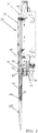
- FIGS. 1 and 2 illustrate an example of a pipette device assembly 10 comprising an example of a pipette device 20, an example embodiment of an expanding mandrel collet coupling device 100 or pipette tip coupler, and an example embodiment of a disposable pipette tip 220 removably coupled to the pipette device 20 by way of the expanding mandrel collet coupling device 100.
- the pipette device 20 comprises a body 22 supporting an aspirating and dispensing device 24 comprising a plunger 26 operatively coupled to and driven by a motor 28.
- the plunger 26 resides within a plunger cylinder 30 extending from a distal or lower end 32 of the body 22 of the pipette device 20.
- Pipette device 20 further comprises an aspirating and dispensing cylinder 34 that is at least partially disposed within plunger cylinder 30 at a location axially aligned with and distally below the plunger 26.
- the aspirating and dispensing cylinder 34 distally transitions into a distal mounting flange 36 for attaching with the expanding mandrel collet coupling device 100 which, in turn, removably couples with the disposable pipette tip 220.
- the pipette device 20 further comprises a hollow piston or squeeze sleeve 46 having a proximal or upper end 48 and a distal or lower end 50.
- the squeeze sleeve 46 circumscribes both the plunger cylinder 30 and the aspirating and dispensing cylinder 34 and is operatively coupled to a squeeze motor 52.
- the squeeze motor 52 of pipette device assembly 10 is supported on the body 22 of the device 20 and is operatively coupled to and drives a lead screw 54 which, in turn, couples to an axially translating lead nut 56 that is operatively coupled to a squeeze linkage 58.
- the squeeze linkage 58 is operatively coupled to the proximal or upper end 48 of the squeeze sleeve 46 via squeeze linkage arm 60 such that rotation of the squeeze motor 52 in a first direction results in linear axial translation of the squeeze sleeve 46 in a distal or vertically downward direction along longitudinal channel axis 80 ( FIG.
- the pipette device 20 further comprises an ejection sleeve 62 used to eject the disposable pipette tip 220 from the pipette device 20 wherein the ejection sleeve 62 is axially movable relative to the aspirating and dispensing cylinder 34 ( FIG. 2 ) and comprises a proximal or upper end 64, a distal or lower end 66, and an ejection sleeve arm 68 attached at a first end to the ejection sleeve 62 adjacent upper end 64 and having an opposing second end attached to a fist end of a plunger device 70.
- the ejection sleeve 62 is axially movable relative to the aspirating and dispensing cylinder 34 ( FIG. 2 ) and comprises a proximal or upper end 64, a distal or lower end 66, and an ejection sleeve arm 68 attached at a first end to the ejection sleeve
- the plunger device 70 comprises an opposing end surface 72 abutting one end of an ejection sleeve spring 74 having an opposing spring end abutting against an upper surface portion 76 of the body 22 of device 20 wherein the ejection sleeve spring 74 is captured between the surfaces 72, 76 to be spring loaded to bias the plunger device 70 and attached sleeve 62 in a normally pipette tip ej ected state.
- the normally pipette tip ejected state is configured to require a force, such as coupling to pipette tip 220, to overcome the ejection sleeve spring force in order to axially push the ejection sleeve 62 to a retracted state as illustrated in FIG. 2.
- FIG. 2 further illustrates that the spring 74 circumscribes a central spring guide member 78 for retaining the shape of the spring 74 and for preclude the spring 74 from buckling.
- the spring 74 is dimensioned in such a way that the force exerted on the pipette tip 220 by sleeve 62 in the course of its relaxation is sufficient to assist in ejecting the tip 220 from the expanding mandrel collet coupling device 100.
- the expanding mandrel collet coupling device 100 and the disposable pipette tip 220 can be practiced on other embodiments of pipette devices wherein the example of pipette device 20 is provided by way of example only and not limitation.
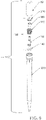
- the expanding mandrel collet coupling device 100 comprises an elongated central body member 102; a distal or lower elastomeric element 140 carried at a distal or lower end portion of the elongated central body member 102; an expanding collet 170 configured to circumscribe the elongated central body member 102 and comprising a segmented collar 200; and an annular wedge or washer 210.
- the annular wedge 210 is configured to receive an upper portion of the elongated central body member 102 therethrough for axially movably surmounting an interior of the expanding collet 170 adjacent segmented collar 200 for radially outwardly expanding the segmented collar 200 from the unexpanded state having a first circumference to an expanded state having a second conference greater than the first circumference as a function of the axial location of the annular wedge 210 relative to the central body member 102 for engaging the interior of the pipette tip 220 as illustrated in FIG. 29 from a disengaged state as illustrated in FIG. 21 .
- the expanding mandrel collet coupling device 100 comprises the elongated central body member 102 extending between a proximal or upper annular end face 104 and a distal or lower annular end face 130 along a longitudinal central axis 90.
- the upper annular end face 104 of central body member 102 comprises an outer chamfered periphery 106 that transitions into an elongated tubular upper shank member 108 that distally transitions into an annular tapered portion 110.
- shank member 108 is threaded for assembly with distal mounting flange 36, which has corresponding threads.
- Annular tapered portion 110 decreases in diameter from shank member 108 and distally transitions into a cylindrical neck portion 112.
- the cylindrical neck portion 112 distally transitions into a cylindrical collar 114 that has a diameter greater than a diameter of the cylindrical neck portion 112.
- the cylindrical collar 114 is followed by a lower cylindrical body member 120 that has a diameter greater than a diameter of the cylindrical neck portion 112.
- Body member 120 distally extends from the cylindrical collar 114 to an upper annular shoulder end or stop surface 122 of a distal cylindrical stem portion surface 124 that has a diameter greater than a diameter of the lower cylindrical body member 120.
- the distal cylindrical stem portion surface 124 transitions from upper annular shoulder end 122 into a round end plate 126 having an upper surface 128 and a lower surface defined by the distal or lower annular end face 130.
- the end plate 126 has a diameter greater than a diameter of the stem portion surface 124 wherein the distal stem portion surface 124 defines a distal or lower groove portion 132 of the expanding mandrel collet coupling device 100.
- the elongated central body member 102 comprises an interior cylindrical channel surface 134 defining an open ended cylindrically shaped central channel or passageway 136 extending through the central body member 102 between the upper annular end face 104 and the lower annular end face 130 along the longitudinal central axis 90 for providing open channel communication through the elongated central body member 102 and to the open ended pipette channel 40 longitudinally extending along the longitudinal channel axis 80 of the pipette device assembly 10.
- the expanding mandrel collet coupling device 100 further comprises the distal or lower elastomeric element 140 coaxially carried at the distal end portion of the elongated central body member 102.
- the distal elastomeric element 140 comprises an annular body 142.
- Annular body 142 comprises an interior surface 144 defining a central opening 146, a top surface 148, a peripheral exterior surface 150, and a bottom surface 152.
- Central opening 146 is dimensioned to closely or tightly circumscribe the distal cylindrical stem portion 124 of the expanding mandrel collet coupling device 100 while shaped to reside within groove 132 and extend radially outwardly circumferentially beyond end plate 126 as illustrated in FIG. 7 .
- the distal elastomeric element 140 comprises a circumferentially continuous, generally circular cross section area 154 as is illustrated in FIG. 15 .
- the expanding mandrel collet coupling device 100 further comprises a spacer 160 configured to circumscribe or be integrally formed with the elongated central body member 102.
- spacer 160 comprises a cylindrical body 162 extending between a superior end 164 and an inferior end 165.
- the cylindrical body 162 comprises an interior circumscribing surface 166 ( FIG. 15 ) that defines an open ended passageway 168 extending through the body 162 wherein the passageway 168 is dimensioned to closely or tightly circumscribe the lower cylindrical body member 120 of the elongated central body member 102.
- the spacer 160 is further configured to be circumscribed by the expanding mandrel collet 170 wherein the superior end 164 of spacer 160 abuts against the distal end of the mounting flange 36 and the inferior end 165 abuts against an interior annular shoulder stop surface 177 of a annular base portion 172 of the expanding mandrel collet 170 wherein the annular base portion 172 further comprise a distal or lower annular end 176 that mounts on the distal annular shoulder stop surface 122 of the distal cylindrical stem portion 124 ( FIG. 8 ) of the elongated central body member 102 for securing the expanding mandrel collet 170 coaxially with the central body member 102 along the longitudinal central axis 90.
- the shank member 108 of the expanding mandrel collet coupling device 100 is configured to fit within the distal mounting flange 36 of the aspirating and dispensing cylinder 34 for operatively coupling the expanding mandrel collet coupling device 100 to the pipette device 20 and removably coupling the disposable pipette tip 220 to the pipette device 20 by way of the expanding mandrel collet coupling device 100 such that the longitudinal channel axis 80 and central axis 90 form a coincident or common longitudinal channel axis.
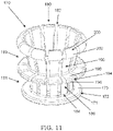
- the expanding mandrel collet 170 comprises a plurality of circumferentially spaced apart upwardly extending collet arms 180 transitioning upwardly from ends 184 attached to the lower annular base portion 172 to free segmented ends 200 defining the segmented collar disposed axially above the lower annular base portion 172.
- the plurality of circumferentially spaced apart upwardly extending collet arms 180 are separated from one another by one of a plurality of circumferentially spaced apart upwardly extending slots 182.
- each of the plurality of upwardly extending collet arms 180 comprises a respective lower arm portion 186 transitioning into a respective upper arm portion 190.
- the plurality of circumferentially spaced apart lower arm portions 186 form a generally cylindrically shaped circumscribing lower body portion 181 and the plurality of circumferentially spaced apart upper arm portions 190 form a frustoconically shaped circumscribing upper body portion 183 radially outwardly and upwardly transitioning from the lower body portion 181.
- the lower body portion 181 can be configured with a slight upward taper or increased circumference with respect the distal or lower annular base portion 172.
- the distal or lower annular base portion 172 comprises a distally or downwardly facing base surface 171 and a proximally or upwardly facing base surface 173.
- the distally facing base surface 171 downwardly transitions into an abbreviated distal or lower end annular stem surface 174 that terminates to a distal or lower annular base portion end 176 of the lower annular base portion 172.
- the base surface 171 and base portion 172 define an abbreviated distal end annular groove 178 as illustrated in FIG. 14 .
- the lower annular base portion 172 further comprises an inner cylindrical surface 175 upwardly transitioning into the interior annular shoulder stop surface 177 on which spacer 160 is mounted on as illustrated in FIG. 15 .
- the inner cylindrical surface 175 is dimensioned with an inner diameter that closely circumscribes lower cylindrical body member 120 of central body member 102 at a location directly above the annular shoulder stop surface 122 of central body member 102 wherein the annular shoulder stop surface 122 defines the axial stop for the lower annular base portion end 176 of the expanding mandrel collet 170 such that the expanding mandrel collet 170 is centrally mounted on and about the elongated central body member 102.
- the lower arm portions 186 comprise distal or lower end portions 184 circumferentially spaced apart and attached to the lower annular base portion 172. As illustrated in FIG. 12 , the lower arm portions 186 further comprise upper end portions defining medial arm portions having interior annular recessed segmented surfaces or grooves 191 and exterior radially outwardly extending annularly segmented stop disk portions 194.
- segmented stop disks 194 circumscribe and radially extend from an exterior of the medial arm portions of the plurality of circumferentially spaced apart upwardly extending collet arms 180 defining an annular segmented stop disk.
- each of the segmented stop disks 194 comprises a proximally or upwardly facing stop disk surface 198 and a distally or downwardly facing stop disk surfaces 196.
- the plurality of lower arm portions 186 comprise inner cylindrical or interior segmented surfaces 188 dimensioned with an inner diameter that closely circumscribes the spacer 160 which circumscribes the elongated central body member 102.
- the distal or lower end of the interior segmented surfaces 188 radially inwardly transition into the interior annular shoulder stop surface 177 that provide the stop surface for spacer 160 as detailed above.
- the proximal or upper end of the interior segmented surfaces 188 transition into the interior annular recessed segmented surface or groove 191.
- the upper arm portions 190 upwardly and radially outwardly transition from the segmented stop disks 194 to a plurality of radially outwardly projecting segments defining segmented collar 200 wherein the segmented collar 200 is configured to circumscribe longitudinal central axis 90 of the expanding mandrel collet coupling device 100 as illustrated in FIG. 7 .
- the plurality of circumferentially spaced apart radially outwardly and upwardly extending upper arm portions 190 including the segments respectively comprise interior surfaces 192 forming an inclined segmented interior surface complemental to the proximally inclined annular side surface 216 of the annular wedge 210 ( FIG. 7 ) wherein each comprises a distally decreasing circumference relative to the Z axis and wherein the interior surfaces 192 of the upper arm portions 190 form a radially outwardly and upwardly extending conically shaped gap 204 with respect to the elongated central body member 102 ( FIG. 15 ).
- the upwardly and radially outwardly inclined inner surfaces 192 of the plurality of circumferentially spaced apart upper arm portions 190 define a distally tapering cone gap 204 between the inner surfaces 192 of the upper arm portions 190 and the combination of the lower portion of the mounting flange 36 and the upper portion of spacer 160.
- the tapering cone gap 204 is configured to receive the lower portion of annular wedge 210 such that the annular wedge shaped or inclined exterior side surface 216 of the annular wedge 210 abuts the inner surfaces 192 of the plurality of free ends 199 supporting the projecting segments defining segmented collar 200.
- the annular wedge 210 comprises a resilient wedge shaped annular body having a circumferentially continuous, generally wedge shaped cross section 211.
- the annular wedge 210 comprises a central interior annular surface 212 defining a central annular opening 213 extending through the annular wedge 210 configured to moveably circumscribe body 102.
- annular wedge 210 comprises a top planar circular surface 214 configured to make an electrical contact switch with the LLD circuit ring end 366 of the LLD circuit 364 and radially outwardly extending from the central interior annular surface 212 to a circumscribing outer edge surface 215.
- annular wedge 210 comprises a radially outwardly proximally inclined side surface 216 radially upwardly and outwardly extending from a bottom annular end 218 to an underside of an annular peripheral lip 219 that radially extends outwardly and terminates to the circumscribing outer edge surface 215. Accordingly, radially outwardly proximally inclined side surface 216 defines a distally tapering wedge surface 216.
- the central annular opening 213 of the annular wedge 210 is dimensioned to allow passage of the distal mounting flange 36 and elongated tubular upper shank member 108 so as to allow a seating abutment of the radially outwardly proximally inclined side surface 216 of the annular wedge 210 with the inner surfaces 192 of the plurality of radially outwardly projecting segments 200 such that distal axial translation of annular wedge 210 results in the radial projection of the radially outwardly projecting segments 200 of the expanding mandrel collet 170 and subsequent proximal translation of annular wedge 210 results in the radial retraction of the radially outwardly projecting segments 200 of the expanding mandrel collet 170.
- the shank member 108 of the expanding mandrel collet coupling device 100 is configured to fit within the distal mounting flange 36 of the aspirating and dispensing cylinder 34 for operatively coupling the expanding mandrel collet coupling device 100 to the pipette device 20 of the pipette device assembly 10 such that the longitudinal channel axis 80 and longitudinal central axis 90 form a coincident or common axis.
- the expanding collet 170 is further configured to radially outwardly expand the segmented collar 200 from an unexpanded state having a first circumference as generally illustrated in FIG. 7 to an expanded state having a second circumference greater than the first circumference as generally illustrated in FIG. 14 when, under a force provided by the squeeze sleeve 46, the annular wedge 210 moves axially downwardly.
- the expanding mandrel collet coupling device 100 is configured to be fitted within the distal mounting flange 36 with the top planar circular surface 214 of the annular wedge 210 disposed adjacent the distal end 50 of the squeeze sleeve 46. Accordingly, and referring to FIGS.
- the actuation of the squeeze motor 52 in the first direction results in linear axial translation of the squeeze sleeve 46 in a distal or vertically downward direction for applying a force axially on top surface 214 of the annular wedge 210 resulting in the distally tapering wedge surface 216 axially sliding down further into the cone gap 204 for forcing the distally tapering wedge surface 216 against the interior surfaces 192 of the plurality of radially outwardly projecting segments 200 for pushing the exterior radially outwardly facing surfaces 202 ( FIG.
- the expanding mandrel collet coupling device 100 provides an open communication coupling between the disposable pipette tip 220 and the pipette device 20 of the pipette device assembly 10.
- the disposable pipette tip 220 comprises an elongated tubular pipette tip body 222 having a central longitudinal axis 224.
- Pipette tip body 222 comprises an elongated circumscribing sidewall 226 longitudinally extending along the central longitudinal axis 224 between a proximal or upper annular end face 228 and a distal or lower annular end face 230 defining circumscribing open proximal and distal annular ends 232 and 234 respectively.
- the elongated circumscribing sidewall 226 comprises an interior surface 236 defining a pipette tip passage opening 238 extending longitudinally along the central longitudinal axis 224 of the pipette tip body 222 between the open upper annular end 232 and the open lower annular end 234.
- the pipette tip passage opening 238 provides open communication from an area exterior to the open distal annular end 234 ( FIG. 18 ), through the pipette tip 220, and to the pipette device channel 40 ( FIG. 15 ) by way of the central channel 136 of the expanding mandrel collet coupling device 100 ( FIG. 16 ) when the coupling device 100 is coupled between the pipette device 20 and the pipette tip 220.
- the central longitudinal axis 224 of the pipette tip body 222 is coextensive with the longitudinal channel axis 80 of the pipette device 20.
- the interior surface 236 of the elongated circumscribing sidewall 226 comprises an uppermost annular chamfered interior surface 240 that distally extends radially inward from the proximal annular end face 228 of the pipette tip 220 and terminates by transitioning into a first substantially cylindrical interior surface section 242 having a first diameter.
- the first substantially cylindrical interior surface section 242 comprises an axially arcuate circumferential interior surface 244 formed into the elongated circumscribing sidewall 226 defining a circumferential annular groove 246.
- Annular groove 246 divides the first substantially cylindrical interior surface section 242 into an upper first substantially cylindrical interior surface portion and a lower first substantially cylindrical interior surface portion of substantially equal diameter. Accordingly, the annular groove 246 provides a circumferential radially outwardly extending concave shaped interior surface interruption of the first substantially cylindrical interior surface section 242 with an arcuate surface longitudinal cross section.
- the arcuate circumferential interior surface 244 is also configured in alternative surface cross sections as discussed below.
- the first substantially cylindrical interior surface section 242 is devoid of arcuate circumferential interior surface 244 defining the circumferential annular groove 246.
- the axially arcuate circumferential interior surface 244 defining the annular groove 246 comprises an upper annular transition edge 248 distally transitioning into an upper axially arcuate circumferential surface sector portion 250 of the axially arcuate circumferential interior surface 244.
- the upper axially arcuate circumferential surface sector portion 250 distally transitions into a lower axially arcuate circumferential surface sector portion 252 of the axially arcuate circumferential surface 244.
- lower axially arcuate circumferential surface sector portion 252 terminates to a lower annular transition edge 254.
- the upper axially arcuate circumferential surface sector portion or upper portion 250 provides the annular groove 246 with an increasing radius relative to the central longitudinal axis 224 ( FIG. 17 ) of the pipette tip 220 from the upper annular transition edge 248 to a maximum radius of the annular groove 246 relative to the central longitudinal axis 224 that defines a circumferential annular center of the annular groove 246.
- the lower axially arcuate circumferential surface sector portion or lower portion 252 provides the annular groove 246 with a decreasing radius relative to the central longitudinal axis 224 of the pipette tip 220 from the maximum radius defining the circumferential annular center of the of the annular groove 246 to the lower annular transition edge 254.
- the first substantially cylindrical interior surface section 242 is axially distally proceeded by a second substantially cylindrical interior surface section 262 having a second diameter less than the first diameter of the first substantially cylindrical interior surface section 242 for forming a proximally facing, radially inwardly extending annular shoulder seat surface or axial stop surface 260 interposed between the first and second substantially cylindrical interior surface sections 242, 262.
- the proximally facing axial stop surface 260 is substantially planar and generally perpendicular to the central longitudinal axis 224 of the pipette tip body 222 as illustrated in FIG. 17 .
- the second substantially cylindrical interior surface section 262 is axially distally proceeded by a third substantially cylindrical interior surface section 272 having a third diameter less than the second diameter of section 262.
- a frustoconical annular sealing seat or stop surface 270 Interposed between the second section 262 and the third section 272 is a frustoconical annular sealing seat or stop surface 270 defining a circumferential radially inwardly angled and distally extending distal working surface 270.
- the frustoconical annular sealing seat surface 270 comprises an upper annular sealing seat edge 266 defining an annular border between the second substantially cylindrical interior surface section 262 and the frustoconical annular sealing seat surface 270.
- the frustoconical annular sealing seat surface 270 comprises a lower annular sealing seat edge 268 defining an annular border between the frustoconical annular sealing seat surface 270 and the third interior surface section 272 wherein a diameter of the upper annular sealing seat edge 266 is greater than a diameter of the lower annular sealing seat edge 268.
- the frustoconical annular sealing seat surface 270 defines the circumferential radially inwardly angled and distally extending second working surface or sealing seat surface 270 interposed between the second substantially cylindrical interior surface section 262 and the third substantially cylindrical interior surface section 272.
- the sealing seat surface 270 is disposed at an acute angle relative to the central longitudinal axis 224 wherein the acute angle defines an acute sealing seat surface angle relative to the central longitudinal axis 224 ( FIG. 17 ).
- the preferred acute sealing seat surface angle relative to the central longitudinal axis 224 is about 15 degrees to about 35 degrees with a preferred angle of about twenty-five degrees.
- the acute sealing seat surface angle of an alternative sealing seat surface 2270 relative to the central longitudinal axis 224 is about 90 degrees.
- FIG. 18 further illustrates that in succession to the third substantially cylindrical interior surface section 272 is a fourth interior surface section 274 that is distally followed by a fifth interior surface section 275.
- the fourth interior surface section 274 distally tapers or decreases in diameter from a distal annular end 276 of the third substantially cylindrical interior surface section 272 to a proximal annular end 278 of the fifth interior surface section 275.
- the fifth interior surface section 275 distally tapers or decreases in diameter from the proximal annular end 278 of the fifth interior surface section 275 to the open distal annular end 234 of the pipette tip 220 that is intended for immersion.
- the fifth interior surface section 275 has a greater taper than the fourth interior surface section 274.
- one example embodiment of the pipette tip 220 comprises a plurality of circumferential spaced apart longitudinally extending external ribs 280 disposed on the tubular pipette tip body 222 adjacent the periphery of the proximal annular end face 228 and longitudinally extending externally therefrom to an exterior area of the circumscribing sidewall 226 that is adjacent to the third substantially cylindrical interior surface section 272 as illustrated in FIG. 18 .
- the plurality of circumferential spaced apart longitudinally extending external ribs 280 may be utilized to provide support for the pipette tip 220 on or in a support surface 282 through which the pipette body 222 has passed via, for example, a support surface aperture opening 284.
- a support surface aperture opening 284 One example embodiment of the support surface 282 can be in the form of, but not limited to, lab ware in the form of a tip rack as is known in the art, and informed by the present disclosure.
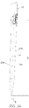
- one or more of the pipette device assemblies 10 is employed in an automated pipetting workstation or system 300 that generally provides, but is not limited to, programmed transfers of liquid between containers which comprises mounting and ejection processes of one or more disposable pipette tips 220 to the expanding mandrel collet coupling device 100 operatively carried by the pipette device 20 for carrying out, for example, the programmed transfers of liquid between containers.
- the automated pipetting workstation 300 generally comprises a robotic gantry 302 that carries at least one pipette device assembly 10 vertically above a horizontally disposed workstation deck 304.
- the pipette device assembly 10 can comprise a single channel pipetting head or a multi-channel pipetting head.
- the robotic gantry 302 typically provides two or three degrees of freedom wherein three degrees of freedom comprises longitudinal translation along an axis defining an X-axis, latitudinal translation along an axis defining a Y-axis, and vertical (up and down) translation along an axis defining a Z-axis so that the pipette device assembly 10 can move along the length (X-axis) and width (Y-axis) of the deck and vertically up and down (Z-axis) relative thereto.
- the robotic gantry is typically provided with the ability to translate the pipette device assembly 10 vertically and either longitudinally or laterally.
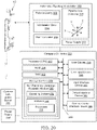
- the automated pipetting workstation 300 further comprises a main controller 306, a pipette axis controller 308, and a power supply 310 that provides power for the main controller 306, the pipette axis controller 308, and the pipette device assembly 10.
- a computer/controller 320 can also be employed with the workstation 300 and communicate with the main controller 306 and the pipette axis controller 308 for controlling the robotic gantry 302 and pipette device assembly 10 including the associated process protocols of the pipette device assembly 10 such as the disposable pipette tip 220 attaching and ejection (coupling and decoupling) processes detailed below.
- the computer/controller 320 typically comprises a processor device or central processing unit (CPU) 322, a hardware read only memory device (ROM) 324, a hardware main memory device (RAM) 326, a hardware storage memory 328 comprising a non-transitory computer readable medium or memory 330 having an operating system 332 and software 334 such as user defined processes 336 for the pipette device assembly 10 stored thereby, a user display 338, a user input device 340, an input interface 342, an output interface 344, a communication interface device 346, and a system bus 348 which comprises one or more conductor or communication paths that permit communication among the devices of the computer/controller 320.
- Computer/controller 320 may also be operatively couple to LAN and/or server 350.
- a power supply 352 provides power for the computer/controller 320.
- Examples of the above delineated automated pipetting workstation 300 including software are presently manufactured and sold by Hamilton Company, the assignee of the present patent application, located at 4970 Energy Way, Reno, Nevada 89502, United States of America.
- FIGS. 21 through 31 illustrate details of an example embodiment of successive stages of a pipette tip pickup process and, in particular, a method of securing attachment of the pipette tip 220 to the expanding mandrel collet coupling device 100 operatively carried by the pipette device 20.
- the pipette tip 220 may be supported by a support surface 282.
- the expanding mandrel collet coupling device 100 is connected to the pipette device 20, and upon command, the coupling device 100 is positioned over the open proximal end 232 of the pipette tip 220 wherein each of their respective central longitudinal axis is aligned along the Z-axis.
- the eject sleeve 62 is in the eject position
- the squeeze sleeve 46 is in the unsqueezed position
- the expanding mandrel collet 170 is in the relaxed state
- the distal O-ring 140 is in the unsqueezed state.
- FIG. 22 illustrates the expanding mandrel collet coupling device 100 being moved down along the Z-axis into the pipette tip 220 for lowering the distal, elastomeric carrying portion of the coupling device 100 to pass into the interior cylindrical proximal end portions of the pipette tip 220 to bring the distal O-ring 140 into contact with the annular sealing seat or stop surface 270 of the tip 220 while maintaining the distal O-ring 140 in the unsqueezed state and before the upwardly facing annular shoulder seat or stop surface 260 of the pipette tip 220 and the downwardly facing axial stop disk surface 196 of the stop disk 194 are mated.
- FIG. 23 illustrates the coupling device 100 being further moved down along the Z-axis.
- the squeeze sleeve 46 is moved down along the Z-axis and pushes against the LLD circuit ring end 366 which contacts with and pushes against the top surface 214 of the annular wedge 210 that surmounts the expanding mandrel collet 170 while maintaining the plurality of radially outwardly projecting segments 200 in the unexpanded state as detailed in FIG. 24 , maintaining the distal O-ring 140 in the uncompressed state as detailed in FIG.
- FIG. 26 illustrates the squeeze sleeve 46 being moved further down along the Z-axis for pushing the annular wedge 210 against the interior surface 192 of the plurality of radially outwardly projecting segments 200 for pushing them radially outwardly out and abutting the exterior radially outwardly facing rounded surfaces 202 of the plurality of radially outwardly projecting segments 200 against the upper axially arcuate circumferential surface sector portion 250 of the groove 246 of the disposable pipette tip 220 as detailed in FIG.
- the action of the plurality of radially outwardly projecting segments 200 extending or being projected into the groove 246 as detailed in FIG. 27 causes an axial upward force that starts the process of pulling the pipette tip 220 up for starting a process of seating the annular shoulder seat surface 260 of the pipette tip 220 with the axial stop shoulder surface 196 of the stop disk 194 for closing the gap 298 ( FIG. 23 ) and compressing the distal O-ring 140 with the sealing seat or stop surface 270 of the tip 220 as detailed in FIG. 28 .
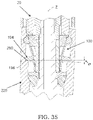
- FIG. 29 illustrates the squeeze sleeve 46 being moved down along the Z-axis a configured predetermined length until it is locked in position resulting in the annular wedge 210 being stopped and locked in position by the squeeze sleeve 46.
- the plurality of radially outwardly projecting segments 200 are radially extended to a desired distance or value as exemplified in FIG. 30 for fully seating the axial stop shoulder surface 196 of the expanding mandrel collet coupling device 100 against the annular shoulder seat surface 260 of the pipette tip 220 with the seating of the two surfaces 196, 260 being along an X-axis substantially perpendicular to the Z-axis for forming a normal datum between the two axes.
- the distal O-ring 140 is compressed to a desired distance or value as exemplified in FIG. 31 for seating the distal O-ring 140 with the annular sealing seat surface 270 of the tip 220 such that its cross-section is in its final compressed non-circular form thereby completing the coupling of securing the attachment of the pipette tip 220 with the expanding mandrel collet coupling device 100 operatively carried by the pipette device 20.
- the plurality of radially outwardly projecting segments 200 and the distal elastomeric element 140 work in combination to produce a segment and seal coupling that provides a fluid-tight seal wherein the plurality of radially outwardly projecting segments 200 are at least partially received within the circumferential groove 246 and at least partially seated on the circumferential arcuate interior surface 244 ( FIG. 18 ) defining the circumferential groove 246 and wherein the distal elastomeric element 140 seals against the surface 270 of the pipette tip 220 wherein in one embodiment surface 270 provides a radially inwardly angled and distally or downwardly extending surface.
- the plurality of radially outwardly projecting segments 200 move radially outward to engage the circumferential groove 246 ( FIG. 18 ) to couple with the tip 220 and move radially inward for releasing the tip 220 as a function of movement of the annular wedge 210.
- Applying a force for moving the annular wedge 210 axially downwards results in the plurality of radially outwardly projecting segments 200 being urged to a radially outward position and releasing the force on the annular wedge 210 results in a release of energy from the cantilevered arms 180 ( FIG. 11 ) supporting the plurality of radially outwardly projecting segments 200 such that the segments spring back from the radially outward position to the radially inward position.
- FIGS. 21 through 31 illustrate, in reverse, details of successive stages of an example method or process of ejecting the pipette tip 220 from the expanding mandrel collet coupling device 100 operatively carried by the pipette device 20.
- This tip ejection process sequence is similar to the attachment or tip pickup securing process sequence except in reverse and
- FIG. 34 illustrates a distal O-ring axial force component of the compressed distal O-ring 140 that provides a force to help remove the tip 220 during the ejection process.
- the ejection process comprises the steps of: (1) positioning the tip where it is to be discarded, such as a waste container; (2) moving the squeeze sleeve 46 upward wherein force is released from the annular wedge 210 and, as a result, this force is also released from the plurality of radially outwardly projecting segments 200 so as to allow retraction from the groove 246 in the tip 220, the distal O-ring 140 starts to release stored elastic potential energy or spring energy as a force against the tip 220, and wherein the spring loaded eject sleeve 62 also pushes against the tip 220 to push it off such that the tip begins to release from the plurality of radially outwardly projecting segments 200; (3) continuing the movement of the squeeze sleeve 46 upward wherein the plurality of radially outwardly projecting segments 200 continue to retract from the groove 246 in the tip 220 and wherein the distal O-ring 140 and the spring loaded eject sleeve 62 pushes against the tip 2
- FIG. 32 illustrates a diagrammatical vector diagram of a plurality of radially outwardly projecting segments 200 of the expanding mandrel collet coupling device 100 initially extending into the groove 246 with radially rounded surface 202 of the plurality of radially outwardly projecting segments 200 contacting the upper corner of the tip groove above the center of the segment radius resulting in an axial upward force pulling the pipette tip 220 upward.
- the segment force (Fsegment_resultant) for each of the plurality of radially outwardly projecting segments 200 is comprised of two components: an axial force (Fsegment_axial) component and a radial force (Fsegment_radial) component.
- Fsegment_axial increases as the distance between the center of the segment radius and corner of the groove increases. Accordingly, at the beginning of the tip pickup process, the segment axial force (Fsegment axial) starts out low as illustrated in FIG. 32 and, in detail in FIG. 33 , and increases to its maximum at the end of the tip pickup process as illustrated in FIG. 34 .
- the ratio of Z/R equals SIN (co) and SIN (co) is equal to (Fsegment_axial)/(Fsegment_resultant).
- (Fsegment axial) is equal to (Fsegment resultant) multiplied by the ratio of Z/R. From this, the result is that (Fsegment axial) increases as Z increases.
- the segment axial force (Fsegment axial) seats the stop disc 194 against the seat 260 of the tip 220 and provides the force required to overcome an O-ring axial force (Fdistal_ring_axial) and compress the distal O-ring 140.
- the O-ring 140 has an O-ring force (Fdistalring resultant) that results from being compressed and this O-ring force comprises two components: an axial component (Fdistal_ring_axial) and a radial component (Fdistal ring radial).
- the segment radial force (Fsegment radial) provides the radial force needed to lock the segment into the tip groove 246 ( FIG.
- the distal O-ring radial force component (Fdistal_ring_radial) provides the radial force needed to maintain the seal against the tip.
- segment to tip groove geometry that causes Fsegment_axial to increase as the segment enters the groove (increasing dimension Z) helps to overcome the O-ring axial force (Fdistal_ring_axial) so that the distal O-ring 140 can be completely compressed to the desired extent.
- the distal O-ring axial force component (Fdistal_ring_axial) provides force to help remove the tip 220 during the ejection process.
- the axial shoulder surface 196 of coupler 100 and the axial shoulder seat 260 of tip 220 are important for correct tip alignment. Accordingly, the coupler 100 and tip 220 are configured so that plurality of radially outwardly projecting segments 200 push the axial shoulder surface 196 and the axial shoulder seat 260 together to preclude misalignment because if the shoulders are not properly mated, especially if they are tilted, the misalignment error (E) may be significant.
- the positional error (E) is 3.14 millimeters. This is considered to be very high considering typical positional error tolerances are typically plus or minus 0.5 millimeters.
- FIG. 37 illustrates correct tip alignment with the axial shoulder surface 196 and the axial shoulder seat 260 in flush contact with one another to provide proper alignment and to maintain the tip axial distance D from the tip seat 260 to the distal end 230 constant to establish a known and controlled distance of the pipette tip end 230 along the vertical or axial axis Z and a perpendicular axis X.
- This is important to allow the pipette device to target small holes and small volumes of liquid. Additionally, smaller volumes of liquid can be transferred resulting from the known fixed distance of the pipette tip allowing for a controlled touch of the pipette tip/liquid to the working surface 290 onto or from which liquid 292 is to be transferred.
- the tip groove diameter A must be large enough to allow the segments 200 to pull the tip 220 up and adequately lock the tip 220 in place. Conversely, if it is too big, the segments 200 may not be able to be pushed in sufficiently to get a good lock. Additionally, internal diameters B and C must be larger than external diameter K of stop disc 194 and external diameter L of annular base 172, respectively. However, they must not be too much bigger, as this may result in a poor fit and/or misalignment.
- the tip seat to groove dimension S must be matched to the stop disk seat surface 196 to segment 200 center dimension M. This relationship is critical to the coupling between the tip 220 and stop disc 194.
- the dimension of the tip seat surface 260 to the O-ring seal land 266 in FIG. 19 must match the stop disk surface 196 to the distally facing perpendicular lip surface 171, dimension N in FIG. 39 .
- These dimensions control the amount that the distal O-ring 140 is compressed, and thus how well it seals.
- the tip surface 260 and stop disc seating/coupling surface 196 must be fully mated in order to provide proper alignment and maintain the tip axial distance D.
- the dimension D between the tip seat 260 to the distal end 230 (or axial distance) along with the mating of the coupling seats establish a known and controlled distance of the pipette tip end. This is important to allow the pipette device to target small holes and small volumes of liquid. Additionally, smaller volumes of liquid can be transferred resulting from the known fixed distance of the pipette tip allowing for a controlled touch of the pipette tip/liquid to the working surface onto or from which liquid is to be transferred.
- the tip internal diameter G must be smaller than diameter L of base 172 in order to create a seat or land for the distal O-ring 140 to seal against. If diameter G is too large, then the distal O-ring may not seal well. If the diameter is too small, then the distal O-ring 140 may not fully compress and may prevent the stop disc 194 from seating, or may cause harm to the distal O-ring 140. Additionally, the ramp length H along with the diameter G control the seat or land that mates with the O-ring 140. These dimensions are critical in providing a good O-ring seal. If ramp length H is too long, then the O-ring may not seal well. If H is too short, then the O-ring may not fully compress and may prevent the stop disc 194 from seating, or may cause harm to the O-ring 140.
- the pipette device assembly 10 further comprises a liquid level detection circuit assembly.
- the liquid level detection circuit assembly comprises a liquid level detection or LLD circuit board 360 comprising processing circuitry 362 electrically coupled to a LLD circuit contact 364 operatively coupled to the squeeze sleeve 46 that is made from an electrically non-conducting material so it is insulated from the rest of the assembly and wherein the contact 364 terminates to a circuit contact ring end 366 recessed in the bottom area of the squeeze sleeve 46 that is configured for selectively contacting the circuit contact ring end 366 with annular wedge 210 between the non-contact state illustrated in FIG. 22 and the contact state illustrated in FIG. 29 and therefore in contact with the plurality of conductive segments or elements coupling with the interior first working surface of a conductive tip 220.
- the LLD circuit contact 364 comprises the ring end 366 captured between the squeeze sleeve 46 and the annular wedge 210 wherein electrical closure or contact is made between the processing circuitry 362 of the LLD circuit board 360 ( FIG. 40 ) and the annular wedge 210 which is made from electrically conductive material.
- the annular wedge 210 pushes and makes electrical contact with the plurality of radially outwardly projecting segments 200 which are made using an electrically conductive nonpliable material.
- the plurality of radially outwardly projecting segments 200 make electrical contact with the tip 220 which is also made from an electrically conductive material.
- this completes the circuit between the processing circuitry 362 of the LLD circuit board 360 and the tip 220.
- stop disk mounting post or distal mounting flange 36 is formed from a non-conducting material. Therefore, the body member 102 and the plurality of radially outwardly projecting segments 200 are insulated from the rest of the assembly.
- the processing circuitry 362 of the LLD circuit board 360 detects a signal change when the tip 220 contacts liquid thereby having an ability to detect a surface of a liquid being transferred or a surface onto or from which liquid is being transferred. Again, actuation occurs when the coupling device 100 is attached to the tip 220 and the plurality of radially outwardly projecting segments 200 are radially pushed circumferentially and locked into the tip groove of the tip 220.
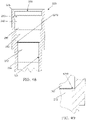
- FIG. 41 illustrates the example embodiment of the expanding mandrel collet coupling device 100 positioned over the example embodiment of the disposable pipette tip 220 comprising an alternative sealing seat surface 2270 having an angle of substantially ninety degrees relative to the central longitudinal Z axis of the pipette tip 220.
- FIG. 42 illustrates the example embodiment of the expanding mandrel collet coupling device 100 positioned in the disposable pipette tip comprising the alternative sealing seat surface 2270 wherein the tip 220 is lifted up to its final seated state and the annular wedge 210 moved into its final position for defining the final coupling state with the distal elastomeric element 140 in the final compressed and seated sealing state against the alternative sealing seat surface 2270.
- FIG. 43 details the final compressed state of the distal elastomeric element 140 against the alternative sealing seat surface 2270.
- FIG. 44 illustrates the upper interior of the disposable pipette tip 220 comprising another alternative sealing seat surface in the form of a circumferential radially concave sealing seat surface 3270.
- FIG. 45 details the circumferential radially concave sealing seat surface 3270 illustrated in FIG. 44 .
- FIG. 46 illustrates the example embodiment of the disposable pipette tip 220 illustrating detail of a further alternative sealing seat surface in the form of a circumferential radially convex sealing seat surface 4270.
- FIG. 47 details the circumferential radially convex sealing seat surface 4270 illustrated in FIG. 46 .
- FIG. 48 illustrates the example embodiment of the disposable pipette tip 220 illustrating a yet further alternative sealing seat surface in the form of a circumferential upward facing tooth edge sealing seat surface 5270.
- FIG. 49 details the circumferential upward facing tooth edge sealing seat surface illustrated in FIG. 48 .
- FIG. 50 is a fragmentary, longitudinal sectional, side elevational view of the example of the expanding mandrel collet coupling device 100 positioned over the example of the disposable pipette tip 220 comprising an alternative V-shaped groove 2246 defined by an V-shaped circumferential interior surface 2244 of the disposable pipette tip 220 opening toward the longitudinal Z axis and having a V-shaped cross section as illustrated.
- FIG. 51 illustrates the expanding mandrel collet coupling device 100 being positioned in the disposable pipette tip 220 comprising the alternative V-shaped groove 2246 ( FIG. 50 ) wherein the tip 220 is lifted up to its final state with the rounded surfaces 202 of the plurality of expanding mandrel collet segments 200 being extended into the V-shaped groove 2246 and into abutment against the V-shaped circumferential interior surface with the distal elastomeric element 140 in the final compressed and seated sealing state against the sealing seat surface 270 of the tip.
- FIG. 52 illustrates the rounded surface 202 of one of the plurality of expanding mandrel collet segments 200 being extended into the V-shaped groove 2246 and abutting against the V-shaped circumferential interior surface 2244 defining the V-shaped groove 2246.
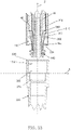
- FIG. 53 illustrates the example of the expanding mandrel collet coupling device positioned over a second example of a disposable pipette tip 1220 devoid of arcuate circumferential interior surface 244 defining the circumferential annular groove 246.
- FIG. 54 details the interior of the second example embodiment of the disposable pipette tip 1220 which is analogous in all portions with the exception that interrupted interior surface section 242 of the first substantially cylindrical interior surface section 242 illustrated in FIG. 18 is devoid of interruption thereby defining uninterrupted interior surface section 1242 of the disposable pipette tip 1220 wherein the interior surface section 1242 defines the first working surface.
- FIG. 55 illustrates the example embodiment of the expanding mandrel collet coupling device 100 positioned in the second example embodiment of the disposable pipette tip 1220 with the stop disk shoulder surface 196 of the coupling device 100 abutting against an axial stop surface 260 of the second example embodiment of the disposable pipette tip 1220 and the rounded surfaces 202 of the plurality of expanding mandrel collet segments 200 being extended against the interior surface 1242 of the circumscribing sidewall of the second example embodiment of the disposable pipette tip 1220 resulting in a deformation 1244 of the interior surface 1242 and with the distal elastomeric element 140 in the final compressed and seated sealing state against the sealing seat surface 270 of the second example embodiment of the disposable pipette tip 1220.
- FIG. 56 details the rounded surface 202 of one of the plurality of expanding mandrel collet segments 200 of the expanding mandrel collet coupling device 100 being extended against and deforming 1244 the interior surface 1242 of the circumscribing sidewall of the second example embodiment of the disposable pipette tip as is illustrated in FIG. 55 .
- FIGS. 57 through 67 are fragmentary, longitudinal sectional, side elevational views of the example of the disposable pipette tip comprising alternative groove shape embodiments relative to the circumferential annular tip groove for segments 200 illustrated in at least FIG. 19 and the V-shaped groove segments 200 illustrated in at least FIG. 50 .
- FIGS. 57 through 67 illustrate respective alternative groove configurations 2251 through 2261 for receipt of segments 200.
- FIG. 68 illustrates a second or alternative example embodiment of an expanding mandrel collet 2170 which is configured as a direct alternative to the expanding mandrel collet 170 ( FIG. 5 ) of the expanding mandrel collet coupling device 100 ( FIG. 5 ).
- the expanding mandrel collet 2170 is analogous in function to collet 170, but configured to improve performance and longevity.
- the expanding mandrel collet 2170 comprises a plurality of circumferentially spaced apart upwardly extending collet arms 2180 that radially outwardly extend and arcuately transition upwardly from the lower annular base portion 2172 and terminating to free segmented ends 2200 defining the segmented collar disposed axially above the lower annular base portion 2172.
- the plurality of circumferentially spaced apart upwardly extending collet arms 2180 are separated from one another by one of a plurality of circumferentially spaced apart upwardly extending kerfs or slots 2182.
- each of the plurality of upwardly extending collet arms 2180 comprises a respective lower arm portion 2186 transitioning into a respective upper arm portion 2190.
- the plurality of circumferentially spaced apart lower arm portions 2186 form a circumscribing lower body portion 2181 and the plurality of circumferentially spaced apart upper arm portions 2190 form a frustoconically shaped circumscribing upper body portion 2183 radially outwardly and upwardly transitioning from the lower body portion 2181.
- the distal or lower annular base portion 2172 comprises a distally or downwardly facing base surface 2171.
- the distally facing base surface 2171 downwardly transitions into an abbreviated distal or lower end annular stem surface 2174 that terminates to a distal or lower annular base portion end 2176 of the lower annular base portion 2172.
- the base surface 2171 and lower end annular stem surface 2174 define an abbreviated distal end annular groove.
- the lower annular base portion 2172 further comprises an inner cylindrical surface 2175 upwardly transitioning into the interior annular shoulder stop surface 2177.
- the lower arm portions 2186 comprise the circumferentially spaced apart lower end portions 2184 that are attached to the lower annular base portion 2172.
- the lower arm portions 2186 further comprise upper end portions defining medial arm portions having interior annular recessed segmented surfaces or grooves 2191 and exterior radially outwardly extending annularly segmented stop disk portions 2194.
- the segmented stop disks 2194 circumscribe and radially extend from an exterior of the medial arm portions of the plurality of circumferentially spaced apart upwardly extending collet arms 2180 defining an annular segmented stop disk.
- Each of the segmented stop disks 2194 comprises a proximally or upwardly facing stop disk surface 2198 and a distally or downwardly facing stop disk surfaces 2196. Additionally, the plurality of lower arm portions 2186 comprise inner cylindrical or interior segmented surfaces 2188 dimensioned with an inner diameter that closely circumscribes the spacer 160 ( FIG. 10 ) which circumscribes the elongated central body member 102 ( FIG. 10 ).
- the plurality of circumferentially spaced apart upper arm portions 2190 upwardly and radially outwardly transition from the respective lower arm portions 2186 and terminate into a plurality of free ends 2199 disposed above and radially outwardly from the lower arm portions 2186 wherein the plurality of free ends 2199 comprise radially outwardly projecting segments defining segmented collar 2200 wherein each segment comprises an exterior outwardly facing surface 2202 which, in one embodiment is outwardly rounded or arcuate in shape.
- the upper arm portions 2190 upwardly and radially outwardly transition from the segmented stop disks 2194 to a plurality of radially outwardly projecting segments defining segmented collar 2200.
- the plurality of circumferentially spaced apart radially outwardly and upwardly extending upper arm portions 2190 including the segments respectively comprise interior surfaces 2192 forming an inclined segmented interior surface complemental to the proximally inclined annular side surface 216 ( FIG. 13 ) of the annular wedge 210 ( FIG. 13 ).
- the expanding mandrel collet 2170 widens the base of each of the ends 2184 of each of the respective arms 2180 relative to the expanding mandrel collet 170 and radially extends the ends 2184 of arms 2180 outward in order to increase the radius of each of the arms 2180 relative to the expanding mandrel collet 170.
- Pushing the lower ends outward and increasing their diameter allows a larger chord segment or width at the bottom ends 2184 of each of extending arms 2180 wherein the increased width of each of extending arms 2180 improves the strength of each of extending arms 2180.
- increasing radial extension at the lower ends 2184 of arms 2180 provides increased strength. The coupling function is unchanged.
- the extending arms 2180 can be modelled as a cantilever beam in bending.
- Classical strength of materials techniques can be used to evaluate material stress when the beam is subject to bending, as occurs when the coupler is engaged and disengaged.
- the material stress can be analyzed with regard to fatigue strength to provide adequate product life.
- Increasing the width at the base of the beam, as well as increasing associated radii, are geometry modifications used to lower stress and improve strength.
- the pipette tip coupling device or expanding mandrel collet coupling device 100 provides improved life span.
- the radially outwardly projecting segments 200 of the expanding mandrel collet 170 provide a more rigid coupling for providing a stiffer joint between the pipette tip 220 and coupler 100.
- the coupler 100 will not be affected by ejecting a tip in free air.
- O-ring coupling life is adversely affected when the tip is ejected in free air because the O-ring is scuffed and abraded by the groove in the tip as the tip is pushed off by the spring loaded eject sleeve.
- the hardness of the radially outwardly projecting segments 200 resists the harmful acts of this scuffing and abrasion.
- the material of the expanding mandrel collet 170 can easily be made from conductive material in order to provide an electrical circuit to the tip for liquid level detection or other uses as detailed above.
- the radially outwardly projecting segments 200 of the expanding mandrel collet 170 are formed from hard and durable materials such as, but not limited to, metallic or hard plastic to provide improved life and because the discrete elements or segments are much harder than the plastic tip, they work into the tip groove more efficiently than soft elastomeric material such as an O-ring.
- the radially outwardly projecting segments 200 can be activated with a low squeeze/axial force because the mechanical design is efficient.
- a lower squeeze/axial force requirement improves the life on the associated parts providing the axial force.
- the radially outwardly projecting segments 200 allows the lower or distal seal 140 to have improved life span because the elastomeric material in not compressed as much.
- the coupler 100 allows the lower or distal seal 140 to be easily accessed if replacement is required. Also, the lower or distal seal 140 can be made from a greater variety of materials because it does not need to be conductive for the LLD circuit.
- maintenance costs are lower because of the improved life and easier accessibility to the lower or distal seal.
- tip alignment to the pipette device 20 is improved because of improved seating.
- an example not forming part of the claimed invention of a method for securing attachment of at least one pipette tip to at least one pipette tip coupler in the form of an expanding mandrel collet coupling device carried by a pipette device, the method comprising: (1) providing a pipette tip comprising a sidewall having an interior circumscribing surface defining a passage opening extending between an open distal end intended for immersion in a medium to be pipetted and an open proximal end opposite in an axial direction to the open distal end; (2) providing a pipette tip coupler comprising a distally facing axial stop shoulder surface formed by an axially stepped coupler shoulder of an exterior circumscribing surface of the pipette tip coupler, the distally facing axial stop shoulder surface complementary to a proximally facing axial stop surface formed by an axially stepped shoulder surface of the interior circumscribing surface of the side
- FIGS. 57 through 67 are fragmentary, longitudinal sectional, side elevational views detailing different alternative example embodiments to the circumferential annular tip groove 246 illustrated in at least in FIG. 19 and the V-shaped groove segments 200 illustrated in at least FIG. 50 .
- FIGS. 57 through 67 illustrate respective alternative groove configurations 2251 through 2261 for receipt of segments 200.
- the segments of the coupler may comprise radially outwardly faces complementary to the respective different alternative example embodiments of the respective groove configurations 2251 through 2261.
- the first working surface is in the form of, but not limited to, the respective groove configurations or the uninterrupted configuration illustrated in FIGS.
- the tip distal O-ring sealing seat 270 may have different geometries in the form of, but not limited to, flat conical, concave radius, convex radius, step, et cetera.
- the distal O-ring may have alternate shapes than an O-ring and may be in the form of, but not limited to, configurations complementary to the tip distal O-ring sealing seat 270.
Claims (16)
- Ensemble dispositif de couplage de pointe de pipette (100) et pointe de pipette (220) comprenant :une pointe de pipette (220) comprenant une paroi latérale entourante (226) avec un passage intérieur ouvert (238) incluant une surface intérieure (236) s'étendant le long d'un axe longitudinal central (224) de la pointe de pipette (220) entre une extrémité proximale ouverte (232) et une extrémité distale ouverte (234) de la pointe de pipette (220) ;un dispositif de couplage de pointe de pipette (100) comprenant :
un corps central (102) comprenant :un manche proximal (108) incluant une face d'extrémité proximale (104) ;une portion tige distale (124) ayant un premier diamètre ;une plaque d'extrémité (126) ayant un deuxième diamètre qui est plus grand que le premier diamètre, la plaque d'extrémité (126) étant distale par rapport à la portion tige distale (124) ; etune surface entourante intérieure à extrémité ouverte (134) formant un passage ouvert (136) s'étendant longitudinalement à partir de la face d'extrémité proximale (104) à travers la plaque d'extrémité (126) ;un élément élastomère (140) disposé autour de la portion tige distale (124) et adjacent à la plaque d'extrémité (126) ;une bague à expansion (170) disposée autour du corps central (102), la bague à expansion (170) comprenant :
une base annulaire (172) comprenant :une portion disque proximale (171, 173) ; etune portion extrémité de tige de bague distale (174, 176) ; caractérisé en ce que la base annulaire (172) comprend en outre :
une pluralité de bras flexibles s'étendant vers le haut espacés dans le plan circonférentiel (180), chaque bras de la pluralité de bras flexibles s'étendant vers le haut espacés dans le plan circonférentiel (180) comprenant :une extrémité distale attachée à la portion disque (171, 173) ;une portion bras libre proximale (190) ayant une surface interne ;une surface externe incluantun segment de disque d'arrêt s'étendant radialement vers l'extérieur (194) ; etdans lequel une pluralité des segments de disque d'arrêt (194) forme un disque d'arrêt segmenté ;dans lequel les portions bras libre proximales (190) de la pluralité de bras flexibles s'étendant vers le haut espacés dans le plan circonférentiel (180) sont aptes à présenter une expansion radiale relativement au corps central (102) entre un état non expansé avec une première circonférence et un état expansé avec une deuxième circonférence qui est plus grande que la première circonférence ; etdans lequel une portion supérieure de chacune des portions bras libre proximales (190) de la pluralité de bras flexibles s'étendant vers le haut espacés dans le plan circonférentiel (180) est en butée contre une première surface interne de la paroi latérale entourante (226) de la pointe de pipette (220) afin d'assujettir la pointe de pipette (220) au dispositif de couplage de pointe de pipette (100), etdans lequel l'élément élastomère (140) est en butée contre une deuxième surface interne de la paroi latérale entourante (226) de la pointe de pipette (220) afin de former un joint entre le dispositif de couplage de pointe de pipette (100) et la pointe de pipette (220). - Ensemble dispositif de couplage de pointe de pipette (100) et pointe de pipette (220) de la revendication 1 dans lequel la portion disque proximale (171, 173) a un troisième diamètre; et la portion extrémité de tige de bague distale (174, 176) a un quatrième diamètre qui est inférieur au troisième diamètre.
- Ensemble dispositif de couplage de pointe de pipette (100) et pointe de pipette (220) de la revendication 1 dans lequel l'élément élastomère (140) comprend un joint torique.
- Ensemble dispositif de couplage de pointe de pipette (100) et pointe de pipette (220) de la revendication 1 comprenant en outre un intercalaire (160), l'intercalaire (160) comprenant un corps cylindrique (162) entourant le corps central (102).
- Ensemble dispositif de couplage de pointe de pipette (100) et pointe de pipette (220) de la revendication 1 comprenant en outre une cale annulaire (210) entourant de manière mobile le corps central (102), la cale annulaire (210) comprenant :une surface de cale proximale (214) ayant une première circonférence de cale ;une surface de cale distale (218) ayant une deuxième circonférence de cale qui est inférieure à la première circonférence de cale ;une surface extérieure (216), la surface extérieure (216) raccordant la surface de cale proximale (214) avec la surface de cale distale (218) ; etdans lequel la surface extérieure (216) de la cale annulaire (210) est en butée contre la surface interne (192) de chacune des portions bras libre proximales (190) de la pluralité de bras espacés dans le plan circonférentiel (180).
- Ensemble dispositif de couplage de pointe de pipette (100) et pointe de pipette (220) de la revendication 5 dans lequel la bague à expansion (170) et la cale annulaire (210) sont réalisées en un matériau électriquement conducteur.
- Ensemble dispositif de couplage de pointe de pipette (100) et pointe de pipette (220) de la revendication 1, la pointe de pipette (220) comprenant en outre :
une première section (242) formée dans la surface intérieure (236) de la paroi latérale entourante (226) distale par rapport à l'extrémité proximale ouverte (232), la première section (242) comprenant :une première portion supérieure cylindrique ayant un premier diamètre ;une première portion inférieure cylindrique ayant le premier diamètre ; etune rainure annulaire (246) interposée entre la première portion supérieure cylindrique et la première portion inférieure cylindrique ; etla première section (242) ayant une première longueur ;une deuxième section (262) comprenant une surface cylindrique formée dans la surface intérieure (236) de la paroi latérale entourante (226) distale par rapport à la première section (242), la deuxième section (262) ayant un deuxième diamètre qui est plus petit que le premier diamètre, et la deuxième section (262) ayant une deuxième longueur ;une surface d'épaulement d'arrêt (260) formée dans la surface intérieure (236) de la paroi latérale entourante (226) au niveau d'une interface de la première section (242) et de la deuxième section (262) ;une troisième section (272) comprenant une surface cylindrique formée dans la surface intérieure (236) de la paroi latérale entourante (226) distale par rapport à la deuxième section (262), la troisième section (272) ayant un troisième diamètre qui est plus petit que le deuxième diamètre, et la troisième section (272) ayant une troisième longueur ;un siège d'étanchéité (266, 268, 270) formé dans la surface intérieure (236) de la paroi latérale entourante (226) et interposé entre la deuxième section (262) et la troisième section (272), le siège d'étanchéité (266, 268, 270) comprenant :un bord de surface de siège d'étanchéité annulaire supérieur (266) au niveau d'une interface avec la deuxième section (262) ;un bord de surface de siège d'étanchéité annulaire inférieur (268) au niveau d'une interface avec la troisième section (272) ;une surface de siège d'étanchéité (270) interposée entre le bord de surface de siège d'étanchéité annulaire supérieur (266) et le bord de surface de siège d'étanchéité annulaire inférieur (268) ; etdans lequel le bord de surface de siège d'étanchéité annulaire supérieur (266) est plus grand en diamètre que le bord de surface de siège d'étanchéité annulaire inférieur (268) ;au moins une section frustoconique (274, 275) formée dans la surface intérieure (236) de la paroi latérale entourante (226) et entre la troisième section (272) et l'extrémité distale ouverte (234). - Ensemble dispositif de couplage de pointe de pipette (100) et pointe de pipette (220) de la revendication 7 dans lequel la surface d'épaulement d'arrêt (260) est une surface plane, annulaire qui est perpendiculaire à l'axe longitudinal central (224) de la pointe de pipette (220) ; et la troisième longueur est plus grande que la première longueur.
- Ensemble dispositif de couplage de pointe de pipette (100) et pointe de pipette (220) de la revendication 7 dans lequel la surface de siège d'étanchéité (270) est une surface plane, annulaire qui est perpendiculaire à l'axe longitudinal central (224) de la pointe de pipette (220).
- Ensemble dispositif de couplage de pointe de pipette (100) et pointe de pipette (220) de la revendication 7 dans lequel la surface de siège d'étanchéité (270) est une surface annulaire frustoconique.
- Ensemble dispositif de couplage de pointe de pipette (100) et pointe de pipette (220) de la revendication 7 dans lequel la rainure annulaire (246) est concave.
- Ensemble dispositif de couplage de pointe de pipette (100) et pointe de pipette (220) de la revendication 7 comprenant en outre une surface intérieure chanfreinée annulaire (240) formée dans la surface intérieure (236) de la paroi latérale entourante (226) s'étendant radialement vers l'intérieur à partir de l'extrémité proximale ouverte (232) et se terminant au niveau d'une extrémité proximale de la première section (242).
- Ensemble dispositif de couplage de pointe de pipette (100) et pointe de pipette (220) de la revendication 7 dans lequel l'au moins une section frustoconique (274, 275) comprend en outre :une quatrième section (274) formée dans la surface intérieure (236) de la paroi latérale entourante (226) distale par rapport à la troisième section (272) ; etune cinquième section (275) formée dans la surface intérieure (236) de la paroi latérale entourante (226) distale par rapport à la quatrième section (274) et proximale par rapport à l'extrémité distale ouverte (234), dans lequel la cinquième section (275) a une conicité plus grande que la quatrième section (274).
- Ensemble dispositif de couplage de pointe de pipette (100) et pointe de pipette (220) de la revendication 7 dans lequel la paroi latérale entourante (226) est réalisée en un matériau électriquement conducteur.
- Ensemble dispositif de couplage de pointe de pipette (100) et pointe de pipette (220) de la revendication 7 dans lequel la surface de siège d'étanchéité (270) est une surface concave annulaire.
- Ensemble dispositif de couplage de pointe de pipette (100) et pointe de pipette (220) de la revendication 7 dans lequel la surface de siège d'étanchéité (270) est une surface convexe annulaire.
Applications Claiming Priority (4)
| Application Number | Priority Date | Filing Date | Title |
|---|---|---|---|
| US201662350291P | 2016-06-15 | 2016-06-15 | |
| US201662350302P | 2016-06-15 | 2016-06-15 | |
| PCT/US2016/061308 WO2017218032A1 (fr) | 2016-06-15 | 2016-11-10 | Dispositif de pipettage, coupleur de pointe de pipette, et pointe de pipette : dispositifs et procédés |
| EP16905679.3A EP3471878B1 (fr) | 2016-06-15 | 2016-11-10 | Pointe de pipette |
Related Parent Applications (2)
| Application Number | Title | Priority Date | Filing Date |
|---|---|---|---|
| EP16905679.3A Division EP3471878B1 (fr) | 2016-06-15 | 2016-11-10 | Pointe de pipette |
| EP16905679.3A Division-Into EP3471878B1 (fr) | 2016-06-15 | 2016-11-10 | Pointe de pipette |
Publications (2)
| Publication Number | Publication Date |
|---|---|
| EP3581275A1 EP3581275A1 (fr) | 2019-12-18 |
| EP3581275B1 true EP3581275B1 (fr) | 2022-08-10 |
Family
ID=60661058
Family Applications (14)
| Application Number | Title | Priority Date | Filing Date |
|---|---|---|---|
| EP23211360.5A Pending EP4302878A1 (fr) | 2016-06-15 | 2016-11-10 | Dispositif de pipetage, coupleur de pointe de pipette et pointe de pipette : dispositifs et procédés |
| EP19187501.2A Active EP3581275B1 (fr) | 2016-06-15 | 2016-11-10 | Assemblage de coupleur de pointe de pipette et pointe de pipette |
| EP19187498.1A Active EP3578261B1 (fr) | 2016-06-15 | 2016-11-10 | Coupleur de pointe de pipette |
| EP19187494.0A Active EP3578260B1 (fr) | 2016-06-15 | 2016-11-10 | Pointe de pipette |
| EP16905679.3A Active EP3471878B1 (fr) | 2016-06-15 | 2016-11-10 | Pointe de pipette |
| EP19187507.9A Active EP3578262B1 (fr) | 2016-06-15 | 2017-01-31 | Dispositif de pipetage, coupleur de pointe de pipette et point de pipette |
| EP19187524.4A Active EP3578265B1 (fr) | 2016-06-15 | 2017-01-31 | Dispositif de pipetage, coupleur de pointe de pipette et pointe de pipette |
| EP19187509.5A Active EP3586968B1 (fr) | 2016-06-15 | 2017-01-31 | Dispositif de pipetage, coupleur de pointe de pipette et pointe de pipette |
| EP17813715.4A Active EP3471883B1 (fr) | 2016-06-15 | 2017-01-31 | Dispositif de pipettage, coupleur de pointe de pipette et pointe de pipette |
| EP19187513.7A Pending EP3586969A3 (fr) | 2016-06-15 | 2017-01-31 | Dispositif de pipetage, coupleur de pipette et pointe de pipette : dispositifs et procédés |
| EP19187515.2A Active EP3578263B1 (fr) | 2016-06-15 | 2017-01-31 | Dispositif coupleur de pointe de pipette |
| EP19187504.6A Active EP3599022B1 (fr) | 2016-06-15 | 2017-01-31 | Pointe de pipette |
| EP19187518.6A Active EP3578264B1 (fr) | 2016-06-15 | 2017-03-30 | Dispositif de couplage de pointe de pipette |
| EP17813722.0A Active EP3471884B1 (fr) | 2016-06-15 | 2017-03-30 | Dispositif de pipettage, coupleur d'embout de pipette et embout de pipette |
Family Applications Before (1)
| Application Number | Title | Priority Date | Filing Date |
|---|---|---|---|
| EP23211360.5A Pending EP4302878A1 (fr) | 2016-06-15 | 2016-11-10 | Dispositif de pipetage, coupleur de pointe de pipette et pointe de pipette : dispositifs et procédés |
Family Applications After (12)
| Application Number | Title | Priority Date | Filing Date |
|---|---|---|---|
| EP19187498.1A Active EP3578261B1 (fr) | 2016-06-15 | 2016-11-10 | Coupleur de pointe de pipette |
| EP19187494.0A Active EP3578260B1 (fr) | 2016-06-15 | 2016-11-10 | Pointe de pipette |
| EP16905679.3A Active EP3471878B1 (fr) | 2016-06-15 | 2016-11-10 | Pointe de pipette |
| EP19187507.9A Active EP3578262B1 (fr) | 2016-06-15 | 2017-01-31 | Dispositif de pipetage, coupleur de pointe de pipette et point de pipette |
| EP19187524.4A Active EP3578265B1 (fr) | 2016-06-15 | 2017-01-31 | Dispositif de pipetage, coupleur de pointe de pipette et pointe de pipette |
| EP19187509.5A Active EP3586968B1 (fr) | 2016-06-15 | 2017-01-31 | Dispositif de pipetage, coupleur de pointe de pipette et pointe de pipette |
| EP17813715.4A Active EP3471883B1 (fr) | 2016-06-15 | 2017-01-31 | Dispositif de pipettage, coupleur de pointe de pipette et pointe de pipette |
| EP19187513.7A Pending EP3586969A3 (fr) | 2016-06-15 | 2017-01-31 | Dispositif de pipetage, coupleur de pipette et pointe de pipette : dispositifs et procédés |
| EP19187515.2A Active EP3578263B1 (fr) | 2016-06-15 | 2017-01-31 | Dispositif coupleur de pointe de pipette |
| EP19187504.6A Active EP3599022B1 (fr) | 2016-06-15 | 2017-01-31 | Pointe de pipette |
| EP19187518.6A Active EP3578264B1 (fr) | 2016-06-15 | 2017-03-30 | Dispositif de couplage de pointe de pipette |
| EP17813722.0A Active EP3471884B1 (fr) | 2016-06-15 | 2017-03-30 | Dispositif de pipettage, coupleur d'embout de pipette et embout de pipette |
Country Status (5)
| Country | Link |
|---|---|
| US (22) | US10525460B2 (fr) |
| EP (14) | EP4302878A1 (fr) |
| JP (15) | JP2019518220A (fr) |
| CN (13) | CN110385153B (fr) |
| WO (3) | WO2017218032A1 (fr) |
Families Citing this family (20)
| Publication number | Priority date | Publication date | Assignee | Title |
|---|---|---|---|---|
| US11559802B2 (en) * | 2011-07-20 | 2023-01-24 | Avidien Technologies, Inc. | Pipette tip adapter |
| US10429403B2 (en) * | 2014-06-17 | 2019-10-01 | Yamaha Hatsudoki Kabushiki Kaisha | Head device for mounting dispensing tip thereon, and movement device using same |
| CN110385153B (zh) * | 2016-06-15 | 2022-05-17 | 汉密尔顿公司 | 移液装置、移液管末梢联接器和移液管末梢:装置和方法 |
| DE102016111910A1 (de) * | 2016-06-29 | 2018-01-04 | Eppendorf Ag | Dosierkopf, Dosiervorrichtung umfassend einen Dosierkopf und Verfahren zum Dosieren mittels eines Dosierkopfes |
| JP6737554B2 (ja) * | 2016-09-27 | 2020-08-12 | 株式会社エー・アンド・デイ | ピペットチップ装着用アダプタ |
| US11280805B2 (en) * | 2018-06-05 | 2022-03-22 | Chemthief, Llc | Robot device for collection of solid, liquid and/or multiphase samples |
| CN111408418A (zh) * | 2019-01-07 | 2020-07-14 | 苏州赛尼特格尔实验室科技有限公司 | 一种电子移液器及其精度控制方法 |
| PL3680017T3 (pl) * | 2019-01-08 | 2022-02-07 | Eppendorf Ag | Pipeta do używania z końcówką |
| EP3917671B1 (fr) * | 2019-01-28 | 2024-02-21 | Formulatrix International Holding Ltd | Pointe de pipette à déplacement positif pour automatisation de commande motorisée ou système d'instrument |
| WO2020191496A1 (fr) * | 2019-03-28 | 2020-10-01 | Fredsense Technologies Corp. | Dispositif de fixation destiné à des ensembles de distribution de fluide |
| USD901035S1 (en) | 2019-07-18 | 2020-11-03 | CLAS Automation | Pipette with a flared end |
| CN110560193A (zh) * | 2019-09-27 | 2019-12-13 | 佛山科学技术学院 | 一种枪头存放盒 |
| WO2021101550A1 (fr) * | 2019-11-21 | 2021-05-27 | Hamilton Company | Dispositif de pipetage, élément d'accouplement de pointe de pipette, et pointe de pipette : dispositifs et procédés |
| US20210213440A1 (en) * | 2020-01-15 | 2021-07-15 | Perkinelmer Health Sciences, Inc. | Pipette tips and methods and systems including same |
| FI3932557T3 (fi) * | 2020-07-02 | 2023-12-28 | Eppendorf Se | Monikanavainen pipettipää |
| JP7377985B2 (ja) | 2020-07-31 | 2023-11-10 | ハミルトン カンパニー | ピペッティングデバイス、ピペットチップカップラー、およびピペットチップ:デバイスおよび方法 |
| JP2022058269A (ja) * | 2020-09-30 | 2022-04-11 | 富佳生技股▲ふん▼有限公司 | 液体転移装置 |
| CN113083391B (zh) * | 2021-04-07 | 2022-04-12 | 宁儿医院股份有限公司 | 一种新型移液枪头填装装置 |
| CN113908899B (zh) * | 2021-09-17 | 2023-05-02 | 圣湘生物科技股份有限公司 | 移液装置、核酸提取、检测装置及移液器更换方法 |
| DE102022120212A1 (de) | 2022-08-10 | 2024-02-15 | Hamilton Bonaduz Ag | Pipettierspitze mit sich gekrümmt verjüngendem Aufnahmeraum |
Family Cites Families (131)
| Publication number | Priority date | Publication date | Assignee | Title |
|---|---|---|---|---|
| DE2034325C3 (de) * | 1970-07-10 | 1974-03-07 | Georg 8000 Muenchen Seiler | Zug- und Schubsicherung für Steckmuffen- Verbindungen |
| US3732734A (en) | 1972-05-25 | 1973-05-15 | Centaur Chemical Co | Micropipette with disposable tips |
| DE7518809U (de) * | 1975-06-12 | 1978-09-14 | Eppendorf Geraetebau Netheler & Hinz Gmbh, 2000 Hamburg | Pipettenspitze |
| DE2549477C3 (de) * | 1975-11-05 | 1982-01-07 | Eppendorf Gerätebau Netheler + Hinz GmbH, 2000 Hamburg | Pipettiervorrichtung |
| US4023716A (en) | 1976-04-20 | 1977-05-17 | Justin Joel Shapiro | Micro-dispensing liquid pipet |
| US4187724A (en) | 1978-01-11 | 1980-02-12 | Indicon Inc. | Replaceable tip for a pipette |
| FI57542C (fi) | 1978-06-02 | 1980-09-10 | Suovaniemi Finnpipette | Volymreglerbar pipett |
| FI60138C (fi) | 1979-03-23 | 1981-12-10 | Suovaniemi Finnpipette | Pipett |
| FR2474340A1 (fr) * | 1980-01-11 | 1981-07-31 | Marteau D Autry Eric | Pipette a deplacement positif perfectionnee |
| US4437586A (en) * | 1982-03-29 | 1984-03-20 | Eastman Kodak Company | Mechanically actuated pipette dispenser |
| CH671526A5 (fr) | 1985-12-17 | 1989-09-15 | Hamilton Bonaduz Ag | |
| US4707337A (en) * | 1986-08-11 | 1987-11-17 | Multi-Technology, Inc. | Medical micro pipette tips for difficult to reach places and related methods |
| JPS6396457U (fr) * | 1986-12-13 | 1988-06-22 | ||
| US4748859A (en) * | 1987-03-06 | 1988-06-07 | Rainin Instrument Co., Inc. | Disposable pipette tip |
| US4863695A (en) | 1987-04-28 | 1989-09-05 | Hewlett-Packard Company | Pipette assembly |
| US5104625A (en) * | 1989-10-04 | 1992-04-14 | Drummond Scientific Company | Pipetter device |
| US5200151A (en) * | 1990-05-21 | 1993-04-06 | P B Diagnostic Systems, Inc. | Fluid dispensing system having a pipette assembly with preset tip locator |
| US5111703A (en) * | 1990-09-10 | 1992-05-12 | Eastman Kodak Company | Liquid aspirating pipette and dispensing system |
| US5121642A (en) | 1990-12-19 | 1992-06-16 | Eastman Kodak Company | Liquid sampling method and apparatus |
| US5525302A (en) | 1991-02-01 | 1996-06-11 | Astle; Thomas W. | Method and device for simultaneously transferring plural samples |
| US5192511A (en) * | 1991-05-31 | 1993-03-09 | Tri-Continent Scientific, Inc. | Pipette tip and piston |
| US5232669A (en) | 1991-11-08 | 1993-08-03 | Abbott Laboratories | Pipette tip with self-aligning and self-sealing features |
| JPH06134323A (ja) * | 1992-10-27 | 1994-05-17 | Daikin Ind Ltd | ピペッタ |
| JP3395250B2 (ja) * | 1993-05-10 | 2003-04-07 | ソニー株式会社 | ピペット装置 |
| DE4341229C2 (de) | 1993-12-03 | 1995-09-07 | Eppendorf Geraetebau Netheler | Pipettensystem |
| EP0733404A1 (fr) * | 1995-03-24 | 1996-09-25 | Becton, Dickinson and Company | Embout de pipette |
| US5707218A (en) * | 1995-04-19 | 1998-01-13 | Nimbus, Inc. | Implantable electric axial-flow blood pump with blood cooled bearing |
| US6117394A (en) | 1996-04-10 | 2000-09-12 | Smith; James C. | Membrane filtered pipette tip |
| JPH09308704A (ja) * | 1996-05-22 | 1997-12-02 | Senju Sprinkler Kk | スプリンクラーヘッド |
| US5948359A (en) | 1997-03-21 | 1999-09-07 | Biogenex Laboratories | Automated staining apparatus |
| US6499363B1 (en) | 1997-12-12 | 2002-12-31 | The Sailor Pen Co., Ltd. | Tip for pipette and pipette with the same |
| CN2319632Y (zh) * | 1998-02-26 | 1999-05-19 | 张春亮 | 自动调节密封性的密封装置 |
| US6495106B1 (en) | 1998-03-24 | 2002-12-17 | Biogenex Laboratories | Automated staining apparatus |
| CN1248495A (zh) * | 1998-09-22 | 2000-03-29 | 陈国君 | 快速可调式移液器 |
| US6248295B1 (en) | 1998-11-06 | 2001-06-19 | Rainin Instrument Co., Inc. | Pipette with improved pipette tip and mounting shaft combination |
| PL195725B1 (pl) * | 1998-11-06 | 2007-10-31 | Rainin Instr Llc | Pipeta z przemieszczaniem powietrza i końcówka jednorazowego użytku do pipety |
| US6168761B1 (en) | 1998-11-06 | 2001-01-02 | Rainin Instrument Co., Inc. | Pipette with improved pipette tip and mounting shaft |
| DE19917375C2 (de) * | 1999-04-16 | 2001-09-27 | Hamilton Bonaduz Ag Bonaduz | Pipettiereinheit |
| US6673318B1 (en) | 1999-05-31 | 2004-01-06 | Bridgestone Corporation | Pipette |
| JP4392083B2 (ja) * | 1999-09-10 | 2009-12-24 | 株式会社島津製作所 | 針無注射器 |
| US6295880B1 (en) * | 1999-12-08 | 2001-10-02 | Warren E. Gilson | Adjustable pipette |
| US6399024B1 (en) | 2000-02-01 | 2002-06-04 | Incyte Genomics, Inc. | Multichannel pipette head |
| JP4382252B2 (ja) * | 2000-05-16 | 2009-12-09 | アロカ株式会社 | ノズル装置 |
| JP2004501745A (ja) | 2000-06-26 | 2004-01-22 | ビスタラブ テクノロジーズ インク | 自動ピペット識別および先端部取外し |
| JP4271835B2 (ja) | 2000-08-18 | 2009-06-03 | アークレイ株式会社 | ピペット装置 |
| US6596240B2 (en) * | 2001-01-12 | 2003-07-22 | Porex Corporation | Pipette tip for easy mounting and ejecting from a pipette |
| US6973845B2 (en) | 2001-01-18 | 2005-12-13 | Beckman Coulter, Inc. | Low insertion force tip/mandrel |
| US6817256B2 (en) * | 2001-02-27 | 2004-11-16 | Alfa Wassermann, Inc. | Pipette sampling system |
| FI20010972A0 (fi) * | 2001-05-09 | 2001-05-09 | Thermo Labsystems Oy | Kärkisäiliöpipetti |
| US6568288B2 (en) | 2001-06-29 | 2003-05-27 | Rainin Instrument, Llc | Pipette with improved pipette tip and mounting shaft |
| US7335337B1 (en) | 2001-09-11 | 2008-02-26 | Smith James C | Ergonomic pipette tip and adapters |
| WO2003036298A2 (fr) * | 2001-10-25 | 2003-05-01 | Exiqon A/S | Plates-formes substrats fermees pour l'analyse de biomolecules |
| US6967004B2 (en) | 2001-10-30 | 2005-11-22 | Rainin Instrument, Llc | Pipette with improved pipette tip and mounting shaft |
| EP1329262B1 (fr) * | 2002-01-16 | 2009-08-19 | Brand Gmbh + Co Kg | Pipette et procédé pour sa production |
| JP3648487B2 (ja) * | 2002-03-01 | 2005-05-18 | アロカ株式会社 | 分注装置用ノズルチップ |
| JP3748231B2 (ja) | 2002-03-12 | 2006-02-22 | 株式会社ニート | ピペットチップおよびその成形金型 |
| US6780381B2 (en) | 2002-04-08 | 2004-08-24 | Felix H. Yiu | Pipettor and externally sealed pipette tip |
| US6955077B2 (en) * | 2002-05-09 | 2005-10-18 | Quality Scientific Plastics, Inc. | Pipette tip with an internal sleeve and method for forming same |
| US7517694B2 (en) * | 2002-07-26 | 2009-04-14 | Ortho-Clinical Diagnostics, Inc. | Metering tip with internal features to control fluid meniscus and oscillation |
| DE20211347U1 (de) * | 2002-07-27 | 2002-09-26 | Hummel Anton Verwaltung | Anschlussarmatur |
| FI20031683A0 (fi) * | 2003-11-19 | 2003-11-19 | Thermo Electron Oy | Pipetti jossa on kärjenpoistomekanismi |
| FR2862888B1 (fr) * | 2003-11-27 | 2006-07-07 | Gilson Sas | Procede d'affichage d'une valeur d'un volume d'un echantillon liquide a prelever avec une pipette, a precision amelioree |
| EP1561990B1 (fr) * | 2004-02-05 | 2008-08-20 | TI Group Automotive Systems LLC | Connecteur rapide |
| US7641859B2 (en) * | 2004-02-11 | 2010-01-05 | Matrix Technologies Corporation | Pipette tip mounting and ejection assembly and associated pipette tip |
| US7592185B2 (en) * | 2004-02-17 | 2009-09-22 | Molecular Bioproducts, Inc. | Metering doses of sample liquids |
| US20050184516A1 (en) | 2004-02-23 | 2005-08-25 | Daniel Seguin | Pipette stabilizer |
| US7320259B2 (en) * | 2004-03-06 | 2008-01-22 | Medax International, Inc. | Pipette tip for easy separation |
| US7588732B2 (en) | 2004-03-30 | 2009-09-15 | Genesis Biosystems, Inc. | Autologus tissue harvesting and irrigation device |
| US20050255005A1 (en) * | 2004-05-13 | 2005-11-17 | Arta Motadel | Stackable pipette tips having increased accuracy |
| DE102006062894B4 (de) * | 2005-06-30 | 2011-12-15 | Ti Group Automotive Systems, L.L.C. | Schutzkappe |
| DE102005041183B3 (de) * | 2005-08-31 | 2007-01-04 | Eppendorf Ag | Pipettiervorrichtung |
| JP4224488B2 (ja) * | 2005-11-14 | 2009-02-12 | 株式会社アイディエス | 検体分取分注用ノズル装置 |
| JP2007271427A (ja) * | 2006-03-31 | 2007-10-18 | Sysmex Corp | ピペットチップ |
| EP1862219B1 (fr) * | 2006-05-29 | 2018-02-07 | Qiagen GmbH | Appareil pour retenir un embout à pipette et pipette utilisant ledit embout |
| DE102006036764B4 (de) * | 2006-08-05 | 2012-11-29 | Eppendorf Ag | Pipettiersystem |
| KR100762015B1 (ko) * | 2006-08-19 | 2007-10-04 | 한국표준과학연구원 | 분리가능한 전기전도 결합부가 구비된 전기삼투압류로구동되는 극미세 피펫 장치 |
| JP2008082817A (ja) * | 2006-09-27 | 2008-04-10 | Fujifilm Corp | ピペットチップ取外し機構、及び、分注装置 |
| US20080078258A1 (en) | 2006-09-28 | 2008-04-03 | Price West L | Multi-component pipette tip and associated methods |
| US7662343B2 (en) | 2006-10-24 | 2010-02-16 | Viaflo Corporation | Locking pipette tip and mounting shaft |
| US7662344B2 (en) | 2006-10-24 | 2010-02-16 | Viaflo Corporation | Locking pipette tip and mounting shaft |
| US7690293B2 (en) | 2007-01-05 | 2010-04-06 | Ivek Corporation | Coupling system for use with fluid displacement apparatus |
| EP2030688A1 (fr) * | 2007-08-13 | 2009-03-04 | Hamilton Bonaduz AG | Dispositif de fermeture à soufflet |
| WO2009046482A1 (fr) | 2007-10-10 | 2009-04-16 | Sge Analytical Science Pty Ltd | Système pour seringue |
| US8337782B2 (en) | 2007-10-16 | 2012-12-25 | Ivek Corporation | Coupling system for use with fluid displacement apparatus |
| JP5129729B2 (ja) * | 2008-02-08 | 2013-01-30 | 富士フイルム株式会社 | ピペットチップ |
| US7819035B2 (en) * | 2008-04-14 | 2010-10-26 | Ge Inspection Technologies, Lp | Detachable, quick disconnect system for nondestructive testing components |
| US8202495B1 (en) * | 2008-06-23 | 2012-06-19 | Smith James C | Ergonomic pipette tip |
| DE102008048252A1 (de) * | 2008-09-12 | 2010-04-15 | Eppendorf Ag | Pipettiervorrichtung |
| WO2010051824A1 (fr) | 2008-11-05 | 2010-05-14 | Hamilton Bonaduz Ag | Module d'étanchéité à glissement radial pour dispositifs de dosage et dispositif de dosage avec un tel module d'étanchéité à glissement radial |
| GB2469035B (en) * | 2009-03-31 | 2014-01-01 | Genevac Ltd | Method and sample holding assembly for use in sample preparation |
| US8277757B2 (en) * | 2009-09-29 | 2012-10-02 | Integra Biosciences Corp. | Pipette tip mounting shaft |
| DE102009049783A1 (de) | 2009-10-19 | 2011-04-21 | Eppendorf Ag | Elektrisch leitfähige Pipettenspitze |
| US9486803B2 (en) * | 2010-01-22 | 2016-11-08 | Biotix, Inc. | Pipette tips |
| DE102010001229A1 (de) * | 2010-01-26 | 2011-07-28 | Hamilton Bonaduz Ag | Verfahren und Vorrichtung zur Bestimmung eines flüssigkeitsspezifischen oder vom Benetzungszustand einer Pipettierspitze abhängigen Parameters durch Schwingungsanregung |
| CN201717438U (zh) * | 2010-05-18 | 2011-01-19 | 中航光电科技股份有限公司 | 一种曲线槽锁紧式密封电连接器 |
| CN101850279B (zh) * | 2010-06-10 | 2012-06-13 | 上海理工大学 | 协助移液管方便转移液体的装置 |
| KR101182633B1 (ko) * | 2010-07-21 | 2012-09-14 | 주식회사 삼진프라코 | 원통형 파이프 접속연결장치 |
| US8524170B2 (en) | 2011-02-22 | 2013-09-03 | Rainin Instrument, Llc | Pipette and sealing tip |
| DE102011006581A1 (de) * | 2011-03-31 | 2012-10-04 | Hamilton Bonaduz Ag | Zustandsüberwachung einer Pipettenspitze mit von innen angekoppelten piezoelektrischen Elementen |
| JP5740632B2 (ja) * | 2011-05-25 | 2015-06-24 | メディカテック株式会社 | 分注装置 |
| EP2540394B1 (fr) * | 2011-06-27 | 2016-05-04 | Miltenyi Biotec GmbH | Dispositif pour fragmenter un tissu |
| US9664702B2 (en) | 2011-09-25 | 2017-05-30 | Theranos, Inc. | Fluid handling apparatus and configurations |
| US9810704B2 (en) | 2013-02-18 | 2017-11-07 | Theranos, Inc. | Systems and methods for multi-analysis |
| KR20130039125A (ko) * | 2011-10-11 | 2013-04-19 | 삼성테크윈 주식회사 | 자동 분주 장치의 노즐 어셈블리 |
| EP2606977B1 (fr) * | 2011-12-23 | 2019-07-03 | Eppendorf AG | Embout de pipette |
| US20130216705A1 (en) | 2012-02-16 | 2013-08-22 | Julian Sprung | Multipurpose pipetting device and methods of using such a device |
| CN202527192U (zh) * | 2012-04-19 | 2012-11-14 | 深圳市瑞沃德生命科技有限公司 | 吸头杆可调式移液器 |
| PL2659978T3 (pl) * | 2012-05-02 | 2017-11-30 | Eppendorf Ag | Pipeta z systemem blokowania |
| DE102012213089A1 (de) * | 2012-07-25 | 2014-01-30 | Hamilton Bonaduz Ag | Kopplungsausbildung eines Pipettierkanals einer Pipettiervorrichtung zur Ankopplung einer Pipettierspitze daran |
| FR2994392B1 (fr) * | 2012-08-10 | 2014-08-08 | Cair L G L | Connecteur a usage medical |
| FI125139B (en) | 2012-08-20 | 2015-06-15 | Thermo Fisher Scientific Oy | Pipette and a method for mounting a pipette tip into a pipette |
| US20150273463A1 (en) | 2012-11-02 | 2015-10-01 | Biotix, Inc. | Pipetting system device |
| US9079178B2 (en) * | 2013-02-06 | 2015-07-14 | Agilent Technologies, Inc. | Apparatus and methods for pipetting with interchangeability among different pipette tips |
| WO2014179256A1 (fr) | 2013-04-30 | 2014-11-06 | Corning Incorporated | Embout de pipette |
| JP2015014343A (ja) * | 2013-07-08 | 2015-01-22 | 株式会社デンソー | シール構造 |
| US9044750B2 (en) | 2013-08-01 | 2015-06-02 | Ome Technology Co., Ltd. | Pipette and a nucleic acid purification apparatus |
| CN104455848B (zh) * | 2013-09-25 | 2016-07-06 | 珠海格力电器股份有限公司 | 管接头装置 |
| FR3012883B1 (fr) * | 2013-11-07 | 2015-12-25 | Gilson Sas | Systeme de pipetage a deplacement positif, presentant une conception facilitant la prehension du piston de l'ensemble capillaire-piston |
| CH709307A1 (de) | 2014-02-26 | 2015-08-28 | Tecan Trading Ag | Transportwerkzeug zum Transportieren eines Laborartikels. |
| US9945883B2 (en) * | 2014-04-08 | 2018-04-17 | Life Technologies Corporation | Pipette system |
| JP2015199028A (ja) * | 2014-04-08 | 2015-11-12 | Nok株式会社 | マイクロチャネルへの液体注入方法 |
| FR3019895B1 (fr) * | 2014-04-10 | 2016-05-27 | Gilson Sas | Systeme de pipetage multicanaux comprenant deux chambres d'aspiration imbriquees l'une dans l'autre |
| CN104001563B (zh) * | 2014-06-09 | 2015-07-08 | 上海优爱宝机器人技术有限公司 | 移液器 |
| EP3154698B1 (fr) * | 2014-06-10 | 2019-02-06 | Thermo Fisher Scientific Oy | Pipette comprenant un élément de dispositif d'imagerie |
| DE102014108688A1 (de) * | 2014-06-20 | 2015-12-24 | Hamilton Bonaduz Ag | Pipettiervorrichtung mit modularem Pipettierkopf |
| CN204159349U (zh) * | 2014-10-27 | 2015-02-18 | 蔡颖鹏 | 一种移液器插嘴 |
| DE102015213005A1 (de) | 2015-07-10 | 2017-01-12 | Hamilton Bonaduz Ag | Pipettiervorrichtung mit ausstülpbarer Kopplungsformation zur Ankopplung einer Pipettierspitze sowie hierfür ausgebildete Pipettierspitze |
| CN204879004U (zh) * | 2015-08-10 | 2015-12-16 | 杜剑兵 | 一种磁性锁闭阀 |
| CN105240420B (zh) * | 2015-10-29 | 2018-03-27 | 周坤鹏 | 一种低刚度离合器及用于其中的从动机构 |
| CN105583017A (zh) * | 2016-03-29 | 2016-05-18 | 成岩 | 一种新型移液管架 |
| CN110385153B (zh) * | 2016-06-15 | 2022-05-17 | 汉密尔顿公司 | 移液装置、移液管末梢联接器和移液管末梢:装置和方法 |
-
2016
- 2016-11-10 CN CN201910514229.XA patent/CN110385153B/zh active Active
- 2016-11-10 CN CN201680086780.3A patent/CN109562372A/zh active Pending
- 2016-11-10 EP EP23211360.5A patent/EP4302878A1/fr active Pending
- 2016-11-10 JP JP2018565881A patent/JP2019518220A/ja active Pending
- 2016-11-10 EP EP19187501.2A patent/EP3581275B1/fr active Active
- 2016-11-10 EP EP19187498.1A patent/EP3578261B1/fr active Active
- 2016-11-10 WO PCT/US2016/061308 patent/WO2017218032A1/fr unknown
- 2016-11-10 CN CN201910514324.XA patent/CN110465342B/zh active Active
- 2016-11-10 US US15/348,298 patent/US10525460B2/en active Active
- 2016-11-10 CN CN201910514325.4A patent/CN110465343B/zh active Active
- 2016-11-10 EP EP19187494.0A patent/EP3578260B1/fr active Active
- 2016-11-10 EP EP16905679.3A patent/EP3471878B1/fr active Active
-
2017
- 2017-01-31 EP EP19187507.9A patent/EP3578262B1/fr active Active
- 2017-01-31 JP JP2018565877A patent/JP6916215B2/ja active Active
- 2017-01-31 CN CN201910514209.2A patent/CN110523452A/zh active Pending
- 2017-01-31 EP EP19187524.4A patent/EP3578265B1/fr active Active
- 2017-01-31 EP EP19187509.5A patent/EP3586968B1/fr active Active
- 2017-01-31 WO PCT/US2017/015801 patent/WO2017218050A1/fr unknown
- 2017-01-31 CN CN201910514236.XA patent/CN110433883B/zh active Active
- 2017-01-31 US US15/420,568 patent/US10272425B2/en active Active
- 2017-01-31 CN CN201780037161.XA patent/CN109562381B/zh active Active
- 2017-01-31 EP EP17813715.4A patent/EP3471883B1/fr active Active
- 2017-01-31 CN CN201910514317.XA patent/CN110433885B/zh active Active
- 2017-01-31 CN CN201910514320.1A patent/CN110465341B/zh active Active
- 2017-01-31 EP EP19187513.7A patent/EP3586969A3/fr active Pending
- 2017-01-31 CN CN201910514316.5A patent/CN110433884B/zh active Active
- 2017-01-31 CN CN201910514323.5A patent/CN110385154B/zh active Active
- 2017-01-31 EP EP19187515.2A patent/EP3578263B1/fr active Active
- 2017-01-31 EP EP19187504.6A patent/EP3599022B1/fr active Active
- 2017-03-30 WO PCT/US2017/025097 patent/WO2017218062A1/fr unknown
- 2017-03-30 JP JP2018565837A patent/JP6918029B2/ja active Active
- 2017-03-30 CN CN201780037270.1A patent/CN109562382B/zh active Active
- 2017-03-30 EP EP19187518.6A patent/EP3578264B1/fr active Active
- 2017-03-30 EP EP17813722.0A patent/EP3471884B1/fr active Active
- 2017-03-30 CN CN201910514210.5A patent/CN110385152B/zh active Active
- 2017-03-30 US US15/474,678 patent/US10427151B2/en active Active
- 2017-10-25 US US15/793,790 patent/US9943842B2/en active Active
- 2017-10-25 US US15/793,364 patent/US9999882B2/en active Active
- 2017-10-25 US US15/793,750 patent/US9901920B1/en active Active
- 2017-12-12 US US15/838,759 patent/US9962707B2/en active Active
- 2017-12-12 US US15/838,811 patent/US9937493B1/en active Active
- 2017-12-21 US US15/850,087 patent/US20180133716A1/en not_active Abandoned
-
2019
- 2019-03-11 US US16/298,681 patent/US10661269B2/en active Active
- 2019-04-23 US US16/392,484 patent/US11117125B2/en active Active
- 2019-07-11 US US16/508,734 patent/US20190329238A1/en not_active Abandoned
- 2019-07-17 JP JP2019131610A patent/JP2020003494A/ja active Pending
- 2019-07-17 US US16/514,567 patent/US10730040B2/en active Active
- 2019-07-17 JP JP2019131609A patent/JP6872584B2/ja active Active
- 2019-07-17 JP JP2019131611A patent/JP6864719B2/ja active Active
- 2019-07-18 JP JP2019132537A patent/JP6916247B2/ja active Active
- 2019-07-18 JP JP2019132534A patent/JP6916246B2/ja active Active
- 2019-07-18 JP JP2019132528A patent/JP6910393B2/ja active Active
- 2019-07-18 JP JP2019132530A patent/JP6916245B2/ja active Active
- 2019-07-18 JP JP2019132531A patent/JP6910394B2/ja active Active
- 2019-07-18 JP JP2019132538A patent/JP6910395B2/ja active Active
- 2019-07-19 JP JP2019134002A patent/JP6872585B2/ja active Active
- 2019-07-24 US US16/521,485 patent/US10682642B2/en active Active
- 2019-07-29 US US16/525,312 patent/US10464059B1/en active Active
- 2019-08-19 US US16/544,611 patent/US20190366324A1/en not_active Abandoned
- 2019-11-21 US US16/690,759 patent/US10603666B1/en active Active
-
2020
- 2020-03-11 US US16/816,012 patent/US10766035B1/en active Active
- 2020-04-07 US US16/842,529 patent/US11065613B2/en active Active
- 2020-04-07 US US16/842,441 patent/US11130123B2/en active Active
- 2020-05-01 US US16/864,417 patent/US10888858B2/en active Active
-
2021
- 2021-08-26 JP JP2021137957A patent/JP7291180B2/ja active Active
- 2021-09-22 US US17/481,728 patent/US20220023855A1/en active Pending
- 2021-11-10 JP JP2021182938A patent/JP7166420B2/ja active Active
Also Published As
Similar Documents
| Publication | Publication Date | Title |
|---|---|---|
| EP3581275B1 (fr) | Assemblage de coupleur de pointe de pipette et pointe de pipette | |
| US10898892B2 (en) | Pipetting device, pipette tip coupler, and pipette tip: devices and methods | |
| WO2022025920A1 (fr) | Dispositif de pipetage, élément d'accouplement de pointe de pipette, et pointe de pipette : dispositifs et procédés | |
| WO2021101550A1 (fr) | Dispositif de pipetage, élément d'accouplement de pointe de pipette, et pointe de pipette : dispositifs et procédés |
Legal Events
| Date | Code | Title | Description |
|---|---|---|---|
| PUAI | Public reference made under article 153(3) epc to a published international application that has entered the european phase |
Free format text: ORIGINAL CODE: 0009012 |
|
| STAA | Information on the status of an ep patent application or granted ep patent |
Free format text: STATUS: REQUEST FOR EXAMINATION WAS MADE |
|
| 17P | Request for examination filed |
Effective date: 20190722 |
|
| AC | Divisional application: reference to earlier application |
Ref document number: 3471878 Country of ref document: EP Kind code of ref document: P |
|
| AK | Designated contracting states |
Kind code of ref document: A1 Designated state(s): AL AT BE BG CH CY CZ DE DK EE ES FI FR GB GR HR HU IE IS IT LI LT LU LV MC MK MT NL NO PL PT RO RS SE SI SK SM TR |
|
| AX | Request for extension of the european patent |
Extension state: BA ME |
|
| STAA | Information on the status of an ep patent application or granted ep patent |
Free format text: STATUS: EXAMINATION IS IN PROGRESS |
|
| 17Q | First examination report despatched |
Effective date: 20200827 |
|
| STAA | Information on the status of an ep patent application or granted ep patent |
Free format text: STATUS: EXAMINATION IS IN PROGRESS |
|
| REG | Reference to a national code |
Ref country code: DE Ref legal event code: R079 Ref document number: 602016074286 Country of ref document: DE Free format text: PREVIOUS MAIN CLASS: B01L0003020000 Ipc: B01L0009000000 |
|
| RIC1 | Information provided on ipc code assigned before grant |
Ipc: B01L 3/00 20060101ALI20220222BHEP Ipc: B01L 3/02 20060101ALI20220222BHEP Ipc: B01L 9/00 20060101AFI20220222BHEP |
|
| GRAP | Despatch of communication of intention to grant a patent |
Free format text: ORIGINAL CODE: EPIDOSNIGR1 |
|
| STAA | Information on the status of an ep patent application or granted ep patent |
Free format text: STATUS: GRANT OF PATENT IS INTENDED |
|
| INTG | Intention to grant announced |
Effective date: 20220527 |
|
| GRAS | Grant fee paid |
Free format text: ORIGINAL CODE: EPIDOSNIGR3 |
|
| GRAA | (expected) grant |
Free format text: ORIGINAL CODE: 0009210 |
|
| STAA | Information on the status of an ep patent application or granted ep patent |
Free format text: STATUS: THE PATENT HAS BEEN GRANTED |
|
| AC | Divisional application: reference to earlier application |
Ref document number: 3471878 Country of ref document: EP Kind code of ref document: P |
|
| AK | Designated contracting states |
Kind code of ref document: B1 Designated state(s): AL AT BE BG CH CY CZ DE DK EE ES FI FR GB GR HR HU IE IS IT LI LT LU LV MC MK MT NL NO PL PT RO RS SE SI SK SM TR |
|
| REG | Reference to a national code |
Ref country code: AT Ref legal event code: REF Ref document number: 1510091 Country of ref document: AT Kind code of ref document: T Effective date: 20220815 Ref country code: CH Ref legal event code: EP |
|
| REG | Reference to a national code |
Ref country code: IE Ref legal event code: FG4D |
|
| REG | Reference to a national code |
Ref country code: DE Ref legal event code: R096 Ref document number: 602016074286 Country of ref document: DE |
|
| REG | Reference to a national code |
Ref country code: NL Ref legal event code: MP Effective date: 20220810 |
|
| REG | Reference to a national code |
Ref country code: LT Ref legal event code: MG9D |
|
| PG25 | Lapsed in a contracting state [announced via postgrant information from national office to epo] |
Ref country code: SE Free format text: LAPSE BECAUSE OF FAILURE TO SUBMIT A TRANSLATION OF THE DESCRIPTION OR TO PAY THE FEE WITHIN THE PRESCRIBED TIME-LIMIT Effective date: 20220810 Ref country code: RS Free format text: LAPSE BECAUSE OF FAILURE TO SUBMIT A TRANSLATION OF THE DESCRIPTION OR TO PAY THE FEE WITHIN THE PRESCRIBED TIME-LIMIT Effective date: 20220810 Ref country code: PT Free format text: LAPSE BECAUSE OF FAILURE TO SUBMIT A TRANSLATION OF THE DESCRIPTION OR TO PAY THE FEE WITHIN THE PRESCRIBED TIME-LIMIT Effective date: 20221212 Ref country code: NO Free format text: LAPSE BECAUSE OF FAILURE TO SUBMIT A TRANSLATION OF THE DESCRIPTION OR TO PAY THE FEE WITHIN THE PRESCRIBED TIME-LIMIT Effective date: 20221110 Ref country code: NL Free format text: LAPSE BECAUSE OF FAILURE TO SUBMIT A TRANSLATION OF THE DESCRIPTION OR TO PAY THE FEE WITHIN THE PRESCRIBED TIME-LIMIT Effective date: 20220810 Ref country code: LV Free format text: LAPSE BECAUSE OF FAILURE TO SUBMIT A TRANSLATION OF THE DESCRIPTION OR TO PAY THE FEE WITHIN THE PRESCRIBED TIME-LIMIT Effective date: 20220810 Ref country code: LT Free format text: LAPSE BECAUSE OF FAILURE TO SUBMIT A TRANSLATION OF THE DESCRIPTION OR TO PAY THE FEE WITHIN THE PRESCRIBED TIME-LIMIT Effective date: 20220810 Ref country code: FI Free format text: LAPSE BECAUSE OF FAILURE TO SUBMIT A TRANSLATION OF THE DESCRIPTION OR TO PAY THE FEE WITHIN THE PRESCRIBED TIME-LIMIT Effective date: 20220810 |
|
| REG | Reference to a national code |
Ref country code: AT Ref legal event code: MK05 Ref document number: 1510091 Country of ref document: AT Kind code of ref document: T Effective date: 20220810 |
|
| PG25 | Lapsed in a contracting state [announced via postgrant information from national office to epo] |
Ref country code: PL Free format text: LAPSE BECAUSE OF FAILURE TO SUBMIT A TRANSLATION OF THE DESCRIPTION OR TO PAY THE FEE WITHIN THE PRESCRIBED TIME-LIMIT Effective date: 20220810 Ref country code: IS Free format text: LAPSE BECAUSE OF FAILURE TO SUBMIT A TRANSLATION OF THE DESCRIPTION OR TO PAY THE FEE WITHIN THE PRESCRIBED TIME-LIMIT Effective date: 20221210 Ref country code: HR Free format text: LAPSE BECAUSE OF FAILURE TO SUBMIT A TRANSLATION OF THE DESCRIPTION OR TO PAY THE FEE WITHIN THE PRESCRIBED TIME-LIMIT Effective date: 20220810 Ref country code: GR Free format text: LAPSE BECAUSE OF FAILURE TO SUBMIT A TRANSLATION OF THE DESCRIPTION OR TO PAY THE FEE WITHIN THE PRESCRIBED TIME-LIMIT Effective date: 20221111 |
|
| PG25 | Lapsed in a contracting state [announced via postgrant information from national office to epo] |
Ref country code: SM Free format text: LAPSE BECAUSE OF FAILURE TO SUBMIT A TRANSLATION OF THE DESCRIPTION OR TO PAY THE FEE WITHIN THE PRESCRIBED TIME-LIMIT Effective date: 20220810 Ref country code: RO Free format text: LAPSE BECAUSE OF FAILURE TO SUBMIT A TRANSLATION OF THE DESCRIPTION OR TO PAY THE FEE WITHIN THE PRESCRIBED TIME-LIMIT Effective date: 20220810 Ref country code: ES Free format text: LAPSE BECAUSE OF FAILURE TO SUBMIT A TRANSLATION OF THE DESCRIPTION OR TO PAY THE FEE WITHIN THE PRESCRIBED TIME-LIMIT Effective date: 20220810 Ref country code: DK Free format text: LAPSE BECAUSE OF FAILURE TO SUBMIT A TRANSLATION OF THE DESCRIPTION OR TO PAY THE FEE WITHIN THE PRESCRIBED TIME-LIMIT Effective date: 20220810 Ref country code: CZ Free format text: LAPSE BECAUSE OF FAILURE TO SUBMIT A TRANSLATION OF THE DESCRIPTION OR TO PAY THE FEE WITHIN THE PRESCRIBED TIME-LIMIT Effective date: 20220810 Ref country code: AT Free format text: LAPSE BECAUSE OF FAILURE TO SUBMIT A TRANSLATION OF THE DESCRIPTION OR TO PAY THE FEE WITHIN THE PRESCRIBED TIME-LIMIT Effective date: 20220810 |
|
| REG | Reference to a national code |
Ref country code: DE Ref legal event code: R097 Ref document number: 602016074286 Country of ref document: DE |
|
| PG25 | Lapsed in a contracting state [announced via postgrant information from national office to epo] |
Ref country code: SK Free format text: LAPSE BECAUSE OF FAILURE TO SUBMIT A TRANSLATION OF THE DESCRIPTION OR TO PAY THE FEE WITHIN THE PRESCRIBED TIME-LIMIT Effective date: 20220810 Ref country code: EE Free format text: LAPSE BECAUSE OF FAILURE TO SUBMIT A TRANSLATION OF THE DESCRIPTION OR TO PAY THE FEE WITHIN THE PRESCRIBED TIME-LIMIT Effective date: 20220810 |
|
| P01 | Opt-out of the competence of the unified patent court (upc) registered |
Effective date: 20230403 |
|
| PLBE | No opposition filed within time limit |
Free format text: ORIGINAL CODE: 0009261 |
|
| STAA | Information on the status of an ep patent application or granted ep patent |
Free format text: STATUS: NO OPPOSITION FILED WITHIN TIME LIMIT |
|
| PG25 | Lapsed in a contracting state [announced via postgrant information from national office to epo] |
Ref country code: MC Free format text: LAPSE BECAUSE OF FAILURE TO SUBMIT A TRANSLATION OF THE DESCRIPTION OR TO PAY THE FEE WITHIN THE PRESCRIBED TIME-LIMIT Effective date: 20220810 Ref country code: AL Free format text: LAPSE BECAUSE OF FAILURE TO SUBMIT A TRANSLATION OF THE DESCRIPTION OR TO PAY THE FEE WITHIN THE PRESCRIBED TIME-LIMIT Effective date: 20220810 |
|
| 26N | No opposition filed |
Effective date: 20230511 |
|
| REG | Reference to a national code |
Ref country code: BE Ref legal event code: MM Effective date: 20221130 |
|
| PG25 | Lapsed in a contracting state [announced via postgrant information from national office to epo] |
Ref country code: SI Free format text: LAPSE BECAUSE OF FAILURE TO SUBMIT A TRANSLATION OF THE DESCRIPTION OR TO PAY THE FEE WITHIN THE PRESCRIBED TIME-LIMIT Effective date: 20220810 Ref country code: LU Free format text: LAPSE BECAUSE OF NON-PAYMENT OF DUE FEES Effective date: 20221110 |
|
| PG25 | Lapsed in a contracting state [announced via postgrant information from national office to epo] |
Ref country code: BE Free format text: LAPSE BECAUSE OF NON-PAYMENT OF DUE FEES Effective date: 20221130 |
|
| PGFP | Annual fee paid to national office [announced via postgrant information from national office to epo] |
Ref country code: GB Payment date: 20231024 Year of fee payment: 8 |
|
| PGFP | Annual fee paid to national office [announced via postgrant information from national office to epo] |
Ref country code: IT Payment date: 20231026 Year of fee payment: 8 Ref country code: IE Payment date: 20231024 Year of fee payment: 8 Ref country code: FR Payment date: 20231024 Year of fee payment: 8 Ref country code: DE Payment date: 20231025 Year of fee payment: 8 Ref country code: CH Payment date: 20231202 Year of fee payment: 8 |
|
| PG25 | Lapsed in a contracting state [announced via postgrant information from national office to epo] |
Ref country code: HU Free format text: LAPSE BECAUSE OF FAILURE TO SUBMIT A TRANSLATION OF THE DESCRIPTION OR TO PAY THE FEE WITHIN THE PRESCRIBED TIME-LIMIT; INVALID AB INITIO Effective date: 20161110 |