EP3917671B1 - Pointe de pipette à déplacement positif pour automatisation de commande motorisée ou système d'instrument - Google Patents
Pointe de pipette à déplacement positif pour automatisation de commande motorisée ou système d'instrument Download PDFInfo
- Publication number
- EP3917671B1 EP3917671B1 EP19912823.2A EP19912823A EP3917671B1 EP 3917671 B1 EP3917671 B1 EP 3917671B1 EP 19912823 A EP19912823 A EP 19912823A EP 3917671 B1 EP3917671 B1 EP 3917671B1
- Authority
- EP
- European Patent Office
- Prior art keywords
- plunger
- pipette
- tip
- pipette tip
- collet
- Prior art date
- Legal status (The legal status is an assumption and is not a legal conclusion. Google has not performed a legal analysis and makes no representation as to the accuracy of the status listed.)
- Active
Links
- 238000006073 displacement reaction Methods 0.000 title description 61
- 230000007246 mechanism Effects 0.000 claims description 57
- 239000007788 liquid Substances 0.000 claims description 51
- 239000012530 fluid Substances 0.000 claims description 45
- 230000013011 mating Effects 0.000 claims description 13
- 239000000463 material Substances 0.000 claims description 10
- 238000007789 sealing Methods 0.000 claims description 9
- 239000011800 void material Substances 0.000 claims description 6
- 125000006850 spacer group Chemical group 0.000 claims description 4
- 238000000034 method Methods 0.000 description 8
- 238000011109 contamination Methods 0.000 description 4
- 230000008569 process Effects 0.000 description 4
- 238000003556 assay Methods 0.000 description 3
- 230000008901 benefit Effects 0.000 description 3
- 238000012986 modification Methods 0.000 description 3
- 230000004048 modification Effects 0.000 description 3
- 239000004033 plastic Substances 0.000 description 3
- 230000003213 activating effect Effects 0.000 description 2
- 239000012620 biological material Substances 0.000 description 2
- 238000001514 detection method Methods 0.000 description 2
- 238000007599 discharging Methods 0.000 description 2
- 238000003780 insertion Methods 0.000 description 2
- 230000037431 insertion Effects 0.000 description 2
- 239000000203 mixture Substances 0.000 description 2
- 229920000642 polymer Polymers 0.000 description 2
- 238000002360 preparation method Methods 0.000 description 2
- 238000011282 treatment Methods 0.000 description 2
- 230000009286 beneficial effect Effects 0.000 description 1
- 230000005540 biological transmission Effects 0.000 description 1
- 238000006243 chemical reaction Methods 0.000 description 1
- 239000003153 chemical reaction reagent Substances 0.000 description 1
- 238000007906 compression Methods 0.000 description 1
- 230000006835 compression Effects 0.000 description 1
- 238000013461 design Methods 0.000 description 1
- 239000003814 drug Substances 0.000 description 1
- 229940079593 drug Drugs 0.000 description 1
- 230000007717 exclusion Effects 0.000 description 1
- 238000009472 formulation Methods 0.000 description 1
- 230000005484 gravity Effects 0.000 description 1
- 238000012423 maintenance Methods 0.000 description 1
- 238000005259 measurement Methods 0.000 description 1
- 230000036316 preload Effects 0.000 description 1
- 238000012545 processing Methods 0.000 description 1
- 238000000746 purification Methods 0.000 description 1
- 230000003252 repetitive effect Effects 0.000 description 1
- 238000011160 research Methods 0.000 description 1
- 230000004044 response Effects 0.000 description 1
- 238000000926 separation method Methods 0.000 description 1
- 238000012546 transfer Methods 0.000 description 1
Images


Classifications
-
- G—PHYSICS
- G01—MEASURING; TESTING
- G01N—INVESTIGATING OR ANALYSING MATERIALS BY DETERMINING THEIR CHEMICAL OR PHYSICAL PROPERTIES
- G01N35/00—Automatic analysis not limited to methods or materials provided for in any single one of groups G01N1/00 - G01N33/00; Handling materials therefor
- G01N35/10—Devices for transferring samples or any liquids to, in, or from, the analysis apparatus, e.g. suction devices, injection devices
- G01N35/1009—Characterised by arrangements for controlling the aspiration or dispense of liquids
- G01N35/1016—Control of the volume dispensed or introduced
-
- G—PHYSICS
- G01—MEASURING; TESTING
- G01N—INVESTIGATING OR ANALYSING MATERIALS BY DETERMINING THEIR CHEMICAL OR PHYSICAL PROPERTIES
- G01N35/00—Automatic analysis not limited to methods or materials provided for in any single one of groups G01N1/00 - G01N33/00; Handling materials therefor
- G01N35/10—Devices for transferring samples or any liquids to, in, or from, the analysis apparatus, e.g. suction devices, injection devices
-
- B—PERFORMING OPERATIONS; TRANSPORTING
- B01—PHYSICAL OR CHEMICAL PROCESSES OR APPARATUS IN GENERAL
- B01L—CHEMICAL OR PHYSICAL LABORATORY APPARATUS FOR GENERAL USE
- B01L3/00—Containers or dishes for laboratory use, e.g. laboratory glassware; Droppers
- B01L3/02—Burettes; Pipettes
- B01L3/021—Pipettes, i.e. with only one conduit for withdrawing and redistributing liquids
- B01L3/0217—Pipettes, i.e. with only one conduit for withdrawing and redistributing liquids of the plunger pump type
- B01L3/022—Capillary pipettes, i.e. having very small bore
-
- B—PERFORMING OPERATIONS; TRANSPORTING
- B01—PHYSICAL OR CHEMICAL PROCESSES OR APPARATUS IN GENERAL
- B01L—CHEMICAL OR PHYSICAL LABORATORY APPARATUS FOR GENERAL USE
- B01L3/00—Containers or dishes for laboratory use, e.g. laboratory glassware; Droppers
- B01L3/02—Burettes; Pipettes
- B01L3/0275—Interchangeable or disposable dispensing tips
- B01L3/0279—Interchangeable or disposable dispensing tips co-operating with positive ejection means
-
- G—PHYSICS
- G01—MEASURING; TESTING
- G01F—MEASURING VOLUME, VOLUME FLOW, MASS FLOW OR LIQUID LEVEL; METERING BY VOLUME
- G01F11/00—Apparatus requiring external operation adapted at each repeated and identical operation to measure and separate a predetermined volume of fluid or fluent solid material from a supply or container, without regard to weight, and to deliver it
- G01F11/02—Apparatus requiring external operation adapted at each repeated and identical operation to measure and separate a predetermined volume of fluid or fluent solid material from a supply or container, without regard to weight, and to deliver it with measuring chambers which expand or contract during measurement
- G01F11/021—Apparatus requiring external operation adapted at each repeated and identical operation to measure and separate a predetermined volume of fluid or fluent solid material from a supply or container, without regard to weight, and to deliver it with measuring chambers which expand or contract during measurement of the piston type
- G01F11/029—Apparatus requiring external operation adapted at each repeated and identical operation to measure and separate a predetermined volume of fluid or fluent solid material from a supply or container, without regard to weight, and to deliver it with measuring chambers which expand or contract during measurement of the piston type provided with electric controlling means
-
- B—PERFORMING OPERATIONS; TRANSPORTING
- B01—PHYSICAL OR CHEMICAL PROCESSES OR APPARATUS IN GENERAL
- B01L—CHEMICAL OR PHYSICAL LABORATORY APPARATUS FOR GENERAL USE
- B01L2200/00—Solutions for specific problems relating to chemical or physical laboratory apparatus
- B01L2200/06—Fluid handling related problems
- B01L2200/0689—Sealing
-
- B—PERFORMING OPERATIONS; TRANSPORTING
- B01—PHYSICAL OR CHEMICAL PROCESSES OR APPARATUS IN GENERAL
- B01L—CHEMICAL OR PHYSICAL LABORATORY APPARATUS FOR GENERAL USE
- B01L2200/00—Solutions for specific problems relating to chemical or physical laboratory apparatus
- B01L2200/14—Process control and prevention of errors
- B01L2200/141—Preventing contamination, tampering
-
- B—PERFORMING OPERATIONS; TRANSPORTING
- B01—PHYSICAL OR CHEMICAL PROCESSES OR APPARATUS IN GENERAL
- B01L—CHEMICAL OR PHYSICAL LABORATORY APPARATUS FOR GENERAL USE
- B01L2300/00—Additional constructional details
- B01L2300/12—Specific details about materials
-
- B—PERFORMING OPERATIONS; TRANSPORTING
- B01—PHYSICAL OR CHEMICAL PROCESSES OR APPARATUS IN GENERAL
- B01L—CHEMICAL OR PHYSICAL LABORATORY APPARATUS FOR GENERAL USE
- B01L2400/00—Moving or stopping fluids
- B01L2400/04—Moving fluids with specific forces or mechanical means
- B01L2400/0475—Moving fluids with specific forces or mechanical means specific mechanical means and fluid pressure
- B01L2400/0478—Moving fluids with specific forces or mechanical means specific mechanical means and fluid pressure pistons
-
- B—PERFORMING OPERATIONS; TRANSPORTING
- B01—PHYSICAL OR CHEMICAL PROCESSES OR APPARATUS IN GENERAL
- B01L—CHEMICAL OR PHYSICAL LABORATORY APPARATUS FOR GENERAL USE
- B01L2400/00—Moving or stopping fluids
- B01L2400/04—Moving fluids with specific forces or mechanical means
- B01L2400/0475—Moving fluids with specific forces or mechanical means specific mechanical means and fluid pressure
- B01L2400/0487—Moving fluids with specific forces or mechanical means specific mechanical means and fluid pressure fluid pressure, pneumatics
Definitions
- the presently disclosed subject matter relates generally to liquid handling methods and more particularly to a positive displacement pipette tip for motorized control automation or liquid handling instrument system.
- Automated liquid handling instruments include robots used to transfer specific quantities of liquids, such as reagents or samples, between designated containers. Liquid handling instruments are useful in a variety of applications including cell biology, genomics, forensics, and drug research. The instruments assist humans with the repetitive task of transferring liquids in a wide range of volumes to improve speed and efficiency of the operations, as well as precision and accuracy of the delivered volumes. The advantages of automating liquid handling processes include increasing throughput and efficiency of operations and eliminating human errors.
- the sealed interface is usually a compressible rubber O-ring that requires regular maintenance and/or replacement over the lifetime of the instrument.
- the compressible rubber O-ring also has the disadvantage of having high friction during pipette tip insertion, which ends up requiring (1) a powerful actuator to achieve the required downward force, and (2) a strong/heavy mechanical structure to handle the high friction from multiple O-rings to perform reliable sealing interface for multiple pipette tips (e.g., 96 pipette tips used with a 96-well sample plate).
- one pipette tip may require about 100 grams of insertion force and therefore the actuator for that tip must provide about 100 grams of downward force.
- the actuator in a multi-channel liquid handling instrument that processes, for example, 96 pipette tips, the actuator must be capable of about 9.5 kilograms of downward force. Accordingly, a powerful actuator is required that has a strong/heavy mechanical support structure that can handle the high force.
- drawbacks of conventional liquid handling instruments may include, but are not limited to, (1) the presence of air displacement pipette tips that have a shared air column between all of the pipette tip interfaces, which can be a common source of contamination that can carry over to the next workflow; (2) air displacement pipette tips that are dedicated to a certain liquid class range; and (3) air displacement pipette tips that have certain air compression and expansion properties.
- US2013/078625A1 discloses systems and methods for sample processing.
- a device capable of receiving the sample, and performing one or more of a sample preparation, sample assay, and detection step.
- the device is capable of performing multiple assays.
- the device comprises one or more modules that are capable of performing one or more of a sample preparation, sample assay, and detection step.
- the device is capable of performing the steps using a small volume of sample.
- US6197259B1 discloses a plastic pipette tip mountable on and ejectable from a pipette mounting shaft of a pipette by application of relatively small axial mounting and ejection forces of about six and three pounds respectively.
- the pipette tip includes a tubular proximal portion comprising (i) a frusto-conical open upper end portion having an inner diameter at its upper end greater than the diameter of a mounting shaft of the pipette to which the pipette tip is to be mounted, (ii) a hollow mid-portion and (iii) an annular sealing region at a junction of the open end and mid-portions.
- the annular sealing region has an inner diameter less than "x" and is designed to engage a lower end of a sealing zone of the mounting shaft to stretch radially outward as the mounting shaft is guided and stably oriented in the proximal portion thereby creating a fluid tight seal between the sealing zone and the sealing region.
- US2010/043575A1 discloses a pipette tip having a support and a fluid enclosed therein, an apparatus for treating the pipette tip having a support and a fluid enclosed therein, and a method of treating the pipette tip having a support and a fluid enclosed therein.
- the present invention aims at providing separation and purification that may be performed more efficiently and rapidly than the treatments using a conventional treatment using liquid chromatograph or a filter, and constituted to have a function for sustainedly activating the support by comprising a pipette tip comprising an attachment opening that is to be attached to a nozzle for sucking and discharging a gas or to a connecting tube attachable to the nozzle and may be communicated with the nozzle, and an opening that allows flow-in and flow-out of a liquid in response to the suction and discharging of the gas; a support enclosed in the pipette tip, which may adsorb or capture a biological material in the liquid or react with or bond to the biological material; and a fluid for sustainedly activating the support, which comprises a predetermined liquid or a predetermined gas that is enclosed in the pipette tip in a breakable state and comes into contact with the support.
- US4967604A discloses a pipette which includes a pipette body made of plastic material and a pipette piston made of plastic material that is also electrically conductive. The pipette is automatically received or discarded in a pickup device which has an electric transmission filament.
- the pipette tip has an interface portion and a pipette tip body, the interface portion has an inner wall and a receptacle, the pipette tip body has a fluid channel along the length of the pipette tip body, and the fluid channel has an opening at the distal end of the fluid channel,
- the pipette tip furthermore has a pipette plunger positioned along the inside of the pipette tip, the pipette plunger has a plunger upper portion, a plunger centering portion, and a plunger tip having a distal tip portion.
- the receptacle of the interface portion may be adapted to receive the plunger centering portion
- the fluid channel may be adapted to receive the distal tip portion of the plunger tip.
- the fluid channel may have a tapered tip at the distal end of the fluid channel.
- the distal tip portion of the pipette plunger may have a rounded portion adapted to mate with the opening and the tapered tip at the distal end of the fluid channel.
- the distal tip portion may have tapered sidewalls corresponding to the tapered tip of the fluid channel.
- the distal tip portion may have an outer upper edge sized to slideably seal against and along the walls of the fluid channel sufficient to minimize the void between the tapered tip of the fluid channel and the tapered sidewalls of the distal tip portion.
- the outer upper edge has a sealing ring feature formed thereon.
- the pipette tip may be formed of a polymeric material.
- the pipette plunger may be formed of the same or a different polymeric material than the pipette tip.
- the inner wall of the interface portion includes vertical inner wall features.
- each of the vertical inner wall features is a raised or protruding vertical line formed along the inner wall of the interface portion.
- the plunger upper portion has an outer wall, the outer wall including vertical outer wall features.
- each of the vertical outer wall features may be a raised or protruding vertical line formed along the outer wall of the plunger upper portion.
- the interface portion may have an upper rim with a set of spacer features.
- the present subject matter further describes a liquid handling system comprising the pipette tip of claim 1.
- the liquid handling system further includes a pipette tip clamping mechanism adapted to manipulate the pipette tip and pipette plunger.
- the pipette clamping mechanism includes. a pipette tip collet and a pipette tip lock mechanism.
- the pipette tip collet includes a pipette tip collet upper ring plate and collet chuck portion for fitting inside the interface portion of the pipette tip.
- the collet chuck portion may have a serrated feature adapted to increase the friction to the interface portion of the pipette tip.
- the collet chuck portion may be a segmented band or sleeve for fitting inside the interface portion.
- the collet chuck portion may be adapted to expand and lock against the inner wall of the interface portion.
- the pipette tip lock mechanism may include a pipette tip lock upper ring plate and a hollow sleeve portion for fitting inside the collet chuck portion.
- the collect chuck portion may be adapted to expand against the inside wall of the interface portion when the hollow sleeve portion is fitted inside the collet chuck portion of the pipette tip collect, and wherein the collet chuck portion may be adapted to retract and become loose with respect to the interface portion when the hollow sleeve portion is withdrawn from the collect chuck portion of the pipette tip collet.
- the liquid handling system further includes a pipette clamping mechanism having a pipette plunger collet and a pipette plunger lock mechanism.
- the pipette plunger collet may have a shaft portion and a collet chuck portion for fitting around the plunger upper portion of the pipette plunger.
- the collet chuck portion may be a segmented band or sleeve for fitting around the plunger upper portion of the pipette plunger, the collet chuck portion may be adapted to expand and lock against the outside wall of the plunger upper portion that is inside the collet chuck portion.
- the pipette plunger lock mechanism may include an upper ring plate and a hollow sleeve portion for fitting around the plunger collet.
- the collet chuck portion may be adapted to be closed against the plunger upper portion of the pipette plunger when the hollow sleeve portion is slid around the collet chuck portion of the plunger collect, and wherein the collect chuck portion may be adapted to release the plunger upper portion of the pipette plunger when the hollow sleeve portion is withdrawn from the collect chuck portion of the plunger collet.
- the pipette clamping mechanism may include a pair of pipette plunger clamping mechanisms, a pair pipette plunger collets, a fixed upper plate, a lower plate, and two springs between the upper plate and the lower plate, wherein the upper ends of the pipette plunger collets may be held fixed to the upper plate, wherein the lower plate and two springs may be movable with respect to the upper plate, and wherein each spring may be adapted to provide spring force to a corresponding pipette plunger lock mechanism that passes in slidable fashion through the lower plate, the pipette plunger lock mechanisms may be moveable with respect to the plunger collets.
- the presently disclosed subject matter provides a positive displacement pipette tip for motorized control automation or liquid handling instrument and/or system that includes a pipette tip and a pipette plunger.
- the presently disclosed positive displacement pipette tip can be used with a liquid handling instrument for aspirating and/or dispensing liquids.
- the presently disclosed positive displacement pipette tip may include a pipette tip and a pipette plunger designed to aspirate and/or dispense a precise volume of liquid.
- the presently disclosed positive displacement pipette tip includes a minimal sized void between the pipette tip and the pipette plunger, thereby optimizing the precision of the liquid volume being aspirated and/or dispensed.
- the pipette tip of the presently disclosed positive displacement pipette tip is designed to be used in combination with a pipette tip clamping mechanism in, for example, a liquid handling instrument and wherein a feature component of the pipette tip clamping mechanism may be a pipette tip collet.
- the pipette plunger of the presently disclosed positive displacement pipette tip is designed to be used in combination with a pipette plunger clamping mechanism in, for example, a liquid handling instrument and wherein a feature component of the pipette plunger clamping mechanism may be a plunger collet.
- the presently disclosed positive displacement pipette tip may be used with substantially any liquid class range.
- the presently disclosed positive displacement pipette tip includes certain features for guarding against contamination.
- conventional air displacement pipette tips require a shared air column between all of the pipette tip interfaces, which can be a common source of contamination that can carry over to the next workflow.
- the presently disclosed positive displacement pipette tip does not require a shared air column between pipette tips and is therefore absent this possible source of contamination.
- FIG. 1A, FIG. 1B , FIG. 2 , and FIG. 3 are various views of an example of the presently disclosed positive displacement pipette tip 100 for aspirating and/or dispensing liquids in a liquid handling instrument and/or system.
- the positive displacement pipette tip 100 may include a pipette tip 105 and a pipette plunger 130.
- FIG. 1A shows a perspective view of an example of the pipette tip 105 of the presently disclosed positive displacement pipette tip 100.
- FIG. 1B shows a perspective view of an example of the pipette plunger 130 of the presently disclosed positive displacement pipette tip 100.
- FIG. 2 shows a cross-sectional view of the pipette tip 105 and with the pipette plunger 130 positioned with respect to the pipette tip 105.
- the pipette tip 105 of the positive displacement pipette tip 100 includes an interface portion 110 and a pipette tip body 112.
- the interface portion 110 may be, for example, an open barrel type of structure leading to the pipette tip body 112. Accordingly, the interface portion 110 has an inner wall 120.
- the interface portion 110 of the pipette tip 105 may be fitted to, for example, a mating component (see FIG. 13 and FIG. 14 ) of a liquid handling instrument (not shown) for aspirating and/or dispensing liquids.
- a fluid channel 114 runs along the length of the pipette tip body 112. There is an opening 116 (see FIG. 11 and FIG.
- the distal end of the pipette tip body 112 that leads to the opening 116 has a tapered tip 118 (see FIG. 10 , FIG. 11 , and FIG. 12 ).
- a receptacle (or cavity) 122 is provided at the lower portion of the interface portion 110 of the pipette tip 105.
- the pipette tip 105 may be formed, for example, of polymeric material. More details of an example of the pipette tip 105 are shown and described hereinbelow with reference to FIG. 4A through FIG. 6B and FIG. 19 .
- a pipette plunger 130 is arranged along the inside of the pipette tip 105.
- the pipette plunger 130 includes a plunger upper portion 132, a plunger centering portion 134, and a plunger tip 136 that includes a distal tip portion 138.
- the plunger upper portion 132 may be fitted to, for example, a mating component (see FIG. 15A through FIG. 16B ) of a liquid handling instrument (not shown) for aspirating and/or dispensing liquids using the positive displacement pipette tip 100.
- the plunger centering portion 134 may be fitted into the plunger stop receptacle (or cavity) 122 of the interface portion 110 of the pipette tip 105, wherein the plunger stop receptacle (or cavity) 122 is designed to receive the plunger centering portion 134 of the pipette plunger 130.
- the plunger centering portion 134 acts as a "stopping" feature of the pipette plunger 130.
- the plunger tip 136 and distal tip portion 138 of the pipette plunger 130 may be fitted into the fluid channel 114 of the pipette tip body 112 of the pipette tip 105.
- distal tip portion 138 of the plunger tip 136 is designed to mate and seal with the opening 116 and the tapered tip 118 at the distal end of the fluid channel 114 of the pipette tip 105. More details of an example of the pipette plunger 130 are shown and described hereinbelow with reference to FIG. 7A through FIG. 9B and FIG. 20 .
- FIG. 3 shows a cross-sectional view of the upper portion of the presently disclosed positive displacement pipette tip 100 shown in FIG. 2 .
- FIG. 3 shows a cross-sectional view of the upper portion of the pipette tip 105 and the pipette plunger 130 of the positive displacement pipette tip 100.
- the pipette tip 105 further includes a set of vertical inner wall features 124 along the inner wall 120 of the interface portion 110.
- the pipette tip 105 includes eight vertical inner wall features 124. Each of the vertical inner wall features 124 is a raised or protruding vertical line feature that is formed along the inner wall 120 of the interface portion 110.
- the set of vertical inner wall features 124 is provided to assist clamping or mating the interface portion 110 of the pipette tip 105 to a mating component (see FIG. 13 and FIG. 14 ) of a liquid handling instrument (not shown).
- the set of vertical inner wall features 124 may assist by increasing the friction force for holding the pipette tip 105 in place while potentially reducing the given force.
- the pipette plunger 130 further includes a set of vertical outer wall features 133 along the outer wall of the plunger upper portion 132.
- the pipette plunger 130 includes eight vertical outer wall features 133.
- Each of the vertical outer wall features 133 is a raised or protruding vertical line feature that is formed along the outer wall of the plunger upper portion 132.
- the set of vertical outer wall features 133 is provided to assist clamping or mating the plunger upper portion 132 of the pipette plunger 130 to a mating component (see FIG. 15A through FIG. 16B ) of a liquid handling instrument (not shown).
- the set of vertical outer wall features 133 may assist by increasing the friction force for holding the pipette plunger 130 in place while potentially reducing the given force.
- FIG. 4A and FIG. 4B are a side view and a cross-sectional view, respectively, of the pipette tip 105 of the presently disclosed positive displacement pipette tip 100.
- FIG. 4B is a cross-sectional view taken along line A-A of FIG. 4A .
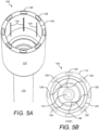
- FIG. 5A and FIG. 5B show a perspective view and a top view, respectively, of the interface portion 110 of the pipette tip 105.
- a set of standoff or spacer features 126 are provided around the upper rim of the interface portion 110 of the pipette tip 105. In one example, eight standoff or spacer features 126 are provided.
- FIG. 6A and FIG. 6B show a perspective view of the distal tip portion (i.e., the tapered tip 118) of the pipette tip 105 and a bottom view of the pipette tip 105, respectively.
- FIG. 7A and FIG. 7B are a side view of the pipette plunger 130 and a perspective view of the plunger upper portion 132 of the pipette plunger 130, respectively.
- FIG. 8A shows again the side view of the pipette plunger 130.
- FIG. 8B and FIG. 8C show perspective views of the distal tip portion 138 of the pipette plunger 130.
- the distal tip portion 138 has a rounded portion 140 that is designed to seal into the opening 116 of the fluid channel 114 (see FIG. 10 and FIG. 11 ).
- the pipette plunger 130 is formed, for example, of polymeric material.
- the polymer used to form the pipette plunger 130 may be the same as or different from the polymer used to form the pipette tip 105.
- FIG. 9A shows again side view of the pipette plunger 130.
- FIG. 9B and FIG. 9C shows a top view and a bottom view, respectively, of the distal tip portion 138 of the pipette plunger 130.
- FIG. 10 , FIG. 11 , and FIG. 12 are close-up cross-sectional views of the distal tip portion 138 of the pipette plunger 130 with respect to the distal tip portion of the pipette tip body 112 of the pipette tip 105.
- the rounded portion 140 of the distal tip portion 138 of the pipette plunger 130 is designed to mate with the opening 116 and the tapered tip 118 at the distal end of the fluid channel 114 of the pipette tip 105, as shown, for example, in FIG. 10 and FIG. 11 .
- the distal tip portion 138 has tapered sidewalls that correspond to the tapered tip 118 of the fluid channel 114.
- an outer upper edge 142 of the distal tip portion 138 of the plunger tip 136 is sized to slideably seal against and along the walls of the fluid channel 114 of the pipette tip body 112.
- the outer upper edge 142 of the distal tip portion 138 of the plunger tip 136 provides a "sealing" ring feature of the pipette plunger 130 that may hold reliable for many mixing cycles before eventually wearing down and leaking.
- FIG. 11 also shows a small void 150 between the tapered tip 118 of the fluid channel 114 and the tapered sidewalls the distal tip portion 138 of the pipette plunger 130.
- aspirating fluid 152 can be trapped within this void 150.
- a beneficial feature of the positive displacement pipette tip 100 is that the design of the distal tip portion 138 of the pipette plunger 130 minimizes the size of the void 150. As a result, the liquid volume being aspirated and/or dispensed can be precisely held. Further, the positive displacement pipette tip 100 can be used with substantially any liquid class range.
- FIG. 12 shows an example of the positive displacement pipette tip 100 when in use.
- FIG. 12 shows the pipette plunger 130 being withdrawn and the aspirating fluid 152 being drawn into the fluid channel 114 of the pipette tip body 112 of the pipette tip 105.
- FIG. 12 shows the pipette plunger 130 being pushed and the dispensing fluid 152 being pushed out of the fluid channel 114 of the pipette tip body 112 of the pipette tip 105.
- positive displacement pipettes may be used to accurately pipette very viscous, volatile, hot or cold, or corrosive samples.
- the presently disclosed positive displacement pipette tip 100 that includes the pipette tip 105 and the pipette plunger 130 is an example of a positive displacement pipette.
- the pipette tip 105 In operation of the presently disclosed positive displacement pipette tip 100 in a liquid handling instrument and/or system, the pipette tip 105 is held fixed while the pipette plunger 130 may be actuated with respect to the pipette tip 105 for aspirating and/or dispensing liquids.
- a benefit of the presently disclosed positive displacement pipette tip 100 is that the pipette tip 105 is designed to be manipulated via a pipette tip clamping mechanism 160 (see FIG. 14 ).
- the pipette tip clamping mechanism 160 for the pipette tip 105 features a pipette tip collet 200, as shown, for example, in FIG. 13 , FIG. 14 , and FIG. 21 .
- the pipette plunger 130 is designed to be manipulated via a pipette plunger clamping mechanism 170 (see FIG. 16C and FIG. 16D ).
- the pipette plunger clamping mechanism 170 for the pipette tip 105 features a plunger collet 300, as shown, for example, in FIG. 15A, FIG. 15B , FIG. 16A, FIG. 16B , and FIG. 22 .
- FIG. 13 is perspective views of an example of the pipette tip collet 200 for use with the pipette tip 105 of the presently disclosed positive displacement pipette tip 100.
- FIG. 14 shows a transparent view of the pipette tip 105 with respect to the pipette tip collet 200 shown in FIG. 13 .
- the pipette tip collet 200 may include, for example, a pipette tip collet upper ring plate 210 and a collet chuck portion 212 for fitting inside the interface portion 110 of the pipette tip 105.
- the collet chuck portion 212 of the pipette tip collet 200 has a serrated feature 214 to increase the friction to the interface portion 110 of the pipette tip 105, as shown, for example, in FIG. 14 .
- the pipette tip collet 200 is a feature component of, for example, a pipette tip clamping mechanism 160, as shown, for example, in FIG. 14 .
- the pipette tip clamping mechanism 160 is an example of a pipette tip clamping mechanism that can be used with the presently disclosed positive displacement pipette tip 100.
- a "collet" is a segmented band or sleeve that can be expanded and/or contracted.
- the collet chuck portion 212 of the pipette tip collet 200 is designed to clamp onto any member surrounding the chuck.
- the collet chuck portion 212 of the pipette tip collet 200 is a segmented band or sleeve for fitting inside the interface portion 110 of the pipette tip 105.
- the collet chuck portion 212 of the pipette tip collet 200 is designed to expand and lock against the inner wall 120 of the interface portion 110 of the pipette tip 105 (see FIG. 14 ). That is, when in the locked position, the collet chuck portion 212 (or clamping chuck) clamps onto the interface portion 110 of the pipette tip 105 that is surrounding the collet chuck portion 212.
- the set of vertical inner wall features 124 of the interface portion 110 of the pipette tip 105 may be used to assist clamping or mating the interface portion 110 of the pipette tip 105 to the collet chuck portion 212 of the pipette tip collet 200. More details of an example of the pipette tip collet 200 are shown and described hereinbelow with reference to FIG. 21 .
- the pipette tip collet 200 is a feature component of the pipette tip clamping mechanism 160. Further, FIG. 14 shows a transparent view of the positive displacement pipette tip 105 with respect to the pipette tip collet 200 shown in FIG. 13 .
- a "collet" is a segmented band or sleeve that can be expanded and/or contracted.
- the collet chuck portion 212 of the pipette tip collet 200 is designed to clamp onto any member surrounding the chuck.
- the collet chuck portion 212 of the pipette tip collet 200 is a segmented band or sleeve for fitting inside the interface portion 110 of the positive displacement pipette tip 105.
- the collet chuck portion 212 of the pipette tip collet 200 is designed to expand and lock against the inner wall 220 of the interface portion 110 of the positive displacement pipette tip 105. That is, when in the locked position, the collet chuck portion 212 (or clamping chuck) clamps onto the interface portion 110 of the positive displacement pipette tip 105 that is surrounding the collet chuck portion 212.
- set of vertical inner wall features 224 of the interface portion 110 of the positive displacement pipette tip 105 and/or the serrated feature 214 of the pipette tip collet 200 may be used to assist clamping or mating the interface portion 110 of the positive displacement pipette tip 105 to the collet chuck portion 212 of the pipette tip collet 200.
- the pipette tip clamping mechanism 160 includes the pipette tip collet 200 and a pipette tip lock mechanism 250.
- the pipette tip lock mechanism 250 may include, for example, a pipette tip lock upper ring plate 252 and a hollow sleeve portion 254 for fitting inside the collet chuck portion 212 of the pipette tip collet 200.
- the collet chuck portion 212 expands against the inside wall 220 of the interface portion 110 of the positive displacement pipette tip 105.
- FIG. 15A is a side view of the plunger collet 300 while FIG. 15B is a cross-sectional view of the plunger collet 300 taken along line A-A of FIG. 15A .
- the plunger collet 300 is for use with the pipette plunger 130 of the presently disclosed positive displacement pipette tip 100.
- the plunger collet 300 may include, for example, a shaft portion 310 and a collet chuck portion 312 for fitting around the plunger upper portion 132 of the pipette plunger 130.
- FIG. 16A shows a perspective view of the collet chuck portion 312 of the pipette plunger 130
- FIG. 16B is a cross-sectional view of the pipette plunger 130 with respect to the collet chuck portion 312 of the plunger collet 300.
- the plunger collet 300 is a feature component of the pipette plunger clamping mechanism 170 (see FIG. 16C and FIG. 16D ).
- the collet chuck portion 312 of the plunger collet 300 is designed to clamp around any member inside the chuck.
- the collet chuck portion 312 of the plunger collet 300 is a segmented band or sleeve for fitting around the plunger upper portion 132 of the pipette plunger 130.
- the collet chuck portion 312 of the plunger collet 300 is designed to expand and lock against the outside wall of the plunger upper portion 132 of the pipette plunger 130 (see FIG. 16B ).
- the collet chuck portion 312 (or clamping chuck) clamps onto the plunger upper portion 132 of the pipette plunger 130 that is inside the collet chuck portion 312.
- the set of vertical outer wall features 133 of the plunger upper portion 132 of the pipette plunger 130 may be used to assist clamping or mating the plunger upper portion 132 to the collet chuck portion 312 of the plunger collet 300. More details of an example of the plunger collet 300 are shown and described hereinbelow with reference to FIG. 22 .
- FIG. 16C and FIG. 16D is an example of a pipette plunger clamping mechanism 170 and a process of clamping a pipette plunger of the presently disclosed positive displacement pipette tip 100.
- the plunger collet 300 is a feature component of the pipette plunger clamping mechanism 170.
- the pipette plunger clamping mechanism 170 includes the plunger collet 300 and a pipette plunger lock mechanism 350.
- the pipette plunger lock mechanism 350 may include, for example, an upper ring plate 352 and a hollow sleeve portion 354 for fitting around the plunger collet 300 including the collet chuck portion 312.
- the collet chuck portion 312 closes against (clamps) the plunger upper portion 132 of the pipette plunger 130.
- the collet chuck portion 312 releases the plunger upper portion 132 of the pipette plunger 130.
- FIG. 16C and FIG. 16D show a pair of the pipette plunger clamping mechanisms 170 installed with respect to two plates (356A and 356B) and with two springs 358 between the two plates (356A and 356B).
- the upper plate 356A is held fixed while each spring 358 provides spring force to a corresponding pipette plunger lock mechanism 350 that passes in slidable (floating) fashion through the lower plate 356B.
- the upper ends of the plunger collet 300 are fixed to the upper plate 356A. Accordingly, the plunger collets 300 are held fixed with respect to the upper plate 356A while the pipette plunger lock mechanisms 350 and the lower plate 356B are moveable with respect to the upper plate 356A. Accordingly, the pipette plunger lock mechanisms 350 are moveable with respect to the plunger collets 300.
- FIG. 16C shows the pipette plunger clamping mechanisms 170 in the non-clamping state.
- the lower plate 356B is pulled upward toward the upper plate 356A, while compressing the two springs 358.
- the hollow sleeve portion 354 of the pipette plunger lock mechanisms 350 is pulled up and away from the collet chuck portion 312 of the plunger collet 300, which allows the plunger collet 300 to open up or expand.
- the pipette plunger 130 may be installed into or removed from the plunger collet 300.
- FIG. 16D shows the pipette plunger clamping mechanisms 170 in the clamping state.
- the spring force of the two springs 358 pushes the lower plate 356B and the pipette plunger lock mechanisms 350 away from the upper plate 356A.
- the hollow sleeve portion 354 pushes down around the collet chuck portion 312 of the plunger collet 300, which causes the plunger collet 300 to close or contract.
- the plunger collet 300 is clamped onto the pipette plunger.
- the pipette plunger clamping mechanism 170 uses the springs 358 to set the locking preload independently, so that each pipette plunger clamping mechanism 170 can handle independently any varying plunger dimensions from one pipette plunger 130 to the next.
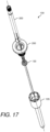
- FIG. 17 and FIG. 18 are exploded views of the plunger collet 300, the pipette tip collet 200, the pipette tip 105, and the pipette plunger 130 of the presently disclosed positive displacement pipette tip 100.
- FIG. 19 are various views showing more details of a non-limiting example of the pipette tip 105 the presently disclosed positive displacement pipette tip 100. All dimensions shown in FIG. 19 are in millimeters. The details of the pipette tip 105 shown in FIG. 19 are exemplary only. The pipette tip 105 is not limited to exact dimensions and features shown in FIG. 19 .
- FIG. 20 is a side view showing more details of a non-limiting example of the pipette plunger 130 the presently disclosed positive displacement pipette tip 100. All dimensions shown in FIG. 20 are in millimeters. The details of the pipette plunger 130 shown in FIG. 20 are exemplary only. The pipette plunger 130 is not limited to exact dimensions and features shown in FIG. 20 .
- FIG. 21 are various views showing more details of a non-limiting example of the pipette tip collet 200 shown in FIG. 13 and FIG. 14 . All dimensions shown in FIG. 21 are in millimeters. The details of the pipette tip collet 200 shown in FIG. 21 are exemplary only. The pipette tip collet 200 is not limited to exact dimensions and features shown in FIG. 21 .
- FIG. 22 are various views showing more details of a non-limiting example of the plunger collet 300 shown in FIG. 15A through FIG. 16B . All dimensions shown in FIG. 22 are in millimeters. The details of the plunger collet 300 shown in FIG. 22 are exemplary only. The plunger collet 300 is not limited to exact dimensions and features shown in FIG. 22 .
- the term "about,” when referring to a value can be meant to encompass variations of, in some embodiments ⁇ 100%, in some embodiments ⁇ 50%, in some embodiments ⁇ 20%, in some embodiments ⁇ 10%, in some embodiments ⁇ 5%, in some embodiments ⁇ 1%, in some embodiments ⁇ 0.5%, and in some embodiments ⁇ 0.1% from the specified amount, as such variations are appropriate to perform the disclosed methods or employ the disclosed compositions.
Claims (13)
- Pointe de pipette (100), comprenant :une pointe de pipette (105) comportant une partie d'interface (110) et un corps de pointe de pipette (112), la partie d'interface (110) comportant une paroi interne (120) et un réceptacle (122), le corps de pointe de pipette (112) comportant un canal de fluide (114) sur la longueur du corps de pointe de pipette (112), le canal de fluide comportant une ouverture (116) au niveau de l'extrémité distale du canal de fluide (114) ; etun piston de pipette (130) positionné le long de l'intérieur de la pointe de pipette (105), le piston de pipette (130) comportant une partie supérieure de piston (132), une partie de centrage de piston (134) et une pointe de piston (136) comportant une partie de pointe distale (138), dans laquelle le réceptacle (122) est adapté pour recevoir la partie de centrage de piston (134), et dans laquelle le canal de fluide (114) est adapté pour recevoir la partie de pointe distale (138) de la pointe de piston (136), dans lequel la partie supérieure de piston (132) comporte une paroi externe ;caractérisée en ce que la paroi externe comprend des caractéristiques verticales de paroi externe (133), dans laquelle les caractéristiques verticales de paroi externe (133) sont configurés pour faciliter le serrage ou l'accouplement de la partie supérieure de piston (132) du piston de pipette (130) à un composant d'accouplement d'un instrument de manipulation de liquides.
- Pointe de pipette (100) selon la revendication 1, dans laquelle le canal de fluide (114) comporte une pointe effilée (118) à l'extrémité distale du canal de fluide (114), et facultativement dans laquelle la partie de pointe distale (138) de la pointe de piston (136) comporte une partie arrondie (140) adaptée pour s'accoupler avec l'ouverture (116) et la pointe effilée (118) à l'extrémité distale du canal de fluide (114), et en outre facultativement, dans laquelle la partie de pointe distale (138) de la pointe de piston (136) comporte des parois latérales effilées correspondant à la pointe effilée (118) du canal de fluide (114), et en outre facultativement, dans laquelle le canal de fluide (114) comporte des parois, la partie de pointe distale (138) de la pointe de piston (136) comportant un bord supérieur externe (142) dimensionné pour assurer une étanchéité coulissante contre et le long des parois du canal de fluide (114) suffisante pour minimiser le vide entre la pointe effilée (118) du canal de fluide (114) et les parois latérales effilées de la partie de pointe distale (138) de la pointe de piston (136), et en outre facultativement, dans laquelle le bord supérieur externe (142) comporte une caractéristique annulaire d'étanchéité formée sur celui-ci.
- Pointe de pipette (100) selon la revendication 1, dans laquelle la pointe de pipette (105) est formée d'un matériau polymère, et facultativement soit :
dans laquelle le piston de pipette (130) est formé du matériau polymère qui est le même que celui de la pointe de pipette (105), ou dans laquelle le piston de pipette (130) est formé d'un matériau polymère qui est différent du matériau polymère de la pointe de pipette (105). - Pointe de pipette (100) selon la revendication 1, dans laquelle la paroi interne de la partie d'interface (110) comprend des caractéristiques verticales de paroi interne (124), et facultativement dans laquelle chacune des caractéristiques verticales de paroi interne (124) est une ligne verticale surélevée ou saillante formée le long de la paroi interne de la partie d'interface (110).
- Pointe de pipette (100) selon la revendication 1, dans laquelle chacune des caractéristiques verticales de paroi externe (133) est une ligne verticale surélevée ou saillante formée le long de la paroi externe de la partie supérieure de piston (132).
- Pointe de pipette (100) selon la revendication 1, dans laquelle la partie d'interface (110) comporte un rebord supérieur avec un ensemble de caractéristiques d'espacement (126).
- Système de manipulation de liquides, comprenant :une pointe de pipette (105) comportant une partie d'interface (110) et un corps de pointe de pipette (112), la partie d'interface (110) comportant une paroi interne (120) et un réceptacle (122), le corps de pointe de pipette comportant un canal de fluide le long de la longueur du corps de pointe de pipette, et le canal de fluide comportant une ouverture au niveau de l'extrémité distale du canal de fluide ;un piston de pipette positionné le long de l'intérieur de la pointe de pipette, le piston de pipette comportant une partie supérieure de piston, une partie de centrage de piston et une pointe de piston comportant une partie de pointe distale, dans lequel le réceptacle est adapté pour recevoir la partie de centrage de piston, (132) comporte une paroi externe, la paroi externe comprenant des caractéristiques verticales de paroi externe (133), dans lequel les caractéristiques verticales de paroi externe (133) sont configurés pour faciliter le serrage ou l'accouplement de la partie supérieure de piston (132) du piston de pipette (130) à un composant d'accouplement d'un instrument de manipulation de liquides, et dans lequel le canal de fluide (114) est adapté pour recevoir la partie de pointe distale (138) de la pointe de piston (136) ; etun mécanisme de serrage de pointe de pipette (160) adapté pour manipuler la pointe de pipette (105) et le piston de pipette (130), dans lequel le mécanisme de serrage de pointe de pipette (160) comprend une pince de pointe de pipette (200) avec une plaque annulaire supérieure (210) et une partie de mandrin à pince (212) destinée à être ajustée à l'intérieur de la partie d'interface (110) de la pointe de pipette (105), et un mécanisme de verrouillage de pointe de pipette (250).
- Système de manipulation de liquides selon la revendication 7, dans lequel la partie de mandrin à pince (212) comporte une caractéristique dentelée (214) adaptée pour augmenter la friction avec la partie d'interface (110) de la pointe de pipette (105).
- Système de manipulation de liquides selon la revendication 8, dans lequel la partie de mandrin à pince (212) est une bande ou un manchon segmenté destiné à être ajusté à l'intérieur de la partie d'interface (110).
- Système de manipulation de liquides selon la revendication 9, dans lequel la partie de mandrin à pince (212) est adaptée pour s'étendre et se verrouiller contre la paroi interne (120) de la partie d'interface (110).
- Système de manipulation de liquide selon la revendication 7, dans lequel le mécanisme de verrouillage de pointe de pipette (250) comprend une plaque annulaire supérieure de verrouillage de pointe de pipette (252) et une partie de manchon creux (254) destinées à être ajustées à l'intérieur de la partie de mandrin à pince (212), et facultativement dans lequel la partie de mandrin à pince (212) est adaptée pour s'étendre contre la paroi interne (120) de la partie d'interface (110) lorsque la partie de manchon creux (254) est ajustée à l'intérieur de la partie de mandrin à pince (212) de la pince de pointe de pipette (200), et dans lequel la partie de mandrin à pince (212) est adaptée pour se rétracter et se détacher par rapport à la partie d'interface (110) lorsque la partie de manchon creux (254) est retirée de la partie de mandrin à pince (212) de la pince de pointe de pipette (200).
- Système de manipulation de liquide selon la revendication 7, comprenant un mécanisme de serrage de piston de pipette (170), dans lequel le mécanisme de serrage de piston de pipette (170) comprend une pince de piston de pipette (300) et un mécanisme de verrouillage de piston de pipette (350), et facultativement dans lequel la pince de piston de pipette (300) comporte une partie d'arbre (310) et une partie de mandrin à pince (312) destinée à être ajustée autour de la partie supérieure de piston (132) du piston de pipette (130), et en outre facultativement, la partie de mandrin à pince (312) est une bande ou un manchon segmenté destiné à être ajusté autour de la partie supérieure de piston (132) du piston de pipette (130), la partie de mandrin à pince (312) étant adaptée pour s'étendre et se verrouiller contre la paroi extérieure de la partie supérieure de piston (132) qui est à l'intérieur de la partie de mandrin à pince (312), et en outre facultativement, dans lequel le mécanisme de verrouillage de piston de pipette (250) comprend une plaque annulaire supérieure (352) et une partie de manchon creux (354) destinée à être ajustée autour de la pince de piston (300), et en outre facultativement dans lequel la partie de mandrin à pince (212) est adaptée pour venir se fermer contre la partie supérieure de piston (132) du piston de pipette (130) lorsque la partie de manchon creux (354) est glissée autour de la partie de mandrin à pince (312) de la pince de piston (300), et dans lequel la partie de mandrin à pince (312) est adaptée pour libérer la partie supérieure de piston (132) du piston de pipette (130) lorsque la partie de manchon creux (354) est retirée de la partie de mandrin à pince (312) de la pince de piston (300).
- Système de manipulation de liquides selon la revendication 7, comprenant un mécanisme de serrage de piston de pipette (170), dans lequel le mécanisme de serrage de piston de pipette (170) comprend une paire de mécanismes de serrage de piston de pipette (170), une paire de pinces de piston de pipette (300), une plaque supérieure fixée (356A), une plaque inférieure (356B) et deux ressorts (358) entre la plaque supérieure (356A) et la plaque inférieure (356B), dans lequel les extrémités supérieures des pinces de piston de pipette (300) sont maintenues fixées à la plaque supérieure (356A), dans lequel la plaque inférieure (356B) et deux ressorts (358) sont mobiles par rapport à la plaque supérieure (356A), et dans lequel chaque ressort (358) est adapté pour fournir une force de ressort à un mécanisme de verrouillage de piston de pipette correspondant (250) qui passe de manière coulissante à travers la plaque inférieure (356B), les mécanismes de verrouillage de piston de pipette (250) sont mobiles par rapport aux pinces de piston (300).
Applications Claiming Priority (2)
| Application Number | Priority Date | Filing Date | Title |
|---|---|---|---|
| US201962797688P | 2019-01-28 | 2019-01-28 | |
| PCT/US2019/069081 WO2020159658A1 (fr) | 2019-01-28 | 2019-12-31 | Pointe de pipette à déplacement positif pour automatisation de commande motorisée ou système d'instrument |
Publications (4)
| Publication Number | Publication Date |
|---|---|
| EP3917671A1 EP3917671A1 (fr) | 2021-12-08 |
| EP3917671A4 EP3917671A4 (fr) | 2022-07-13 |
| EP3917671C0 EP3917671C0 (fr) | 2024-02-21 |
| EP3917671B1 true EP3917671B1 (fr) | 2024-02-21 |
Family
ID=71840243
Family Applications (1)
| Application Number | Title | Priority Date | Filing Date |
|---|---|---|---|
| EP19912823.2A Active EP3917671B1 (fr) | 2019-01-28 | 2019-12-31 | Pointe de pipette à déplacement positif pour automatisation de commande motorisée ou système d'instrument |
Country Status (5)
| Country | Link |
|---|---|
| US (1) | US20220099693A1 (fr) |
| EP (1) | EP3917671B1 (fr) |
| JP (1) | JP2022518067A (fr) |
| CN (1) | CN113613788B (fr) |
| WO (1) | WO2020159658A1 (fr) |
Families Citing this family (5)
| Publication number | Priority date | Publication date | Assignee | Title |
|---|---|---|---|---|
| GB2607890A (en) * | 2021-06-11 | 2022-12-21 | Spt Labtech Ltd | Pipetting head for a liquid dispensing apparatus |
| GB2607893A (en) * | 2021-06-11 | 2022-12-21 | Spt Labtech Ltd | Pipette tip for a liquid dispensing apparatus |
| GB2607892A (en) * | 2021-06-11 | 2022-12-21 | Spt Labtech Ltd | Liquid aspirating or dispensing method and apparatus |
| GB2607891A (en) * | 2021-06-11 | 2022-12-21 | Spt Labtech Ltd | A pipette tip |
| GB2618998A (en) * | 2022-05-25 | 2023-11-29 | Spt Labtech Ltd | Pipetting head for a liquid dispensing apparatus |
Family Cites Families (11)
| Publication number | Priority date | Publication date | Assignee | Title |
|---|---|---|---|---|
| CH671526A5 (fr) * | 1985-12-17 | 1989-09-15 | Hamilton Bonaduz Ag | |
| US5192511A (en) * | 1991-05-31 | 1993-03-09 | Tri-Continent Scientific, Inc. | Pipette tip and piston |
| CN1114831C (zh) * | 1995-03-20 | 2003-07-16 | 准确系统科学株式会社 | 利用吸移管装置处理液体的方法以及用于该法的仪器 |
| US6197259B1 (en) * | 1998-11-06 | 2001-03-06 | Rainin Instrument Co., Inc. | Easy eject pipette tip |
| EP2103680B1 (fr) | 2007-01-19 | 2020-07-01 | Universal Bio Research Co., Ltd. | Appareil destiné au traitement d'une pipette ayant un support/fluide enfermé à l'intérieur et procédé de traitement d'une pipette ayant un support/fluide enfermé à l'intérieur |
| WO2013043203A2 (fr) * | 2011-09-25 | 2013-03-28 | Theranos, Inc. | Systèmes et procédés pour analyse multifonction |
| US9664702B2 (en) * | 2011-09-25 | 2017-05-30 | Theranos, Inc. | Fluid handling apparatus and configurations |
| TWI583419B (zh) * | 2012-03-23 | 2017-05-21 | 沃爾夫拓利醫療有限公司 | 自動失效注射器組合 |
| FR3012883B1 (fr) * | 2013-11-07 | 2015-12-25 | Gilson Sas | Systeme de pipetage a deplacement positif, presentant une conception facilitant la prehension du piston de l'ensemble capillaire-piston |
| CN104001563B (zh) * | 2014-06-09 | 2015-07-08 | 上海优爱宝机器人技术有限公司 | 移液器 |
| CN109562372A (zh) * | 2016-06-15 | 2019-04-02 | 汉密尔顿公司 | 移液装置、移液管末梢联接器和移液管末梢:装置和方法 |
-
2019
- 2019-12-31 JP JP2021543454A patent/JP2022518067A/ja active Pending
- 2019-12-31 CN CN201980093340.4A patent/CN113613788B/zh active Active
- 2019-12-31 WO PCT/US2019/069081 patent/WO2020159658A1/fr unknown
- 2019-12-31 EP EP19912823.2A patent/EP3917671B1/fr active Active
- 2019-12-31 US US17/426,235 patent/US20220099693A1/en active Pending
Also Published As
| Publication number | Publication date |
|---|---|
| CN113613788B (zh) | 2023-11-14 |
| WO2020159658A1 (fr) | 2020-08-06 |
| EP3917671A1 (fr) | 2021-12-08 |
| EP3917671A4 (fr) | 2022-07-13 |
| CN113613788A (zh) | 2021-11-05 |
| JP2022518067A (ja) | 2022-03-11 |
| EP3917671C0 (fr) | 2024-02-21 |
| US20220099693A1 (en) | 2022-03-31 |
Similar Documents
| Publication | Publication Date | Title |
|---|---|---|
| EP3917671B1 (fr) | Pointe de pipette à déplacement positif pour automatisation de commande motorisée ou système d'instrument | |
| US5192511A (en) | Pipette tip and piston | |
| EP2914380B1 (fr) | Dispositif de type système de pipetage | |
| US9079178B2 (en) | Apparatus and methods for pipetting with interchangeability among different pipette tips | |
| US20220091147A1 (en) | Liquid handling instrument and pipetting head for and method of aspirating and/or dispensing liquids | |
| EP0982072B1 (fr) | Embout pour un dispositif d'aspiration | |
| US10137445B2 (en) | Single use capillary micropipette for dispensing a defined volume of a liquid | |
| US20230110524A1 (en) | Pipette for use with a pipette tip and pipette tip line comprising several pipette tips of different types for use with a pipette | |
| JP7431805B2 (ja) | 大小容量精密ピペッタ | |
| US7475916B2 (en) | Device and method for coupling lines to fluidic microsystems | |
| CN111408422B (zh) | 用于与移液器末端件一起使用的移液器 | |
| EP1047928B1 (fr) | Seringue d'echantillonneur automatique a fermeture par compression | |
| EP1688180B1 (fr) | Pipette à pointes jetables de tailles différentes | |
| JP2018534535A (ja) | 例えば核酸を抽出するための機器から、少なくとも一つの生成物排出管を、当該生成物を受け取る手段に接続する装置、接続するための装置 | |
| US20180221864A1 (en) | Pipette Tip Loading and Unloading Mechanism for Single Row Multichannel Pipettors | |
| EP3956672A1 (fr) | Dispositif microfluidique intégré avec adaptation de pipette | |
| US20230128571A1 (en) | Large volume separation system | |
| US10758901B2 (en) | Apparatus, system and method for filtering liquid samples | |
| JP2006507106A (ja) | 改良されたピペッタ及び外部にシールが設けられたピペット |
Legal Events
| Date | Code | Title | Description |
|---|---|---|---|
| STAA | Information on the status of an ep patent application or granted ep patent |
Free format text: STATUS: THE INTERNATIONAL PUBLICATION HAS BEEN MADE |
|
| PUAI | Public reference made under article 153(3) epc to a published international application that has entered the european phase |
Free format text: ORIGINAL CODE: 0009012 |
|
| STAA | Information on the status of an ep patent application or granted ep patent |
Free format text: STATUS: REQUEST FOR EXAMINATION WAS MADE |
|
| 17P | Request for examination filed |
Effective date: 20210803 |
|
| AK | Designated contracting states |
Kind code of ref document: A1 Designated state(s): AL AT BE BG CH CY CZ DE DK EE ES FI FR GB GR HR HU IE IS IT LI LT LU LV MC MK MT NL NO PL PT RO RS SE SI SK SM TR |
|
| RIC1 | Information provided on ipc code assigned before grant |
Ipc: G01N 35/10 20060101ALI20220126BHEP Ipc: G01F 11/02 20060101ALI20220126BHEP Ipc: G01N 1/14 20060101ALI20220126BHEP Ipc: B01L 3/02 20060101AFI20220126BHEP |
|
| DAV | Request for validation of the european patent (deleted) | ||
| DAX | Request for extension of the european patent (deleted) | ||
| A4 | Supplementary search report drawn up and despatched |
Effective date: 20220614 |
|
| RIC1 | Information provided on ipc code assigned before grant |
Ipc: G01N 35/10 20060101ALI20220609BHEP Ipc: G01F 11/02 20060101ALI20220609BHEP Ipc: G01N 1/14 20060101ALI20220609BHEP Ipc: B01L 3/02 20060101AFI20220609BHEP |
|
| GRAP | Despatch of communication of intention to grant a patent |
Free format text: ORIGINAL CODE: EPIDOSNIGR1 |
|
| STAA | Information on the status of an ep patent application or granted ep patent |
Free format text: STATUS: GRANT OF PATENT IS INTENDED |
|
| RAP1 | Party data changed (applicant data changed or rights of an application transferred) |
Owner name: FORMULATRIX INTERNATIONAL HOLDING LTD |
|
| INTG | Intention to grant announced |
Effective date: 20230908 |
|
| GRAS | Grant fee paid |
Free format text: ORIGINAL CODE: EPIDOSNIGR3 |
|
| GRAA | (expected) grant |
Free format text: ORIGINAL CODE: 0009210 |
|
| STAA | Information on the status of an ep patent application or granted ep patent |
Free format text: STATUS: THE PATENT HAS BEEN GRANTED |
|
| AK | Designated contracting states |
Kind code of ref document: B1 Designated state(s): AL AT BE BG CH CY CZ DE DK EE ES FI FR GB GR HR HU IE IS IT LI LT LU LV MC MK MT NL NO PL PT RO RS SE SI SK SM TR |
|
| REG | Reference to a national code |
Ref country code: GB Ref legal event code: FG4D |
|
| REG | Reference to a national code |
Ref country code: CH Ref legal event code: EP |
|
| REG | Reference to a national code |
Ref country code: IE Ref legal event code: FG4D |
|
| REG | Reference to a national code |
Ref country code: DE Ref legal event code: R096 Ref document number: 602019047132 Country of ref document: DE |
|
| U01 | Request for unitary effect filed |
Effective date: 20240319 |
|
| U07 | Unitary effect registered |
Designated state(s): AT BE BG DE DK EE FI FR IT LT LU LV MT NL PT SE SI Effective date: 20240327 |