EP3154698B1 - Pipette comprenant un élément de dispositif d'imagerie - Google Patents
Pipette comprenant un élément de dispositif d'imagerie Download PDFInfo
- Publication number
- EP3154698B1 EP3154698B1 EP15731387.5A EP15731387A EP3154698B1 EP 3154698 B1 EP3154698 B1 EP 3154698B1 EP 15731387 A EP15731387 A EP 15731387A EP 3154698 B1 EP3154698 B1 EP 3154698B1
- Authority
- EP
- European Patent Office
- Prior art keywords
- pipette
- imaging device
- device element
- tip
- image
- Prior art date
- Legal status (The legal status is an assumption and is not a legal conclusion. Google has not performed a legal analysis and makes no representation as to the accuracy of the status listed.)
- Active
Links
Images


Classifications
-
- B—PERFORMING OPERATIONS; TRANSPORTING
- B01—PHYSICAL OR CHEMICAL PROCESSES OR APPARATUS IN GENERAL
- B01L—CHEMICAL OR PHYSICAL LABORATORY APPARATUS FOR GENERAL USE
- B01L3/00—Containers or dishes for laboratory use, e.g. laboratory glassware; Droppers
- B01L3/02—Burettes; Pipettes
- B01L3/021—Pipettes, i.e. with only one conduit for withdrawing and redistributing liquids
- B01L3/0217—Pipettes, i.e. with only one conduit for withdrawing and redistributing liquids of the plunger pump type
- B01L3/0237—Details of electronic control, e.g. relating to user interface
-
- G—PHYSICS
- G01—MEASURING; TESTING
- G01N—INVESTIGATING OR ANALYSING MATERIALS BY DETERMINING THEIR CHEMICAL OR PHYSICAL PROPERTIES
- G01N35/00—Automatic analysis not limited to methods or materials provided for in any single one of groups G01N1/00 - G01N33/00; Handling materials therefor
- G01N35/10—Devices for transferring samples or any liquids to, in, or from, the analysis apparatus, e.g. suction devices, injection devices
- G01N35/1009—Characterised by arrangements for controlling the aspiration or dispense of liquids
- G01N35/1011—Control of the position or alignment of the transfer device
-
- G—PHYSICS
- G02—OPTICS
- G02B—OPTICAL ELEMENTS, SYSTEMS OR APPARATUS
- G02B27/00—Optical systems or apparatus not provided for by any of the groups G02B1/00 - G02B26/00, G02B30/00
- G02B27/02—Viewing or reading apparatus
- G02B27/028—Viewing or reading apparatus characterised by the supporting structure
-
- H—ELECTRICITY
- H04—ELECTRIC COMMUNICATION TECHNIQUE
- H04N—PICTORIAL COMMUNICATION, e.g. TELEVISION
- H04N23/00—Cameras or camera modules comprising electronic image sensors; Control thereof
- H04N23/60—Control of cameras or camera modules
- H04N23/63—Control of cameras or camera modules by using electronic viewfinders
-
- H—ELECTRICITY
- H04—ELECTRIC COMMUNICATION TECHNIQUE
- H04N—PICTORIAL COMMUNICATION, e.g. TELEVISION
- H04N7/00—Television systems
- H04N7/18—Closed-circuit television [CCTV] systems, i.e. systems in which the video signal is not broadcast
-
- B—PERFORMING OPERATIONS; TRANSPORTING
- B01—PHYSICAL OR CHEMICAL PROCESSES OR APPARATUS IN GENERAL
- B01L—CHEMICAL OR PHYSICAL LABORATORY APPARATUS FOR GENERAL USE
- B01L2200/00—Solutions for specific problems relating to chemical or physical laboratory apparatus
- B01L2200/14—Process control and prevention of errors
- B01L2200/143—Quality control, feedback systems
-
- B—PERFORMING OPERATIONS; TRANSPORTING
- B01—PHYSICAL OR CHEMICAL PROCESSES OR APPARATUS IN GENERAL
- B01L—CHEMICAL OR PHYSICAL LABORATORY APPARATUS FOR GENERAL USE
- B01L2300/00—Additional constructional details
- B01L2300/02—Identification, exchange or storage of information
- B01L2300/021—Identification, e.g. bar codes
-
- B—PERFORMING OPERATIONS; TRANSPORTING
- B01—PHYSICAL OR CHEMICAL PROCESSES OR APPARATUS IN GENERAL
- B01L—CHEMICAL OR PHYSICAL LABORATORY APPARATUS FOR GENERAL USE
- B01L2300/00—Additional constructional details
- B01L2300/02—Identification, exchange or storage of information
- B01L2300/025—Displaying results or values with integrated means
- B01L2300/027—Digital display, e.g. LCD, LED
-
- B—PERFORMING OPERATIONS; TRANSPORTING
- B01—PHYSICAL OR CHEMICAL PROCESSES OR APPARATUS IN GENERAL
- B01L—CHEMICAL OR PHYSICAL LABORATORY APPARATUS FOR GENERAL USE
- B01L2300/00—Additional constructional details
- B01L2300/06—Auxiliary integrated devices, integrated components
- B01L2300/0627—Sensor or part of a sensor is integrated
- B01L2300/0654—Lenses; Optical fibres
Definitions
- the present invention relates to a hand-held pipette intended for use in the dosage of liquids.
- Pipettes used for liquid dosage in laboratories typically comprise a piston movable in a cylinder for aspiration of liquid into a tip connected with the cylinder.
- Such pipettes comprise an elongated handle held by palm grip.
- the volume is usually adjustable.
- There also multichannel pipettes comprising e.g. eight channels in a row.
- the piston in almost all manual pipettes is moved by pushing with thumb a spring loaded rod placed at the upper end of the pipette. Volume is usually set by rotating the knob.
- the detachable tip is removed by pushing a spring loaded push button at the side of the handle.
- Electronic pipettes in which the piston is actuated by means of an electric motor and a control system associated with it.
- the tip removal mechanism is still often manual, but there are also electronic pipettes in which also the tip removal mechanism is electrically driven.
- pistons are actuated by manual force and which comprise an electronic display only.
- Electronic pipettes have a user interface for selection of the desired pipetting function (e.g. direct or reverse pipetting), setting of the volume and for giving commands for performing operations.
- the user interface has the necessary switches for input of the necessary settings and performance of the functions.
- the user interface is connected to a display, by means of which the volume and other necessary data can be displayed.
- the display can also show menus allowing data input in the control system.
- WO 2012/069925 A1 discloses devices and methods for programmable manipulation of pipettes.
- a liquid handling android comprising a robot arm is used for manipulating manual pipettes.
- the robot arm is provided with a camera, which can image a tip of a pipette.
- WO 2006/111977 A2 discloses a pipette with a fluid volume sensor.
- the fluid volume sensor may be a miniature CCD camera mounted to the pipette.
- a hand-held pipette comprises a cylinder with a piston movable inside the cylinder for aspiring and dispensing liquid, at least one tip, a handle portion for gripping the pipette, and an imaging device element for obtaining at least one image that assists the user of the pipette.
- the imaging device of the imaging device element is focused at the area in front of the at least one tip of the pipette and/or at the at least one tip of the pipette.
- the imaging device of the imaging device element When the imaging device of the imaging device element is focused at the area in front of the tip or tips of the pipette, the image provided may be used to guide the pipetting process more precisely, especially when the image shown is magnified view, for example.
- the image can be used to help in inserting pipette's tip or tips correctly in small vessels or depressions for aspiring or dispensing small amounts of liquid.
- the at least one imaging device element is able to monitor the workflow relating to the use of the pipette.
- the imaging device element may be as a fixed part of the pipette, especially in electronic pipettes, or the imaging device element may be separate module attachable on the pipette, whereby the imaging device element can also be used with manual pipettes without an electronic control system and related interface for operating the pipette.
- a pipette is in this context a hand-held entity.
- the pipette may be used at laboratories for handling liquid samples.
- the pipette preferably comprises a detachable tip or tip container into which liquid is aspired and from which the liquid is dispensed, connected detachably to the body of the pipette.
- An imaging device element is in this context a suitable small-sized device for obtaining image, preferably in digital form, either as a snapshot of as a continuous image feed, and for forwarding the obtained image to a suitable viewing or analyzing device.
- the imaging device element can be a single structural element or it can be broken down to a separate parts located at different places in the pipette of the invention. Examples of the imaging device element are digital cameras, such as disclosed in publications US 2014/0009631 A1 and US 7,873,269 B2 .
- the imaging device element can be used to provide continuous image feed to a suitable display or it can be used to take snapshot images.
- the continuous image feed is helpful for guiding the actual pipetting operations, for example.
- the snapshot images can be used for inspection purposes, for example.
- the pipette according to the invention is advantageously provided with integrated or separate display for displaying and viewing the image from the imaging device element.
- the pipette's own display which may be part of the interface of the electronic pipette, may be used for viewing the image from the imaging device element.
- the image from the imaging device element may be viewed in separate display, to which the image from the imaging device element is send by cable or wirelessly, for example.
- the pipette according to the invention is an electronic pipette comprising a motor for moving the piston inside the cylinder, a control system for carrying out pipette operations, and a user interface for operating the pipette.
- the imaging device element can easily be integrated, and incorporated as a functional component operating and operated through the user interface of the pipette.
- the pipette according to the invention is advantageously equipped with image recognition, which can be used to provide different types of automatic warnings and confirmations.
- image recognition can be used to recognize whether any liquid is left in the pipette's tip, or if there is a filter missing in the tip etc.
- the image recognition can also be used to identify the tip used in the pipette, and this information may be used to set corresponding parameters for the pipette.
- the pipette's imaging device element can be used to read bar codes or QR codes (Quick Response codes), whereby settings and/or standard work rotations can be easily input in the control system of the pipette.
- the imaging device element may be connected, or be part of, the handle part or portion of the pipette.
- the imaging device element may be connected to the pipette via bendable fiber optics wire, which allows easy adjustment of focus area of the digital device element.
- the digital imaging device element may comprise a digital camera as the imaging device of the imaging device element.
- the electronic pipette 1 of the invention shown in figures 1A-1C is formed as a handheld entity and the body of which comprises handle portion 2, at upper end of the handle portion tilted display portion 3, and at lower end of the handle portion tip portion 4 of the pipette.
- the pipette 1 When the pipette 1 is used it is gripped from the handle portion 2 so that middle finger of the user sets against finger support 5 at the upper part of the handle portion, which leaves index finger of the user free to operate the operating switch 6 of the pipette.
- To the tip portion 4 is attached detachable pipette tip 7, to which liquid is aspired and from which liquid is dispensed during the use of the pipette 1.
- the outer surface of the display portion 3 of the pipette 1 is equipped with a display 8 and operation keys 9, which form the user interface of operating system of the pipette together with the operating switch 6.
- a cylinder 10 Inside the body of the pipette 1, extending in the area of the handle portion 2 and the tip portion 4 of the pipette, is located a cylinder 10 and inside the cylinder piston 11 movable with respect to the cylinder, which both extend along or parallel with the central axis of the handle portion and/or tip portion of the pipette. From the lower end of the cylinder 11 extends a channel 12 at the bottom end surface of the tip portion 4 for obtaining aspiration and dispensing of liquid to and from the detachable pipette tip 7 by moving the piston 11 inside the cylinder 10. Between surfaces of the cylinder 10 and the piston 11 is located a spring member 13 extending in the length direction of the cylinder and piston for supporting a sealing o-ring 20 between the cylinder and the piston.
- the means for moving the piston 11 comprises a linear actuator formed by a threaded rod 14, which extends along or parallel with the central axis of the handle portion 2, and an electric motor 15, which moves the threaded rod in its lengthwise direction through a threaded connection between the unrotating threaded rod and a rotating member of the motor.
- a linear actuator formed by a threaded rod 14, which extends along or parallel with the central axis of the handle portion 2, and an electric motor 15, which moves the threaded rod in its lengthwise direction through a threaded connection between the unrotating threaded rod and a rotating member of the motor.
- a protrusion 17 inside which is set an imaging device element 16, which is able to provide a picture or live feed to the pipette's 1 display 8 and/or save the picture or live feed to the memory of the pipette's electronic control system.
- the imaging device element 16 can be a single unit, such as a digital camera unit, or it can have an optical lens and an optic fiber to transfer the optical image to a separate optical imaging sensor 18 (e.g. CCD, Charge-Coupled Device), which is preferably located on the electric circuit board of the control system.
- the picture may also be transferred with a cable or wirelessly to an external display.
- the imaging device element 16 is positioned and aimed so, that it shows the pipette tip 7 and area in front of it ( figure 1C ).
- the image or image feed from the imaging device element 16 can be used to help the correct positioning of the pipette tip 7. Further, the thus obtained image feed can be used to detect any leftover liquid in the pipette tip 7 or if there are any other problems with the pipette tip, for example.
- These detection actions can also be implemented automatically by analyzing the image feed from the imaging device element 16 with the electronic operating system.
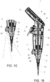
- FIG 2 shows an alternative embodiment of an electronic pipette 21 according to the present invention, where the pipette is otherwise similar than one presented in figures 1A-1C , and the same reference numerals are used for the same parts, with the exception of the connection of the imaging device element 16.
- the imaging device element 16 is connected to the lower part of the handle portion 2 with a bendable fiber optics wire 22.
- the bendable fiber optics wire 22 allows free positioning and aiming of the imaging device element 16 so that it can be adjusted to be suitable for different applications and for different pipette tips 7, for example.
- FIG 3 shows an example of a functional diagram of an electronic pipette, like the pipettes shown in figures 1A-1C and 2 .
- the operations of the pipette are controlled with a central processing unit (CPU), which is equipped with memory for storing pre-programmed operations and functions.
- CPU central processing unit
- the user gives commands to the CPU through operation keys and selections and information displayed in a display.
- the CPU is supplied with operating power by a battery and a voltage regulator, which can be recharged with a changer through charging connections when the pipette is placed in its stand.
- the CPU of the pipette can also be connected to external databases through data interface.
- the CPU receives information from and controls the pipette's piston home position detector.
- the CPU controls the motor of the pipette through a motor driver.
- the CPU controls a digital camera based on user's input commands, carries out required digital detection and recognition actions, and saves the digital image feed from the camera either to its memory or to external database through data interface.
- the memory of the pipette may also include a detachable memory module (not shown), such as memory cards, for storing the digital image feed or snapshot images.
- the CPU also gives alerts through a buzzer in preset situations, or when the CPU notices a problem in a pipetting operation, for example.
- the dashed line in figure 3 presents boundary surface between the pipette itself and the stand of the pipette in which the pipette is placed when not in use.
Claims (7)
- Pipette portative (1, 21) comprenant un cylindre (10) doté d'un piston (11) déplaçable à l'intérieur du cylindre conçu pour aspirer et délivrer le liquide, au moins une pointe (7), une partie de poignée (2) pour assurer la préhension de la pipette et un élément de dispositif d'imagerie (16) de manière à obtenir au moins une image aidant l'utilisateur de la pipette, caractérisé en ce que le dispositif d'imagerie de l'élément de dispositif d'imagerie (16) est focalisé au niveau de la région à l'avant de l'au moins une pointe (7) de la pipette (1, 21) et/ou au niveau d'au moins une pointe (7) de la pipette (1, 21).
- Pipette (1, 21) selon la revendication 1, dans laquelle l'élément de dispositif d'imagerie (16) est conçu pour assurer une alimentation d'images en continu et/ou des images instantanées.
- Pipette (1, 21) selon la revendication 1 ou 2, dans laquelle la pipette comprend un afficheur intégré ou séparé (8) de manière à visualiser l'image depuis l'élément de dispositif d'imagerie (16).
- Pipette (1, 21) selon l'une quelconque des revendications 1 à 3, dans laquelle la pipette est une pipette électronique (1, 21) comprenant un moteur (15) pour déplacer le piston (11) à l'intérieur du cylindre (10), un système de commande pour exécuter les opérations de pipette et une interface utilisateur (6, 8, 9) pour actionner la pipette.
- Pipette (1, 21) selon la revendication 4, dans laquelle l'élément de dispositif d'imagerie (16), un afficheur (8) visualisant l'image depuis l'élément de dispositif d'imagerie ou le système de commande de la pipette électronique (1, 21) est muni d'une reconnaissance d'images.
- Pipette (1, 21) selon l'une quelconque des revendications 1 à 5, dans laquelle l'élément de dispositif d'imagerie (16) est relié à la poignée (2) de la pipette ou l'élément de dispositif d'imagerie est relié à la pipette par un câble flexible de fibres optiques (19).
- Pipette (1, 21) selon l'une quelconque des revendications 1 à 6, dans laquelle l'élément de dispositif d'imagerie (16) comprend une caméra numérique en tant que dispositif d'imagerie de l'élément de dispositif d'imagerie.
Applications Claiming Priority (2)
| Application Number | Priority Date | Filing Date | Title |
|---|---|---|---|
| FI20145531 | 2014-06-10 | ||
| PCT/FI2015/050388 WO2015189464A1 (fr) | 2014-06-10 | 2015-06-05 | Pipette comprenant un élément de dispositif d'imagerie |
Publications (2)
| Publication Number | Publication Date |
|---|---|
| EP3154698A1 EP3154698A1 (fr) | 2017-04-19 |
| EP3154698B1 true EP3154698B1 (fr) | 2019-02-06 |
Family
ID=53487384
Family Applications (1)
| Application Number | Title | Priority Date | Filing Date |
|---|---|---|---|
| EP15731387.5A Active EP3154698B1 (fr) | 2014-06-10 | 2015-06-05 | Pipette comprenant un élément de dispositif d'imagerie |
Country Status (5)
| Country | Link |
|---|---|
| US (2) | US10112192B2 (fr) |
| EP (1) | EP3154698B1 (fr) |
| CN (1) | CN106660046B (fr) |
| ES (1) | ES2713692T3 (fr) |
| WO (1) | WO2015189464A1 (fr) |
Cited By (1)
| Publication number | Priority date | Publication date | Assignee | Title |
|---|---|---|---|---|
| DE102020208740A1 (de) | 2020-07-13 | 2022-01-13 | Fraunhofer-Gesellschaft zur Förderung der angewandten Forschung eingetragener Verein | Verfahren zur Ermittlung einer Absolutkoordinate für ein Ziel-Well einer Multiwellplatte sowie Adressierungseinrichtung |
Families Citing this family (8)
| Publication number | Priority date | Publication date | Assignee | Title |
|---|---|---|---|---|
| JP6781919B2 (ja) | 2014-09-03 | 2020-11-11 | 国立研究開発法人産業技術総合研究所 | 電動ピペットシステム、電動ピペット及び作業手順表示装置 |
| JP6842242B2 (ja) * | 2016-03-22 | 2021-03-17 | 株式会社アイカムス・ラボ | 分注システム |
| EP3581275B1 (fr) * | 2016-06-15 | 2022-08-10 | Hamilton Company | Assemblage de coupleur de pointe de pipette et pointe de pipette |
| USD871606S1 (en) * | 2017-11-22 | 2019-12-31 | Brand Gmbh + Co Kg | Hand operated laboratory instrument |
| US20210181222A1 (en) * | 2018-04-23 | 2021-06-17 | Shimadzu Corporation | Autosampler |
| EP3756766A1 (fr) * | 2019-06-28 | 2020-12-30 | Sartorius Biohit Liquid Handling Oy | Procédé de transmission d'informations, dispositif de manipulation de liquide et système |
| US11660592B2 (en) | 2020-02-14 | 2023-05-30 | DeNovix, Inc. | Dynamic broad volumetric range pipette |
| CN113976198A (zh) * | 2021-10-29 | 2022-01-28 | 美东汇成生命科技(昆山)有限公司 | 一种多功能移液吸头 |
Citations (5)
| Publication number | Priority date | Publication date | Assignee | Title |
|---|---|---|---|---|
| EP1243929A1 (fr) | 1999-12-28 | 2002-09-25 | Precision System Science Co., Ltd. | Dispositif de controle de fonctionnement et procede de controle de distributeur |
| WO2005079989A1 (fr) | 2004-02-25 | 2005-09-01 | Thermo Electron Oy | Pipette electronique |
| US7537735B2 (en) | 2004-05-21 | 2009-05-26 | Biomerieux, Inc. | Aspirator systems having an aspirator tip optical level detector and methods for using the same |
| WO2009130309A1 (fr) | 2008-04-24 | 2009-10-29 | bioMérieux B.V. | Procédé et appareil pour vérifier le fluide dans une pointe de pipette |
| WO2012069925A1 (fr) | 2010-11-23 | 2012-05-31 | Andrew Alliance S.A | Dispositifs et procédés pour manipulation programmable de pipettes |
Family Cites Families (11)
| Publication number | Priority date | Publication date | Assignee | Title |
|---|---|---|---|---|
| FI64752C (fi) | 1982-06-29 | 1984-01-10 | Labsystems Oy | Volymreglerbar pipett |
| JP4021335B2 (ja) | 2003-01-31 | 2007-12-12 | ユニバーサル・バイオ・リサーチ株式会社 | 監視機能付分注装置および分注装置の監視方法 |
| FI20031683A0 (fi) | 2003-11-19 | 2003-11-19 | Thermo Electron Oy | Pipetti jossa on kärjenpoistomekanismi |
| FR2862888B1 (fr) * | 2003-11-27 | 2006-07-07 | Gilson Sas | Procede d'affichage d'une valeur d'un volume d'un echantillon liquide a prelever avec une pipette, a precision amelioree |
| FI20040289A0 (fi) | 2004-02-25 | 2004-02-25 | Thermo Electron Oy | Ohjattava pipetti |
| US20090055131A1 (en) * | 2005-04-20 | 2009-02-26 | Shmuel Bukshpan | Automatic recording volume measurement apparatus |
| US7469100B2 (en) | 2005-10-03 | 2008-12-23 | Flextronics Ap Llc | Micro camera module with discrete manual focal positions |
| WO2010123951A1 (fr) | 2009-04-22 | 2010-10-28 | University Of North Carolina At Charlotte | Dispositif de distribution de liquide guidé par un faisceau lumineux |
| US9782769B2 (en) | 2009-04-22 | 2017-10-10 | The University Of North Carolina At Charlotte | Light beam guided liquid delivery device |
| DE102012102918A1 (de) | 2012-04-03 | 2013-10-10 | Eppendorf Ag | Laborgerätesystem und Laborgerät zum Behandeln von Fluiden und Feststoffen sowie Verfahren zum Betreiben eines Laborgerätes |
| US9134503B2 (en) | 2012-07-06 | 2015-09-15 | Apple Inc. | VCM OIS actuator module |
-
2015
- 2015-06-05 CN CN201580042844.5A patent/CN106660046B/zh active Active
- 2015-06-05 WO PCT/FI2015/050388 patent/WO2015189464A1/fr active Application Filing
- 2015-06-05 US US15/317,481 patent/US10112192B2/en active Active
- 2015-06-05 ES ES15731387T patent/ES2713692T3/es active Active
- 2015-06-05 EP EP15731387.5A patent/EP3154698B1/fr active Active
-
2018
- 2018-09-28 US US16/145,380 patent/US10350589B2/en active Active
Patent Citations (5)
| Publication number | Priority date | Publication date | Assignee | Title |
|---|---|---|---|---|
| EP1243929A1 (fr) | 1999-12-28 | 2002-09-25 | Precision System Science Co., Ltd. | Dispositif de controle de fonctionnement et procede de controle de distributeur |
| WO2005079989A1 (fr) | 2004-02-25 | 2005-09-01 | Thermo Electron Oy | Pipette electronique |
| US7537735B2 (en) | 2004-05-21 | 2009-05-26 | Biomerieux, Inc. | Aspirator systems having an aspirator tip optical level detector and methods for using the same |
| WO2009130309A1 (fr) | 2008-04-24 | 2009-10-29 | bioMérieux B.V. | Procédé et appareil pour vérifier le fluide dans une pointe de pipette |
| WO2012069925A1 (fr) | 2010-11-23 | 2012-05-31 | Andrew Alliance S.A | Dispositifs et procédés pour manipulation programmable de pipettes |
Cited By (2)
| Publication number | Priority date | Publication date | Assignee | Title |
|---|---|---|---|---|
| DE102020208740A1 (de) | 2020-07-13 | 2022-01-13 | Fraunhofer-Gesellschaft zur Förderung der angewandten Forschung eingetragener Verein | Verfahren zur Ermittlung einer Absolutkoordinate für ein Ziel-Well einer Multiwellplatte sowie Adressierungseinrichtung |
| WO2022013106A1 (fr) | 2020-07-13 | 2022-01-20 | Fraunhofer-Gesellschaft zur Förderung der angewandten Forschung e.V. | Procédé de détermination d'une coordonnée absolue pour un puits cible d'une plaque à puits multiples et dispositif d'adressage |
Also Published As
| Publication number | Publication date |
|---|---|
| ES2713692T3 (es) | 2019-05-23 |
| US20170120235A1 (en) | 2017-05-04 |
| WO2015189464A1 (fr) | 2015-12-17 |
| US10112192B2 (en) | 2018-10-30 |
| CN106660046A (zh) | 2017-05-10 |
| US20190030525A1 (en) | 2019-01-31 |
| US10350589B2 (en) | 2019-07-16 |
| EP3154698A1 (fr) | 2017-04-19 |
| CN106660046B (zh) | 2019-09-13 |
Similar Documents
| Publication | Publication Date | Title |
|---|---|---|
| US10350589B2 (en) | Pipette comprising imaging device element | |
| US10105698B2 (en) | Pipette with a tracking system | |
| JP6585109B2 (ja) | ピペットのプログラミング可能な操作のための方法 | |
| EP3222354A1 (fr) | Système de pipetage | |
| JP6735475B2 (ja) | ピペット装置及び液体処理システム | |
| EP3474994A1 (fr) | Pipette de vérification et appareil de vision | |
| US9321048B2 (en) | Sample distribution system and process | |
| JP2004264044A (ja) | 監視機能付分注装置および分注装置の監視方法 | |
| JP2023029508A (ja) | ピストンストロークピペットを駆動する方法、ピストンストロークピペット、データ処理装置及びシステム | |
| WO2021193427A1 (fr) | Procédé de stockage d'écouvillon médical et dispositif de stockage d'écouvillon médical | |
| EP2324925B1 (fr) | Pipette ou distributeur avec un indicateur de la position du piston | |
| EP4177330A1 (fr) | Dispositif de récupération de cellules | |
| JP2023045793A (ja) | 顕微鏡補助装置、顕微鏡補助装置の制御方法、及びプログラム | |
| JP2019078904A (ja) | 顕微鏡システム | |
| WO2014184428A1 (fr) | Pipette multicanaux |
Legal Events
| Date | Code | Title | Description |
|---|---|---|---|
| STAA | Information on the status of an ep patent application or granted ep patent |
Free format text: STATUS: THE INTERNATIONAL PUBLICATION HAS BEEN MADE |
|
| PUAI | Public reference made under article 153(3) epc to a published international application that has entered the european phase |
Free format text: ORIGINAL CODE: 0009012 |
|
| STAA | Information on the status of an ep patent application or granted ep patent |
Free format text: STATUS: REQUEST FOR EXAMINATION WAS MADE |
|
| 17P | Request for examination filed |
Effective date: 20170109 |
|
| AK | Designated contracting states |
Kind code of ref document: A1 Designated state(s): AL AT BE BG CH CY CZ DE DK EE ES FI FR GB GR HR HU IE IS IT LI LT LU LV MC MK MT NL NO PL PT RO RS SE SI SK SM TR |
|
| AX | Request for extension of the european patent |
Extension state: BA ME |
|
| DAV | Request for validation of the european patent (deleted) | ||
| DAX | Request for extension of the european patent (deleted) | ||
| STAA | Information on the status of an ep patent application or granted ep patent |
Free format text: STATUS: EXAMINATION IS IN PROGRESS |
|
| 17Q | First examination report despatched |
Effective date: 20180316 |
|
| GRAP | Despatch of communication of intention to grant a patent |
Free format text: ORIGINAL CODE: EPIDOSNIGR1 |
|
| STAA | Information on the status of an ep patent application or granted ep patent |
Free format text: STATUS: GRANT OF PATENT IS INTENDED |
|
| INTG | Intention to grant announced |
Effective date: 20180912 |
|
| GRAS | Grant fee paid |
Free format text: ORIGINAL CODE: EPIDOSNIGR3 |
|
| GRAA | (expected) grant |
Free format text: ORIGINAL CODE: 0009210 |
|
| STAA | Information on the status of an ep patent application or granted ep patent |
Free format text: STATUS: THE PATENT HAS BEEN GRANTED |
|
| AK | Designated contracting states |
Kind code of ref document: B1 Designated state(s): AL AT BE BG CH CY CZ DE DK EE ES FI FR GB GR HR HU IE IS IT LI LT LU LV MC MK MT NL NO PL PT RO RS SE SI SK SM TR |
|
| REG | Reference to a national code |
Ref country code: GB Ref legal event code: FG4D |
|
| REG | Reference to a national code |
Ref country code: CH Ref legal event code: EP Ref country code: AT Ref legal event code: REF Ref document number: 1094523 Country of ref document: AT Kind code of ref document: T Effective date: 20190215 |
|
| REG | Reference to a national code |
Ref country code: DE Ref legal event code: R096 Ref document number: 602015024355 Country of ref document: DE |
|
| REG | Reference to a national code |
Ref country code: IE Ref legal event code: FG4D |
|
| REG | Reference to a national code |
Ref country code: SE Ref legal event code: TRGR |
|
| REG | Reference to a national code |
Ref country code: NL Ref legal event code: FP |
|
| REG | Reference to a national code |
Ref country code: CH Ref legal event code: NV Representative=s name: RENTSCH PARTNER AG, CH |
|
| REG | Reference to a national code |
Ref country code: ES Ref legal event code: FG2A Ref document number: 2713692 Country of ref document: ES Kind code of ref document: T3 Effective date: 20190523 |
|
| REG | Reference to a national code |
Ref country code: LT Ref legal event code: MG4D |
|
| PG25 | Lapsed in a contracting state [announced via postgrant information from national office to epo] |
Ref country code: NO Free format text: LAPSE BECAUSE OF FAILURE TO SUBMIT A TRANSLATION OF THE DESCRIPTION OR TO PAY THE FEE WITHIN THE PRESCRIBED TIME-LIMIT Effective date: 20190506 Ref country code: PT Free format text: LAPSE BECAUSE OF FAILURE TO SUBMIT A TRANSLATION OF THE DESCRIPTION OR TO PAY THE FEE WITHIN THE PRESCRIBED TIME-LIMIT Effective date: 20190606 Ref country code: LT Free format text: LAPSE BECAUSE OF FAILURE TO SUBMIT A TRANSLATION OF THE DESCRIPTION OR TO PAY THE FEE WITHIN THE PRESCRIBED TIME-LIMIT Effective date: 20190206 |
|
| REG | Reference to a national code |
Ref country code: AT Ref legal event code: MK05 Ref document number: 1094523 Country of ref document: AT Kind code of ref document: T Effective date: 20190206 |
|
| PG25 | Lapsed in a contracting state [announced via postgrant information from national office to epo] |
Ref country code: RS Free format text: LAPSE BECAUSE OF FAILURE TO SUBMIT A TRANSLATION OF THE DESCRIPTION OR TO PAY THE FEE WITHIN THE PRESCRIBED TIME-LIMIT Effective date: 20190206 Ref country code: HR Free format text: LAPSE BECAUSE OF FAILURE TO SUBMIT A TRANSLATION OF THE DESCRIPTION OR TO PAY THE FEE WITHIN THE PRESCRIBED TIME-LIMIT Effective date: 20190206 Ref country code: BG Free format text: LAPSE BECAUSE OF FAILURE TO SUBMIT A TRANSLATION OF THE DESCRIPTION OR TO PAY THE FEE WITHIN THE PRESCRIBED TIME-LIMIT Effective date: 20190506 Ref country code: IS Free format text: LAPSE BECAUSE OF FAILURE TO SUBMIT A TRANSLATION OF THE DESCRIPTION OR TO PAY THE FEE WITHIN THE PRESCRIBED TIME-LIMIT Effective date: 20190606 Ref country code: LV Free format text: LAPSE BECAUSE OF FAILURE TO SUBMIT A TRANSLATION OF THE DESCRIPTION OR TO PAY THE FEE WITHIN THE PRESCRIBED TIME-LIMIT Effective date: 20190206 Ref country code: GR Free format text: LAPSE BECAUSE OF FAILURE TO SUBMIT A TRANSLATION OF THE DESCRIPTION OR TO PAY THE FEE WITHIN THE PRESCRIBED TIME-LIMIT Effective date: 20190507 |
|
| PG25 | Lapsed in a contracting state [announced via postgrant information from national office to epo] |
Ref country code: EE Free format text: LAPSE BECAUSE OF FAILURE TO SUBMIT A TRANSLATION OF THE DESCRIPTION OR TO PAY THE FEE WITHIN THE PRESCRIBED TIME-LIMIT Effective date: 20190206 Ref country code: SK Free format text: LAPSE BECAUSE OF FAILURE TO SUBMIT A TRANSLATION OF THE DESCRIPTION OR TO PAY THE FEE WITHIN THE PRESCRIBED TIME-LIMIT Effective date: 20190206 Ref country code: DK Free format text: LAPSE BECAUSE OF FAILURE TO SUBMIT A TRANSLATION OF THE DESCRIPTION OR TO PAY THE FEE WITHIN THE PRESCRIBED TIME-LIMIT Effective date: 20190206 Ref country code: AL Free format text: LAPSE BECAUSE OF FAILURE TO SUBMIT A TRANSLATION OF THE DESCRIPTION OR TO PAY THE FEE WITHIN THE PRESCRIBED TIME-LIMIT Effective date: 20190206 Ref country code: RO Free format text: LAPSE BECAUSE OF FAILURE TO SUBMIT A TRANSLATION OF THE DESCRIPTION OR TO PAY THE FEE WITHIN THE PRESCRIBED TIME-LIMIT Effective date: 20190206 Ref country code: CZ Free format text: LAPSE BECAUSE OF FAILURE TO SUBMIT A TRANSLATION OF THE DESCRIPTION OR TO PAY THE FEE WITHIN THE PRESCRIBED TIME-LIMIT Effective date: 20190206 |
|
| REG | Reference to a national code |
Ref country code: DE Ref legal event code: R026 Ref document number: 602015024355 Country of ref document: DE |
|
| PLBI | Opposition filed |
Free format text: ORIGINAL CODE: 0009260 |
|
| PLAX | Notice of opposition and request to file observation + time limit sent |
Free format text: ORIGINAL CODE: EPIDOSNOBS2 |
|
| PG25 | Lapsed in a contracting state [announced via postgrant information from national office to epo] |
Ref country code: SM Free format text: LAPSE BECAUSE OF FAILURE TO SUBMIT A TRANSLATION OF THE DESCRIPTION OR TO PAY THE FEE WITHIN THE PRESCRIBED TIME-LIMIT Effective date: 20190206 Ref country code: PL Free format text: LAPSE BECAUSE OF FAILURE TO SUBMIT A TRANSLATION OF THE DESCRIPTION OR TO PAY THE FEE WITHIN THE PRESCRIBED TIME-LIMIT Effective date: 20190206 |
|
| 26 | Opposition filed |
Opponent name: METTLER-TOLEDO RAININ, LLC Effective date: 20191105 |
|
| PG25 | Lapsed in a contracting state [announced via postgrant information from national office to epo] |
Ref country code: AT Free format text: LAPSE BECAUSE OF FAILURE TO SUBMIT A TRANSLATION OF THE DESCRIPTION OR TO PAY THE FEE WITHIN THE PRESCRIBED TIME-LIMIT Effective date: 20190206 |
|
| PG25 | Lapsed in a contracting state [announced via postgrant information from national office to epo] |
Ref country code: MC Free format text: LAPSE BECAUSE OF FAILURE TO SUBMIT A TRANSLATION OF THE DESCRIPTION OR TO PAY THE FEE WITHIN THE PRESCRIBED TIME-LIMIT Effective date: 20190206 |
|
| PG25 | Lapsed in a contracting state [announced via postgrant information from national office to epo] |
Ref country code: SI Free format text: LAPSE BECAUSE OF FAILURE TO SUBMIT A TRANSLATION OF THE DESCRIPTION OR TO PAY THE FEE WITHIN THE PRESCRIBED TIME-LIMIT Effective date: 20190206 |
|
| REG | Reference to a national code |
Ref country code: BE Ref legal event code: MM Effective date: 20190630 |
|
| PG25 | Lapsed in a contracting state [announced via postgrant information from national office to epo] |
Ref country code: TR Free format text: LAPSE BECAUSE OF FAILURE TO SUBMIT A TRANSLATION OF THE DESCRIPTION OR TO PAY THE FEE WITHIN THE PRESCRIBED TIME-LIMIT Effective date: 20190206 |
|
| PLBB | Reply of patent proprietor to notice(s) of opposition received |
Free format text: ORIGINAL CODE: EPIDOSNOBS3 |
|
| PG25 | Lapsed in a contracting state [announced via postgrant information from national office to epo] |
Ref country code: IE Free format text: LAPSE BECAUSE OF NON-PAYMENT OF DUE FEES Effective date: 20190605 |
|
| PG25 | Lapsed in a contracting state [announced via postgrant information from national office to epo] |
Ref country code: BE Free format text: LAPSE BECAUSE OF NON-PAYMENT OF DUE FEES Effective date: 20190630 Ref country code: LU Free format text: LAPSE BECAUSE OF NON-PAYMENT OF DUE FEES Effective date: 20190605 |
|
| REG | Reference to a national code |
Ref country code: DE Ref legal event code: R100 Ref document number: 602015024355 Country of ref document: DE |
|
| PLCK | Communication despatched that opposition was rejected |
Free format text: ORIGINAL CODE: EPIDOSNREJ1 |
|
| PG25 | Lapsed in a contracting state [announced via postgrant information from national office to epo] |
Ref country code: CY Free format text: LAPSE BECAUSE OF FAILURE TO SUBMIT A TRANSLATION OF THE DESCRIPTION OR TO PAY THE FEE WITHIN THE PRESCRIBED TIME-LIMIT Effective date: 20190206 |
|
| PLBN | Opposition rejected |
Free format text: ORIGINAL CODE: 0009273 |
|
| STAA | Information on the status of an ep patent application or granted ep patent |
Free format text: STATUS: OPPOSITION REJECTED |
|
| PG25 | Lapsed in a contracting state [announced via postgrant information from national office to epo] |
Ref country code: HU Free format text: LAPSE BECAUSE OF FAILURE TO SUBMIT A TRANSLATION OF THE DESCRIPTION OR TO PAY THE FEE WITHIN THE PRESCRIBED TIME-LIMIT; INVALID AB INITIO Effective date: 20150605 Ref country code: MT Free format text: LAPSE BECAUSE OF FAILURE TO SUBMIT A TRANSLATION OF THE DESCRIPTION OR TO PAY THE FEE WITHIN THE PRESCRIBED TIME-LIMIT Effective date: 20190206 |
|
| 27O | Opposition rejected |
Effective date: 20210316 |
|
| PG25 | Lapsed in a contracting state [announced via postgrant information from national office to epo] |
Ref country code: MK Free format text: LAPSE BECAUSE OF FAILURE TO SUBMIT A TRANSLATION OF THE DESCRIPTION OR TO PAY THE FEE WITHIN THE PRESCRIBED TIME-LIMIT Effective date: 20190206 |
|
| P01 | Opt-out of the competence of the unified patent court (upc) registered |
Effective date: 20230520 |
|
| PGFP | Annual fee paid to national office [announced via postgrant information from national office to epo] |
Ref country code: NL Payment date: 20230627 Year of fee payment: 9 Ref country code: FR Payment date: 20230628 Year of fee payment: 9 Ref country code: DE Payment date: 20230616 Year of fee payment: 9 |
|
| PGFP | Annual fee paid to national office [announced via postgrant information from national office to epo] |
Ref country code: SE Payment date: 20230628 Year of fee payment: 9 Ref country code: FI Payment date: 20230627 Year of fee payment: 9 |
|
| PGFP | Annual fee paid to national office [announced via postgrant information from national office to epo] |
Ref country code: IT Payment date: 20230627 Year of fee payment: 9 Ref country code: GB Payment date: 20230621 Year of fee payment: 9 Ref country code: ES Payment date: 20230712 Year of fee payment: 9 Ref country code: CH Payment date: 20230702 Year of fee payment: 9 |