EP3567309B1 - Luftansaugvorrichtung für ein mit einer brennkraftmaschine ausgestattetes fahrzeug - Google Patents
Luftansaugvorrichtung für ein mit einer brennkraftmaschine ausgestattetes fahrzeug Download PDFInfo
- Publication number
- EP3567309B1 EP3567309B1 EP19172090.3A EP19172090A EP3567309B1 EP 3567309 B1 EP3567309 B1 EP 3567309B1 EP 19172090 A EP19172090 A EP 19172090A EP 3567309 B1 EP3567309 B1 EP 3567309B1
- Authority
- EP
- European Patent Office
- Prior art keywords
- air
- holding device
- intake
- air guide
- side walls
- Prior art date
- Legal status (The legal status is an assumption and is not a legal conclusion. Google has not performed a legal analysis and makes no representation as to the accuracy of the status listed.)
- Active
Links
Images








Classifications
-
- F—MECHANICAL ENGINEERING; LIGHTING; HEATING; WEAPONS; BLASTING
- F02—COMBUSTION ENGINES; HOT-GAS OR COMBUSTION-PRODUCT ENGINE PLANTS
- F02M—SUPPLYING COMBUSTION ENGINES IN GENERAL WITH COMBUSTIBLE MIXTURES OR CONSTITUENTS THEREOF
- F02M35/00—Combustion-air cleaners, air intakes, intake silencers, or induction systems specially adapted for, or arranged on, internal-combustion engines
- F02M35/10—Air intakes; Induction systems
- F02M35/10006—Air intakes; Induction systems characterised by the position of elements of the air intake system in direction of the air intake flow, i.e. between ambient air inlet and supply to the combustion chamber
- F02M35/10013—Means upstream of the air filter; Connection to the ambient air
-
- B—PERFORMING OPERATIONS; TRANSPORTING
- B60—VEHICLES IN GENERAL
- B60K—ARRANGEMENT OR MOUNTING OF PROPULSION UNITS OR OF TRANSMISSIONS IN VEHICLES; ARRANGEMENT OR MOUNTING OF PLURAL DIVERSE PRIME-MOVERS IN VEHICLES; AUXILIARY DRIVES FOR VEHICLES; INSTRUMENTATION OR DASHBOARDS FOR VEHICLES; ARRANGEMENTS IN CONNECTION WITH COOLING, AIR INTAKE, GAS EXHAUST OR FUEL SUPPLY OF PROPULSION UNITS IN VEHICLES
- B60K13/00—Arrangement in connection with combustion air intake or gas exhaust of propulsion units
- B60K13/02—Arrangement in connection with combustion air intake or gas exhaust of propulsion units concerning intake
-
- B—PERFORMING OPERATIONS; TRANSPORTING
- B62—LAND VEHICLES FOR TRAVELLING OTHERWISE THAN ON RAILS
- B62J—CYCLE SADDLES OR SEATS; AUXILIARY DEVICES OR ACCESSORIES SPECIALLY ADAPTED TO CYCLES AND NOT OTHERWISE PROVIDED FOR, e.g. ARTICLE CARRIERS OR CYCLE PROTECTORS
- B62J40/00—Arrangements of air cleaners specially adapted for cycles
- B62J40/10—Arrangements of air cleaners specially adapted for cycles characterised by air duct arrangements
-
- B—PERFORMING OPERATIONS; TRANSPORTING
- B62—LAND VEHICLES FOR TRAVELLING OTHERWISE THAN ON RAILS
- B62K—CYCLES; CYCLE FRAMES; CYCLE STEERING DEVICES; RIDER-OPERATED TERMINAL CONTROLS SPECIALLY ADAPTED FOR CYCLES; CYCLE AXLE SUSPENSIONS; CYCLE SIDECARS, FORECARS, OR THE LIKE
- B62K19/00—Cycle frames
- B62K19/30—Frame parts shaped to receive other cycle parts or accessories
- B62K19/32—Steering heads
-
- F—MECHANICAL ENGINEERING; LIGHTING; HEATING; WEAPONS; BLASTING
- F02—COMBUSTION ENGINES; HOT-GAS OR COMBUSTION-PRODUCT ENGINE PLANTS
- F02B—INTERNAL-COMBUSTION PISTON ENGINES; COMBUSTION ENGINES IN GENERAL
- F02B27/00—Use of kinetic or wave energy of charge in induction systems, or of combustion residues in exhaust systems, for improving quantity of charge or for increasing removal of combustion residues
- F02B27/005—Oscillating pipes with charging achieved by arrangement, dimensions or shapes of intakes pipes or chambers; Ram air pipes
-
- F—MECHANICAL ENGINEERING; LIGHTING; HEATING; WEAPONS; BLASTING
- F02—COMBUSTION ENGINES; HOT-GAS OR COMBUSTION-PRODUCT ENGINE PLANTS
- F02M—SUPPLYING COMBUSTION ENGINES IN GENERAL WITH COMBUSTIBLE MIXTURES OR CONSTITUENTS THEREOF
- F02M35/00—Combustion-air cleaners, air intakes, intake silencers, or induction systems specially adapted for, or arranged on, internal-combustion engines
- F02M35/02—Air cleaners
- F02M35/024—Air cleaners using filters, e.g. moistened
-
- F—MECHANICAL ENGINEERING; LIGHTING; HEATING; WEAPONS; BLASTING
- F02—COMBUSTION ENGINES; HOT-GAS OR COMBUSTION-PRODUCT ENGINE PLANTS
- F02M—SUPPLYING COMBUSTION ENGINES IN GENERAL WITH COMBUSTIBLE MIXTURES OR CONSTITUENTS THEREOF
- F02M35/00—Combustion-air cleaners, air intakes, intake silencers, or induction systems specially adapted for, or arranged on, internal-combustion engines
- F02M35/10—Air intakes; Induction systems
- F02M35/10242—Devices or means connected to or integrated into air intakes; Air intakes combined with other engine or vehicle parts
-
- F—MECHANICAL ENGINEERING; LIGHTING; HEATING; WEAPONS; BLASTING
- F02—COMBUSTION ENGINES; HOT-GAS OR COMBUSTION-PRODUCT ENGINE PLANTS
- F02M—SUPPLYING COMBUSTION ENGINES IN GENERAL WITH COMBUSTIBLE MIXTURES OR CONSTITUENTS THEREOF
- F02M35/00—Combustion-air cleaners, air intakes, intake silencers, or induction systems specially adapted for, or arranged on, internal-combustion engines
- F02M35/16—Combustion-air cleaners, air intakes, intake silencers, or induction systems specially adapted for, or arranged on, internal-combustion engines characterised by use in vehicles
- F02M35/162—Motorcycles; All-terrain vehicles, e.g. quads, snowmobiles; Small vehicles, e.g. forklifts
-
- B—PERFORMING OPERATIONS; TRANSPORTING
- B62—LAND VEHICLES FOR TRAVELLING OTHERWISE THAN ON RAILS
- B62K—CYCLES; CYCLE FRAMES; CYCLE STEERING DEVICES; RIDER-OPERATED TERMINAL CONTROLS SPECIALLY ADAPTED FOR CYCLES; CYCLE AXLE SUSPENSIONS; CYCLE SIDECARS, FORECARS, OR THE LIKE
- B62K11/00—Motorcycles, engine-assisted cycles or motor scooters with one or two wheels
- B62K11/02—Frames
- B62K11/04—Frames characterised by the engine being between front and rear wheels
-
- B—PERFORMING OPERATIONS; TRANSPORTING
- B62—LAND VEHICLES FOR TRAVELLING OTHERWISE THAN ON RAILS
- B62M—RIDER PROPULSION OF WHEELED VEHICLES OR SLEDGES; POWERED PROPULSION OF SLEDGES OR SINGLE-TRACK CYCLES; TRANSMISSIONS SPECIALLY ADAPTED FOR SUCH VEHICLES
- B62M7/00—Motorcycles characterised by position of motor or engine
- B62M7/02—Motorcycles characterised by position of motor or engine with engine between front and rear wheels
-
- F—MECHANICAL ENGINEERING; LIGHTING; HEATING; WEAPONS; BLASTING
- F02—COMBUSTION ENGINES; HOT-GAS OR COMBUSTION-PRODUCT ENGINE PLANTS
- F02M—SUPPLYING COMBUSTION ENGINES IN GENERAL WITH COMBUSTIBLE MIXTURES OR CONSTITUENTS THEREOF
- F02M35/00—Combustion-air cleaners, air intakes, intake silencers, or induction systems specially adapted for, or arranged on, internal-combustion engines
- F02M35/02—Air cleaners
-
- F—MECHANICAL ENGINEERING; LIGHTING; HEATING; WEAPONS; BLASTING
- F02—COMBUSTION ENGINES; HOT-GAS OR COMBUSTION-PRODUCT ENGINE PLANTS
- F02M—SUPPLYING COMBUSTION ENGINES IN GENERAL WITH COMBUSTIBLE MIXTURES OR CONSTITUENTS THEREOF
- F02M35/00—Combustion-air cleaners, air intakes, intake silencers, or induction systems specially adapted for, or arranged on, internal-combustion engines
- F02M35/02—Air cleaners
- F02M35/0201—Housings; Casings; Frame constructions; Lids; Manufacturing or assembling thereof
-
- F—MECHANICAL ENGINEERING; LIGHTING; HEATING; WEAPONS; BLASTING
- F02—COMBUSTION ENGINES; HOT-GAS OR COMBUSTION-PRODUCT ENGINE PLANTS
- F02M—SUPPLYING COMBUSTION ENGINES IN GENERAL WITH COMBUSTIBLE MIXTURES OR CONSTITUENTS THEREOF
- F02M35/00—Combustion-air cleaners, air intakes, intake silencers, or induction systems specially adapted for, or arranged on, internal-combustion engines
- F02M35/10—Air intakes; Induction systems
-
- F—MECHANICAL ENGINEERING; LIGHTING; HEATING; WEAPONS; BLASTING
- F21—LIGHTING
- F21S—NON-PORTABLE LIGHTING DEVICES; SYSTEMS THEREOF; VEHICLE LIGHTING DEVICES SPECIALLY ADAPTED FOR VEHICLE EXTERIORS
- F21S45/00—Arrangements within vehicle lighting devices specially adapted for vehicle exteriors, for purposes other than emission or distribution of light
- F21S45/40—Cooling of lighting devices
- F21S45/42—Forced cooling
- F21S45/43—Forced cooling using gas
-
- Y—GENERAL TAGGING OF NEW TECHNOLOGICAL DEVELOPMENTS; GENERAL TAGGING OF CROSS-SECTIONAL TECHNOLOGIES SPANNING OVER SEVERAL SECTIONS OF THE IPC; TECHNICAL SUBJECTS COVERED BY FORMER USPC CROSS-REFERENCE ART COLLECTIONS [XRACs] AND DIGESTS
- Y02—TECHNOLOGIES OR APPLICATIONS FOR MITIGATION OR ADAPTATION AGAINST CLIMATE CHANGE
- Y02T—CLIMATE CHANGE MITIGATION TECHNOLOGIES RELATED TO TRANSPORTATION
- Y02T10/00—Road transport of goods or passengers
- Y02T10/10—Internal combustion engine [ICE] based vehicles
- Y02T10/12—Improving ICE efficiencies
Definitions
- the present invention relates to an air intake device for a vehicle equipped with an internal combustion engine, comprising a device for guiding purified intake air for combustion in the direction of the internal combustion engine and an air filter element as well as a housing accommodating the air filter element and at least one air guiding device which is channel-shaped and is provided for guiding intake air to the housing and the air guiding device extends in the region between a holding device and the housing, according to the preamble of claim 1.
- a generic air intake device has become known from a motorcycle belonging to the applicant, as described above, in which two air guide devices in the form of channels with a rectangular cross-section are provided, which open into a housing in which an air filter element is provided. The cleaned air is then fed by means of a device in the form of two air guides to a throttle valve device and downstream of this to the internal combustion engine.
- aforementioned ducts extend forward from a front side of the housing, viewed in the direction of travel of the motorcycle, and outward on both sides from a longitudinal center plane of the housing, so that the respective air inlet opening of the duct is located outside the outer lateral contour lines of the housing in a view of the known configuration from above.
- This configuration is necessary because the ducts with their air inlet openings must extend around a lamp mask that accommodates the motorcycle's main headlight. Otherwise, the lamp mask, which accommodates and surrounds the main headlight with its flat lateral extension, would impede the entry of fresh air or intake air into the air inlet openings of the ducts.
- the said vehicle has side panel elements arranged on the side of a main frame of the motorcycle, which cover the ducts on the sides so that the air inlet openings are located within the side panel elements.
- the invention has the features specified in claim 1 with respect to the air intake device. Advantageous embodiments thereof are described in the further claims. Furthermore, with respect to the vehicle to be created, the invention has the features specified in claim 11.
- the invention provides an air intake device for a vehicle equipped with an internal combustion engine, with a device guiding purified intake air for combustion towards the internal combustion engine and with an air filter element as well as an air filter housing receiving the air filter element and at least one air guiding device which is channel-shaped and is provided for guiding intake air to the air filter housing and the air guiding device extends in the region between a holding device and the air filter housing, wherein the holding device has a side wall with a receiving surface on both sides of a longitudinal center plane which is vertical in the direction of travel, on which a respective printed circuit board with at least one illuminant arranged on the printed circuit board is arranged, and the respective receiving surface has a surface which is designed to transfer heat emitted by the illuminant to the respective side wall, and the holding device has an air guiding duct adjacent to the illuminants, which air guiding duct is connected to the air guiding device, wherein the air guiding duct is formed between the opposite side walls of the holding device.
- the design of the air intake device it is achieved that by integrating the air guide channel adjacent to the illuminant into the holding device in the form of the holding device, a multifunctional component is provided which is designed both to accommodate at least one illuminant and at the same time performs the function of the line or Guiding the intake air via the air duct to the air ducting device.
- the holding device is advantageously arranged in the vehicle longitudinal direction, for example centrally or in the region of the longitudinal center plane of the vehicle, so that the air guiding device extends from the holding device in the direction of the housing of the air intake device.
- the holding device is advantageously arranged at the front of the vehicle, i.e., viewed in the longitudinal direction of the vehicle or in the direction of travel of the vehicle when driving forward, at or near the front end of the vehicle, so that when the vehicle is driving forward, the intake air enters the air guide device via the air duct of the holding device.
- This configuration therefore creates a dynamic pressure buildup depending on the vehicle's driving speed, and the configuration, with the air duct located adjacent to the light source, ensures that the intake air flowing through the air duct can dissipate the heat transferred from the light source to the holding device.
- the holding device therefore simultaneously acts as a heat sink or cooling device for the light source(s).
- the configuration that the air guiding device extends in the area between the holding device and the housing ensures that the air guiding device extends from the housing of the air intake device in the direction extends forwards and thus, viewed in the direction of travel of the vehicle, closely fits the longitudinal center plane of the vehicle and thus, compared to the known air intake device, a significant reduction in the extension of the air intake device in the width direction of the vehicle is achieved.
- the air intake device creates a multifunctional device which serves to supply air to the internal combustion engine, simultaneously reduces the width of the vehicle and also serves as a heat sink or cooling device for the vehicle's lighting device(s).
- the air guiding device has at least two air guiding channels which run largely parallel in sections and which are integrally connected to one another at one end region.
- This configuration ensures that the parallel air ducts extending from the housing of the air intake device are provided in close proximity to the longitudinal center plane of the vehicle, so that the intake air flow entering the air ducts can flow at a high flow velocity towards the housing of the air intake device, thus reducing fluid friction losses caused by wall deposits of the air flow in the air ducts.
- the air intake device has a respective air guide channel which is connected to an inlet opening of the housing in an air-conducting manner by means of a curved intake air line and a respective end region of the air guide channel is designed to be detachably connectable to an associated connection region of the intake air line in the form of a plugged connection.
- This configuration results in the respective air duct having an intake air line similar to a snorkel, starting from the air duct of the holding device in the direction of the housing, which intake air line can be produced for easy assembly during the manufacture of the vehicle equipped with the air intake device according to the invention without the use of tools by creating a simple plug connection between the intake air line and the air duct.
- the intake air line has a configuration that is directed downwards in some areas or sections, starting from the air duct, since in this way water entering the air duct of the holding device when the vehicle is traveling in the rain in the direction of the intake air line can be drained off via a drain hole provided, for example, in the intake air line before it enters the housing of the air intake device.
- the holding device is a body formed with the air guide channel arranged between side walls, which body has first and second body elements connecting the side walls and enclosing the air guide channel together with the side walls and has an air inlet region and an air outlet region facing the air guide device.
- the side walls can simultaneously serve as heat sinks for dissipating the heat emitted by the lamp(s) and their control electronics and, together with the first and second body elements connecting the side walls, form an area enclosing the air duct, which forms an air inlet area in the front area of the holding device in the direction of travel of the vehicle and has an air outlet area in the rear area of the holding device in the direction of travel of the vehicle, which air outlet area faces the air guiding device.
- the air duct of the holding device can, for example, also have a tapered configuration so that the intake air flowing through the air duct experiences a flow acceleration.
- the holding device has at least one receiving surface for arranging at least one illuminant and the receiving surface is designed to dissipate heat from the illuminant.
- the receiving surface can, for example, serve to arrange the above-mentioned control board or circuit board, so that the heat emitted by the lighting means, which are designed, for example, as light-emitting diodes, is emitted via the receiving surface to the side walls of the holding device, which are actively cooled on the side facing the air duct by the intake air flowing through the air duct.
- the holding device has a configuration that is largely complementary in shape and area to the configuration of an air inlet region of the air guide device at an end region of the air guide device facing the air guide device.
- the holding device When arranged on a motorcycle, for example, the holding device can be arranged in the area of the upper fork bridges of a front wheel fork of the motorcycle, so that the holding device, together with the front wheel fork, experiences pivoting movements relative to the longitudinal center axis or longitudinal center plane of the motorcycle when the motorcycle is steered, thus resulting in an angular change of the air outlet area of the air guide channel of the holding device relative to the air inlet area of the air guide device.
- the shape and surface complementary configuration of the end area of the air duct relative to the air inlet area of the air guide device ensures that the intake air flow, which flows through the air duct largely in a laminar manner, in the transition area between the air duct and the air inlet area the air guide device experiences only a few fluid disturbances that impair the laminar flow and thus a high flow velocity is established in the entire intake air area in front of the housing of the air intake device.
- the holding device has receiving surfaces for arranging cover plates covering the lighting means on the outer regions of the side walls facing away from the air duct.
- This configuration ensures that cover plates can be arranged on the side walls on both sides of the air duct, which can completely penetrate the holding device, which are arranged on both sides of the air duct and each delimit a receiving space between the side walls and the cover plates, in which the light source(s) can be arranged.
- a receiving space is arranged on both sides of the air duct, in which, for example, the control board with the LEDs arranged on it is arranged on the respective receiving surface mentioned above, and the respective receiving space is spanned on the outside by the cover plates.
- the air duct completely penetrates the holding device and is therefore arranged between the cover plates, and the intake air flowing through the air duct cools the rear side of the respective side wall assigned to the air duct.
- the receiving spaces for lamps provided on both sides of the air duct allow a number of lamps, in the form of LEDs, for example, to be integrated, adapted to the respective luminosity requirements of the vehicle's lamps.
- side walls of the holding device have a configuration similar to a triangle in a side view and upper regions of the side walls are formed integrally with the first body element, and the side walls are formed integrally with the second body element at a distance from the lower regions of the side walls.
- This configuration creates a configuration of the air duct of the holding device that is similar to an inlet funnel, which ensures a high flow velocity of the intake air in the region of the air duct of the holding device.
- the holding device has means for arranging at least one receptacle carrying at least one illuminant, and the means and/or the receptacle and/or the illuminant is functionally coupled to the holding device for heat transfer to the holding device.
- the means can, for example, be one or more threaded holes to which the receptacle carrying a light source, in the form of, for example, a circuit board, can be secured.
- the means can, for example, also be a recess designed to receive an elastic component, in the form of, for example, a spacer made of an elastomer, so that the circuit board with the LEDs arranged thereon can be secured to the holding device with the elastic spacer(s) in a vibration-damped or vibration-decoupled manner. This configuration ensures that vibrations induced, for example, by the vehicle's internal combustion engine are not transmitted to the LEDs, or are transmitted only in a damped manner.
- the air guide channel of the holding device is formed with a guide device or guide surface for guiding air flowing through the air guide channel into contact with a surface of at least one side wall heated by the heat-emitting illuminant.
- the guide device or guide surface can, for example, be an air guide surface integrated into the air duct, which directs the intake air flowing into the air duct to the area of the side wall or side walls of the holding device which is heated the most by the waste heat from the lamps.
- the end region of the air guiding device has a transition region which widens in cross section in the direction of the air inlet region and which is assigned to the air guiding channel of the holding device.
- This configuration ensures that the intake air flowing through the air duct maintains a high velocity even during steering movements.
- the invention also provides a vehicle with at least one front wheel and at least one rear wheel, and an internal combustion engine having an air intake device as described above.
- the vehicle can be, for example, a single-track vehicle in the form of a motorcycle, or a vehicle with more than one track in the form of an all-terrain vehicle, ATV, or quad.
- FIG. 1 The drawing shows an exploded view of an embodiment of an air intake device 1 according to the present invention.
- the air intake device 1 is, for example, for arrangement on the Fig. 13
- the motorcycle 2 shown in the drawing is provided for this purpose.
- the motorcycle 2 has an internal combustion engine 3, which in the embodiment shown is a V2 engine.
- the air intake device 1 has a device for guiding purified intake air towards the internal combustion engine, which can generally be a channel-shaped body or an air guiding means, and which in the embodiment shown is Fig. 2 the drawing shows funnels or air guide funnels 4, which can for example also represent part of a throttle valve body 5, and are provided to be able to guide the intake air cleaned via an air filter element 6 in the direction of the inlet area of the internal combustion engine 3 for the entry of the intake air and/or an intake air-fuel mixture into the combustion chamber of the respective cylinders of the internal combustion engine 3.
- the air intake device 1 further comprises a housing 7 accommodating the air filter element 6 and has a channel-shaped air guide device 8 which opens into intake air lines 9 which guide the still uncleaned intake air towards the housing 7.
- the air filter element 6 After the still uncleaned intake air has entered the housing or air filter housing 7, it is passed through the air filter element 6 to clean the intake air and then enters the interior 10 of the housing 7 into towards the funnels 4 and is then enriched with fuel to ultimately reach the combustion chambers of the internal combustion engine 3.
- FIG. 1 As can be seen, for example, from Fig. 1 As can be seen from the drawing, at the air inlet area 11 of the air guiding device 8 a more detailed Figures 5 to 8 The holding device 12 shown in the drawing is provided, which serves both to guide the intake air in the direction of the air guiding device 8 and to accommodate at least one lighting means of the motorcycle 2 and has a body designated generally by the reference numeral 46.
- Fig. 1 For the sake of explanation, the drawing also shows the holding device 12 also provided with cover plates 13, which serve to protect and cover the lighting means provided on the holding device 12.
- the illuminants 25 are arranged on both sides of the air duct 15 in the interior spaces or areas provided under the cover plates 13.
- the hose 14 shown in the drawing which is arranged on the intake air line 9, serves to drain condensate or water which, for example, can enter the air guiding device 8 when the motorcycle 2 is riding in the rain and is drained away before it can enter the housing 7 of the air intake device 1.
- the second intake air line 9 also has a hose for draining water or condensate.
- the holding device 12 is provided with an air guide channel 15, which can be seen in more detail in the further figures, into which the intake air can enter at the front area and exit again at the rear area of the holding device 12 in the direction of the air inlet area of the air guide device 8.
- the air guiding device 8 has two air guiding channels 16 which run parallel in sections, which open into the intake air lines 9 at the rear in the drawing.
- the air ducts 16 have, in the area of the intake air lines 9, an end area that is complementary to the inlet area of the intake air lines 9, so that the air ducts 16 can be detachably connected to the intake air lines 9 in the form of a plug-in connection, without the use of tools during assembly.
- the intake air lines 9 are curved and open into a respective inlet opening 47 of the housing 7, whereby due to the arrangement and design of the air intake device 1 according to the invention, there is an air inlet at the front area of the air guide channel 15, as shown in Fig. 4 shown in the drawing, and the further guidance of the air via the air guiding device 8 and the intake air line 9 in the direction of the air filter element 6 results in a dynamic pressure boost which promotes the performance of the internal combustion engine 3.
- FIG. 5 The drawing shows a perspective view of the multifunctional holding device 12 of the air intake device 1 according to the invention.
- the holding device 12 has two side walls 17 which enclose between them the air guide channel 15 which is formed by the side walls 17 and a first or upper body element 18 and a second or lower body element 19 of the body 46 and has an air inlet region 20 at the front or end region and an air outlet region 21 at the rear or rear region which is assigned to the air inlet region 22 of the air guide device 8.
- the air guide duct 15 thus serves to guide the intake air through the holding device 12 into the air inlet area 22 of the air guide device 8.
- the holding device 12 is formed from a light metal alloy, for example an aluminum alloy, so that the intake air passing through the air guide duct 15 comes into contact with the side walls 17 of the holding device 12 during its entire path through the air duct 15 and can thereby dissipate heat from the side walls 17 which is emitted to them by the lighting means 25.
- FIG. 5 The drawing shows a receiving surface 23 which is designed for the arrangement of at least one illuminant 25 and has a surface 24 on which the light emitted by the illuminant(s) 25 which are in Fig. 1 the drawing are shown schematically, the heat emitted is transferred to the holding device 12 and here in particular to the side walls 17, and the heat is dissipated via the intake air passing through the air duct 15, so that the holding device 12 serves on the one hand to guide the intake air and on the other hand also to dissipate heat from the lighting means 25, which can be designed as light-emitting diodes and also forms a receiving body for the arrangement of the lighting means 25.
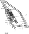
- FIG. 6 The drawing shows the holding device 12 in a representation from the right side and makes it clear that the holding device 12 has on both sides of its longitudinal center plane a receiving surface 23 for lamps 25 and a surface 24 for dissipating the heat emitted by the lamps 25 to the side walls 17.
- the lighting means 25 can be arranged on the surfaces 24, for example via receptacles carrying the lighting means in the form of, for example, circuit boards not shown in detail, and the arrangement of the circuit boards on the surfaces 24 results in the heat emitted by the light-emitting diodes 25 being emitted via the circuit boards to the receptacle surfaces 23, from where it is transferred to the side walls 17 via heat conduction and/or convection and/or radiation and is dissipated there by the intake air flowing through the air duct 15.
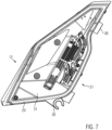
- the holding device 12 has a largely triangular configuration in a side view and has receptacles 26 which serve to arrange the holding device 12 on frame components 27 of the motorcycle 2, as shown in Fig. 13 shown in the drawing.
- the holding device 12 has on both side walls 17 on the outer area 28 spaced from the air duct 15, receiving surfaces 29 designed as circumferential grooves 30 for the arrangement of the Fig. 1 the drawing, which cover the respective receiving space 31 of the holding device 12 for the arrangement of the lamps 25 and close it off to the outside.
- the lamps 25 are protected against environmental influences in the form of, for example, rain and dirt and can emit light via the transparent cover plates 13.
- FIG. 8 The drawing shows a view of the holding device 12 from above.
- the air duct 15 between the side walls 17 is tapered from the air inlet area 20 toward the air outlet area 21. This configuration ensures that the intake air flowing through the air duct 15 experiences a flow acceleration on its path through the air duct 15, thus achieving a configuration that enhances the performance of the internal combustion engine 3 by improving the filling level of the combustion chambers of the internal combustion engine 3.
- FIG. 9 The drawing shows a modified embodiment of the air intake device 1, which differs from the one shown in Fig. 1 illustrated embodiment in that an air guide funnel 32 is provided between the holding device 12 and the air guide device 8, which has a funnel inlet area 33 which is complementary in shape and area to the air outlet area 21 the holding device 12 and has a widening funnel outlet area 34 which is designed to be complementary in shape and area to the inlet area 35.
- FIG. 10 The drawing shows that the air guide funnel 32, together with the holding device 12, can be pivoted around the steering head bearing tube 36 during a steering movement on the motorcycle 2. Due to its design, which complements the shape and surface area of the inlet region 35 of the air guide device 8, it can be pivoted without the formation of an increasing gap region between the inlet region 35 and the funnel outlet region 34, thus preventing a deterioration in the flow characteristics of the intake air provided by the air intake device 1 due to a steering movement on the motorcycle.
- the air guide funnel 32 can be formed from an elastomer, for example a rubber-like material, which conforms to the funnel inlet region 33 of the air guide funnel 32.
- FIG. 11 The drawing shows a top view of a motorcycle 2 equipped with the air intake device 1 according to the invention.
- FIG. 12 The drawing shows a top view of a known motorcycle originating from the applicant and equipped with the known air intake device.
- the known air intake device has air inlet areas, designated by reference numeral 37, in air guide channels 38, which extend around the steering head bearing tube 39 and are covered from the outside by fairing components 40.
- the reduction of the air resistance of the motorcycle 2 with the air intake device according to the invention ensures a more efficient configuration in terms of achievable fuel consumption and also ensures that the overall visual impression of the motorcycle is improved due to the slimmer configuration of the motorcycle 2 in the width direction.
- FIG. 13 The drawing shows a side view of a motorcycle 2 provided with the air intake device 1 according to the invention, the motorcycle having a front wheel 42, a rear wheel 43, a rider's saddle 44 and the already mentioned internal combustion engine 3.
- the intake air enters the air guide channel 45 - symbolically represented by the arrows 45 - and is guided from there via the air guide device 8 and the intake air lines 9 to the housing 7 of the air intake device 1 according to the invention.
- the holding device 12 with its air guide channel 15 is designed both to guide the intake air and to receive the air flow described in more detail with reference to Fig. 1
- the light source 25 shown in the drawing is designed in the form of light-emitting diodes and can dissipate heat emitted by the light-emitting diodes during operation via the intake air flowing through the air duct 15, so that a multifunctional configuration has been created with the air intake device according to the invention.
Landscapes
- Engineering & Computer Science (AREA)
- Mechanical Engineering (AREA)
- Chemical & Material Sciences (AREA)
- Combustion & Propulsion (AREA)
- General Engineering & Computer Science (AREA)
- Transportation (AREA)
- Cooling, Air Intake And Gas Exhaust, And Fuel Tank Arrangements In Propulsion Units (AREA)
- Automatic Cycles, And Cycles In General (AREA)
Description
- Die vorliegende Erfindung betrifft eine Luftansaugvorrichtung für ein mit einer Brennkraftmaschine ausgestattetes Fahrzeug, mit einer gereinigte Ansaugluft für die Verbrennung in Richtung zur Brennkraftmaschine führenden Einrichtung und einem Luftfilterelement sowie einem das Luftfilterelement aufnehmenden Gehäuse und mindestens einer Luftführungseinrichtung, welche kanalförmig ausgebildet ist und zur Führung von Ansaugluft zum Gehäuse vorgesehen ist und sich die Luftführungseinrichtung im Bereich zwischen einer Halteeinrichtung und dem Gehäuse erstreckt, nach dem Oberbegriff des Anspruchs 1.
- Anhand eines auf die Anmelderin zurückgehenden Motorrads ist eine gattungsgemäße Luftansaugvorrichtung bekannt geworden, wie sie vorstehend beschrieben wurde und bei der zwei Luftführungseinrichtungen in der Form von mit einem rechteckigen Querschnitt versehenen Kanälen vorgesehen sind, die in ein Gehäuse münden, in dem ein Luftfilterelement vorgesehen ist. Die gereinigte Luft wird dann mittels einer Einrichtung in der Form von zwei Luftführungen einer Drosselklappeneinrichtung und stromabwärts dieser der Brennkraftmaschine zugeführt.
- Diese vorstehend erwähnten Kanäle erstrecken sich dabei von einer stirnseitigen Vorderseite des Gehäuses ausgehend in Fahrtrichtung des Motorrads betrachtet in Richtung nach vorne und beiderseitig von einer Längsmittelebene des Gehäuses ausgehend nach außen, sodass sich die jeweilige Lufteintrittsöffnung des Kanals in einer Ansicht auf die bekannte Konfiguration von oben außerhalb der äußeren seitlichen Umrissbegrenzungslinien des Gehäuses befinden. Diese Konfiguration ist erforderlich, da sich die Kanäle mit ihren Lufteintrittsöffnungen um eine den Hauptscheinwerfer des Motorrads aufnehmende Lampenmaske herum erstrecken müssen, da die Lampenmaske, die mit ihrer flächigen seitlichen Erstreckung den Hauptscheinwerfer aufnimmt und umgibt, andernfalls den Eintritt von Frischluft oder Ansaugluft in die Lufteintrittsöffnungen der Kanäle behindert.
- Das genannte Fahrzeug besitzt seitlich eines Hauptrahmens des Motorrads angeordnete Seitenverkleidungselemente, welche die Kanäle seitlich abdecken, sodass sich die Lufteintrittsöffnungen innerhalb der Seitenverkleidungselemente befinden.
- Obwohl sich diese Konfiguration bereits bestens bewährt hat, besitzt sie dennoch Raum für Verbesserungen dahingehend, dass in Fahrzeuglängsrichtung die Baubreite der bekannten Luftansaugvorrichtung zu verringern ist und damit die Baubreite des Fahrzeugs insgesamt verringert werden kann, womit gleichzeitig die den Fahrwiderstand des Motorrads beeinflussende Stirnfläche verringert werden kann.
- Auch anhand der
JP 2011 173504 A - Ausgehend hiervon liegt der vorliegenden Erfindung die Aufgabe zugrunde, die bekannte Luftansaugvorrichtung derart weiterzubilden, dass sich eine Luftansaugvorrichtung mit quer zur Fahrzeuglängsrichtung betrachtet verringerter Baubreite einstellt und somit die Baubreite des Fahrzeugs insgesamt verringert werden kann. Auch soll ein mit der bereitzustellenden Luftansaugvorrichtung versehenes Fahrzeug bereitgestellt werden.
- Die Erfindung weist zur Lösung dieser Aufgabe hinsichtlich der Luftansaugvorrichtung die im Anspruch 1 angegebenen Merkmale auf. Vorteilhafte Ausgestaltungen hiervon sind in den weiteren Ansprüchen beschrieben. Darüber hinaus weist die Erfindung hinsichtlich des zu schaffenden Fahrzeugs die im Anspruch 11 angegebenen Merkmale auf.
- Die Erfindung schafft eine Luftansaugvorrichtung für ein mit einer Brennkraftmaschine ausgestattetes Fahrzeug, mit einer gereinigte Ansaugluft für die Verbrennung in Richtung zur Brennkraftmaschine führenden Einrichtung und einem Luftfilterelement sowie einem das Luftfilterelement aufnehmenden Luftfiltergehäuse und mindestens einer Luftführungseinrichtung, welche kanalförmig ausgebildet und zur Führung von Ansaugluft zum Luftfiltergehäuse vorgesehen ist und sich die Luftführungseinrichtung im Bereich zwischen einer Halteeinrichtung und dem Luftfiltergehäuse erstreckt, wobei die Halteeinrichtung beidseits einer in Fahrtrichtung vertikalen Längsmittelebene eine Seitenwand mit einer Aufnahmefläche besitzt, an der eine jeweilige Leiterplatte mit mindestens einem an der Leiterplatte angeordneten Leuchtmittel angeordnet ist, und die jeweilige Aufnahmefläche eine Fläche aufweist, welche zur Übertragung von vom Leuchtmittel abgegebener Wärme an die jeweilige Seitenwand eingerichtet ist, und die Halteeinrichtung einen zu den Leuchtmitteln benachbarten Luftleitkanal aufweist, der mit der Luftführungseinrichtung luftführend verbunden ist, wobei der Luftleitkanal zwischen den einander gegenüberliegenden Seitenwänden der Halteeinrichtung ausgebildet ist.
- Mit der erfindungsgemäßen Ausgestaltung der Luftansaugvorrichtung wird erreicht, dass durch die Integration des dem Leuchtmittel benachbarten Luftleitkanals in die Halteeinrichtung in der Form der Halteeinrichtung ein multifunktionales Bauteil bereitgestellt wird, welches sowohl zur Aufnahme mindestens eines Leuchtmittels ausgebildet ist als auch gleichzeitig die Funktion der Leitung oder Führung der Ansaugluft mittels des Luftleitkanals zur Luftführungseinrichtung ausführt.
- Die Halteeinrichtung wird in vorteilhafter Weise in Fahrzeuglängsrichtung beispielsweise mittig oder im Bereich der Längsmittelebene des Fahrzeugs angeordnet, sodass sich die Luftführungseinrichtung von der Halteeinrichtung ausgehend in Richtung zum Gehäuse der Luftansaugvorrichtung erstreckt.
- Die Halteeinrichtung wird in vorteilhafter Weise am Fahrzeug vorne angeordnet, d. h. in Fahrzeuglängsrichtung betrachtet oder Fahrtrichtung des Fahrzeugs bei einer Vorwärtsfahrt am oder in der Nähe des vorderen Endbereichs des Fahrzeugs, sodass bei einer Vorwärtsfahrt des Fahrzeugs die Ansaugluft über den Luftleitkanal der Halteeinrichtung in die Luftführungseinrichtung gelangt. Es findet also durch diese Konfiguration in Abhängigkeit von der Fahrgeschwindigkeit des Fahrzeugs eine Staudruckaufladung statt und zudem sorgt die Konfiguration, dass sich der Luftleitkanal benachbart zum Leuchtmittel angeordnet befindet, dafür, dass der den Luftleitkanal durchströmende Ansaugluftstrom die vom Leuchtmittel auf die Halteeinrichtung übertragene Wärme abführen kann. Die Halteeinrichtung wirkt also gleichzeitig als Kühlkörper oder Kühleinrichtung für das oder die Leuchtmittel.
- Bei dem oder den Leuchtmitteln kann es sich in vorteilhafter Weise um Leuchtdioden handeln, welche beispielsweise an einer Steuerplatine oder Schaltplatine angeordnet sind, die gleichzeitig der Aufnahme der Leuchtdiode oder der Leuchtdioden dient und die so in oder an der Halteeinrichtung angeordnet ist, dass die Abwärme der Leuchtdioden und der auf der Steuerplatine oder Schaltplatine angeordneten Steuerelektronik auf die Halteeinrichtung übertragen wird, welche von dem Luftleitkanal durchzogen oder durchsetzt ist, sodass die den Luftleitkanal durchströmende Ansaugluft gleichzeitig als Kühlluftstrom fungieren kann.
- Durch die Konfiguration, dass sich die Luftführungseinrichtung im Bereich zwischen der Halteeinrichtung und dem Gehäuse erstreckt, wird erreicht, dass sich die Luftführungseinrichtung vom Gehäuse der Luftansaugvorrichtung in Richtung nach vorne erstreckt und sich somit in Fahrtrichtung des Fahrzeugs betrachtet eng an der Längsmittelebene des Fahrzeugs anschmiegt und somit verglichen mit der bekannten Luftansaugvorrichtung eine deutliche Verringerung der Erstreckung der Luftansaugvorrichtung in Breitenrichtung des Fahrzeugs erreicht wird.
- Somit wird durch die erfindungsgemäße Luftansaugvorrichtung eine multifunktionale Einrichtung geschaffen, die der Luftzuführung für die Brennkraftmaschine dient, gleichzeitig die Breitenerstreckung des Fahrzeugs verringert und zudem als Kühlkörper oder Kühleinrichtung für das oder die Leuchtmittel des Fahrzeugs dient.
- Es ist nach einer Weiterbildung der Erfindung vorgesehen, dass die Luftführungseinrichtung mindestens zwei abschnittsweise weitgehend parallel verlaufende Luftführungskanäle aufweist, die an einem Endbereich einstückig miteinander verbunden ausgebildet sind.
- Diese Konfiguration sorgt dafür, dass die parallel verlaufenden Luftführungskanäle vom Gehäuse der Luftansaugvorrichtung ausgehend an der Längsmittelebene des Fahrzeugs eng anliegend vorgesehen sind und so der in die Luftführungskanäle eintretende Ansaugluftstrom mit hoher Strömungsgeschwindigkeit in Richtung zum Gehäuse der Luftansaugvorrichtung strömen kann und auf diese Weise Fluidreibungsverluste durch Wandanlagerungen des Luftstroms in den Luftführungskanälen verringert werden können.
- Es ist nach einer Weiterbildung der Erfindung vorgesehen, dass die Luftansaugvorrichtung einen jeweiligen Luftführungskanal besitzt, der mittels einer gekrümmt ausgebildeten Ansaugluftleitung mit einer Einlassöffnung des Gehäuses luftführend verbunden ist und ein jeweiliger Endbereich des Luftführungskanals mit einem zugeordneten Anschlussbereich der Ansaugluftleitung in der Form einer gesteckten Verbindung lösbar verbindbar ausgebildet ist.
- Diese Konfiguration führt dazu, dass der jeweilige Luftführungskanal vom Luftleitkanal der Halteeinrichtung ausgehend in Richtung des Gehäuses eine einem Schnorchel ähnliche Ansaugluftleitung besitzt, die zur einfachen Montage bei der Fertigung des mit der erfindungsgemäßen Luftansaugvorrichtung ausgestatteten Fahrzeugs ohne Werkzeugeinsatz mittels der Herbeiführung einer einfachen Steckverbindung zwischen der Ansaugluftleitung und dem Luftführungskanal hergestellt werden kann.
- Es hat sich als vorteilhaft erwiesen, wenn die Ansaugluftleitung vom Luftführungskanal ausgehend eine bereichsweise oder abschnittsweise nach unten gerichtete Konfiguration aufweist, da auf diese Weise in den Luftleitkanal der Halteeinrichtung bei einer Fahrt des Fahrzeugs im Regen in Richtung zur Ansaugluftleitung eintretendes Wasser über eine beispielsweise in der Ansaugluftleitung vorgesehene Ablaufbohrung abgeleitet werden kann, bevor es in das Gehäuse der Luftansaugvorrichtung eintritt.
- Es ist nach einer Weiterbildung der Erfindung vorgesehen, dass die Halteeinrichtung ein mit dem zwischen Seitenwänden angeordneten Luftleitkanal ausgebildeter Körper ist, der die Seitenwände verbindende und zusammen mit den Seitenwänden den Luftleitkanal einschließende erste und zweite Körperelemente aufweist und einen Lufteintrittsbereich sowie einen der Luftführungseinrichtung zugewandten Luftaustrittsbereich aufweist.
- Die Seitenwände können gleichzeitig als Kühlkörper für die Ableitung der von dem oder den Leuchtmitteln und deren Steuerelektronik abgegebener Wärme dienen und bilden zusammen mit den ersten und zweiten Körperelementen, welche die Seitenwände verbinden, einen den Luftleitkanal einschließenden Bereich aus, der im in Fahrtrichtung des Fahrzeugs vorderen Bereich der Halteeinrichtung einen Lufteintrittsbereich ausbildet und im in Fahrtrichtung des Fahrzeugs hinteren Bereich der Halteeinrichtung einen Luftaustrittsbereich aufweist, der der Luftführungseinrichtung zugewandt ist. Der Luftleitkanal der Halteeinrichtung kann im Bereich zwischen dem Lufteintrittsbereich und dem Luftaustrittsbereich beispielsweise auch eine sich verjüngende Konfiguration aufweisen, sodass die den Luftleitkanal durchströmende Ansaugluft eine Strömungsbeschleunigung erfährt.
- Es ist nach einer Weiterbildung der Erfindung auch vorgesehen, dass die Halteeinrichtung mindestens eine Aufnahmefläche zur Anordnung mindestens eines Leuchtmittels aufweist und die Aufnahmefläche zur Ableitung von Wärme des Leuchtmittels ausgebildet ist.
- Die Aufnahmefläche kann beispielsweise zur Anordnung der vorstehend erwähnten Steuerplatine oder Schaltplatine dienen, sodass die von den beispielsweise als Leuchtdioden ausgebildeten Leuchtmitteln abgegebene Wärme über die Aufnahmefläche an die Seitenwände der Halteeinrichtung abgegeben wird, welche an der dem Luftleitkanal zugewandten Seite von der durch den Luftleitkanal durchströmenden Ansaugluft aktiv gekühlt werden.
- Es ist nach einer Weiterbildung der Erfindung auch vorgesehen, dass die Halteeinrichtung an einem der Luftführungseinrichtung zugewandten Endbereich des Luftleitkanals eine zur Konfiguration eines Lufteintrittsbereichs der Luftführungseinrichtung weitgehend form- und flächenkomplementäre Konfiguration aufweist.
- Die Halteeinrichtung kann bei ihrer Anordnung an beispielsweise einem Motorrad im Bereich der oberen Gabelbrücken einer Vorderradgabel des Motorrads angeordnet sein, sodass die Halteeinrichtung bei Lenkbewegungen des Motorrads zusammen mit der Vorderradgabel relativ zur Längsmittelachse beziehungsweise Längsmittelebene des Motorrads Verschwenkbewegungen erfährt und sich so eine Winkelveränderung des Luftaustrittsbereichs des Luftleitkanals der Halteeinrichtung relativ zum Lufteintrittsbereich der Luftführungseinrichtung einstellt.
- Durch die form- und flächenkomplementäre Konfiguration des Endbereichs des Luftleitkanals relativ zum Lufteintrittsbereich der Luftführungseinrichtung wird erreicht, dass der den Luftleitkanal weitgehend laminar durchströmende Ansaugluftstrom im Übergangsbereich zwischen dem Luftleitkanal und dem Lufteintrittsbereich der Luftführungseinrichtung nur wenige, die laminare Strömung beeinträchtigende Fluidstörungen erfährt und sich somit eine hohe Strömungsgeschwindigkeit im gesamten Ansaugluftbereich vor dem Gehäuse der Luftansaugvorrichtung einstellt.
- Es ist nach einer Weiterbildung der Erfindung auch vorgesehen, dass die Halteeinrichtung an vom Luftführungskanal abgewandten Außenbereichen der Seitenwände Aufnahmeflächen zur Anordnung von Leuchtmittel überdeckenden Abdeckscheiben aufweist.
- Durch diese Konfiguration wird es erreicht, dass beidseits des Luftführungskanals, der die Halteeinrichtung vollständig durchsetzen kann, an den Seitenwänden Abdeckscheiben angeordnet werden können, welche so beidseits des Luftführungskanals angeordnet sind und jeweils einen Aufnahmeraum zwischen den Seitenwänden und den Abdeckscheiben begrenzen, in welchem das oder die Leuchtmittel angeordnet sein können.
- Auf diese Weise befindet sich beidseits des Luftführungskanals jeweils ein Aufnahmeraum angeordnet, in dem beispielsweise die Steuerplatine mit den daran angeordneten Leuchtdioden an der jeweiligen, vorstehend bereits erwähnten Aufnahmefläche angeordnet sind und der jeweilige Aufnahmeraum außen von der Abdeckscheiben überspannt wird. Der Luftführungskanal durchsetzt die Halteeinrichtung vollständig und befindet sich daher zwischen den Abdeckscheiben angeordnet und die durch den Luftführungskanal strömende Ansaugluft kühlt die dem Luftführungskanal jeweils zugeordnete Rückseite der jeweiligen Seitenwand. Durch die beidseits des Luftführungskanals vorgesehenen Aufnahmeräume für Leuchtmittel können eine dem jeweiligen Bedarf an Leuchtstärke der Leuchtmittel des Fahrzeugs angepasste Zahl an Leuchtmittel in der Form von beispielsweise Leuchtdioden integriert werden.
- Es ist nach einer Weiterbildung der Erfindung vorgesehen, dass Seitenwände der Halteeinrichtung in einer Seitenansicht eine einem Dreieck ähnliche Konfiguration aufweisen und obere Bereiche der Seitenwände mit dem ersten Körperelement einstückig ausgebildet sind und die Seitenwände im Abstand zu unteren Bereichen der Seitenwände mit dem zweiten Körperelement einstückig ausgebildet sind. Durch diese Konfiguration wird gleichsam ein einem Einlauftrichter ähnliche Konfiguration des Luftleitkanals der Halteeinrichtung ausgebildet, die für eine hohe Strömungsgeschwindigkeit der Ansaugluft im Bereich des Luftleitkanals der Halteeinrichtung sorgt.
- Es ist nach einer Weiterbildung der Erfindung vorgesehen, dass die Halteeinrichtung Mittel zur Anordnung von mindestens einer, mindestens ein Leuchtmittel tragender Aufnahme aufweist und das Mittel und/oder die Aufnahme und/oder das Leuchtmittel mit der Halteeinrichtung zur Wärmeübertragung auf die Halteeinrichtung funktional gekoppelt ist.
- Bei dem Mittel kann es sich beispielsweise um eine oder mehrere Gewindebohrungen handeln, an denen die ein Leuchtmittel tragende Aufnahme in der Form beispielsweise einer Leiterplatte festgelegt werden kann. Bei dem Mittel kann es sich beispielsweise auch um eine zur Aufnahme eines elastischen Bauteils in der Form beispielsweise eines aus einem Elastomer ausgebildeten Abstandhalters ausgebildeten Ausnehmung handeln, sodass mit dem oder den elastischen Abstandhaltern die Leiterplatte mit den daran angeordneten Leuchtdioden schwingungsbedämpft oder schwingungsentkoppelt an der Halteeinrichtung festgelegt werden kann. Diese Konfiguration sorgt dafür, dass beispielsweise von der Brennkraftmaschine des Fahrzeugs induzierte Schwingungen nicht oder nur gedämpft auf die Leuchtdioden übertragen werden.
- Es ist nach einer Weiterbildung der Erfindung auch vorgesehen, dass der Luftleitkanal der Halteeinrichtung mit einer Führungseinrichtung oder Führungsfläche zur Führung von den Luftleitkanal durchströmender Luft in Kontakt mit einer vom Wärme abgebenden Leuchtmittel erwärmten Fläche mindestens einer Seitenwand ausgebildet ist.
- Bei der Führungseinrichtung oder Führungsfläche kann es sich beispielsweise um eine in den Luftleitkanal integrierte Luftleitfläche handeln, welche die in den Luftleitkanal strömende Ansaugluft gezielt auf den Bereich der Seitenwand beziehungsweise der Seitenwände der Halteeinrichtung leitet, der über die Abwärme der Leuchtmittel am meisten erwärmt wird.
- Es ist nach einer Weiterbildung der Erfindung auch vorgesehen, dass der Endbereich der Luftführungseinrichtung einen sich in Richtung zum Lufteintrittsbereich querschnittlich erweiternden Übergangsbereich besitzt, welcher dem Luftleitkanal der Halteeinrichtung zugeordnet ist.
- Auf diese Weise wird erreicht, dass die aus dem Luftaustrittsbereich des Luftleitkanals der Halteeinrichtung ausströmende Ansaugluft auch bei einer Winkelveränderung der Halteeinrichtung relativ zur Luftführungseinrichtung, beispielsweise aufgrund der vorstehend bereits erwähnten Verschwenkbewegungen der Halteeinrichtung bei Lenkbewegungen am Fahrzeug, gezielt in den Lufteintrittsbereich der Luftführungseinrichtung tritt und nicht beispielsweise stumpf auf eine den Lufteintrittsbereich der Luftführungseinrichtung begrenzende Wandfläche. Diese Konfiguration sorgt dafür, dass eine hohe Geschwindigkeit der den Luftleitkanal durchsetzenden Ansaugluft auch bei Lenkbewegungen beibehalten bleibt.
- Die Erfindung schafft schließlich auch ein Fahrzeug mit mindestens einem Vorderrad sowie mindestens einem Hinterrad und einer Brennkraftmaschine, welche eine Luftansaugvorrichtung aufweist, wie sie vorstehend beschrieben wurde. Bei dem Fahrzeug kann es sich beispielsweise um eine einspuriges Fahrzeug in der Form eines Motorrads handeln, oder auch um ein mehr als einspuriges Fahrzeug in der Form eines All-Terrain Vehicles oder ATVs oder Quads.
- Die Erfindung wird im folgenden anhand der Zeichnung näher erläutert. Diese zeigt in:
-
Fig. 1 eine Ausführungsform der Luftansaugvorrichtung nach der Erfindung in einer Explosionsdarstellung; -
Fig. 2 eine weitere Explosionsdarstellung von Elementen der Luftansaugvorrichtung; -
Fig. 3 eine Ansicht von oben auf Elemente der Luftansaugvorrichtung; -
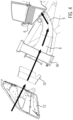
Fig. 4 eine schematische Darstellung zur Erläuterung der Führung der Ansaugluft in Richtung zum Gehäuse der Luftansaugvorrichtung; -
Fig. 5 eine perspektivische Darstellung einer Halteeinrichtung der Luftansaugvorrichtung; -
Fig. 6 eine Darstellung der Halteeinrichtung in einer rechten Seitenansicht; -
Fig. 7 eine Darstellung der Halteeinrichtung in einer linken Seitenansicht; -
Fig. 8 eine Ansicht von oben auf die Halteeinrichtung; -
Fig. 9 eine teilweise Explosionsdarstellung einer Luftansaugvorrichtung nach einer modifizierten Ausführungsform; -
Fig. 10 eine schematische Darstellung einer Ansicht von oben auf eine Luftansaugvorrichtung nach der modifizierten Ausführungsform in eine Drehwinkelstellung; -
Fig. 11 eine Ansicht von oben auf ein mit der erfindungsgemäßen Luftansaugvorrichtung ausgestattetes Motorrad; -
Fig. 12 zum Vergleich mit derFig. 11 eine Ansicht von oben auf ein mit der bekannten Luftansaugvorrichtung ausgestattetes Motorrad; und -
Fig. 13 eine Seitenansicht eines schematisch dargestellten Motorrads mit der erfindungsgemäßen Luftansaugvorrichtung. -
Fig. 1 der Zeichnung zeigt eine Explosionsdarstellung einer Ausführungsform einer Luftansaugvorrichtung 1 gemäß der vorliegenden Erfindung. - Die Luftansaugvorrichtung 1 ist beispielsweise zur Anordnung an dem in
Fig. 13 der Zeichnung dargestellten Motorrad 2 vorgesehen. Das Motorrad 2 besitzt eine Brennkraftmaschine 3, bei der es sich bei der dargestellten Ausführungsform des Motorrads um einen V2 Motor handelt. - Die Luftansaugvorrichtung 1 besitzt eine gereinigte Ansaugluft in Richtung zur Brennkraftmaschine führende Einrichtung, bei der es sich ganz allgemein um einen kanalförmigen Körper oder ein Luftführungsmittel handeln kann, und bei der es sich bei der dargestellten Ausführungsform um in
Fig. 2 der Zeichnung ersichtliche Trichter oder Luftführungstrichter 4 handelt, welche beispielsweise auch einen Teil eines Drosselklappenkörpers 5 darstellen können, und dafür vorgesehen sind, die über ein Luftfilterelement 6 gereinigte Ansaugluft in Richtung zu dem Einlassbereich der Brennkraftmaschine 3 für den Eintritt der Ansaugluft und/oder eines Ansaugluft-Kraftstoff-Gemisches in den Brennraum der jeweiligen Zylinder der Brennkraftmaschine 3 führen zu können. - Die Luftansaugvorrichtung 1 weist darüber hinaus ein das Luftfilterelement 6 aufnehmendes Gehäuse 7 auf, und besitzt eine kanalförmige ausgebildete Luftführungseinrichtung 8, welche in Ansaugluftleitungen 9 mündet, welche die noch ungereinigte Ansaugluft in Richtung zum Gehäuse 7 führen.
- Nachdem die noch ungereinigte Ansaugluft in das Gehäuse oder Luftfiltergehäuse 7 eingetreten ist, wird sie durch das Luftfilterelement 6 zur Reinigung der Ansaugluft hindurch geführt, und tritt dann über den Innenraum 10 des Gehäuses 7 in Richtung zu den Trichtern 4 weiter und wird dann mit Kraftstoff angereichert, um letztlich in die Brennräume der Brennkraftmaschine 3 zu gelangen.
- Wie es beispielsweise anhand von
Fig. 1 der Zeichnung ersichtlich ist, ist am Lufteintrittsbereich 11 der Luftführungseinrichtung 8 eine näher anhand derFiguren 5 bis 8 der Zeichnung dargestellte Halteeinrichtung 12 vorgesehen, welche sowohl der Führung der Ansaugluft in Richtung zur Luftführungseinrichtung 8 als auch der Aufnahme mindestens eines Leuchtmittels des Motorrads 2 dient und einen ganz allgemein mit dem Bezugszeichen 46 bezeichneten Körper aufweist. -
Fig. 1 der Zeichnung zeigt darüber hinaus der Erläuterung halber die Halteeinrichtung 12 auch noch mit Abdeckscheiben 13 versehen, welche dem Schutz und der Abdeckung der an der Halteeinrichtung 12 vorgesehenen Leuchtmittel dienen. - Die Leuchtmittel 25 sind bei der in der Zeichnung dargestellten Halteeinrichtung 12 zu beiden Seiten des Luftleitkanals 15 in den unter den Abdeckscheiben 13 vorgesehenen Innenräumen oder Bereichen angeordnet.
- Ein in
Fig. 1 der Zeichnung dargestellter Schlauch 14, der an der Ansaugluftleitung 9 angeordnet ist, dient der Ableitung von Kondensat oder Wasser, welches beispielsweise bei einer Fahrt des Motorrads 2 im Regen in die Luftführungseinrichtung 8 eintreten kann und abgeführt wird, bevor er ist in das Gehäuse 7 der Luftansaugvorrichtung 1 eintreten kann. Die zweite Ansaugluftleitung 9 weist ebenfalls einen Schlauch zur Ableitung von Wasser oder Kondensat auf. - Die Halteeinrichtung 12 ist mit einem näher anhand der weiteren Figuren ersichtlichen Luftleitkanal 15 versehen, in den die Ansaugluft am vorderen Bereich eintreten und am hinteren Bereich der Halteeinrichtung 12 in Richtung zum Lufteintrittsbereich der Luftführungseinrichtung 8 wieder austreten kann.
- Wie es anhand von
Fig. 3 der Zeichnung ersichtlich ist, weist die Luftführungseinrichtung 8 zwei abschnittsweise parallel verlaufende Luftführungskanäle 16 auf, welche am in der Zeichnung hinteren Bereich in die Ansaugluftleitungen 9 münden. Die Luftführungskanäle 16 besitzen dabei im Bereich der Ansaugluftleitungen 9 einen jeweiligen komplementär zum Einlassbereich der Ansaugluftleitungen 9 ausgebildeten Endbereich, sodass die Luftführungskanäle 16 mit den Ansaugluftleitungen 9 in der Form einer gesteckten Verbindung lösbar miteinander verbunden werden können, ohne dass hierzu Werkzeugeinsatz bei der Montage erforderlich ist. - Die Ansaugluftleitungen 9 sind dabei gekrümmt ausgebildet und münden in einer jeweiligen Einlassöffnung 47 des Gehäuses 7, wobei es aufgrund der Anordnung und Ausbildung der erfindungsgemäßen Luftansaugvorrichtung 1 über einen Lufteintritt am vorderen Bereich des Luftleitkanals 15, wie dies in
Fig. 4 der Zeichnung dargestellt ist, und der weiteren Führung der Luft über die Luftführungseinrichtung 8 und die Ansaugluftleitung 9 in Richtung zum Luftfilterelement 6 zu einer die Leistung der Brennkraftmaschine 3 fördernden Staudruckaufladung kommt. -
Fig. 5 der Zeichnung zeigt eine perspektivische Darstellung der multifunktionalen Halteeinrichtung 12 der erfindungsgemäßen Luftansaugvorrichtung 1. - Die Halteeinrichtung 12 weist zwei Seitenwände 17 auf, welche zwischen sich den Luftleitkanal 15 einschließen, der von den Seitenwänden 17 und einem ersten oder oberen Körperelement 18 sowie einem zweiten oder unteren Körperelement 19 des Körpers 46 ausgebildet ist und am vorderen oder stirnseitigen Bereich einen Lufteintrittsbereich 20 und am hinteren oder rückwärtigen Bereich, der dem Lufteintrittsbereich 22 der Luftführungseinrichtung 8 zugeordnet ist, einen Luftaustrittsbereich 21 aufweist.
- Der Luftleitkanal 15 dient so der Führung der Ansaugluft durch die Halteeinrichtung 12 hindurch bis in den Lufteintrittsbereich 22 der Luftführungseinrichtung 8. Die Halteeinrichtung 12 ist bei der dargestellten Ausführungsform der Luftansaugvorrichtung 1 aus einer Leichtmetalllegierung gebildet, beispielsweise einer Aluminiumlegierung, sodass die durch den Luftleitkanal 15 hindurch tretende Ansaugluft während ihres gesamten Wegs durch den Luftleitkanal 15 hindurch mit den Seitenwänden 17 der Halteeinrichtung 12 in Kontakt kommt und auf diesem Weg Wärme von den Seitenwänden 17 abführen kann, die an diese von den Leuchtmitteln 25 abgegeben wird.
-
Fig. 5 der Zeichnung zeigt eine Aufnahmefläche 23, welche zur Anordnung mindestens eines Leuchtmittels 25 ausgebildet ist und eine Fläche 24 aufweist, an der die von dem oder den Leuchtmitteln 25, welche inFig. 1 der Zeichnung schematisch dargestellt sind, abgegebene Wärme an die Halteeinrichtung 12 und hier insbesondere an die Seitenwände 17 übertragen werden, und die Wärme über die den Luftleitkanal 15 durchsetzende Ansaugluft abgeführt wird, sodass die Halteeinrichtung 12 einerseits der Luftführung der Ansaugluft dient und andererseits auch der Abführung von Wärme der Leuchtmittel 25, die als Leuchtdioden ausgebildet sein können und zudem einen Aufnahmekörper für die Anordnung der Leuchtmittel 25 ausbildet. -
Fig. 6 der Zeichnung zeigt die Halteeinrichtung 12 in einer Darstellung von der rechten Seite und macht deutlich, dass die Halteeinrichtung 12 beidseitig ihrer Längsmittelebene jeweils eine Aufnahmefläche 23 für Leuchtmittel 25 und eine Fläche 24 für die Abführung der von den Leuchtmitteln 25 abgegebenen Wärme an die Seitenwände 17 aufweist. - Die Leuchtmittel 25 können dabei an den Flächen 24 beispielsweise über die Leuchtmittel tragende Aufnahmen in der Form von beispielsweise nicht näher dargestellten Leiterplatten angeordnet sein, und die Anordnung der Leiterplatten an den Flächen 24 dazu führt, dass die von den Leuchtdioden 25 abgegebene Wärme über die Leiterplatten an die Aufnahmeflächen 23 abgegeben wird, die von dort über Wärmeleitung und/oder Konvektion und/oder Strahlung an die Seitenwände 17 übertragen wird und dort von der durch den Luftleitkanal 15 durchströmenden Ansaugluft abgeführt wird.
- Wie es beispielsweise anhand von
Fig. 7 der Zeichnung dargestellt ist, weist die Halteeinrichtung 12 in einer Seitenansicht eine weitgehend dreieckförmige Konfiguration auf und besitzt Aufnahmen 26, die der Anordnung der Halteeinrichtung 12 an Rahmenbauteilen 27 des Motorrads 2 dienen, wie dies inFig. 13 der Zeichnung dargestellt ist. - Die Halteeinrichtung 12 weist an beiden Seitenwänden 17 am vom Luftleitkanal 15 beabstandeten äußeren Bereich 28 als umlaufende Nuten 30 ausgebildete Aufnahmeflächen 29 für die Anordnung der in
Fig. 1 der Zeichnung dargestellten Abdeckscheiben 13 auf, die den jeweiligen Aufnahmeraum 31 der Halteeinrichtung 12 für die Anordnung der Leuchtmittel 25 überdecken und nach außen abschließen. - Auf diese Weise sind die Leuchtmittel 25 gegen Umwelteinflüsse in der Form von beispielsweise Regen und Schmutz geschützt und können über die transparent ausgebildeten Abdeckscheiben 13 Licht abstrahlen.
-
Fig. 8 der Zeichnung zeigt eine Ansicht auf die Halteeinrichtung 12 von oben. Wie es ohne weiteres ersichtlich ist, ist der Luftleitkanal 15 zwischen den Seitenwänden 17 vom Lufteintrittsbereich 20 aus betrachtet in Richtung zum Luftaustrittsbereich 21 sich verjüngend ausgebildet. Diese Konfiguration sorgt dafür, dass die durch den Luftleitkanal 15 strömende Ansaugluft auf ihrem Weg durch den Luftleitkanal 15 hindurch eine Strömungsbeschleunigung erfährt und somit eine die Leistung der Brennkraftmaschine 3 fördernde Konfiguration über die damit erreichte Verbesserung des Füllungsgrads der Brennräume der Brennkraftmaschine 3 erreicht wird. -
Fig. 9 der Zeichnung zeigt eine modifizierte Ausführungsform der Luftansaugvorrichtung 1, die sich von der inFig. 1 dargestellten Ausführungsform dadurch unterscheidet, dass zwischen der Halteeinrichtung 12 und der Luftführungseinrichtung 8 ein Luftführungstrichter 32 vorgesehen ist, der einen Trichtereinlaufbereich 33 aufweist, der form- und flächenkomplementär zu dem Luftaustrittsbereich 21 der Halteeinrichtung 12 ausgebildet ist und einen sich erweiternden Trichterauslaufbereich 34 besitzt, der form- und flächenkomplementär zu dem Einlassbereich 35 ausgebildet ist. -
Fig. 10 der Zeichnung zeigt, dass der Luftführungstrichter 32 zusammen mit der Halteeinrichtung 12 bei einer Lenkbewegung am Motorrad 2 um das Lenkkopflagerrohr 36 herum verschwenkt werden kann und aufgrund seiner zum Einlassbereich 35 der Luftführungseinrichtung 8 form- und flächenkomplementären Ausbildung ohne die Ausbildung eines sich vergrößernden Spaltbereichs zwischen dem Einlassbereich 35 und dem Trichterauslassbereich 34 verschwenkt werden kann und somit eine Verschlechterung der Strömungscharakteristik der durch die Luftansaugvorrichtung 1 bereitgestellten Ansaugluft aufgrund einer Lenkbewegung am Motorrad vermieden werden kann. Der Luftführungstrichter 32 kann aus einem Elastomer gebildet sein, beispielsweise einem gummiartigen Werkstoff, der sich an den Trichtereinlaufbereich 33 des Luftführungstrichters 32 anschmiegt. -
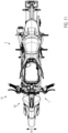
Fig. 11 der Zeichnung zeigt eine Ansicht von oben auf ein mit der erfindungsgemäßen Luftansaugvorrichtung 1 ausgestattetes Motorrad 2. - Im Vergleich hierzu zeigt
Fig. 12 der Zeichnung ein auf die Anmelderin zurückgehendes und mit der bekannten Luftansaugvorrichtung ausgestattetes bekanntes Motorrad in einer Ansicht von oben. Die bekannte Luftansaugvorrichtung weist mit dem Bezugszeichen 37 versehene Lufteinlassbereiche in Luftführungskanäle 38 auf, welche um das Lenkkopflagerohr 39 herum verlaufen und von außen von Verkleidungsbauteilen 40 abgedeckt sind. - Wird nun dieser Stirnflächenbereich 41 des bekannten Motorrads nach
Fig. 12 der Zeichnung mit dem Stirnflächenbereich 41 des Motorrads 2 mit der Luftansaugvorrichtung 1 nach der Erfindung verglichen, so wird sofort klar, dass die Stirnfläche 42 des bekannten Motorrads aufgrund der deutlich größeren Breitenerstreckung der Stirnfläche 42 des bekannten Motorrads in Richtung des Doppelpfeils B im direkten Vergleich mit der Stirnfläche 42 des Motorrads nachFig. 11 der Zeichnung wesentlich größer ist und daher auch der Luftwiderstand größer ist. - Die Verringerung des Luftwiderstands des Motorrads 2 mit der erfindungsgemäßen Luftansaugvorrichtung sorgt für eine hinsichtlich des erreichbaren Kraftstoffverbrauchs effizientere Konfiguration und sorgt außerdem dafür dass der optische Gesamteindruck des Motorrads aufgrund der in Breitenrichtung schlankeren Konfiguration des Motorrads 2 verbessert wird.
-
Fig. 13 der Zeichnung zeigt ein mit der erfindungsgemäßen Luftansaugvorrichtung 1 versehenes Motorrad 2 in einer Seitenansicht, wobei das Motorrad ein Vorderrad 42, ein Hinterrad 43, einen Fahrersattel 44 und die bereits erwähnte Brennkraftmaschine 3 aufweist. - Wie es ohne weiteres anhand von
Fig. 13 der Zeichnung ersichtlich ist, tritt - mit den Pfeilen 45 symbolisch dargestellt - die Ansaugluft in den Luftleitkanal 45 ein und wird von dort über die Luftführungseinrichtung 8 und die Ansaugluftleitungen 9 zum Gehäuse 7 der erfindungsgemäßen Luftansaugvorrichtung 1 geführt. Die Halteeinrichtung 12 ist mit ihrem Luftleitkanal 15 sowohl zur Führung der Ansaugluft ausgebildet als auch zur Aufnahme der näher anhand vonFig. 1 der Zeichnung ersichtlichen Leuchtmittel 25 in der Form von Leuchtdioden ausgebildet und kann von den Leuchtdioden im Betrieb abgegebene Wärme über die den Luftleitkanal 15 durchströmende Ansaugluft abführen, sodass mit der erfindungsgemäßen Luftansaugvorrichtung eine multifunktionale Konfiguration geschaffen wurde. - Hinsichtlich vorstehend im Einzelnen nicht näher erläuterter Merkmale der Erfindung wird in übrigen ausdrücklich auf die Patentansprüche und die Zeichnung verwiesen.
-
- 1.
- Luftansaugvorrichtung
- 2.
- Motorrad
- 3.
- Brennkraftmaschine
- 4.
- Trichter
- 5.
- Drosselklappenkörper
- 6.
- Luftfilterelement
- 7.
- Gehäuse
- 8.
- Luftführungseinrichtung
- 9.
- Ansaugluftleitung
- 10.
- Innenraum
- 11.
- Lufteintrittsbereich
- 12.
- Halteeinrichtung
- 13.
- Abdeckscheibe
- 14.
- Schlauch
- 15.
- Luftleitkanal
- 16.
- Luftführungskanäle
- 17.
- Seitenwand
- 18.
- Erstes Körperelement
- 19.
- Zweites Körperelement
- 20.
- Lufteintrittsbereich
- 21.
- Luftaustrittsbereich
- 22.
- Lufteintrittsbereich
- 23.
- Aufnahmefläche
- 24.
- Fläche
- 25.
- Leuchtmittel
- 26.
- Aufnahme
- 27.
- Rahmen
- 28.
- Bereich
- 29.
- Aufnahmefläche
- 30.
- Nut
- 31.
- Aufnahmeraum
- 32.
- Luftführungstrichter
- 33.
- Trichtereinlaufbereich
- 34.
- Trichterauslaufbereich
- 35.
- Einlassbereich
- 36.
- Lenkkopflagerohr
- 37.
- Lufteinlassbereich
- 38.
- Luftführungskanal
- 39.
- Lenkkopflagerohr
- 40.
- Verkleidungsbauteile
- 41.
- Stirnflächenbereich
- 42.
- Vorderrad
- 43.
- Hinterrad
- 44.
- Fahrersattel
- 45.
- Pfeile
- 46.
- Körper
- 47.
- Einlassöffnung
- B:
- Breitenerstreckung
Claims (11)
- Luftansaugvorrichtung (1) für ein mit einer Brennkraftmaschine (3) ausgestattetes Fahrzeug (2), mit einer gereinigte Ansaugluft für die Verbrennung in Richtung zur Brennkraftmaschine (3) führenden Einrichtung (4) und einem Luftfilterelement (6) sowie einem das Luftfilterelement (6) aufnehmenden Luftfiltergehäuse (7) und mindestens einer Luftführungseinrichtung (8), welche kanalförmig ausgebildet und zur Führung von Ansaugluft zum Luftfiltergehäuse (7) vorgesehen ist und sich die Luftführungseinrichtung (8) im Bereich zwischen einer Halteeinrichtung (12) und dem Luftfiltergehäuse (7) erstreckt, dadurch gekennzeichnet, dass die Halteeinrichtung (12) beidseits einer in Fahrtrichtung vertikalen Längsmittelebene eine Seitenwand (17) mit einer Aufnahmefläche (23) besitzt, an der eine jeweilige Leiterplatte mit mindestens einem an der Leiterplatte angeordneten Leuchtmittel (25) angeordnet ist, und die jeweilige Aufnahmefläche (23) eine Fläche (24) aufweist, welche zur Übertragung von vom Leuchtmittel (25) abgegebener Wärme an die jeweilige Seitenwand (17) eingerichtet ist, und die Halteeinrichtung (12) einen zu den Leuchtmitteln (25) benachbarten Luftleitkanal (15) aufweist, der mit der Luftführungseinrichtung (8) luftführend verbunden ist, wobei der Luftleitkanal (15) zwischen den einander gegenüberliegenden Seitenwänden (17) der Halteeinrichtung (12) ausgebildet ist.
- Luftansaugvorrichtung (1) nach Anspruch 1, dadurch gekennzeichnet, dass die Luftführungseinrichtung (8) mindestens zwei abschnittsweise parallel verlaufende Luftführungskanäle (16) aufweist, die an einem stromaufwärts gelegenen Endbereich einstückig miteinander verbunden ausgebildet sind.
- Luftansaugvorrichtung nach Anspruch 1 oder 2, gekennzeichnet durch einen jeweiligen Luftführungskanal (16), der mittels einer gekrümmt ausgebildeten Ansaugluftleitung (9) mit einer Einlassöffnung des Luftfiltergehäuses (7) luftführend verbunden ist und ein jeweiliger stromabwärts gelegener Endbereich des Luftführungskanals (16) mit einem zugeordneten Anschlußbereich der Ansaugluftleitung (9) in der Form einer gesteckten Verbindung lösbar verbindbar ausgebildet ist.
- Luftansaugvorrichtung (1) nach einem der vorstehenden Ansprüche, dadurch gekennzeichnet, dass die Halteeinrichtung (12) ein mit dem zwischen den Seitenwänden (17) angeordneten Luftleitkanal (15) ausgebildeter Körper (46) ist, der die Seitenwände (17) verbindende und zusammen mit den Seitenwänden (17) den Luftleitkanal (15) einschließende erste (18) und zweite (19) Körperelemente aufweist und einen Lufteintrittsbereich (21) sowie einen der Luftführungseinrichtung (8) zugewandten Luftaustrittsbereich (22) aufweist.
- Luftansaugvorrichtung (1) nach einem der vorstehenden Ansprüche, dadurch gekennzeichnet, dass die Halteeinrichtung (12) an einem der Luftführungseinrichtung (8) zugewandten Endbereich des Luftleitkanals (15) eine zur Konfiguration eines Lufteintrittsbereichs (22) der Luftführungseinrichtung (8) form- und flächenkomplementäre Konfiguration aufweist.
- Luftansaugvorrichtung (1) nach einem der Ansprüche 2 bis 5, dadurch gekennzeichnet, dass die Halteeinrichtung (12) an vom Luftführungskanal (16) abgewandten Außenbereichen der Seitenwände (17) Aufnahmeflächen (29) zur Anordnung von die Leuchtmittel (25) überdeckenden Abdeckscheiben (13) aufweist.
- Luftansaugvorrichtung (1) nach einem der vorstehenden Ansprüche, dadurch gekennzeichnet, dass die Seitenwände (17) der Halteeinrichtung (12) in einer Seitenansicht zur Fahrtichtung eine dreieckförmige Konfiguration aufweisen und obere Bereiche der Seitenwände (17) bezüglich einer Hochachse des Fahrzeugs mit dem ersten Körperelement (18) einstückig ausgebildet sind und die Seitenwände (17) im Abstand zu unteren Bereichen der Seitenwände (17) mit dem zweiten Körperelement (19) einstückig ausgebildet sind.
- Luftansaugvorrichtung nach Anspruch 7, dadurch gekennzeichnet, dass der Luftleitkanal (15) zwischen den Seitenwänden (17) und den einstückig ausgebildeten Bereichen der Halteeinrichtung (12) ausgebildet ist.
- Luftansaugvorrichtung (1) nach einem der vorstehenden Ansprüche, dadurch gekennzeichnet, dass die Halteeinrichtung (12) zu einer Hochachse des Fahrzeugs (2) verschwenkbar in einem Luftanströmbereich des Fahrzeugs (2) angeordnet ist.
- Luftansaugvorrichtung (1) nach einem der Ansprüche 2 bis 9, dadurch gekennzeichnet, dass der stromaufwärts gelegene Endbereich der Luftführungseinrichtung (8) einen sich in Richtung zum Lufteintrittsbereich (22) querschnittlich erweiternden Übergangsbereich besitzt, welcher dem Luftleitkanal (15) der Halteeinrichtung (12) zugeordnet ist.
- Fahrzeug (2) mit mindestens einem Vorderrad (42) sowie mindestens einem Hinterrad (43) und einer Brennkraftmaschine (2), gekennzeichnet durch eine Luftansaugvorrichtung (1) nach einem der vorstehenden Ansprüche.
Applications Claiming Priority (1)
| Application Number | Priority Date | Filing Date | Title |
|---|---|---|---|
| DE102018111179.7A DE102018111179B3 (de) | 2018-05-09 | 2018-05-09 | Luftansaugvorrichtung für ein mit einer Brennkraftmaschine ausgestattetes Fahrzeug |
Publications (2)
| Publication Number | Publication Date |
|---|---|
| EP3567309A1 EP3567309A1 (de) | 2019-11-13 |
| EP3567309B1 true EP3567309B1 (de) | 2025-05-21 |
Family
ID=66178870
Family Applications (1)
| Application Number | Title | Priority Date | Filing Date |
|---|---|---|---|
| EP19172090.3A Active EP3567309B1 (de) | 2018-05-09 | 2019-05-01 | Luftansaugvorrichtung für ein mit einer brennkraftmaschine ausgestattetes fahrzeug |
Country Status (5)
| Country | Link |
|---|---|
| US (1) | US11193458B2 (de) |
| EP (1) | EP3567309B1 (de) |
| JP (1) | JP7007325B2 (de) |
| DE (1) | DE102018111179B3 (de) |
| ES (1) | ES3036703T3 (de) |
Families Citing this family (3)
| Publication number | Priority date | Publication date | Assignee | Title |
|---|---|---|---|---|
| GB2613989B (en) * | 2019-05-15 | 2023-12-06 | Quantum Base Ltd | Alternative approach to the generation of a unique response to a challenge |
| EP4263334A1 (de) * | 2020-12-15 | 2023-10-25 | TVS Motor Company Limited | Grätschsitz-kraftfahrzeug |
| JP2026062088A (ja) * | 2024-09-30 | 2026-04-09 | 本田技研工業株式会社 | 鞍乗型車両 |
Family Cites Families (17)
| Publication number | Priority date | Publication date | Assignee | Title |
|---|---|---|---|---|
| JPS6338151Y2 (de) * | 1981-02-21 | 1988-10-07 | ||
| JPS5870418U (ja) * | 1981-11-05 | 1983-05-13 | 本田技研工業株式会社 | 自動二輪車のエンジン冷却風導入装置 |
| JP2523681Y2 (ja) * | 1988-03-23 | 1997-01-29 | スズキ株式会社 | 自動二輪車の導風装置 |
| JP3724879B2 (ja) * | 1996-07-29 | 2005-12-07 | ヤマハ発動機株式会社 | 自動二輪車 |
| JPH11208554A (ja) * | 1998-01-30 | 1999-08-03 | Yamaha Motor Co Ltd | 自動二輪車 |
| EP1382834A1 (de) * | 2002-07-16 | 2004-01-21 | Ducati Motor Holding S.p.A. | Lufteintrittsystem für ein Motorrad |
| JP3723792B2 (ja) * | 2002-09-13 | 2005-12-07 | 川崎重工業株式会社 | 車両用エンジンの空気取入装置 |
| US7329033B2 (en) * | 2005-10-25 | 2008-02-12 | Visteon Global Technologies, Inc. | Convectively cooled headlamp assembly |
| US7427152B2 (en) * | 2005-12-05 | 2008-09-23 | Visteon Global Technologies, Inc. | Headlamp assembly with integrated housing and heat sink |
| JP2008123756A (ja) * | 2006-11-09 | 2008-05-29 | Stanley Electric Co Ltd | 車両用灯具 |
| US8162101B2 (en) * | 2008-09-19 | 2012-04-24 | Kawasaki Jukogyo Kabushiki Kaisha | Ram intake unit having a sound absorbing structure |
| JP2011173504A (ja) * | 2010-02-24 | 2011-09-08 | Suzuki Motor Corp | 車両のヘッドライト装置 |
| JP5551979B2 (ja) * | 2010-06-28 | 2014-07-16 | 川崎重工業株式会社 | 乗物のランプ配置構造 |
| JP5965270B2 (ja) | 2012-09-28 | 2016-08-03 | 本田技研工業株式会社 | 自動二輪車における前部導風構造 |
| EP3277563B1 (de) * | 2015-04-03 | 2020-09-16 | Honda Motor Co., Ltd. | Aufbau einer beleuchtungsvorrichtung mit hilfsbeleuchtung |
| JP6447383B2 (ja) | 2015-06-17 | 2019-01-09 | スズキ株式会社 | 鞍乗型車両の吸気構造 |
| JP6120914B2 (ja) * | 2015-07-15 | 2017-04-26 | 本田技研工業株式会社 | 車両のカウルステー構造 |
-
2018
- 2018-05-09 DE DE102018111179.7A patent/DE102018111179B3/de active Active
-
2019
- 2019-05-01 ES ES19172090T patent/ES3036703T3/es active Active
- 2019-05-01 EP EP19172090.3A patent/EP3567309B1/de active Active
- 2019-05-02 JP JP2019087174A patent/JP7007325B2/ja active Active
- 2019-05-08 US US16/406,744 patent/US11193458B2/en active Active
Also Published As
| Publication number | Publication date |
|---|---|
| JP2019202758A (ja) | 2019-11-28 |
| JP7007325B2 (ja) | 2022-01-24 |
| EP3567309A1 (de) | 2019-11-13 |
| US20190345904A1 (en) | 2019-11-14 |
| US11193458B2 (en) | 2021-12-07 |
| ES3036703T3 (en) | 2025-09-23 |
| DE102018111179B3 (de) | 2019-05-09 |
Similar Documents
| Publication | Publication Date | Title |
|---|---|---|
| DE19703273B4 (de) | Kühler-Lüfter-Anordnung für ein Kraftrad | |
| DE60012440T2 (de) | Windlaufkonstruktion für ein Motorrad | |
| DE102007013309B4 (de) | Fahrzeugleuchte | |
| DE102017129199B4 (de) | Luftstrommanagementsystem für ein Fahrzeug | |
| DE10227735A1 (de) | Luftführungssystem für ein Motorrad | |
| DE19703274B4 (de) | Kühler-Ölkühler-Anordnung für ein Kraftrad | |
| DE102013208969A1 (de) | Vordere Luftführungsandordnung eines Motorrads | |
| DE102020103297B4 (de) | Beleuchtungsvorrichtung | |
| DE102013211357A1 (de) | Vorderteil-Luftführungsaufbau für ein Motorrad | |
| DE102017121735A1 (de) | Luftleitstruktur für satteltyp-fahrzeug | |
| DE102018111179B3 (de) | Luftansaugvorrichtung für ein mit einer Brennkraftmaschine ausgestattetes Fahrzeug | |
| DE19943138B4 (de) | Kraftstofftank an einem Zweirad-Kraftfahrzeug | |
| DE102014116817A1 (de) | Einlasskanalvorrichtung für ein Motorrad | |
| DE10337869A1 (de) | Kühlereinrichtung für ein Fahrzeug, insbesondere für eine Brennkraftmaschine eines Kraftfahrzeuges | |
| DE10348881B4 (de) | Luftschadstoffbehandlungsstruktur | |
| DE102019125199B4 (de) | Frontstruktur eines fahrzeugs | |
| DE102008064519A1 (de) | Personenkraftwagen mit einer Kanalanordnung zum Zuführen von Rohluft zu einem Luftfilter | |
| DE102022106756B4 (de) | Sattelsitzfahrzeug | |
| DE112018005491B4 (de) | Aussenabdeckungskomponentenstruktur für sattelfahrzeuge | |
| DE102014109035B4 (de) | Brennstoffzuführung für einen Verbrennungsmotor | |
| EP0890810A2 (de) | Kraftfahrzeug mit Unterbodenwärmetauscher | |
| DE3905254A1 (de) | Kuehlvorrichtung fuer kraftstoff-einspritzventile einer brennkraftmaschine | |
| DE102014211596B4 (de) | Kühlstruktur für Beleuchtungsvorrichtung für Grätschsitzfahrzeug | |
| DE102016124222A1 (de) | Fahrzeug des fahrsatteltyps | |
| EP3974755A2 (de) | Kühlerbaugruppe für ein fahrzeug |
Legal Events
| Date | Code | Title | Description |
|---|---|---|---|
| PUAI | Public reference made under article 153(3) epc to a published international application that has entered the european phase |
Free format text: ORIGINAL CODE: 0009012 |
|
| STAA | Information on the status of an ep patent application or granted ep patent |
Free format text: STATUS: THE APPLICATION HAS BEEN PUBLISHED |
|
| AK | Designated contracting states |
Kind code of ref document: A1 Designated state(s): AL AT BE BG CH CY CZ DE DK EE ES FI FR GB GR HR HU IE IS IT LI LT LU LV MC MK MT NL NO PL PT RO RS SE SI SK SM TR |
|
| AX | Request for extension of the european patent |
Extension state: BA ME |
|
| STAA | Information on the status of an ep patent application or granted ep patent |
Free format text: STATUS: REQUEST FOR EXAMINATION WAS MADE |
|
| 17P | Request for examination filed |
Effective date: 20200320 |
|
| RBV | Designated contracting states (corrected) |
Designated state(s): AL AT BE BG CH CY CZ DE DK EE ES FI FR GB GR HR HU IE IS IT LI LT LU LV MC MK MT NL NO PL PT RO RS SE SI SK SM TR |
|
| STAA | Information on the status of an ep patent application or granted ep patent |
Free format text: STATUS: EXAMINATION IS IN PROGRESS |
|
| 17Q | First examination report despatched |
Effective date: 20200528 |
|
| P01 | Opt-out of the competence of the unified patent court (upc) registered |
Effective date: 20230514 |
|
| GRAP | Despatch of communication of intention to grant a patent |
Free format text: ORIGINAL CODE: EPIDOSNIGR1 |
|
| STAA | Information on the status of an ep patent application or granted ep patent |
Free format text: STATUS: GRANT OF PATENT IS INTENDED |
|
| INTG | Intention to grant announced |
Effective date: 20240905 |
|
| GRAS | Grant fee paid |
Free format text: ORIGINAL CODE: EPIDOSNIGR3 |
|
| GRAA | (expected) grant |
Free format text: ORIGINAL CODE: 0009210 |
|
| STAA | Information on the status of an ep patent application or granted ep patent |
Free format text: STATUS: THE PATENT HAS BEEN GRANTED |
|
| AK | Designated contracting states |
Kind code of ref document: B1 Designated state(s): AL AT BE BG CH CY CZ DE DK EE ES FI FR GB GR HR HU IE IS IT LI LT LU LV MC MK MT NL NO PL PT RO RS SE SI SK SM TR |
|
| REG | Reference to a national code |
Ref country code: GB Ref legal event code: FG4D Free format text: NOT ENGLISH |
|
| REG | Reference to a national code |
Ref country code: CH Ref legal event code: EP |
|
| REG | Reference to a national code |
Ref country code: DE Ref legal event code: R096 Ref document number: 502019013362 Country of ref document: DE |
|
| REG | Reference to a national code |
Ref country code: IE Ref legal event code: FG4D Free format text: LANGUAGE OF EP DOCUMENT: GERMAN |
|
| REG | Reference to a national code |
Ref country code: ES Ref legal event code: FG2A Ref document number: 3036703 Country of ref document: ES Kind code of ref document: T3 Effective date: 20250923 |
|
| REG | Reference to a national code |
Ref country code: NL Ref legal event code: MP Effective date: 20250521 |
|
| PG25 | Lapsed in a contracting state [announced via postgrant information from national office to epo] |
Ref country code: PT Free format text: LAPSE BECAUSE OF FAILURE TO SUBMIT A TRANSLATION OF THE DESCRIPTION OR TO PAY THE FEE WITHIN THE PRESCRIBED TIME-LIMIT Effective date: 20250922 Ref country code: FI Free format text: LAPSE BECAUSE OF FAILURE TO SUBMIT A TRANSLATION OF THE DESCRIPTION OR TO PAY THE FEE WITHIN THE PRESCRIBED TIME-LIMIT Effective date: 20250521 |
|
| REG | Reference to a national code |
Ref country code: LT Ref legal event code: MG9D |
|
| PG25 | Lapsed in a contracting state [announced via postgrant information from national office to epo] |
Ref country code: GR Free format text: LAPSE BECAUSE OF FAILURE TO SUBMIT A TRANSLATION OF THE DESCRIPTION OR TO PAY THE FEE WITHIN THE PRESCRIBED TIME-LIMIT Effective date: 20250822 Ref country code: NO Free format text: LAPSE BECAUSE OF FAILURE TO SUBMIT A TRANSLATION OF THE DESCRIPTION OR TO PAY THE FEE WITHIN THE PRESCRIBED TIME-LIMIT Effective date: 20250821 |
|
| PG25 | Lapsed in a contracting state [announced via postgrant information from national office to epo] |
Ref country code: PL Free format text: LAPSE BECAUSE OF FAILURE TO SUBMIT A TRANSLATION OF THE DESCRIPTION OR TO PAY THE FEE WITHIN THE PRESCRIBED TIME-LIMIT Effective date: 20250521 Ref country code: NL Free format text: LAPSE BECAUSE OF FAILURE TO SUBMIT A TRANSLATION OF THE DESCRIPTION OR TO PAY THE FEE WITHIN THE PRESCRIBED TIME-LIMIT Effective date: 20250521 |
|
| PG25 | Lapsed in a contracting state [announced via postgrant information from national office to epo] |
Ref country code: BG Free format text: LAPSE BECAUSE OF FAILURE TO SUBMIT A TRANSLATION OF THE DESCRIPTION OR TO PAY THE FEE WITHIN THE PRESCRIBED TIME-LIMIT Effective date: 20250521 |
|
| PG25 | Lapsed in a contracting state [announced via postgrant information from national office to epo] |
Ref country code: HR Free format text: LAPSE BECAUSE OF FAILURE TO SUBMIT A TRANSLATION OF THE DESCRIPTION OR TO PAY THE FEE WITHIN THE PRESCRIBED TIME-LIMIT Effective date: 20250521 |
|
| PG25 | Lapsed in a contracting state [announced via postgrant information from national office to epo] |
Ref country code: RS Free format text: LAPSE BECAUSE OF FAILURE TO SUBMIT A TRANSLATION OF THE DESCRIPTION OR TO PAY THE FEE WITHIN THE PRESCRIBED TIME-LIMIT Effective date: 20250821 |
|
| PG25 | Lapsed in a contracting state [announced via postgrant information from national office to epo] |
Ref country code: IS Free format text: LAPSE BECAUSE OF FAILURE TO SUBMIT A TRANSLATION OF THE DESCRIPTION OR TO PAY THE FEE WITHIN THE PRESCRIBED TIME-LIMIT Effective date: 20250921 |
|
| PG25 | Lapsed in a contracting state [announced via postgrant information from national office to epo] |
Ref country code: LV Free format text: LAPSE BECAUSE OF FAILURE TO SUBMIT A TRANSLATION OF THE DESCRIPTION OR TO PAY THE FEE WITHIN THE PRESCRIBED TIME-LIMIT Effective date: 20250521 |
|
| PG25 | Lapsed in a contracting state [announced via postgrant information from national office to epo] |
Ref country code: DK Free format text: LAPSE BECAUSE OF FAILURE TO SUBMIT A TRANSLATION OF THE DESCRIPTION OR TO PAY THE FEE WITHIN THE PRESCRIBED TIME-LIMIT Effective date: 20250521 Ref country code: SM Free format text: LAPSE BECAUSE OF FAILURE TO SUBMIT A TRANSLATION OF THE DESCRIPTION OR TO PAY THE FEE WITHIN THE PRESCRIBED TIME-LIMIT Effective date: 20250521 |
|
| PG25 | Lapsed in a contracting state [announced via postgrant information from national office to epo] |
Ref country code: CZ Free format text: LAPSE BECAUSE OF FAILURE TO SUBMIT A TRANSLATION OF THE DESCRIPTION OR TO PAY THE FEE WITHIN THE PRESCRIBED TIME-LIMIT Effective date: 20250521 |
|
| PG25 | Lapsed in a contracting state [announced via postgrant information from national office to epo] |
Ref country code: EE Free format text: LAPSE BECAUSE OF FAILURE TO SUBMIT A TRANSLATION OF THE DESCRIPTION OR TO PAY THE FEE WITHIN THE PRESCRIBED TIME-LIMIT Effective date: 20250521 |
|
| PG25 | Lapsed in a contracting state [announced via postgrant information from national office to epo] |
Ref country code: SK Free format text: LAPSE BECAUSE OF FAILURE TO SUBMIT A TRANSLATION OF THE DESCRIPTION OR TO PAY THE FEE WITHIN THE PRESCRIBED TIME-LIMIT Effective date: 20250521 Ref country code: RO Free format text: LAPSE BECAUSE OF FAILURE TO SUBMIT A TRANSLATION OF THE DESCRIPTION OR TO PAY THE FEE WITHIN THE PRESCRIBED TIME-LIMIT Effective date: 20250521 |
|
| REG | Reference to a national code |
Ref country code: DE Ref legal event code: R097 Ref document number: 502019013362 Country of ref document: DE |
|
| PLBE | No opposition filed within time limit |
Free format text: ORIGINAL CODE: 0009261 |
|
| STAA | Information on the status of an ep patent application or granted ep patent |
Free format text: STATUS: NO OPPOSITION FILED WITHIN TIME LIMIT |
|
| REG | Reference to a national code |
Ref country code: CH Ref legal event code: L10 Free format text: ST27 STATUS EVENT CODE: U-0-0-L10-L00 (AS PROVIDED BY THE NATIONAL OFFICE) Effective date: 20260402 |
|
| 26N | No opposition filed |
Effective date: 20260224 |