EP3554655B1 - Lokalisierte gefräste golfschlägerseite - Google Patents
Lokalisierte gefräste golfschlägerseite Download PDFInfo
- Publication number
- EP3554655B1 EP3554655B1 EP17884672.1A EP17884672A EP3554655B1 EP 3554655 B1 EP3554655 B1 EP 3554655B1 EP 17884672 A EP17884672 A EP 17884672A EP 3554655 B1 EP3554655 B1 EP 3554655B1
- Authority
- EP
- European Patent Office
- Prior art keywords
- face
- surface texture
- golf club
- club head
- measured
- Prior art date
- Legal status (The legal status is an assumption and is not a legal conclusion. Google has not performed a legal analysis and makes no representation as to the accuracy of the status listed.)
- Active
Links
Images


Classifications
-
- A—HUMAN NECESSITIES
- A63—SPORTS; GAMES; AMUSEMENTS
- A63B—APPARATUS FOR PHYSICAL TRAINING, GYMNASTICS, SWIMMING, CLIMBING, OR FENCING; BALL GAMES; TRAINING EQUIPMENT
- A63B53/00—Golf clubs
- A63B53/04—Heads
-
- A—HUMAN NECESSITIES
- A63—SPORTS; GAMES; AMUSEMENTS
- A63B—APPARATUS FOR PHYSICAL TRAINING, GYMNASTICS, SWIMMING, CLIMBING, OR FENCING; BALL GAMES; TRAINING EQUIPMENT
- A63B53/00—Golf clubs
- A63B53/04—Heads
- A63B53/0466—Heads wood-type
-
- A—HUMAN NECESSITIES
- A63—SPORTS; GAMES; AMUSEMENTS
- A63B—APPARATUS FOR PHYSICAL TRAINING, GYMNASTICS, SWIMMING, CLIMBING, OR FENCING; BALL GAMES; TRAINING EQUIPMENT
- A63B53/00—Golf clubs
- A63B53/04—Heads
- A63B53/0408—Heads characterised by specific dimensions, e.g. thickness
-
- A—HUMAN NECESSITIES
- A63—SPORTS; GAMES; AMUSEMENTS
- A63B—APPARATUS FOR PHYSICAL TRAINING, GYMNASTICS, SWIMMING, CLIMBING, OR FENCING; BALL GAMES; TRAINING EQUIPMENT
- A63B53/00—Golf clubs
- A63B53/04—Heads
- A63B53/0416—Heads having an impact surface provided by a face insert
- A63B53/042—Heads having an impact surface provided by a face insert the face insert consisting of a material different from that of the head
-
- A—HUMAN NECESSITIES
- A63—SPORTS; GAMES; AMUSEMENTS
- A63B—APPARATUS FOR PHYSICAL TRAINING, GYMNASTICS, SWIMMING, CLIMBING, OR FENCING; BALL GAMES; TRAINING EQUIPMENT
- A63B53/00—Golf clubs
- A63B53/04—Heads
- A63B53/0445—Details of grooves or the like on the impact surface
-
- A—HUMAN NECESSITIES
- A63—SPORTS; GAMES; AMUSEMENTS
- A63B—APPARATUS FOR PHYSICAL TRAINING, GYMNASTICS, SWIMMING, CLIMBING, OR FENCING; BALL GAMES; TRAINING EQUIPMENT
- A63B53/00—Golf clubs
- A63B53/04—Heads
- A63B53/06—Heads adjustable
-
- B—PERFORMING OPERATIONS; TRANSPORTING
- B23—MACHINE TOOLS; METAL-WORKING NOT OTHERWISE PROVIDED FOR
- B23C—MILLING
- B23C3/00—Milling particular work; Special milling operations; Machines therefor
- B23C3/28—Grooving workpieces
- B23C3/30—Milling straight grooves, e.g. keyways
-
- B—PERFORMING OPERATIONS; TRANSPORTING
- B23—MACHINE TOOLS; METAL-WORKING NOT OTHERWISE PROVIDED FOR
- B23C—MILLING
- B23C3/00—Milling particular work; Special milling operations; Machines therefor
- B23C3/28—Grooving workpieces
- B23C3/34—Milling grooves of other forms, e.g. circumferential
-
- B—PERFORMING OPERATIONS; TRANSPORTING
- B23—MACHINE TOOLS; METAL-WORKING NOT OTHERWISE PROVIDED FOR
- B23P—METAL-WORKING NOT OTHERWISE PROVIDED FOR; COMBINED OPERATIONS; UNIVERSAL MACHINE TOOLS
- B23P15/00—Making specific metal objects by operations not covered by a single other subclass or a group in this subclass
Definitions
- the present disclosure relates generally to a metal wood golf club having a milled ball striking surface and a set of golf clubs having milled faces.
- Conventional metal wood golf club heads include a face and a body that extends rearward from the face.
- the face may have a slightly rounded shape in order to provide a straighter and/or longer flight path for a golf ball, even when the ball is struck away from the center of the face.
- This rounded shape may be defined in terms of a bulge profile (curvature from a toe end to a heel end) and a roll profile (curvature from the crown edge to the sole edge).
- Typical metal wood golf club heads may be formed by coining and/or machining a strike plate to have a pre-determined bulge and roll curvature, welding the strike plate within an opening provided within a forward frame, grinding away any weld bead that is outwardly exposed following the welding process, and then applying a uniform, brushed surface finish across the frame and strike plate.
- Such a process can lead to rather large tolerances in the final product due to variability in the coining, welding, grinding, and finishing processes.
- US 2013/217513 discloses a golf club head capable of reliably preventing a backspin rate from varying in rainfall, by using a plurality of fine grooves formed on the face surface, wherein an average width of the fine grooves in the cross-sectional surface is 100 ⁇ m or less and an average pitch thereof in the cross-sectional surface is 100 ⁇ m or less.
- US 2015/367197 A1 discloses a golf club head and a method for producing the golf club head.
- the golf club head comprises a striking face that in turn comprises a recurrent texture pattern that has a period T and that is defined by a plurality of depressions, each depression having an average depth no greater than 0.10 mm.
- the striking face also comprises a plurality of scorelines that at least partially intersect the recurrent texture pattern and that have a scoreline pitch Ps such that TIPs is greater than 1.0, each scoreline having an average depth no less than 0.10 mm
- Ps scoreline pitch
- each scoreline having an average depth no less than 0.10 mm
- the present embodiments discussed below are generally directed to a golf club head, methods of making a golf club head, and/or coordinated sets of golf club heads that have milled surface textures across a forward ball striking surface for the purpose of affecting the spin imparted to a golf ball that is impacted by the club head.
- Milling a golf club face has been shown to provide a more controlled and/or controllable surface profile, contour, and texture as compared with other golf club finishing techniques.
- a milled surface texture may impart a greater amount of contact friction during the impact with a golf ball than other finishing techniques such as brushing.
- milling is highly variable, and existing measures of surface roughness (e.g., average roughness (R A )) do not properly explain differences between various milling patterns.
- the present disclosure is further directed to milled ball striking surfaces that are characterized by newly developed surface parameters, which closely correlate to the amount of spin imparted to a golf ball by a low lofted club, such as a driver (i.e., where spin reductions in a low-lofted club may be indicative of increased contact friction at impact).
- a low lofted club such as a driver
- the presently disclosed milled faces have found a reduction in imparted spin despite an approximately equal, or slightly decreased average roughness (R A ).
- This manner of characterizing a milled golf club face may further be employed to create faces that suit different design objectives (high backspin, low backspin, customized side-spin profiles (e.g., to augment the bulge profile of a driver), zonal milling patterns to affect off-center impacts, varying spin profiles as a function of loft, etc.
- the geometric center of the face, or “face center” is defined in terms of custom and convention for identifying the geometric center of the face. As is well understood, the face center is a location that is equidistant between the heel edge of the face and the toe edge of the face, and equidistant between the top edge of the face and the bottom edge of the face.
- Couple should be broadly understood and refer to connecting two or more elements, mechanically or otherwise. Coupling (whether mechanical or otherwise) may be for any length of time, e.g., permanent or semi-permanent or only for an instant.
- FIG. 1 schematically illustrates a perspective view of a wood-style golf club head 10 that includes a strike face 12 and a body 14 that cooperate to define a hollow internal club head volume 16 (shown in FIG. 2 ).
- the golf club head 10 further includes a toe portion 20, a heel portion 22, a rear portion 24, a crown 26, and a sole 28.
- a wood-style club head such as a driver, fairway wood, or hybrid iron
- aspects of this disclosure such as controlling face texture to affect contact friction and spin, may be equally applicable to iron-type golf clubs.
- the strike face 12 may include a strike plate 30 and a frame 32 that cooperate to define a continuous ball striking surface 34 (i.e., the portion of the club head 10 that is intended to directly impact a golf ball).
- the strike plate 30 and frame 32 may be integrally formed from a singular piece of material.
- the frame 32 may sweep rearward away from the ball striking surface 34 to form a "cup face" portion of the club head.
- the strike plate 30 may generally be affixed within an opening 36 provided in the frame 32.
- the frame 32 may include a lip 38 or recessed shelf that extends around at least a portion of the perimeter of the opening 36.
- the strike plate 30 may nest within the opening 36 such that a rear surface of the strike plate 30 abuts the lip 38 and such that the forward surface of the strike plate 30 is about flush with the forward surface of the frame 32.
- the strike plate 30 may then be affixed to the frame 32 around the entire perimeter/seam through an integral attachment technique such as welding.
- the strike plate 30 may undergo a coining process prior to being affixed within the opening 36. This coining process may impart a bulge and/or roll curvature to the ball striking surface 34 to provide a margin of correction for off-center impacts through a dynamic response generally referred to as a "gear effect.”
- a large force is applied to the strike plate 30 that plastically deforms the material into having the predetermined curvature (characterized by a bulge radius of curvature and a roll radius of curvature).
- the bulge radius and the roll radius can be the same.
- the bulge radius and the roll radius can be different.
- both the bulge and roll have a radius of about 304.8 mm (12 inches ).
- the bulge can have any radius of curvature.
- the bulge can have a radius of 4 in, 5 in, 6 in, 7 in, 8 in, 9 in, 10 in, 11 in, 12 in, 13 in, 14 in, 15 in, 16 in, 17 in, 18 in, 19 in, 20 in, 21 in, 22 in, 23 in, 24 in, 25 in, 26 in, 27 in, or 28 in (about 100 mm to about 720 mm).
- the roll can have any radius of curvature.
- the roll can have a radius of 4 in, 5 in, 6 in, 7 in, 8 in, 9 in, 10 in, 11 in, 12 in, 13 in, 14 in, 15 in, 16 in, 17 in, 18 in, 19 in, 20 in, 21 in, 22 in, 23 in, 24 in, 25 in, 26 in, 27 in, or 28 in (about 100 mm to about 720 mm).
- the frame 32 and/or strike plate 30 may be formed from the same material or different materials, so long as they both are constructed with sufficient strength to withstand repeated impact stresses that occur when the club head 10 strikes a golf ball.
- suitable materials for the frame 32 and/or strike plate 30 include stainless steel or steel alloys (e.g., C300, C350, Ni (Nickel)-Co(Cobalt)-Cr(Chromium)-Steel Alloy, 565 Steel, AISI type 304 or AISI type 630 stainless steel), a titanium alloy (e.g., a Ti-6-4, Ti-3-8-6-4-4, Ti-10-2-3, Ti 15-3-3-3, Ti 15-5-3, Ti185, Ti 6-6-2, Ti-7s, Ti-92, or Ti-8-1-1 Titanium alloy), an amorphous metal alloy, aluminum alloys, or one or more high strength composite materials comprising, for example, plastic polymers and copolymers, carbon fibers, fiberglass fibers or metal fibers.
- the club head body 14 can be formed from the same material or a different material than the frame 32 and/or strike plate 30.
- the material of the body 14, together with the design of the body structure, may provide a controlled dynamic impact response, which may affect launch angle, spin and ball speed.
- the body 14 may be formed from stainless steel, titanium, aluminum, steel alloys, titanium alloys, carbon fiber composites, molded filled or unfilled engineering plastics/polymers, or combination thereof.
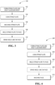
- FIG. 3 illustrates a first method 100 for forming the golf club head assembly 10.
- This first method 100 includes a first step 102 of forming the strike plate 30 and the club head body 14.
- the strike plate 30 and/or club head body 14 may be formed using processes such as machining, casting, stamping, injection molding (metal and/or polymer), direct laser sintering, powder metal forming processes, or other appropriate process known to those skilled in the art.
- the strike plate blank may then be coined in step 104.
- coining is form of precision stamping, wherein the strike plate 30 is subjected to a high force causing it to plastically deform. The coining process is used to create the bulge and roll radius described above.
- the strike plate 30 may then be milled or machined in step 106 to provide a precision contour and surface texture.
- the machining process uses a rotary cutter to remove material from the strike plate 30 and is generally performed using a CNC system to control the process.
- the strike plate 30 may then be welded into the opening 36 of the frame 32 in step 108.
- the strike plate 30 is aligned with the opening 36 of the frame 32 and abuts the lip 38.
- the strike plate 30 is secured to the frame 32 by welding along the perimeter of the opening 36 forming the golf club head 10.
- the welding step may utilize a pulse plasma or laser welding process.
- a golf club head assembly 10 formed from the method 100 illustrated in FIG. 3 will include a strike face 12 that has at least two different surface finishes (i.e., the original and/or ground finish of the frame 32 and the machined/milled finish of the strike plate 30).
- FIG. 4 schematically illustrates a second method 200 for forming a golf club head 10.
- the method 200 illustrated in FIG. 4 is similar in many respects to the first method 100 illustrated in FIG. 3 , except the machining/milling of step 106 is performed after the strike plate 30 is welded to the frame 32 in step 108. In doing so, the grinding process of step 110 may be optionally removed, and the surface texture of the strike plate 30 may be optionally extended across the frame 32 in a continuous manner.
- the second method 200 generally begins by forming the strike plate 30 and golf club head body 14 in step 202, such as by machining, casting, stamping, injection molding (metal and/or polymer), direct laser sintering, powder metal forming processes, or other appropriate process known to those skilled in the art.
- the strike plate 30 may then be coined in step 204, as described above in step 104 of FIG. 3 .
- the coined strike plate 30 may then be welded into the opening 36 provided in the frame 32 in step 206. Any remaining weld bead/line may then be optionally removed via a grinding process 208 (illustrated in phantom to indicate that this process is not a strictly required step). And finally, the entire ball striking surface 34 may be machined/milled in step 210. In some embodiments, this machining step 210 may be operative to remove any weld bead that was not removed via optional step 208.
- this manufacturing method 200 may create a surface texture with no or little regard for the specific location of the weld line/perimeter of the strike plate 30.
- the surface texture may be uniform and continuous across both the strike plate 30 and frame 32, may continuously vary as a function of a distance from face center, or take any other pattern as may be found desirable.
- these milling patterns need not be constrained by the size and location of the strike plate perimeter.
- Milling or machining the entire strike face 12, such as through the second method 200 of FIG. 4 provides an additional benefit of further tightening/reducing the profile/curvature tolerances for the bulge and roll radius (i.e., to provide a more precise curvature). Having the textured surface across the entire strike face 12 while maintaining a lower tolerance for the bulge and roll radius can create a higher performing club head assembly 10 that provides greater distance, spin control, and forgiveness.
- a milled strike plate 30 has a surface texture that can be characterized by one or more directional cutting patterns and a surface texture that is directionally dependent.
- Typical milling processes utilize a rotary cutting tool to remove material from the strike plate 30.
- This process can be automated using a Computer Numerical Control (CNC) system to provide enhanced precision, consistency, and repeatability across multiple club heads.
- CNC Computer Numerical Control
- the CNC machining process can ensure that a predominant pattern direction, surface texture, and overall face contour precisely match the predetermined specifications. This level of enhanced precision is desirable because it has been found that the predominant pattern direction and surface texture on the strike plate 30 can meaningfully impact the spin characteristics on the golf ball after impact. Therefore, given the level of manufacturing control and repeatability that is afforded by CNC milling, it is possible to customize the textured surface on the strike plate 30 to an individual's swing type, which may result in longer and straighter ball flight patterns.
- a typical milling pattern may resemble a plurality of grooves that are concentrically or linearly cut into the outer surface. These patterns may more specifically comprise a plurality of primary peaks and primary valleys that each extend along a linear or curvilinear path.
- each primary peak may include a plurality of secondary valleys that are disposed in a regular pattern along at least a portion of the length of the peak
- each primary valley may include a plurality of secondary peaks that are disposed in a regular pattern along at least a portion of the length of the valley.
- the plurality of peaks and valleys can range from -100 ⁇ -in to 100 ⁇ -in (about -2.54 ⁇ m to about 2.54 ⁇ m), -140 ⁇ -in to 140 ⁇ -in (about -3.56 ⁇ m to about 3.56 ⁇ m), -200 ⁇ -in to 200 ⁇ -in (about -5.08 ⁇ m to about 5.08 ⁇ m), -500 ⁇ -in to 500 ⁇ -in (about -12.7 ⁇ m to about 12.7 ⁇ m), -700 ⁇ -in to 700 ⁇ -in (about -17.78 ⁇ m to about 17.78 ⁇ m), -1000 ⁇ -in to 1000 ⁇ -in (about -25.4 ⁇ m to about 25.4 ⁇ m), -1400 ⁇ -in to 1400 ⁇ -in (about -35.56 ⁇ m to
- the surface texture across the ball striking surface 34 may be uniform across the entire strike plate 30, in other embodiments, however, the ball striking surface 34 may have a surface texture that functionally varies across the strike face 12.
- the surface texture may vary from a center region of the strike plate 30 towards the perimeter of the strike plate 30.
- the surface roughness can vary on the strike plate 30 from near the toe portion 20 of the club head 10 to near the heel portion 22 of the club head 10.
- the surface roughness can vary on the strike plate 30 from near the sole 28 of the club head 10 to near the crown 26 of the club head 10.
- surface roughness can vary in any combination of the aforementioned examples.
- surface roughness can be uniform in certain areas of the strike plate 30, and vary in other areas of the strike plate 30.
- the textured surface of the strike plate 30 may have a uniform roughness of about 148 ⁇ -in (about 3.76 ⁇ m).
- the textured surface can have a surface roughness between about 50 ⁇ -in and about 300 ⁇ -in (between about 1.27 ⁇ m and about 7.62 ⁇ m).
- the textured surface can have a surface roughness between 25-350, 25-50, 50-75, 75-100, 75-100, 100-125, 125-150, 150-175, 175-200, 200-225, 225-250, 250-275, 275-300, 300-325 ⁇ -in, 25-150, 150-350, 75-250, 25-125, 125-225, 225-350, 75-150, 150-225, or 225-300.
- the roughness can be 25, 50, 75, 100, 125, 150, 175, 200, 225, 250, 275, 300, 325, or 350 ⁇ -in.
- the surface roughness can be between about 140 ⁇ -in and about 300 ⁇ -in (between about 3.56 ⁇ m and about 7.62 ⁇ m).
- the predominant pattern direction of the textured surface in any particular area may comprise one or more linear, curvilinear, or intersecting patterns to form a milling pattern 250.
- these patterns may extend somewhat uniformly across the entire strike face 12. In other embodiments, however, these patterns may be zonal, or may vary across the face due to a curvilinear and concentric nature.
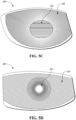
- the milling pattern 250 may comprise a center portion 252 that is surrounded by a peripheral portion 254, such as shown in FIGS. 5C-5J .
- the milling profiles illustrated in FIGS. 5A-5J are examples of different milling patterns 250 that may be employed to meet different design objectives, as will be discussed below.
- the central portion comprises a concentric milling pattern and the peripheral portion comprises a linear milling pattern.
- a milling pattern 250 may include a plurality of peaks and valleys that are oriented in a linear manner between the crown 26 and the sole 28.
- FIG. 5B then illustrates an embodiment where this pattern is turned 90 degrees and extends between the heel portion 22 and toe portion 20.
- FIGS. 5A-5B further illustrate a channel 256 that may be disposed around a perimeter of the milling pattern 250 to provide a more clear transition between the milling pattern 250 and the remainder of the club 10.
- an edge portion 258 of the forward most surface i.e. the ball striking surface 34
- Such a surface may instead be polished or sandblasted to more readily blend into the body.
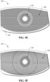
- FIG. 5C-5J more clearly illustrate examples of milling patterns 250 that have different variations of a center portion 252 and a peripheral portion 254.
- the center portion 252 may be round.
- the center portion 252 may have a rounded polygonal design, such as a rounded triangle or a rounded square (or a rounded pentagon, hexagon, heptagon, octagon, or the like).
- the milling pattern 250 within the center portion 252 may comprise a linear pattern ( FIGS.
- FIGS. 5C , 5H , and 5J a concentric pattern, for example, beginning at an outer perimeter of the center portion 252 ( FIGS. 5G and 5I ), or a radial pattern originating from a point, line, or area ( FIGS. 5D-5F ).
- the peripheral portion 254 may comprise one or more zones 260 between which the milling pattern may change direction/orientation, change type, or begin anew.
- FIGS. 5H-5J illustrate three peripheral designs that include a plurality of zones 260, where a linear pattern is rotated between each zone 260.
- FIG. 5C illustrates an emanating ray pattern (i.e., where the milling lines emanate linearly from a central point or area.
- FIG. 5D illustrates a linear arrangement across the peripheral portion 254.
- FIG. 5E illustrates an intersecting linear arrangement (i.e., where a first linear arrangement is cut, and then a second linear arrangement in a second orientation is cut over top of the first linear arrangement).
- FIG. 5F illustrates intersecting curvilinear arrangements (i.e., where the first curvilear arrangement is cut from toe to heel, and the second is cut from heel to toe - note that similar arrangements may be made by cutting from crown to sole and sole to crown, or from various corners).
- FIG. 5G illustrates a concentric pattern emanating from a central point or area.
- the strike face 12 of the golf club head assembly 10 can comprise two or more different surface finishes/textures.
- the strike plate 30 can be milled or machined, creating a first surface finish prior to being welded to the opening 36 of the frame 32.
- the remaining portion of the strike face 12 which was not milled may then have a second surface finish, such as a smooth or sand blasted surface finish.
- Having the different textured surfaces on the strike face 12 can provide the player with a visual alignment aid to help position the golf ball at the center of the strike face 12.
- the entire ball striking surface 34 (including the frame 32 and strike plate 30) can comprise the textured surface from the milling or machining process.
- the surface texture and milling pattern created by the tool can introduce a considerable amount of variability in the resulting spin and launch characteristics of an impacted ball.
- two clubs with milling patterns oriented 90 degrees apart may produce significantly different ball launch characteristics.
- differences in the feed rate, cutting depth, tool diameter, end profile, and the tool spindle speed used to create the pattern can introduce variations in the surface texture that affect ball flight.
- Table 1 illustrates 4 identical driver designs (i.e., similar volume, mass distribution, structure, and loft), one with a traditional brushed surface finish across the strike face 12 (i.e, the control club), and three with different milled surface finishes across the strike face 12.
- R A the average surface roughness
- milled 1 attempted to match the average roughness of the brushed surface finish as closely as possible. Despite the close average roughness, the milled face produced about 10.7% less spin than the brushed face. This decrease in spin rate was an unexpected result. Then, milled faces 2 and 3 were constructed to increase the average roughness, as the prevailing belief was that, as average roughness increases, spin imparted by a driver should decrease. Milled faces 2 and 3, however, both resulted in about 5% more spin than the lower roughness milled face (milled 1). From this analysis, it was determined that average surface roughness may not be suitable to fully characterize the spin-effects caused by the surface texture of a driver face (which is counter to the prevailing understanding).
- a new manner of characterizing the surface texture of a strike face has been developed to more effectively predict the resulting spin imparted to a golf ball by a strike face. Furthermore, embodiments of the present design utilize this new characterization to provide a golf club with a face that is optimized to meet one or more spin-based design objectives.
- R A represents an arithmetic average value of absolute surface deviations relative to a mean center line.
- a suitable cut-off wavelength may be about 0.762 mm (about 0.03 inches ).
- W Void is a parameter that has been developed to represent the average profile void depth 300 relative to a reference surface 302 that is created by applying a morphological closing filter to the actual surface profile 304.
- Morphologic closing is generally an image processing technique that may be best analogized as a disc 306 (in 2D) or sphere (in 3D) of a predetermined radius 308 (i.e., radius of curvature) being theoretically rolled across the actual surface profile 304.
- the lower envelope formed by the rolling disc then generates the "closed" reference surface 302.
- W Void may be calculated by summing the total void area 310 between the closed reference surface 302 the actual surface profile 304 and dividing that aggregated area by the length of the surface (i.e., the length of a mean center line 312).
- W VDCL is a parameter that has been developed to represent the ratio of the contact length 314 (in 2D) or area (in 3D) between the closed reference surface 302 (as described above with respect to W Void and FIG. 5 ) and the actual surface profile 304, to the length (in 2D) or area (in 3D) of the surface itself (i.e., measured along a mean center line 312).
- W VDCL For a perfectly flat surface, W VDCL would equal 1.0; for a wavy surface (e.g., where the radius of curvature 308 of the disc/sphere is smaller than any external radius of curvature of the surface), W VDCL may be greater than 1.0; and, for a surface with a rather fine texture (e.g., where the radius of curvature 308 of the disc/sphere is greater than an external radius of curvature for a portion of the surface), W VDCL may be less than 1.0.
- each parameter may be calculated in a number of directionally dependent manners. More specifically, the surface profiles illustrated in FIGS. 6 and 7 may be presumed to have been taken from a 2-D cutting plane through a strike face 12, similar to the strike face 12 shown in FIG. 1 . If this cutting plane is oriented perpendicular to the dominant milling grooves, all three surface parameters may differ from measurements where the cutting plane is oriented parallel to the milling grooves, which may differ still from a 3D computation where any closed reference surface is generated by a theoretical sphere.
- a face-centric coordinate system 400 such as shown in FIG. 8 may be utilized to better explain how the parameters are derived.
- the face-centric coordinate system 400 may have an origin that is coincident with the geometric face center, X and Y axes 402, 404 that are each tangential to the ball striking surface 34 at the face center, and a Z-axis 406 that is normal to the ball striking surface at 34 the face center.
- the X-axis 402 may further be parallel to a ground plane 408 when the club is held at address according to prescribed loft and lie angles, and may generally extend between the heel and the toe.
- the Y-axis 404 is orthogonal to the X-axis 402, and is generally the projection of a vertical reference line 410 onto the ball striking surface 34 when the club is held at address.
- each may be computed along a 2D line (e.g., computed within a single 2D slice taken in the Y-Z plane), averaged across a plurality of 2D lines (e.g., averaged across a plurality of 2D slices taken in adjacent Y-Z planes), or computed in 3D across the entire face (i.e., not directionally-dependent).
- a 2D line e.g., computed within a single 2D slice taken in the Y-Z plane
- averaged across a plurality of 2D lines e.g., averaged across a plurality of 2D slices taken in adjacent Y-Z planes
- computed in 3D across the entire face i.e., not directionally-dependent
- R A /W Void and W VDCL both provide slightly different approximations of the amount of surface area that a golf ball may directly contact (at a microscopic level) during an impact (i.e., thus providing a more accurate estimation of the actual contact friction experienced between the ball and the face during an impact). More specifically, the "closed" reference surface 302 may approximate a compliant object (i.e., a polymeric, compressible golf ball) that is in forcible contact with the surface texture and deforms about the peaks.
- a compliant object i.e., a polymeric, compressible golf ball
- W VDCL a radius of curvature for W VDCL of about 0.508 mm (about 0.02 inches) to form the reference surface 302
- the value of W VDCL correlates to the amount of spin imparted to an impacted golf ball by a low lofted golf club, such as a driver. More specifically, as W VDCL increases, imparted spin decreases, such as generally illustrated in Table 3.
- the figures in Table 3 were all calculated within a Y-Z cutting plane that passed through face center for drivers with similar overall geometries, constructions, and mass properties.
- a golf club head 10 may include a milled ball striking surface 34 that has a surface texture characterized by a R A to W Void ratio and/or by a W VDCL value that is customized to suit a particular design objective.
- any numeric values assume a about 0.762 mm (0.03 inch) high-pass cutoff filter for R A , a about 0.127 mm (0.005 inch) radius of curvature for creating the reference surface for W Void , and a about 0.508 mm (0.02 inch) radius of curvature for creating the reference surface for W VDCL .
- a low-lofted club such as a low-loft driver (i.e., having a loft angle of from about 8 to about 14 degrees, or from about 8 to about 12 degrees, or from about 8 to about 10 degrees), may be specifically designed to have a low backspin tendency by including a milled strike face with surface texture characterized by an R A to W Void ratio, measured in a Y-Z plane through the face center, that is greater than about 4, or greater than about 5, or greater than about 6, or greater than about 7, or greater than about 8, greater than about 9, or greater than about 10.
- the R A to W Void ratio can range from 4 to 12, 4 to 8, 8 to 12, 6 to 10, 4 to 6, 36 to 8, 8 to 10, or 10 to 12.
- the R A to W Void ratio can be 4, 6, 8, 10, or 12.
- this low-spin driver face surface texture may be characterized by a W VDCL value, measured in a Y-Z plane through the face center, that is greater than about 18%, or greater than about 20%, or greater than about 22%, or greater than about 24%, or greater than about 26%, or greater than about 28%, or greater than about 30%.
- the W VDCL value can range from 18% to 33%, 18% to 24%, 24% to 36%, 24% to 30%, 30% to 36%, or 27% to 33%.
- the W VDCL value can be 18%, 20%, 22%, 24%, 26%, 28%, 30%, 32%, 34%, or 36%.
- a metal wood intended to induce a greater amount of loft may be specifically designed to have a higher backspin tendency by including a milled strike face with a surface texture characterized by an R A to W Void ratio, measured in a Y-Z plane through the face center, that is less than about 4, or less than about 3, or less than about 2, or within a range of from about 1 to about 4, or from about 2 to about 4.
- this higher-spin face surface texture may be characterized by a W VDCL value, measured in a Y-Z plane through the face center, that is less than about 24%, or less than about 22%, or less than about 20%, or less than about 18%, or within a range of from about 20% to about 24%.
- the R A to W Void and W VDCL values may be an average of the values across a plurality of Y-Z slices. For example, these values may be averaged across a center strip, region, or portion of the face 12. For example, these values may be averaged across a 42.67 mm (1.68 inch) impact zone, measured along the X-axis, and centered about face center. Likewise, in some variations, these low or high backspin surface textures may be localized within a center portion 252 of the face, such as within a 42.67mm (1.68 inch) diameter circle centered about the face center. Alternatively, these values may be averaged across a narrower center portion of the impact zone that may measure about about 9.53 mm (0.375 inches) along the X-axis or in diameter.
- a strike face 12 may include a milled surface texture characterized by an R A to W Void ratio, measured in an X-Z plane through the face center, that is greater than about 4, or greater than about 5, or greater than about 6, or greater than about 7, or greater than about 8, greater than about 9, or greater than about 10. Additionally, or alternatively, this surface texture with directionally increased contract friction may be characterized by a W VDCL value, measured in an X-Z plane through the face center, that is greater than about 18%, or greater than about 20%, or greater than about 22%, or greater than about 24%, or greater than about 26%, or greater than about 28%, or greater than about 30%.
- the W VDCL value can range from 18% to 33%, 18% to 24%, 24% to 36%, 24% to 30%, 30% to 36%, or 27% to 33%.
- the W VDCL value can be 18%, 20%, 22%, 24%, 26%, 28%, 30%, 32%, 34%, or 36%.
- a strike face 12 may include a milled surface texture characterized by an R A to W Void ratio, measured in an X-Z plane through the face center, that is less than about 4, or less than about 3, or less than about 2, or within a range of from about 1 to about 4, or from about 2 to about 4.
- this surface texture with directionally decreased contract friction may be characterized by a W VDCL value, measured in an X-Z plane through the face center, that is less than about 24%, or less than about 22%, or less than about 20%, or less than about 18%, or within a range of from about 20% to about 24%.
- contact friction may be promoted or discouraged in other locations or areas about the strike face 12 via changes in the surface texture.
- the surface texture in a peripheral region (or peripheral portion 254) of the strike face 12 e.g., outside of the central region or narrower, center portion 252 may be controlled to provide enhanced forgiveness, alter spin profiles, and/or to offset other design parameters of the club head 10.
- contact friction may be increased in the peripheral region by providing an R A to W Void ratio, measured in the Y-Z plane and/or in the X-Z plane and averaged across at least a portion of the peripheral region, of greater than about 4, or greater than about 5, or greater than about 6, or greater than about 7, or greater than about 8, greater than about 9, or greater than about 10.
- this increased friction peripheral region may have a surface texture characterized by a W VDCL value, measured in the Y-Z plane and/or in the X-Z plane and averaged across at least a portion of the peripheral region, that is greater than about 18%, or greater than about 20%, or greater than about 22%, or greater than about 24%, or greater than about 26%, or greater than about 28%, or greater than about 30%.
- the W VDCL value can range from 18% to 33%, 18% to 24%, 24% to 36%, 24% to 30%, 30% to 36%, or 27% to 33%.
- the W VDCL value can be 18%, 20%, 22%, 24%, 26%, 28%, 30%, 32%, 34%, or 36%.
- the increased friction peripheral region may specifically include one or more of an increased friction portion abutting the sole 28, an increased friction portion abutting the toe portion 20, an increased friction portion abutting the crown 26, and/or an increased friction portion abutting the heel portion 22.
- the increased contact friction in the peripheral region may be used to, for example, provide additional design flexibility in altering the bulge and/or roll radius of curvature of the strike face 12 or the center of gravity of the club head 10, or in increasing the forgiveness to certain impacts.
- contact friction may be decreased in the peripheral region by providing an R A to W Void ratio, measured in the Y-Z plane and/or in the X-Z plane and averaged across at least a portion of the peripheral region, of less than about 4, or less than about 3, or less than about 2, or within a range of from about 1 to about 4, or from about 2 to about 4. Additionally, or alternatively, this decreased friction peripheral region may have a surface texture characterized by a W VDCL value, measured in the Y-Z plane and/or in the X-Z plane and averaged across at least a portion of the peripheral region, that is less than about 24%, or less than about 22%, or less than about 20%, or less than about 18%, or within a range of from about 20% to about 24%.
- the decreased friction peripheral region may specifically include one or more of a decreased friction portion abutting the sole 28, a decreased friction portion abutting the toe portion 20, a decreased friction portion abutting the crown 26, and/or a decreased friction portion abutting the heel portion 22.
- an average R A to W Void ratio and/or W VDCL value from within the central region or narrower, center portion 252 of the strike face 12 may be different than the average R A to W Void ratio and/or W VDCL value from within a portion of the peripheral region of the strike face 12.
- the R A to W Void ratio and/or W VDCL value may vary as a function of an increasing distance from the geometric center of the strike face 12.
- an average R A to W Void ratio and/or W VDCL value (measured in one or both of the Y-Z plane and the X-Z plane) may be greater proximate the toe portion 20 and/or heel portion 22 than in the center of the strike face 12.
- the R A to W Void ratio and W VDCL value for a particular face may be customized during a milling process by altering one or more of the tool (e.g., a ball end mill, a square end mill, or a corner round end mill), the angle of the tool relative to the face (e.g., from greater than about 0 degrees relative to the face to about 90 degrees), the cutting speed (e.g., from about 60 to about 300 inches per minute for titanium, or from about 300 to about 1000 inches per minute for steel), the stepover (e.g., from about 0.005 inch to about 0.125 inch), and the travel velocity (e.g., from about 0.005 to about 0.010 inch/minute).
- the tool e.g., a ball end mill, a square end mill, or a corner round end mill
- the angle of the tool relative to the face e.g., from greater than about 0 degrees relative to the face to about 90 degrees
- the cutting speed e.g., from about 60 to about 300 inches per minute
- R A to W Void ratio and W VDCL correlate well with the spin that may be imparted to an impacted golf ball
- the milling pattern/surface texture provided on the face may be specifically controlled to support the design objectives of the club head.
- a set of golf clubs may comprise three golf clubs, each having a different loft angle (L), where L 1 ⁇ L 2 ⁇ L 3 .
- each golf club may have a progressively decreasing R A /W Void ratio (i.e., where (R A /W Void ) 1 > (R A /W Void ) 2 > (R A /W Void ) 3 ), and/or a progressively decreasing W VDCL value (i.e., where W VDCL1 > W VDCL2 > W VDCL3 ).
- At least the first of the three clubs is a wood-style club, and may be a driver having a loft of from about 8 degrees to about 12 degrees.
- at least the third golf club of the set may be an iron-type golf club.
- L 3 may be less than or equal to about 24 degrees.
- all three clubs in the set may be wood-style golf clubs or all three may be iron-style golf clubs.
- a high-lofted iron i.e., having a loft angle of from about 30 to about 64 degrees, or from about 34 to about 64 degrees, or from about 39 to about 64 degrees
- a high backspin tendency by including a milled strike face with surface texture characterized by an R A to W Void ratio, measured in a Y-Z plane through the face center, that is greater than about 4, or greater than about 5, or greater than about 6, or greater than about 7, or greater than about 8, greater than about 9, or greater than about 10.
- the R A to W Void ratio can range from 4 to 12, 4 to 8, 8 to 12, 6 to 10, 4 to 6, 36 to 8, 8 to 10, or 10 to 12.
- the R A to W Void ratio can be 4, 6, 8, 10, or 12.
- this high-spin iron face surface texture may be characterized by a W VDCL value, measured in a Y-Z plane through the face center, that is greater than about 18%, or greater than about 20%, or greater than about 22%, or greater than about 24%, or greater than about 26%, or greater than about 28%, or greater than about 30%.
- the W VDCL value can range from 18% to 33%, 18% to 24%, 24% to 36%, 24% to 30%, 30% to 36%, or 27% to 33%.
- the W VDCL value can be 18%, 20%, 22%, 24%, 26%, 28%, 30%, 32%, 34%, or 36%.
- a set of golf clubs may comprise three golf clubs, each having a different loft angle (L), where L 1 ⁇ L 2 ⁇ L 3 .
- each golf club may have an R A /W Void ratio where (R A /W Void ) 1 > (R A /W Void ) 2 and (R A /W Void ) 3 > (R A /W Void ) 2 .
- each club may have a W VDCL value where W VDCL1 > W VDCL2 and W VDCL3 > W VDCL2 .
- At least the first of the three clubs is a wood-style club, and may be a driver having a loft of from about 8 degrees to about 12 degrees
- the third of the three clubs is an iron-type club having a loft of from about 30 to about 64 degrees, or from about 34 to about 64 degrees, or from about 39 to about 64 degrees.
- golf equipment related to the apparatus, methods, and articles of manufacture described herein may be conforming or non-conforming to the rules of golf at any particular time. Accordingly, golf equipment related to the apparatus, methods, and articles of manufacture described herein may be advertised, offered for sale, and/or sold as conforming or non-conforming golf equipment.
- the apparatus, methods, and articles of manufacture described herein are not limited in this regard.
- the apparatus, methods, and articles of manufacture described herein may be applicable to other types of golf club such as a driver wood-type golf club, a fairway wood-type golf club, a hybrid-type golf club, an iron-type golf club, a wedge-type golf club, or a putter-type golf club.
- the apparatus, methods, and articles of manufacture described herein may be applicable to other types of sports equipment such as a hockey stick, a tennis racket, a fishing pole, a ski pole, etc.
Landscapes
- Health & Medical Sciences (AREA)
- General Health & Medical Sciences (AREA)
- Physical Education & Sports Medicine (AREA)
- Engineering & Computer Science (AREA)
- Life Sciences & Earth Sciences (AREA)
- Wood Science & Technology (AREA)
- Mechanical Engineering (AREA)
- Golf Clubs (AREA)
Claims (13)
- Golfschlägerkopf (10), der Folgendes umfasst:eine Schlagfläche (12), die eine Ballschlagfläche (34) aufweist, die eingesetzt wird, um einen Golfball zu treffen, wobei die Ballschlagfläche (34) in einem Loft-Winkel von 8 Grad bis 14 Grad angeordnet ist und eine Oberflächentextur aufweist, die für Fräsen charakteristisch ist, die eine Vielzahl von Erhebungen und Vertiefungen, die sich jeweils in eine lineare oder kurvilineare Richtung erstrecken, und eine Referenz-Mittelebene umfasst, die sich zwischen der Vielzahl von Erhebungen und der Vielzahl von Vertiefungen erstreckt, wobei ein Abstand unterhalb der Referenz-Mittelebene negativ ist und ein Abstand oberhalb der Referenz-Mittelebene positiv ist, und wobei sich die Vielzahl von Erhebungen und die Vielzahl von Vertiefungen über einen durchschnittlichen maximalen Abstand von -25,4 µm (-1.000 Mikrozoll) bis 25,4 µm (1.000 Mikrozoll) von der Mittelebene erstrecken;wobei die Oberflächentextur (250) ferner einen Mittelabschnitt (252) umfasst, der von einem Umfangsabschnitt (254) umgeben ist; wobei der Mittelabschnitt (252) ein konzentrisches Fräsmuster aufweist; und wobei der Umfangsabschnitt (254) ein lineares Fräsmuster aufweist;wobei die Oberflächentextur über den Mittelabschnitt hinweg einheitlich ist, wenn sie entlang eines am Mittelabschnitt vorherrschenden Fräsmusters gemessen wird, und die Oberflächentextur über den Umfangsabschnitt hinweg einheitlich ist, wenn sie entlang eines am Umfangsabschnitt vorherrschenden Fräsmusters gemessen wird, und eine durchschnittliche Oberflächenrauigkeit, RA, die einen arithmetischen Mittelwert von absoluten Oberflächenabweichungen relativ zu einer mittleren Mittellinie repräsentiert und unter Verwendung eines Hochpassfilters mit einem Grenzwert von 0,762 mm gemessen wird, einen Oberflächenhohlraumparameter, WVoid, der eine durchschnittliche Tiefe der Vielzahl von Vertiefungen relativ zu einer geschlossenen Referenzoberfläche angibt, die unter Verwendung eines morphologischen Schließfilters, der auf die Oberflächentextur angewendet wird, erzeugt wird, wobei die geschlossene Referenzoberfläche als theoretische Scheibe mit vorbestimmtem Radius definiert ist, der über die Oberflächentextur abgerollt ist, wobei der Oberflächenhohlraumparameter, WVoid, unter Verwendung eines Schließfilters mit einem Radius von 0,127 mm gemessen wird, und einen Oberflächenkontaktparameter, WVDCL, aufweist, der das Kontaktausmaß zwischen der geschlossenen Referenzoberfläche und der Oberflächentextur repräsentiert, und unter Verwendung eines Schließfilters mit einem Radius von 0,508 mm gemessen wird;wobei die Oberflächentextur, die innerhalb einer vertikalen Schnittebene, die sich durch einen geometrischen Mittelpunkt der Oberfläche erstreckt, gemessen wird, durch zumindest eines der Folgenden definiert wird:
einem Verhältnis von RA zu WVoid, das größer als etwa 4 ist; oder wobei der WVDCL-Parameter größer als etwa 24 % ist. - Golfschlägerkopf (10) nach Anspruch 1, wobei die Oberflächentextur (250), gemessen innerhalb einer vertikalen Schnittebene, die von dem geometrischen Mittelpunkt der Oberfläche versetzt ist, durch zumindest eines der Folgenden gekennzeichnet ist: einem Verhältnis von RA zu WVoid kleiner als etwa 4; oder einem WVDCL-Parameter kleiner als etwa 24 %.
- Golfschlägerkopf (10) nach einem der Ansprüche 1 bis 2, wobei die Oberflächentextur (250), gemessen innerhalb einer vertikalen Schnittebene, die vom geometrischen Mittelpunkt der Oberfläche versetzt ist, dadurch gekennzeichnet ist, dass das Verhältnis von RA zu WVoid größer ist als das Verhältnis von RA zu WVoid, das innerhalb der Ebene gemessen wird, die den geometrischen Mittelpunkt schneidet; oder dass der WVDCL-Parameter größer ist als der WVDCL-Parameter, der innerhalb der Ebene gemessen wird, die den geometrischen Mittelpunkt schneidet.
- Golfschlägerkopf (10) nach einem der Ansprüche 1 bis 3, wobei die Oberflächentextur (250), die innerhalb der vertikalen Schnittebene gemessen wird, die sich durch den geometrischen Mittelpunkt der Oberfläche erstreckt, ferner durch eine RA von zwischen etwa 140 Mikrozoll und etwa 300 Mikrozoll gekennzeichnet ist.
- Golfschlägerkopf (10) nach einem der Ansprüche 1 bis 4, wobei der Loft-Winkel etwa 8 Grad bis etwa 14 Grad beträgt.
- Golfschlägerkopf (10) nach einem der Ansprüche 1 bis 5, wobei die Ballschlagfläche (34) einen ersten Bereich, der eine erste Oberflächentextur aufweist, und einen zweiten Bereich, der eine zweite Oberflächentextur aufweist, umfasst; und
wobei zumindest eines aus: einem durchschnittlichen Verhältnis von RA zu WVoid, das innerhalb einer vertikalen Schnittebene gemessen wird, im ersten Bereich und im zweiten Bereich unterschiedlich ist; oder einem durchschnittlichen WVDCL-Parameter, der innerhalb einer vertikalen Schnittebene gemessen wird, in dem ersten Bereich und dem zweiten Bereich unterschiedlich ist. - Golfschlägerkopf (10) nach einem der Ansprüche 1 bis 6, wobei der zweite Bereich den ersten Bereich umgibt.
- Golfschlägerkopf (10) nach einem der Ansprüche 1 bis 7, der ferner Folgendes umfasst:einen Schlägerspitzenabschnitt (20), einen Fersenabschnitt (22), einen Scheitel (26) und eine Sohle (28);einen Körper, der mit der Schlagfläche zusammenwirkt, um ein hohles Innenvolumen des Schlägerkopfs zu definieren, wobei die Schlagfläche ferner die Ballschlagfläche (34), die eine Oberflächentextur aufweist, die für Fräsen charakteristisch ist, umfasst;wobei die Oberflächentextur über den Mittelabschnitt hinweg einheitlich ist, wenn sie entlang eines am Mittelabschnitt vorherrschenden Fräsmusters gemessen wird, und die Oberflächentextur über den Umfangsabschnitt hinweg einheitlich ist, wenn sie entlang eines am Umfangsabschnitt vorherrschenden Fräsmusters gemessen wird, und die die Vielzahl von Erhebungen und die Vielzahl von Vertiefungen umfasst, und die Referenz-Mittelelebene sich zwischen der Vielzahl von Erhebungen und der Vielzahl von Vertiefungen erstreckt, wobei der Abstand unterhalb der Referenz-Mittelebene negativ ist und der Abstand oberhalb der Referenz-Mittelebene positiv ist, und wobei sich die Vielzahl von Erhebungen und die Vielzahl von Vertiefungen über einen durchschnittlichen maximalen Abstand von zumindest - 5,08 µm (-200 Mikrozoll) bis zumindest 5,08 µm (200 Mikrozoll) von der Mittelebene erstrecken; undwobei die Oberflächentextur, die innerhalb zumindest einer aus einer vertikalen Schnittebene oder einer zweiten Schnittebene, die orthogonal zu der vertikalen Schnittebene sowie zu der Ballschlagfläche ist, gemessen wird, durch zumindest eines der Folgenden gekennzeichnet ist: einem Verhältnis von RA zu WVoid größer als etwa 4; oder einem WVDCL-Parameter größer als etwa 24 %.
- Golfschlägerkopf (10) nach Anspruch 8, wobei die Oberflächentextur ferner durch eines der Folgenden gekennzeichnet ist: dem Verhältnis von RA zu WVoid größer als etwa 8; oder dem WVDCL-Parameter größer als etwa 28 %.
- Golfschlägerkopf (10) nach einem der Ansprüche 8 bis 9, wobei die Vielzahl von Erhebungen eine Vielzahl von kleineren Vertiefungen umfasst; und wobei die Vielzahl von Vertiefungen eine Vielzahl von kleineren Erhebungen umfasst.
- Golfschlägerkopf (10) nach einem der Ansprüche 8 bis 10, wobei die Oberflächentextur als Funktion eines Abstands von einem geometrischen Mittelpunkt der Oberfläche variiert.
- Golfschlägerkopf (10) nach einem der Ansprüche 8 bis 11, wobei die Schlagfläche ferner einen Mittelabschnitt umfasst, der von einem Umfangsabschnitt umgeben ist; und
wobei die Oberflächentextur ferner durch zumindest eines aus dem Verhältnis von RA zu WVoid oder dem WVDCL-Parameter, das/der innerhalb des Umfangsabschnitts größer ist als innerhalb des Mittelabschnitts, gekennzeichnet ist. - Golfschlägerkopf (10) nach einem der Ansprüche 8 bis 12, wobei die Schlagfläche eine Schlagplatte und einen Rahmen umfasst, der die Schlagplatte umgibt, wobei die Schlagplatte innerhalb einer Öffnung, die in dem Rahmen bereitgestellt ist, derart befestigt ist, dass die Schlagplatte und der Rahmen zusammenwirken, um die Ballschlagfläche (34) zu definieren.
Applications Claiming Priority (2)
| Application Number | Priority Date | Filing Date | Title |
|---|---|---|---|
| US201662435944P | 2016-12-19 | 2016-12-19 | |
| PCT/US2017/067433 WO2018119002A1 (en) | 2016-12-19 | 2017-12-19 | Localized milled golf club face |
Publications (3)
| Publication Number | Publication Date |
|---|---|
| EP3554655A1 EP3554655A1 (de) | 2019-10-23 |
| EP3554655A4 EP3554655A4 (de) | 2020-08-12 |
| EP3554655B1 true EP3554655B1 (de) | 2024-01-31 |
Family
ID=62556565
Family Applications (1)
| Application Number | Title | Priority Date | Filing Date |
|---|---|---|---|
| EP17884672.1A Active EP3554655B1 (de) | 2016-12-19 | 2017-12-19 | Lokalisierte gefräste golfschlägerseite |
Country Status (6)
| Country | Link |
|---|---|
| US (6) | US10343034B2 (de) |
| EP (1) | EP3554655B1 (de) |
| JP (4) | JP7016869B2 (de) |
| KR (1) | KR102515880B1 (de) |
| GB (3) | GB2571496B (de) |
| WO (1) | WO2018119002A1 (de) |
Families Citing this family (23)
| Publication number | Priority date | Publication date | Assignee | Title |
|---|---|---|---|---|
| US10888747B2 (en) | 2008-07-15 | 2021-01-12 | Taylor Made Golf Company, Inc. | Aerodynamic golf club head |
| US12036455B2 (en) * | 2014-04-28 | 2024-07-16 | Parsons Xtreme Golf, LLC | Golf club heads and methods to manufacture golf club heads |
| JP6386277B2 (ja) * | 2014-07-09 | 2018-09-05 | ブリヂストンスポーツ株式会社 | ゴルフクラブヘッド |
| JP2016221099A (ja) * | 2015-06-02 | 2016-12-28 | ブリヂストンスポーツ株式会社 | 製造方法、ゴルフクラブヘッド及び設計方法 |
| GB2571496B (en) * | 2016-12-19 | 2022-04-27 | Karsten Mfg Corp | Localized milled golf club face |
| US11161020B2 (en) | 2016-12-19 | 2021-11-02 | Karsten Manufacturing Corporation | Localized milled golf club face |
| US10857430B2 (en) | 2016-12-19 | 2020-12-08 | Karsten Manufacturing Corporation | Localized milled golf club face |
| US10213660B1 (en) * | 2017-01-13 | 2019-02-26 | Cobra Golf Incorporated | Golf club with aerodynamic features on club face |
| US10632352B2 (en) | 2017-04-28 | 2020-04-28 | Sumitomo Rubber Industries, Ltd. | Putter-type golf club head |
| US10668340B2 (en) | 2017-04-28 | 2020-06-02 | Sumitomo Rubber Industries, Ltd. | Putter-type golf club head |
| US11701557B2 (en) | 2017-08-10 | 2023-07-18 | Taylor Made Golf Company, Inc. | Golf club heads |
| US10874915B2 (en) | 2017-08-10 | 2020-12-29 | Taylor Made Golf Company, Inc. | Golf club heads |
| US10835787B1 (en) * | 2018-11-15 | 2020-11-17 | Cobra Golf Corporation | Golf club with perimeter face machining |
| JP6770600B2 (ja) * | 2019-01-29 | 2020-10-14 | 美津濃株式会社 | アイアンゴルフクラブヘッド |
| USD943693S1 (en) * | 2019-11-05 | 2022-02-15 | Cobra Golf Incorporated | Golf club |
| US11202944B1 (en) | 2020-06-15 | 2021-12-21 | Acushnet Company | Laser-contrasted golf club head and manufacturing process |
| US12109460B2 (en) * | 2020-06-15 | 2024-10-08 | Acushnet Company | Laser contrasted golf club head and manufacturing process |
| US11986707B2 (en) | 2020-08-21 | 2024-05-21 | Wilson Sporting Goods Co. | Faceplate of a golf club head |
| US11318358B1 (en) | 2020-12-29 | 2022-05-03 | Taylor Made Golf Company, Inc. | Golf club heads |
| US12138708B2 (en) * | 2022-02-23 | 2024-11-12 | Goodrich Corporation | Methods, systems, and apparatus for component manufacturing |
| USD1047039S1 (en) * | 2022-06-23 | 2024-10-15 | Peter Robin White | Golf club head |
| TWI892727B (zh) * | 2024-06-27 | 2025-08-01 | 大田精密工業股份有限公司 | 複合材料高爾夫球桿頭 |
| TWI884118B (zh) * | 2024-12-06 | 2025-05-11 | 大田精密工業股份有限公司 | 高爾夫球桿頭之打擊面的加工方法 |
Family Cites Families (156)
| Publication number | Priority date | Publication date | Assignee | Title |
|---|---|---|---|---|
| US2034936A (en) | 1931-07-15 | 1936-03-24 | George E Barnhart | Golf club |
| JPS57174687A (en) | 1981-04-20 | 1982-10-27 | Sumitomo Heavy Industries | Waste heat recovery equipment for sintering facility |
| JPS6125077A (ja) | 1984-07-13 | 1986-02-03 | Nec Corp | 試験装置 |
| JPS6125077U (ja) | 1984-07-17 | 1986-02-14 | 株式会社東芝 | 単相交流モ−タ |
| JPS62144674A (ja) * | 1985-12-19 | 1987-06-27 | マルマンゴルフ株式会社 | アイアンクラブヘッド |
| US20010014629A1 (en) * | 1989-06-12 | 2001-08-16 | Anderson Donald A. | Golf club head |
| US4964641A (en) | 1990-01-26 | 1990-10-23 | Diversified Metal Incorporated | Golf club with electrical discharge machined face |
| US5437088A (en) * | 1993-01-19 | 1995-08-01 | Igarashi; Lawrence Y. | Method of making a golf club that provides enhanced backspin and reduced sidespin |
| US5527034A (en) | 1993-11-30 | 1996-06-18 | Goldwin Golf U.S.A., Inc. | Golf club and method of manufacture |
| USD367304S (en) | 1994-09-13 | 1996-02-20 | Antonious Anthony J | Wood-type golf club head |
| GB9420733D0 (en) | 1994-10-14 | 1994-11-30 | Swash Harold | Golf clubs |
| US5709617A (en) * | 1995-07-27 | 1998-01-20 | The Yokohama Rubber Co., Ltd. | Wood type golf club head |
| US5688186A (en) * | 1996-04-02 | 1997-11-18 | Michaels; Richard A. | Golf club face |
| US5807190A (en) | 1996-12-05 | 1998-09-15 | The Beta Group | Golf club head or face |
| US5709616A (en) | 1996-05-31 | 1998-01-20 | Rife; Guerin D. | Groove configuration for a putter type golf club head |
| JPH10295858A (ja) * | 1997-04-25 | 1998-11-10 | Toyo A Tec Kk | ゴルフクラブヘッドおよびその製法 |
| CA2216293A1 (en) | 1997-09-23 | 1999-03-23 | John Saksun Sr. | Golf club head and method of making the same |
| US6224497B1 (en) | 1997-09-25 | 2001-05-01 | Anthony J. Antonious | Golf club head with improved frequency matched ball striking face characteristics |
| CA2246965C (en) | 1998-09-15 | 2001-08-28 | Leung Tom | Self-aligning, minimal self-torque golf clubs |
| JP2000176058A (ja) | 1998-12-14 | 2000-06-27 | Yokohama Rubber Co Ltd:The | ゴルフクラブヘッド |
| USD420079S (en) | 1999-01-22 | 2000-02-01 | Frank Frazetta | Golf club head |
| US6354961B1 (en) | 1999-06-24 | 2002-03-12 | Vardon Golf Company, Inc. | Golf club face flexure control system |
| US20020183134A1 (en) | 1999-06-24 | 2002-12-05 | Allen Dillis V. | Golf club head with face wall flexure control system |
| US6575845B2 (en) | 1999-11-01 | 2003-06-10 | Callaway Golf Company | Multiple material golf club head |
| US6443856B1 (en) | 1999-11-01 | 2002-09-03 | Callaway Golf Company | Contoured scorelines for the face of a golf club |
| JP2001170226A (ja) | 1999-12-15 | 2001-06-26 | Sumitomo Rubber Ind Ltd | ゴルフクラブヘッド |
| KR20010068605A (ko) | 2000-01-07 | 2001-07-23 | 김은미 | 골프 글러브의 스코어 라인 구조 |
| US6386987B1 (en) * | 2000-05-05 | 2002-05-14 | Lejeune, Jr. Francis E. | Golf club |
| US6428426B1 (en) | 2000-06-28 | 2002-08-06 | Callaway Golf Company | Golf club striking plate with variable bulge and roll |
| JP2002065909A (ja) | 2000-08-28 | 2002-03-05 | Gps:Kk | ゴルフクラブヘッド及びその製造方法 |
| JP2002153575A (ja) | 2000-11-20 | 2002-05-28 | Mizuno Corp | フェース面上に極細加工を施したゴルフクラブ |
| SE518176C2 (sv) | 2000-12-12 | 2002-09-03 | Stein Ahlqvist | Golfklubba |
| JP2002253709A (ja) | 2001-03-05 | 2002-09-10 | Mizuno Corp | ゴルフクラブヘッド |
| GB2373733B (en) | 2001-03-15 | 2004-08-18 | Douglas Boyd Buchanan | Putter head with pre-machined insert |
| WO2002100492A1 (en) * | 2001-06-11 | 2002-12-19 | Taylor Made Golf Company, Inc. | Golf club face and methods for making it |
| US6824475B2 (en) | 2001-07-03 | 2004-11-30 | Taylor Made Golf Company, Inc. | Golf club head |
| WO2003045507A1 (en) * | 2001-11-19 | 2003-06-05 | David Pelz | Golf club |
| US6840872B2 (en) | 2002-01-29 | 2005-01-11 | Yonex Kabushiki Kaisha | Golf club head |
| US6602149B1 (en) | 2002-03-25 | 2003-08-05 | Callaway Golf Company | Bonded joint design for a golf club head |
| US20040043831A1 (en) | 2002-08-22 | 2004-03-04 | Fu Sheng Industrial Co., Ltd. | Striking plate of a golf club head |
| US6997820B2 (en) | 2002-10-24 | 2006-02-14 | Taylor Made Golf Company, Inc. | Golf club having an improved face plate |
| US6904663B2 (en) | 2002-11-04 | 2005-06-14 | Taylor Made Golf Company, Inc. | Method for manufacturing a golf club face |
| JP4112969B2 (ja) * | 2002-12-26 | 2008-07-02 | ダイワ精工株式会社 | ゴルフクラブヘッド |
| US20050043113A1 (en) | 2003-01-24 | 2005-02-24 | Mann James A. | Variable scoreline golf club groove configuration |
| US20040147343A1 (en) | 2003-01-24 | 2004-07-29 | Billings David P. | Golf club head and a method of manufacture |
| JP2004290274A (ja) | 2003-03-25 | 2004-10-21 | Sumitomo Rubber Ind Ltd | ゴルフクラブヘッド |
| JP4846972B2 (ja) | 2003-05-07 | 2011-12-28 | 株式会社日立メディコ | 医用診断レポートシステム |
| US7267620B2 (en) | 2003-05-21 | 2007-09-11 | Taylor Made Golf Company, Inc. | Golf club head |
| US20080149267A1 (en) | 2006-12-26 | 2008-06-26 | Taylor Made Golf Company, Inc. | Methods for fabricating composite face plates for use in golf clubs and club-heads for same |
| US7273422B2 (en) | 2003-12-12 | 2007-09-25 | Acushnet Company | Spin milled grooves for a golf club |
| US7594862B2 (en) | 2003-08-13 | 2009-09-29 | Acushnet Company | Golf club head |
| JP2005137634A (ja) | 2003-11-07 | 2005-06-02 | Mizuno Corp | ゴルフクラブヘッドおよびゴルフクラブ |
| US7278928B2 (en) | 2003-11-25 | 2007-10-09 | Taylor Made Golf Company, Inc. | Golf club striking face |
| US7918747B2 (en) | 2004-07-30 | 2011-04-05 | New Text | Golf club head having a grooved face |
| US7905797B2 (en) | 2004-07-30 | 2011-03-15 | Acushnet Company | Golf club head with varying face grooves |
| US7976404B2 (en) | 2003-12-12 | 2011-07-12 | Acushnet Company | Golf club head having a grooved and textured face |
| US8752271B2 (en) | 2004-07-30 | 2014-06-17 | Acushnet Company | Golf club groove configuration |
| US8678947B2 (en) | 2003-12-12 | 2014-03-25 | Acushnet Company | Golf club groove configuration |
| US7758449B2 (en) | 2003-12-12 | 2010-07-20 | Acushnet Company | Golf club head having a grooved and textured face |
| USD502232S1 (en) | 2004-01-13 | 2005-02-22 | Anthony J. Antonious | Metalwood type golf club head |
| US7338388B2 (en) | 2004-03-17 | 2008-03-04 | Karsten Manufacturing Corporation | Golf club head with a variable thickness face |
| US7347794B2 (en) * | 2004-03-17 | 2008-03-25 | Karsten Manufacturing Corporation | Method of manufacturing a face plate for a golf club head |
| JP2005270517A (ja) * | 2004-03-26 | 2005-10-06 | Mizuno Corp | ゴルフクラブヘッドおよびその製造方法ならびにゴルフクラブ |
| US7163470B2 (en) | 2004-06-25 | 2007-01-16 | Callaway Golf Company | Golf club head |
| JP2006061206A (ja) | 2004-08-24 | 2006-03-09 | Sri Sports Ltd | ウッド型ゴルフクラブヘッド |
| US7169062B2 (en) | 2004-10-06 | 2007-01-30 | Fu Sheng Industrial Co., Ltd. | Golf club head having uniform deformation structure |
| US7803062B2 (en) | 2005-04-14 | 2010-09-28 | Acushnet Company | Iron-type golf clubs |
| US7166039B2 (en) | 2006-01-13 | 2007-01-23 | Calaway Golf Company | Putterhead with dual milled face pattern |
| JP2007202633A (ja) | 2006-01-31 | 2007-08-16 | Daiwa Seiko Inc | ゴルフクラブヘッド |
| US7566276B2 (en) | 2006-04-14 | 2009-07-28 | Dogleg Right Corporation | Multi-piece putter head having an insert |
| JP4946160B2 (ja) | 2006-05-09 | 2012-06-06 | 横浜ゴム株式会社 | ゴルフクラブヘッドおよびゴルフクラブ |
| JP2007307095A (ja) | 2006-05-18 | 2007-11-29 | Pmj:Kk | ゴルフクラブのアイアンヘッド |
| JP2008005994A (ja) | 2006-06-28 | 2008-01-17 | Sri Sports Ltd | アイアン型ゴルフクラブヘッド |
| JP5170992B2 (ja) | 2006-07-24 | 2013-03-27 | ブリヂストンスポーツ株式会社 | ゴルフクラブヘッド |
| US9566480B2 (en) | 2006-08-22 | 2017-02-14 | Max Out Golf Llc | Treatment for the hitting surface of a golf club and a method for applying the same |
| US7559852B2 (en) | 2006-08-28 | 2009-07-14 | Origin Inc. | Face markings for golf clubs |
| US7452283B2 (en) | 2006-09-18 | 2008-11-18 | Callaway Golf Company | Putterhead with dual milled face pattern |
| US7780549B2 (en) | 2007-10-18 | 2010-08-24 | Sri Sports Limited | Golf club head |
| JP2008079969A (ja) | 2006-09-28 | 2008-04-10 | Sri Sports Ltd | ウッド型ゴルフクラブヘッド |
| JP4917415B2 (ja) | 2006-11-28 | 2012-04-18 | ブリヂストンスポーツ株式会社 | ゴルフクラブヘッド |
| JP4933232B2 (ja) | 2006-11-30 | 2012-05-16 | ブリヂストンスポーツ株式会社 | ゴルフクラブヘッド |
| US7815521B2 (en) | 2006-12-01 | 2010-10-19 | Bridgestone Sports, Co., Ltd. | Golf club head |
| JP4979450B2 (ja) | 2007-04-28 | 2012-07-18 | グローブライド株式会社 | ゴルフクラブ |
| US7985146B2 (en) | 2007-06-27 | 2011-07-26 | Taylor Made Golf Company, Inc. | Golf club head and face insert |
| CN101406957A (zh) | 2007-10-11 | 2009-04-15 | 超威科技股份有限公司 | 设有双层粉末冶金结构的高尔夫球杆头的击球面板及其制法 |
| US8216086B2 (en) | 2007-12-19 | 2012-07-10 | Steve Beaulieu | Crosscut wedge golf club |
| US20110275451A1 (en) | 2007-12-19 | 2011-11-10 | Taylor Made Golf Company, Inc. | Textured golf club face |
| US8628434B2 (en) * | 2007-12-19 | 2014-01-14 | Taylor Made Golf Company, Inc. | Golf club face with cover having roughness pattern |
| US20090163289A1 (en) | 2007-12-19 | 2009-06-25 | Taylor Made Golf Company, Inc. | Method of creating scorelines in club face insert |
| US9174099B2 (en) | 2007-12-19 | 2015-11-03 | Taylor Made Golf Company, Inc. | Golf club face |
| US7874937B2 (en) * | 2007-12-19 | 2011-01-25 | Taylor Made Golf Company, Inc. | Composite articles and methods for making the same |
| US8602911B2 (en) | 2008-02-20 | 2013-12-10 | Karsten Manufacturing Corporation | Golf club heads with grooves and methods of manufacture |
| JP2009201703A (ja) | 2008-02-28 | 2009-09-10 | Sri Sports Ltd | アイアン型ゴルフクラブヘッド |
| JP5086884B2 (ja) | 2008-05-13 | 2012-11-28 | ダンロップスポーツ株式会社 | ゴルフクラブヘッド及びその製造方法 |
| JP5060408B2 (ja) | 2008-06-05 | 2012-10-31 | ダンロップスポーツ株式会社 | ゴルフクラブヘッド及びその製造方法 |
| JP5161692B2 (ja) | 2008-08-01 | 2013-03-13 | ダンロップスポーツ株式会社 | アイアン型ゴルフクラブセット |
| JP4856688B2 (ja) | 2008-11-05 | 2012-01-18 | Sriスポーツ株式会社 | ゴルフクラブヘッド |
| US8147352B2 (en) | 2009-04-10 | 2012-04-03 | Nike, Inc. | Golf club having hydrophobic and hydrophilic portions |
| US20100279787A1 (en) | 2009-04-29 | 2010-11-04 | John Thomas Stites | Angle Adjustment Discontinuities for Golf Clubs |
| US8371958B2 (en) | 2009-06-03 | 2013-02-12 | Douglas Ames Treadwell | Golf club face |
| JP5399787B2 (ja) * | 2009-06-16 | 2014-01-29 | ブリヂストンスポーツ株式会社 | ゴルフクラブヘッド |
| US8430761B2 (en) | 2009-09-24 | 2013-04-30 | Nike, Inc. | Golf club head wear indicator |
| US20110111883A1 (en) * | 2009-11-12 | 2011-05-12 | Callaway Golf Company | Golf club head with grooves |
| JP5349277B2 (ja) | 2009-12-18 | 2013-11-20 | ブリヂストンスポーツ株式会社 | ゴルフクラブヘッド及びその製造方法 |
| JP2011136043A (ja) | 2009-12-28 | 2011-07-14 | Bridgestone Sports Co Ltd | ゴルフクラブヘッド |
| US20110165963A1 (en) | 2010-01-07 | 2011-07-07 | Callaway Golf Company | Golf club head with narrow-spaced grooves |
| US8348780B2 (en) | 2010-02-25 | 2013-01-08 | Nike, Inc. | Varied profile alignment aide golf club head |
| US8506420B2 (en) | 2010-04-16 | 2013-08-13 | Callaway Golf Company | Golf club head with grooves |
| JP5485779B2 (ja) * | 2010-04-30 | 2014-05-07 | ブリヂストンスポーツ株式会社 | ゴルフクラブヘッド |
| US8672773B2 (en) | 2010-05-07 | 2014-03-18 | Nike, Inc. | Iron-type golf club head or other ball striking device |
| US20120071269A1 (en) | 2010-08-20 | 2012-03-22 | Nike, Inc. | Golf Clubs With Golf Club Heads Having Grooves Formed With Textured Surfaces |
| KR101031532B1 (ko) * | 2010-08-28 | 2011-04-27 | (주)한국원자력 엔지니어링 | 골프 클럽 헤드 |
| US9022876B2 (en) | 2010-12-07 | 2015-05-05 | Nike, Inc. | Putter heads and putters |
| US8827832B2 (en) | 2011-04-12 | 2014-09-09 | Cobra Golf Incorporated | Golf club heads with enlarged grooves |
| US8684861B2 (en) | 2011-08-23 | 2014-04-01 | Sri Sports Limited | Golf club head |
| JP6065376B2 (ja) * | 2012-02-22 | 2017-01-25 | 株式会社遠藤製作所 | ゴルフクラブヘッド |
| JP5950624B2 (ja) | 2012-02-29 | 2016-07-13 | ダンロップスポーツ株式会社 | ゴルフクラブヘッド |
| JP2012120921A (ja) | 2012-03-29 | 2012-06-28 | Globeride Inc | ゴルフクラブ |
| JP5937417B2 (ja) | 2012-04-30 | 2016-06-22 | ダンロップスポーツ株式会社 | ゴルフクラブヘッド |
| US20130303305A1 (en) | 2012-05-09 | 2013-11-14 | Mark C. Myrhum | Striking face of a golf club head and a method of manufacturing the same |
| US20150119166A1 (en) | 2012-05-09 | 2015-04-30 | Acushnet Company | Variable thickness golf club head and method of manufacturing the same |
| US20130331197A1 (en) | 2012-06-11 | 2013-12-12 | Jimmy Hack Golf, Llc | Spherical Impact Putter-Face System |
| US8858361B2 (en) * | 2013-01-18 | 2014-10-14 | Dunlop Sports Co. Ltd. | Golf club head with textured striking face |
| US8979670B2 (en) | 2013-01-18 | 2015-03-17 | Dunlop Sports Company, Ltd. | Golf club head with textured striking face |
| US8845453B1 (en) | 2013-03-08 | 2014-09-30 | Callaway Golf Company | Golf club head with improved aerodynamic characteristics |
| US8864601B1 (en) | 2013-03-08 | 2014-10-21 | Callaway Golf Company | Golf club head with improved aerodynamic characteristics |
| US20140274452A1 (en) | 2013-03-15 | 2014-09-18 | Nike, Inc. | Golf Clubs and Golf Club Heads Having Various Front Face Characteristics |
| USD709569S1 (en) | 2013-04-10 | 2014-07-22 | Cobra Golf Incorporated | Golf club head |
| USD707317S1 (en) | 2013-06-13 | 2014-06-17 | Dunlop Sports Co., Ltd. | Striking face for golf club head |
| USD716388S1 (en) | 2013-06-13 | 2014-10-28 | Dunlop Sports Co. Ltd. | Striking face for golf club head |
| US20150018119A1 (en) | 2013-07-15 | 2015-01-15 | Cobra Golf Incorporated | Golf club head with face channel |
| US20150045142A1 (en) | 2013-08-12 | 2015-02-12 | Cobra Golf Incorporated | Milling process for roughness on golf club face |
| CN203408446U (zh) | 2013-08-17 | 2014-01-29 | 东莞亿诚精密模具有限公司 | 一种高尔夫球杆球头的打击面 |
| TW201509488A (zh) * | 2013-09-06 | 2015-03-16 | Advanced Int Multitech Co Ltd | 高爾夫球桿頭之擊球面板 |
| JP6362319B2 (ja) * | 2013-11-08 | 2018-07-25 | ブリヂストンスポーツ株式会社 | ゴルフクラブヘッド |
| JP2015093130A (ja) | 2013-11-13 | 2015-05-18 | ブリヂストンスポーツ株式会社 | 製造方法 |
| US9457241B2 (en) | 2013-12-18 | 2016-10-04 | Acushnet Company | Golf club head |
| JP6376854B2 (ja) | 2014-06-12 | 2018-08-22 | ブリヂストンスポーツ株式会社 | ゴルフクラブヘッド |
| US9539477B2 (en) | 2014-06-20 | 2017-01-10 | Dunlop Sports Co., Ltd. | Golf club head having texture pattern and method for producing the same |
| JP6386277B2 (ja) | 2014-07-09 | 2018-09-05 | ブリヂストンスポーツ株式会社 | ゴルフクラブヘッド |
| JP6386276B2 (ja) | 2014-07-09 | 2018-09-05 | ブリヂストンスポーツ株式会社 | ゴルフクラブヘッド |
| CN106659924A (zh) | 2015-01-12 | 2017-05-10 | 中山市长富五金制品有限公司 | 一种高尔夫球头击球面加工工艺 |
| JP2016221099A (ja) | 2015-06-02 | 2016-12-28 | ブリヂストンスポーツ株式会社 | 製造方法、ゴルフクラブヘッド及び設計方法 |
| JP6452572B2 (ja) | 2015-08-07 | 2019-01-16 | グローブライド株式会社 | ゴルフクラブヘッド及びこれを備えるゴルフクラブ |
| KR102644269B1 (ko) | 2015-09-11 | 2024-03-05 | 카스턴 매뉴팩츄어링 코오포레이숀 | 골프 공 스핀에 영향을 주는 표면 피쳐를 갖는 골프 클럽 헤드 |
| US9844709B2 (en) | 2015-09-24 | 2017-12-19 | Acushnet Company | Golf club striking surface |
| JP6125077B2 (ja) | 2016-04-27 | 2017-05-10 | ダンロップスポーツ株式会社 | ゴルフクラブヘッド |
| JP6815097B2 (ja) | 2016-05-19 | 2021-01-20 | ブリヂストンスポーツ株式会社 | ゴルフクラブヘッド |
| US10238932B2 (en) | 2016-06-30 | 2019-03-26 | Dunlop Sports Co. Ltd. | Golf club with milled striking face |
| US9814944B1 (en) | 2016-06-30 | 2017-11-14 | Taylor Made Golf Company, Inc. | Golf club head |
| US9868037B1 (en) | 2016-07-26 | 2018-01-16 | Dunlop Sports Co., Ltd. | Golf club head with textured striking face |
| US10857430B2 (en) * | 2016-12-19 | 2020-12-08 | Karsten Manufacturing Corporation | Localized milled golf club face |
| GB2571496B (en) * | 2016-12-19 | 2022-04-27 | Karsten Mfg Corp | Localized milled golf club face |
| US11161020B2 (en) * | 2016-12-19 | 2021-11-02 | Karsten Manufacturing Corporation | Localized milled golf club face |
| US10213660B1 (en) | 2017-01-13 | 2019-02-26 | Cobra Golf Incorporated | Golf club with aerodynamic features on club face |
| US10835787B1 (en) * | 2018-11-15 | 2020-11-17 | Cobra Golf Corporation | Golf club with perimeter face machining |
-
2017
- 2017-12-19 GB GB1908690.9A patent/GB2571496B/en active Active
- 2017-12-19 JP JP2019532993A patent/JP7016869B2/ja active Active
- 2017-12-19 EP EP17884672.1A patent/EP3554655B1/de active Active
- 2017-12-19 GB GB2203514.1A patent/GB2604244B/en active Active
- 2017-12-19 GB GB2206867.0A patent/GB2604299B/en active Active
- 2017-12-19 KR KR1020197020491A patent/KR102515880B1/ko active Active
- 2017-12-19 US US15/847,812 patent/US10343034B2/en active Active
- 2017-12-19 WO PCT/US2017/067433 patent/WO2018119002A1/en not_active Ceased
-
2019
- 2019-06-11 US US16/438,268 patent/US10596423B2/en active Active
-
2020
- 2020-02-13 US US16/790,555 patent/US10905924B2/en active Active
-
2021
- 2021-01-27 US US17/160,137 patent/US11541285B2/en active Active
-
2022
- 2022-01-26 JP JP2022010465A patent/JP7309936B2/ja active Active
- 2022-12-21 US US18/069,677 patent/US12179071B2/en active Active
-
2023
- 2023-07-05 JP JP2023110851A patent/JP7597864B2/ja active Active
-
2024
- 2024-11-28 JP JP2024207750A patent/JP7807517B2/ja active Active
- 2024-12-19 US US18/988,559 patent/US20250114672A1/en active Pending
Also Published As
| Publication number | Publication date |
|---|---|
| JP7807517B2 (ja) | 2026-01-27 |
| US20180169485A1 (en) | 2018-06-21 |
| JP7016869B2 (ja) | 2022-02-07 |
| GB201908690D0 (en) | 2019-07-31 |
| US12179071B2 (en) | 2024-12-31 |
| GB2571496A (en) | 2019-08-28 |
| US11541285B2 (en) | 2023-01-03 |
| US10343034B2 (en) | 2019-07-09 |
| JP2020505086A (ja) | 2020-02-20 |
| US20210146204A1 (en) | 2021-05-20 |
| US10596423B2 (en) | 2020-03-24 |
| KR20190097156A (ko) | 2019-08-20 |
| US10905924B2 (en) | 2021-02-02 |
| US20250114672A1 (en) | 2025-04-10 |
| JP7309936B2 (ja) | 2023-07-18 |
| JP2022058768A (ja) | 2022-04-12 |
| GB2604244B (en) | 2022-12-28 |
| EP3554655A4 (de) | 2020-08-12 |
| GB2604299B (en) | 2023-01-25 |
| KR102515880B1 (ko) | 2023-03-30 |
| GB2604244A (en) | 2022-08-31 |
| GB2604299A (en) | 2022-08-31 |
| JP2025037973A (ja) | 2025-03-18 |
| GB202203514D0 (en) | 2022-04-27 |
| WO2018119002A1 (en) | 2018-06-28 |
| JP2023134569A (ja) | 2023-09-27 |
| US20190290977A1 (en) | 2019-09-26 |
| EP3554655A1 (de) | 2019-10-23 |
| GB2571496B (en) | 2022-04-27 |
| US20230117251A1 (en) | 2023-04-20 |
| US20200179772A1 (en) | 2020-06-11 |
| JP7597864B2 (ja) | 2024-12-10 |
Similar Documents
| Publication | Publication Date | Title |
|---|---|---|
| EP3554655B1 (de) | Lokalisierte gefräste golfschlägerseite | |
| US12083394B2 (en) | Localized milled golf club face | |
| US11717731B2 (en) | Localized milled golf club face | |
| US11857849B2 (en) | Golf club head with textured striking face | |
| JP5950624B2 (ja) | ゴルフクラブヘッド | |
| US20250058186A1 (en) | Golf club head with textured striking face |
Legal Events
| Date | Code | Title | Description |
|---|---|---|---|
| STAA | Information on the status of an ep patent application or granted ep patent |
Free format text: STATUS: THE INTERNATIONAL PUBLICATION HAS BEEN MADE |
|
| PUAI | Public reference made under article 153(3) epc to a published international application that has entered the european phase |
Free format text: ORIGINAL CODE: 0009012 |
|
| STAA | Information on the status of an ep patent application or granted ep patent |
Free format text: STATUS: REQUEST FOR EXAMINATION WAS MADE |
|
| 17P | Request for examination filed |
Effective date: 20190618 |
|
| AK | Designated contracting states |
Kind code of ref document: A1 Designated state(s): AL AT BE BG CH CY CZ DE DK EE ES FI FR GB GR HR HU IE IS IT LI LT LU LV MC MK MT NL NO PL PT RO RS SE SI SK SM TR |
|
| AX | Request for extension of the european patent |
Extension state: BA ME |
|
| DAV | Request for validation of the european patent (deleted) | ||
| DAX | Request for extension of the european patent (deleted) | ||
| A4 | Supplementary search report drawn up and despatched |
Effective date: 20200709 |
|
| RIC1 | Information provided on ipc code assigned before grant |
Ipc: B23C 3/34 20060101ALI20200704BHEP Ipc: A63B 53/08 20150101ALI20200704BHEP Ipc: B23C 3/30 20060101ALI20200704BHEP Ipc: B23P 13/00 20060101ALI20200704BHEP Ipc: A63B 53/04 20150101AFI20200704BHEP |
|
| STAA | Information on the status of an ep patent application or granted ep patent |
Free format text: STATUS: EXAMINATION IS IN PROGRESS |
|
| 17Q | First examination report despatched |
Effective date: 20210910 |
|
| GRAP | Despatch of communication of intention to grant a patent |
Free format text: ORIGINAL CODE: EPIDOSNIGR1 |
|
| STAA | Information on the status of an ep patent application or granted ep patent |
Free format text: STATUS: GRANT OF PATENT IS INTENDED |
|
| RIC1 | Information provided on ipc code assigned before grant |
Ipc: B23P 15/00 20060101ALI20230718BHEP Ipc: A63B 53/08 20150101ALI20230718BHEP Ipc: B23C 3/30 20060101ALI20230718BHEP Ipc: B23P 13/00 20060101ALI20230718BHEP Ipc: B23C 3/34 20060101ALI20230718BHEP Ipc: A63B 53/04 20150101AFI20230718BHEP |
|
| INTG | Intention to grant announced |
Effective date: 20230801 |
|
| GRAS | Grant fee paid |
Free format text: ORIGINAL CODE: EPIDOSNIGR3 |
|
| GRAA | (expected) grant |
Free format text: ORIGINAL CODE: 0009210 |
|
| STAA | Information on the status of an ep patent application or granted ep patent |
Free format text: STATUS: THE PATENT HAS BEEN GRANTED |
|
| AK | Designated contracting states |
Kind code of ref document: B1 Designated state(s): AL AT BE BG CH CY CZ DE DK EE ES FI FR GB GR HR HU IE IS IT LI LT LU LV MC MK MT NL NO PL PT RO RS SE SI SK SM TR |
|
| REG | Reference to a national code |
Ref country code: GB Ref legal event code: FG4D Ref country code: CH Ref legal event code: EP |
|
| REG | Reference to a national code |
Ref country code: DE Ref legal event code: R096 Ref document number: 602017078917 Country of ref document: DE |
|
| REG | Reference to a national code |
Ref country code: IE Ref legal event code: FG4D |
|
| REG | Reference to a national code |
Ref country code: SE Ref legal event code: TRGR |
|
| P01 | Opt-out of the competence of the unified patent court (upc) registered |
Effective date: 20240402 |
|
| REG | Reference to a national code |
Ref country code: LT Ref legal event code: MG9D |
|
| REG | Reference to a national code |
Ref country code: NL Ref legal event code: MP Effective date: 20240131 |
|
| PG25 | Lapsed in a contracting state [announced via postgrant information from national office to epo] |
Ref country code: IS Free format text: LAPSE BECAUSE OF FAILURE TO SUBMIT A TRANSLATION OF THE DESCRIPTION OR TO PAY THE FEE WITHIN THE PRESCRIBED TIME-LIMIT Effective date: 20240531 |
|
| PG25 | Lapsed in a contracting state [announced via postgrant information from national office to epo] |
Ref country code: LT Free format text: LAPSE BECAUSE OF FAILURE TO SUBMIT A TRANSLATION OF THE DESCRIPTION OR TO PAY THE FEE WITHIN THE PRESCRIBED TIME-LIMIT Effective date: 20240131 |
|
| PG25 | Lapsed in a contracting state [announced via postgrant information from national office to epo] |
Ref country code: GR Free format text: LAPSE BECAUSE OF FAILURE TO SUBMIT A TRANSLATION OF THE DESCRIPTION OR TO PAY THE FEE WITHIN THE PRESCRIBED TIME-LIMIT Effective date: 20240501 |
|
| REG | Reference to a national code |
Ref country code: AT Ref legal event code: MK05 Ref document number: 1653471 Country of ref document: AT Kind code of ref document: T Effective date: 20240131 |
|
| PG25 | Lapsed in a contracting state [announced via postgrant information from national office to epo] |
Ref country code: RS Free format text: LAPSE BECAUSE OF FAILURE TO SUBMIT A TRANSLATION OF THE DESCRIPTION OR TO PAY THE FEE WITHIN THE PRESCRIBED TIME-LIMIT Effective date: 20240430 Ref country code: NL Free format text: LAPSE BECAUSE OF FAILURE TO SUBMIT A TRANSLATION OF THE DESCRIPTION OR TO PAY THE FEE WITHIN THE PRESCRIBED TIME-LIMIT Effective date: 20240131 Ref country code: HR Free format text: LAPSE BECAUSE OF FAILURE TO SUBMIT A TRANSLATION OF THE DESCRIPTION OR TO PAY THE FEE WITHIN THE PRESCRIBED TIME-LIMIT Effective date: 20240131 |
|
| PG25 | Lapsed in a contracting state [announced via postgrant information from national office to epo] |
Ref country code: ES Free format text: LAPSE BECAUSE OF FAILURE TO SUBMIT A TRANSLATION OF THE DESCRIPTION OR TO PAY THE FEE WITHIN THE PRESCRIBED TIME-LIMIT Effective date: 20240131 |
|
| PG25 | Lapsed in a contracting state [announced via postgrant information from national office to epo] |
Ref country code: AT Free format text: LAPSE BECAUSE OF FAILURE TO SUBMIT A TRANSLATION OF THE DESCRIPTION OR TO PAY THE FEE WITHIN THE PRESCRIBED TIME-LIMIT Effective date: 20240131 |
|
| PG25 | Lapsed in a contracting state [announced via postgrant information from national office to epo] |
Ref country code: RS Free format text: LAPSE BECAUSE OF FAILURE TO SUBMIT A TRANSLATION OF THE DESCRIPTION OR TO PAY THE FEE WITHIN THE PRESCRIBED TIME-LIMIT Effective date: 20240430 Ref country code: NO Free format text: LAPSE BECAUSE OF FAILURE TO SUBMIT A TRANSLATION OF THE DESCRIPTION OR TO PAY THE FEE WITHIN THE PRESCRIBED TIME-LIMIT Effective date: 20240430 Ref country code: NL Free format text: LAPSE BECAUSE OF FAILURE TO SUBMIT A TRANSLATION OF THE DESCRIPTION OR TO PAY THE FEE WITHIN THE PRESCRIBED TIME-LIMIT Effective date: 20240131 Ref country code: LT Free format text: LAPSE BECAUSE OF FAILURE TO SUBMIT A TRANSLATION OF THE DESCRIPTION OR TO PAY THE FEE WITHIN THE PRESCRIBED TIME-LIMIT Effective date: 20240131 Ref country code: IS Free format text: LAPSE BECAUSE OF FAILURE TO SUBMIT A TRANSLATION OF THE DESCRIPTION OR TO PAY THE FEE WITHIN THE PRESCRIBED TIME-LIMIT Effective date: 20240531 Ref country code: HR Free format text: LAPSE BECAUSE OF FAILURE TO SUBMIT A TRANSLATION OF THE DESCRIPTION OR TO PAY THE FEE WITHIN THE PRESCRIBED TIME-LIMIT Effective date: 20240131 Ref country code: GR Free format text: LAPSE BECAUSE OF FAILURE TO SUBMIT A TRANSLATION OF THE DESCRIPTION OR TO PAY THE FEE WITHIN THE PRESCRIBED TIME-LIMIT Effective date: 20240501 Ref country code: FI Free format text: LAPSE BECAUSE OF FAILURE TO SUBMIT A TRANSLATION OF THE DESCRIPTION OR TO PAY THE FEE WITHIN THE PRESCRIBED TIME-LIMIT Effective date: 20240131 Ref country code: ES Free format text: LAPSE BECAUSE OF FAILURE TO SUBMIT A TRANSLATION OF THE DESCRIPTION OR TO PAY THE FEE WITHIN THE PRESCRIBED TIME-LIMIT Effective date: 20240131 Ref country code: BG Free format text: LAPSE BECAUSE OF FAILURE TO SUBMIT A TRANSLATION OF THE DESCRIPTION OR TO PAY THE FEE WITHIN THE PRESCRIBED TIME-LIMIT Effective date: 20240131 Ref country code: AT Free format text: LAPSE BECAUSE OF FAILURE TO SUBMIT A TRANSLATION OF THE DESCRIPTION OR TO PAY THE FEE WITHIN THE PRESCRIBED TIME-LIMIT Effective date: 20240131 |
|
| PG25 | Lapsed in a contracting state [announced via postgrant information from national office to epo] |
Ref country code: PL Free format text: LAPSE BECAUSE OF FAILURE TO SUBMIT A TRANSLATION OF THE DESCRIPTION OR TO PAY THE FEE WITHIN THE PRESCRIBED TIME-LIMIT Effective date: 20240131 Ref country code: PT Free format text: LAPSE BECAUSE OF FAILURE TO SUBMIT A TRANSLATION OF THE DESCRIPTION OR TO PAY THE FEE WITHIN THE PRESCRIBED TIME-LIMIT Effective date: 20240531 |
|
| PG25 | Lapsed in a contracting state [announced via postgrant information from national office to epo] |
Ref country code: PT Free format text: LAPSE BECAUSE OF FAILURE TO SUBMIT A TRANSLATION OF THE DESCRIPTION OR TO PAY THE FEE WITHIN THE PRESCRIBED TIME-LIMIT Effective date: 20240531 Ref country code: PL Free format text: LAPSE BECAUSE OF FAILURE TO SUBMIT A TRANSLATION OF THE DESCRIPTION OR TO PAY THE FEE WITHIN THE PRESCRIBED TIME-LIMIT Effective date: 20240131 Ref country code: LV Free format text: LAPSE BECAUSE OF FAILURE TO SUBMIT A TRANSLATION OF THE DESCRIPTION OR TO PAY THE FEE WITHIN THE PRESCRIBED TIME-LIMIT Effective date: 20240131 |
|
| PG25 | Lapsed in a contracting state [announced via postgrant information from national office to epo] |
Ref country code: DK Free format text: LAPSE BECAUSE OF FAILURE TO SUBMIT A TRANSLATION OF THE DESCRIPTION OR TO PAY THE FEE WITHIN THE PRESCRIBED TIME-LIMIT Effective date: 20240131 |
|
| PG25 | Lapsed in a contracting state [announced via postgrant information from national office to epo] |
Ref country code: SM Free format text: LAPSE BECAUSE OF FAILURE TO SUBMIT A TRANSLATION OF THE DESCRIPTION OR TO PAY THE FEE WITHIN THE PRESCRIBED TIME-LIMIT Effective date: 20240131 |
|
| PG25 | Lapsed in a contracting state [announced via postgrant information from national office to epo] |
Ref country code: EE Free format text: LAPSE BECAUSE OF FAILURE TO SUBMIT A TRANSLATION OF THE DESCRIPTION OR TO PAY THE FEE WITHIN THE PRESCRIBED TIME-LIMIT Effective date: 20240131 Ref country code: CZ Free format text: LAPSE BECAUSE OF FAILURE TO SUBMIT A TRANSLATION OF THE DESCRIPTION OR TO PAY THE FEE WITHIN THE PRESCRIBED TIME-LIMIT Effective date: 20240131 |
|
| PG25 | Lapsed in a contracting state [announced via postgrant information from national office to epo] |
Ref country code: SK Free format text: LAPSE BECAUSE OF FAILURE TO SUBMIT A TRANSLATION OF THE DESCRIPTION OR TO PAY THE FEE WITHIN THE PRESCRIBED TIME-LIMIT Effective date: 20240131 |
|
| PG25 | Lapsed in a contracting state [announced via postgrant information from national office to epo] |
Ref country code: SM Free format text: LAPSE BECAUSE OF FAILURE TO SUBMIT A TRANSLATION OF THE DESCRIPTION OR TO PAY THE FEE WITHIN THE PRESCRIBED TIME-LIMIT Effective date: 20240131 Ref country code: SK Free format text: LAPSE BECAUSE OF FAILURE TO SUBMIT A TRANSLATION OF THE DESCRIPTION OR TO PAY THE FEE WITHIN THE PRESCRIBED TIME-LIMIT Effective date: 20240131 Ref country code: RO Free format text: LAPSE BECAUSE OF FAILURE TO SUBMIT A TRANSLATION OF THE DESCRIPTION OR TO PAY THE FEE WITHIN THE PRESCRIBED TIME-LIMIT Effective date: 20240131 Ref country code: EE Free format text: LAPSE BECAUSE OF FAILURE TO SUBMIT A TRANSLATION OF THE DESCRIPTION OR TO PAY THE FEE WITHIN THE PRESCRIBED TIME-LIMIT Effective date: 20240131 Ref country code: DK Free format text: LAPSE BECAUSE OF FAILURE TO SUBMIT A TRANSLATION OF THE DESCRIPTION OR TO PAY THE FEE WITHIN THE PRESCRIBED TIME-LIMIT Effective date: 20240131 Ref country code: CZ Free format text: LAPSE BECAUSE OF FAILURE TO SUBMIT A TRANSLATION OF THE DESCRIPTION OR TO PAY THE FEE WITHIN THE PRESCRIBED TIME-LIMIT Effective date: 20240131 |
|
| REG | Reference to a national code |
Ref country code: DE Ref legal event code: R097 Ref document number: 602017078917 Country of ref document: DE |
|
| PG25 | Lapsed in a contracting state [announced via postgrant information from national office to epo] |
Ref country code: IT Free format text: LAPSE BECAUSE OF FAILURE TO SUBMIT A TRANSLATION OF THE DESCRIPTION OR TO PAY THE FEE WITHIN THE PRESCRIBED TIME-LIMIT Effective date: 20240131 |
|
| PLBE | No opposition filed within time limit |
Free format text: ORIGINAL CODE: 0009261 |
|
| STAA | Information on the status of an ep patent application or granted ep patent |
Free format text: STATUS: NO OPPOSITION FILED WITHIN TIME LIMIT |
|
| PG25 | Lapsed in a contracting state [announced via postgrant information from national office to epo] |
Ref country code: IT Free format text: LAPSE BECAUSE OF FAILURE TO SUBMIT A TRANSLATION OF THE DESCRIPTION OR TO PAY THE FEE WITHIN THE PRESCRIBED TIME-LIMIT Effective date: 20240131 |
|
| 26N | No opposition filed |
Effective date: 20241101 |
|
| PG25 | Lapsed in a contracting state [announced via postgrant information from national office to epo] |
Ref country code: SI Free format text: LAPSE BECAUSE OF FAILURE TO SUBMIT A TRANSLATION OF THE DESCRIPTION OR TO PAY THE FEE WITHIN THE PRESCRIBED TIME-LIMIT Effective date: 20240131 |
|
| PG25 | Lapsed in a contracting state [announced via postgrant information from national office to epo] |
Ref country code: MC Free format text: LAPSE BECAUSE OF FAILURE TO SUBMIT A TRANSLATION OF THE DESCRIPTION OR TO PAY THE FEE WITHIN THE PRESCRIBED TIME-LIMIT Effective date: 20240131 |
|
| REG | Reference to a national code |
Ref country code: CH Ref legal event code: PL |
|
| PG25 | Lapsed in a contracting state [announced via postgrant information from national office to epo] |
Ref country code: LU Free format text: LAPSE BECAUSE OF NON-PAYMENT OF DUE FEES Effective date: 20241219 |
|
| REG | Reference to a national code |
Ref country code: BE Ref legal event code: MM Effective date: 20241231 |
|
| PG25 | Lapsed in a contracting state [announced via postgrant information from national office to epo] |
Ref country code: BE Free format text: LAPSE BECAUSE OF NON-PAYMENT OF DUE FEES Effective date: 20241231 |
|
| PG25 | Lapsed in a contracting state [announced via postgrant information from national office to epo] |
Ref country code: FR Free format text: LAPSE BECAUSE OF NON-PAYMENT OF DUE FEES Effective date: 20241231 |
|
| PG25 | Lapsed in a contracting state [announced via postgrant information from national office to epo] |
Ref country code: CH Free format text: LAPSE BECAUSE OF NON-PAYMENT OF DUE FEES Effective date: 20241231 |
|
| PGFP | Annual fee paid to national office [announced via postgrant information from national office to epo] |
Ref country code: GB Payment date: 20251229 Year of fee payment: 9 |
|
| PGFP | Annual fee paid to national office [announced via postgrant information from national office to epo] |
Ref country code: SE Payment date: 20251227 Year of fee payment: 9 |
|
| PGFP | Annual fee paid to national office [announced via postgrant information from national office to epo] |
Ref country code: IE Payment date: 20251229 Year of fee payment: 9 |
|
| PGFP | Annual fee paid to national office [announced via postgrant information from national office to epo] |
Ref country code: DE Payment date: 20251229 Year of fee payment: 9 |