EP3554635B1 - Systèmes de radiothérapie - Google Patents
Systèmes de radiothérapie Download PDFInfo
- Publication number
- EP3554635B1 EP3554635B1 EP17822532.2A EP17822532A EP3554635B1 EP 3554635 B1 EP3554635 B1 EP 3554635B1 EP 17822532 A EP17822532 A EP 17822532A EP 3554635 B1 EP3554635 B1 EP 3554635B1
- Authority
- EP
- European Patent Office
- Prior art keywords
- radiation therapy
- scanner
- quality
- diagnostic
- mlc
- Prior art date
- Legal status (The legal status is an assumption and is not a legal conclusion. Google has not performed a legal analysis and makes no representation as to the accuracy of the status listed.)
- Not-in-force
Links
Images


Classifications
-
- A—HUMAN NECESSITIES
- A61—MEDICAL OR VETERINARY SCIENCE; HYGIENE
- A61N—ELECTROTHERAPY; MAGNETOTHERAPY; RADIATION THERAPY; ULTRASOUND THERAPY
- A61N5/00—Radiation therapy
- A61N5/10—X-ray therapy; Gamma-ray therapy; Particle-irradiation therapy
- A61N5/1042—X-ray therapy; Gamma-ray therapy; Particle-irradiation therapy with spatial modulation of the radiation beam within the treatment head
- A61N5/1045—X-ray therapy; Gamma-ray therapy; Particle-irradiation therapy with spatial modulation of the radiation beam within the treatment head using a multi-leaf collimator, e.g. for intensity modulated radiation therapy or IMRT
-
- A—HUMAN NECESSITIES
- A61—MEDICAL OR VETERINARY SCIENCE; HYGIENE
- A61B—DIAGNOSIS; SURGERY; IDENTIFICATION
- A61B6/00—Apparatus or devices for radiation diagnosis; Apparatus or devices for radiation diagnosis combined with radiation therapy equipment
- A61B6/02—Arrangements for diagnosis sequentially in different planes; Stereoscopic radiation diagnosis
- A61B6/03—Computed tomography [CT]
- A61B6/032—Transmission computed tomography [CT]
-
- A—HUMAN NECESSITIES
- A61—MEDICAL OR VETERINARY SCIENCE; HYGIENE
- A61B—DIAGNOSIS; SURGERY; IDENTIFICATION
- A61B5/00—Measuring for diagnostic purposes; Identification of persons
- A61B5/05—Detecting, measuring or recording for diagnosis by means of electric currents or magnetic fields; Measuring using microwaves or radio waves
- A61B5/055—Detecting, measuring or recording for diagnosis by means of electric currents or magnetic fields; Measuring using microwaves or radio waves involving electronic [EMR] or nuclear [NMR] magnetic resonance, e.g. magnetic resonance imaging
-
- A—HUMAN NECESSITIES
- A61—MEDICAL OR VETERINARY SCIENCE; HYGIENE
- A61B—DIAGNOSIS; SURGERY; IDENTIFICATION
- A61B6/00—Apparatus or devices for radiation diagnosis; Apparatus or devices for radiation diagnosis combined with radiation therapy equipment
- A61B6/02—Arrangements for diagnosis sequentially in different planes; Stereoscopic radiation diagnosis
- A61B6/03—Computed tomography [CT]
- A61B6/037—Emission tomography
-
- A—HUMAN NECESSITIES
- A61—MEDICAL OR VETERINARY SCIENCE; HYGIENE
- A61B—DIAGNOSIS; SURGERY; IDENTIFICATION
- A61B6/00—Apparatus or devices for radiation diagnosis; Apparatus or devices for radiation diagnosis combined with radiation therapy equipment
- A61B6/04—Positioning of patients; Tiltable beds or the like
- A61B6/0407—Supports, e.g. tables or beds, for the body or parts of the body
-
- A—HUMAN NECESSITIES
- A61—MEDICAL OR VETERINARY SCIENCE; HYGIENE
- A61B—DIAGNOSIS; SURGERY; IDENTIFICATION
- A61B6/00—Apparatus or devices for radiation diagnosis; Apparatus or devices for radiation diagnosis combined with radiation therapy equipment
- A61B6/06—Diaphragms
-
- A—HUMAN NECESSITIES
- A61—MEDICAL OR VETERINARY SCIENCE; HYGIENE
- A61B—DIAGNOSIS; SURGERY; IDENTIFICATION
- A61B6/00—Apparatus or devices for radiation diagnosis; Apparatus or devices for radiation diagnosis combined with radiation therapy equipment
- A61B6/10—Safety means specially adapted therefor
- A61B6/107—Protection against radiation, e.g. shielding
-
- A—HUMAN NECESSITIES
- A61—MEDICAL OR VETERINARY SCIENCE; HYGIENE
- A61B—DIAGNOSIS; SURGERY; IDENTIFICATION
- A61B6/00—Apparatus or devices for radiation diagnosis; Apparatus or devices for radiation diagnosis combined with radiation therapy equipment
- A61B6/44—Constructional features of apparatus for radiation diagnosis
- A61B6/4417—Constructional features of apparatus for radiation diagnosis related to combined acquisition of different diagnostic modalities
-
- A—HUMAN NECESSITIES
- A61—MEDICAL OR VETERINARY SCIENCE; HYGIENE
- A61N—ELECTROTHERAPY; MAGNETOTHERAPY; RADIATION THERAPY; ULTRASOUND THERAPY
- A61N5/00—Radiation therapy
- A61N5/10—X-ray therapy; Gamma-ray therapy; Particle-irradiation therapy
- A61N5/103—Treatment planning systems
-
- A—HUMAN NECESSITIES
- A61—MEDICAL OR VETERINARY SCIENCE; HYGIENE
- A61N—ELECTROTHERAPY; MAGNETOTHERAPY; RADIATION THERAPY; ULTRASOUND THERAPY
- A61N5/00—Radiation therapy
- A61N5/10—X-ray therapy; Gamma-ray therapy; Particle-irradiation therapy
- A61N5/103—Treatment planning systems
- A61N5/1031—Treatment planning systems using a specific method of dose optimization
-
- A—HUMAN NECESSITIES
- A61—MEDICAL OR VETERINARY SCIENCE; HYGIENE
- A61N—ELECTROTHERAPY; MAGNETOTHERAPY; RADIATION THERAPY; ULTRASOUND THERAPY
- A61N5/00—Radiation therapy
- A61N5/10—X-ray therapy; Gamma-ray therapy; Particle-irradiation therapy
- A61N5/103—Treatment planning systems
- A61N5/1037—Treatment planning systems taking into account the movement of the target, e.g. 4D-image based planning
-
- A—HUMAN NECESSITIES
- A61—MEDICAL OR VETERINARY SCIENCE; HYGIENE
- A61N—ELECTROTHERAPY; MAGNETOTHERAPY; RADIATION THERAPY; ULTRASOUND THERAPY
- A61N5/00—Radiation therapy
- A61N5/10—X-ray therapy; Gamma-ray therapy; Particle-irradiation therapy
- A61N5/103—Treatment planning systems
- A61N5/1039—Treatment planning systems using functional images, e.g. PET or MRI
-
- A—HUMAN NECESSITIES
- A61—MEDICAL OR VETERINARY SCIENCE; HYGIENE
- A61N—ELECTROTHERAPY; MAGNETOTHERAPY; RADIATION THERAPY; ULTRASOUND THERAPY
- A61N5/00—Radiation therapy
- A61N5/10—X-ray therapy; Gamma-ray therapy; Particle-irradiation therapy
- A61N5/1048—Monitoring, verifying, controlling systems and methods
- A61N5/1049—Monitoring, verifying, controlling systems and methods for verifying the position of the patient with respect to the radiation beam
-
- A—HUMAN NECESSITIES
- A61—MEDICAL OR VETERINARY SCIENCE; HYGIENE
- A61N—ELECTROTHERAPY; MAGNETOTHERAPY; RADIATION THERAPY; ULTRASOUND THERAPY
- A61N5/00—Radiation therapy
- A61N5/10—X-ray therapy; Gamma-ray therapy; Particle-irradiation therapy
- A61N5/1048—Monitoring, verifying, controlling systems and methods
- A61N5/1064—Monitoring, verifying, controlling systems and methods for adjusting radiation treatment in response to monitoring
- A61N5/1065—Beam adjustment
-
- A—HUMAN NECESSITIES
- A61—MEDICAL OR VETERINARY SCIENCE; HYGIENE
- A61N—ELECTROTHERAPY; MAGNETOTHERAPY; RADIATION THERAPY; ULTRASOUND THERAPY
- A61N5/00—Radiation therapy
- A61N5/10—X-ray therapy; Gamma-ray therapy; Particle-irradiation therapy
- A61N5/1048—Monitoring, verifying, controlling systems and methods
- A61N5/1064—Monitoring, verifying, controlling systems and methods for adjusting radiation treatment in response to monitoring
- A61N5/1069—Target adjustment, e.g. moving the patient support
-
- A—HUMAN NECESSITIES
- A61—MEDICAL OR VETERINARY SCIENCE; HYGIENE
- A61N—ELECTROTHERAPY; MAGNETOTHERAPY; RADIATION THERAPY; ULTRASOUND THERAPY
- A61N5/00—Radiation therapy
- A61N5/10—X-ray therapy; Gamma-ray therapy; Particle-irradiation therapy
- A61N5/1077—Beam delivery systems
- A61N5/1081—Rotating beam systems with a specific mechanical construction, e.g. gantries
-
- G—PHYSICS
- G21—NUCLEAR PHYSICS; NUCLEAR ENGINEERING
- G21K—HANDLING OF PARTICLES OR IONISING RADIATION NOT OTHERWISE PROVIDED FOR; IRRADIATION DEVICES; GAMMA RAY OR X-RAY MICROSCOPES
- G21K1/00—Arrangements for handling particles or ionising radiation, e.g. focusing or moderating
- G21K1/02—Arrangements for handling particles or ionising radiation, e.g. focusing or moderating using diaphragms, collimators
- G21K1/04—Arrangements for handling particles or ionising radiation, e.g. focusing or moderating using diaphragms, collimators using variable diaphragms, shutters, choppers
- G21K1/046—Arrangements for handling particles or ionising radiation, e.g. focusing or moderating using diaphragms, collimators using variable diaphragms, shutters, choppers varying the contour of the field, e.g. multileaf collimators
-
- A—HUMAN NECESSITIES
- A61—MEDICAL OR VETERINARY SCIENCE; HYGIENE
- A61B—DIAGNOSIS; SURGERY; IDENTIFICATION
- A61B6/00—Apparatus or devices for radiation diagnosis; Apparatus or devices for radiation diagnosis combined with radiation therapy equipment
- A61B6/44—Constructional features of apparatus for radiation diagnosis
- A61B6/4405—Constructional features of apparatus for radiation diagnosis the apparatus being movable or portable, e.g. handheld or mounted on a trolley
-
- A—HUMAN NECESSITIES
- A61—MEDICAL OR VETERINARY SCIENCE; HYGIENE
- A61N—ELECTROTHERAPY; MAGNETOTHERAPY; RADIATION THERAPY; ULTRASOUND THERAPY
- A61N5/00—Radiation therapy
- A61N5/10—X-ray therapy; Gamma-ray therapy; Particle-irradiation therapy
- A61N5/1048—Monitoring, verifying, controlling systems and methods
- A61N5/1049—Monitoring, verifying, controlling systems and methods for verifying the position of the patient with respect to the radiation beam
- A61N2005/1052—Monitoring, verifying, controlling systems and methods for verifying the position of the patient with respect to the radiation beam using positron emission tomography [PET] single photon emission computer tomography [SPECT] imaging
-
- A—HUMAN NECESSITIES
- A61—MEDICAL OR VETERINARY SCIENCE; HYGIENE
- A61N—ELECTROTHERAPY; MAGNETOTHERAPY; RADIATION THERAPY; ULTRASOUND THERAPY
- A61N5/00—Radiation therapy
- A61N5/10—X-ray therapy; Gamma-ray therapy; Particle-irradiation therapy
- A61N5/1048—Monitoring, verifying, controlling systems and methods
- A61N5/1049—Monitoring, verifying, controlling systems and methods for verifying the position of the patient with respect to the radiation beam
- A61N2005/1055—Monitoring, verifying, controlling systems and methods for verifying the position of the patient with respect to the radiation beam using magnetic resonance imaging [MRI]
-
- A—HUMAN NECESSITIES
- A61—MEDICAL OR VETERINARY SCIENCE; HYGIENE
- A61N—ELECTROTHERAPY; MAGNETOTHERAPY; RADIATION THERAPY; ULTRASOUND THERAPY
- A61N5/00—Radiation therapy
- A61N5/10—X-ray therapy; Gamma-ray therapy; Particle-irradiation therapy
- A61N5/1048—Monitoring, verifying, controlling systems and methods
- A61N5/1049—Monitoring, verifying, controlling systems and methods for verifying the position of the patient with respect to the radiation beam
- A61N2005/1061—Monitoring, verifying, controlling systems and methods for verifying the position of the patient with respect to the radiation beam using an x-ray imaging system having a separate imaging source
-
- A—HUMAN NECESSITIES
- A61—MEDICAL OR VETERINARY SCIENCE; HYGIENE
- A61N—ELECTROTHERAPY; MAGNETOTHERAPY; RADIATION THERAPY; ULTRASOUND THERAPY
- A61N5/00—Radiation therapy
- A61N5/10—X-ray therapy; Gamma-ray therapy; Particle-irradiation therapy
- A61N5/1048—Monitoring, verifying, controlling systems and methods
- A61N5/1049—Monitoring, verifying, controlling systems and methods for verifying the position of the patient with respect to the radiation beam
- A61N2005/1063—Monitoring, verifying, controlling systems and methods for verifying the position of the patient with respect to the radiation beam maintaining the position when the patient is moved from an imaging to a therapy system
-
- A—HUMAN NECESSITIES
- A61—MEDICAL OR VETERINARY SCIENCE; HYGIENE
- A61N—ELECTROTHERAPY; MAGNETOTHERAPY; RADIATION THERAPY; ULTRASOUND THERAPY
- A61N5/00—Radiation therapy
- A61N5/10—X-ray therapy; Gamma-ray therapy; Particle-irradiation therapy
- A61N2005/1092—Details
- A61N2005/1094—Shielding, protecting against radiation
-
- A—HUMAN NECESSITIES
- A61—MEDICAL OR VETERINARY SCIENCE; HYGIENE
- A61N—ELECTROTHERAPY; MAGNETOTHERAPY; RADIATION THERAPY; ULTRASOUND THERAPY
- A61N5/00—Radiation therapy
- A61N5/10—X-ray therapy; Gamma-ray therapy; Particle-irradiation therapy
- A61N5/1042—X-ray therapy; Gamma-ray therapy; Particle-irradiation therapy with spatial modulation of the radiation beam within the treatment head
- A61N5/1043—Scanning the radiation beam, e.g. spot scanning or raster scanning
Definitions
- the present disclosure relates to systems, methods and computer software for performing radiation therapy, including the collimating or shaping of a radiation beam.
- Collimators may be used, for example, to shape a radiation beam for the purpose of providing precise medical radiation therapy.
- Radiation therapy systems, methods and software may also incorporate imaging, for example, CT imaging may be performed prior to the delivery of radiation therapy or MRI imaging may be performed during the delivery of radiation therapy.
- RT devices equipped with a diagnostic-quality scanners are disclosed for example in US 2003/219098 or US 2013/158382 .
- the system includes a diagnostic-quality CT scanner for imaging a patient, with the diagnostic-quality CT scanner having an imaging isocenter.
- the system further includes a radiation therapy device positioned adjacent the diagnostic-quality CT scanner.
- the radiation therapy device includes a ring gantry carrying a radiation therapy beam source and having a radiation therapy isocenter separate from the imaging isocenter of the diagnostic-quality CT scanner.
- a couch is configured to position the patient for imaging and for radiation therapy by translating the patient between the diagnostic quality CT scanner and the radiation therapy device.
- the system is configured to deliver only co-planar radiation therapy.
- the radiation therapy device is not cantilevered.
- the gantry is a ring gantry and is configured to move the source only to different positions within a plane. Also, the couch may be configured to not rotate.
- the radiation therapy beam source may be a linear accelerator and the linear accelerator may be divided into components spaced around the gantry and utilize at least one RF waveguide between the linear accelerator components.
- the diagnostic-quality CT scanner may be designed for RT simulation, or may be a PET/CT scanner.
- the system may include a control system configured to utilize diagnostic-quality CT images to reoptimize a treatment plan. Reoptimization may be performed just prior to treatment, while the patient is on the couch.
- the gantry may be configured to be translated orthogonally to couch motion. Also, the gantry may be configured to be translated over a range of at least 8 cm to facilitate the positioning of the radiation therapy isocenter in the patient before treatment.
- the system may further include a collimating system for collimating the radiation beam.
- the collimating system may have a first multileaf collimator having a plurality of leaves and a second multileaf collimator having a plurality of leaves and be configured such that the radiation beam will pass through the first multileaf collimator before passing through the second multileaf collimator, and pass through the second multileaf collimator before hitting the target.
- the leaves of the first multileaf collimator and the leaves of the second multileaf collimator may be configured to move independently of one another. At least one of the first multileaf collimator and the second multileaf collimator may be double focused.
- the first multileaf collimator may have a focus point and the second multileaf collimator may have a focus point and the focus point of the first multileaf collimator may be different from the focus point of the second multileaf collimator.
- the differing focus points of the first multileaf collimator and the second multileaf collimator may improve the match of penumbra between the first multileaf collimator and the second multileaf collimator.
- the focus point of the first multileaf collimator may also be at the effective source point and the focus point of the second multileaf collimator may be moved off of the effective source point.
- the first multileaf collimator and second multileaf collimator may be further configured to collimate a beam thinner than the widths of the leaves of the first and second multileaf collimators.
- the leaves of the first multileaf collimator may also be configured to be immediately adjacent one another and the leaves of the second multileaf collimator may also be immediately adjacent to one another.
- the system may further include radiation shielding between the radiation therapy device and the diagnostic-quality CT scanner.
- the radiation shielding may include a high atomic number material covering or replacing a portion of an outer shroud of the diagnostic quality CT scanner facing the radiation therapy device.
- the radiation therapy device may be a linac and the system may further include RF shielding for at least one component of the linac.
- the system may include at least one versatile baseplate configured to mount at least one system selected from a group comprising a radiation therapy device, a CT scanner, an MRI, a CT couch, a PET/CT couch, and an MRI couch.
- the at least one versatile baseplate may allow the system to be converted between CT guidance and MRI guidance without removing the radiation therapy device.
- FIG. 1 An exemplary radiation therapy device 101 is depicted in FIG. 1 including a gantry 112 carrying a radiation source 104 capable of emitting a radiation beam 106.
- a collimating device 102 may be placed in the path of radiation beam 106 and configured to selectively attenuate radiation beam 106 as it travels toward a target 108.
- the radiation source 104 may be, for example, a radioisotope, a heavy ion accelerator, a linear accelerator for producing an electron or photon beam, or the like. While the technology of the present disclosure may be used in any field where radiation beams are utilized, an embodiment described herein depicts a medical patient P as target 108.
- FIG. 2 depicts a particular type of collimating device known as a Multi-Leaf Collimator (or MLC).
- MLC 200 shown includes a bank of movable leaves 202 opposite a second bank of movable leaves 204.
- each leaf 206 is independently adjustable in order to enable the forming of an aperture 212, which collimates the beam into the desired shape for treatment.
- Each leaf in MLC 200 may be described as having a width 208 and a height 110 (height is shown in FIG. 1 ).
- the height 110 may also be described as the "thickness" of a leaf and is important in determining the amount of attenuation of beam 106 by MLC 200.
- the amount of attenuation is also affected by the material that the leaves of the MLC are made of and therefore high-attenuating materials are used such as tungsten, tungsten alloys, tantalum, tantalum alloys, lead, lead alloys and the like.
- FIG. 3 An exemplary collimating system contemplated by the present disclosure is depicted in FIG. 3 and comprises multiple "stacked" MLCs.
- the embodiment depicted includes a first MLC 302 and a second MLC 304.
- the MLCs are stacked such that their attenuation values are additive with respect to radiation beam 106.
- the first MLC 302 is positioned closer to radiation source 104 than second MLC 304, so that radiation beam 106 passes through first MLC 302 before passing through second MLC 304.
- the embodiments depicted herein show two stacked MLCs but it is contemplated that additional MLCs could be added (e.g., a stack of three) following the general teachings of the present disclosure.
- the present disclosure contemplates an embodiment that moves the collimating device closer to the target or patient.
- a preferred implementation of the present disclosure moves the collimating device as close to the target as possible, without restricting the desired bore or volume to be occupied by the target/patient.
- the edge of the collimating device closest to target 108 i.e., the edge of the second MLC 304 that is farthest from radiation source 104 is less than 60 cm from isocenter, and preferably about 50 cm from isocenter. It is contemplated that such a design facilitates positioning of the collimating device during assembly and decreases beam penumbra.
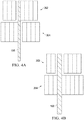
- FIG. 4A and FIG. 4B are simplified illustrations of how beams may be collimated with an exemplary double-stacked MLC system.
- the leaves in the first MLC 302 and second MLC 304 are offset by one half the width of the leaves, or by approximately one half of the width of the leaves.
- the leaves in first MLC 302 and second MLC 304 can be moved independently of one another.
- one leaf in first MLC 302 and one leaf in second MLC 304 can be retracted to create the smallest aperture through which beam 106 may pass (in the dimension corresponding to the width of the leaves).
- the leaves of the MLCs are offset in a manner to allow for collimation of a beam thinner than the widths of the leaves of each of the first and second multileaf collimators.
- the width of such a beam may be 4.15 mm when the width of the leaves in both first MLC 302 and second MLC 304 are approximately 8.3 mm.
- FIG. 4B shows that when two leaves of one of the MLCs are retracted and an overlapping leaf in the other MLC is retracted, the second smallest aperture through which radiation beam 106 may pass is created, for example, a beam having a width of 8.3 mm.
- the MLCs are stacked, the leaves in each MLC are approximately the same width, and the leaves in first MLC 302 are offset from the leaves in second MLC 304 by approximately one-half of their width (as shown in FIG. 4 ).
- the MLC leaves in such an implementation may be designed to be approximately twice the width of a typical MLC, while still achieving approximately the same resolution. For example, to achieve a 5mm resolution at isocenter, a typical single MLC will require leaves approximately 2.5mm wide, while in a double-stacked design with offset, the leaves may be approximately 5 mm wide and achieve the same resolution. Such a design may be desirable for ease of machining and to provide more material for equipment connecting to or interfacing with the leaves.
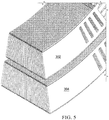
- FIG. 5 is an isometric view of the exemplary collimating system of FIG. 3 showing double stacked MLCs 302 and 304.
- the exemplary collimating system includes multiple MLCs, arranged to have an additive beam attenuating affect, the leaves in each of the individual MLCs may have a decreased height, or thickness, compared to the leaves in a standard single MLC collimating system.
- the leaves in each MLC may be approximately one half the height of the leaves in a typical single MLC made of the same material. Such may decrease the weight of individual leaves, making them easier to control and allowing for more rapid movement, which can reduce overall treatment time.
- the collimators are designed to be focused or double focused (as preferred, and described further below), the edges of the MLCs exposed to the beam will have greater attenuation and the leaves of each of the MLCs may be further decreased in height.
- first MLC 302 and second MLC 304 utilize leaf heights for first MLC 302 and second MLC 304 that are the same, or approximately the same. Because both the first MLC 302 and second MLC 304 are responsible for shaping radiation beam 106, both first MLC 302 and second MLC 304 are each preferably designed with leaf heights sufficient to fully attenuate the radiation beam 106, as an example, for medical radiation therapy.
- the leaves of both first MLC 302 and second MLC 304 are made with a tungsten alloy of 17.5 gm/cc or higher density (e.g., 5:5:90 Cu:Ni:W) and are each approximately 5.5 cm thick.
- a preferred exemplary collimating system may include 34 leaves in each bank of the first MLC 302, and 35 leaves in each bank of the second MLC 304, although different resolutions and numbers of leaves in each bank are contemplated.
- the MLCs used with the technology of the present disclosure be double focused, as shown in the drawings (as opposed to using non-focused collimators such as those having linear leaf motion and rounded leaf ends).
- MLCs are double focused when all of the beam defining surfaces of the leaves project back to the radiation source.
- radiation beam 106 fans out from radiation source 104.
- the exemplary collimating systems utilize curved leaves that retract along an arc (e.g., as shown in FIGS. 1 , 3 ), the edges of the leaves, as they retract, always represent a line projecting back to radiation source 104. With such a design, the entire thickness of the leaves will attenuate beam 106 as it passes through the collimating device, providing for a sharper beam edge with low penumbra regardless of how far the leaves are retracted.
- FIG. 5 illustrates a manner by which the MLCs may focus beam 106 in the other dimension - by virtue of the leaves' width increasing with distance from radiation source 104.
- the width of the leaves at the top of MLC 302 is the thinnest. The width is larger at the bottom of the leaves of MLC 302, larger still at the top of the leaves in second MLC 304, and largest at the bottom of the leaves in MLC 304. This design is also illustrated in FIG. 6 .
- the focusing of the leaf designs is purposefully defocused slightly.
- the leaf surfaces may designed to project to a point one to two centimeters above or below the actual radiation source. This slight defocusing can significantly decrease radiation leakage through the space between the leaves (i.e., interleaf gaps), while having only a small impact on beam penumbra.
- first MLC 302 and second MLC 304 have different focus points.
- the arcs on which the MLCs travel would therefore intersect at some point but within their boundaries they can be designed to have sufficient clearance from one another.
- the differing focus points may be chosen to improve the match of penumbra between the first multileaf collimator and the second multileaf collimator even though they are at different distances from the source.
- the focus of the first MLC can be placed at the effective source point and the focus of the second MLC can be moved off of the effective source point.
- Such an exemplary design would increase the penumbra of the lower MLC to better match the penumbra of the upper MLC and provide better dosimetric matching of the beam edges shaped by first MLC and second MLC.
- collimator jaws are necessary to prevent radiation leakage outside of beam apertures.
- the rounded leaf ends of a conventional MLC are poor at blocking radiation even when completely closed, closed leaf ends are often moved to a position where they are blocked by the conventional collimator jaws.
- the utilization of double focused leaves limits leaf end leakage and penumbra to an extent that an adjacent, stacked MLC of reasonable thickness (having an offset leaf-meeting location) will be sufficient to block transmission so that conventional collimator jaws are not necessary.
- the present disclosure thus contemplates collimating systems that do not include collimator jaws.
- a preferred implementation of the present disclosure includes leaf designs with approximately the same width in the first MLC 302 as in the second MLC 304.
- approximately the same width means that the bottom width of the leaves in first MLC 302 is approximately the same (i.e., just slightly smaller) than the top width of the leaves in second MLC 304.
- focused leaves in the first and second MLCs can be thought of as having approximately the same width - including a small additional width being added along the leaves as they extend further from radiation source 104, as is necessary to provide a focused design (e.g., as shown in FIGS. 5 and 6 ).
- first MLC 302 and second MLC 304 are approximately the same
- present disclosure contemplate designs where the leaf widths can be different between the stacked MLCs.
- first MLC 302 are immediately adjacent to each other or touching
- second MLC 304 are immediately adjacent to one another or touching.
- the gaps between adjacent leaves in both first MLC 302 and second MLC 304 are minimized in a manner that will minimize radiation leakage between the leaves, yet still allow for relative motion. This type of implementation is illustrated in, for example, FIGS. 4 , 5 , and 6 .
- the leaves of an MLC are able to move independently, there is necessarily a small gap between them through which some radiation may pass.
- the collimating system of the present disclosure contemplates that the leaves of first MLC 302 and the leaves of second MLC 304 are preferably arranged so the gaps between leaves are not aligned so radiation beam 106 may not transmit through a leaf gap in first MLC 302 and then directly through a leaf gap in second MLC 304.
- the leaves of first MLC 302 are preferably offset from the leaves of second MLC 304 so that there is no straight-line path for the beam to travel through the inter-leaf gaps of both of MLCs. See, for example, FIGS. 4 , 5 and 6 .
- first MLC 302 and second MLC 304 are offset by approximately 50% of their width so as to provide the greatest separation between the inter-leaf gaps of the first MLC 302 and the second MLC 304. Offsets of less than 50% of the leaf width are contemplated by the present disclosure but an offset is preferably utilized and is preferably is greater than 10% of the width of the leaves.
- inter-leaf leakage must be prevented through complex machining of the leaves in the location where they mate or abut one another.
- tongue and groove or stepped designs may be employed to interrupt an otherwise linear inter-leaf gap that could allow significant beam leakage.
- the collimating system of the present disclosure contemplates the ability to eliminate such additional machining because, even if straight-edged leaves are utilized, the leakage path through the collimating system will be in interrupted by virtue of the previously described overlap or offset of the leaves between first MLC 302 and second MLC 304.
- a preferred implementation includes simple, straight-edged leaves without additional machining or features to block interleaf leakage. Such a design may also result in a more uniform leaf edge and decreased beam penumbra.
- the mating surfaces of the leaves may be machined to further decrease the leakage paths and enable reduction of the height of the MLCs. Any configuration of nonlinear surfaces may prove beneficial, such as a tongue and groove design, or the like.
- steps are machined into the mating surfaces of the leaves.
- FIG. 7 shows a first partial leaf bank 702, corresponding to first MLC 302 and second partial leaf bank 706, corresponding to second MLC 304.
- the leaves have a width 709 and heights 704 and 708.
- leaf height 704 of partial leaf bank 702 and leaf height 708 of partial leaf bank 706 are the same and are approximately 5.5 cm. It is not necessary, however, for the height of each of the leaf banks to be the same.
- the exemplary leaf mating surface machining depicted in FIG. 7 is a step feature, included in the leaves of both the first MLC 302 and second MLC 304.
- height 704 and height 708 are the same, and both equal to the variable "H".
- transmission paths such as path 710, where the incident radiation beam 106 must travel through the full height 704 of leaf bank 702, and the full height 708 of leaf bank 706, exhibiting maximum beam attenuation through a thickness of 2 x H.
- the step feature thus allows for a 33% reduction in the total height of the leaves in MLC 302 and MLC 304 to achieve the same attenuation observed by MLCs without the step feature.
- Such a feature may therefore be used to reduce the amount of material required and the weight of the leaves, thereby improving MLC speed and performance.
- the leaf height for each of the MLCs 302 304 may be approximately 3.7 cm.
- the leaf offset will result in beam 106 being attenuated by only about half of the typical amount of material at locations at the edge of aperture 212. Or, if a step feature is utilized, radiation beam 106 will be attenuated by even less material (see, for example, path 716 in FIG. 7 ).
- the exemplary MLC assemblies discussed herein may also include mechanical structures for supporting and driving the leaves, servomotors for manipulating the position of the leaves, and control systems for achieving the desired beam shape and attenuation.
- FIG. 8 is a further depiction of the exemplary collimating system, with the inclusion of drive linkages 802 and leaf drive motor assemblies 804.
- a number of other related systems such as control systems, encoders, power cables, etc., are not depicted but may also be included.
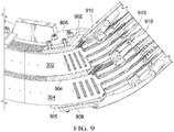
- FIG. 9 depicts additional structures for supporting and driving the leaves of an exemplary collimating system including a top leaf support guide 902, a middle leaf support guide 904, and a bottom leaf support guide 906.
- the leaves include tabs at their top and bottom surfaces, which may ride within grooves in the leaf support guides (see, e.g., FIG. 6 ).
- guide pressure adjustment plates 908 may also be included to ensure smooth, but not loose, movement of the leaves.
- One particular implementation may also include rods 910 to further guide movement of the leaves and avoid excessive rocking.
- one implementation for the design of a leaf assembly 1002 utilizes a frame 1004, separate from attenuating material 1006.
- the frame 1004 portion of leaf assembly 1002 that will engage with leaf support guides can be made with a material different from that of attenuating material 1006.
- the attenuating material 1006 is typically a tungsten alloy or other high density material for radiation attenuation
- the frame 1004 may be made from another material, for example, stainless steel.
- Attenuating material 1006 may be designed to be an insert into frame 1004 and the two materials may be fixed together using a number of methods such as bonding, sintering or welding.
- frame 1004 does not extend all the way to the attenuating edge 1008 of leaf assembly 1002 to avoid variation in the overall attenuating properties of the leaf assembly 1002.
- an exemplary radiation therapy device 101 may utilize a gantry 112 carrying a radiation source 104 capable of emitting a radiation beam 106.
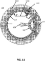
- FIG. 11 depicts an implementation of radiation therapy device 101 where the radiation source 104 is a linear accelerator and the linear accelerator is divided into components 1102 spaced around gantry 112.
- the radiation source 104 is a linear accelerator and the linear accelerator is divided into components 1102 spaced around gantry 112.
- Such a configuration may utilize RF waveguides 1104 between the linac components 1102 and can result in an overall decrease to the maximum diameter of radiation therapy device 101.
- multiple radiation sources may be included around gantry 112.
- An exemplary gantry 112 is as compact as possible while having a large bore, for example, the bore may be designed to be greater than 80 cm. In one implementation the bore is 110 cm.
- the gantry is a ring gantry, which carries at least one radiation therapy beam source and is used to reorient the beam source during therapy in a manner allowing for the delivery of coplanar beams. It is contemplated that the gantry not necessarily need to be purely in the shape of a ring. Gantries that deviate from a circular shape, or that even incorporate break(s) in their structure are contemplated.
- the radiation therapy devices discussed herein may utilize any of the beneficial collimating device embodiments and concepts described above. Such devices will have very little transmission, low-penumbra beams, and be capable of delivering high-quality treatment plans.
- the present disclosure defines radiation therapy systems that are configured to deliver only coplanar radiation therapy.
- a ring gantry as depicted in FIGS. 1 and 11 is applicable to co-planar radiation therapy.
- the patient couch is not configured to rotate and the radiation therapy device is not cantilevered, yet the system can nevertheless deliver high-quality treatment plans.
- the term cantilevered, as used herein, refers to the inclusion of an arm or other structure to extend the location where the radiation beam emits from the device out away from the main rotating structure.
- Such cantilevered devices are typically used with couches that rotate to enable non-coplanar therapy to a patient from a beam source that only moves within a given plane.
- the location where the radiation beam is emitted must be extended substantially, e.g., for the purpose of allowing a couch to rotate and enable the delivery of non-coplanar beams.
- a radiation therapy device where the beam emission location is extended only a minor distance not sufficient for the enablement of non-coplanar therapy, is not considered cantilevered.
- Embodiments of the radiation therapy devices disclosed herein may be used to perform arc therapy (also called VMAT), where the radiation therapy beam source emits a radiation beam while the source is moving (e.g., during rotation of a gantry).
- VMAT arc therapy
- certain beneficial embodiments utilizing the collimating device concepts discussed above may be designed so that the radiation therapy device is not configured to deliver arc therapy, but can nevertheless deliver high-quality treatment plans in a short period of time.
- Diagnostic-quality CT scanners are typically continuously rotating CT systems, based on 'slip-ring technology' with single or multi-slice detector capabilities and capable of axial or helical data acquisition and image reconstruction. They can have multiple sources and detector arrays configured to acquire many tens to hundreds of image slices. They are often employed in diagnostic X-Ray departments of a hospital or clinic and typically utilize kilovoltage energy X-Rays in a fan beam geometry that rotates around the patient. Diagnostic quality CT scanners are often employed to acquire high quality CT imaging for use in the treatment planning of radiation therapy patients. The high quality CT images allow for the calibration of Hounsfield numbers to tissue density for improved dose computation.
- Diagnostic quality CT scanners are distinct from cone beam CT systems that may employ a retractable X-Ray tube and flat panel imager to create cone beam X-Ray CT.
- the CT imaging data produced by a cone beam CT suffers from poorer image quality than standard CT units, lower soft tissue contrast, organ motion artifacts, and Hounsfield numbers that do not accurately reflect the electron density of the imaged tissues.
- Diagnostic-quality CT scanners are also distinct from megavoltage systems that may use the megavoltage radiation therapy beam as an imaging source, with a flat panel imager, to produce megavoltage CT images that also lead to poor quality noisy images with low soft tissue contrast.
- diagnostic-quality CT scanners utilized herein will have a large bore (e.g., 70-90 cm).
- the diagnostic-quality CT scanner may be an "off-the-shelf' unit designed for radiation therapy simulation, including a couch compatible with radiation therapy and therapy immobilization equipment.
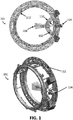
- a scanner 1201 is depicted in FIG. 12 .
- the diagnostic-quality CT scanner may be a PET/CT scanner with a CT scanner adjacent a Positron Emission Tomography (PET) scanner.
- PET Positron Emission Tomography
- a diagnostic-quality CT scanner may be placed adjacent to any of the radiation therapy devices discussed herein for the beneficial uses discussed below.
- the CT scanner 1201 may be placed adjacent a radiation therapy device 101 utilizing a ring gantry, as previously discussed herein. "Adjacent" simply means in close proximity, and contemplates the devices touching, being separated slightly, or being integrated together.
- the CT and radiation therapy devices are, however, intended to have separate gantries in the preferred implementation.
- the diagnostic-quality CT scanner has an imaging isocenter and the radiation therapy device has a radiation therapy isocenter that is separate from the imaging isocenter.
- Separate is understood to mean that the isocenters are a significant distance apart, for example, such that a couch must move the patient between imaging and treatment.
- the isocenters are approximately 80 cm away from one another.
- the CT scanner and radiation therapy device are fixed in position relative to one another, and also relative to the treatment room, meaning that they are mounted in a way that they cannot be moved (as if, for example, they were on rails, or a turntable).
- CT and RT systems in FIG. 13 are shown arranged so the couch first enters the CT, and then the RT device, it is contemplated that the arrangement could be reversed.
- the CT system and RT system are generally lined up with one another so that a couch can translate a patient in one direction to move from one system to the other.
- the RT system includes a gantry having a bore (e.g., a ring gantry)
- the bores of the CT and RT system are generally aligned.
- this may be accomplished by raising the CT system on a platform or by lowering the RT system through use of a pit in the floor of the treatment room (see illustration in FIG. 15 of an RT system 101 viewed from the end, showing the system's bore and a pit 1504 in the floor; the pit can also be seen in FIG. 14 ).
- the combined CT/RT system may utilize a couch configured to position the patient both for imaging and for radiation therapy by translating the patient between the diagnostic quality CT scanner and the radiation therapy device.
- a couch may be specially designed for the combined CT/RT system.
- the couch would be designed to move up and down, and to translate through the bore(s) of the system, but may be configured to not rotate, as discussed above.
- an off-the-shelf CT simulator couch may be used and positioned as close as possible to the CT/RT system so it can extend through both isocenters.
- an off-the-shelf PET/CT scanner couch can be used, as it is designed for use in a multiple iso-center system.
- off-the-shelf' system refers to a system that can be purchased in a configuration ready to be used, or used with only minor modifications.
- the combined system may be configured to deliver only co-planar radiation therapy.
- the radiation beam source may only travel within a plane (e.g., on a ring gantry), the RT device may not be cantilevered, and the RT/CT couch may not be configured to rotate.
- the combined CT/RT system has the ability to acquire diagnostic-quality CT images of a patient on the treatment couch, just prior to radiation therapy, which can provide a number of benefits.
- the patient will be positioned in exactly the same manner for pre-treatment imaging and for the treatment itself, thereby reducing treatment errors that may occur when a patient's body is positioned or supported in a different way between imaging and treatment.
- the system can be configured to reoptimize treatment plans and perform on-table adaptive therapy based on its diagnostic-quality CT imaging.
- the treatment couch can move the patient into position for CT imaging. Because the imaging received is diagnostic quality, the system can effectively apply deformable image registration to morph the original treatment plan onto the current CT. The system can then allow for autocontoring of the tissues and targets that were segmented in the original plan onto the current CT scan. The CT numbers on the current scan can be converted to electron densities to compute an accurate dose delivery prediction before treating the patient. The quality of the dose distribution for the current plan may then be assessed and, if the plan is suboptimal (e.g., dose to the tumor/target too low or dose to critical structures too high), the treatment plan can be reoptimized to improve the dose distribution on the spot. The couch may then move the patient toward the RT isocenter for treatment.
- the plan is suboptimal (e.g., dose to the tumor/target too low or dose to critical structures too high)
- the treatment plan can be reoptimized to improve the dose distribution on the spot.
- the couch may then move the patient toward the RT isocenter for treatment.
- the system is capable of adapting to conditions relating to the patient or patient setup that may have changed since the time the original treatment plan was created and to deliver an improved plan.
- Such adaptive treatment / reoptimization can significantly improve dose distributions and patient outcomes.
- the system can be configured to utilize diagnostic-quality CT images to reoptimize a treatment plan, and may be configured to do so just prior to treatment, while the patient is on the couch.
- control systems and software can thus include, but are not limited to, CT image acquisition, deformable image registration, automatic tissue segmentation/contouring, dose computation, treatment plan optimization and radiation therapy delivery.
- FIG. 14 includes additional views of an exemplary arrangement for a combination CT/RT system.
- RF shielding may be included in certain embodiments of the CT/RT systems disclosed herein.
- the radiation therapy beam source is a linear accelerator
- RF radiation from various linac components may interfere with devices in the room, or in the patient (such as pacemakers, ICDs, etc.).
- One manner for reducing interference is to utilize RF shielding in containers for linac components 1102. Examples of such containers can be seen in FIG. 14 and are discussed in detail in U.S. Patents 8,836,332 and 9,446,263 to the current assignee.
- Embodiments of the combined CT/RT systems may also include radiation shielding for components of the CT scanner, to prevent damage to scanner components caused by the scatter of megavoltage radiation from the radiation therapy beam source.
- One implementation may utilize a shield between the diagnostic-quality CT scanner and the radiation therapy device.
- Another implementation may form fit and cover or replace the outer shroud of the CT scanner facing toward the radiation therapy unit with a high atomic number material to absorb or scatter radiation away from the unprotected components of the X-Ray CT scanner.
- the shielding material may be a few centimeters of lead or a single centimeter of tungsten.
- the chosen treatment couch may have limited degrees of freedom.
- the couch may only be able to translate up and down, and in and out of the bore (as is the case with typical off-the-shelf CT systems).
- Such a lack of lateral movement may cause issues with positioning a patient for radiation treatment if the target is located lateral from the patient's longitudinal axis or away from the midsaggital plane.
- a number of designs can overcome this limitation.
- an off-the-shelf CT couch can be mounted on a platform capable of lateral movement.
- a couch could be altered or redesigned to include the additional degree of freedom. In the embodiment depicted in FIG.
- the radiation therapy device 101 (depicted here inside of optional pit 1504) may be configured to itself be shifted to move laterally with respect to the couch and the patient located within its bore.
- the gantry may be configured to be translated orthogonally to couch motion over a range of at least 8 cm to facilitate the positioning of the radiation therapy isocenter in the patient before treatment
- the radiation therapy devices described herein may also be configured for use with an MRI, as described in a number of additional patents and applications assigned to the assignee of the present disclosure (e.g., U.S. Patent No. 9,446,263 ).
- Figure 16 shows an example of such a configuration, utilizing a split MRI design with magnet halves 1602 and 1604 that surround radiation therapy device 101 and are connected by buttresses 1606.
- the system may be designed to be installed with either MRI guidance or X-Ray CT guidance and may also be designed to facilitate conversion between the different types of guidance through a versatile base plate or multiple versatile base plates (see, e.g., FIG. 16 ).
- the base plate(s) cover at least a portion of the area under the system sufficient for rigidly mounting and aligning it.
- the base plate(s) may be designed with a number of drill patterns to accept, for example, 1) the RT device, 2) a CT scanner or an MRI, and 3) a CT couch, PET/CT couch or MRI couch.
- a system could be converted from CT guidance to MRI guidance without removing or disturbing the radiation therapy device itself.
- control systems for multileaf collimators can be realized in digital electronic circuitry, integrated circuitry, specially designed application specific integrated circuits (ASICs), field programmable gate arrays (FPGAs) computer hardware, firmware, software, and/or combinations thereof.
- ASICs application specific integrated circuits
- FPGAs field programmable gate arrays
- These various aspects or features can include implementation in one or more computer programs that are executable and/or interpretable on a programmable system including at least one programmable processor, which can be special or general purpose, coupled to receive data and instructions from, and to transmit data and instructions to, a storage system, at least one input device, and at least one output device.
- the programmable system or computing system may include clients and servers.
- a client and server are generally remote from each other and typically interact through a communication network. The relationship of client and server arises by virtue of computer programs running on the respective computers and having a client-server relationship to each other.
- machine-readable signal refers to any signal used to provide machine instructions and/or data to a programmable processor.
- the machine-readable medium can store such machine instructions non-transitorily, such as for example as would anon-transient solid-state memory or a magnetic hard drive or any equivalent storage medium.
- the machine-readable medium can alternatively or additionally store such machine instructions in a transient manner, such as for example as would a processor cache or other random access memory associated with one or more physical processor cores.
- one or more aspects or features of the subject matter described herein can be implemented on a computer having a display device, such as for example a cathode ray tube (CRT) or a liquid crystal display (LCD) or a light emitting diode (LED) monitor for displaying information to the user and a keyboard and a pointing device, such as for example a mouse or a trackball, by which the user may provide input to the computer.
- a display device such as for example a cathode ray tube (CRT) or a liquid crystal display (LCD) or a light emitting diode (LED) monitor for displaying information to the user
- LCD liquid crystal display
- LED light emitting diode
- a keyboard and a pointing device such as for example a mouse or a trackball
- feedback provided to the user can be any form of sensory feedback, such as for example visual feedback, auditory feedback, or tactile feedback; and input from the user may be received in any form, including, but not limited to, acoustic, speech, or tactile input.
- Other possible input devices include, but are not limited to, touch screens or other touch-sensitive devices such as single or multi-point resistive or capacitive trackpads, voice recognition hardware and software, optical scanners, optical pointers, digital image capture devices and associated interpretation software, and the like.
- phrases such as "at least one of' or “one or more of” may occur followed by a conjunctive list of elements or features.
- the term “and/or” may also occur in a list of two or more elements or features. Unless otherwise implicitly or explicitly contradicted by the context in which it used, such a phrase is intended to mean any of the listed elements or features individually or any of the recited elements or features in combination with any of the other recited elements or features.
- the phrases “at least one of A and B;” “one or more of A and B;” and “A and/or B” are each intended to mean "A alone, B alone, or A and B together.”
- a similar interpretation is also intended for lists including three or more items.
- phrases “at least one of A, B, and C;” “one or more of A, B, and C;” and “A, B, and/or C” are each intended to mean “A alone, B alone, C alone, A and B together, A and C together, B and C together, or A and B and C together.”
- Use of the term “based on,” above and in the claims is intended to mean, “based at least in part on,” such that an unrecited feature or element is also permissible.
Landscapes
- Health & Medical Sciences (AREA)
- Engineering & Computer Science (AREA)
- Life Sciences & Earth Sciences (AREA)
- Biomedical Technology (AREA)
- Nuclear Medicine, Radiotherapy & Molecular Imaging (AREA)
- Pathology (AREA)
- Radiology & Medical Imaging (AREA)
- Animal Behavior & Ethology (AREA)
- General Health & Medical Sciences (AREA)
- Public Health (AREA)
- Veterinary Medicine (AREA)
- Medical Informatics (AREA)
- Physics & Mathematics (AREA)
- High Energy & Nuclear Physics (AREA)
- Heart & Thoracic Surgery (AREA)
- Biophysics (AREA)
- Molecular Biology (AREA)
- Surgery (AREA)
- Optics & Photonics (AREA)
- Pulmonology (AREA)
- Theoretical Computer Science (AREA)
- Spectroscopy & Molecular Physics (AREA)
- General Engineering & Computer Science (AREA)
- Radiation-Therapy Devices (AREA)
- Apparatus For Radiation Diagnosis (AREA)
Claims (15)
- Système comprenant :un tomodensitomètre de qualité diagnostique (1201) destiné à prendre des clichés d'un patient, le tomodensitomètre de qualité diagnostique ayant un isocentre d'imagerie ;un dispositif de radiothérapie (101) placé à côté du tomodensitomètre de qualité diagnostique, le dispositif de radiothérapie comprenant un portique annulaire portant une source de faisceaux de radiothérapie et ayant un isocentre de radiothérapie séparé de l'isocentre d'imagerie du tomodensitomètre de qualité diagnostique, ledit dispositif de radiothérapie n'étant pas en porte-à-faux ; etune table conçue pour positionner le patient en vue de la prise de clichés et de la radiothérapie, par translation du patient entre le tomodensitomètre de qualité diagnostique et le dispositif de radiothérapie ;ledit système étant conçu pour délivrer uniquement une radiothérapie coplanaire.
- Système selon la revendication 1, dans lequel le portique annulaire est conçu pour déplacer la source uniquement vers différentes positions dans un plan.
- Système selon la revendication 1, dans lequel la table n'est pas conçue pour pivoter.
- Système selon la revendication 1, dans lequel la source de faisceaux de radiothérapie est un accélérateur linéaire et l'accélérateur linéaire est divisé en composants espacés autour du portique annulaire et exploite au moins un guide d'ondes RF entre les composants de l'accélérateur linéaire.
- Système selon la revendication 1, dans lequel le tomodensitomètre de qualité diagnostique est conçu pour la simulation RT.
- Système selon la revendication 1, dans lequel le tomodensitomètre de qualité diagnostique est un appareil de tomographie par émission de positrons/tomodensitométrie.
- Système selon la revendication 1, dans lequel le système comprend en outre un système de commande conçu pour exploiter des images de tomographie de qualité diagnostique pour réoptimiser un plan de traitement.
- Système selon la revendication 7, dans lequel la réoptimisation est effectuée juste avant le traitement, alors que le patient est allongé sur la table.
- Système selon la revendication 1, dans lequel le portique annulaire est conçu pour subir un mouvement de translation orthogonalement au déplacement de la table.
- Système selon la revendication 11, dans lequel le portique est conçu pour subir un mouvement de translation sur une plage d'au moins 8 cm afin de faciliter le positionnement de l'isocentre de radiothérapie chez le patient avant le traitement.
- Système selon la revendication 1, comprenant en outre un blindage contre les radiations entre l'appareil de radiothérapie et le tomodensitomètre de qualité diagnostique.
- Système selon la revendication 11, dans lequel le blindage contre les rayonnements comprend un matériau à numéro atomique élevé qui recouvre ou remplace une partie d'une enveloppe extérieure du tomodensitomètre de qualité diagnostique faisant face à l'appareil de radiothérapie.
- Système selon la revendication 1, dans lequel l'appareil de radiothérapie est un accélérateur linéaire et le système comprend en outre un blindage RF pour au moins un composant de l'accélérateur linéaire.
- Système selon la revendication 1, comprenant en outre au moins une plaque de base polyvalente conçue pour le montage d'au moins un système choisi dans un groupe comprenant un appareil de radiothérapie, un tomodensitomètre, un appareil d'IRM, une table de tomographie, une table de tomographie par émission de positrons/tomodensitométrie et une table d'IRM.
- Système selon la revendication 14, dans lequel l'au moins une plaque de base polyvalente permet de faire passer le système entre un guidage par tomographie et un guidage par IRM sans retirer l'appareil de radiothérapie.
Priority Applications (2)
| Application Number | Priority Date | Filing Date | Title |
|---|---|---|---|
| EP23209870.7A EP4338677A3 (fr) | 2016-12-13 | 2017-12-13 | Systèmes et procédés de radiothérapie |
| EP21151955.8A EP3827883B1 (fr) | 2016-12-13 | 2017-12-13 | Systèmes de radiothérapie |
Applications Claiming Priority (2)
| Application Number | Priority Date | Filing Date | Title |
|---|---|---|---|
| US201662433745P | 2016-12-13 | 2016-12-13 | |
| PCT/US2017/066182 WO2018112085A1 (fr) | 2016-12-13 | 2017-12-13 | Systèmes et procédés de radiothérapie |
Related Child Applications (2)
| Application Number | Title | Priority Date | Filing Date |
|---|---|---|---|
| EP23209870.7A Division EP4338677A3 (fr) | 2016-12-13 | 2017-12-13 | Systèmes et procédés de radiothérapie |
| EP21151955.8A Division EP3827883B1 (fr) | 2016-12-13 | 2017-12-13 | Systèmes de radiothérapie |
Publications (2)
| Publication Number | Publication Date |
|---|---|
| EP3554635A1 EP3554635A1 (fr) | 2019-10-23 |
| EP3554635B1 true EP3554635B1 (fr) | 2021-01-20 |
Family
ID=60857192
Family Applications (3)
| Application Number | Title | Priority Date | Filing Date |
|---|---|---|---|
| EP23209870.7A Pending EP4338677A3 (fr) | 2016-12-13 | 2017-12-13 | Systèmes et procédés de radiothérapie |
| EP21151955.8A Active EP3827883B1 (fr) | 2016-12-13 | 2017-12-13 | Systèmes de radiothérapie |
| EP17822532.2A Not-in-force EP3554635B1 (fr) | 2016-12-13 | 2017-12-13 | Systèmes de radiothérapie |
Family Applications Before (2)
| Application Number | Title | Priority Date | Filing Date |
|---|---|---|---|
| EP23209870.7A Pending EP4338677A3 (fr) | 2016-12-13 | 2017-12-13 | Systèmes et procédés de radiothérapie |
| EP21151955.8A Active EP3827883B1 (fr) | 2016-12-13 | 2017-12-13 | Systèmes de radiothérapie |
Country Status (10)
| Country | Link |
|---|---|
| US (3) | US11000706B2 (fr) |
| EP (3) | EP4338677A3 (fr) |
| JP (3) | JP2020501662A (fr) |
| KR (1) | KR20190092530A (fr) |
| CN (2) | CN110382049A (fr) |
| AU (1) | AU2017378315A1 (fr) |
| BR (1) | BR112019012061A2 (fr) |
| CA (1) | CA3046091A1 (fr) |
| RU (1) | RU2019121943A (fr) |
| WO (1) | WO2018112085A1 (fr) |
Families Citing this family (27)
| Publication number | Priority date | Publication date | Assignee | Title |
|---|---|---|---|---|
| EP4325235A3 (fr) | 2015-02-11 | 2024-05-22 | ViewRay Technologies, Inc. | Planification et commande pour radiothérapie guidée par résonance magnétique |
| US10398911B2 (en) * | 2015-09-25 | 2019-09-03 | Varian Medical Systems Internationl AG | Method and apparatus for using a multi-layer multi-leaf collimation system |
| RU2019121943A (ru) | 2016-12-13 | 2021-01-15 | Вьюрэй Текнолоджиз, Инк. | Системы и способы лучевой терапии |
| AU2018333280B2 (en) * | 2017-09-14 | 2024-08-29 | Australian Nuclear Science And Technology Organisation | An irradiation method and system |
| US10500417B2 (en) * | 2018-02-05 | 2019-12-10 | Varian Medical Systems International Ag | Compensating for leakage radiation in MLC modulated treatment |
| CN109464753B (zh) * | 2018-10-12 | 2020-10-27 | 高飞 | 放射治疗仪的放射束引导机构 |
| US10892064B2 (en) * | 2018-12-05 | 2021-01-12 | Shanghai United Imaging Healthcare Co., Ltd. | Multi-leaf collimator |
| WO2021007459A1 (fr) * | 2019-07-10 | 2021-01-14 | Sun Nuclear Corporation | Assurance qualité de radiothérapie fondée sur un scintillateur |
| WO2021016757A1 (fr) | 2019-07-26 | 2021-02-04 | Shanghai United Imaging Healthcare Co., Ltd. | Système de radiothérapie et son procédé de mise en œuvre |
| KR102314902B1 (ko) * | 2019-08-20 | 2021-10-21 | 한국원자력의학원 | 진단용 방사선 장치에 장착 가능한 선량 조절 장치 및 이를 포함하는 선량 조절 시스템 |
| US12257456B2 (en) * | 2019-11-25 | 2025-03-25 | The Regents Of The University Of California | Systems and methods for dynamic control of radiation dose in radiation therapy |
| GB2594446B (en) | 2020-03-13 | 2022-06-08 | Elekta ltd | Multi-leaf collimator module |
| GB2592987A (en) * | 2020-03-13 | 2021-09-15 | Elekta ltd | Leaf for a multi-leaf collimator |
| EP4117776A1 (fr) | 2020-03-13 | 2023-01-18 | Elekta Limited | Collimateur multilame |
| GB2592984B (en) | 2020-03-13 | 2022-06-22 | Elekta ltd | Leaf drive mount for a multi-leaf collimator |
| GB2592990B (en) | 2020-03-13 | 2022-03-16 | Elekta ltd | Leaf actuator for a multi-leaf collimator |
| US11511130B2 (en) * | 2020-04-15 | 2022-11-29 | Shanghai United Imaging Healthcare Co., Ltd. | Systems and methods for adjusting multi-leaf collimator |
| CN111681736B (zh) * | 2020-06-08 | 2023-05-12 | 苏州雷泰医疗科技有限公司 | 一种基于分象限的正交双层光栅动态调强分割方法 |
| US11712583B2 (en) * | 2020-06-30 | 2023-08-01 | Accuray Incorporated | Utilizing an offset multi-leaf collimator to improve dose conformality and homogeneity |
| US11344749B2 (en) | 2020-10-16 | 2022-05-31 | Varian Medical Systems, Inc. | Magnetoresistive linear position detection in a radiation therapy system |
| US11692851B2 (en) * | 2020-10-16 | 2023-07-04 | Varian Medical Systems, Inc. | Magnetoresistive rotational position detection in a radiation therapy system |
| CN113797454A (zh) * | 2021-09-29 | 2021-12-17 | 翰斯泰医疗科技(苏州)有限公司 | 一种ct影像引导的放射治疗设备 |
| US11904186B2 (en) * | 2022-01-12 | 2024-02-20 | Capital Medical University | Radiotherapeutical or radiosurgical system comprising two or more rotatable high-intensity radiation sources and a ring-shaped imager, and methods thereof |
| KR102702633B1 (ko) | 2022-05-23 | 2024-09-04 | 강원대학교병원 | 의료용 방사선 차폐 장치 |
| US12201850B2 (en) | 2022-06-16 | 2025-01-21 | Sun Nuclear Corporation | High dose rate radiation therapy systems and dosimetry |
| JP2024064144A (ja) * | 2022-10-27 | 2024-05-14 | 株式会社日立製作所 | 放射線治療装置 |
| US12544596B2 (en) | 2023-03-30 | 2026-02-10 | Sun Nuclear Corporation | Adjustable radiation detector support |
Family Cites Families (383)
| Publication number | Priority date | Publication date | Assignee | Title |
|---|---|---|---|---|
| GB1014630A (en) | 1964-11-06 | 1965-12-31 | Mullard Ltd | Improvements in and relating to adjustable couches |
| US4233662A (en) | 1973-04-25 | 1980-11-11 | Emi Limited | Radiography |
| DE2455447C3 (de) | 1974-11-22 | 1981-02-05 | Siemens Ag, 1000 Berlin Und 8000 Muenchen | Patientenlagerungsvorrichtung eines Röntgengerätes |
| US4463266A (en) | 1981-02-20 | 1984-07-31 | Instrument Ab Scanditronix | Neutron collimator |
| DE3121728A1 (de) | 1981-06-01 | 1982-12-16 | Siemens AG, 1000 Berlin und 8000 München | Patienten-lagerungsvorrichtung mit einer drehbaren lagerstatt |
| SE462013B (sv) | 1984-01-26 | 1990-04-30 | Kjell Olov Torgny Lindstroem | Behandlingsbord foer radioterapi av patienter |
| US4672212A (en) | 1985-02-28 | 1987-06-09 | Instrument Ab Scanditronax | Multi leaf collimator |
| US4694837A (en) | 1985-08-09 | 1987-09-22 | Picker International, Inc. | Cardiac and respiratory gated magnetic resonance imaging |
| US4771785A (en) | 1986-07-25 | 1988-09-20 | Resonex, Inc. | Magnetic resonance imaging apparatus and three-axis patient positioning assembly for use therewith |
| US4868843A (en) | 1986-09-10 | 1989-09-19 | Varian Associates, Inc. | Multileaf collimator and compensator for radiotherapy machines |
| JPS63294839A (ja) | 1987-05-27 | 1988-12-01 | Nec Corp | 放射線治療用ctシミュレ−タ |
| DE3828639C2 (de) | 1987-08-24 | 1994-08-18 | Mitsubishi Electric Corp | Strahlentherapiegerät |
| US5027818A (en) | 1987-12-03 | 1991-07-02 | University Of Florida | Dosimetric technique for stereotactic radiosurgery same |
| JPH01206300A (ja) | 1988-02-12 | 1989-08-18 | Hitachi Medical Corp | 放射線照射装置用コリメータ |
| EP0371303B1 (fr) * | 1988-11-29 | 1994-04-27 | Varian International AG. | Appareil d'actinothérapie |
| US4851778A (en) | 1988-12-15 | 1989-07-25 | The Regents Of The University Of California | Enhanced S/N MRI for short TR nutation sequences |
| US5117829A (en) | 1989-03-31 | 1992-06-02 | Loma Linda University Medical Center | Patient alignment system and procedure for radiation treatment |
| JPH0767491B2 (ja) | 1989-06-08 | 1995-07-26 | 三菱電機株式会社 | マルチリーフ・コリメータ |
| US5094837A (en) | 1990-01-22 | 1992-03-10 | Wayne State University | Method for use of magnetic resonance imaging to image pancreas using secretin |
| AU652804B2 (en) | 1991-01-19 | 1994-09-08 | Meito Sangyo Kabushiki Kaisha | Composition containing ultrafine particles of magnetic metal oxide |
| US6405072B1 (en) | 1991-01-28 | 2002-06-11 | Sherwood Services Ag | Apparatus and method for determining a location of an anatomical target with reference to a medical apparatus |
| US5166531A (en) | 1991-08-05 | 1992-11-24 | Varian Associates, Inc. | Leaf-end configuration for multileaf collimator |
| JP2735747B2 (ja) | 1991-09-03 | 1998-04-02 | ゼネラル・エレクトリック・カンパニイ | 追跡及びイメージング・システム |
| US5734384A (en) | 1991-11-29 | 1998-03-31 | Picker International, Inc. | Cross-referenced sectioning and reprojection of diagnostic image volumes |
| US5351280A (en) | 1992-03-19 | 1994-09-27 | Wisconsin Alumni Research Foundation | Multi-leaf radiation attenuator for radiation therapy |
| US5317616A (en) | 1992-03-19 | 1994-05-31 | Wisconsin Alumni Research Foundation | Method and apparatus for radiation therapy |
| US5216255A (en) | 1992-03-31 | 1993-06-01 | Siemens Medical Laboratories | Beam profile generator for photon radiation |
| US5332908A (en) | 1992-03-31 | 1994-07-26 | Siemens Medical Laboratories, Inc. | Method for dynamic beam profile generation |
| US5382904A (en) | 1992-04-15 | 1995-01-17 | Houston Advanced Research Center | Structured coil electromagnets for magnetic resonance imaging and method for fabricating the same |
| JPH0654916A (ja) | 1992-08-06 | 1994-03-01 | Mitsubishi Electric Corp | 呼吸モニタ治療方式 |
| US5596619A (en) | 1992-08-21 | 1997-01-21 | Nomos Corporation | Method and apparatus for conformal radiation therapy |
| US5391139A (en) | 1992-09-03 | 1995-02-21 | William Beaumont Hospital | Real time radiation treatment planning system |
| US5647361A (en) | 1992-09-28 | 1997-07-15 | Fonar Corporation | Magnetic resonance imaging method and apparatus for guiding invasive therapy |
| US6005916A (en) | 1992-10-14 | 1999-12-21 | Techniscan, Inc. | Apparatus and method for imaging with wavefields using inverse scattering techniques |
| IT1266276B1 (it) | 1993-02-26 | 1996-12-27 | C A T Di Corsini Giuseppe E C | Tavolo porta-paziente per l'effettuazione di esami medici. |
| US5553618A (en) | 1993-03-12 | 1996-09-10 | Kabushiki Kaisha Toshiba | Method and apparatus for ultrasound medical treatment |
| US5307812A (en) | 1993-03-26 | 1994-05-03 | General Electric Company | Heat surgery system monitored by real-time magnetic resonance profiling |
| JPH08511452A (ja) | 1993-06-09 | 1996-12-03 | ウイスコンシン アラムナイ リサーチ フオンデーシヨン | 抑制された回転自由度を有する放射治療システムおよび動的コリメータ |
| US5373844A (en) | 1993-06-14 | 1994-12-20 | The Regents Of The University Of California | Inverse treatment planning method and apparatus for stereotactic radiosurgery |
| US5547454A (en) | 1993-11-02 | 1996-08-20 | Sandia Corporation | Ion-induced nuclear radiotherapy |
| US5378989A (en) | 1993-11-02 | 1995-01-03 | General Electric Company | Open gradient coils for magnetic resonance imaging |
| US5365927A (en) | 1993-11-02 | 1994-11-22 | General Electric Company | Magnetic resonance imaging system with pointing device |
| US5458125A (en) | 1994-01-28 | 1995-10-17 | Board Of Directors Of The Leland Standford Jr. University | Treatment planning method and apparatus for radiosurgery and radiation therapy |
| US5538494A (en) | 1994-03-17 | 1996-07-23 | Hitachi, Ltd. | Radioactive beam irradiation method and apparatus taking movement of the irradiation area into consideration |
| US5537452A (en) | 1994-05-10 | 1996-07-16 | Shepherd; Joseph S. | Radiation therapy and radiation surgery treatment system and methods of use of same |
| US5602982A (en) | 1994-09-23 | 1997-02-11 | Kelly Properties, Inc. | Universal automated training and testing software system |
| US5443068A (en) | 1994-09-26 | 1995-08-22 | General Electric Company | Mechanical positioner for magnetic resonance guided ultrasound therapy |
| US5513238A (en) | 1994-10-11 | 1996-04-30 | Radionics, Inc. | Automatic planning for radiation dosimetry |
| US5511549A (en) | 1995-02-13 | 1996-04-30 | Loma Linda Medical Center | Normalizing and calibrating therapeutic radiation delivery systems |
| US5555283A (en) | 1995-06-07 | 1996-09-10 | Board Of Regents Of The University Of Texas System | Computer-controlled miniature multileaf collimator |
| US5591983A (en) | 1995-06-30 | 1997-01-07 | Siemens Medical Systems, Inc. | Multiple layer multileaf collimator |
| US6351659B1 (en) | 1995-09-28 | 2002-02-26 | Brainlab Med. Computersysteme Gmbh | Neuro-navigation system |
| DE19639861A1 (de) | 1995-09-28 | 1997-04-10 | Brainlab Med Computersyst Gmbh | Lamellenkollimator für die Strahlentherapie |
| GB9520564D0 (en) | 1995-10-07 | 1995-12-13 | Philips Electronics Nv | Apparatus for treating a patient |
| JPH09154961A (ja) | 1995-12-07 | 1997-06-17 | Toshiba Medical Eng Co Ltd | 放射線治療計画法 |
| US6260005B1 (en) | 1996-03-05 | 2001-07-10 | The Regents Of The University Of California | Falcon: automated optimization method for arbitrary assessment criteria |
| US5602892A (en) | 1996-03-21 | 1997-02-11 | Llacer; Jorge | Method for optimization of radiation therapy planning |
| US5851182A (en) | 1996-09-11 | 1998-12-22 | Sahadevan; Velayudhan | Megavoltage radiation therapy machine combined to diagnostic imaging devices for cost efficient conventional and 3D conformal radiation therapy with on-line Isodose port and diagnostic radiology |
| SE9603535D0 (sv) | 1996-09-27 | 1996-09-27 | Siemens Elema Ab | Undersökningsbord |
| DE69737508T2 (de) | 1996-10-24 | 2007-11-29 | The Nomos Corp. | Methode zur planung und vorrichtung zur planung der bestrahlungsdosierung |
| US5757881A (en) | 1997-01-06 | 1998-05-26 | Siemens Business Communication Systems, Inc. | Redundant field-defining arrays for a radiation system |
| DE19715202B4 (de) | 1997-04-11 | 2006-02-02 | Brainlab Ag | Referenzierungsvorrichtung mit einem Mundstück |
| SE512603C2 (sv) | 1997-06-19 | 2000-04-10 | Elekta Ab | Metod och anordning för automatiserad dosplanering |
| US6052436A (en) | 1997-07-16 | 2000-04-18 | Bionix Development Corporation | Radiation therapy device employing cam pin and cam groove guiding system for controlling movement of linear multi-leaf collimator leaves |
| BE1012534A3 (fr) | 1997-08-04 | 2000-12-05 | Sumitomo Heavy Industries | Systeme de lit pour therapie par irradiation. |
| JP3519248B2 (ja) | 1997-08-08 | 2004-04-12 | 住友重機械工業株式会社 | 放射線治療用回転照射室 |
| JP3203211B2 (ja) | 1997-08-11 | 2001-08-27 | 住友重機械工業株式会社 | 水ファントム型線量分布測定装置及び放射線治療装置 |
| US6052430A (en) | 1997-09-25 | 2000-04-18 | Siemens Medical Systems, Inc. | Dynamic sub-space intensity modulation |
| US6526123B2 (en) | 1997-09-29 | 2003-02-25 | Moshe Ein-Gal | Multiple layer multileaf collimator |
| US6129670A (en) | 1997-11-24 | 2000-10-10 | Burdette Medical Systems | Real time brachytherapy spatial registration and visualization system |
| US6198957B1 (en) | 1997-12-19 | 2001-03-06 | Varian, Inc. | Radiotherapy machine including magnetic resonance imaging system |
| US6240162B1 (en) | 1998-01-15 | 2001-05-29 | Siemens Medical Systems, Inc. | Precision dosimetry in an intensity modulated radiation treatment system |
| JPH11216197A (ja) | 1998-02-03 | 1999-08-10 | Mitsubishi Electric Corp | マルチリーフコリメータ及びこのマルチリーフコリメータを備えた放射線治療装置 |
| US6083167A (en) | 1998-02-10 | 2000-07-04 | Emory University | Systems and methods for providing radiation therapy and catheter guides |
| US6327490B1 (en) | 1998-02-27 | 2001-12-04 | Varian Medical Systems, Inc. | Brachytherapy system for prostate cancer treatment with computer implemented systems and processes to facilitate pre-implantation planning and post-implantation evaluations with storage of multiple plan variations for a single patient |
| US6381486B1 (en) | 1999-01-08 | 2002-04-30 | Wisconsin Alumni Research Foundation | Magnetic resonance angiography with vessel segmentation |
| US6487435B2 (en) | 1998-04-10 | 2002-11-26 | Wisconsin Alumni Research Foundation | Magnetic resonance angiography using undersampled 3D projection imaging |
| US6125335A (en) | 1998-04-10 | 2000-09-26 | Sun Nuclear Corporation | Wide field calibration of a multi-sensor array |
| US6175761B1 (en) | 1998-04-21 | 2001-01-16 | Bechtel Bwxt Idaho, Llc | Methods and computer executable instructions for rapidly calculating simulated particle transport through geometrically modeled treatment volumes having uniform volume elements for use in radiotherapy |
| US6393096B1 (en) | 1998-05-27 | 2002-05-21 | Nomos Corporation | Planning method and apparatus for radiation dosimetry |
| US7096055B1 (en) | 1998-06-24 | 2006-08-22 | Achim Schweikard | Method to control delivery of radiation therapy |
| DE19829224B4 (de) | 1998-06-30 | 2005-12-15 | Brainlab Ag | Verfahren zur Lokalisation von Behandlungszielen im Bereich weicher Körperteile |
| CA2339497C (fr) * | 1998-08-06 | 2003-10-07 | Wisconsin Alumni Research Foundation | Systeme de modification de distribution pour radiotherapie |
| EP1102610B1 (fr) | 1998-08-06 | 2007-01-17 | Wisconsin Alumni Research Foundation | Appareil pour etablir un plan de radiotherapie |
| US6600810B1 (en) * | 1998-08-10 | 2003-07-29 | Siemens Medical Solutions Usa, Inc. | Multiple layer multileaf collimator design to improve resolution and reduce leakage |
| US6112112A (en) | 1998-09-18 | 2000-08-29 | Arch Development Corporation | Method and system for the assessment of tumor extent in magnetic resonance images |
| DE19848765C2 (de) | 1998-10-22 | 2000-12-21 | Brainlab Med Computersyst Gmbh | Positionsverifizierung in Kamerabildern |
| US6621889B1 (en) | 1998-10-23 | 2003-09-16 | Varian Medical Systems, Inc. | Method and system for predictive physiological gating of radiation therapy |
| US6980679B2 (en) | 1998-10-23 | 2005-12-27 | Varian Medical System Technologies, Inc. | Method and system for monitoring breathing activity of a subject |
| US6937696B1 (en) | 1998-10-23 | 2005-08-30 | Varian Medical Systems Technologies, Inc. | Method and system for predictive physiological gating |
| US6241671B1 (en) | 1998-11-03 | 2001-06-05 | Stereotaxis, Inc. | Open field system for magnetic surgery |
| US6144875A (en) | 1999-03-16 | 2000-11-07 | Accuray Incorporated | Apparatus and method for compensating for respiratory and patient motion during treatment |
| US6778850B1 (en) | 1999-03-16 | 2004-08-17 | Accuray, Inc. | Frameless radiosurgery treatment system and method |
| US6501981B1 (en) | 1999-03-16 | 2002-12-31 | Accuray, Inc. | Apparatus and method for compensating for respiratory and patient motions during treatment |
| EP1165182B1 (fr) | 1999-04-02 | 2005-03-02 | Wisconsin Alumni Research Foundation | Tomographie assistee par ordinateur utilisant une tension de l'ordre du megavolt assortie a une radiotherapie |
| DE19917867B4 (de) | 1999-04-20 | 2005-04-21 | Brainlab Ag | Verfahren und Vorrichtung zur Bildunterstützung bei der Behandlung von Behandlungszielen mit Integration von Röntgenerfassung und Navigationssystem |
| WO2000066223A1 (fr) | 1999-05-03 | 2000-11-09 | Franz Krispel | Systeme de traitement stereotaxique rotatif |
| US6459769B1 (en) | 1999-05-03 | 2002-10-01 | Sherwood Services Ag | Movable miniature multi-leaf collimator |
| JP3530072B2 (ja) | 1999-05-13 | 2004-05-24 | 三菱電機株式会社 | 放射線治療用の放射線照射装置の制御装置 |
| US6278891B1 (en) | 1999-08-25 | 2001-08-21 | Echo Medical Systems, Llc | Nuclear magnetic resonance method and apparatus for bone analysis and imaging |
| DE19944516B4 (de) | 1999-09-16 | 2006-08-17 | Brainlab Ag | Dreidimensionale Formerfassung mit Kamerabildern |
| AU1195501A (en) | 1999-10-08 | 2001-04-23 | Regents Of The University Of California, The | Multiple-layer, multiple-leaf, intensity modulating, compensator for radiation therapy machines |
| DE19953177A1 (de) | 1999-11-04 | 2001-06-21 | Brainlab Ag | Exakte Patientenpositionierung durch Vergleich von rekonstruierten und Linac-Röntgenbildern |
| US7046762B2 (en) | 1999-11-05 | 2006-05-16 | Georgia Tech Research Corporation | Systems and methods for global optimization of treatment planning for external beam radiation therapy |
| US6546073B1 (en) | 1999-11-05 | 2003-04-08 | Georgia Tech Research Corporation | Systems and methods for global optimization of treatment planning for external beam radiation therapy |
| US6542767B1 (en) | 1999-11-09 | 2003-04-01 | Biotex, Inc. | Method and system for controlling heat delivery to a target |
| US6314159B1 (en) | 1999-12-08 | 2001-11-06 | Siemens Medical Systems, Inc. | System and method for optimizing radiation treatment with an intensity modulating multi-leaf collimator |
| US6349129B1 (en) | 1999-12-08 | 2002-02-19 | Siemens Medical Solutions Usa, Inc. | System and method for defining radiation treatment intensity maps |
| US6611700B1 (en) | 1999-12-30 | 2003-08-26 | Brainlab Ag | Method and apparatus for positioning a body for radiation using a position sensor |
| DE10000937B4 (de) | 2000-01-12 | 2006-02-23 | Brainlab Ag | Intraoperative Navigationsaktualisierung |
| US20030155530A1 (en) | 2000-01-14 | 2003-08-21 | Nabil Adnani | Linac neutron therapy and imaging |
| US6725078B2 (en) | 2000-01-31 | 2004-04-20 | St. Louis University | System combining proton beam irradiation and magnetic resonance imaging |
| WO2001074440A2 (fr) | 2000-03-21 | 2001-10-11 | Bechtel Bwxt Idaho, Llc | Methodes et support lisible par ordinateur pour planification de dosimetrie de radiotherapie amelioree |
| ES2180481T3 (es) | 2000-04-05 | 2003-02-16 | Brainlab Ag | Referenciacion de un paciente en un sistema de navegacion medica, utilizando puntos luminosos proyectados. |
| US6373250B1 (en) | 2000-05-19 | 2002-04-16 | Ramot University Authority For Applied Research And Industrial Development Ltd. | Method of magnetic resonance imaging |
| US6636645B1 (en) | 2000-06-29 | 2003-10-21 | Eastman Kodak Company | Image processing method for reducing noise and blocking artifact in a digital image |
| DE10033063A1 (de) | 2000-07-07 | 2002-01-24 | Brainlab Ag | Verfahren zur atmungskompensierten Strahlenbehandlung |
| US6594516B1 (en) | 2000-07-18 | 2003-07-15 | Koninklijke Philips Electronics, N.V. | External patient contouring |
| US6466813B1 (en) | 2000-07-22 | 2002-10-15 | Koninklijke Philips Electronics N.V. | Method and apparatus for MR-based volumetric frameless 3-D interactive localization, virtual simulation, and dosimetric radiation therapy planning |
| US6757355B1 (en) | 2000-08-17 | 2004-06-29 | Siemens Medical Solutions Usa, Inc. | High definition radiation treatment with an intensity modulating multi-leaf collimator |
| US8565860B2 (en) | 2000-08-21 | 2013-10-22 | Biosensors International Group, Ltd. | Radioactive emission detector equipped with a position tracking system |
| US20030011451A1 (en) | 2000-08-22 | 2003-01-16 | Ehud Katznelson | Permanent magnet assemblies for use in medical applications |
| US6330300B1 (en) | 2000-08-23 | 2001-12-11 | Siemens Medical Solutions Usa, Inc. | High definition intensity modulating radiation therapy system and method |
| ATE221686T1 (de) | 2000-09-01 | 2002-08-15 | Brainlab Ag | Stufenfreie darstellung von zwei- oder dreidimensionalen datensätzen durch krümmungsminimierende verschiebung von pixelwerten |
| US6885886B2 (en) | 2000-09-11 | 2005-04-26 | Brainlab Ag | Method and system for visualizing a body volume and computer program product |
| US6504899B2 (en) | 2000-09-25 | 2003-01-07 | The Board Of Trustees Of The Leland Stanford Junior University | Method for selecting beam orientations in intensity modulated radiation therapy |
| US6719683B2 (en) | 2000-09-30 | 2004-04-13 | Brainlab Ag | Radiotherapy treatment planning with multiple inverse planning results |
| DE10051370A1 (de) | 2000-10-17 | 2002-05-02 | Brainlab Ag | Verfahren und Vorrichtung zur exakten Patientenpositionierung in der Strahlentherapie und Radiochirurgie |
| DE60138420D1 (de) | 2000-11-03 | 2009-05-28 | Eleme Medical Inc | System zur behandlung von gewebe |
| US6411675B1 (en) | 2000-11-13 | 2002-06-25 | Jorge Llacer | Stochastic method for optimization of radiation therapy planning |
| US6570475B1 (en) | 2000-11-20 | 2003-05-27 | Intermagnetics General Corp. | Split type magnetic resonance imaging magnet |
| US6414487B1 (en) | 2000-11-22 | 2002-07-02 | Philips Medical Systems (Cleveland), Inc. | Time and memory optimized method of acquiring and reconstructing multi-shot 3D MRI data |
| ES2193030T3 (es) | 2000-11-22 | 2003-11-01 | Brainlab Ag | Metodo para determinar el volumen de los pulmones. |
| EP1208808B1 (fr) | 2000-11-24 | 2003-06-18 | BrainLAB AG | Dispositif et procédé de navigation |
| US20030028090A1 (en) | 2000-12-20 | 2003-02-06 | Image-Guided Neurologics, Inc. | Method for dynamic characterization of density fields in a compound structure |
| JP2002186676A (ja) | 2000-12-22 | 2002-07-02 | Hitachi Medical Corp | 絞り装置および該絞り装置を用いた放射線治療装置 |
| JP2002210026A (ja) | 2001-01-19 | 2002-07-30 | Toshiba Corp | 放射線治療装置と放射線の照射野設定用絞り装置 |
| US6564084B2 (en) | 2001-03-02 | 2003-05-13 | Draeger Medical, Inc. | Magnetic field shielding and detecting device and method thereof |
| EP1238684B1 (fr) | 2001-03-05 | 2004-03-17 | BrainLAB AG | Procédé de création ou de mise à jour d'un plan de traitement d'irradiation |
| ES2215813T3 (es) | 2001-03-05 | 2004-10-16 | Brainlab Ag | Metodo para crear o actualizar un plan de tratamiento de radiaciones. |
| US7046831B2 (en) | 2001-03-09 | 2006-05-16 | Tomotherapy Incorporated | System and method for fusion-aligned reprojection of incomplete data |
| US6661870B2 (en) | 2001-03-09 | 2003-12-09 | Tomotherapy Incorporated | Fluence adjustment for improving delivery to voxels without reoptimization |
| US7054413B2 (en) | 2001-03-15 | 2006-05-30 | Siemens Medical Solutions Usa, Inc. | Rotatable multi-element beam shaping device |
| US6708054B2 (en) | 2001-04-12 | 2004-03-16 | Koninklijke Philips Electronics, N.V. | MR-based real-time radiation therapy oncology simulator |
| ATE235187T1 (de) | 2001-05-22 | 2003-04-15 | Brainlab Ag | Röntgenbildregistrierungseinrichtung mit einem medizinischen navigationssystem |
| US20020193685A1 (en) | 2001-06-08 | 2002-12-19 | Calypso Medical, Inc. | Guided Radiation Therapy System |
| WO2002103580A2 (fr) | 2001-06-15 | 2002-12-27 | Massachusetts Institute Of Technology | Estimation adaptative de moyennes et normalisation de donnees |
| US20030083901A1 (en) | 2001-06-22 | 2003-05-01 | Bosch Juan P. | Process for providing dialysis and other treatments |
| JP2003024296A (ja) | 2001-07-04 | 2003-01-28 | Ge Medical Systems Global Technology Co Llc | 静磁界調整方法およびmri装置 |
| GB2382512A (en) | 2001-07-20 | 2003-05-28 | Elekta Oncology Syst Ltd | MRI in guided radiotherapy and position verification |
| US6690166B2 (en) | 2001-09-26 | 2004-02-10 | Southwest Research Institute | Nuclear magnetic resonance technology for non-invasive characterization of bone porosity and pore size distributions |
| US6810108B2 (en) | 2001-11-02 | 2004-10-26 | Siemens Medical Solutions Usa, Inc. | System and method for positioning an electronic portal imaging device |
| WO2003039370A1 (fr) | 2001-11-05 | 2003-05-15 | Computerized Medical Systems, Inc. | Appareil et procede de reperage, de guidage, et de ciblage d'une therapie au moyen du rayonnement de faisceaux externes |
| US7092573B2 (en) | 2001-12-10 | 2006-08-15 | Eastman Kodak Company | Method and system for selectively applying enhancement to an image |
| DE50101677D1 (de) | 2001-12-18 | 2004-04-15 | Brainlab Ag | Projektion von Patientenbilddaten aus Durchleuchtungs- bzw. Schichtbilderfassungsverfahren auf Videobilder |
| US7221733B1 (en) | 2002-01-02 | 2007-05-22 | Varian Medical Systems Technologies, Inc. | Method and apparatus for irradiating a target |
| JP2003210595A (ja) | 2002-01-24 | 2003-07-29 | Ishikawajima Harima Heavy Ind Co Ltd | マルチリーフコリメータ及びそれを用いた放射線治療装置 |
| US6657391B2 (en) | 2002-02-07 | 2003-12-02 | Siemens Medical Solutions Usa, Inc. | Apparatus and method for establishing a Q-factor of a cavity for an accelerator |
| AU2003213771A1 (en) | 2002-03-06 | 2003-09-22 | Tomotherapy Incorporated | Method for modification of radiotherapy treatment delivery |
| DE10211244A1 (de) | 2002-03-13 | 2003-10-23 | Lactec Ges Fuer Moderne Lackte | Lackieranlage zum Aufbringen von flüssigem Beschichtungsmaterial |
| US20030181804A1 (en) | 2002-03-20 | 2003-09-25 | Koninklijke Philips Electronics N.V. | Distributed diagnostic imaging systems |
| JP3920140B2 (ja) | 2002-05-13 | 2007-05-30 | 株式会社東芝 | Mri装置及びフロー定量化装置 |
| FR2839894A1 (fr) | 2002-05-21 | 2003-11-28 | Chabunda Christophe Mwanza | Procedes, appareils de cyclotherapie image-guidee et mode d'obtention d'images scanographiques diagnostiques instantanees pour la planification et la dosimetrie en ligne |
| US6735277B2 (en) * | 2002-05-23 | 2004-05-11 | Koninklijke Philips Electronics N.V. | Inverse planning for intensity-modulated radiotherapy |
| US6728336B2 (en) | 2002-07-12 | 2004-04-27 | General Hospital Corporation | Arrangements and methods for treating a subject |
| US7162005B2 (en) | 2002-07-19 | 2007-01-09 | Varian Medical Systems Technologies, Inc. | Radiation sources and compact radiation scanning systems |
| GB2393373A (en) | 2002-09-13 | 2004-03-24 | Elekta Ab | MRI in guided radiotherapy and position verification |
| US6853704B2 (en) | 2002-09-23 | 2005-02-08 | Siemens Medical Solutions Usa, Inc. | System providing multiple focused radiation beams |
| US7227925B1 (en) | 2002-10-02 | 2007-06-05 | Varian Medical Systems Technologies, Inc. | Gantry mounted stereoscopic imaging system |
| US7289599B2 (en) | 2002-10-04 | 2007-10-30 | Varian Medical Systems Technologies, Inc. | Radiation process and apparatus |
| US7657304B2 (en) | 2002-10-05 | 2010-02-02 | Varian Medical Systems, Inc. | Imaging device for radiation treatment applications |
| EP1551510A1 (fr) | 2002-10-07 | 2005-07-13 | Nomos Corporation | Procede et dispositif pour verifier l'emplacement d'une cible |
| US7208717B2 (en) | 2002-10-16 | 2007-04-24 | Varian Medical Systems Technologies, Inc. | Method and apparatus for correcting excess signals in an imaging system |
| US7260426B2 (en) | 2002-11-12 | 2007-08-21 | Accuray Incorporated | Method and apparatus for tracking an internal target region without an implanted fiducial |
| US20040106869A1 (en) | 2002-11-29 | 2004-06-03 | Ron-Tech Medical Ltd. | Ultrasound tracking device, system and method for intrabody guiding procedures |
| US7317782B2 (en) | 2003-01-31 | 2008-01-08 | Varian Medical Systems Technologies, Inc. | Radiation scanning of cargo conveyances at seaports and the like |
| US20050143965A1 (en) | 2003-03-14 | 2005-06-30 | Failla Gregory A. | Deterministic computation of radiation doses delivered to tissues and organs of a living organism |
| JP2004275636A (ja) | 2003-03-19 | 2004-10-07 | Nakano Syst:Kk | 放射線治療計画装置 |
| US20040254448A1 (en) | 2003-03-24 | 2004-12-16 | Amies Christopher Jude | Active therapy redefinition |
| US7570987B2 (en) | 2003-04-04 | 2009-08-04 | Brainlab Ag | Perspective registration and visualization of internal areas of the body |
| US20110142887A1 (en) | 2009-12-15 | 2011-06-16 | Immunovative Therapies Ltd. | Methods and compositions for liquidation of tumors |
| US7542622B1 (en) | 2003-06-02 | 2009-06-02 | The Trustees Of Columbia University In The City Of New York | Spatio-temporal treatment of noisy images using brushlets |
| US7171257B2 (en) | 2003-06-11 | 2007-01-30 | Accuray Incorporated | Apparatus and method for radiosurgery |
| US7778691B2 (en) | 2003-06-13 | 2010-08-17 | Wisconsin Alumni Research Foundation | Apparatus and method using synchronized breathing to treat tissue subject to respiratory motion |
| US7412029B2 (en) | 2003-06-25 | 2008-08-12 | Varian Medical Systems Technologies, Inc. | Treatment planning, simulation, and verification system |
| GB2403884B (en) | 2003-07-08 | 2006-03-01 | Elekta Ab | Multi-leaf collimator |
| US7266175B1 (en) | 2003-07-11 | 2007-09-04 | Nomos Corporation | Planning method for radiation therapy |
| US7901357B2 (en) | 2003-07-21 | 2011-03-08 | The John Hopkins University | Robotic 5-dimensional ultrasound |
| US7463823B2 (en) | 2003-07-24 | 2008-12-09 | Brainlab Ag | Stereoscopic visualization device for patient image data and video images |
| US7204640B2 (en) | 2003-08-29 | 2007-04-17 | Accuray, Inc. | Apparatus and method for registering 2D radiographic images with images reconstructed from 3D scan data |
| US8571639B2 (en) | 2003-09-05 | 2013-10-29 | Varian Medical Systems, Inc. | Systems and methods for gating medical procedures |
| US20050053267A1 (en) | 2003-09-05 | 2005-03-10 | Varian Medical Systems Technologies, Inc. | Systems and methods for tracking moving targets and monitoring object positions |
| US6999555B2 (en) | 2003-09-15 | 2006-02-14 | Varian Medical Systems Imaging Laboratory Gmbh | Systems and methods for processing data |
| US20050059887A1 (en) * | 2003-09-16 | 2005-03-17 | Hassan Mostafavi | Localization of a target using in vivo markers |
| US7315636B2 (en) | 2003-09-18 | 2008-01-01 | Accuray, Inc. | Generation of reconstructed images |
| US7343192B2 (en) | 2003-09-23 | 2008-03-11 | Echo Medical Systems, Llc | Magnetic resonance imaging method and apparatus for body composition analysis |
| EP1673146B1 (fr) | 2003-09-30 | 2012-11-14 | Koninklijke Philips Electronics N.V. | Appareil de suivi de cible pour la planification et l'administration d'une radiotherapie |
| US7053617B2 (en) | 2003-10-01 | 2006-05-30 | General Electric Co. | Integrated electronic RF shielding apparatus for an MRI magnet |
| US7589326B2 (en) | 2003-10-15 | 2009-09-15 | Varian Medical Systems Technologies, Inc. | Systems and methods for image acquisition |
| US7002408B2 (en) | 2003-10-15 | 2006-02-21 | Varian Medical Systems Technologies, Inc. | Data signal amplifier and processor with multiple signal gains for increased dynamic signal range |
| US7154991B2 (en) | 2003-10-17 | 2006-12-26 | Accuray, Inc. | Patient positioning assembly for therapeutic radiation system |
| CN1537657A (zh) * | 2003-10-22 | 2004-10-20 | 高春平 | 手术中放射治疗装置 |
| US20070197908A1 (en) | 2003-10-29 | 2007-08-23 | Ruchala Kenneth J | System and method for calibrating and positioning a radiation therapy treatment table |
| US7202663B2 (en) | 2003-11-12 | 2007-04-10 | Iovivo Corporation | Method for generating fast magnetic resonance images |
| WO2005072825A1 (fr) | 2004-01-20 | 2005-08-11 | University Of Florida Research Foundation, Inc. | Systeme de radiotherapie utilisant des methodes de point interieur et des modeles convexes pour une optimisation de carte de fluence a modulation d'intensite |
| US7230429B1 (en) | 2004-01-23 | 2007-06-12 | Invivo Corporation | Method for applying an in-painting technique to correct images in parallel imaging |
| EP1563799B2 (fr) | 2004-02-11 | 2012-11-28 | BrainLAB AG | Ensemble de repères ajustable |
| CA2749057A1 (fr) | 2004-02-20 | 2005-09-09 | University Of Florida Research Foundation, Inc. | Systeme d'administration d'une therapie de radiation conformee pendant l'imagerie simultanee de tissu mou |
| US7477776B2 (en) | 2004-03-01 | 2009-01-13 | Brainlab Ag | Method and apparatus for determining a plane of symmetry of a three-dimensional object |
| JP5173405B2 (ja) | 2004-03-01 | 2013-04-03 | バリアン・メディカル・システムズ・インコーポレイテッド | 2エネルギー放射線走査および遅発中性子検出による物体調査 |
| CN1669599A (zh) | 2004-03-16 | 2005-09-21 | 上海英迈吉东影图像设备有限公司 | 三维适形放射治疗剂量计划方法 |
| JP4392280B2 (ja) | 2004-03-26 | 2009-12-24 | 株式会社日立製作所 | 放射性同位元素製造装置および放射性薬剤製造装置 |
| US7046765B2 (en) | 2004-03-31 | 2006-05-16 | Accuray, Inc. | Radiosurgery x-ray system with collision avoidance subsystem |
| US7166852B2 (en) | 2004-04-06 | 2007-01-23 | Accuray, Inc. | Treatment target positioning system |
| US7142635B2 (en) | 2004-04-08 | 2006-11-28 | University Of Florida Research Foundation, Inc. | Field splitting for intensity modulated fields of large size |
| US20080049897A1 (en) | 2004-05-24 | 2008-02-28 | Molloy Janelle A | System and Method for Temporally Precise Intensity Modulated Radiation Therapy (Imrt) |
| US7130372B2 (en) | 2004-06-08 | 2006-10-31 | Siemens Medical Solutions Usa, Inc. | Linear accelerator with X-ray imaging elements mounted on curved support |
| JP4241518B2 (ja) | 2004-06-15 | 2009-03-18 | 株式会社Ihi | マルチリーフコリメータ |
| US20060017411A1 (en) | 2004-06-17 | 2006-01-26 | Accsys Technology, Inc. | Mobile/transportable PET radioisotope system with omnidirectional self-shielding |
| US7522779B2 (en) | 2004-06-30 | 2009-04-21 | Accuray, Inc. | Image enhancement method and system for fiducial-less tracking of treatment targets |
| US7231076B2 (en) | 2004-06-30 | 2007-06-12 | Accuray, Inc. | ROI selection in image registration |
| US7426318B2 (en) | 2004-06-30 | 2008-09-16 | Accuray, Inc. | Motion field generation for non-rigid image registration |
| US7327865B2 (en) | 2004-06-30 | 2008-02-05 | Accuray, Inc. | Fiducial-less tracking with non-rigid image registration |
| US7366278B2 (en) | 2004-06-30 | 2008-04-29 | Accuray, Inc. | DRR generation using a non-linear attenuation model |
| EP1623739B1 (fr) | 2004-08-06 | 2006-10-25 | BrainLAB AG | Imagerie volumetrique pour appareil de radiothérapie |
| EP1778353B1 (fr) * | 2004-08-13 | 2012-09-12 | Koninklijke Philips Electronics N.V. | Adaptation de plan d'un traitement radiotherapeutique |
| US7634122B2 (en) | 2004-08-25 | 2009-12-15 | Brainlab Ag | Registering intraoperative scans |
| US20060058636A1 (en) | 2004-09-13 | 2006-03-16 | Wemple Charles A | Method for tracking the movement of a particle through a geometric model for use in radiotherapy |
| US7012385B1 (en) | 2004-09-24 | 2006-03-14 | Viara Research, Llc | Multi-channel induction accelerator with external channels |
| US7302038B2 (en) * | 2004-09-24 | 2007-11-27 | Wisconsin Alumni Research Foundation | Correction of patient rotation errors in radiotherapy using couch translation |
| US7167542B2 (en) | 2004-09-27 | 2007-01-23 | Siemens Medical Solutions Usa, Inc. | Motor arrangement and methods for a multi-leaf collimator |
| US8989349B2 (en) | 2004-09-30 | 2015-03-24 | Accuray, Inc. | Dynamic tracking of moving targets |
| US7298819B2 (en) | 2004-09-30 | 2007-11-20 | Accuray Incorporated | Flexible treatment planning |
| US7471813B2 (en) | 2004-10-01 | 2008-12-30 | Varian Medical Systems International Ag | Systems and methods for correction of scatter in images |
| US7415095B2 (en) | 2004-10-01 | 2008-08-19 | Siemens Aktiengesellschaft | System and method utilizing adaptive radiation therapy framework |
| US7505037B2 (en) | 2004-10-02 | 2009-03-17 | Accuray, Inc. | Direct volume rendering of 4D deformable volume images |
| EP1645241B1 (fr) | 2004-10-05 | 2011-12-28 | BrainLAB AG | Système de marque de position avec des sources lumineuses ponctuelles |
| US8014625B2 (en) | 2004-11-10 | 2011-09-06 | Agfa Healthcare | Method of performing measurements on digital images |
| WO2006055498A2 (fr) | 2004-11-15 | 2006-05-26 | Uab Research Foundation | Procedes et systeme d'analyse de parametres cliniques et procedes de production d'images visuelles |
| JP3983759B2 (ja) | 2004-11-26 | 2007-09-26 | 株式会社日立メディコ | 核磁気共鳴撮像装置 |
| DE102004061509B4 (de) | 2004-12-21 | 2007-02-08 | Siemens Ag | Verfahren und Gerät zur beschleunigten Spiral-kodierten Bildgebung in der Magnetresonanztomographie |
| US20060170679A1 (en) | 2005-02-01 | 2006-08-03 | Hongwu Wang | Representing a volume of interest as boolean combinations of multiple simple contour sets |
| US7957507B2 (en) | 2005-02-28 | 2011-06-07 | Cadman Patrick F | Method and apparatus for modulating a radiation beam |
| GB2423909B (en) | 2005-03-04 | 2010-06-30 | Elekta Ab | Multi-leaf collimator |
| JP4817859B2 (ja) | 2005-03-04 | 2011-11-16 | 株式会社東芝 | 放射線絞り装置及び当該絞り装置を有する放射線治療装置 |
| GB2424281A (en) | 2005-03-17 | 2006-09-20 | Elekta Ab | Radiotherapeutic Apparatus with MRI |
| US8295577B2 (en) | 2005-03-31 | 2012-10-23 | Michael Zarkh | Method and apparatus for guiding a device in a totally occluded or partly occluded tubular organ |
| US7640607B2 (en) * | 2005-04-29 | 2010-01-05 | Varian Medical Systems, Inc. | Patient support systems |
| US7379531B2 (en) | 2005-06-13 | 2008-05-27 | Siemens Medical Solutions Health Services Corporation | Beam therapy treatment user interface monitoring and recording system |
| US20070016014A1 (en) | 2005-06-15 | 2007-01-18 | Kenji Hara | Radio therapy apparatus and operating method of the same |
| US7349522B2 (en) | 2005-06-22 | 2008-03-25 | Board Of Trustees Of The University Of Arkansas | Dynamic radiation therapy simulation system |
| WO2007007276A2 (fr) | 2005-07-14 | 2007-01-18 | Koninklijke Philips Electronics | Methode de prise en compte du deplacement d'une tumeur lors d'une radiotherapie |
| CA2616301A1 (fr) | 2005-07-22 | 2007-02-01 | Tomotherapy Incorporated | Procede et systeme pour l'evaluation de dose administree |
| EP1907065B1 (fr) | 2005-07-22 | 2012-11-07 | TomoTherapy, Inc. | Methode et systeme pour adapter un programme de traitement de radiotherapie en fonction d'un modele biologique |
| US8406851B2 (en) | 2005-08-11 | 2013-03-26 | Accuray Inc. | Patient tracking using a virtual image |
| US20070083114A1 (en) | 2005-08-26 | 2007-04-12 | The University Of Connecticut | Systems and methods for image resolution enhancement |
| US7266176B2 (en) | 2005-09-28 | 2007-09-04 | Accuray Incorporated | Workspace optimization for radiation treatment delivery system |
| US7450687B2 (en) * | 2005-09-29 | 2008-11-11 | University Of Medicine And Dentistry Of New Jersey | Method for verification of intensity modulated radiation therapy |
| US7295649B2 (en) | 2005-10-13 | 2007-11-13 | Varian Medical Systems Technologies, Inc. | Radiation therapy system and method of using the same |
| US9468777B2 (en) | 2005-10-17 | 2016-10-18 | Alberta Health Services | Integrated external beam radiotherapy and MRI system |
| US7977942B2 (en) | 2005-11-16 | 2011-07-12 | Board Of Regents, The University Of Texas System | Apparatus and method for tracking movement of a target |
| US8041103B2 (en) | 2005-11-18 | 2011-10-18 | Kla-Tencor Technologies Corp. | Methods and systems for determining a position of inspection data in design data space |
| ES2730108T3 (es) | 2005-11-18 | 2019-11-08 | Mevion Medical Systems Inc | Radioterapia de partículas cargadas |
| JP4703421B2 (ja) | 2006-02-02 | 2011-06-15 | 株式会社東芝 | マルチリーフコリメータ及びこれを備えた放射線治療装置 |
| EP1818078A1 (fr) | 2006-02-09 | 2007-08-15 | DKFZ Deutsches Krebsforschungszentrum | Procédé de la planification de traitement inverse |
| WO2007106558A2 (fr) | 2006-03-14 | 2007-09-20 | The Johns Hopkins University | Appareil d'insertion d'un dispositif medical dans un corps au cours d'une procedure d'imagerie medicale, et dispositifs et procedes associes |
| WO2007126782A2 (fr) | 2006-03-28 | 2007-11-08 | Hampton University | planification de traitement d'hadron avec une pondération biologique adéquate |
| US7907772B2 (en) | 2006-03-30 | 2011-03-15 | Accuray Incorporated | Delineation on three-dimensional medical image |
| US7902530B1 (en) | 2006-04-06 | 2011-03-08 | Velayudhan Sahadevan | Multiple medical accelerators and a kV-CT incorporated radiation therapy device and semi-automated custom reshapeable blocks for all field synchronous image guided 3-D-conformal-intensity modulated radiation therapy |
| US7532705B2 (en) | 2006-04-10 | 2009-05-12 | Duke University | Systems and methods for localizing a target for radiotherapy based on digital tomosynthesis |
| US7840045B2 (en) | 2006-04-21 | 2010-11-23 | The University Of Utah Research Foundation | Method and system for parallel reconstruction in the K-space domain for application in imaging systems |
| CA2905989C (fr) | 2006-05-25 | 2017-01-24 | Di Yan | Suivi en temps reel, hors ligne et en ligne, d'une dose de traitement et procede de retroaction pour radiotherapie adaptative guidee par image volumetrique |
| US8073104B2 (en) | 2006-05-25 | 2011-12-06 | William Beaumont Hospital | Portal and real time imaging for treatment verification |
| US7610079B2 (en) | 2006-07-25 | 2009-10-27 | Ast Gmbh | Shock wave imaging system |
| EP2081490B1 (fr) * | 2006-10-31 | 2015-05-13 | Koninklijke Philips N.V. | Lit de patient pour systèmes de formation d'image de type tomographie par émission de positons/résonance magnétique |
| CN101542307B (zh) * | 2006-10-31 | 2013-10-30 | 皇家飞利浦电子股份有限公司 | 混合pet/mr成像系统 |
| EP2081494B1 (fr) | 2006-11-16 | 2018-07-11 | Vanderbilt University | Système et procédé de compensation de déformation d'organe |
| CN100380406C (zh) | 2006-12-29 | 2008-04-09 | 四川大学 | 放射治疗计划系统中获得三维解剖结构投影轮廓线的方法 |
| CN101686827B (zh) | 2007-01-19 | 2014-08-13 | 桑尼布鲁克健康科学中心 | 具有组合的超声和光学成像装置的成像探头 |
| US8460195B2 (en) | 2007-01-19 | 2013-06-11 | Sunnybrook Health Sciences Centre | Scanning mechanisms for imaging probe |
| US7386099B1 (en) | 2007-02-12 | 2008-06-10 | Brainlab Ag | Leave collimator for radiation therapy |
| US7602183B2 (en) | 2007-02-13 | 2009-10-13 | The Board Of Trustees Of The Leland Stanford Junior University | K-T sparse: high frame-rate dynamic magnetic resonance imaging exploiting spatio-temporal sparsity |
| WO2008106522A2 (fr) | 2007-02-27 | 2008-09-04 | Wisconsin Alumni Research Foundation | Système et procédé d'optimisation d'un plan de radiothérapie en présence d'un mouvement |
| JP2008206822A (ja) | 2007-02-27 | 2008-09-11 | Toshiba Corp | 放射線治療装置 |
| DE102008007245B4 (de) | 2007-02-28 | 2010-10-14 | Siemens Aktiengesellschaft | Kombiniertes Strahlentherapie- und Magnetresonanzgerät |
| US20080235052A1 (en) | 2007-03-19 | 2008-09-25 | General Electric Company | System and method for sharing medical information between image-guided surgery systems |
| US8155417B2 (en) | 2007-03-27 | 2012-04-10 | Hologic, Inc. | Post-acquisition adaptive reconstruction of MRI data |
| BRPI0809689B1 (pt) | 2007-04-04 | 2019-03-19 | Koninklijke Philips N.V. | Bobina de gradiente de campo magnético, escâner por ressonância magnética, e, escâner híbrido |
| US7898192B2 (en) | 2007-06-06 | 2011-03-01 | Siemens Medical Solutions Usa, Inc. | Modular linac and systems to support same |
| US7791338B2 (en) | 2007-09-07 | 2010-09-07 | The Board Of Trustees Of The Leland Stanford Junior University | MRI method of determining time-optimal gradient waveforms with gradient amplitude as a function of arc-length in k-space |
| US8315689B2 (en) | 2007-09-24 | 2012-11-20 | MRI Interventions, Inc. | MRI surgical systems for real-time visualizations using MRI image data and predefined data of surgical tools |
| EP2050395A1 (fr) | 2007-10-18 | 2009-04-22 | Paracelsus Medizinische Privatuniversität | Procédés pour améliorer la qualité de détecteurs d'image et système correspondant |
| US7801271B2 (en) | 2007-12-23 | 2010-09-21 | Oraya Therapeutics, Inc. | Methods and devices for orthovoltage ocular radiotherapy and treatment planning |
| US8238516B2 (en) | 2008-01-09 | 2012-08-07 | Kabushiki Kaisha Toshiba | Radiotherapy support apparatus |
| JP5197026B2 (ja) | 2008-01-09 | 2013-05-15 | 株式会社東芝 | 放射線治療システム、放射線治療支援装置及び放射線治療支援プログラム |
| US20110118588A1 (en) | 2008-03-12 | 2011-05-19 | Giora Komblau | Combination MRI and Radiotherapy Systems and Methods of Use |
| US7741624B1 (en) | 2008-05-03 | 2010-06-22 | Velayudhan Sahadevan | Single session interactive ultra-short duration super-high biological dose rate radiation therapy and radiosurgery |
| JP2011524185A (ja) | 2008-05-08 | 2011-09-01 | ザ・ジョンズ・ホプキンス・ユニバーシティ | 放射線療法における畳み込み/重ね合わせ線量計算法のグラフィックス・プロセッシング・ユニット加速を用いたリアルタイム線量計算 |
| WO2009142548A2 (fr) | 2008-05-22 | 2009-11-26 | Vladimir Yegorovich Balakin | Procédé et dispositif de radiographie utilisés conjointement avec un système de traitement anticancéreux par particules chargées |
| WO2009155700A1 (fr) | 2008-06-24 | 2009-12-30 | Marco Carlone | Système de radiothérapie |
| US7659718B1 (en) | 2008-07-31 | 2010-02-09 | The Board Of Trustees Of The Leland Stanford Junior University | Blip design for random sampling compressed sensing of flyback 3D-MRSI |
| US8063376B2 (en) * | 2008-08-15 | 2011-11-22 | Koninklijke Philips Electronics N.V. | Large bore PET and hybrid PET/CT scanners and radiation therapy planning using same |
| EP2196240A1 (fr) | 2008-12-12 | 2010-06-16 | Koninklijke Philips Electronics N.V. | Appareil thérapeutique |
| RU2524302C2 (ru) * | 2009-02-17 | 2014-07-27 | Конинклейке Филипс Электроникс Н.В. | Расширение на основе модели поля обзора при радионуклидной визуализации |
| US8310233B2 (en) | 2009-02-18 | 2012-11-13 | Mayo Foundation For Medical Education And Research | Method for image reconstruction from undersampled medical imaging data |
| JP5224421B2 (ja) | 2009-03-12 | 2013-07-03 | 独立行政法人放射線医学総合研究所 | オープンpet/mri複合機 |
| US8331531B2 (en) | 2009-03-13 | 2012-12-11 | The Board Of Trustees Of The Leland Stanford Junior University | Configurations for integrated MRI-linear accelerators |
| WO2010113050A2 (fr) | 2009-04-02 | 2010-10-07 | Koninklijke Philips Electronics N.V. | Délimitation automatisée d'anatomie pour planification de thérapie guidée par des images |
| EP2424430B1 (fr) | 2009-04-28 | 2013-01-30 | Koninklijke Philips Electronics N.V. | Imagerie par résonance magnétique interventionnelle avec compensation de mouvement |
| JP2010269067A (ja) | 2009-05-25 | 2010-12-02 | Hitachi Medical Corp | 治療支援装置 |
| WO2010138659A1 (fr) | 2009-05-27 | 2010-12-02 | Ptc Therapeutics, Inc. | Procédés pour traiter des tumeurs cérébrales |
| US9259290B2 (en) | 2009-06-08 | 2016-02-16 | MRI Interventions, Inc. | MRI-guided surgical systems with proximity alerts |
| CA2760053C (fr) | 2009-06-19 | 2020-02-11 | Viewray Technologies, Inc. | Systeme et procede pour realiser l'acquisition et la reconstruction d'images tomographiques |
| US8139714B1 (en) | 2009-06-25 | 2012-03-20 | Velayudhan Sahadevan | Few seconds beam on time, breathing synchronized image guided all fields simultaneous radiation therapy combined with hyperthermia |
| AU2010273298B2 (en) | 2009-07-15 | 2014-10-23 | Viewray Technologies, Inc. | Method and apparatus for shielding a linear accelerator and a magnetic resonance imaging device from each other |
| JP5732065B2 (ja) | 2009-11-20 | 2015-06-10 | ビューレイ・インコーポレイテッドViewRay Incorporated | 自己遮蔽型傾斜コイル |
| CN201625353U (zh) * | 2009-12-25 | 2010-11-10 | 深圳市海博科技有限公司 | 综合测量装置 |
| US8173983B1 (en) | 2010-01-07 | 2012-05-08 | Velayudhan Sahadevan | All field simultaneous radiation therapy |
| US9694205B2 (en) | 2010-02-12 | 2017-07-04 | Elekta Ab (Publ) | Radiotherapy and imaging apparatus |
| US9687200B2 (en) * | 2010-06-08 | 2017-06-27 | Accuray Incorporated | Radiation treatment delivery system with translatable ring gantry |
| CN102781311B (zh) | 2010-02-24 | 2016-09-21 | 优瑞技术公司 | 分体式磁共振成像系统 |
| WO2011143367A2 (fr) | 2010-05-11 | 2011-11-17 | Hampton University, Office Of General Counsel | Appareil, procédé et système pour mesurer le rayonnement gamma instantané et d'autres rayonnements induits par un faisceau lors de traitements par hadronthérapie à des fins de vérification de la dose et de la gamme utilisant la détection des rayonnements ionisants |
| CN102939607B (zh) | 2010-06-11 | 2016-05-18 | 皇家飞利浦电子股份有限公司 | 针对放射治疗处置规划的同时多模态逆向优化的系统、方法和装置 |
| WO2012000390A1 (fr) * | 2010-07-01 | 2012-01-05 | 宋世鹏 | Système de traitement par rayonnement |
| US8637841B2 (en) | 2010-08-23 | 2014-01-28 | Varian Medical Systems, Inc. | Multi level multileaf collimators |
| US9324468B2 (en) | 2010-08-23 | 2016-04-26 | Varian Medical Systems, Inc. | Multileaf collimators with transverse motion |
| JP2013543403A (ja) | 2010-10-05 | 2013-12-05 | サトヤパル ラティ、 | 画像誘導放射線治療システム及びそれに用いる遮蔽された高周波検出コイル |
| WO2012069965A1 (fr) * | 2010-11-23 | 2012-05-31 | Koninklijke Philips Electronics N.V. | Corrections interactives de cartes de déformation |
| RU2587077C2 (ru) * | 2010-12-16 | 2016-06-10 | Конинклейке Филипс Электроникс Н.В. | Система планирования лучевой терапии и последующего наблюдения с ширококанальной радиуноклидной и магнитно-резонансной визуализацией или ширококанальной компьютерной томографией и магнитно-резонансной визуализацией |
| EP2654574B1 (fr) * | 2010-12-22 | 2017-05-03 | ViewRay Technologies, Inc. | Système et procédé de guidage d'image durant des actes médicaux |
| US8536547B2 (en) * | 2011-01-20 | 2013-09-17 | Accuray Incorporated | Ring gantry radiation treatment delivery system with dynamically controllable inward extension of treatment head |
| US9254112B2 (en) | 2011-03-23 | 2016-02-09 | Siemens Corporation | Respiratory interval-based correlation and processing of dynamic imaging data |
| DE102011006582A1 (de) | 2011-03-31 | 2012-10-04 | Siemens Aktiengesellschaft | Strahlentherapieanlage mit Hochfrequenzschirmung |
| CN106563211B (zh) * | 2011-03-31 | 2019-10-18 | 反射医疗公司 | 用于在发射引导的放射治疗中使用的系统和方法 |
| WO2012164527A1 (fr) | 2011-05-31 | 2012-12-06 | Koninklijke Philips Electronics N.V. | Correction du champ magnétique statique d'un dispositif d'irm de radiothérapie |
| WO2013033249A2 (fr) | 2011-08-29 | 2013-03-07 | Rosa Louis | Dispositif de traitement par irradiation avec des neutrons |
| US20130086163A1 (en) | 2011-10-04 | 2013-04-04 | Siemens Medical Solutions Usa, Inc. | Healthcare Information System Interface Supporting Social Media and Related Applications |
| DE102012201527B4 (de) * | 2011-10-28 | 2015-10-01 | Siemens Aktiengesellschaft | Vorrichtung zum linearen Verstellen einer Gantry eines Computertomographiegerätes und Computertomographieeinrichtung |
| US8981779B2 (en) | 2011-12-13 | 2015-03-17 | Viewray Incorporated | Active resistive shimming fro MRI devices |
| US20130158382A1 (en) * | 2011-12-15 | 2013-06-20 | David Chao | Medical Treatment System With Non-Coplanar Capability |
| US9119550B2 (en) | 2012-03-30 | 2015-09-01 | Siemens Medical Solutions Usa, Inc. | Magnetic resonance and ultrasound parametric image fusion |
| CN103458967B (zh) * | 2012-04-11 | 2016-08-10 | 东芝医疗系统株式会社 | 放射线治疗系统以及治疗计划装置 |
| US10561861B2 (en) | 2012-05-02 | 2020-02-18 | Viewray Technologies, Inc. | Videographic display of real-time medical treatment |
| US20130298328A1 (en) * | 2012-05-11 | 2013-11-14 | General Electric Company | Positioning apparatus for positioning a patient in medical imaging system |
| US20130345545A1 (en) | 2012-06-21 | 2013-12-26 | Siemens Medical Solutions Usa, Inc. | Ultrasound Enhanced Magnetic Resonance Imaging |
| US8993898B2 (en) | 2012-06-26 | 2015-03-31 | ETS-Lindgren Inc. | Movable EMF shield, method for facilitating rapid imaging and treatment of patient |
| US20140066755A1 (en) * | 2012-08-29 | 2014-03-06 | ProNova Solutions, LLC | Simultaneous Imaging and Particle Therapy Treatment system and Method |
| US9889318B2 (en) | 2012-10-26 | 2018-02-13 | Viewray Technologies, Inc. | Assessment and improvement of treatment using imaging of physiological responses to radiation therapy |
| GB2507792B (en) | 2012-11-12 | 2015-07-01 | Siemens Plc | Combined MRI and radiation therapy system |
| US9404983B2 (en) | 2013-03-12 | 2016-08-02 | Viewray, Incorporated | Radio frequency transmit coil for magnetic resonance imaging system |
| US9289626B2 (en) * | 2013-03-13 | 2016-03-22 | Viewray Incorporated | Systems and methods for improved radioisotopic dose calculation and delivery |
| US9675271B2 (en) | 2013-03-13 | 2017-06-13 | Viewray Technologies, Inc. | Systems and methods for radiotherapy with magnetic resonance imaging |
| US8952346B2 (en) | 2013-03-14 | 2015-02-10 | Viewray Incorporated | Systems and methods for isotopic source external beam radiotherapy |
| US9446263B2 (en) | 2013-03-15 | 2016-09-20 | Viewray Technologies, Inc. | Systems and methods for linear accelerator radiotherapy with magnetic resonance imaging |
| DE102013205211B4 (de) * | 2013-03-25 | 2015-02-12 | Siemens Aktiengesellschaft | Strahlentherapiebehandlungseinrichtung mit Bildaufnahmeeinrichtung und Bestrahlungseinrichtung sowie Verfahren zur Strahlentherapie |
| CN105102062B (zh) | 2013-03-25 | 2018-11-13 | 皇家飞利浦有限公司 | 自适应体外射束辐射治疗中改进的基于表面跟踪的运动管理与动态规划方法 |
| CN104161532A (zh) * | 2013-05-15 | 2014-11-26 | 上海联影医疗科技有限公司 | 放射治疗设备 |
| US10762167B2 (en) | 2013-09-27 | 2020-09-01 | Varian Medical Systems International Ag | Decision support tool for choosing treatment plans |
| CN203634188U (zh) * | 2013-11-14 | 2014-06-11 | 上海联影医疗科技有限公司 | 一种放射性医疗设备 |
| US10026186B2 (en) | 2013-12-03 | 2018-07-17 | Viewray Technologies, Inc. | Single- and multi-modality alignment of medical images in the presence of non-rigid deformations using phase correlation |
| US10737122B2 (en) * | 2014-02-27 | 2020-08-11 | ETM Electromatic, Inc. | Self-shielded image guided radiation oncology system |
| AU2015229128A1 (en) | 2014-03-14 | 2016-09-22 | The General Hospital Corporation | System and method for free radical imaging |
| US9931521B2 (en) | 2014-03-25 | 2018-04-03 | Varian Medical Systems, Inc. | Multi level multileaf collimator leaf tip shape effects and penumbra optimization |
| DE102014214513A1 (de) * | 2014-07-24 | 2016-01-28 | Siemens Aktiengesellschaft | Stellfuss eines CT-Systems zum Aufstellen des CT-Systems auf einen Untergrund und CT-System |
| US10485496B2 (en) | 2014-08-25 | 2019-11-26 | Panacea Medical Technologies, Pvt., Ltd. | Radiotherapy apparatus with on-board stereotactic imaging system |
| US11045108B2 (en) | 2014-11-26 | 2021-06-29 | Viewray Technologies, Inc. | Magnetic resonance imaging receive coil assembly |
| RU2566713C1 (ru) | 2014-12-09 | 2015-10-27 | Николай Борисович Леонидов | Средство для лечения и профилактики нарушений сна |
| US9874620B2 (en) | 2015-02-05 | 2018-01-23 | Ohio State Innovation Foundation | Low field magnetic resonance imaging (MRI) scanner for cardiac imaging |
| HK1252007A1 (zh) | 2015-05-12 | 2019-05-10 | Hyperfine, Inc. | 射频线圈方法和装置 |
| US10183181B2 (en) | 2015-07-22 | 2019-01-22 | Viewray Technologies, Inc. | Ion chamber for radiation measurement |
| CN205054242U (zh) * | 2015-09-21 | 2016-03-02 | 上海联影医疗科技有限公司 | 医疗成像设备和放射治疗设备 |
| AU2016361432A1 (en) * | 2015-11-24 | 2018-06-07 | Viewray Technologies, Inc. | Radiation beam collimating systems and methods |
| US10478138B2 (en) * | 2015-12-02 | 2019-11-19 | Shenyang Neusoft Medical Systems Co., Ltd. | RT-CT integrated device |
| US9974980B2 (en) * | 2015-12-31 | 2018-05-22 | Shanghai United Imaging Healthcare Co., Ltd. | Radiation therapy system |
| EP3423153B1 (fr) | 2016-03-02 | 2021-05-19 | ViewRay Technologies, Inc. | Thérapie par particules à imagerie par résonance magnétique |
| US9849306B2 (en) | 2016-03-21 | 2017-12-26 | Varian Medical Systems International Ag | Systems and methods for generating beam-specific planning target volume design outputs |
| US11378629B2 (en) | 2016-06-22 | 2022-07-05 | Viewray Technologies, Inc. | Magnetic resonance imaging |
| US10307615B2 (en) | 2016-09-19 | 2019-06-04 | Varian Medical Systems International Ag | Optimization of radiation treatment plans for optimal treatment time in external-beam radiation treatments |
| US10143859B2 (en) | 2016-09-22 | 2018-12-04 | Varian Medical Systems International Ag | Controlling and shaping the dose distribution outside treatment targets in external-beam radiation treatments |
| RU2019121943A (ru) * | 2016-12-13 | 2021-01-15 | Вьюрэй Текнолоджиз, Инк. | Системы и способы лучевой терапии |
| US10485988B2 (en) | 2016-12-30 | 2019-11-26 | Varian Medical Systems International Ag | Interactive dose manipulation using prioritized constraints |
| US10166406B2 (en) | 2017-02-24 | 2019-01-01 | Varian Medical Systems International Ag | Radiation treatment planning and delivery using collision free regions |
| US10661097B2 (en) | 2017-09-21 | 2020-05-26 | Varian Medical Systems, Inc. | VMAT treatment planning using multicriteria optimization and a progressive optimization scheme |
-
2017
- 2017-12-13 RU RU2019121943A patent/RU2019121943A/ru not_active Application Discontinuation
- 2017-12-13 EP EP23209870.7A patent/EP4338677A3/fr active Pending
- 2017-12-13 WO PCT/US2017/066182 patent/WO2018112085A1/fr not_active Ceased
- 2017-12-13 BR BR112019012061-0A patent/BR112019012061A2/pt not_active Application Discontinuation
- 2017-12-13 CA CA3046091A patent/CA3046091A1/fr not_active Abandoned
- 2017-12-13 KR KR1020197020060A patent/KR20190092530A/ko not_active Withdrawn
- 2017-12-13 CN CN201780086321.XA patent/CN110382049A/zh active Pending
- 2017-12-13 EP EP21151955.8A patent/EP3827883B1/fr active Active
- 2017-12-13 JP JP2019531172A patent/JP2020501662A/ja active Pending
- 2017-12-13 EP EP17822532.2A patent/EP3554635B1/fr not_active Not-in-force
- 2017-12-13 AU AU2017378315A patent/AU2017378315A1/en not_active Abandoned
- 2017-12-13 US US15/840,941 patent/US11000706B2/en active Active
- 2017-12-13 CN CN202410310014.7A patent/CN118141398A/zh active Pending
-
2021
- 2021-04-09 US US17/227,155 patent/US11931602B2/en active Active
-
2022
- 2022-12-08 JP JP2022196689A patent/JP2023029992A/ja active Pending
-
2023
- 2023-08-21 JP JP2023134037A patent/JP7566998B2/ja active Active
-
2024
- 2024-01-29 US US18/425,596 patent/US12472384B2/en active Active
Non-Patent Citations (1)
| Title |
|---|
| None * |
Also Published As
| Publication number | Publication date |
|---|---|
| RU2019121943A (ru) | 2021-01-15 |
| EP3827883A2 (fr) | 2021-06-02 |
| JP2023164855A (ja) | 2023-11-14 |
| JP2023029992A (ja) | 2023-03-07 |
| JP7566998B2 (ja) | 2024-10-15 |
| US20180161602A1 (en) | 2018-06-14 |
| US11000706B2 (en) | 2021-05-11 |
| EP4338677A2 (fr) | 2024-03-20 |
| BR112019012061A2 (pt) | 2019-11-12 |
| US20210220676A1 (en) | 2021-07-22 |
| US20240165427A1 (en) | 2024-05-23 |
| JP2020501662A (ja) | 2020-01-23 |
| EP3827883A3 (fr) | 2021-07-21 |
| KR20190092530A (ko) | 2019-08-07 |
| CN110382049A (zh) | 2019-10-25 |
| CN118141398A (zh) | 2024-06-07 |
| US12472384B2 (en) | 2025-11-18 |
| EP4338677A3 (fr) | 2024-06-19 |
| EP3827883B1 (fr) | 2023-11-15 |
| WO2018112085A1 (fr) | 2018-06-21 |
| CA3046091A1 (fr) | 2018-06-21 |
| EP3554635A1 (fr) | 2019-10-23 |
| US11931602B2 (en) | 2024-03-19 |
| AU2017378315A1 (en) | 2019-06-20 |
Similar Documents
| Publication | Publication Date | Title |
|---|---|---|
| US12472384B2 (en) | Radiation therapy systems and methods | |
| US11673004B2 (en) | X-ray imaging system with a combined filter and collimator positioning mechanism | |
| US9966160B2 (en) | Radiation beam collimating systems and methods | |
| US9795805B2 (en) | Proton therapy multi-leaf collimator beam shaping | |
| EP3300770B1 (fr) | Imagerie à portail pendant une radiothérapie | |
| CN210131259U (zh) | 多叶准直器及放射治疗头 | |
| CN108635687A (zh) | 一种放射治疗设备 | |
| Maradia et al. | Accelerator technologies for proton and ion beam therapy |
Legal Events
| Date | Code | Title | Description |
|---|---|---|---|
| STAA | Information on the status of an ep patent application or granted ep patent |
Free format text: STATUS: UNKNOWN |
|
| STAA | Information on the status of an ep patent application or granted ep patent |
Free format text: STATUS: THE INTERNATIONAL PUBLICATION HAS BEEN MADE |
|
| PUAI | Public reference made under article 153(3) epc to a published international application that has entered the european phase |
Free format text: ORIGINAL CODE: 0009012 |
|
| STAA | Information on the status of an ep patent application or granted ep patent |
Free format text: STATUS: REQUEST FOR EXAMINATION WAS MADE |
|
| 17P | Request for examination filed |
Effective date: 20190711 |
|
| AK | Designated contracting states |
Kind code of ref document: A1 Designated state(s): AL AT BE BG CH CY CZ DE DK EE ES FI FR GB GR HR HU IE IS IT LI LT LU LV MC MK MT NL NO PL PT RO RS SE SI SK SM TR |
|
| AX | Request for extension of the european patent |
Extension state: BA ME |
|
| DAV | Request for validation of the european patent (deleted) | ||
| DAX | Request for extension of the european patent (deleted) | ||
| GRAP | Despatch of communication of intention to grant a patent |
Free format text: ORIGINAL CODE: EPIDOSNIGR1 |
|
| STAA | Information on the status of an ep patent application or granted ep patent |
Free format text: STATUS: GRANT OF PATENT IS INTENDED |
|
| RIC1 | Information provided on ipc code assigned before grant |
Ipc: A61B 6/04 20060101ALN20200626BHEP Ipc: A61B 6/10 20060101ALN20200626BHEP Ipc: A61B 6/00 20060101ALI20200626BHEP Ipc: A61N 5/10 20060101AFI20200626BHEP Ipc: A61B 6/06 20060101ALN20200626BHEP Ipc: A61B 6/03 20060101ALN20200626BHEP Ipc: G21K 1/04 20060101ALI20200626BHEP |
|
| INTG | Intention to grant announced |
Effective date: 20200804 |
|
| REG | Reference to a national code |
Ref country code: HK Ref legal event code: DE Ref document number: 40016557 Country of ref document: HK |
|
| GRAS | Grant fee paid |
Free format text: ORIGINAL CODE: EPIDOSNIGR3 |
|
| GRAA | (expected) grant |
Free format text: ORIGINAL CODE: 0009210 |
|
| STAA | Information on the status of an ep patent application or granted ep patent |
Free format text: STATUS: THE PATENT HAS BEEN GRANTED |
|
| AK | Designated contracting states |
Kind code of ref document: B1 Designated state(s): AL AT BE BG CH CY CZ DE DK EE ES FI FR GB GR HR HU IE IS IT LI LT LU LV MC MK MT NL NO PL PT RO RS SE SI SK SM TR |
|
| REG | Reference to a national code |
Ref country code: GB Ref legal event code: FG4D |
|
| REG | Reference to a national code |
Ref country code: CH Ref legal event code: EP |
|
| REG | Reference to a national code |
Ref country code: AT Ref legal event code: REF Ref document number: 1355855 Country of ref document: AT Kind code of ref document: T Effective date: 20210215 |
|
| REG | Reference to a national code |
Ref country code: IE Ref legal event code: FG4D |
|
| REG | Reference to a national code |
Ref country code: DE Ref legal event code: R096 Ref document number: 602017031803 Country of ref document: DE |
|
| REG | Reference to a national code |
Ref country code: NL Ref legal event code: FP |
|
| REG | Reference to a national code |
Ref country code: LT Ref legal event code: MG9D |
|
| REG | Reference to a national code |
Ref country code: AT Ref legal event code: MK05 Ref document number: 1355855 Country of ref document: AT Kind code of ref document: T Effective date: 20210120 |
|
| PG25 | Lapsed in a contracting state [announced via postgrant information from national office to epo] |
Ref country code: LT Free format text: LAPSE BECAUSE OF FAILURE TO SUBMIT A TRANSLATION OF THE DESCRIPTION OR TO PAY THE FEE WITHIN THE PRESCRIBED TIME-LIMIT Effective date: 20210120 Ref country code: BG Free format text: LAPSE BECAUSE OF FAILURE TO SUBMIT A TRANSLATION OF THE DESCRIPTION OR TO PAY THE FEE WITHIN THE PRESCRIBED TIME-LIMIT Effective date: 20210420 Ref country code: PT Free format text: LAPSE BECAUSE OF FAILURE TO SUBMIT A TRANSLATION OF THE DESCRIPTION OR TO PAY THE FEE WITHIN THE PRESCRIBED TIME-LIMIT Effective date: 20210520 Ref country code: NO Free format text: LAPSE BECAUSE OF FAILURE TO SUBMIT A TRANSLATION OF THE DESCRIPTION OR TO PAY THE FEE WITHIN THE PRESCRIBED TIME-LIMIT Effective date: 20210420 Ref country code: HR Free format text: LAPSE BECAUSE OF FAILURE TO SUBMIT A TRANSLATION OF THE DESCRIPTION OR TO PAY THE FEE WITHIN THE PRESCRIBED TIME-LIMIT Effective date: 20210120 Ref country code: FI Free format text: LAPSE BECAUSE OF FAILURE TO SUBMIT A TRANSLATION OF THE DESCRIPTION OR TO PAY THE FEE WITHIN THE PRESCRIBED TIME-LIMIT Effective date: 20210120 Ref country code: GR Free format text: LAPSE BECAUSE OF FAILURE TO SUBMIT A TRANSLATION OF THE DESCRIPTION OR TO PAY THE FEE WITHIN THE PRESCRIBED TIME-LIMIT Effective date: 20210421 |
|
| PG25 | Lapsed in a contracting state [announced via postgrant information from national office to epo] |
Ref country code: SE Free format text: LAPSE BECAUSE OF FAILURE TO SUBMIT A TRANSLATION OF THE DESCRIPTION OR TO PAY THE FEE WITHIN THE PRESCRIBED TIME-LIMIT Effective date: 20210120 Ref country code: AT Free format text: LAPSE BECAUSE OF FAILURE TO SUBMIT A TRANSLATION OF THE DESCRIPTION OR TO PAY THE FEE WITHIN THE PRESCRIBED TIME-LIMIT Effective date: 20210120 Ref country code: RS Free format text: LAPSE BECAUSE OF FAILURE TO SUBMIT A TRANSLATION OF THE DESCRIPTION OR TO PAY THE FEE WITHIN THE PRESCRIBED TIME-LIMIT Effective date: 20210120 Ref country code: PL Free format text: LAPSE BECAUSE OF FAILURE TO SUBMIT A TRANSLATION OF THE DESCRIPTION OR TO PAY THE FEE WITHIN THE PRESCRIBED TIME-LIMIT Effective date: 20210120 Ref country code: LV Free format text: LAPSE BECAUSE OF FAILURE TO SUBMIT A TRANSLATION OF THE DESCRIPTION OR TO PAY THE FEE WITHIN THE PRESCRIBED TIME-LIMIT Effective date: 20210120 |
|
| PG25 | Lapsed in a contracting state [announced via postgrant information from national office to epo] |
Ref country code: IS Free format text: LAPSE BECAUSE OF FAILURE TO SUBMIT A TRANSLATION OF THE DESCRIPTION OR TO PAY THE FEE WITHIN THE PRESCRIBED TIME-LIMIT Effective date: 20210520 |
|
| REG | Reference to a national code |
Ref country code: DE Ref legal event code: R097 Ref document number: 602017031803 Country of ref document: DE |
|
| PG25 | Lapsed in a contracting state [announced via postgrant information from national office to epo] |
Ref country code: EE Free format text: LAPSE BECAUSE OF FAILURE TO SUBMIT A TRANSLATION OF THE DESCRIPTION OR TO PAY THE FEE WITHIN THE PRESCRIBED TIME-LIMIT Effective date: 20210120 Ref country code: CZ Free format text: LAPSE BECAUSE OF FAILURE TO SUBMIT A TRANSLATION OF THE DESCRIPTION OR TO PAY THE FEE WITHIN THE PRESCRIBED TIME-LIMIT Effective date: 20210120 Ref country code: SM Free format text: LAPSE BECAUSE OF FAILURE TO SUBMIT A TRANSLATION OF THE DESCRIPTION OR TO PAY THE FEE WITHIN THE PRESCRIBED TIME-LIMIT Effective date: 20210120 |
|
| PLBE | No opposition filed within time limit |
Free format text: ORIGINAL CODE: 0009261 |
|
| STAA | Information on the status of an ep patent application or granted ep patent |
Free format text: STATUS: NO OPPOSITION FILED WITHIN TIME LIMIT |
|
| PG25 | Lapsed in a contracting state [announced via postgrant information from national office to epo] |
Ref country code: RO Free format text: LAPSE BECAUSE OF FAILURE TO SUBMIT A TRANSLATION OF THE DESCRIPTION OR TO PAY THE FEE WITHIN THE PRESCRIBED TIME-LIMIT Effective date: 20210120 Ref country code: SK Free format text: LAPSE BECAUSE OF FAILURE TO SUBMIT A TRANSLATION OF THE DESCRIPTION OR TO PAY THE FEE WITHIN THE PRESCRIBED TIME-LIMIT Effective date: 20210120 Ref country code: DK Free format text: LAPSE BECAUSE OF FAILURE TO SUBMIT A TRANSLATION OF THE DESCRIPTION OR TO PAY THE FEE WITHIN THE PRESCRIBED TIME-LIMIT Effective date: 20210120 |
|
| 26N | No opposition filed |
Effective date: 20211021 |
|
| PG25 | Lapsed in a contracting state [announced via postgrant information from national office to epo] |
Ref country code: AL Free format text: LAPSE BECAUSE OF FAILURE TO SUBMIT A TRANSLATION OF THE DESCRIPTION OR TO PAY THE FEE WITHIN THE PRESCRIBED TIME-LIMIT Effective date: 20210120 Ref country code: ES Free format text: LAPSE BECAUSE OF FAILURE TO SUBMIT A TRANSLATION OF THE DESCRIPTION OR TO PAY THE FEE WITHIN THE PRESCRIBED TIME-LIMIT Effective date: 20210120 |
|
| PG25 | Lapsed in a contracting state [announced via postgrant information from national office to epo] |
Ref country code: SI Free format text: LAPSE BECAUSE OF FAILURE TO SUBMIT A TRANSLATION OF THE DESCRIPTION OR TO PAY THE FEE WITHIN THE PRESCRIBED TIME-LIMIT Effective date: 20210120 |
|
| PG25 | Lapsed in a contracting state [announced via postgrant information from national office to epo] |
Ref country code: IS Free format text: LAPSE BECAUSE OF FAILURE TO SUBMIT A TRANSLATION OF THE DESCRIPTION OR TO PAY THE FEE WITHIN THE PRESCRIBED TIME-LIMIT Effective date: 20210520 |
|
| PG25 | Lapsed in a contracting state [announced via postgrant information from national office to epo] |
Ref country code: MC Free format text: LAPSE BECAUSE OF FAILURE TO SUBMIT A TRANSLATION OF THE DESCRIPTION OR TO PAY THE FEE WITHIN THE PRESCRIBED TIME-LIMIT Effective date: 20210120 |
|
| REG | Reference to a national code |
Ref country code: CH Ref legal event code: PL |
|
| REG | Reference to a national code |
Ref country code: BE Ref legal event code: MM Effective date: 20211231 |
|
| PG25 | Lapsed in a contracting state [announced via postgrant information from national office to epo] |
Ref country code: LU Free format text: LAPSE BECAUSE OF NON-PAYMENT OF DUE FEES Effective date: 20211213 Ref country code: IE Free format text: LAPSE BECAUSE OF NON-PAYMENT OF DUE FEES Effective date: 20211213 |
|
| PG25 | Lapsed in a contracting state [announced via postgrant information from national office to epo] |
Ref country code: BE Free format text: LAPSE BECAUSE OF NON-PAYMENT OF DUE FEES Effective date: 20211231 |
|
| PG25 | Lapsed in a contracting state [announced via postgrant information from national office to epo] |
Ref country code: LI Free format text: LAPSE BECAUSE OF NON-PAYMENT OF DUE FEES Effective date: 20211231 Ref country code: CH Free format text: LAPSE BECAUSE OF NON-PAYMENT OF DUE FEES Effective date: 20211231 |
|
| PGFP | Annual fee paid to national office [announced via postgrant information from national office to epo] |
Ref country code: NL Payment date: 20221019 Year of fee payment: 6 Ref country code: FR Payment date: 20221010 Year of fee payment: 6 |
|
| PGFP | Annual fee paid to national office [announced via postgrant information from national office to epo] |
Ref country code: GB Payment date: 20221020 Year of fee payment: 6 Ref country code: DE Payment date: 20221018 Year of fee payment: 6 |
|
| PG25 | Lapsed in a contracting state [announced via postgrant information from national office to epo] |
Ref country code: CY Free format text: LAPSE BECAUSE OF FAILURE TO SUBMIT A TRANSLATION OF THE DESCRIPTION OR TO PAY THE FEE WITHIN THE PRESCRIBED TIME-LIMIT Effective date: 20210120 |
|
| PG25 | Lapsed in a contracting state [announced via postgrant information from national office to epo] |
Ref country code: HU Free format text: LAPSE BECAUSE OF FAILURE TO SUBMIT A TRANSLATION OF THE DESCRIPTION OR TO PAY THE FEE WITHIN THE PRESCRIBED TIME-LIMIT; INVALID AB INITIO Effective date: 20171213 |
|
| PG25 | Lapsed in a contracting state [announced via postgrant information from national office to epo] |
Ref country code: MK Free format text: LAPSE BECAUSE OF FAILURE TO SUBMIT A TRANSLATION OF THE DESCRIPTION OR TO PAY THE FEE WITHIN THE PRESCRIBED TIME-LIMIT Effective date: 20210120 |
|
| PG25 | Lapsed in a contracting state [announced via postgrant information from national office to epo] |
Ref country code: TR Free format text: LAPSE BECAUSE OF FAILURE TO SUBMIT A TRANSLATION OF THE DESCRIPTION OR TO PAY THE FEE WITHIN THE PRESCRIBED TIME-LIMIT Effective date: 20210120 |
|
| REG | Reference to a national code |
Ref country code: DE Ref legal event code: R119 Ref document number: 602017031803 Country of ref document: DE |
|
| REG | Reference to a national code |
Ref country code: NL Ref legal event code: MM Effective date: 20240101 |
|
| GBPC | Gb: european patent ceased through non-payment of renewal fee |
Effective date: 20231213 |
|
| PG25 | Lapsed in a contracting state [announced via postgrant information from national office to epo] |
Ref country code: NL Free format text: LAPSE BECAUSE OF NON-PAYMENT OF DUE FEES Effective date: 20240101 |
|
| PG25 | Lapsed in a contracting state [announced via postgrant information from national office to epo] |
Ref country code: NL Free format text: LAPSE BECAUSE OF NON-PAYMENT OF DUE FEES Effective date: 20240101 Ref country code: MT Free format text: LAPSE BECAUSE OF FAILURE TO SUBMIT A TRANSLATION OF THE DESCRIPTION OR TO PAY THE FEE WITHIN THE PRESCRIBED TIME-LIMIT Effective date: 20210120 |
|
| PG25 | Lapsed in a contracting state [announced via postgrant information from national office to epo] |
Ref country code: DE Free format text: LAPSE BECAUSE OF NON-PAYMENT OF DUE FEES Effective date: 20240702 |
|
| PG25 | Lapsed in a contracting state [announced via postgrant information from national office to epo] |
Ref country code: GB Free format text: LAPSE BECAUSE OF NON-PAYMENT OF DUE FEES Effective date: 20231213 |
|
| PG25 | Lapsed in a contracting state [announced via postgrant information from national office to epo] |
Ref country code: FR Free format text: LAPSE BECAUSE OF NON-PAYMENT OF DUE FEES Effective date: 20231231 |
|
| PG25 | Lapsed in a contracting state [announced via postgrant information from national office to epo] |
Ref country code: GB Free format text: LAPSE BECAUSE OF NON-PAYMENT OF DUE FEES Effective date: 20231213 Ref country code: FR Free format text: LAPSE BECAUSE OF NON-PAYMENT OF DUE FEES Effective date: 20231231 Ref country code: DE Free format text: LAPSE BECAUSE OF NON-PAYMENT OF DUE FEES Effective date: 20240702 |
|
| PGFP | Annual fee paid to national office [announced via postgrant information from national office to epo] |
Ref country code: IT Payment date: 20241218 Year of fee payment: 8 |
|
| PG25 | Lapsed in a contracting state [announced via postgrant information from national office to epo] |
Ref country code: IT Free format text: LAPSE BECAUSE OF NON-PAYMENT OF DUE FEES Effective date: 20231213 |