EP3551803B1 - Élément d'armature - Google Patents
Élément d'armature Download PDFInfo
- Publication number
- EP3551803B1 EP3551803B1 EP17816523.9A EP17816523A EP3551803B1 EP 3551803 B1 EP3551803 B1 EP 3551803B1 EP 17816523 A EP17816523 A EP 17816523A EP 3551803 B1 EP3551803 B1 EP 3551803B1
- Authority
- EP
- European Patent Office
- Prior art keywords
- region
- longitudinal
- concrete barrier
- reinforcing
- profile
- Prior art date
- Legal status (The legal status is an assumption and is not a legal conclusion. Google has not performed a legal analysis and makes no representation as to the accuracy of the status listed.)
- Active
Links
Images


Classifications
-
- B—PERFORMING OPERATIONS; TRANSPORTING
- B28—WORKING CEMENT, CLAY, OR STONE
- B28B—SHAPING CLAY OR OTHER CERAMIC COMPOSITIONS; SHAPING SLAG; SHAPING MIXTURES CONTAINING CEMENTITIOUS MATERIAL, e.g. PLASTER
- B28B23/00—Arrangements specially adapted for the production of shaped articles with elements wholly or partly embedded in the moulding material; Production of reinforced objects
- B28B23/02—Arrangements specially adapted for the production of shaped articles with elements wholly or partly embedded in the moulding material; Production of reinforced objects wherein the elements are reinforcing members
-
- B—PERFORMING OPERATIONS; TRANSPORTING
- B29—WORKING OF PLASTICS; WORKING OF SUBSTANCES IN A PLASTIC STATE IN GENERAL
- B29C—SHAPING OR JOINING OF PLASTICS; SHAPING OF MATERIAL IN A PLASTIC STATE, NOT OTHERWISE PROVIDED FOR; AFTER-TREATMENT OF THE SHAPED PRODUCTS, e.g. REPAIRING
- B29C39/00—Shaping by casting, i.e. introducing the moulding material into a mould or between confining surfaces without significant moulding pressure; Apparatus therefor
- B29C39/02—Shaping by casting, i.e. introducing the moulding material into a mould or between confining surfaces without significant moulding pressure; Apparatus therefor for making articles of definite length, i.e. discrete articles
- B29C39/10—Shaping by casting, i.e. introducing the moulding material into a mould or between confining surfaces without significant moulding pressure; Apparatus therefor for making articles of definite length, i.e. discrete articles incorporating preformed parts or layers, e.g. casting around inserts or for coating articles
-
- E—FIXED CONSTRUCTIONS
- E01—CONSTRUCTION OF ROADS, RAILWAYS, OR BRIDGES
- E01D—CONSTRUCTION OF BRIDGES, ELEVATED ROADWAYS OR VIADUCTS; ASSEMBLY OF BRIDGES
- E01D19/00—Structural or constructional details of bridges
- E01D19/10—Railings; Protectors against smoke or gases, e.g. of locomotives; Maintenance travellers; Fastening of pipes or cables to bridges
- E01D19/103—Parapets, railings ; Guard barriers or road-bridges
-
- E—FIXED CONSTRUCTIONS
- E01—CONSTRUCTION OF ROADS, RAILWAYS, OR BRIDGES
- E01F—ADDITIONAL WORK, SUCH AS EQUIPPING ROADS OR THE CONSTRUCTION OF PLATFORMS, HELICOPTER LANDING STAGES, SIGNS, SNOW FENCES, OR THE LIKE
- E01F15/00—Safety arrangements for slowing, redirecting or stopping errant vehicles, e.g. guard posts or bollards; Arrangements for reducing damage to roadside structures due to vehicular impact
- E01F15/02—Continuous barriers extending along roads or between traffic lanes
- E01F15/08—Continuous barriers extending along roads or between traffic lanes essentially made of walls or wall-like elements ; Cable-linked blocks
- E01F15/081—Continuous barriers extending along roads or between traffic lanes essentially made of walls or wall-like elements ; Cable-linked blocks characterised by the use of a specific material
- E01F15/083—Continuous barriers extending along roads or between traffic lanes essentially made of walls or wall-like elements ; Cable-linked blocks characterised by the use of a specific material using concrete
-
- E—FIXED CONSTRUCTIONS
- E04—BUILDING
- E04C—STRUCTURAL ELEMENTS; BUILDING MATERIALS
- E04C5/00—Reinforcing elements, e.g. for concrete; Auxiliary elements therefor
- E04C5/01—Reinforcing elements of metal, e.g. with non-structural coatings
- E04C5/06—Reinforcing elements of metal, e.g. with non-structural coatings of high bending resistance, i.e. of essentially three-dimensional extent, e.g. lattice girders
- E04C5/0604—Prismatic or cylindrical reinforcement cages composed of longitudinal bars and open or closed stirrup rods
- E04C5/0622—Open cages, e.g. connecting stirrup baskets
Definitions
- the invention relates to a reinforcement element according to the preamble of patent claim 1.
- Such reinforcement elements are used for concrete barrier elements of a vehicle restraint system.
- Concrete barrier elements are precast concrete parts which together form a vehicle restraint system designed to prevent vehicles from leaving the road or entering the oncoming lane.
- Such concrete barrier elements have a characteristic profile on at least one long side facing the road, which ensures that a vehicle approaching at an angle does not bounce off, but is diverted in a direction parallel to the long side.
- Concrete barrier elements usually have reinforcement, which is made up of several individual elements.
- the specific form of reinforcement depends on the retention effect to be achieved by the concrete barrier element, although for economic reasons it is also a goal to use as little reinforcement material as possible.
- the reinforcement usually has at least longitudinal reinforcement bars, which are intended to reduce bending or prevent the concrete barrier element from breaking in the event of an impact.
- the longitudinal reinforcement bars are often used in the middle.
- the longitudinal reinforcement bars are also often connected with stirrups to increase internal stability. To prevent spalling, especially in the head area of the concrete barrier elements, additional filigree structural steel mats are often used.
- a concrete barrier element with a bonded or welded reinforcement cage is known.
- the stirrups are arranged all the way around and are bent in such a way that they form the deflection profile.
- FR 2 862 674 A1 From the FR 2 862 674 A1 is a prefabricated concrete barrier element.
- the reinforcement is achieved by connecting longitudinal bars using stirrups, whereby the profile of the reinforcement is formed by two L-shaped stirrups and one U-shaped stirrup.
- the object of the invention is therefore to provide a reinforcement element of the type mentioned at the outset, with which the disadvantages mentioned can be avoided, with which a concrete barrier element can be manufactured with less effort, and at the same time has a reliably high retention effect with increased process reliability in the manufacturing process.
- the invention relates to a concrete barrier element according to claim 8.
- the invention relates to a method for producing a concrete barrier wall element having a deflection profile on at least one longitudinal side according to patent claim 11.
- the object of the invention is therefore to provide a method with which the aforementioned disadvantages can be avoided, with which a concrete barrier element can be produced with less effort and at the same time has a reliably high retention effect.
- the Fig. 1 to 5 show at least parts of preferred embodiments of a reinforcement element 1 for a concrete barrier wall element 3 having a deflection profile on at least one long side 2.
- the reinforcement element 1 is intended for use in a concrete barrier wall element 3, which concrete barrier wall element 3 has at least one long side 2 with a deflection profile.
- the deflection profile is a profile characteristic of concrete barrier wall elements 3 of vehicle restraint systems, which ensures that a vehicle driving diagonally onto the long side 2 does not bounce off, but is diverted in a direction of travel parallel to the long side 2.
- the reinforcement element 1 comprises longitudinal reinforcement bars 4 and stirrups 5 running transversely to the longitudinal reinforcement bars 4 and connected to the longitudinal reinforcement bars 4, preferably welded.
- the longitudinal reinforcement bars 4 are intended to run in the longitudinal direction in the concrete barrier wall element 3.
- the longitudinal reinforcement bars 4 are connected to one another by means of stirrups 5.
- a two-dimensional, curved grid is preferably constructed by the longitudinal reinforcement bars 4 and the stirrups 5.
- the stirrups 5 can in particular run perpendicular to the longitudinal reinforcement bars 4. In the Fig. 1, 2 and 4 only some of the longitudinal reinforcement bars 4 and stirrups 5 are provided with reference symbols.
- the reinforcement element 1 consists of the longitudinal reinforcement bars 4 and the stirrups 5.
- the reinforcement element 1 has at least a first region 6, and that the first region 6 essentially has the deflection profile.
- the reinforcement element 1 can consist of only the first region 6, or can comprise further regions 7, 9.
- the first region 6 is essentially shaped like the deflection profile of the concrete barrier element 3 to be produced.
- the first region 6 can in particular be designed essentially like the at least one long side 2 of the concrete barrier element 3. In this way, the first region 6 of the reinforcement element 1 can be arranged in the concrete body of the concrete barrier element 3 essentially following the course of the at least one long side 2 of the concrete barrier element 3.
- the longitudinal reinforcement bars 4 can in particular be straight.
- the longitudinal reinforcement bars 4 can in particular be made of reinforcing steel.
- All longitudinal reinforcement bars 4 of a reinforcement element 1 can in particular be designed identically.
- the stirrups 5 can preferably be designed as angled reinforcement bars, in particular with a predeterminable radius.
- the stirrups can be designed in the first region 6 in particular to follow the deflection profile.
- the stirrups 5 can in particular be made of reinforcing steel.
- a concrete barrier element 3 is provided for a vehicle restraint system, wherein the concrete barrier element 3 has the deflection profile on at least one longitudinal side 2, wherein the reinforcement element 1 is arranged close to the surface in the area of the at least one longitudinal side 2.
- the concrete barrier element 3 has a Fig. 1 to 4 transparently shown concrete body in which the reinforcement element(s) 1 are arranged.
- the arrangement close to the surface can in particular mean that the reinforcement element 1 is arranged at a maximum depth of 10 cm from the surface of the concrete body.
- the concrete barrier element 3 can in particular have two longitudinal sides 2, two end faces 10, an upper side 8 and a base.
- At least one of the long sides 2 has the deflection profile.
- a length of the longitudinal reinforcement bars 4 can in particular essentially correspond to a length of the concrete barrier element 3.
- the brackets can preferably extend substantially from the base to at least substantially the upper side 8.
- a method for producing the concrete guide wall element 3 having the deflection profile on at least one longitudinal side 2, wherein the longitudinal reinforcement bars 4 and the brackets 5 running transversely to the longitudinal reinforcement bars 4 are connected together to form the reinforcement element 1, wherein the reinforcement element 1 has at least the one first region 6, wherein the first region 6 essentially has the deflection profile, wherein at least one of the reinforcement elements 1 is introduced into a casting mold such that the at least one reinforcement element 1 is arranged close to the surface in the region of the at least one longitudinal side 2 in the finished concrete guide wall element 3, wherein the casting mold is poured with concrete to form the concrete guide wall element 3.
- the longitudinal reinforcement bars 4 and the stirrups 5 are preferably connected by welding.
- the longitudinal reinforcement bars 4 and the stirrups 5 can be welded together and the stirrups 5 can then be bent into the shape of the deflection profile.
- stirrups 5 can first be bent and then welded to the longitudinal reinforcement bars 4.
- the reinforcement elements 1 are at least partially, preferably completely, manufactured by machine.
- the bending of the stirrups 5 and the welding can take place in one system.
- the reinforcement elements 1 can be implemented using a combination of machine and manual welding.
- the deflector profile is a New Jersey profile or a step profile.
- the deflector profile is the New Jersey profile.
- the New Jersey profile has a ramp area near the standing area, which transitions into a steeper deflector area.
- the New Jersey profile is a deflector profile that is very frequently used in concrete crash barrier elements 3.
- the step profile has two areas that run parallel to one another and are offset from one another by a small step.
- the brackets 5 in the first area 6 can be designed to follow the course of the New Jersey profile or step profile.
- the longitudinal reinforcement bars 4 have a different diameter than the stirrups 5.
- all longitudinal reinforcement bars 4 have a first diameter, that all stirrups 5 have a second diameter, and that the first diameter is not equal to the second diameter.
- the first diameter and the second diameter can be selected such that the diameters are adapted to the retention requirements and the weakening at the bending points of the stirrups 5 can be compensated.
- a distance between the stirrups 5 is variable, and in particular is smaller in a region of the ends of the longitudinal reinforcement bars 4 than in a middle region of the longitudinal reinforcement bars 4. As a result, more reinforcement material is arranged near the end faces 10, where the risk of damage and chipping is higher.
- the distance between the longitudinal reinforcement bars 4 is variable and is smaller in particular in edge areas of the deflection profile than in a central area of the deflection profile. This means that more reinforcement material is available in the vicinity of the edges of the deflection profile. arranged upper side 8 and the base surface, where the risk of damage and chipping is higher.
- a distance between the longitudinal reinforcement bars 4 in an area of the ends of the stirrups 5 is smaller than in a middle area of the stirrups 5. In this way, a stronger reinforcement can be achieved at the free ends of the stirrups, where loads can be greater.
- a distance between the longitudinal reinforcement bars 4 is variable, and in particular is smaller at the edges of the first area 6 than in the middle of the first area 6. As a result, there is more reinforcement material near the base and the upper side 8, where the risk of damage and chipping is higher.
- the reinforcement element 1 is flat.
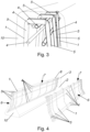
- the reinforcement element 1 is essentially shaped like a curved surface. This has the advantage that the reinforcement elements 1 can be easily stacked and thus transported in a space-saving manner.
- a stack of reinforcement elements 1 of the second preferred embodiment is shown in Fig. 5 shown as an example.
- the reinforcement of the concrete barrier wall element 3 formed from at least one reinforcement element 1 is open on the front side 10. It can be provided that the reinforcement element 1 consists only of the first region 6.
- a second region 7 adjoins the first region 6, that the second region 7 is angled relative to the first region 6 and is provided to be arranged on an upper side 8 of the concrete barrier element 3.
- the second region 7 can extend at least over half the width of the upper side 8.
- the upper side 8 can also be reinforced in this way.
- a third region 9 is provided on the second Area 7 adjoins, and that the third area 9 essentially has the deflection profile.
- the first area 6, the second area 7 and the third area 9 essentially form the profile of the two long sides 2 together with the top 8 of the concrete barrier wall element 3 to be produced.
- the concrete barrier wall element 3 it can be provided that the concrete barrier wall element 3 has two long sides 2 having a deflection profile, and that a single reinforcement element 1 is arranged on both long sides 2.
- the concrete barrier wall element 3 has only a single reinforcement element 1.
- reinforcement of all exposed surfaces of a concrete barrier wall element 3 can be achieved by essentially a single prefabricated reinforcement element 1.
- Such a concrete barrier wall element 3 is shown by way of example in Fig. 1 shown.
- the reinforcement element 1 has only the first region 6 and the second region 7.
- the concrete barrier element 3 has two longitudinal sides 2 having a deflection profile, and that a reinforcement element 1 is arranged on each of the two longitudinal sides 2.
- the concrete barrier element 3 can preferably have two, in particular essentially identically designed, reinforcement elements 1, with one of the reinforcement elements 1 being particularly preferably arranged on one of the long sides 2.
- This multi-part structure of the reinforcement can simplify the handling of the reinforcement elements 1. Furthermore, stackability is improved.
- reinforcement elements 1 can also be used in concrete barrier elements 3 that only have one long side 2 with the deflection profile. Reinforcement elements 1 designed in this way are shown by way of example in Fig. 2 to 5 shown, where in Fig. 2 both reinforcement elements 1 are shown joined together, while in Fig. 4 one reinforcement element 1 is shown inside the concrete body and the other reinforcement element 1 is shown outside the concrete body.
- the two reinforcement elements 1 adjoin one another, in particular overlap, in the region of an upper side 8 of the concrete barrier wall element 3.
- both reinforcement elements 1 can be easily connected to one another in the region of the upper side 8.
- the brackets 5 of the two reinforcement elements 1 can be slightly offset from one another so that they are arranged next to one another in the second region 7.
Landscapes
- Engineering & Computer Science (AREA)
- Architecture (AREA)
- Civil Engineering (AREA)
- Structural Engineering (AREA)
- Manufacturing & Machinery (AREA)
- Chemical & Material Sciences (AREA)
- Ceramic Engineering (AREA)
- Mechanical Engineering (AREA)
- Reinforcement Elements For Buildings (AREA)
- Refuge Islands, Traffic Blockers, Or Guard Fence (AREA)
- Panels For Use In Building Construction (AREA)
- Building Environments (AREA)
- Fencing (AREA)
Claims (12)
- Elément de renforcement (1) pour un élément de paroi en béton (3), lequel élément de paroi en béton a un profil repoussant sur au moins un côté longitudinal (2), dans lequel le profil repoussant est un profil New Jersey ou un profil en escalier, dans lequel l'élément de renforcement (1) a des barres de renforcement longitudinales (4) et a des arcs (5), qui s'étendent transversalement aux barres de renforcement longitudinales (4) et sont soudés aux barres de renforcement longitudinales (4), que l'élément de renforcement (1) comporte au moins une première zone (6), que la première zone (6) est sensiblement formée comme le profil de répulsion de l'élément de barrière-mur en béton (3) à produire, caractérisé en ce que les barres de renforcement longitudinales (4) et les arcs (5) forment une grille courbe bidimensionnelle, et que l'élément de renforcement (1), afin d'être empilé facilement et donc transporté de manière peu encombrante, est plat et formé sensiblement comme une surface courbée.
- Elément de renforcement (1) selon la revendication 1, caractérisé en ce qu'une distance entre les arcs (5) est variable l'une par rapport à l'autre, et en particulier est plus petite dans une région des extrémités des barres de renforcement longitudinales (4) que dans une région centrale des barres de renforcement longitudinales (4).
- Elément de renforcement (1) selon la revendication 1 ou 2, caractérisé en ce qu'une distance entre les barres de renforcement longitudinales (4) est variable l'une par rapport à l'autre, et en particulier est plus petite dans les régions des bords du profil de repoussement que dans une région centrale du profil de repoussement.
- Elément de renforcement (1) selon l'une des revendications 1 à 3, caractérisé en ce qu'une distance entre les barres de renforcement longitudinales (4) est plus petite l'une par rapport à l'autre dans une région des extrémités des arcs (5) que dans une région centrale des arcs (5).
- Elément de renforcement (1) selon l'une des revendications 1 à 4, caractérisé en ce que les barres de renforcement longitudinales (4) ont un diamètre différent de celui des arcs (5).
- Elément de renforcement (1) selon l'une des revendications 1 à 5, caractérisé en ce qu'une deuxième zone (7) jouxte la première zone (6), en ce que la deuxième zone (7) est inclinée par rapport à la première zone (6) et est prévue pour être disposée sur une face supérieure (8) de l'élément de mur-barrière en béton (3).
- Elément de renforcement (1) selon la revendication 6, caractérisé en ce que l'élément de renforcement (1) a seulement la première région (6) et la deuxième région (7).
- Elément de paroi en béton (3) pour un système de retenue de véhicule, lequel élément de paroi en béton (3) a un profil de répulsion sur au moins un côté longitudinal (2), dans lequel un élément de renforcement (1) selon l'une des revendications 1 à 7 est disposé près de la surface dans la zone d'au moins un côté longitudinal (2).
- Elément de paroi en béton (3) selon la revendication 8, caractérisé en ce que l'élément de paroi en béton (3) a deux côtés longitudinaux (2) ayant un profil repoussant, et en ce qu'un élément de renforcement (1) est disposé sur les deux côtés longitudinaux (2).
- Elément de paroi en béton (3) selon la revendication 8 ou 9, caractérisé en ce que les deux éléments de renforcement (1) sont au moins adjacents l'un à l'autre, en particulier se chevauchent dans la région d'un côté supérieur (8) de l'élément de paroi en béton (3).
- Procédé de fabrication d'un élément de paroi en béton (3) présentant un profil repoussant sur au moins un côté longitudinal (2), dans lequel le profil repoussant est un profil New Jersey ou un profil en escalier, dans lequel des barres d'armature longitudinales (4) et des arcs (5), qui s'étendent transversalement aux barres d'armature longitudinales (4), sont reliés entre eux pour former une armature de renforcement, sont reliés ensemble pour former un élément de renforcement (1), lequel élément de renforcement (1) a au moins une première région (6), dans laquelle la première région (6) est substantiellement formée comme le profil repoussant de l'élément de barrière-mur en béton (3) à produire, dans lequel une grille courbe bidimensionnelle est construite au moyen des barres de renforcement longitudinales (4) et des arcs (5), dans lequel l'élément de renforcement (1) est formé essentiellement comme une surface courbe, dans lequel au moins un des éléments de renforcement (1) est introduit dans un moule de coulée de telle sorte que le au moins un élément de renforcement (1) est disposé près de la surface dans la région d'au moins un côté longitudinal (2) dans l'élément de mur de barrière en béton fini (3), dans lequel le moule de coulée est coulé avec du béton pour former l'élément de mur de barrière en béton (3).
- Procédé selon la revendication 11, caractérisé en ce que les éléments de renforcement (1) sont fabriqués à la machine.
Priority Applications (2)
| Application Number | Priority Date | Filing Date | Title |
|---|---|---|---|
| HRP20250053TT HRP20250053T1 (hr) | 2016-12-07 | 2017-11-27 | Armaturni element |
| RS20250012A RS66378B1 (sr) | 2016-12-07 | 2017-11-27 | Armaturni element |
Applications Claiming Priority (2)
| Application Number | Priority Date | Filing Date | Title |
|---|---|---|---|
| ATA51118/2016A AT518889B1 (de) | 2016-12-07 | 2016-12-07 | Bewehrungselement |
| PCT/EP2017/080537 WO2018104094A1 (fr) | 2016-12-07 | 2017-11-27 | Élément d'armature |
Publications (3)
| Publication Number | Publication Date |
|---|---|
| EP3551803A1 EP3551803A1 (fr) | 2019-10-16 |
| EP3551803B1 true EP3551803B1 (fr) | 2024-12-18 |
| EP3551803C0 EP3551803C0 (fr) | 2024-12-18 |
Family
ID=60702630
Family Applications (1)
| Application Number | Title | Priority Date | Filing Date |
|---|---|---|---|
| EP17816523.9A Active EP3551803B1 (fr) | 2016-12-07 | 2017-11-27 | Élément d'armature |
Country Status (25)
| Country | Link |
|---|---|
| US (1) | US11028546B2 (fr) |
| EP (1) | EP3551803B1 (fr) |
| JP (1) | JP2020501045A (fr) |
| KR (1) | KR20190092465A (fr) |
| CN (1) | CN110168168A (fr) |
| AT (1) | AT518889B1 (fr) |
| AU (1) | AU2017373483B2 (fr) |
| BR (1) | BR112019010609B1 (fr) |
| CA (1) | CA3046043A1 (fr) |
| CL (1) | CL2019001460A1 (fr) |
| ES (1) | ES3002232T3 (fr) |
| HR (1) | HRP20250053T1 (fr) |
| HU (1) | HUE069867T2 (fr) |
| IL (1) | IL267053B (fr) |
| MA (1) | MA48593A (fr) |
| MX (1) | MX2019006355A (fr) |
| NZ (1) | NZ754017A (fr) |
| PE (1) | PE20191122A1 (fr) |
| PL (1) | PL3551803T3 (fr) |
| RS (1) | RS66378B1 (fr) |
| RU (1) | RU2756443C2 (fr) |
| TN (1) | TN2019000169A1 (fr) |
| UA (1) | UA128520C2 (fr) |
| WO (1) | WO2018104094A1 (fr) |
| ZA (1) | ZA201904435B (fr) |
Families Citing this family (2)
| Publication number | Priority date | Publication date | Assignee | Title |
|---|---|---|---|---|
| CN113021602A (zh) * | 2021-02-09 | 2021-06-25 | 浙江交工集团股份有限公司 | 一种预制装配式桥梁钢套立柱施工方法 |
| US20240110348A1 (en) * | 2022-09-30 | 2024-04-04 | Investissements Qmb Inc. | Barrier for roadway |
Citations (1)
| Publication number | Priority date | Publication date | Assignee | Title |
|---|---|---|---|---|
| US6394410B1 (en) * | 2000-07-06 | 2002-05-28 | Randy L. Thompson | Adjustable reinforcement insertion guide for a slip form concrete barrier mold |
Family Cites Families (26)
| Publication number | Priority date | Publication date | Assignee | Title |
|---|---|---|---|---|
| US3308724A (en) * | 1963-10-08 | 1967-03-14 | Smith Henry Such | Roadway guard rail barrier |
| US3678815A (en) * | 1970-08-27 | 1972-07-25 | George C Younker | Concrete structural member |
| US4084928A (en) * | 1976-11-03 | 1978-04-18 | Cmi Corporation | Slip form having reinforcement accommodating means |
| US4423854A (en) * | 1979-11-26 | 1984-01-03 | International Barrier Corporation | Roadway barrier |
| US4494892A (en) * | 1982-12-29 | 1985-01-22 | Henri Vidal | Traffic barrier, barrier element and method of construction |
| US4605336A (en) * | 1984-07-12 | 1986-08-12 | Slaw Sr Robert A | Joint construction of concrete members |
| US4668462A (en) * | 1986-01-17 | 1987-05-26 | Fomico International, Inc. | Adjustable mold for concrete median barrier |
| US4806044A (en) * | 1988-05-20 | 1989-02-21 | Barrier Systems, Inc. | Anti-crash lane barrier with self-centering hinges |
| JP3165514B2 (ja) * | 1992-08-13 | 2001-05-14 | 太平洋セメント株式会社 | コンクリート製ガードフェンス |
| JP2588117B2 (ja) * | 1992-08-19 | 1997-03-05 | 住倉鋼材株式会社 | コンクリート構造物を築造する方法 |
| US5651635A (en) * | 1995-04-24 | 1997-07-29 | Schuylkill Products, Inc. | Concrete barrier with reinforcement |
| JP2763279B2 (ja) * | 1995-09-14 | 1998-06-11 | 旭コンクリート工業株式会社 | コンクリートガードフェンスの施工方法 |
| US5685665A (en) * | 1996-05-09 | 1997-11-11 | Lembo; M. Carl | Roadway barrier and method of installation |
| JP2948149B2 (ja) * | 1996-06-19 | 1999-09-13 | ミサワセラミックス株式会社 | コンクリート防護柵の構造および施工方法 |
| NL1012439C2 (nl) * | 1999-06-25 | 2001-01-10 | Haitsma Beton Bv | Afscheidingselement. |
| FR2801913A1 (fr) * | 1999-12-07 | 2001-06-08 | Bernard Abram | Dispositif pour mise en continuite d'elements de barriere de securite routiere |
| US6526721B1 (en) * | 2000-05-26 | 2003-03-04 | Brian D. Nash | Fluid-impervious barrier/keyway form support apparatus, system and related method |
| US6679649B1 (en) * | 2002-12-27 | 2004-01-20 | Sps New England, Inc. | Barrier wall apparatus and method of construction |
| FR2862674B1 (fr) * | 2003-11-20 | 2007-05-25 | Bonna Sabla | Realisation d'une barriere de securite pour voie de circulation routiere |
| JP2008095363A (ja) * | 2006-10-11 | 2008-04-24 | Fair Design:Kk | ガードフェンス |
| AT507611B1 (de) * | 2008-11-20 | 2010-08-15 | Mathias Mag Redlberger | Verbindungseinrichtung zum verbinden von trennelementen für verkehrsflächen |
| AT11483U1 (de) * | 2009-06-15 | 2010-11-15 | Kirchdorfer Fertigteilholding | Zugelement |
| GB2492773B (en) * | 2011-07-11 | 2016-08-17 | Francis Maydew Nigel | Barricade component |
| WO2014036237A1 (fr) * | 2012-09-01 | 2014-03-06 | Easi-Set Industries, Inc. | Structure de barrière d'autoroute à enclenchement |
| US9869066B2 (en) | 2013-11-27 | 2018-01-16 | Howard Cooper | System and method for slip forming concrete barriers |
| US9598827B1 (en) * | 2016-08-20 | 2017-03-21 | Victor Nicholas Pavloff, Jr. | Barrier rail retrofit device assembly |
-
2016
- 2016-12-07 AT ATA51118/2016A patent/AT518889B1/de active
-
2017
- 2017-11-27 EP EP17816523.9A patent/EP3551803B1/fr active Active
- 2017-11-27 BR BR112019010609-0A patent/BR112019010609B1/pt active IP Right Grant
- 2017-11-27 NZ NZ754017A patent/NZ754017A/en unknown
- 2017-11-27 JP JP2019531291A patent/JP2020501045A/ja active Pending
- 2017-11-27 PL PL17816523.9T patent/PL3551803T3/pl unknown
- 2017-11-27 MX MX2019006355A patent/MX2019006355A/es unknown
- 2017-11-27 PE PE2019001086A patent/PE20191122A1/es unknown
- 2017-11-27 CN CN201780074457.9A patent/CN110168168A/zh active Pending
- 2017-11-27 CA CA3046043A patent/CA3046043A1/fr active Pending
- 2017-11-27 UA UAA201906236A patent/UA128520C2/uk unknown
- 2017-11-27 HU HUE17816523A patent/HUE069867T2/hu unknown
- 2017-11-27 RS RS20250012A patent/RS66378B1/sr unknown
- 2017-11-27 AU AU2017373483A patent/AU2017373483B2/en active Active
- 2017-11-27 KR KR1020197018680A patent/KR20190092465A/ko not_active Ceased
- 2017-11-27 WO PCT/EP2017/080537 patent/WO2018104094A1/fr not_active Ceased
- 2017-11-27 ES ES17816523T patent/ES3002232T3/es active Active
- 2017-11-27 TN TNP/2019/000169A patent/TN2019000169A1/en unknown
- 2017-11-27 HR HRP20250053TT patent/HRP20250053T1/hr unknown
- 2017-11-27 MA MA048593A patent/MA48593A/fr unknown
- 2017-11-27 US US16/467,663 patent/US11028546B2/en active Active
- 2017-11-27 RU RU2019120989A patent/RU2756443C2/ru active
-
2019
- 2019-05-29 CL CL2019001460A patent/CL2019001460A1/es unknown
- 2019-06-03 IL IL267053A patent/IL267053B/en active IP Right Grant
- 2019-07-05 ZA ZA2019/04435A patent/ZA201904435B/en unknown
Patent Citations (1)
| Publication number | Priority date | Publication date | Assignee | Title |
|---|---|---|---|---|
| US6394410B1 (en) * | 2000-07-06 | 2002-05-28 | Randy L. Thompson | Adjustable reinforcement insertion guide for a slip form concrete barrier mold |
Also Published As
| Publication number | Publication date |
|---|---|
| BR112019010609B1 (pt) | 2023-01-24 |
| CA3046043A1 (fr) | 2018-06-14 |
| EP3551803C0 (fr) | 2024-12-18 |
| US11028546B2 (en) | 2021-06-08 |
| AT518889A4 (de) | 2018-02-15 |
| AU2017373483B2 (en) | 2023-04-06 |
| RU2019120989A3 (fr) | 2021-03-26 |
| IL267053B (en) | 2019-09-26 |
| AT518889B1 (de) | 2018-02-15 |
| CN110168168A (zh) | 2019-08-23 |
| TN2019000169A1 (en) | 2020-10-05 |
| ES3002232T3 (en) | 2025-03-06 |
| PE20191122A1 (es) | 2019-08-28 |
| WO2018104094A1 (fr) | 2018-06-14 |
| RS66378B1 (sr) | 2025-02-28 |
| JP2020501045A (ja) | 2020-01-16 |
| MA48593A (fr) | 2020-03-18 |
| CL2019001460A1 (es) | 2019-09-13 |
| PL3551803T3 (pl) | 2025-03-31 |
| HRP20250053T1 (hr) | 2025-03-14 |
| HUE069867T2 (hu) | 2025-04-28 |
| IL267053A (en) | 2019-07-31 |
| AU2017373483A1 (en) | 2019-07-04 |
| NZ754017A (en) | 2025-05-02 |
| US20200087875A1 (en) | 2020-03-19 |
| BR112019010609A2 (pt) | 2019-09-17 |
| UA128520C2 (uk) | 2024-08-07 |
| EP3551803A1 (fr) | 2019-10-16 |
| RU2756443C2 (ru) | 2021-09-30 |
| KR20190092465A (ko) | 2019-08-07 |
| ZA201904435B (en) | 2021-05-26 |
| MX2019006355A (es) | 2019-10-21 |
| RU2019120989A (ru) | 2021-01-11 |
Similar Documents
| Publication | Publication Date | Title |
|---|---|---|
| EP1927699B1 (fr) | Muret de séparation du trafic | |
| EP2322719A2 (fr) | Dispositifs destinés à enjamber des joints de dilatation, construction de profilé et procédé de fabrication de profilés de joints | |
| EP2075388B1 (fr) | Eléments d'armature et pièces en béton armé ou précontraint ainsi produites avec ces éléments d'armature | |
| EP3697980B1 (fr) | Verrou horizontal | |
| EP3551803B1 (fr) | Élément d'armature | |
| EP2623435A1 (fr) | Conteneur palette empilable et enveloppe extérieure en treillis métallique pour ledit conteneur | |
| EP2209952B1 (fr) | Élément d'écartement et composant pour la production d'une structure murale, et procédé et dispositif correspondants | |
| EP2025816B1 (fr) | Procédé de fabrication d'un élément de muret et élément de muret fabriqué après le procédé pour un muret de séparation du trafic | |
| EP3201397B1 (fr) | Muret de séparation du trafic | |
| EP2826650B1 (fr) | Cadre d'un toit coulissant de véhicule avec canaux de câbles | |
| EP2446088B1 (fr) | Élément de bout | |
| DE10116673A1 (de) | Transportanker | |
| AT512411B1 (de) | Ortbetonschutzwand | |
| DE29821624U1 (de) | Verbindungselement für Spundbohlen | |
| EP4621129A1 (fr) | Profilé de coffre pour système de retenue de véhicule et procédé de fabrication de ce profilé de coffre | |
| EP1878846B1 (fr) | Cage de liaison, son utilisation et armature de liaison ainsi réalisée | |
| DE4207434C2 (de) | Befestigungselement | |
| DE20023821U1 (de) | Schachtabdeckung | |
| DE29512788U1 (de) | Schubbewehrung für Betonbauteile | |
| DE4225640A1 (de) | Anschlußbewehrungselement | |
| EP3608476A1 (fr) | Élément mural pour un mur de guidage et / ou de délimitation de la circulation | |
| EP0565940A1 (fr) | Douille avec lamelles inserée dans les cylindres du bloc moteur lors de la coulée | |
| DE102017119768A1 (de) | Schalung zur Herstellung von Industrieböden | |
| DE102012106249A1 (de) | Stoßfängerprofil | |
| DE2166871A1 (de) | Bewehrungsstab |
Legal Events
| Date | Code | Title | Description |
|---|---|---|---|
| REG | Reference to a national code |
Ref country code: HR Ref legal event code: TUEP Ref document number: P20250053T Country of ref document: HR |
|
| STAA | Information on the status of an ep patent application or granted ep patent |
Free format text: STATUS: UNKNOWN |
|
| STAA | Information on the status of an ep patent application or granted ep patent |
Free format text: STATUS: THE INTERNATIONAL PUBLICATION HAS BEEN MADE |
|
| PUAI | Public reference made under article 153(3) epc to a published international application that has entered the european phase |
Free format text: ORIGINAL CODE: 0009012 |
|
| STAA | Information on the status of an ep patent application or granted ep patent |
Free format text: STATUS: REQUEST FOR EXAMINATION WAS MADE |
|
| 17P | Request for examination filed |
Effective date: 20190708 |
|
| AK | Designated contracting states |
Kind code of ref document: A1 Designated state(s): AL AT BE BG CH CY CZ DE DK EE ES FI FR GB GR HR HU IE IS IT LI LT LU LV MC MK MT NL NO PL PT RO RS SE SI SK SM TR |
|
| AX | Request for extension of the european patent |
Extension state: BA ME |
|
| DAX | Request for extension of the european patent (deleted) | ||
| RAP1 | Party data changed (applicant data changed or rights of an application transferred) |
Owner name: DELTA BLOC INTERNATIONAL GMBH |
|
| STAA | Information on the status of an ep patent application or granted ep patent |
Free format text: STATUS: EXAMINATION IS IN PROGRESS |
|
| 17Q | First examination report despatched |
Effective date: 20200617 |
|
| RAP3 | Party data changed (applicant data changed or rights of an application transferred) |
Owner name: DELTABLOC INTERNATIONAL GMBH |
|
| GRAP | Despatch of communication of intention to grant a patent |
Free format text: ORIGINAL CODE: EPIDOSNIGR1 |
|
| STAA | Information on the status of an ep patent application or granted ep patent |
Free format text: STATUS: GRANT OF PATENT IS INTENDED |
|
| INTG | Intention to grant announced |
Effective date: 20240904 |
|
| GRAS | Grant fee paid |
Free format text: ORIGINAL CODE: EPIDOSNIGR3 |
|
| GRAA | (expected) grant |
Free format text: ORIGINAL CODE: 0009210 |
|
| STAA | Information on the status of an ep patent application or granted ep patent |
Free format text: STATUS: THE PATENT HAS BEEN GRANTED |
|
| AK | Designated contracting states |
Kind code of ref document: B1 Designated state(s): AL AT BE BG CH CY CZ DE DK EE ES FI FR GB GR HR HU IE IS IT LI LT LU LV MC MK MT NL NO PL PT RO RS SE SI SK SM TR |
|
| REG | Reference to a national code |
Ref country code: GB Ref legal event code: FG4D Free format text: NOT ENGLISH |
|
| REG | Reference to a national code |
Ref country code: CH Ref legal event code: EP |
|
| REG | Reference to a national code |
Ref country code: DE Ref legal event code: R096 Ref document number: 502017016619 Country of ref document: DE |
|
| REG | Reference to a national code |
Ref country code: IE Ref legal event code: FG4D Free format text: LANGUAGE OF EP DOCUMENT: GERMAN |
|
| U01 | Request for unitary effect filed |
Effective date: 20250103 |
|
| U07 | Unitary effect registered |
Designated state(s): AT BE BG DE DK EE FI FR IT LT LU LV MT NL PT RO SE SI Effective date: 20250115 |
|
| REG | Reference to a national code |
Ref country code: ES Ref legal event code: FG2A Ref document number: 3002232 Country of ref document: ES Kind code of ref document: T3 Effective date: 20250306 Ref country code: GR Ref legal event code: EP Ref document number: 20250400144 Country of ref document: GR Effective date: 20250211 |
|
| REG | Reference to a national code |
Ref country code: SK Ref legal event code: T3 Ref document number: E 45786 Country of ref document: SK |
|
| REG | Reference to a national code |
Ref country code: HR Ref legal event code: T1PR Ref document number: P20250053 Country of ref document: HR |
|
| REG | Reference to a national code |
Ref country code: HU Ref legal event code: AG4A Ref document number: E069867 Country of ref document: HU |
|
| PG25 | Lapsed in a contracting state [announced via postgrant information from national office to epo] |
Ref country code: SM Free format text: LAPSE BECAUSE OF FAILURE TO SUBMIT A TRANSLATION OF THE DESCRIPTION OR TO PAY THE FEE WITHIN THE PRESCRIBED TIME-LIMIT Effective date: 20241218 |
|
| PG25 | Lapsed in a contracting state [announced via postgrant information from national office to epo] |
Ref country code: IS Free format text: LAPSE BECAUSE OF FAILURE TO SUBMIT A TRANSLATION OF THE DESCRIPTION OR TO PAY THE FEE WITHIN THE PRESCRIBED TIME-LIMIT Effective date: 20250418 |
|
| VS25 | Lapsed in a validation state [announced via postgrant information from nat. office to epo] |
Ref country code: MD Free format text: LAPSE BECAUSE OF FAILURE TO SUBMIT A TRANSLATION OF THE DESCRIPTION OR TO PAY THE FEE WITHIN THE PRESCRIBED TIME-LIMIT Effective date: 20241218 |
|
| U20 | Renewal fee for the european patent with unitary effect paid |
Year of fee payment: 9 Effective date: 20250902 |
|
| PGFP | Annual fee paid to national office [announced via postgrant information from national office to epo] |
Ref country code: PL Payment date: 20250909 Year of fee payment: 9 |
|
| PLBE | No opposition filed within time limit |
Free format text: ORIGINAL CODE: 0009261 |
|
| STAA | Information on the status of an ep patent application or granted ep patent |
Free format text: STATUS: NO OPPOSITION FILED WITHIN TIME LIMIT |
|
| 26N | No opposition filed |
Effective date: 20250919 |
|
| PGFP | Annual fee paid to national office [announced via postgrant information from national office to epo] |
Ref country code: HU Payment date: 20251127 Year of fee payment: 9 |
|
| REG | Reference to a national code |
Ref country code: HR Ref legal event code: ODRP Ref document number: P20250053 Country of ref document: HR Payment date: 20251120 Year of fee payment: 9 |
|
| PGFP | Annual fee paid to national office [announced via postgrant information from national office to epo] |
Ref country code: GB Payment date: 20251120 Year of fee payment: 9 |
|
| PGFP | Annual fee paid to national office [announced via postgrant information from national office to epo] |
Ref country code: NO Payment date: 20251118 Year of fee payment: 9 |
|
| PGFP | Annual fee paid to national office [announced via postgrant information from national office to epo] |
Ref country code: HR Payment date: 20251120 Year of fee payment: 9 |
|
| PGFP | Annual fee paid to national office [announced via postgrant information from national office to epo] |
Ref country code: TR Payment date: 20251121 Year of fee payment: 9 Ref country code: GR Payment date: 20251117 Year of fee payment: 9 |
|
| PGFP | Annual fee paid to national office [announced via postgrant information from national office to epo] |
Ref country code: CZ Payment date: 20251118 Year of fee payment: 9 |
|
| PGFP | Annual fee paid to national office [announced via postgrant information from national office to epo] |
Ref country code: SK Payment date: 20251121 Year of fee payment: 9 |
|
| PGFP | Annual fee paid to national office [announced via postgrant information from national office to epo] |
Ref country code: RS Payment date: 20251114 Year of fee payment: 9 |
|
| PGFP | Annual fee paid to national office [announced via postgrant information from national office to epo] |
Ref country code: ES Payment date: 20251216 Year of fee payment: 9 |