EP3608476A1 - Élément mural pour un mur de guidage et / ou de délimitation de la circulation - Google Patents
Élément mural pour un mur de guidage et / ou de délimitation de la circulation Download PDFInfo
- Publication number
- EP3608476A1 EP3608476A1 EP19190046.3A EP19190046A EP3608476A1 EP 3608476 A1 EP3608476 A1 EP 3608476A1 EP 19190046 A EP19190046 A EP 19190046A EP 3608476 A1 EP3608476 A1 EP 3608476A1
- Authority
- EP
- European Patent Office
- Prior art keywords
- wall element
- wall
- profile
- compartment
- section
- Prior art date
- Legal status (The legal status is an assumption and is not a legal conclusion. Google has not performed a legal analysis and makes no representation as to the accuracy of the status listed.)
- Withdrawn
Links
Images


Classifications
-
- E—FIXED CONSTRUCTIONS
- E01—CONSTRUCTION OF ROADS, RAILWAYS, OR BRIDGES
- E01F—ADDITIONAL WORK, SUCH AS EQUIPPING ROADS OR THE CONSTRUCTION OF PLATFORMS, HELICOPTER LANDING STAGES, SIGNS, SNOW FENCES, OR THE LIKE
- E01F15/00—Safety arrangements for slowing, redirecting or stopping errant vehicles, e.g. guard posts or bollards; Arrangements for reducing damage to roadside structures due to vehicular impact
- E01F15/02—Continuous barriers extending along roads or between traffic lanes
- E01F15/08—Continuous barriers extending along roads or between traffic lanes essentially made of walls or wall-like elements ; Cable-linked blocks
- E01F15/081—Continuous barriers extending along roads or between traffic lanes essentially made of walls or wall-like elements ; Cable-linked blocks characterised by the use of a specific material
- E01F15/083—Continuous barriers extending along roads or between traffic lanes essentially made of walls or wall-like elements ; Cable-linked blocks characterised by the use of a specific material using concrete
-
- E—FIXED CONSTRUCTIONS
- E01—CONSTRUCTION OF ROADS, RAILWAYS, OR BRIDGES
- E01F—ADDITIONAL WORK, SUCH AS EQUIPPING ROADS OR THE CONSTRUCTION OF PLATFORMS, HELICOPTER LANDING STAGES, SIGNS, SNOW FENCES, OR THE LIKE
- E01F15/00—Safety arrangements for slowing, redirecting or stopping errant vehicles, e.g. guard posts or bollards; Arrangements for reducing damage to roadside structures due to vehicular impact
- E01F15/02—Continuous barriers extending along roads or between traffic lanes
- E01F15/08—Continuous barriers extending along roads or between traffic lanes essentially made of walls or wall-like elements ; Cable-linked blocks
- E01F15/088—Details of element connection
Definitions
- the invention relates to a wall element for a passive protective device for traffic protection, with a top, a bottom and two end faces of a closed compartment of the wall element circumferentially delimiting wall frame made of steel profile rails, at least one of the steel profile rails extending above, below or at the front of the compartment Crosspiece and two at least approximately perpendicular to the crosspiece, at the crosspiece ends adjoining side legs, which lie essentially in the plane of the wall element side surfaces or form them.
- traffic control and / or barrier walls are often built to protect them, which consist of individual wall elements that are provided or can be provided with pedestal elements at their end areas with which they can be used on the Traffic area in the wall longitudinal direction are parked one after the other and are generally connected to one another at their end faces.
- wall elements with a circumferential wall element frame made of lower, upper and right and left-hand (front) steel profiles, namely H and / or U profiles, which are welded together at their ends defining the corner regions of the wall element.
- the inner compartment delimited by the surrounding wall element frame made of steel profiles, is filled with concrete, with which very good impact protection is achieved.
- the high weight of such wall elements made of steel and concrete also ensures good stability of the wall element on the traffic area.
- the object of the invention is to improve the stability of known wall elements comprising a wall frame made of steel profile rails or consisting of such a wall frame.
- the side legs are provided at their leg ends spaced apart from the transverse web with leg end pieces angled inward in the profile cross section, preferably essentially at right angles to the wall element side surfaces of the wall element.
- This profile cross section which according to the invention is used for at least some of the steel profiles of the wall frame, and which can also be referred to as the "C profile" has a considerably greater section modulus against deflection due to the inwardly angled leg end pieces, which preferably run parallel to the main direction of the crossbar and torsion than known U or H profiles, so that deformations as a result of an accident occur less frequently.
- a particularly high stability of the wall element is obtained if, in a particularly preferred embodiment of the invention, the compartment is filled with concrete in such a way that it encloses the leg end pieces on both sides. After the concrete has hardened, a positive locking of the profile rail is obtained with the concrete surrounding it in the area of the leg end pieces on the side faces and the free end face, which considerably improves the load-bearing capacity of the wall element.
- the leg end pieces preferably each have an inward recess depth in the profile cross section which is less than a third, preferably less than a quarter, more preferably less than a fifth and in particular preferably less than a sixth of the width of the crosspiece. It has surprisingly been found that a greater recess depth, i.e.
- the extent to which the leg end pieces protrude inwards from the side legs into the profile cross section or the compartment delimited by the steel profiles does not improve the stability of the wall element, at least not appreciably, but that does if the recess depth is only a third, a quarter, a fifth or even a sixth of the thickness (width) of the wall element, the interior of the profile cross-section is also filled with concrete faster and more reliably when pouring out the compartment delimited by the wall frame, and special measures such as, for example the use of compaction equipment (vibrating bottles) in the area of the rail profile is not particularly necessary.
- the transverse web is preferably provided with a central web trough which is drawn into the interior of the wall frame in the direction of the leg end pieces in order to form a ⁇ -shaped profile cross section.
- a sigma-shaped profile cross section has a particularly high section modulus and thus leads to a very high stiffness of the steel profile even over a comparatively large length, so that such a profile is also very suitable for a wall element in which the compartment is filled with concrete is waived. It goes without saying that a steel-concrete wall element, at which uses a sigma profile for the profile rails, has a particularly high level of stability.
- the web trough preferably has a trough depth which is approximately 1/3 to 1/2 the height of the side legs.
- the web trough can have an approximately trapezoidal cross-section with inclined surfaces on the edge and a base surface extending between them over a partial width of the wall thickness of the wall element, the inclined surfaces preferably merging substantially directly into the side legs at their outer ends, forming a radius.
- the steel profile rails can have fundamentally different cross sections on the top and on the bottom and / or on the two end faces, but they preferably each have the same profile cross section, because this not only ensures the same high rigidity all round, but also simplifies procurement, storage and not finally the assembly of the profile rails on the front sides with those on the top and bottom by (preferably) welding in the corner areas of the wall frame.
- reinforcement inserts it is possible for reinforcement inserts to extend between the steel profile rails arranged on the top and the bottom and / or between the end faces, which reinforce the concrete which fills the compartment delimited by the wall frame.
- the arrangement is preferably such that the reinforcement inserts are connected to the crossbars, in particular welded on.
- the 1 to 3 show a total of 10 designated wall element for a passive protection system, namely a traffic control wall, such as those used to block / secure construction sites and the like. can be built on roads or other traffic areas.
- a large number of wall elements 10 are set up in succession in the longitudinal direction 11 of the wall on the traffic area 12 and are firmly connected to one another at their end faces 13, 14, as is known per se.
- the wall element 10 has a truss-like construction 15 made of steel profiles, namely of two obliquely arranged, frontal profile rails 16, 17 and a total of three mutually parallel, horizontal profile rails 18, 19, 20, all of which are made of steel.
- the arrangement in the exemplary embodiment of the wall element 10 shown here is such that a lower compartment 21 of the truss or frame construction 15 is delimited by a wall frame 22, which is separated from the lower profile rail 18 and the central profile rail 19 and the lower regions of the front Profile rail sections 16, 17 is formed.
- the wall frame 22 is filled with concrete and thereby forms a wall pane with parallel, right and left side surfaces 23, 24.
- the wall element 10 is provided at its front end regions with end base elements 25, 26 which are welded to the lower profile rails 18 at the bottom, whereby they protrude laterally above them, so that they ensure a sufficiently large safety against tipping of the wall element ,
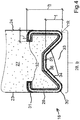
- Fig. 4 shows a section through the lower region of the compartment 21 filled with concrete 27 with the lower profile rail 18 of the wall element 10.
- the lower profile rail has 18 a transverse web 28 running on the underside of the compartment 21 over the thickness (width) of the wall element 10 and two side legs 29 extending at right angles to the transverse web 28, which connect to the transverse web ends 30 and whose outer sides lie in the plane of the wall element side surfaces 23, 24.
- the side legs 29 are provided with leg end pieces 32 which are angled inward into the profile cross section and which, in the preferred embodiment shown, run essentially at right angles to the wall element side surfaces 23, 24 of the wall element, in the case of the lower steel profile rail concerned here 18 in the horizontal direction.
- the (middle) profile rail 19 forming the upper boundary of the compartment 21 and the uppermost profile rail 20 delimiting the wall elements upward also have a cross section as in FIG Figure 4 shown on, but they are mirror images of the lower rail 18 so that their profile cross-section is open downwards.
- the cross bar 28 is provided in the middle with a web recess 33 drawn into the wall frame interior in the direction of the leg end pieces 32, so that the entire profile cross section is given a ⁇ -shaped shape.
- the web trough 33 has a trough depth t which is approximately 50% of the height h of the side legs 32.
- the web trough 33 has an approximately trapezoidal cross section with inclined surfaces 34 on the edge and a base surface 35 extending between them over a partial width of the wall thickness of the wall element 10.
- the inclined surfaces 34 essentially go directly into the transverse web ends 30 to form a radius R. the side legs 32 over.
- the leg end pieces 32 each have an inward recess depth r in the profile cross section, which is approximately one sixth of the width b of the cross piece 28 or is somewhat shorter. Thus approximately 2/3 of the width b of the profile cross section between the two leg end pieces 32 remain open to the profile interior 38.
- the compartment 21 is filled with the concrete 27 such that it encloses the leg end pieces 32 on both sides and also completely fills the profile interior 36.
- This will make the lower one Profile rail 18 and in a corresponding manner the central profile rail 19 is positively connected to the concrete 27 as soon as it sets and hardens after being filled into the compartment.
- the connection made in this way between concrete and steel is particularly stable, the leg end pieces 32 which form-fit in the concrete additionally stabilize the inherently stable Sigma profile of the steel profile rails 18, 19 with a high modulus of resistance, so that it is even in the event of a violent impact of a vehicle on the wall element remains dimensionally stable in its entirety and can be used in most cases after an accident.
- end faces of the wall element can also be bordered or formed with a steel profile, as shown in FIG Fig. 4 is shown.
- reinforcement inserts (not shown) provided between the end profiles 16, 17 and / or between the two profiles 18, 19 delimiting the compartment 21 below and above, which are preferably on the profiles on the right and left and / or above and below, in particular on the The inside of the base area, which are welded on and which are enclosed by this when the compartment is filled with concrete, lead to a further improvement in the stability of the wall element.
Landscapes
- Engineering & Computer Science (AREA)
- Architecture (AREA)
- Civil Engineering (AREA)
- Structural Engineering (AREA)
- Refuge Islands, Traffic Blockers, Or Guard Fence (AREA)
Applications Claiming Priority (1)
| Application Number | Priority Date | Filing Date | Title |
|---|---|---|---|
| DE102018119048.4A DE102018119048A1 (de) | 2018-08-06 | 2018-08-06 | Wandelement für eine Verkehrsleit- und/oder absperrwand |
Publications (1)
| Publication Number | Publication Date |
|---|---|
| EP3608476A1 true EP3608476A1 (fr) | 2020-02-12 |
Family
ID=67551068
Family Applications (1)
| Application Number | Title | Priority Date | Filing Date |
|---|---|---|---|
| EP19190046.3A Withdrawn EP3608476A1 (fr) | 2018-08-06 | 2019-08-05 | Élément mural pour un mur de guidage et / ou de délimitation de la circulation |
Country Status (2)
| Country | Link |
|---|---|
| EP (1) | EP3608476A1 (fr) |
| DE (1) | DE102018119048A1 (fr) |
Citations (5)
| Publication number | Priority date | Publication date | Assignee | Title |
|---|---|---|---|---|
| EP2025816A1 (fr) | 2007-08-01 | 2009-02-18 | AVS Mellingen GmbH | Procédé de fabrication d'un élément de muret et élément de muret fabriqué après le procédé pour un muret de séparation du trafic |
| DE102008052124A1 (de) * | 2008-10-20 | 2010-04-22 | Avs Mellingen Gmbh | Verkehrsleitwand |
| DE202012003240U1 (de) * | 2012-03-30 | 2012-05-07 | Horst Luther | Schutzwand und Schutzwandelement zur Herstellung einer solchen |
| DE202012009387U1 (de) * | 2012-10-01 | 2012-10-25 | Horst Luther | Vorrichtung zum Verbinden zweier mobiler Schutzwandelemente |
| DE102012110437A1 (de) * | 2012-03-02 | 2013-09-05 | Max Bögl Verkehrstechnik GmbH | Verkehrsleitwand mit Wandsegmenten und Verbindungselementen |
Family Cites Families (1)
| Publication number | Priority date | Publication date | Assignee | Title |
|---|---|---|---|---|
| KR200464087Y1 (ko) * | 2010-03-17 | 2012-12-12 | 이주식 | 목재를 이용한 안전펜스 결합구조 |
-
2018
- 2018-08-06 DE DE102018119048.4A patent/DE102018119048A1/de active Pending
-
2019
- 2019-08-05 EP EP19190046.3A patent/EP3608476A1/fr not_active Withdrawn
Patent Citations (5)
| Publication number | Priority date | Publication date | Assignee | Title |
|---|---|---|---|---|
| EP2025816A1 (fr) | 2007-08-01 | 2009-02-18 | AVS Mellingen GmbH | Procédé de fabrication d'un élément de muret et élément de muret fabriqué après le procédé pour un muret de séparation du trafic |
| DE102008052124A1 (de) * | 2008-10-20 | 2010-04-22 | Avs Mellingen Gmbh | Verkehrsleitwand |
| DE102012110437A1 (de) * | 2012-03-02 | 2013-09-05 | Max Bögl Verkehrstechnik GmbH | Verkehrsleitwand mit Wandsegmenten und Verbindungselementen |
| DE202012003240U1 (de) * | 2012-03-30 | 2012-05-07 | Horst Luther | Schutzwand und Schutzwandelement zur Herstellung einer solchen |
| DE202012009387U1 (de) * | 2012-10-01 | 2012-10-25 | Horst Luther | Vorrichtung zum Verbinden zweier mobiler Schutzwandelemente |
Also Published As
| Publication number | Publication date |
|---|---|
| DE102018119048A1 (de) | 2020-02-06 |
Similar Documents
| Publication | Publication Date | Title |
|---|---|---|
| DE102008023340B4 (de) | Aggregateträger für ein Getriebe eines Kraftfahrzeugs | |
| EP0874940B1 (fr) | Agencement de profiles de protection | |
| DE69711701T2 (de) | Mittelstreifenleitplanken | |
| EP2125479B1 (fr) | Élément de dissipation d'énergie de choc pour véhicule | |
| DE202007010798U1 (de) | Übergangsvorrichtung von einer Betonschutzwand auf eine Stahlschutzplanke an Straßen | |
| DE19948830A1 (de) | Teleskopausleger für Krane | |
| EP2075388B1 (fr) | Eléments d'armature et pièces en béton armé ou précontraint ainsi produites avec ces éléments d'armature | |
| DE69007748T2 (de) | Stahlschutzplankeneinrichtung. | |
| DE3809470C2 (fr) | ||
| DE2640910C3 (de) | Als Lärmschutzwand und Leiteinrichtung dienende Schutzwand | |
| WO2009015816A1 (fr) | Procédé de fabrication d'un élément de paroi | |
| EP3608476A1 (fr) | Élément mural pour un mur de guidage et / ou de délimitation de la circulation | |
| DE1010390B (de) | Bauteil aus Blech, insbesondere fuer lasttragende Fahrzeuge | |
| DE202012104881U1 (de) | Barriereelement und Barriere aus zumindest zwei miteinander verbundenen Barriereelementen | |
| DE3635990C1 (en) | Impact damper | |
| DE29707447U1 (de) | Übergang bei Verkehrswegen von einer Betongleitwand auf eine Schutzplankeneinrichtung | |
| EP1876300B1 (fr) | Barrière de sécurité d'acier | |
| DE102009028904A1 (de) | Leitplanke oder Schutzplanke, bestehend aus einem einzigen Element oder aus mehreren in Längsrichtung aneinandergekoppelten Elementen | |
| DE102007026919A1 (de) | Schutzplankenanordnung | |
| EP0826833B1 (fr) | Bloc séparateur pour voies de circulation | |
| DE102014209121B4 (de) | Übergangskonstruktion für Fahrbahnbegrenzungen | |
| DE10250505B3 (de) | Vorrichtung zum Schutz eines Bauwerkes gegen Anprall von Schienenfahrzeugen | |
| DE102008039851B4 (de) | Fahrzeugrückhaltesystem | |
| EP2423385B1 (fr) | Glissière de sécurité pour un dispositif de sécurité sur une route et procédé de fabrication d'une glissière de sécurité | |
| DE10124842B4 (de) | Stählerne Eisenbahnbrücke sowie Aufnahmesystem für Schienen |
Legal Events
| Date | Code | Title | Description |
|---|---|---|---|
| PUAI | Public reference made under article 153(3) epc to a published international application that has entered the european phase |
Free format text: ORIGINAL CODE: 0009012 |
|
| AK | Designated contracting states |
Kind code of ref document: A1 Designated state(s): AL AT BE BG CH CY CZ DE DK EE ES FI FR GB GR HR HU IE IS IT LI LT LU LV MC MK MT NL NO PL PT RO RS SE SI SK SM TR |
|
| AX | Request for extension of the european patent |
Extension state: BA ME |
|
| STAA | Information on the status of an ep patent application or granted ep patent |
Free format text: STATUS: THE APPLICATION IS DEEMED TO BE WITHDRAWN |
|
| 18D | Application deemed to be withdrawn |
Effective date: 20200813 |