EP3551803B1 - Reinforcing element - Google Patents
Reinforcing element Download PDFInfo
- Publication number
- EP3551803B1 EP3551803B1 EP17816523.9A EP17816523A EP3551803B1 EP 3551803 B1 EP3551803 B1 EP 3551803B1 EP 17816523 A EP17816523 A EP 17816523A EP 3551803 B1 EP3551803 B1 EP 3551803B1
- Authority
- EP
- European Patent Office
- Prior art keywords
- region
- longitudinal
- concrete barrier
- reinforcing
- profile
- Prior art date
- Legal status (The legal status is an assumption and is not a legal conclusion. Google has not performed a legal analysis and makes no representation as to the accuracy of the status listed.)
- Active
Links
Images


Classifications
-
- B—PERFORMING OPERATIONS; TRANSPORTING
- B28—WORKING CEMENT, CLAY, OR STONE
- B28B—SHAPING CLAY OR OTHER CERAMIC COMPOSITIONS; SHAPING SLAG; SHAPING MIXTURES CONTAINING CEMENTITIOUS MATERIAL, e.g. PLASTER
- B28B23/00—Arrangements specially adapted for the production of shaped articles with elements wholly or partly embedded in the moulding material; Production of reinforced objects
- B28B23/02—Arrangements specially adapted for the production of shaped articles with elements wholly or partly embedded in the moulding material; Production of reinforced objects wherein the elements are reinforcing members
-
- B—PERFORMING OPERATIONS; TRANSPORTING
- B29—WORKING OF PLASTICS; WORKING OF SUBSTANCES IN A PLASTIC STATE IN GENERAL
- B29C—SHAPING OR JOINING OF PLASTICS; SHAPING OF MATERIAL IN A PLASTIC STATE, NOT OTHERWISE PROVIDED FOR; AFTER-TREATMENT OF THE SHAPED PRODUCTS, e.g. REPAIRING
- B29C39/00—Shaping by casting, i.e. introducing the moulding material into a mould or between confining surfaces without significant moulding pressure; Apparatus therefor
- B29C39/02—Shaping by casting, i.e. introducing the moulding material into a mould or between confining surfaces without significant moulding pressure; Apparatus therefor for making articles of definite length, i.e. discrete articles
- B29C39/10—Shaping by casting, i.e. introducing the moulding material into a mould or between confining surfaces without significant moulding pressure; Apparatus therefor for making articles of definite length, i.e. discrete articles incorporating preformed parts or layers, e.g. casting around inserts or for coating articles
-
- E—FIXED CONSTRUCTIONS
- E01—CONSTRUCTION OF ROADS, RAILWAYS, OR BRIDGES
- E01D—CONSTRUCTION OF BRIDGES, ELEVATED ROADWAYS OR VIADUCTS; ASSEMBLY OF BRIDGES
- E01D19/00—Structural or constructional details of bridges
- E01D19/10—Railings; Protectors against smoke or gases, e.g. of locomotives; Maintenance travellers; Fastening of pipes or cables to bridges
- E01D19/103—Parapets, railings ; Guard barriers or road-bridges
-
- E—FIXED CONSTRUCTIONS
- E01—CONSTRUCTION OF ROADS, RAILWAYS, OR BRIDGES
- E01F—ADDITIONAL WORK, SUCH AS EQUIPPING ROADS OR THE CONSTRUCTION OF PLATFORMS, HELICOPTER LANDING STAGES, SIGNS, SNOW FENCES, OR THE LIKE
- E01F15/00—Safety arrangements for slowing, redirecting or stopping errant vehicles, e.g. guard posts or bollards; Arrangements for reducing damage to roadside structures due to vehicular impact
- E01F15/02—Continuous barriers extending along roads or between traffic lanes
- E01F15/08—Continuous barriers extending along roads or between traffic lanes essentially made of walls or wall-like elements ; Cable-linked blocks
- E01F15/081—Continuous barriers extending along roads or between traffic lanes essentially made of walls or wall-like elements ; Cable-linked blocks characterised by the use of a specific material
- E01F15/083—Continuous barriers extending along roads or between traffic lanes essentially made of walls or wall-like elements ; Cable-linked blocks characterised by the use of a specific material using concrete
-
- E—FIXED CONSTRUCTIONS
- E04—BUILDING
- E04C—STRUCTURAL ELEMENTS; BUILDING MATERIALS
- E04C5/00—Reinforcing elements, e.g. for concrete; Auxiliary elements therefor
- E04C5/01—Reinforcing elements of metal, e.g. with non-structural coatings
- E04C5/06—Reinforcing elements of metal, e.g. with non-structural coatings of high bending resistance, i.e. of essentially three-dimensional extent, e.g. lattice girders
- E04C5/0604—Prismatic or cylindrical reinforcement cages composed of longitudinal bars and open or closed stirrup rods
- E04C5/0622—Open cages, e.g. connecting stirrup baskets
Definitions
- the invention relates to a reinforcement element according to the preamble of patent claim 1.
- Such reinforcement elements are used for concrete barrier elements of a vehicle restraint system.
- Concrete barrier elements are precast concrete parts which together form a vehicle restraint system designed to prevent vehicles from leaving the road or entering the oncoming lane.
- Such concrete barrier elements have a characteristic profile on at least one long side facing the road, which ensures that a vehicle approaching at an angle does not bounce off, but is diverted in a direction parallel to the long side.
- Concrete barrier elements usually have reinforcement, which is made up of several individual elements.
- the specific form of reinforcement depends on the retention effect to be achieved by the concrete barrier element, although for economic reasons it is also a goal to use as little reinforcement material as possible.
- the reinforcement usually has at least longitudinal reinforcement bars, which are intended to reduce bending or prevent the concrete barrier element from breaking in the event of an impact.
- the longitudinal reinforcement bars are often used in the middle.
- the longitudinal reinforcement bars are also often connected with stirrups to increase internal stability. To prevent spalling, especially in the head area of the concrete barrier elements, additional filigree structural steel mats are often used.
- a concrete barrier element with a bonded or welded reinforcement cage is known.
- the stirrups are arranged all the way around and are bent in such a way that they form the deflection profile.
- FR 2 862 674 A1 From the FR 2 862 674 A1 is a prefabricated concrete barrier element.
- the reinforcement is achieved by connecting longitudinal bars using stirrups, whereby the profile of the reinforcement is formed by two L-shaped stirrups and one U-shaped stirrup.
- the object of the invention is therefore to provide a reinforcement element of the type mentioned at the outset, with which the disadvantages mentioned can be avoided, with which a concrete barrier element can be manufactured with less effort, and at the same time has a reliably high retention effect with increased process reliability in the manufacturing process.
- the invention relates to a concrete barrier element according to claim 8.
- the invention relates to a method for producing a concrete barrier wall element having a deflection profile on at least one longitudinal side according to patent claim 11.
- the object of the invention is therefore to provide a method with which the aforementioned disadvantages can be avoided, with which a concrete barrier element can be produced with less effort and at the same time has a reliably high retention effect.
- the Fig. 1 to 5 show at least parts of preferred embodiments of a reinforcement element 1 for a concrete barrier wall element 3 having a deflection profile on at least one long side 2.
- the reinforcement element 1 is intended for use in a concrete barrier wall element 3, which concrete barrier wall element 3 has at least one long side 2 with a deflection profile.
- the deflection profile is a profile characteristic of concrete barrier wall elements 3 of vehicle restraint systems, which ensures that a vehicle driving diagonally onto the long side 2 does not bounce off, but is diverted in a direction of travel parallel to the long side 2.
- the reinforcement element 1 comprises longitudinal reinforcement bars 4 and stirrups 5 running transversely to the longitudinal reinforcement bars 4 and connected to the longitudinal reinforcement bars 4, preferably welded.
- the longitudinal reinforcement bars 4 are intended to run in the longitudinal direction in the concrete barrier wall element 3.
- the longitudinal reinforcement bars 4 are connected to one another by means of stirrups 5.
- a two-dimensional, curved grid is preferably constructed by the longitudinal reinforcement bars 4 and the stirrups 5.
- the stirrups 5 can in particular run perpendicular to the longitudinal reinforcement bars 4. In the Fig. 1, 2 and 4 only some of the longitudinal reinforcement bars 4 and stirrups 5 are provided with reference symbols.
- the reinforcement element 1 consists of the longitudinal reinforcement bars 4 and the stirrups 5.
- the reinforcement element 1 has at least a first region 6, and that the first region 6 essentially has the deflection profile.
- the reinforcement element 1 can consist of only the first region 6, or can comprise further regions 7, 9.
- the first region 6 is essentially shaped like the deflection profile of the concrete barrier element 3 to be produced.
- the first region 6 can in particular be designed essentially like the at least one long side 2 of the concrete barrier element 3. In this way, the first region 6 of the reinforcement element 1 can be arranged in the concrete body of the concrete barrier element 3 essentially following the course of the at least one long side 2 of the concrete barrier element 3.
- the longitudinal reinforcement bars 4 can in particular be straight.
- the longitudinal reinforcement bars 4 can in particular be made of reinforcing steel.
- All longitudinal reinforcement bars 4 of a reinforcement element 1 can in particular be designed identically.
- the stirrups 5 can preferably be designed as angled reinforcement bars, in particular with a predeterminable radius.
- the stirrups can be designed in the first region 6 in particular to follow the deflection profile.
- the stirrups 5 can in particular be made of reinforcing steel.
- a concrete barrier element 3 is provided for a vehicle restraint system, wherein the concrete barrier element 3 has the deflection profile on at least one longitudinal side 2, wherein the reinforcement element 1 is arranged close to the surface in the area of the at least one longitudinal side 2.
- the concrete barrier element 3 has a Fig. 1 to 4 transparently shown concrete body in which the reinforcement element(s) 1 are arranged.
- the arrangement close to the surface can in particular mean that the reinforcement element 1 is arranged at a maximum depth of 10 cm from the surface of the concrete body.
- the concrete barrier element 3 can in particular have two longitudinal sides 2, two end faces 10, an upper side 8 and a base.
- At least one of the long sides 2 has the deflection profile.
- a length of the longitudinal reinforcement bars 4 can in particular essentially correspond to a length of the concrete barrier element 3.
- the brackets can preferably extend substantially from the base to at least substantially the upper side 8.
- a method for producing the concrete guide wall element 3 having the deflection profile on at least one longitudinal side 2, wherein the longitudinal reinforcement bars 4 and the brackets 5 running transversely to the longitudinal reinforcement bars 4 are connected together to form the reinforcement element 1, wherein the reinforcement element 1 has at least the one first region 6, wherein the first region 6 essentially has the deflection profile, wherein at least one of the reinforcement elements 1 is introduced into a casting mold such that the at least one reinforcement element 1 is arranged close to the surface in the region of the at least one longitudinal side 2 in the finished concrete guide wall element 3, wherein the casting mold is poured with concrete to form the concrete guide wall element 3.
- the longitudinal reinforcement bars 4 and the stirrups 5 are preferably connected by welding.
- the longitudinal reinforcement bars 4 and the stirrups 5 can be welded together and the stirrups 5 can then be bent into the shape of the deflection profile.
- stirrups 5 can first be bent and then welded to the longitudinal reinforcement bars 4.
- the reinforcement elements 1 are at least partially, preferably completely, manufactured by machine.
- the bending of the stirrups 5 and the welding can take place in one system.
- the reinforcement elements 1 can be implemented using a combination of machine and manual welding.
- the deflector profile is a New Jersey profile or a step profile.
- the deflector profile is the New Jersey profile.
- the New Jersey profile has a ramp area near the standing area, which transitions into a steeper deflector area.
- the New Jersey profile is a deflector profile that is very frequently used in concrete crash barrier elements 3.
- the step profile has two areas that run parallel to one another and are offset from one another by a small step.
- the brackets 5 in the first area 6 can be designed to follow the course of the New Jersey profile or step profile.
- the longitudinal reinforcement bars 4 have a different diameter than the stirrups 5.
- all longitudinal reinforcement bars 4 have a first diameter, that all stirrups 5 have a second diameter, and that the first diameter is not equal to the second diameter.
- the first diameter and the second diameter can be selected such that the diameters are adapted to the retention requirements and the weakening at the bending points of the stirrups 5 can be compensated.
- a distance between the stirrups 5 is variable, and in particular is smaller in a region of the ends of the longitudinal reinforcement bars 4 than in a middle region of the longitudinal reinforcement bars 4. As a result, more reinforcement material is arranged near the end faces 10, where the risk of damage and chipping is higher.
- the distance between the longitudinal reinforcement bars 4 is variable and is smaller in particular in edge areas of the deflection profile than in a central area of the deflection profile. This means that more reinforcement material is available in the vicinity of the edges of the deflection profile. arranged upper side 8 and the base surface, where the risk of damage and chipping is higher.
- a distance between the longitudinal reinforcement bars 4 in an area of the ends of the stirrups 5 is smaller than in a middle area of the stirrups 5. In this way, a stronger reinforcement can be achieved at the free ends of the stirrups, where loads can be greater.
- a distance between the longitudinal reinforcement bars 4 is variable, and in particular is smaller at the edges of the first area 6 than in the middle of the first area 6. As a result, there is more reinforcement material near the base and the upper side 8, where the risk of damage and chipping is higher.
- the reinforcement element 1 is flat.
- the reinforcement element 1 is essentially shaped like a curved surface. This has the advantage that the reinforcement elements 1 can be easily stacked and thus transported in a space-saving manner.
- a stack of reinforcement elements 1 of the second preferred embodiment is shown in Fig. 5 shown as an example.
- the reinforcement of the concrete barrier wall element 3 formed from at least one reinforcement element 1 is open on the front side 10. It can be provided that the reinforcement element 1 consists only of the first region 6.
- a second region 7 adjoins the first region 6, that the second region 7 is angled relative to the first region 6 and is provided to be arranged on an upper side 8 of the concrete barrier element 3.
- the second region 7 can extend at least over half the width of the upper side 8.
- the upper side 8 can also be reinforced in this way.
- a third region 9 is provided on the second Area 7 adjoins, and that the third area 9 essentially has the deflection profile.
- the first area 6, the second area 7 and the third area 9 essentially form the profile of the two long sides 2 together with the top 8 of the concrete barrier wall element 3 to be produced.
- the concrete barrier wall element 3 it can be provided that the concrete barrier wall element 3 has two long sides 2 having a deflection profile, and that a single reinforcement element 1 is arranged on both long sides 2.
- the concrete barrier wall element 3 has only a single reinforcement element 1.
- reinforcement of all exposed surfaces of a concrete barrier wall element 3 can be achieved by essentially a single prefabricated reinforcement element 1.
- Such a concrete barrier wall element 3 is shown by way of example in Fig. 1 shown.
- the reinforcement element 1 has only the first region 6 and the second region 7.
- the concrete barrier element 3 has two longitudinal sides 2 having a deflection profile, and that a reinforcement element 1 is arranged on each of the two longitudinal sides 2.
- the concrete barrier element 3 can preferably have two, in particular essentially identically designed, reinforcement elements 1, with one of the reinforcement elements 1 being particularly preferably arranged on one of the long sides 2.
- This multi-part structure of the reinforcement can simplify the handling of the reinforcement elements 1. Furthermore, stackability is improved.
- reinforcement elements 1 can also be used in concrete barrier elements 3 that only have one long side 2 with the deflection profile. Reinforcement elements 1 designed in this way are shown by way of example in Fig. 2 to 5 shown, where in Fig. 2 both reinforcement elements 1 are shown joined together, while in Fig. 4 one reinforcement element 1 is shown inside the concrete body and the other reinforcement element 1 is shown outside the concrete body.
- the two reinforcement elements 1 adjoin one another, in particular overlap, in the region of an upper side 8 of the concrete barrier wall element 3.
- both reinforcement elements 1 can be easily connected to one another in the region of the upper side 8.
- the brackets 5 of the two reinforcement elements 1 can be slightly offset from one another so that they are arranged next to one another in the second region 7.
Landscapes
- Engineering & Computer Science (AREA)
- Architecture (AREA)
- Civil Engineering (AREA)
- Structural Engineering (AREA)
- Manufacturing & Machinery (AREA)
- Chemical & Material Sciences (AREA)
- Ceramic Engineering (AREA)
- Mechanical Engineering (AREA)
- Reinforcement Elements For Buildings (AREA)
- Refuge Islands, Traffic Blockers, Or Guard Fence (AREA)
- Panels For Use In Building Construction (AREA)
- Building Environments (AREA)
- Fencing (AREA)
Description
Die Erfindung betrifft ein Bewehrungselement gemäß dem Oberbegriff des Patentanspruches 1.The invention relates to a reinforcement element according to the preamble of
Derartige Bewehrungselemente werden für Betonleitwandelemente eines Fahrzeugrückhaltesystems eingesetzt. Betonleitwandelemente sind Betonfertigteile, welche zusammen ein Fahrzeugrückhaltesystem ausbilden, welches Fahrzeuge am Verlassen der Fahrbahn oder das Eindringen in die Gegenfahrbahn hindern soll. Derartige Betonleitwandelemente weisen zumindest an einer der Fahrbahn zugewandten Längsseite ein charakteristisches Profil auf, welches dafür sorgt, dass ein schräg auffahrendes Fahrzeug nicht abprallt, sondern in eine Fahrtrichtung parallel zur Längsseite umgelenkt wird.Such reinforcement elements are used for concrete barrier elements of a vehicle restraint system. Concrete barrier elements are precast concrete parts which together form a vehicle restraint system designed to prevent vehicles from leaving the road or entering the oncoming lane. Such concrete barrier elements have a characteristic profile on at least one long side facing the road, which ensures that a vehicle approaching at an angle does not bounce off, but is diverted in a direction parallel to the long side.
Betonleitwandelemente weisen üblicherweise eine Bewehrung auf, welche aus mehreren einzelnen Elementen gebunden werden. Die konkrete Form der Bewehrung hängt dabei von der zu erreichenden Rückhaltewirkung des Betonleitwandelements ab, wobei es aus wirtschaftlichen Gründen andererseits ein Ziel ist so wenig Bewehrungsmaterial wie möglich einzusetzen.Concrete barrier elements usually have reinforcement, which is made up of several individual elements. The specific form of reinforcement depends on the retention effect to be achieved by the concrete barrier element, although for economic reasons it is also a goal to use as little reinforcement material as possible.
Die Bewehrung weist üblicherweise zumindest Längsbewehrungsstäbe auf, welche ein Durchbiegen reduzieren oder ein Durchbrechen des Betonleitwandelements im Falle eines Aufpralles verhindern sollen. Die Längsbewehrungsstäbe werden hierbei häufig mittig eingesetzt. Die Längsbewehrungsstäbe werden weiters oftmals mit Bügeln verbunden, um die innere Stabilität zu erhöhen. Zur Vermeidung von Abplatzungen, insbesondere im Kopfbereich der Betonleitwandelemente, werden weiters oftmals zusätzliche filigrane Baustahlmatten eingesetzt.The reinforcement usually has at least longitudinal reinforcement bars, which are intended to reduce bending or prevent the concrete barrier element from breaking in the event of an impact. The longitudinal reinforcement bars are often used in the middle. The longitudinal reinforcement bars are also often connected with stirrups to increase internal stability. To prevent spalling, especially in the head area of the concrete barrier elements, additional filigree structural steel mats are often used.
Aus der
Aus der
Aus der
Aus der
Nachteilig daran ist, dass derartige Bewehrungen für Betonleitwandelemente sehr aufwendig und personalintensiv in der Fertigung sind. Weiters kommt es durch die gebundene Bewehrung zu Schwankungen in der Rückhaltewirkung der Betonleitwandelemente, da Fehler oder Abweichungen beim Binden der einzelnen Bewehrungsteile entstehen können, oder einzelne Bewehrungsteile beim Gießprozess des Betons verschoben werden.The disadvantage is that such reinforcements for concrete barrier elements are very complex and labor-intensive to manufacture. Furthermore, the bonded reinforcement leads to fluctuations in the retention effect of the concrete barrier elements, as errors or deviations can occur when bonding the individual reinforcement parts, or individual reinforcement parts can be displaced during the pouring process of the concrete.
Aufgabe der Erfindung ist es daher ein Bewehrungselement der eingangs genannten Art anzugeben, mit welchem die genannten Nachteile vermieden werden können, mit welchem ein Betonleitwandelement mit weniger Aufwand hergestellt werden kann, und dabei eine zuverlässig hohe Rückhaltewirkung bei gesteigerter Prozesssicherheit im Herstellungsvorgang aufweist.The object of the invention is therefore to provide a reinforcement element of the type mentioned at the outset, with which the disadvantages mentioned can be avoided, with which a concrete barrier element can be manufactured with less effort, and at the same time has a reliably high retention effect with increased process reliability in the manufacturing process.
Erfindungsgemäß wird dies durch die Merkmale des Patentanspruches 1 erreicht.According to the invention, this is achieved by the features of
Dadurch ergibt sich der Vorteil, dass Betonleitwandelemente mit weniger Aufwand aber höherer Zuverlässigkeit hergestellt werden können. Hierbei sind die Längsbewehrungsstäbe und Bügel bereits so geformt, dass diese das Abweiseprofil des herzustellenden Betonleitwandelements aufweisen, wodurch eine sehr stabile Bewehrung nahe an den relevanten Oberflächen positioniert angeordnet sein kann. Dadurch erübrigt sich ein komplexer Aufbau mit filigranen Baustahlmatten an exponierten Stellen. Als weiterer Vorteil zeigt sich, dass die bisherigen Überlappungen von Längsbewehrungsstäbe, Bügeln und Bewehrungsmatten sich auf das Überlappen der Längsbewehrungsstäbe mit den Bügeln reduziert. Die Bewehrungslagen reduzieren sich in diesen Überlappungsbereichen somit signifikant. Weiters können die Bewehrungselemente bereits in hohen Stückzahlen vorgefertigt werden, und anschließend zu den Betonwerken geliefert werden, wo dann die Betonleitwandelemente gegossen werden. Dadurch kann die Herstellung wesentlich wirtschaftlicher, aber auch mit engeren Fertigungstoleranzen erfolgen.This has the advantage that concrete barrier elements can be manufactured with less effort but with greater reliability. The longitudinal reinforcement bars and stirrups are already shaped in such a way that they have the deflection profile of the concrete barrier element to be manufactured, which means that very stable reinforcement can be positioned close to the relevant surfaces. This eliminates the need for a complex structure with filigree structural steel mats in exposed areas. Another advantage is that the previous overlaps of longitudinal reinforcement bars, stirrups and reinforcement mats are reduced to the overlap of the longitudinal reinforcement bars with the stirrups. The reinforcement layers in these overlapping areas are therefore significantly reduced. Furthermore, the reinforcement elements can be prefabricated in large quantities and then delivered to the concrete works, where the concrete barrier elements are then cast. This makes production much more economical, but also with tighter manufacturing tolerances.
Weiters betrifft die Erfindung ein Betonleitwandelement gemäß dem Patentanspruch 8.Furthermore, the invention relates to a concrete barrier element according to
Weiters betrifft die Erfindung ein Verfahren zur Herstellung eines, an wenigstens einer Längsseite ein Abweiseprofil aufweisendes Betonleitwandelements gemäß dem Patentanspruch 11.Furthermore, the invention relates to a method for producing a concrete barrier wall element having a deflection profile on at least one longitudinal side according to patent claim 11.
Aufgabe der Erfindung ist es daher weiters ein Verfahren anzugeben, mit welchem die genannten Nachteile vermieden werden können, mit welchem ein Betonleitwandelement mit weniger Aufwand hergestellt werden kann, und dabei eine zuverlässig hohe Rückhaltewirkung aufweist.The object of the invention is therefore to provide a method with which the aforementioned disadvantages can be avoided, with which a concrete barrier element can be produced with less effort and at the same time has a reliably high retention effect.
Erfindungsgemäß wird dies durch die Merkmale des Patentanspruches 11 erreicht. [weiter auf Seite 3 der ursprünglichen Beschreibung]According to the invention, this is achieved by the features of patent claim 11. [continued on
Die Unteransprüche betreffen weitere vorteilhafte Ausgestaltungen der Erfindung. Ausdrücklich wird hiermit auf den Wortlaut der Patentansprüche Bezug genommen, wodurch die Ansprüche an dieser Stelle durch Bezugnahme in die Beschreibung eingefügt sind und als wörtlich wiedergegeben gelten.The subclaims relate to further advantageous embodiments of the invention. Express reference is hereby made to the wording of the patent claims, whereby the claims are incorporated into the description at this point by reference and are deemed to be reproduced verbatim.
Die Erfindung wird unter Bezugnahme auf die beigeschlossenen Zeichnungen, in welchen lediglich bevorzugte Ausführungsformen beispielhaft dargestellt sind, näher beschrieben. Dabei zeigt:
-
Fig. 1 ein Betonleitwandelement mit einer nicht erfindungsgemäßen, ersten bevorzugten Ausführungsform der - Bewehrungselemente in einer axonometrischen Darstellung;
-
Fig. 2 ein Betonleitwandelement mit einer erfindungsgemäßen, zweiten bevorzugten Ausführungsform - der Bewehrungselemente in einer axonometrischen Darstellung;
-
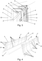
Fig. 3 ein Detail ausFig. 2 ; -
Fig. 4 das Betonleitwandelement ausFig. 2 als Explosionsdarstellung; und -
Fig. 5 ein Stapel aus Bewehrungselementen der zweiten bevorzugten Ausführungsform in einer axonometrischen Darstellung.
-
Fig. 1 a concrete barrier element with a first preferred embodiment of the - Reinforcement elements in an axonometric representation;
-
Fig. 2 a concrete barrier element with a second preferred embodiment according to the invention - the reinforcement elements in an axonometric representation;
-
Fig. 3 a detail fromFig. 2 ; -
Fig. 4 the concrete barrier element made ofFig. 2 as an exploded view; and -
Fig. 5 a stack of reinforcement elements of the second preferred embodiment in an axonometric representation.
Die
Es ist vorgesehen, dass das Bewehrungselement 1 Längsbewehrungsstäbe 4 und quer zu den Längsbewehrungsstäben 4 verlaufende und mit den Längsbewehrungsstäben 4 verbundene, vorzugsweise verschweißte, Bügel 5 aufweist. Die Längsbewehrungsstäbe 4 sind dazu vorgesehen in dem Betonleitwandelement 3 in Längsrichtung zu verlaufen. Die Längsbewehrungsstäbe 4 sind mittels Bügeln 5 miteinander verbunden. Durch die Längsbewehrungsstäbe 4 und die Bügel 5 wird bevorzugt ein zweidimensionales, gekrümmtes Gitter aufgebaut. Die Bügel 5 können insbesondere normal zu den Längsbewehrungsstäbe 4 verlaufen. In den
Bevorzugt besteht das Bewehrungselement 1 aus den Längsbewehrungsstäben 4 und den Bügeln 5.Preferably, the
Weiter ist vorgesehen, dass das Bewehrungselement 1 zumindest einen ersten Bereich 6 aufweist, und dass der erste Bereich 6 im Wesentlichen das Abweiseprofil aufweist. Das Bewehrungselement 1 kann hierbei lediglich aus dem ersten Bereich 6 bestehen, oder weitere Bereiche 7,9 umfassen. Der erste Bereich 6 ist im Wesentlichen geformt wie das Abweiseprofil des herzustellenden Betonleitwandelements 3. Der erste Bereich 6 kann insbesondere im Wesentlichen wie die wenigstens eine Längsseite 2 des Betonleitwandelements 3 ausgebildet sein. Derart kann der erste Bereich 6 des Bewehrungselements 1 im Betonkörper des Betonleitwandelements 3 im Wesentlichen dem Verlauf der wenigstens einen Längsseite 2 des Betonleitwandelements 3 folgend angeordnet sein.It is further provided that the
Dadurch ergibt sich der Vorteil, dass Betonleitwandelemente 3 mit weniger Aufwand aber höherer Zuverlässigkeit hergestellt werden können. Hierbei werden die Längsbewehrungsstäbe 4 und Bügel 5 bereits so geformt, dass diese zumindest bereichsweise das Abweiseprofil des herzustellenden Betonleitwandelements 3 aufweisen, wodurch eine sehr stabile Bewehrung nahe an den relevanten Oberflächen positioniert angeordnet sein kann. Dadurch erübrigt sich ein komplexer Aufbau mit filigranen Baustahlmatten an exponierten Stellen. Als weiterer Vorteil zeigt sich, dass die bisherigen Überlappungen von Längsbewehrungsstäbe, Bügeln und Bewehrungsmatten sich auf das Überlappen der Längsbewehrungsstäbe mit den Bügeln reduziert. Weiters können die Bewehrungselemente 1 bereits in hohen Stückzahlen vorgefertigt werden, und anschließend zu den Betonwerken geliefert werden, wo dann die Betonleitwandelemente 3 gegossen werden. Dadurch kann die Herstellung wesentlich wirtschaftlicher, aber auch mit engeren Fertigungstoleranzen erfolgen.This results in the advantage that
Die Längsbewehrungsstäben 4 können insbesondere gerade sein.The longitudinal reinforcement bars 4 can in particular be straight.
Die Längsbewehrungsstäbe 4 können insbesondere aus Bewehrungsstahl sein.The longitudinal reinforcement bars 4 can in particular be made of reinforcing steel.
Sämtliche Längsbewehrungsstäbe 4 eines Bewehrungselements 1 können insbesondere gleich ausgebildet sein.All longitudinal reinforcement bars 4 of a
Die Bügel 5 können bevorzugt als, insbesondere mit einem vorgebbaren Radius, abgewinkelte Bewehrungsstäbe ausgebildet sein. Die Bügel können im ersten Bereich 6 insbesondere dem Abweiseprofil folgend verlaufend ausgebildet sein.The
Die Bügel 5 können bevorzugt aus starren Bewehrungsstäben ausgebildet sein.The
Die Bügel 5 können insbesondere aus Bewehrungsstahl sein.The
Sämtliche Bügel 5 eines Bewehrungselements 1 können insbesondere gleich ausgebildet sein.All
Die Längsbewehrungsstäbe 4 und die Bügel 5 können bevorzugt miteinander verschweißt sein.The longitudinal reinforcement bars 4 and the
Weiters ist ein Betonleitwandelement 3 für ein Fahrzeugrückhaltesystem vorgesehen, wobei das Betonleitwandelement 3 an wenigstens einer Längsseite 2 das Abweiseprofil aufweist, wobei im Bereich der wenigstens einen Längsseite 2 das Bewehrungselement 1 oberflächennah angeordnet ist. Das Betonleitwandelement 3 weist einen, in den
Das Betonleitwandelement 3 kann insbesondere zwei Längsseiten 2, zwei Stirnseiten 10, eine Oberseite 8 sowie eine Standfläche aufweisen.The
Wenigstens eine der Längsseiten 2 weist das Abweiseprofil auf.At least one of the
Bevorzugt können beide Längsseiten 2 das Abweiseprofil aufweisen, wie dies beispielhaft in den bevorzugten Ausführungsformen in
Eine Länge der Längsbewehrungsstäben 4 kann insbesondere im Wesentlichen einer Länge des Betonleitwandelementes 3 entsprechen.A length of the longitudinal reinforcement bars 4 can in particular essentially correspond to a length of the
Die Bügel können bevorzugt im Wesentlichen von der Standfläche bis zumindest im Wesentlichen zur Oberseite 8 verlaufen.The brackets can preferably extend substantially from the base to at least substantially the
Das Betonleitwandelement 3 kann weiters, in den Fig. nicht dargestellte, zum stirnseitigen Kuppeln mehrerer Betonleitwandelemente 3 stirnseitig angeordnete Kupplungseinrichtungen aufweisen. Die Kupplungseinrichtungen an beiden Stirnseiten 10 können insbesondere mit den Bewehrungselementen 1 und/oder zusätzlichen Zugbändern verbunden sein.The
Weiters ist ein Verfahren zur Herstellung des, an wenigstens einer Längsseite 2 das Abweiseprofil aufweisendes Betonleitwandelement 3 vorgesehen, wobei die Längsbewehrungsstäbe 4 und die quer zu den Längsbewehrungsstäben 4 verlaufende Bügel 5 zusammen zu dem Bewehrungselement 1 verbunden werden, wobei das Bewehrungselement 1 zumindest den einen ersten Bereich 6 aufweist, wobei der erste Bereich 6 im Wesentlichen das Abweiseprofil aufweist, wobei wenigstens eines der Bewehrungselemente 1 derart in eine Gussform eingebracht wird, dass das wenigstens eine Bewehrungselement 1 bei dem fertigen Betonleitwandelement 3 im Bereich der wenigstens einen Längsseite 2 oberflächennah angeordnet ist, wobei die Gussform zum Ausbilden des Betonleitwandelements 3 mit Beton ausgegossen wird.Furthermore, a method is provided for producing the concrete
Das Verbinden der Längsbewehrungsstäben 4 und der Bügel 5 erfolgt bevorzugt durch Verschweißen.The longitudinal reinforcement bars 4 and the
Insbesondere können die Längsbewehrungsstäben 4 und die Bügel 5 miteinander verschweißt, und die Bügel 5 anschließend in die Form des Abweiseprofils gebogen werden.In particular, the longitudinal reinforcement bars 4 and the
Alternativ können die Bügel 5 zunächst gebogen werden, und anschließend mit den Längsbewehrungsstäben 4 verschweißt werden.Alternatively, the
Bevorzugt kann vorgesehen sein, dass die Bewehrungselemente 1 zumindest zum Teil, bevorzugt komplette, maschinell hergestellt werden. Insbesondere kann das Biegen der Bügel 5 und das Verschweißen in einer Anlage erfolgen. Alternativ können die Bewehrungselemente 1 in einer Kombination von Maschinen- und Handschweißung umgesetzt werden.Preferably, it can be provided that the
Es ist vorgesehen, dass das Abweiseprofil ein New Jersey Profil oder ein Step Profil ist. In den bevorzugten Ausführungsformen in
Bevorzugt kann vorgesehen sein, dass die Längsbewehrungsstäbe 4 einen anderen Durchmesser aufweisen als die Bügel 5. Insbesondere kann vorgesehen sein, dass sämtliche Längsbewehrungsstäbe 4 einen ersten Durchmesser aufweisen, dass sämtliche Bügel 5 einen zweiten Durchmesser aufweisen, und dass der erste Durchmesser ungleich ist dem zweiten Durchmesser. Hierbei kann der erste Durchmesser und der zweite Durchmesser derart gewählt sein, dass die Durchmesser an die Rückhalteerfordernisse angepasst sind, und bei den Bügeln 5 die Schwächung an den Biegestellen ausgeglichen werden können.Preferably, it can be provided that the longitudinal reinforcement bars 4 have a different diameter than the
Weiters kann vorgesehen sein, dass ein Abstand der Bügel 5 zueinander variabel ist, und insbesondere in einem Bereich der Enden der Längsbewehrungsstäbe 4 kleiner ist als in einem Mittelbereich der Längsbewehrungsstäbe 4. Dadurch ist mehr Bewehrungsmaterial in der Nähe der Stirnseiten 10 angeordnet, wo die Gefahr von Beschädigungen und Abplatzungen höher ist.Furthermore, it can be provided that a distance between the
Insbesondere kann vorgesehen sein, dass ein Abstand der Längsbewehrungsstäbe 4 zueinander variabel ist, und insbesondere in Randbereichen des Abweiseprofils kleiner ist als in einem Mittelbereich des Abweiseprofils. Dadurch ist mehr Bewehrungsmaterial in der Nähe der an den Rändern des Abweiseprofils angeordneten Oberseite 8 sowie der Standfläche angeordnet, wo die Gefahr von Beschädigungen und Abplatzungen höher ist.In particular, it can be provided that the distance between the longitudinal reinforcement bars 4 is variable and is smaller in particular in edge areas of the deflection profile than in a central area of the deflection profile. This means that more reinforcement material is available in the vicinity of the edges of the deflection profile. arranged
Weiters kann vorgesehen sein, dass ein Abstand der Längsbewehrungsstäbe 4 zueinander in einem Bereich der Enden der Bügel 5 kleiner ist als in einem Mittelbereich der Bügel 5. Dadurch kann eine stärkere Bewehrung an den freien Enden der Bügeln erreicht werden, wo Belastungen größer sein können.Furthermore, it can be provided that a distance between the longitudinal reinforcement bars 4 in an area of the ends of the
Weiters kann vorgesehen sein, dass ein Abstand der Längsbewehrungsstäbe 4 zueinander variabel ist, und insbesondere an den Rändern des ersten Bereiches 6 kleiner ist als in der Mitte des ersten Bereiches 6. Dadurch ist mehr Bewehrungsmaterial in der Nähe der Standfläche und der Oberseite 8, wo die Gefahr von Beschädigungen und Abplatzungen höher ist.Furthermore, it can be provided that a distance between the longitudinal reinforcement bars 4 is variable, and in particular is smaller at the edges of the
Es ist vorgesehen, dass das Bewehrungselement 1 flach ist. Hierbei ist das Bewehrungselement 1 im Wesentlichen wie eine gekrümmte Fläche geformt. Dadurch ergibt sich der Vorteil, dass die Bewehrungselemente 1 einfach gestapelt und dadurch platzsparend transportiert werden können. Ein Stapel aus Bewehrungselementen 1 der zweiten bevorzugten Ausführungsform ist in
Es kann vorgesehen sein, dass die aus wenigstens einem Bewehrungselement 1 gebildete Bewehrung des Betonleitwandelements 3 an der Stirnseite 10 offen ist. Es kann vorgesehen sein, dass das Bewehrungselement 1 lediglich aus dem ersten Bereich 6 besteht.It can be provided that the reinforcement of the concrete
Weiters kann vorgesehen sein, dass an dem ersten Bereich 6 ein zweiter Bereich 7 anschließt, dass der zweite Bereich 7 gegenüber dem ersten Bereich 6 abgewinkelt ist und vorgesehen ist, an einer Oberseite 8 des Betonleitwandelements 3 angeordnet zu sein. Der zweite Bereich 7 kann sich zumindest über eine halbe Breite der Oberseite 8 erstrecken. Dadurch kann ebenfalls die Oberseite 8 bewehrt werden.Furthermore, it can be provided that a
In einer nicht erfindungsgemäßen Ausführungsform kann vorgesehen sein, dass an einem, dem ersten Bereich 6 abgewandten Seite des zweiten Bereiches 7 ein dritter Bereich 9 an dem zweiten Bereich 7 anschließt, und dass der dritte Bereich 9 im Wesentlichen das Abweiseprofil aufweist. Der erste Bereich 6, der zweite Bereich 7 und der dritte Bereich 9 bilden hierbei im Wesentlichen das Profil der beiden Längsseiten 2 zusammen mit der Oberseite 8 des herzustellenden Betonleitwandelements 3 aus. Bei dem Betonleitwandelement 3 kann vorgesehen sein, dass das Betonleitwandelement 3 zwei ein Abweiseprofil aufweisende Längsseiten 2 aufweist, und dass ein einziges Bewehrungselement 1 bei beiden Längsseiten 2 angeordnet ist. Insbesondere kann vorgesehen sein, dass das Betonleitwandelement 3 lediglich ein einziges Bewehrungselement 1 aufweist. Dadurch kann durch im Wesentlichen ein einziges vorgefertigtes Bewehrungselement 1 eine Bewehrung sämtlicher exponierter Flächen eines Betonleitwandelements 3 erreicht werden. Ein derartiges Betonleitwandelement 3 ist beispielhaft in
Alternativ kann vorgesehen sein, dass bei einem Bewehrungselement 1 aus mehreren Bereichen 6,7 lediglich der erste Bereich 6 das Abweiseprofil aufweist.Alternatively, it can be provided that in a
Bevorzugt kann vorgesehen sein, dass das Bewehrungselement 1 lediglich den ersten Bereich 6 und den zweiten Bereich 7 aufweist.Preferably, it can be provided that the
Insbesondere kann vorgesehen sein, dass das Betonleitwandelement 3 zwei ein Abweiseprofil aufweisende Längsseiten 2 aufweist, und dass bei beiden Längsseiten 2 jeweils ein Bewehrungselement 1 angeordnet ist.In particular, it can be provided that the
Das Betonleitwandelement 3 kann hierbei bevorzugt zwei, insbesondere im Wesentlichen gleich ausgebildete, Bewehrungselemente 1 aufweisen, wobei besonders bevorzugt jeweils eines der Bewehrungselemente 1 an einer der Längsseiten 2 angeordnet ist. Durch diesen mehrteiligen Aufbau der Bewehrung kann die Handhabung der Bewehrungselemente 1 vereinfacht werden. Weiters wird die Stapelbarkeit verbessert. Zusätzlich können derartige Bewehrungselemente 1 auch bei Betonleitwandelement 3 eingesetzt werden, die lediglich eine Längsseite 2 mit dem Abweiseprofil aufweisen. Derart ausgebildete Bewehrungselement 1 sind beispielhaft in
Bevorzugt kann vorgesehen sein, dass sich die beiden Bewehrungselemente 1 im Bereich einer Oberseite 8 des Betonleitwandelements 3 aneinander grenzen, insbesondere überlappen. Dadurch können beide Bewehrungselemente 1 im Bereich der Oberseite 8 einfach miteinander verbunden werden. Hierbei können die Bügel 5 der beiden Bewehrungselemente 1 derart leicht zueinander versetzt werden, dass diese im zweiten Bereich 7 nebeneinander angeordnet sind.Preferably, it can be provided that the two
Claims (12)
- Reinforcing element (1) for a concrete barrier-wall element (3), which concrete barrier-wall element has a repelling profile on at least one longitudinal side (2), wherein the repelling profile is a New Jersey profile or a step profile, wherein the reinforcing element (1) has longitudinal reinforcing bars (4) and has bows (5), which extend transversely to the longitudinal reinforcing bars (4) and are welded to the longitudinal reinforcing bars (4), that the reinforcing element (1) has at least a first region (6), that the first region (6) is substantially formed like the repelling profile of the concrete barrier-wall element (3) to be produced, characterized in that the longitudinal reinforcing bars (4) and the bows (5) make up a two-dimensional curved grid, and that the reinforcing element (1) in order to be stacked easily and thus transported in a space-saving manner is flat and formed substantially like a curved surface.
- Reinforcing element (1) according to claim 1, characterized in that a distance between the bows (5) is variable with respect to one another, and in particular is smaller in a region of the ends of the longitudinal reinforcing bars (4) than in a central region of the longitudinal reinforcing bars (4).
- Reinforcing element (1) according to claim 1 or 2, characterized in that a distance between the longitudinal reinforcing bars (4) is variable with respect to one another, and in particular is smaller in edge regions of the repelling profile than in a central region of the repelling profile.
- Reinforcing element (1) according to one of claims 1 to 3, characterized in that a distance between the longitudinal reinforcing bars (4) is smaller with respect to one another in a region of the ends of the bows (5) than in a central region of the bows (5).
- Reinforcing element (1) according to one of claims 1 to 4, characterized in that the longitudinal reinforcing bars (4) have a different diameter than the bows (5).
- Reinforcing element (1) according to one of claims 1 to 5, characterized in that a second region (7) adjoins the first region (6), that the second region (7) is angled relative to the first region (6) and is provided to be arranged on an upper side (8) of the concrete barrier-wall element (3).
- Reinforcing element (1) according to claim 6, characterized in that the reinforcing element (1) has only the first region (6) and the second region (7).
- Concrete barrier-wall element (3) for a vehicle retention system, which concrete barrier-wall element (3) has a repelling profile on at least one longitudinal side (2), wherein a reinforcing element (1) according to one of claims 1 to 7 is arranged close to the surface in the region of the at least one longitudinal side (2).
- Concrete barrier-wall element (3) according to claim 8, characterized in that the concrete barrier-wall element (3) has two longitudinal sides (2) having a repelling profile, and that one reinforcing element (1) each is arranged on both longitudinal sides (2).
- Concrete barrier-wall element (3) according to claim 8 or 9, characterized in that the two reinforcing elements (1) at least adjoin one another, in particular overlap in the region of an upper side (8) of the concrete barrier-wall element (3).
- Method for producing a concrete barrier-wall element (3) having a repelling profile on at least one longitudinal side (2), wherein the repelling profile is a New Jersey profile or a step profile, wherein longitudinal reinforcing bars (4) and bows (5), which extend transversely to the longitudinal reinforcing bars (4), are connected together to form a reinforcing element (1), which reinforcing element (1) has at least one first region (6), wherein the first region (6) is substantially formed like the repelling profile of the concrete barrier-wall element (3) to be produced, wherein a two-dimensional curved grid is constructed by means of the longitudinal reinforcing bars (4) and the bows (5), wherein the reinforcing element (1) is formed substantially like a curved surface, wherein at least one of the reinforcing elements (1) is introduced into a casting mould in such a way that the at least one reinforcing element (1) is arranged close to the surface in the region of the at least one longitudinal side (2) in the finished concrete barrier-wall element (3), wherein the casting mould is cast with concrete to form the concrete barrier-wall element (3).
- Method according to claim 11, characterized in that the reinforcing elements (1) are machine-made.
Priority Applications (2)
| Application Number | Priority Date | Filing Date | Title |
|---|---|---|---|
| HRP20250053TT HRP20250053T1 (en) | 2016-12-07 | 2017-11-27 | REINFORCEMENT ELEMENT |
| RS20250012A RS66378B1 (en) | 2016-12-07 | 2017-11-27 | REINFORCEMENT ELEMENT |
Applications Claiming Priority (2)
| Application Number | Priority Date | Filing Date | Title |
|---|---|---|---|
| ATA51118/2016A AT518889B1 (en) | 2016-12-07 | 2016-12-07 | REINFORCING ELEMENT |
| PCT/EP2017/080537 WO2018104094A1 (en) | 2016-12-07 | 2017-11-27 | Reinforcing element |
Publications (3)
| Publication Number | Publication Date |
|---|---|
| EP3551803A1 EP3551803A1 (en) | 2019-10-16 |
| EP3551803B1 true EP3551803B1 (en) | 2024-12-18 |
| EP3551803C0 EP3551803C0 (en) | 2024-12-18 |
Family
ID=60702630
Family Applications (1)
| Application Number | Title | Priority Date | Filing Date |
|---|---|---|---|
| EP17816523.9A Active EP3551803B1 (en) | 2016-12-07 | 2017-11-27 | Reinforcing element |
Country Status (25)
| Country | Link |
|---|---|
| US (1) | US11028546B2 (en) |
| EP (1) | EP3551803B1 (en) |
| JP (1) | JP2020501045A (en) |
| KR (1) | KR20190092465A (en) |
| CN (1) | CN110168168A (en) |
| AT (1) | AT518889B1 (en) |
| AU (1) | AU2017373483B2 (en) |
| BR (1) | BR112019010609B1 (en) |
| CA (1) | CA3046043A1 (en) |
| CL (1) | CL2019001460A1 (en) |
| ES (1) | ES3002232T3 (en) |
| HR (1) | HRP20250053T1 (en) |
| HU (1) | HUE069867T2 (en) |
| IL (1) | IL267053B (en) |
| MA (1) | MA48593A (en) |
| MX (1) | MX2019006355A (en) |
| NZ (1) | NZ754017A (en) |
| PE (1) | PE20191122A1 (en) |
| PL (1) | PL3551803T3 (en) |
| RS (1) | RS66378B1 (en) |
| RU (1) | RU2756443C2 (en) |
| TN (1) | TN2019000169A1 (en) |
| UA (1) | UA128520C2 (en) |
| WO (1) | WO2018104094A1 (en) |
| ZA (1) | ZA201904435B (en) |
Families Citing this family (2)
| Publication number | Priority date | Publication date | Assignee | Title |
|---|---|---|---|---|
| CN113021602A (en) * | 2021-02-09 | 2021-06-25 | 浙江交工集团股份有限公司 | Construction method for prefabricated bridge steel sleeve stand column |
| US20240110348A1 (en) * | 2022-09-30 | 2024-04-04 | Investissements Qmb Inc. | Barrier for roadway |
Citations (1)
| Publication number | Priority date | Publication date | Assignee | Title |
|---|---|---|---|---|
| US6394410B1 (en) * | 2000-07-06 | 2002-05-28 | Randy L. Thompson | Adjustable reinforcement insertion guide for a slip form concrete barrier mold |
Family Cites Families (26)
| Publication number | Priority date | Publication date | Assignee | Title |
|---|---|---|---|---|
| US3308724A (en) * | 1963-10-08 | 1967-03-14 | Smith Henry Such | Roadway guard rail barrier |
| US3678815A (en) * | 1970-08-27 | 1972-07-25 | George C Younker | Concrete structural member |
| US4084928A (en) * | 1976-11-03 | 1978-04-18 | Cmi Corporation | Slip form having reinforcement accommodating means |
| US4423854A (en) * | 1979-11-26 | 1984-01-03 | International Barrier Corporation | Roadway barrier |
| US4494892A (en) * | 1982-12-29 | 1985-01-22 | Henri Vidal | Traffic barrier, barrier element and method of construction |
| US4605336A (en) * | 1984-07-12 | 1986-08-12 | Slaw Sr Robert A | Joint construction of concrete members |
| US4668462A (en) * | 1986-01-17 | 1987-05-26 | Fomico International, Inc. | Adjustable mold for concrete median barrier |
| US4806044A (en) * | 1988-05-20 | 1989-02-21 | Barrier Systems, Inc. | Anti-crash lane barrier with self-centering hinges |
| JP3165514B2 (en) * | 1992-08-13 | 2001-05-14 | 太平洋セメント株式会社 | Concrete guard fence |
| JP2588117B2 (en) * | 1992-08-19 | 1997-03-05 | 住倉鋼材株式会社 | How to build a concrete structure |
| US5651635A (en) * | 1995-04-24 | 1997-07-29 | Schuylkill Products, Inc. | Concrete barrier with reinforcement |
| JP2763279B2 (en) * | 1995-09-14 | 1998-06-11 | 旭コンクリート工業株式会社 | Construction method of concrete guard fence |
| US5685665A (en) * | 1996-05-09 | 1997-11-11 | Lembo; M. Carl | Roadway barrier and method of installation |
| JP2948149B2 (en) * | 1996-06-19 | 1999-09-13 | ミサワセラミックス株式会社 | Structure and construction method of concrete protection fence |
| NL1012439C2 (en) * | 1999-06-25 | 2001-01-10 | Haitsma Beton Bv | Separation element. |
| FR2801913A1 (en) * | 1999-12-07 | 2001-06-08 | Bernard Abram | DEVICE FOR CONTINUOUS CONSTRUCTION OF ROAD SAFETY BARRIER ELEMENTS |
| US6526721B1 (en) * | 2000-05-26 | 2003-03-04 | Brian D. Nash | Fluid-impervious barrier/keyway form support apparatus, system and related method |
| US6679649B1 (en) * | 2002-12-27 | 2004-01-20 | Sps New England, Inc. | Barrier wall apparatus and method of construction |
| FR2862674B1 (en) * | 2003-11-20 | 2007-05-25 | Bonna Sabla | REALIZATION OF A SAFETY BARRIER FOR ROAD TRAFFIC PATHWAY |
| JP2008095363A (en) * | 2006-10-11 | 2008-04-24 | Fair Design:Kk | Guard fence |
| AT507611B1 (en) * | 2008-11-20 | 2010-08-15 | Mathias Mag Redlberger | CONNECTING DEVICE FOR CONNECTING TRACE ELEMENTS TO TRAFFIC SURFACES |
| AT11483U1 (en) * | 2009-06-15 | 2010-11-15 | Kirchdorfer Fertigteilholding | tension element |
| GB2492773B (en) * | 2011-07-11 | 2016-08-17 | Francis Maydew Nigel | Barricade component |
| WO2014036237A1 (en) * | 2012-09-01 | 2014-03-06 | Easi-Set Industries, Inc. | Interlocking highway barrier structure |
| US9869066B2 (en) | 2013-11-27 | 2018-01-16 | Howard Cooper | System and method for slip forming concrete barriers |
| US9598827B1 (en) * | 2016-08-20 | 2017-03-21 | Victor Nicholas Pavloff, Jr. | Barrier rail retrofit device assembly |
-
2016
- 2016-12-07 AT ATA51118/2016A patent/AT518889B1/en active
-
2017
- 2017-11-27 EP EP17816523.9A patent/EP3551803B1/en active Active
- 2017-11-27 BR BR112019010609-0A patent/BR112019010609B1/en active IP Right Grant
- 2017-11-27 NZ NZ754017A patent/NZ754017A/en unknown
- 2017-11-27 JP JP2019531291A patent/JP2020501045A/en active Pending
- 2017-11-27 PL PL17816523.9T patent/PL3551803T3/en unknown
- 2017-11-27 MX MX2019006355A patent/MX2019006355A/en unknown
- 2017-11-27 PE PE2019001086A patent/PE20191122A1/en unknown
- 2017-11-27 CN CN201780074457.9A patent/CN110168168A/en active Pending
- 2017-11-27 CA CA3046043A patent/CA3046043A1/en active Pending
- 2017-11-27 UA UAA201906236A patent/UA128520C2/en unknown
- 2017-11-27 HU HUE17816523A patent/HUE069867T2/en unknown
- 2017-11-27 RS RS20250012A patent/RS66378B1/en unknown
- 2017-11-27 AU AU2017373483A patent/AU2017373483B2/en active Active
- 2017-11-27 KR KR1020197018680A patent/KR20190092465A/en not_active Ceased
- 2017-11-27 WO PCT/EP2017/080537 patent/WO2018104094A1/en not_active Ceased
- 2017-11-27 ES ES17816523T patent/ES3002232T3/en active Active
- 2017-11-27 TN TNP/2019/000169A patent/TN2019000169A1/en unknown
- 2017-11-27 HR HRP20250053TT patent/HRP20250053T1/en unknown
- 2017-11-27 MA MA048593A patent/MA48593A/en unknown
- 2017-11-27 US US16/467,663 patent/US11028546B2/en active Active
- 2017-11-27 RU RU2019120989A patent/RU2756443C2/en active
-
2019
- 2019-05-29 CL CL2019001460A patent/CL2019001460A1/en unknown
- 2019-06-03 IL IL267053A patent/IL267053B/en active IP Right Grant
- 2019-07-05 ZA ZA2019/04435A patent/ZA201904435B/en unknown
Patent Citations (1)
| Publication number | Priority date | Publication date | Assignee | Title |
|---|---|---|---|---|
| US6394410B1 (en) * | 2000-07-06 | 2002-05-28 | Randy L. Thompson | Adjustable reinforcement insertion guide for a slip form concrete barrier mold |
Also Published As
| Publication number | Publication date |
|---|---|
| BR112019010609B1 (en) | 2023-01-24 |
| CA3046043A1 (en) | 2018-06-14 |
| EP3551803C0 (en) | 2024-12-18 |
| US11028546B2 (en) | 2021-06-08 |
| AT518889A4 (en) | 2018-02-15 |
| AU2017373483B2 (en) | 2023-04-06 |
| RU2019120989A3 (en) | 2021-03-26 |
| IL267053B (en) | 2019-09-26 |
| AT518889B1 (en) | 2018-02-15 |
| CN110168168A (en) | 2019-08-23 |
| TN2019000169A1 (en) | 2020-10-05 |
| ES3002232T3 (en) | 2025-03-06 |
| PE20191122A1 (en) | 2019-08-28 |
| WO2018104094A1 (en) | 2018-06-14 |
| RS66378B1 (en) | 2025-02-28 |
| JP2020501045A (en) | 2020-01-16 |
| MA48593A (en) | 2020-03-18 |
| CL2019001460A1 (en) | 2019-09-13 |
| PL3551803T3 (en) | 2025-03-31 |
| HRP20250053T1 (en) | 2025-03-14 |
| HUE069867T2 (en) | 2025-04-28 |
| IL267053A (en) | 2019-07-31 |
| AU2017373483A1 (en) | 2019-07-04 |
| NZ754017A (en) | 2025-05-02 |
| US20200087875A1 (en) | 2020-03-19 |
| BR112019010609A2 (en) | 2019-09-17 |
| UA128520C2 (en) | 2024-08-07 |
| EP3551803A1 (en) | 2019-10-16 |
| RU2756443C2 (en) | 2021-09-30 |
| KR20190092465A (en) | 2019-08-07 |
| ZA201904435B (en) | 2021-05-26 |
| MX2019006355A (en) | 2019-10-21 |
| RU2019120989A (en) | 2021-01-11 |
Similar Documents
| Publication | Publication Date | Title |
|---|---|---|
| EP1927699B1 (en) | Traffic guide wall | |
| EP2322719A2 (en) | Devices for bridging of expansion joints, profile construction and method for producing joint profiles | |
| EP2075388B1 (en) | Reinforcement elements and steel or reinforced concrete sections produced with same | |
| EP3697980B1 (en) | Horizontal bar | |
| EP3551803B1 (en) | Reinforcing element | |
| EP2623435A1 (en) | Stackable pallet container and wire mesh outer shell therefor | |
| EP2209952B1 (en) | Spacer and structural component for producing a wall construction, and method and device | |
| EP2025816B1 (en) | Method for manufacturing a wall element and wall element manufactured according to the method for a traffic guide wall | |
| EP3201397B1 (en) | Traffic guide wall | |
| EP2826650B1 (en) | Frame for a vehicle sliding roof with cable channels | |
| EP2446088B1 (en) | End element | |
| DE10116673A1 (en) | Transport anchor for a prefabricated concrete double wall comprises a transverse part connected to the arms of a U-shaped base part and having free arms extending in a plane intersecting the plane in which the arms of the base part extend | |
| AT512411B1 (en) | Ortbetonschutzwand | |
| DE29821624U1 (en) | Connecting element for sheet piles | |
| EP4621129A1 (en) | Box profile for the vehicle restraint system and method for producing said box profile | |
| EP1878846B1 (en) | Connecting cage, its use and connecting reinforcement manufactured therewith | |
| DE4207434C2 (en) | Fastener | |
| DE20023821U1 (en) | Shaft cover used in road construction comprises a frame-like covering element partly filled with concrete | |
| DE29512788U1 (en) | Shear reinforcement for concrete components | |
| DE4225640A1 (en) | Reinforcing connector between reinforced-concrete components | |
| EP3608476A1 (en) | Wall element for a traffic guiding and / or blocking wall | |
| EP0565940A1 (en) | Lamellated thin sheet tubular sleeve inserted in engine cylinder block casting | |
| DE102017119768A1 (en) | Formwork for the production of industrial floors | |
| DE102012106249A1 (en) | Bumper profile for bumper of motor car, has weakening locations that are formed in inner profile portion inside outer profile portion | |
| DE2166871A1 (en) | High-ribbed round concrete reinforcing rod - has flattened sections and sections deviating from circle shape |
Legal Events
| Date | Code | Title | Description |
|---|---|---|---|
| REG | Reference to a national code |
Ref country code: HR Ref legal event code: TUEP Ref document number: P20250053T Country of ref document: HR |
|
| STAA | Information on the status of an ep patent application or granted ep patent |
Free format text: STATUS: UNKNOWN |
|
| STAA | Information on the status of an ep patent application or granted ep patent |
Free format text: STATUS: THE INTERNATIONAL PUBLICATION HAS BEEN MADE |
|
| PUAI | Public reference made under article 153(3) epc to a published international application that has entered the european phase |
Free format text: ORIGINAL CODE: 0009012 |
|
| STAA | Information on the status of an ep patent application or granted ep patent |
Free format text: STATUS: REQUEST FOR EXAMINATION WAS MADE |
|
| 17P | Request for examination filed |
Effective date: 20190708 |
|
| AK | Designated contracting states |
Kind code of ref document: A1 Designated state(s): AL AT BE BG CH CY CZ DE DK EE ES FI FR GB GR HR HU IE IS IT LI LT LU LV MC MK MT NL NO PL PT RO RS SE SI SK SM TR |
|
| AX | Request for extension of the european patent |
Extension state: BA ME |
|
| DAX | Request for extension of the european patent (deleted) | ||
| RAP1 | Party data changed (applicant data changed or rights of an application transferred) |
Owner name: DELTA BLOC INTERNATIONAL GMBH |
|
| STAA | Information on the status of an ep patent application or granted ep patent |
Free format text: STATUS: EXAMINATION IS IN PROGRESS |
|
| 17Q | First examination report despatched |
Effective date: 20200617 |
|
| RAP3 | Party data changed (applicant data changed or rights of an application transferred) |
Owner name: DELTABLOC INTERNATIONAL GMBH |
|
| GRAP | Despatch of communication of intention to grant a patent |
Free format text: ORIGINAL CODE: EPIDOSNIGR1 |
|
| STAA | Information on the status of an ep patent application or granted ep patent |
Free format text: STATUS: GRANT OF PATENT IS INTENDED |
|
| INTG | Intention to grant announced |
Effective date: 20240904 |
|
| GRAS | Grant fee paid |
Free format text: ORIGINAL CODE: EPIDOSNIGR3 |
|
| GRAA | (expected) grant |
Free format text: ORIGINAL CODE: 0009210 |
|
| STAA | Information on the status of an ep patent application or granted ep patent |
Free format text: STATUS: THE PATENT HAS BEEN GRANTED |
|
| AK | Designated contracting states |
Kind code of ref document: B1 Designated state(s): AL AT BE BG CH CY CZ DE DK EE ES FI FR GB GR HR HU IE IS IT LI LT LU LV MC MK MT NL NO PL PT RO RS SE SI SK SM TR |
|
| REG | Reference to a national code |
Ref country code: GB Ref legal event code: FG4D Free format text: NOT ENGLISH |
|
| REG | Reference to a national code |
Ref country code: CH Ref legal event code: EP |
|
| REG | Reference to a national code |
Ref country code: DE Ref legal event code: R096 Ref document number: 502017016619 Country of ref document: DE |
|
| REG | Reference to a national code |
Ref country code: IE Ref legal event code: FG4D Free format text: LANGUAGE OF EP DOCUMENT: GERMAN |
|
| U01 | Request for unitary effect filed |
Effective date: 20250103 |
|
| U07 | Unitary effect registered |
Designated state(s): AT BE BG DE DK EE FI FR IT LT LU LV MT NL PT RO SE SI Effective date: 20250115 |
|
| REG | Reference to a national code |
Ref country code: ES Ref legal event code: FG2A Ref document number: 3002232 Country of ref document: ES Kind code of ref document: T3 Effective date: 20250306 Ref country code: GR Ref legal event code: EP Ref document number: 20250400144 Country of ref document: GR Effective date: 20250211 |
|
| REG | Reference to a national code |
Ref country code: SK Ref legal event code: T3 Ref document number: E 45786 Country of ref document: SK |
|
| REG | Reference to a national code |
Ref country code: HR Ref legal event code: T1PR Ref document number: P20250053 Country of ref document: HR |
|
| REG | Reference to a national code |
Ref country code: HU Ref legal event code: AG4A Ref document number: E069867 Country of ref document: HU |
|
| PG25 | Lapsed in a contracting state [announced via postgrant information from national office to epo] |
Ref country code: SM Free format text: LAPSE BECAUSE OF FAILURE TO SUBMIT A TRANSLATION OF THE DESCRIPTION OR TO PAY THE FEE WITHIN THE PRESCRIBED TIME-LIMIT Effective date: 20241218 |
|
| PG25 | Lapsed in a contracting state [announced via postgrant information from national office to epo] |
Ref country code: IS Free format text: LAPSE BECAUSE OF FAILURE TO SUBMIT A TRANSLATION OF THE DESCRIPTION OR TO PAY THE FEE WITHIN THE PRESCRIBED TIME-LIMIT Effective date: 20250418 |
|
| VS25 | Lapsed in a validation state [announced via postgrant information from nat. office to epo] |
Ref country code: MD Free format text: LAPSE BECAUSE OF FAILURE TO SUBMIT A TRANSLATION OF THE DESCRIPTION OR TO PAY THE FEE WITHIN THE PRESCRIBED TIME-LIMIT Effective date: 20241218 |
|
| U20 | Renewal fee for the european patent with unitary effect paid |
Year of fee payment: 9 Effective date: 20250902 |
|
| PGFP | Annual fee paid to national office [announced via postgrant information from national office to epo] |
Ref country code: PL Payment date: 20250909 Year of fee payment: 9 |
|
| PLBE | No opposition filed within time limit |
Free format text: ORIGINAL CODE: 0009261 |
|
| STAA | Information on the status of an ep patent application or granted ep patent |
Free format text: STATUS: NO OPPOSITION FILED WITHIN TIME LIMIT |
|
| 26N | No opposition filed |
Effective date: 20250919 |
|
| PGFP | Annual fee paid to national office [announced via postgrant information from national office to epo] |
Ref country code: HU Payment date: 20251127 Year of fee payment: 9 |
|
| REG | Reference to a national code |
Ref country code: HR Ref legal event code: ODRP Ref document number: P20250053 Country of ref document: HR Payment date: 20251120 Year of fee payment: 9 |
|
| PGFP | Annual fee paid to national office [announced via postgrant information from national office to epo] |
Ref country code: GB Payment date: 20251120 Year of fee payment: 9 |
|
| PGFP | Annual fee paid to national office [announced via postgrant information from national office to epo] |
Ref country code: NO Payment date: 20251118 Year of fee payment: 9 |
|
| PGFP | Annual fee paid to national office [announced via postgrant information from national office to epo] |
Ref country code: HR Payment date: 20251120 Year of fee payment: 9 |
|
| PGFP | Annual fee paid to national office [announced via postgrant information from national office to epo] |
Ref country code: TR Payment date: 20251121 Year of fee payment: 9 Ref country code: GR Payment date: 20251117 Year of fee payment: 9 |
|
| PGFP | Annual fee paid to national office [announced via postgrant information from national office to epo] |
Ref country code: CZ Payment date: 20251118 Year of fee payment: 9 |
|
| PGFP | Annual fee paid to national office [announced via postgrant information from national office to epo] |
Ref country code: SK Payment date: 20251121 Year of fee payment: 9 |
|
| PGFP | Annual fee paid to national office [announced via postgrant information from national office to epo] |
Ref country code: RS Payment date: 20251114 Year of fee payment: 9 |
|
| PGFP | Annual fee paid to national office [announced via postgrant information from national office to epo] |
Ref country code: ES Payment date: 20251216 Year of fee payment: 9 |